Embed Size (px)
Citation preview
AI2006 Network Yard AEI Reader System
March 5, 2012
Copyright 2006 Softrail All rights reserved

AI2006 Network Yard AEI Reader System
ii March 5, 2012
Softrail 1098 Venetia Road
Eighty Four, PA 15330
Tel. 888 872-4612 (toll free US and Canada only) Tel. 724 942-1473 Fax. 724 942-1480
E-mail [email protected] Web Page www.aeitag.com
AI2006 Network Yard AEI Reader System
iii March 5, 2012
Table of Contents 1. BRIEF OVERVIEW.................................................................................................... 1 2. EQUIPMENT INSTALLATION ...................................................................................... 3 2.1. Deliverables .............................................................................................................3 2.2. SmartPass Reader Installation ....................................................................................3 2.3. Controller Installation.................................................................................................4 2.4. Doppler Radar Installation (Optional)...........................................................................16 2.5. QT50R Presence Radar (Optional) .............................................................................16 3. INSTALLATION PICTURES....................................................................................... 18 4. CONFIGURATION PARAMETERS............................................................................... 21 4.1. Contact Information Setup........................................................................................23 4.2. Reader Site Parameters ..........................................................................................24 4.2.1. Reader Message Setup............................................................................................25 4.2.2. Site Parameters .....................................................................................................26 4.2.3. Tag Filter Setup ......................................................................................................27 4.2.4. SmartPass Reader Parameters ................................................................................30 4.3. Email Setup............................................................................................................31 4.4. FTP Setup..............................................................................................................32 4.5. TCP/IP Setup.........................................................................................................33 4.6. Radar Setup ..........................................................................................................34 4.7. Emails Addresses ...................................................................................................36 4.7.1. AEI Data Email Addresses ........................................................................................36 4.7.2. Maintenance Email Addresses ..................................................................................37 4.7.3. Tag Maintenance Email Addresses ............................................................................37 4.7.4. Watchdog Email Addresses......................................................................................37 4.8. Internet Connection Test Setup .................................................................................38 4.9. OEM Folder Setup ...................................................................................................40 5. STATUS DISPLAYS................................................................................................ 41 5.1. System Status........................................................................................................41 5.2. Communication Monitor Display ................................................................................43 5.3. Rail Vehicle Movement Display ..................................................................................44 5.4. Radar Status Display (Optional)..................................................................................45 6. MESSAGES (EMAIL and FTP)................................................................................... 45 6.1. AEI Data Messages.................................................................................................46 6.2. Maintenance Messages ...........................................................................................46 6.3. Message Status .....................................................................................................48 7. TIME UPDATE ...................................................................................................... 48 8. MAINTENANCE AND COMMUNICATION LOGS............................................................ 49 8.1. Maintenance Log File...............................................................................................49 8.2. Communications Log ...............................................................................................50 9. OPTIONS ............................................................................................................. 50 10. ABOUT................................................................................................................ 52 11. FILE MAINTENANCE .............................................................................................. 52 12. TEXT FILE FORMAT ............................................................................................... 53 13. OEM FUNCTIONS .................................................................................................. 59 13.1. Accessing Tag Data ................................................................................................59 13.2. Sending OEM Data ..................................................................................................61 13.2.1. Email Transmit Request File......................................................................................61 13.2.2. FTP Transmit Request File........................................................................................64 13.2.3. OEM Transmit Request Status ..................................................................................66 14. TECHNICAL SUPPORT AND UPDATES ...................................................................... 67
AI2006 Network Yard AEI Reader System
iv March 5, 2012
List of Figures Figure 1 - AEI Reader System Block Diagram.........................................................................................................................2 Figure 2 - 120/240 VAC Controller Layout..............................................................................................................................5 Figure 3 - Terminal Block.........................................................................................................................................................6 Figure 4 - Terminal Assignments..............................................................................................................................................8 Figure 5 - Controller's Ground Stud..........................................................................................................................................9 Figure 6 - Communication Multiplexer ..................................................................................................................................10 Figure 7 - Controller's PDA ....................................................................................................................................................11 Figure 8 - System Status .........................................................................................................................................................12 Figure 9 - Communications Monitor.......................................................................................................................................13 Figure 10 - Rail Car Movements.............................................................................................................................................14 Figure 11 - Main Windows Display........................................................................................................................................15 Figure 12 - Radar Unit with Cable ..........................................................................................................................................16 Figure 13 - QT50R Presence Radar ........................................................................................................................................17 Figure 14 - Installation Picture 1.............................................................................................................................................18 Figure 15 - Installation Picture 2.............................................................................................................................................19 Figure 16 - Installation Picture 3.............................................................................................................................................19 Figure 17 - Installation Picture 4.............................................................................................................................................20 Figure 18 - Setup Menu Items.................................................................................................................................................22 Figure 19- Contact Information Setup ....................................................................................................................................23 Figure 20 - Reader Site Setup .................................................................................................................................................24 Figure 21 - Reader Message Setup..........................................................................................................................................25 Figure 22 - Site Parameters Setup...........................................................................................................................................26 Figure 23 - Tag Filter Setup ....................................................................................................................................................28 Figure 24 - SmartPass Setup ...................................................................................................................................................30 Figure 25 - Email Setup Dialog ..............................................................................................................................................31 Figure 26 - FTP Server Setup Dialog......................................................................................................................................32 Figure 27 - TCP/IP Setup Dialog ............................................................................................................................................34 Figure 28 - Radar Setup Dialog ..............................................................................................................................................35 Figure 29 - AEI Email Address Setup.....................................................................................................................................36 Figure 30 - Watchdog Email Address Setup...........................................................................................................................38 Figure 31 - Internet Connection Test ......................................................................................................................................39 Figure 32 - OEM Folder Setup................................................................................................................................................40 Figure 33 - System Status Display Highlighting Problems.....................................................................................................41 Figure 34 - System Status Display ..........................................................................................................................................42 Figure 35 - Communications Monitor Display .......................................................................................................................43 Figure 36 - Rail Vehicle Movement Displays.........................................................................................................................44 Figure 37 - Radar Status Display ............................................................................................................................................45 Figure 38 - Message Status .....................................................................................................................................................48 Figure 39 - Maintenance Log Display.....................................................................................................................................49 Figure 40 - Communications Log Display..............................................................................................................................50 Figure 41 - Installed Options Display .....................................................................................................................................51 Figure 42 - About Display ......................................................................................................................................................52
AI2006 Network Yard AEI Reader System
1 March 5, 2012
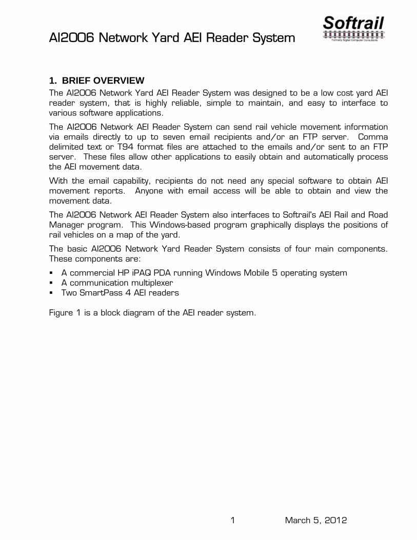
1. BRIEF OVERVIEW The AI2006 Network Yard AEI Reader System was designed to be a low cost yard AEI reader system, that is highly reliable, simple to maintain, and easy to interface to various software applications.
The AI2006 Network AEI Reader System can send rail vehicle movement information via emails directly to up to seven email recipients and/or an FTP server. Comma delimited text or T94 format files are attached to the emails and/or sent to an FTP server. These files allow other applications to easily obtain and automatically process the AEI movement data.
With the email capability, recipients do not need any special software to obtain AEI movement reports. Anyone with email access will be able to obtain and view the movement data.
The AI2006 Network AEI Reader System also interfaces to Softrail's AEI Rail and Road Manager program. This Windows-based program graphically displays the positions of rail vehicles on a map of the yard.
The basic AI2006 Network Yard Reader System consists of four main components. These components are:
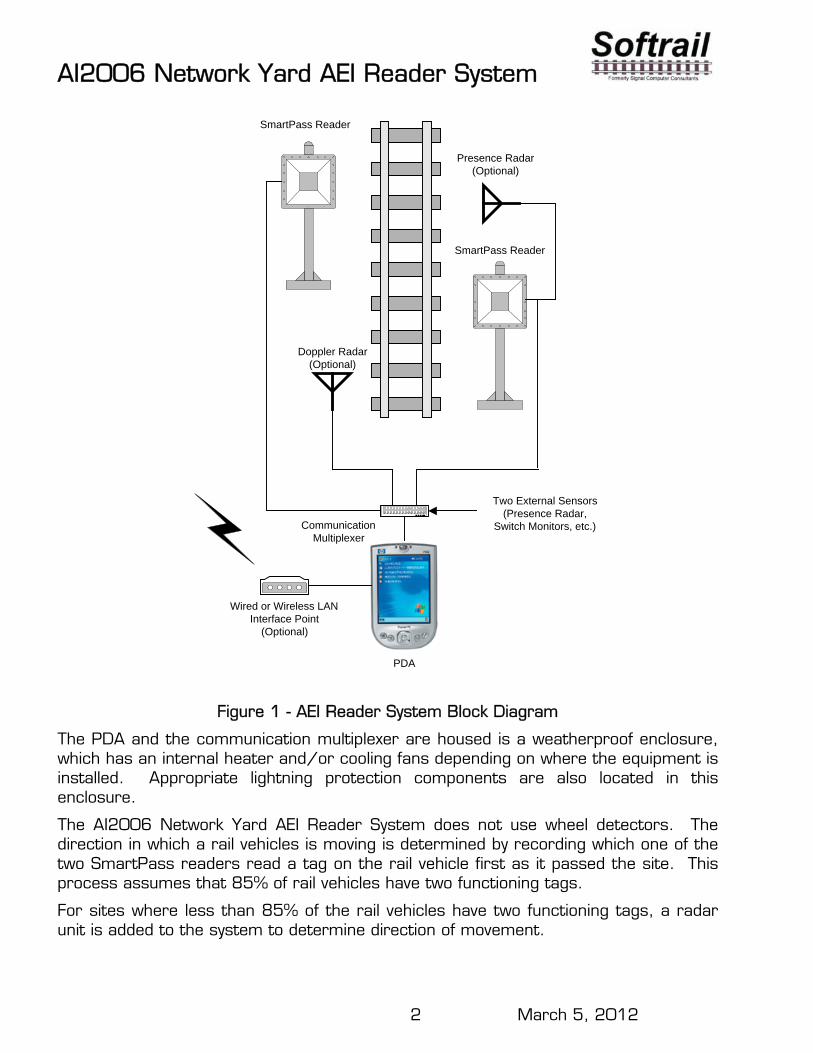
A commercial HP iPAQ PDA running Windows Mobile 5 operating system A communication multiplexer Two SmartPass 4 AEI readers Figure 1 is a block diagram of the AEI reader system.
AI2006 Network Yard AEI Reader System
2 March 5, 2012
Wired or Wireless LANInterface Point
(Optional)
CommunicationMultiplexer
SmartPass Reader
SmartPass Reader
Doppler Radar(Optional)
PDA
Presence Radar(Optional)
Two External Sensors(Presence Radar,
Switch Monitors, etc.)
Figure 1 - AEI Reader System Block Diagram
The PDA and the communication multiplexer are housed is a weatherproof enclosure, which has an internal heater and/or cooling fans depending on where the equipment is installed. Appropriate lightning protection components are also located in this enclosure.
The AI2006 Network Yard AEI Reader System does not use wheel detectors. The direction in which a rail vehicles is moving is determined by recording which one of the two SmartPass readers read a tag on the rail vehicle first as it passed the site. This process assumes that 85% of rail vehicles have two functioning tags.
For sites where less than 85% of the rail vehicles have two functioning tags, a radar unit is added to the system to determine direction of movement.

AI2006 Network Yard AEI Reader System
3 March 5, 2012
The radar unit in conjunction with a presence loop also allows the system to detect untagged rail vehicles.
Because the system does not use wheel detectors and has very few components, it is very reliable and easy to maintain.
One of the key features of this system is that it is constantly monitoring itself. If it detects a problem, it sends emails describing the problem to a list of up to seven individuals. When the problem is corrected, it will send emails stating that the problem has been resolved. The status of the system is also included in the body of emails that report rail vehicle movements past the site.
If, for example, the system detects that one of the SmartPass readers is failing, it will notify a maintainer by email. The maintainer will replace the SmartPass reader with a spare, which requires only one cable connection and a couple of mounting bolts. When the AEI reader system detects the new SmartPass reader, it will automatically configure it and send emails stating that the problem has been resolved.
2. EQUIPMENT INSTALLATION
2.1. Deliverables
The Network Yard Reader System shipment contains the following items:
Two SmartPass 4 readers with pole mounting brackets One Controller (which includes the HP iPAQ PDA and communication multiplexer)
housed in a fiberglass weatherproof enclosure with an internal heater One mounting bracket for the fiberglass weatherproof enclosure Two SmartPass cables (one approximately 5 feet long and the other approximately
35 feet long) HP iPAQ PDA box with manuals, software and cradle (the PDA is installed in the
Controller) Two test AEI tags
2.2. SmartPass Reader Installation
The two SmartPass readers should be mounted on poles on the opposite sides of the track. They should be mounted across from each other (+/- 5 feet) and 11 feet from the center of the rail. The center of each SmartPass reader should be 3 ½ feet above the top of the rail. The readers should be pointing toward the track.
A conduit should be placed under the rail for the longer SmartPass reader cable.
The two SmartPass reader cables should be attached to the SmartPass readers, circular connectors.

AI2006 Network Yard AEI Reader System
4 March 5, 2012
2.3. Controller Installation
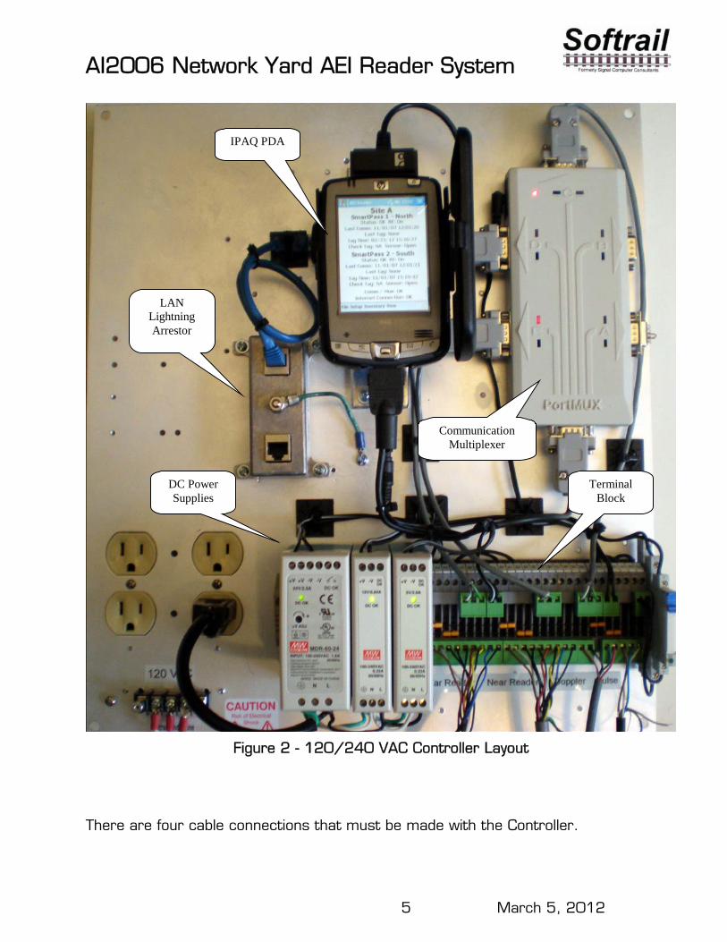
The Controller should be mounted on the same pole as one of the SmartPass readers, but on the opposite side of the pole from the SmartPass reader. It can be mounted at any convenient height on the pole. See the picture in Figure 2.
There are seven main components in the Controller. These are:
HP iPAQ PDA Communication Multiplexer Terminal Block LAN Lightning Arrestor (optional) 24 VDC Power Supply (used for the SmartPass readers) 12 VDC Power Supply or 24 VDC to 12 VDC converter (used for the
Communication Multiplexer and the Optional Radars) 5 VDC Power Supply or 24 VDC to 5 VDC converters (used for the PDA)
The 120/240 VAC version of the system uses 24 VDC, 12 VDC and 5 VDC power supplies. The 24 VDC version of the system uses 24 VDC to 12 VDC and 24 VDC to 5 VDC converters.
Figure 2 shows the layout of the 120/240 VAC version of the controller.
The 24 VDC version of the system is used when there is a battery backup system or when the system is solar powered.
AI2006 Network Yard AEI Reader System
5 March 5, 2012
IPAQ PDA
LAN Lightning Arrestor
DC Power Supplies
Communication Multiplexer
Terminal Block
Figure 2 - 120/240 VAC Controller Layout
There are four cable connections that must be made with the Controller.

AI2006 Network Yard AEI Reader System
6 March 5, 2012
The SmartPass cables connect to the bottom of the SmartPass Terminal Block in the Controller's enclosure (see
Figure 3). Each cable has 6 pairs of wires, but only five pairs are currently used. The green/black pair is not used.
Far SmartPass Reader Cable
Near SmartPassReader Cable
Stalker Doppler Radar Cable
QT50R PresenceRadar Cable
Figure 3 - Terminal Block
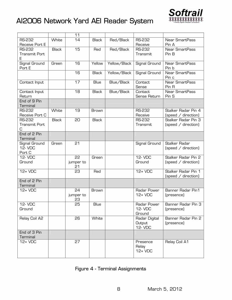
The other five pairs of each cable are connected to 9 terminals. The yellow and black wires of the yellow/black pair are tied together and share one terminal.
The SmartPass cable from the far SmartPass reader uses the left most 9 terminals and the SmartPass cable from the near SmartPass reader uses the next 9 terminals (going left to right). The next five terminals to the right (only four are used) are used to connect with the Doppler radar if this option is included. The last three terminals are connected to the optional QT50R presence radar.

AI2006 Network Yard AEI Reader System
7 March 5, 2012
The cables are shipped with the plug-in connectors attached. These can be removed to pull the cables through conduit. The SmartPass cables should be cut so that slack is removed.
The following are the cable assignments for the SmartPass terminal block:
SmartPass Terminal Block Cable Assignments Terminals are numbered from left to right.
Description System Side
Wire Color
Terminal Number
Wire Color
Pair Color Description SmartPass
Side
SmartPass Cable
Pin Assignments 24+ VDC 1 Brown Brown/Black 24 VAC
Return Far SmartPass Pin J
24+ VDC 2 jumper to
1
White White/Black 24 VAC Return
Far SmartPass Pin G
24- VDC 3 Black Brown/Black 24 VAC Far SmartPass Pin K
24- VDC 4 jumper to
3
Black White/Black 24 VAC Far SmartPass Pin H
RS-232 Receive Port D
White 5 Black Red/Black RS-232 Receive
Far SmartPass Pin A
RS-232 Transmit Port D
Black 6 Red Red/Black RS-232 Transmit
Far SmartPass Pin B
Signal Ground Port D
Green 7 Yellow Yellow/Black Signal Ground Far SmartPass Pin b
7 Black Yellow/Black Signal Ground Far SmartPass Pin c
Contact Input 8 Blue Blue/Black Contact Sense
Far SmartPass Pin R
Contact Input Return
9 Black Blue/Black Contact Sense Return
Far SmartPass Pin S
End of 9 Pin Terminal
24+ VDC 10
Brown Brown/Black 24 VAC Return
Near SmartPass Pin J
24+ VDC 11 jumper to
10
White White/Black 24 VAC Return
Near SmartPass Pin G
24- VDC 12 Black Brown/Black 24 VAC Near SmartPass Pin K
24- VDC 13 jumper to
Black White/Black 24 VAC Near SmartPass Pin H
AI2006 Network Yard AEI Reader System
8 March 5, 2012
11 RS-232 Receive Port E
White 14 Black Red/Black RS-232 Receive
Near SmartPass Pin A
RS-232 Transmit Port E
Black 15 Red Red/Black RS-232 Transmit
Near SmartPass Pin B
Signal Ground Port E
Green 16 Yellow Yellow/Black Signal Ground Near SmartPass Pin b
16 Black Yellow/Black Signal Ground Near SmartPass Pin c
Contact Input 17 Blue Blue/Black Contact Sense
Near SmartPass Pin R
Contact Input Return
18 Black Blue/Black Contact Sense Return
Near SmartPass Pin S
End of 9 Pin Terminal
RS-232 Receive Port C
White 19 Brown
RS-232 Receive
Stalker Radar Pin 4 (speed / direction)
RS-232 Transmit Port C
Black 20 Black RS-232 Transmit
Stalker Radar Pin 3 (speed / direction)
End of 2 Pin Terminal
Signal Ground 12- VDC Port C
Green 21 Signal Ground Stalker Radar (speed / direction)
12- VDC Ground
22 jumper to
21
Green 12- VDC Ground
Stalker Radar Pin 2 (speed / direction)
12+ VDC 23 Red 12+ VDC Stalker Radar Pin 1 (speed / direction)
End of 2 Pin Terminal
12+ VDC 24 jumper to
23
Brown Radar Power 12+ VDC
Banner Radar Pin1 (presence)
12- VDC Ground
25 Blue Radar Power 12- VDC Ground
Banner Radar Pin 3 (presence)
Relay Coil A2 26 White Radar Digital Output 12- VDC
Banner Radar Pin 2 (presence)
End of 3 Pin Terminal
12+ VDC
27 Presence Relay 12+ VDC
Relay Coil A1
Figure 4 - Terminal Assignments
AI2006 Network Yard AEI Reader System
9 March 5, 2012
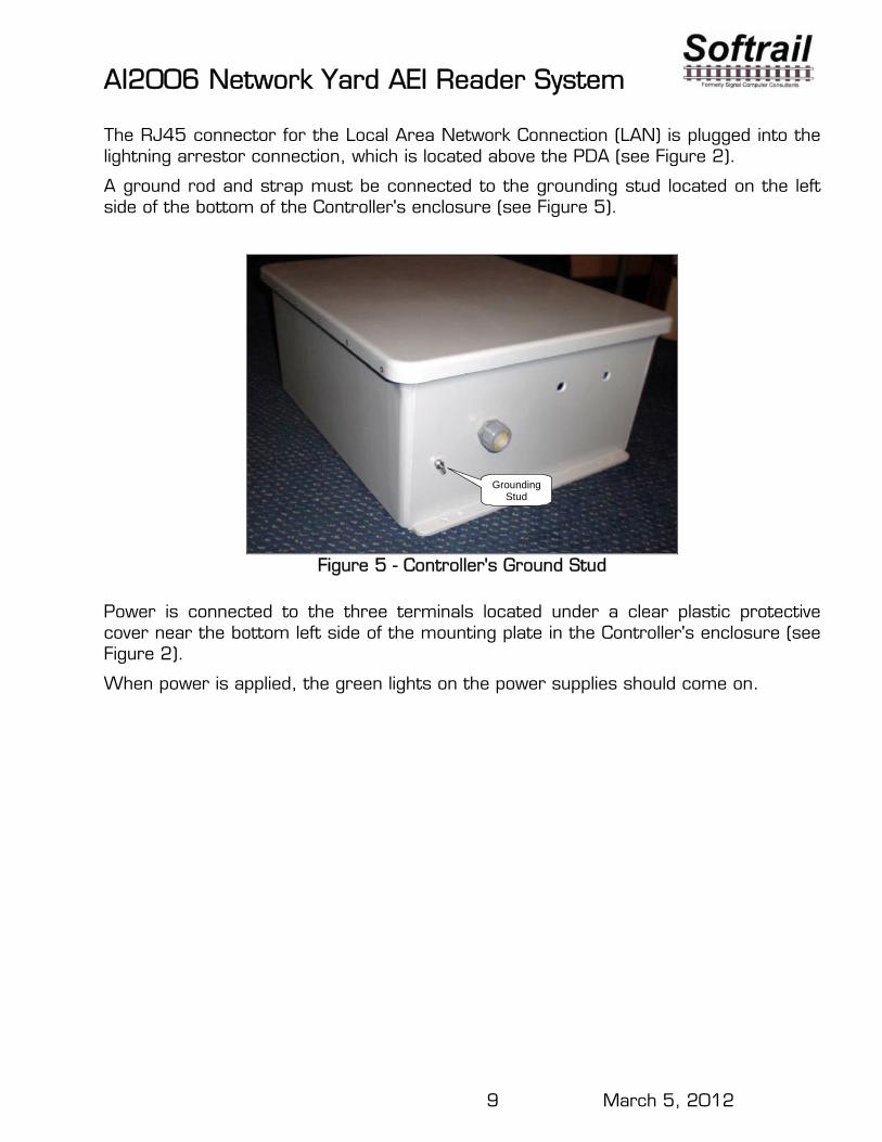
The RJ45 connector for the Local Area Network Connection (LAN) is plugged into the lightning arrestor connection, which is located above the PDA (see Figure 2).
A ground rod and strap must be connected to the grounding stud located on the left side of the bottom of the Controller's enclosure (see Figure 5).
Grounding Stud
Figure 5 - Controller's Ground Stud
Power is connected to the three terminals located under a clear plastic protective cover near the bottom left side of the mounting plate in the Controller's enclosure (see Figure 2).
When power is applied, the green lights on the power supplies should come on.
AI2006 Network Yard AEI Reader System
10 March 5, 2012
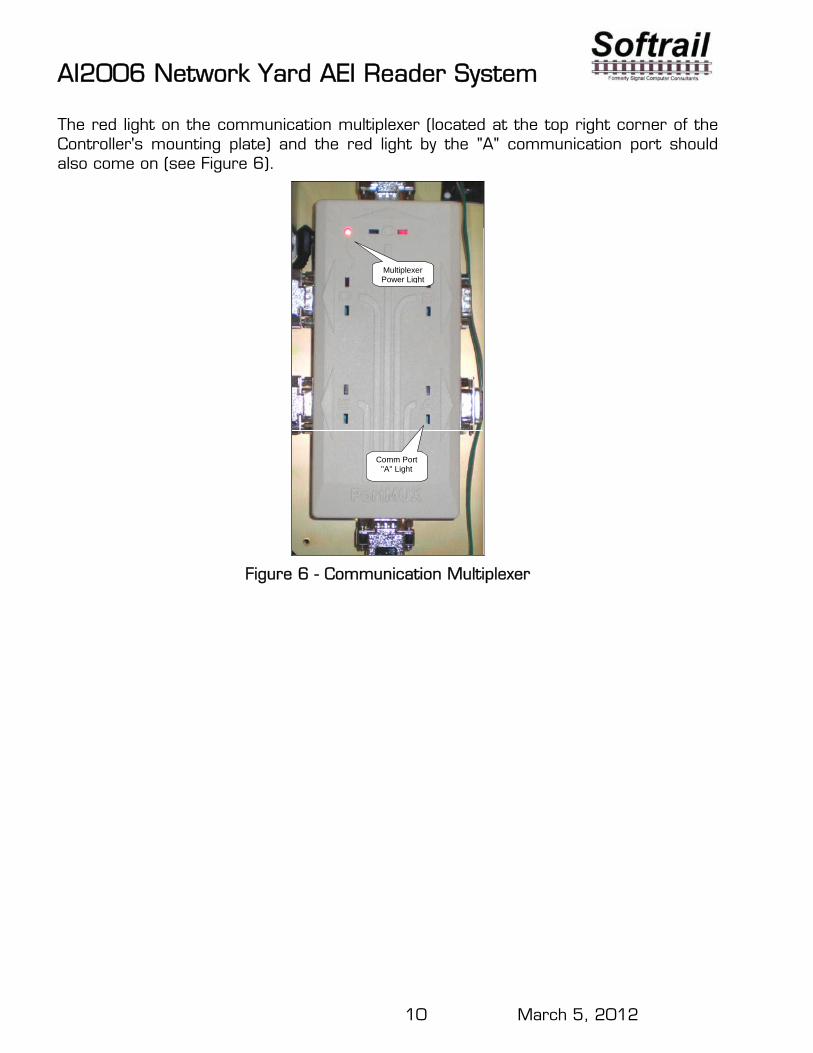
The red light on the communication multiplexer (located at the top right corner of the Controller's mounting plate) and the red light by the "A" communication port should also come on (see Figure 6).
Comm Port "A" Light
Multiplexer Power Light
Figure 6 - Communication Multiplexer
AI2006 Network Yard AEI Reader System
11 March 5, 2012
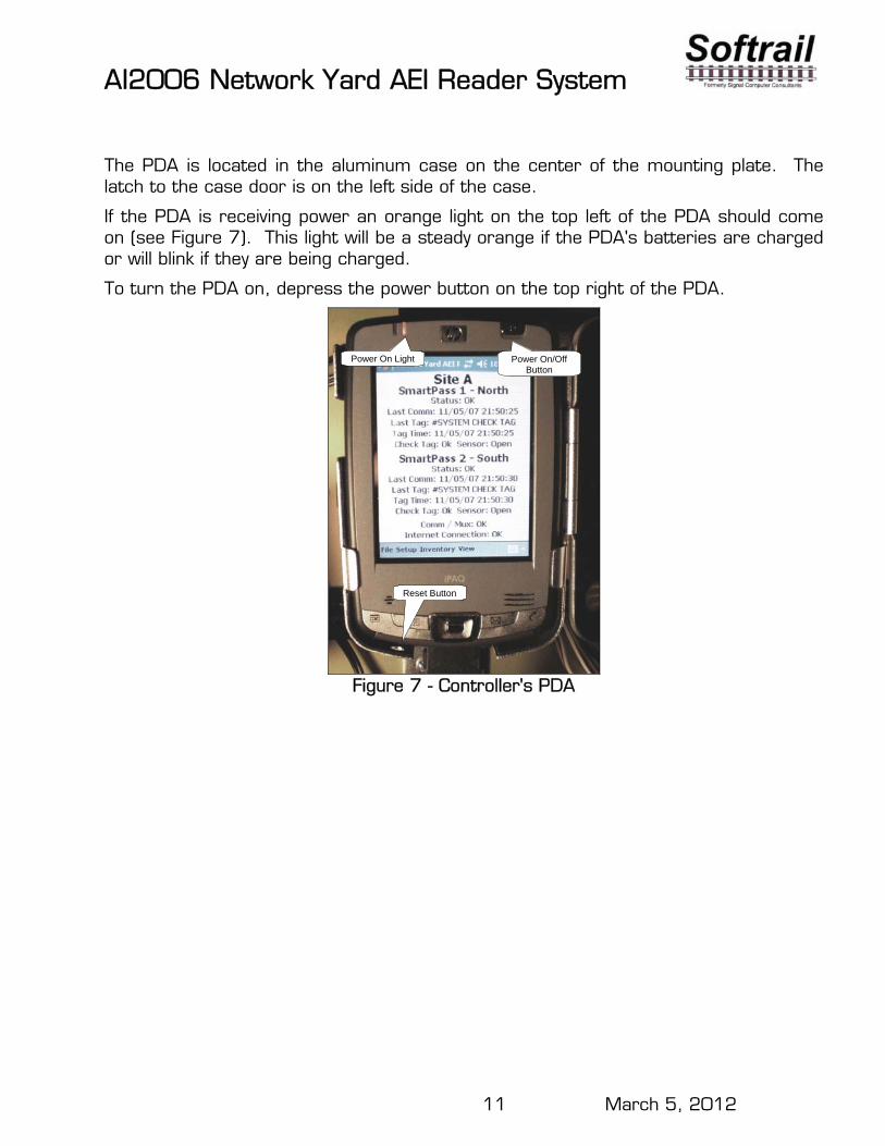
The PDA is located in the aluminum case on the center of the mounting plate. The latch to the case door is on the left side of the case.
If the PDA is receiving power an orange light on the top left of the PDA should come on (see Figure 7). This light will be a steady orange if the PDA's batteries are charged or will blink if they are being charged.
To turn the PDA on, depress the power button on the top right of the PDA.
Reset Button
Power On Light Power On/Off Button
Figure 7 - Controller's PDA
AI2006 Network Yard AEI Reader System
12 March 5, 2012
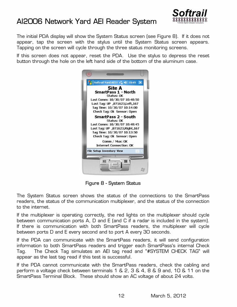
The initial PDA display will show the System Status screen (see Figure 8). If it does not appear, tap the screen with the stylus until the System Status screen appears. Tapping on the screen will cycle through the three status monitoring screens.
If this screen does not appear, reset the PDA. Use the stylus to depress the reset button through the hole on the left hand side of the bottom of the aluminum case.
Figure 8 - System Status
The System Status screen shows the status of the connections to the SmartPass readers, the status of the communication multiplexer, and the status of the connection to the internet.
If the multiplexer is operating correctly, the red lights on the multiplexer should cycle between communication ports A, D and E (and C if a radar is included in the system). If there is communication with both SmartPass readers, the multiplexer will cycle between ports D and E every second and to port A every 30 seconds.
If the PDA can communicate with the SmartPass readers, it will send configuration information to both SmartPass readers and trigger each SmartPass's internal Check Tag. The Check Tag simulates an AEI tag read and "#SYSTEM CHECK TAG" will appear as the last tag read if this test is successful.
If the PDA cannot communicate with the SmartPass readers, check the cabling and perform a voltage check between terminals 1 & 2, 3 & 4, 8 & 9 and, 10 & 11 on the SmartPass Terminal Block. These should show an AC voltage of about 24 volts.
AI2006 Network Yard AEI Reader System
13 March 5, 2012
There are two test AEI tags shipped with the equipment. Wave one tag in front of the near SmartPass reader. The tag data should be displayed for "SmartPass 1 – North" on the screen. Wave the same tag in front of the far SmartPass Reader. Tag data should be displayed for the "SmartPass 2 – South" on the screen.
Waving a tag in front of both readers will cause a rail vehicle movement report to be generated and emailed to the email addresses entered into the PDA (go to the Setup/Email Addresses menu item to enter email addresses to receive rail vehicle movement reports).
If the tag is waved in front of the North SmartPass reader first, the rail vehicle will be reported as moving west. If it is waved in front of the South SmartPass reader first, it will be reported as moving east.
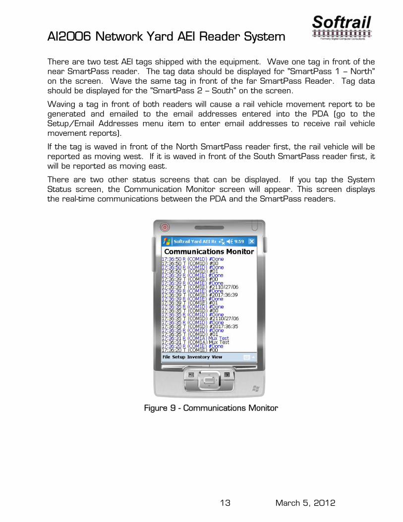
There are two other status screens that can be displayed. If you tap the System Status screen, the Communication Monitor screen will appear. This screen displays the real-time communications between the PDA and the SmartPass readers.
Figure 9 - Communications Monitor
AI2006 Network Yard AEI Reader System
14 March 5, 2012
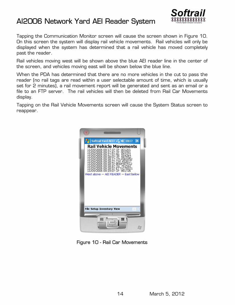
Tapping the Communication Monitor screen will cause the screen shown in Figure 10. On this screen the system will display rail vehicle movements. Rail vehicles will only be displayed when the system has determined that a rail vehicle has moved completely past the reader.
Rail vehicles moving west will be shown above the blue AEI reader line in the center of the screen, and vehicles moving east will be shown below the blue line.
When the PDA has determined that there are no more vehicles in the cut to pass the reader (no rail tags are read within a user selectable amount of time, which is usually set for 2 minutes), a rail movement report will be generated and sent as an email or a file to an FTP server. The rail vehicles will then be deleted from Rail Car Movements display.
Tapping on the Rail Vehicle Movements screen will cause the System Status screen to reappear.
Figure 10 - Rail Car Movements
AI2006 Network Yard AEI Reader System
15 March 5, 2012
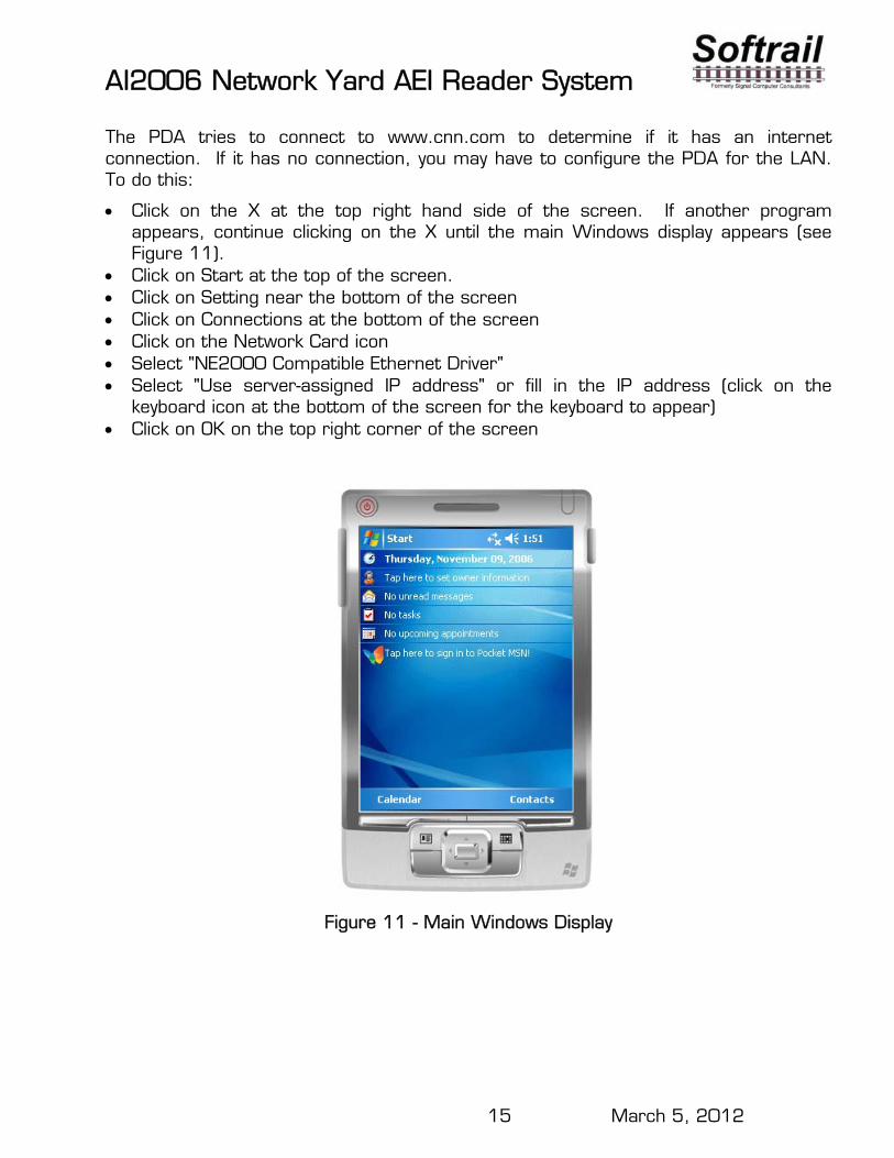
The PDA tries to connect to www.cnn.com to determine if it has an internet connection. If it has no connection, you may have to configure the PDA for the LAN. To do this:
Click on the X at the top right hand side of the screen. If another program appears, continue clicking on the X until the main Windows display appears (see Figure 11).
Click on Start at the top of the screen. Click on Setting near the bottom of the screen Click on Connections at the bottom of the screen Click on the Network Card icon Select "NE2000 Compatible Ethernet Driver" Select "Use server-assigned IP address" or fill in the IP address (click on the
keyboard icon at the bottom of the screen for the keyboard to appear) Click on OK on the top right corner of the screen
Figure 11 - Main Windows Display
AI2006 Network Yard AEI Reader System
16 March 5, 2012
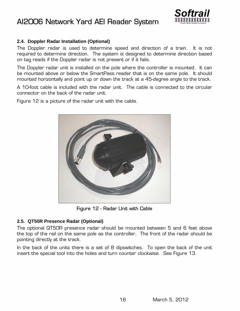
2.4. Doppler Radar Installation (Optional)
The Doppler radar is used to determine speed and direction of a train. It is not required to determine direction. The system is designed to determine direction based on tag reads if the Doppler radar is not present or if it fails.
The Doppler radar unit is installed on the pole where the controller is mounted. It can be mounted above or below the SmartPass reader that is on the same pole. It should mounted horizontally and point up or down the track at a 45-degree angle to the track.
A 10-foot cable is included with the radar unit. The cable is connected to the circular connector on the back of the radar unit.
Figure 12 is a picture of the radar unit with the cable.
Figure 12 - Radar Unit with Cable
2.5. QT50R Presence Radar (Optional)
The optional QT50R presence radar should be mounted between 5 and 6 feet above the top of the rail on the same pole as the controller. The front of the radar should be pointing directly at the track.
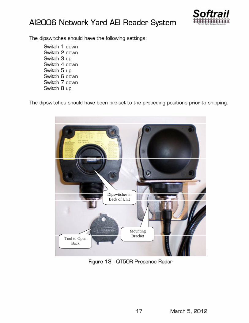
In the back of the units there is a set of 8 dipswitches. To open the back of the unit insert the special tool into the holes and turn counter clockwise. See Figure 13.
AI2006 Network Yard AEI Reader System
17 March 5, 2012
The dipswitches should have the following settings:
Switch 1 down Switch 2 down Switch 3 up Switch 4 down Switch 5 up Switch 6 down Switch 7 down Switch 8 up
The dipswitches should have been pre-set to the preceding positions prior to shipping.
Dipswitches in Back of Unit
Tool to Open Back
Mounting Bracket
Figure 13 - QT50R Presence Radar
AI2006 Network Yard AEI Reader System
18 March 5, 2012
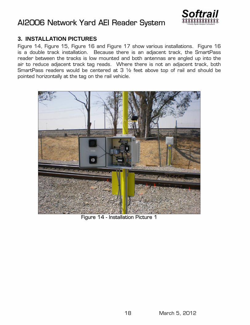
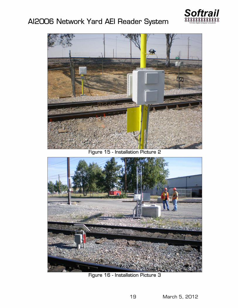
3. INSTALLATION PICTURES Figure 14, Figure 15, Figure 16 and Figure 17 show various installations. Figure 16 is a double track installation. Because there is an adjacent track, the SmartPass reader between the tracks is low mounted and both antennas are angled up into the air to reduce adjacent track tag reads. Where there is not an adjacent track, both SmartPass readers would be centered at 3 ½ feet above top of rail and should be pointed horizontally at the tag on the rail vehicle.
Figure 14 - Installation Picture 1
AI2006 Network Yard AEI Reader System
19 March 5, 2012
Figure 15 - Installation Picture 2
Figure 16 - Installation Picture 3

AI2006 Network Yard AEI Reader System
20 March 5, 2012
Figure 17 - Installation Picture 4
AI2006 Network Yard AEI Reader System
21 March 5, 2012
4. CONFIGURATION PARAMETERS The AI2006 Network Yard AEI Reader has a number of configuration parameters that need to be set up. Most of the configuration parameters are for identifying the AEI Reader Site and communicating with other systems via email or an FTP server. These configuration parameters are entered into the system by selecting the Setup menu at the bottom of the PDA's screen.
Setting up the configuration parameters includes:
Entering contact information that will appear in emails Identifying the AEI reader site by entering the T94 AEM name Selecting how AEI data is sent and in which format (text or T94 files) Setting the AEI reader site's track orientation (North/South, West/East) Setting the AEI reader site's tag filter parameters Setting the SmartPass readers' parameters Setting the FTP server address, user name and password Setting the email outgoing server address, user name and password Entering the email addresses where various types of emails will be sent Entering TCP/IP information for communicating with the AEI Rail and Road
Manager program Setting the radar configuration parameters Setting a URL for checking the connection to the internet Specifying the internal folders where OEM applications can retrieve AEI data and
send emails or files to an FTP server
AI2006 Network Yard AEI Reader System
22 March 5, 2012
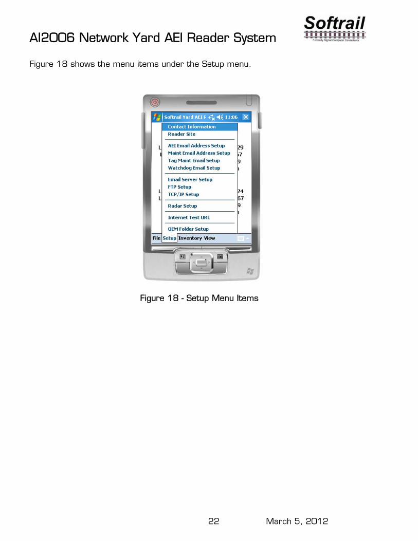
Figure 18 shows the menu items under the Setup menu.
Figure 18 - Setup Menu Items
AI2006 Network Yard AEI Reader System
23 March 5, 2012
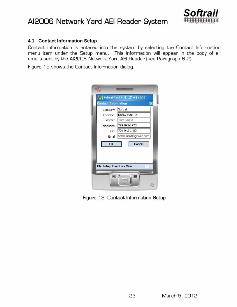
4.1. Contact Information Setup
Contact information is entered into the system by selecting the Contact Information menu item under the Setup menu. This information will appear in the body of all emails sent by the AI2006 Network Yard AEI Reader (see Paragraph 6.2).
Figure 19 shows the Contact Information dialog.
Figure 19- Contact Information Setup
AI2006 Network Yard AEI Reader System
24 March 5, 2012
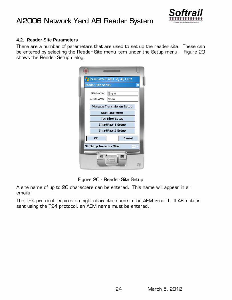
4.2. Reader Site Parameters
There are a number of parameters that are used to set up the reader site. These can be entered by selecting the Reader Site menu item under the Setup menu. Figure 20 shows the Reader Setup dialog.
Figure 20 - Reader Site Setup
A site name of up to 20 characters can be entered. This name will appear in all emails.
The T94 protocol requires an eight-character name in the AEM record. If AEI data is sent using the T94 protocol, an AEM name must be entered.
AI2006 Network Yard AEI Reader System
25 March 5, 2012
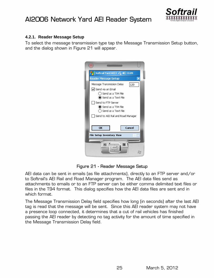
4.2.1. Reader Message Setup
To select the message transmission type tap the Message Transmission Setup button, and the dialog shown in Figure 21 will appear.
Figure 21 - Reader Message Setup
AEI data can be sent in emails (as file attachments), directly to an FTP server and/or to Softrail's AEI Rail and Road Manager program. The AEI data files send as attachments to emails or to an FTP server can be either comma delimited text files or files in the T94 format. This dialog specifies how the AEI data files are sent and in which format.
The Message Transmission Delay field specifies how long (in seconds) after the last AEI tag is read that the message will be sent. Since this AEI reader system may not have a presence loop connected, it determines that a cut of rail vehicles has finished passing the AEI reader by detecting no tag activity for the amount of time specified in the Message Transmission Delay field.
AI2006 Network Yard AEI Reader System
26 March 5, 2012
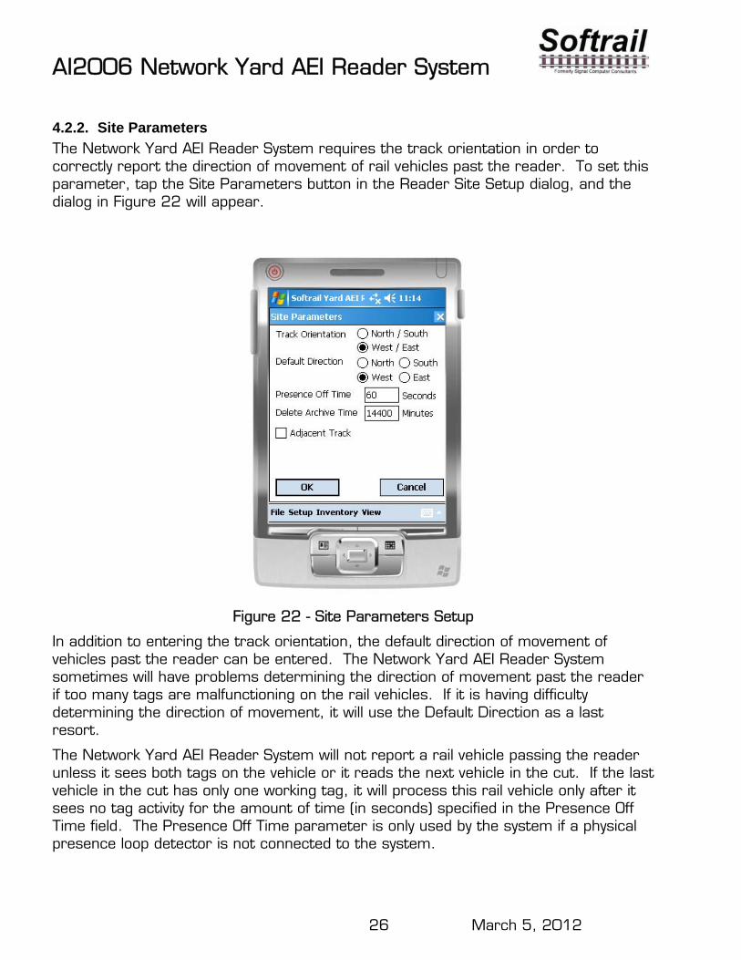
4.2.2. Site Parameters
The Network Yard AEI Reader System requires the track orientation in order to correctly report the direction of movement of rail vehicles past the reader. To set this parameter, tap the Site Parameters button in the Reader Site Setup dialog, and the dialog in Figure 22 will appear.
Figure 22 - Site Parameters Setup
In addition to entering the track orientation, the default direction of movement of vehicles past the reader can be entered. The Network Yard AEI Reader System sometimes will have problems determining the direction of movement past the reader if too many tags are malfunctioning on the rail vehicles. If it is having difficulty determining the direction of movement, it will use the Default Direction as a last resort.
The Network Yard AEI Reader System will not report a rail vehicle passing the reader unless it sees both tags on the vehicle or it reads the next vehicle in the cut. If the last vehicle in the cut has only one working tag, it will process this rail vehicle only after it sees no tag activity for the amount of time (in seconds) specified in the Presence Off Time field. The Presence Off Time parameter is only used by the system if a physical presence loop detector is not connected to the system.
AI2006 Network Yard AEI Reader System
27 March 5, 2012
The system keeps track of rail vehicles it previously read in an Archive file. If the system is having problems determining the direction a rail vehicle, it will check the Archive file to see if it read the vehicle before. If it finds a record for the vehicle, it will use the direction that is opposite the last reported direction in the Archive file.
This feature is useful when the reader system is placed at the rail gate of a yard. The assumption is that if its last read shows the rail vehicle going into the yard, then the next read of the rail vehicle should show it moving out of the yard.
The Delete Archive Time parameter specifies how long an archived record will be used. Records older than the number of minutes entered into this field will not be used. If this parameter is set to 0 minutes, then the Archive file is not searched since all records are older than 0 minutes.
If there is a track adjacent to the track being read by the system and it is close enough that (less than 24 feet center of track to center of track) the system could read tags on rail vehicles on the adjacent track, then the Adjacent Track box should be checked. The system uses this parameter to filter out adjacent track tag reads and to disable some tag performance warning messages.
4.2.3. Tag Filter Setup
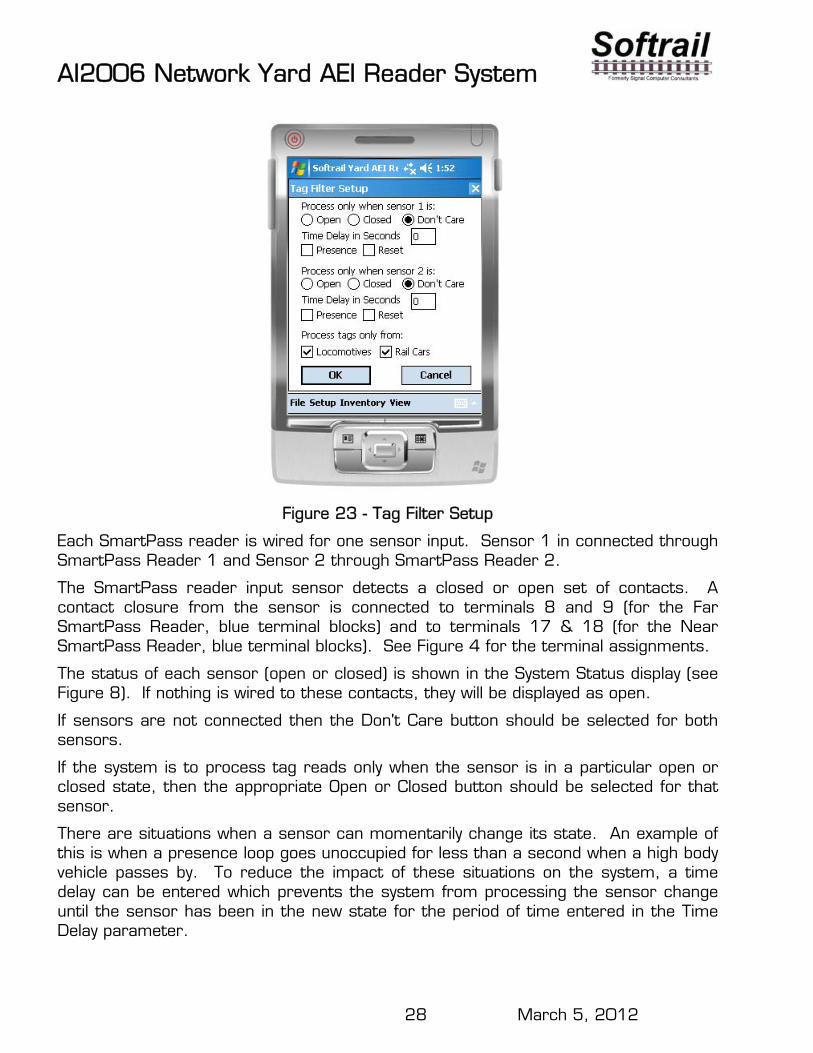
The Network Yard AEI Reader System can be configured to ignore tag reads based on sensor input or tag type. To configure the system to filter out tag reads tap the Tag Filter Setup button on the Reader Site Setup dialog. This will cause the Tag Filter Setup dialog in Figure 23 to be displayed.
AI2006 Network Yard AEI Reader System
28 March 5, 2012
Figure 23 - Tag Filter Setup
Each SmartPass reader is wired for one sensor input. Sensor 1 in connected through SmartPass Reader 1 and Sensor 2 through SmartPass Reader 2.
The SmartPass reader input sensor detects a closed or open set of contacts. A contact closure from the sensor is connected to terminals 8 and 9 (for the Far SmartPass Reader, blue terminal blocks) and to terminals 17 & 18 (for the Near SmartPass Reader, blue terminal blocks). See Figure 4 for the terminal assignments.
The status of each sensor (open or closed) is shown in the System Status display (see Figure 8). If nothing is wired to these contacts, they will be displayed as open.
If sensors are not connected then the Don't Care button should be selected for both sensors.
If the system is to process tag reads only when the sensor is in a particular open or closed state, then the appropriate Open or Closed button should be selected for that sensor.
There are situations when a sensor can momentarily change its state. An example of this is when a presence loop goes unoccupied for less than a second when a high body vehicle passes by. To reduce the impact of these situations on the system, a time delay can be entered which prevents the system from processing the sensor change until the sensor has been in the new state for the period of time entered in the Time Delay parameter.
AI2006 Network Yard AEI Reader System
29 March 5, 2012
If one of the sensors is a presence loop, then the Presence box should be checked for that sensor and the appropriate Open or Closed button that indicates when the presence loop is occupied selected.
In most cases, the system should reset its internal variables when a new cut of rail vehicles is being processed. The Reset box should be checked any time the system is to start processing a new cut of rail vehicles based on the sensor input.
The system can also be configured to only process railcar or locomotive tags.

AI2006 Network Yard AEI Reader System
30 March 5, 2012
4.2.4. SmartPass Reader Parameters
Each of the two SmartPass readers has individual parameters that can be set. There are two buttons (one for each SmartPass reader) that can be tapped on the Reader Site Setup dialog. Tapping the SmartPass 1 Setup or the SmartPass 2 Setup button will cause the SmartPass Setup dialog in Figure 24 to be displayed for the selected reader.
Figure 24 - SmartPass Setup
Each SmartPass reader is wired to one of the Communication Multiplexer's ports. Comm Port assignments should not be changed unless there is a problem with the multiplexer. SmartPass Reader 1 is normally assigned to Port D and SmartPass Reader 2 to Port E.
Each SmartPass reader must to be assigned its own frequency and have a minimum frequency separation of 2.5 MHz from the nearest SmartPass reader that is within 100 feet. The Network Yard AEI Reader System will automatically assign a frequency of 913 MHz to SmartPass Reader 1 and 917 MHz to SmartPass Reader 2. These frequencies will be periodically downloaded to the SmartPass readers. If a SmartPass reader is replaced, the Network Yard AEI Reader System will automatically configure the new SmartPass reader to the assigned frequency.
To determine the direction of movement of rail vehicles past a reader, the Network Yard AEI Reader System must know which side of the track each SmartPass reader is
AI2006 Network Yard AEI Reader System
31 March 5, 2012
on. If the track orientation is West/East, then one of the readers (usually SmartPass Reader 1) is identified to be on the North side of the track and other on the South side.
The SmartPass reader's serial number will appear in this dialog after the Network Yard AEI reader System retrieves this data from the SmartPass reader.
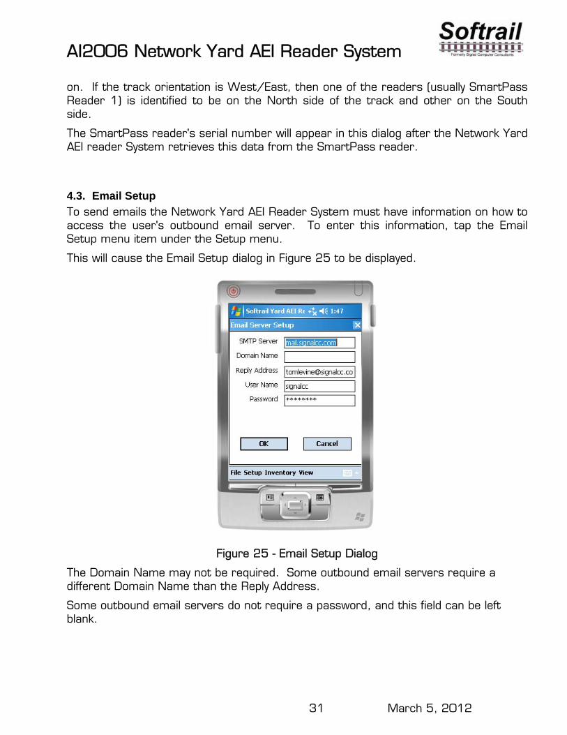
4.3. Email Setup
To send emails the Network Yard AEI Reader System must have information on how to access the user's outbound email server. To enter this information, tap the Email Setup menu item under the Setup menu.
This will cause the Email Setup dialog in Figure 25 to be displayed.
Figure 25 - Email Setup Dialog
The Domain Name may not be required. Some outbound email servers require a different Domain Name than the Reply Address.
Some outbound email servers do not require a password, and this field can be left blank.
AI2006 Network Yard AEI Reader System
32 March 5, 2012
The reply address entered in this dialog is used as the reply address for all outbound emails. Some servers require that this be a valid email address for the user of the server.
The Network Yard AEI Reader System does not receive inbound emails.
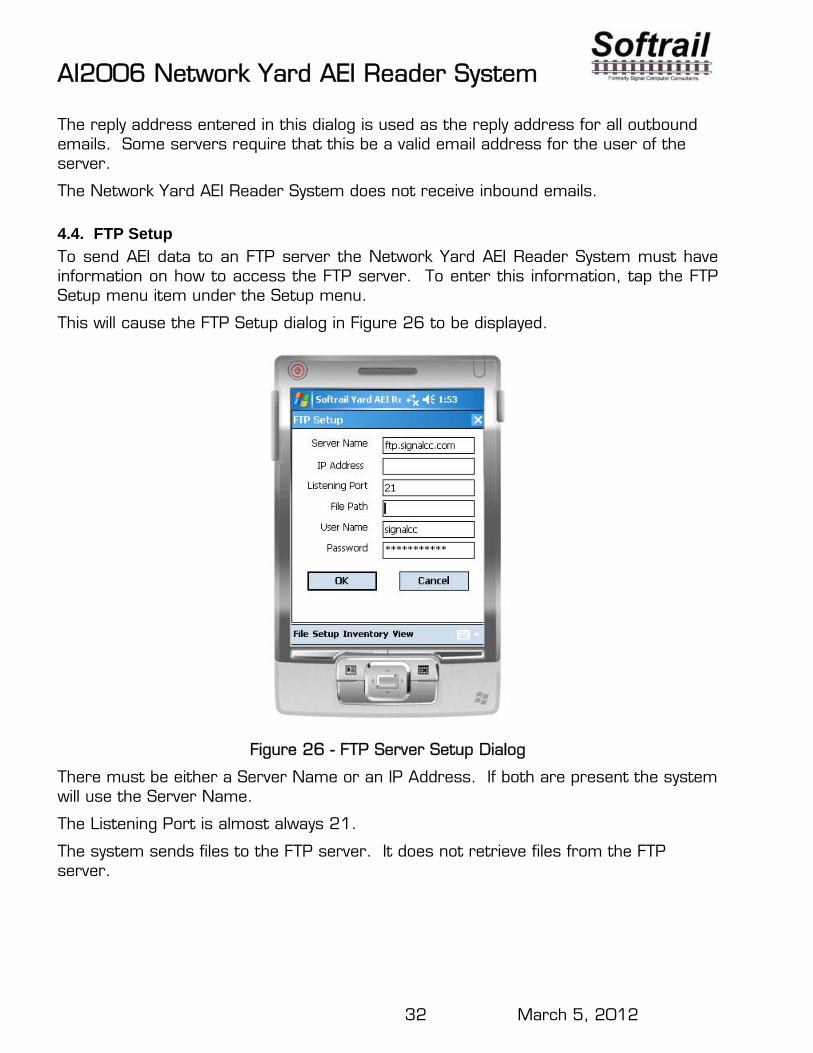
4.4. FTP Setup
To send AEI data to an FTP server the Network Yard AEI Reader System must have information on how to access the FTP server. To enter this information, tap the FTP Setup menu item under the Setup menu.
This will cause the FTP Setup dialog in Figure 26 to be displayed.
Figure 26 - FTP Server Setup Dialog
There must be either a Server Name or an IP Address. If both are present the system will use the Server Name.
The Listening Port is almost always 21.
The system sends files to the FTP server. It does not retrieve files from the FTP server.
AI2006 Network Yard AEI Reader System
33 March 5, 2012
4.5. TCP/IP Setup
The Network Yard AEI Reader System is designed to work in conjunction with Softrail's AEI Rail and Road Manager program.
The AEI Rail & Road Manager software was designed as a low cost package for tracking rail vehicle movements in a rail yard. This is a Windows-based program that can run under the Windows 98, NT, 2000, ME, or XP operating systems. The AEI Rail & Road Manager software program allows the user to draw his/her own facility and move rail cars by reading their tags with a wayside AEI reader, portable AEI reader or manually by dragging and dropping rail car icons from one track to another. By using input from wayside AEI readers, the program can also automatically track rail car movements.
For more information about this program go to Softrail's web page at www.aeitag.com.
To send track data to the AEI Rail and Road manager program the Network Yard AEI Reader System needs to know the IP address of the computer hosting the AEI Rail and Road Manager program and the port to which the program is listening for a connection.
The listening port is a setup parameter in the AEI Rail and Road Manager program. The default Server Port is 2101.
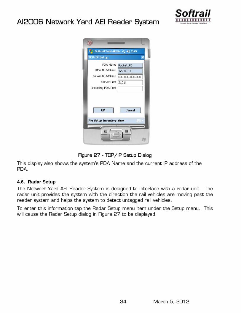
To enter this information tap the TCP/IP Setup menu item under the Setup menu. This will cause the TCP/IP Setup dialog to be displayed.
AI2006 Network Yard AEI Reader System
34 March 5, 2012
Figure 27 - TCP/IP Setup Dialog
This display also shows the system's PDA Name and the current IP address of the PDA.
4.6. Radar Setup
The Network Yard AEI Reader System is designed to interface with a radar unit. The radar unit provides the system with the direction the rail vehicles are moving past the reader system and helps the system to detect untagged rail vehicles.
To enter this information tap the Radar Setup menu item under the Setup menu. This will cause the Radar Setup dialog in Figure 27 to be displayed.
AI2006 Network Yard AEI Reader System
35 March 5, 2012
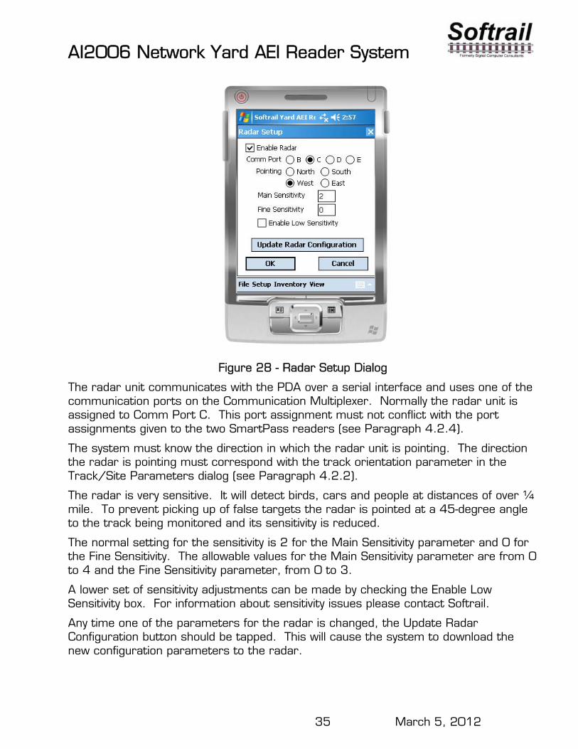
Figure 28 - Radar Setup Dialog
The radar unit communicates with the PDA over a serial interface and uses one of the communication ports on the Communication Multiplexer. Normally the radar unit is assigned to Comm Port C. This port assignment must not conflict with the port assignments given to the two SmartPass readers (see Paragraph 4.2.4).
The system must know the direction in which the radar unit is pointing. The direction the radar is pointing must correspond with the track orientation parameter in the Track/Site Parameters dialog (see Paragraph 4.2.2).
The radar is very sensitive. It will detect birds, cars and people at distances of over ¼ mile. To prevent picking up of false targets the radar is pointed at a 45-degree angle to the track being monitored and its sensitivity is reduced.
The normal setting for the sensitivity is 2 for the Main Sensitivity parameter and 0 for the Fine Sensitivity. The allowable values for the Main Sensitivity parameter are from 0 to 4 and the Fine Sensitivity parameter, from 0 to 3.
A lower set of sensitivity adjustments can be made by checking the Enable Low Sensitivity box. For information about sensitivity issues please contact Softrail.
Any time one of the parameters for the radar is changed, the Update Radar Configuration button should be tapped. This will cause the system to download the new configuration parameters to the radar.
AI2006 Network Yard AEI Reader System
36 March 5, 2012
4.7. Emails Addresses
The Network Yard AEI Reader System communicates a great deal of information via emails. It has four types of emails. The following is a list of email types:
AEI data (rail vehicle movements) AEI reader maintenance messages Tag maintenance messages Watchdog messages
For emails to be sent, information in the Email Setup dialog (see Paragraph 4.3) must be properly entered.
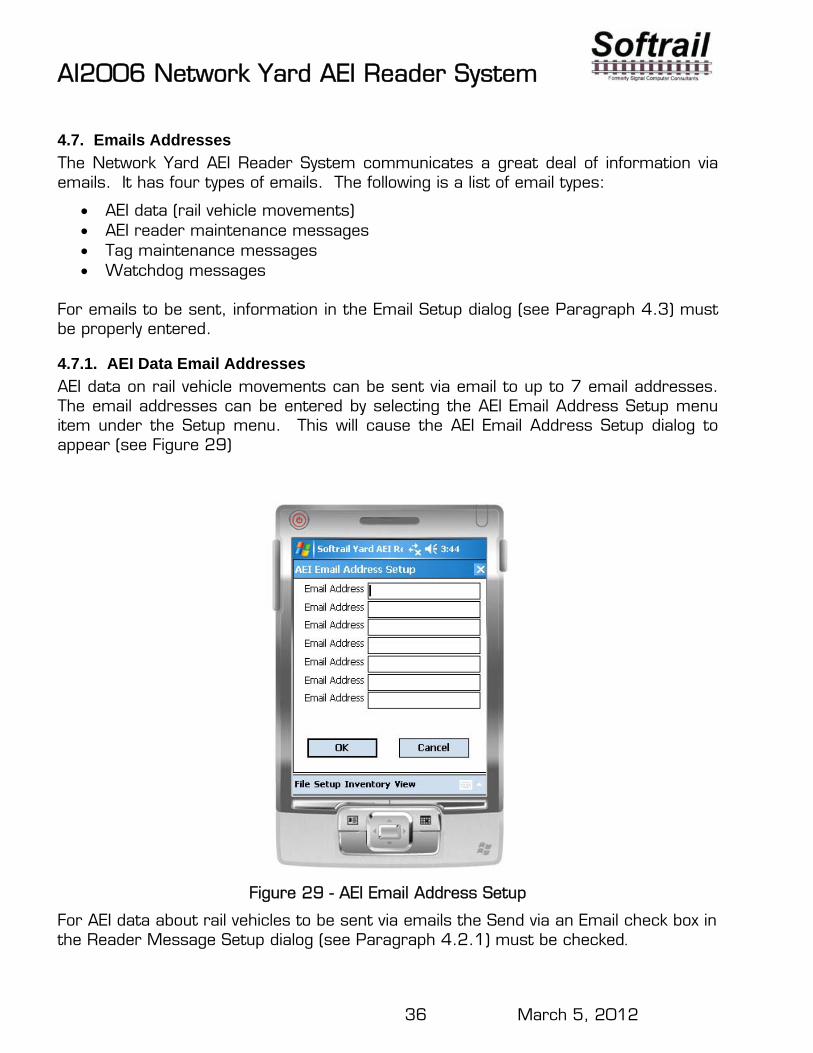
4.7.1. AEI Data Email Addresses
AEI data on rail vehicle movements can be sent via email to up to 7 email addresses. The email addresses can be entered by selecting the AEI Email Address Setup menu item under the Setup menu. This will cause the AEI Email Address Setup dialog to appear (see Figure 29)
Figure 29 - AEI Email Address Setup
For AEI data about rail vehicles to be sent via emails the Send via an Email check box in the Reader Message Setup dialog (see Paragraph 4.2.1) must be checked.
AI2006 Network Yard AEI Reader System
37 March 5, 2012
4.7.2. Maintenance Email Addresses
The Network Yard AEI Reader System is constantly monitoring various components for problems. When it discovers a problem it will automatically send emails about the problem to a list of addresses. The email addresses can be entered by selecting the Maint Email Address Setup menu item under the Setup menu. This will cause the Maintenance Email Address Setup dialog to appear which allows for the entry of up to seven email addresses.
4.7.3. Tag Maintenance Email Addresses
The Network Yard AEI Reader System checks rail vehicles for missing tags and tags that are either mismatched or have incorrect information. When it discovers a tag issue it will automatically send emails to a list of addresses about the tag problem. The email addresses can be entered by selecting the Tag Maint Email Address Setup menu item under the Setup menu. This will cause the Tag Maint Email Address Setup dialog to appear which allows for the entry of up to seven email addresses.
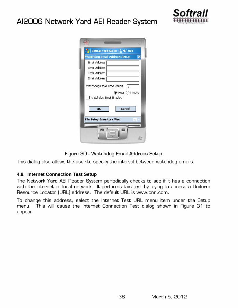
4.7.4. Watchdog Email Addresses
The Network Yard AEI Reader System can periodically send emails to a list of recipients to inform them that the system is up and running. The email addresses can be entered by selecting the Watchdog Email Address Setup menu item under the Setup menu. This will cause the Watchdog Email Address Setup dialog to appear (Figure 30) which allows for the entry of up to four email addresses.
AI2006 Network Yard AEI Reader System
38 March 5, 2012
Figure 30 - Watchdog Email Address Setup
This dialog also allows the user to specify the interval between watchdog emails.
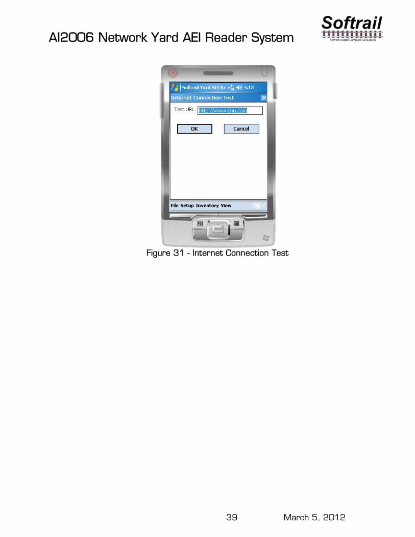
4.8. Internet Connection Test Setup
The Network Yard AEI Reader System periodically checks to see if it has a connection with the internet or local network. It performs this test by trying to access a Uniform Resource Locator (URL) address. The default URL is www.cnn.com.
To change this address, select the Internet Test URL menu item under the Setup menu. This will cause the Internet Connection Test dialog shown in Figure 31 to appear.
AI2006 Network Yard AEI Reader System
39 March 5, 2012
Figure 31 - Internet Connection Test
AI2006 Network Yard AEI Reader System
40 March 5, 2012
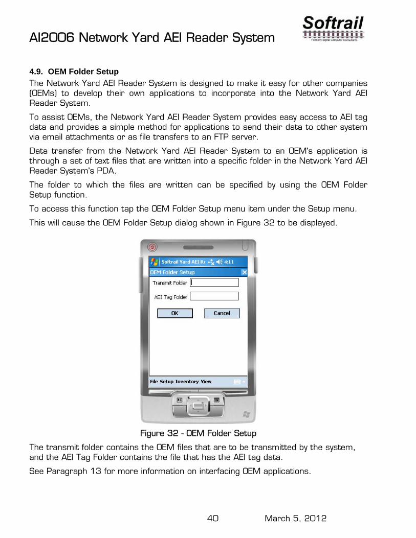
4.9. OEM Folder Setup
The Network Yard AEI Reader System is designed to make it easy for other companies (OEMs) to develop their own applications to incorporate into the Network Yard AEI Reader System.
To assist OEMs, the Network Yard AEI Reader System provides easy access to AEI tag data and provides a simple method for applications to send their data to other system via email attachments or as file transfers to an FTP server.
Data transfer from the Network Yard AEI Reader System to an OEM's application is through a set of text files that are written into a specific folder in the Network Yard AEI Reader System's PDA.
The folder to which the files are written can be specified by using the OEM Folder Setup function.
To access this function tap the OEM Folder Setup menu item under the Setup menu.
This will cause the OEM Folder Setup dialog shown in Figure 32 to be displayed.
Figure 32 - OEM Folder Setup
The transmit folder contains the OEM files that are to be transmitted by the system, and the AEI Tag Folder contains the file that has the AEI tag data.
See Paragraph 13 for more information on interfacing OEM applications.
AI2006 Network Yard AEI Reader System
41 March 5, 2012
5. STATUS DISPLAYS The Network Yard AEI Reader System has three status displays.
The three status displays are the:
System Status Communication Monitor Rail Vehicle Movement Monitor Radar Status (optional)
One of the status displays will be visible on the PDA as long as one of the dialog screens is not open. Tap anywhere on the screen to see the other status screens, and the system will cycle through all three or four (if the radar option is included) status displays.
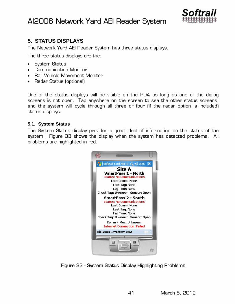
5.1. System Status
The System Status display provides a great deal of information on the status of the system. Figure 33 shows the display when the system has detected problems. All problems are highlighted in red.
Figure 33 - System Status Display Highlighting Problems
AI2006 Network Yard AEI Reader System
42 March 5, 2012
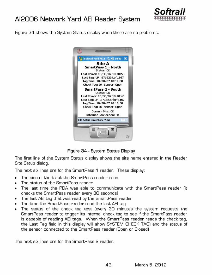
Figure 34 shows the System Status display when there are no problems.
Figure 34 - System Status Display
The first line of the System Status display shows the site name entered in the Reader Site Setup dialog.
The next six lines are for the SmartPass 1 reader. These display:
The side of the track the SmartPass reader is on The status of the SmartPass reader The last time the PDA was able to communicate with the SmartPass reader (it
checks the SmartPass reader every 30 seconds) The last AEI tag that was read by the SmartPass reader The time the SmartPass reader read the last AEI tag The status of the check tag test (every 30 minutes the system requests the
SmartPass reader to trigger its internal check tag to see if the SmartPass reader is capable of reading AEI tags. When the SmartPass reader reads the check tag, the Last Tag field in this display will show SYSTEM CHECK TAG) and the status of the sensor connected to the SmartPass reader (Open or Closed)
The next six lines are for the SmartPass 2 reader.
AI2006 Network Yard AEI Reader System
43 March 5, 2012
The system checks the communication multiplexer to see if it is operating properly. Its status is displayed in the Comm / Mux line.
The system periodically checks to see if it has access to the internet or a local network by trying to access a specific URL. The status of the connection is displayed in the Internet Connection line.
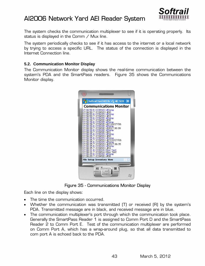
5.2. Communication Monitor Display
The Communication Monitor display shows the real-time communication between the system's PDA and the SmartPass readers. Figure 35 shows the Communications Monitor display.
Figure 35 - Communications Monitor Display
Each line on the display shows:
The time the communication occurred. Whether the communication was transmitted (T) or received (R) by the system's
PDA. Transmitted message are in black, and received message are in blue. The communication multiplexer's port through which the communication took place.
Generally the SmartPass Reader 1 is assigned to Comm Port D and the SmartPass Reader 2 to Comm Port E. Test of the communication multiplexer are performed on Comm Port A, which has a wrap-around plug, so that all data transmitted to com port A is echoed back to the PDA.
AI2006 Network Yard AEI Reader System
44 March 5, 2012
The message that was sent or received. To interpret these messages please refer to the AI1620 System User's Guide Chapter 7 Commands, which can be downloaded by going to http://www.aeitag.com/ai1lowspeeds.html.
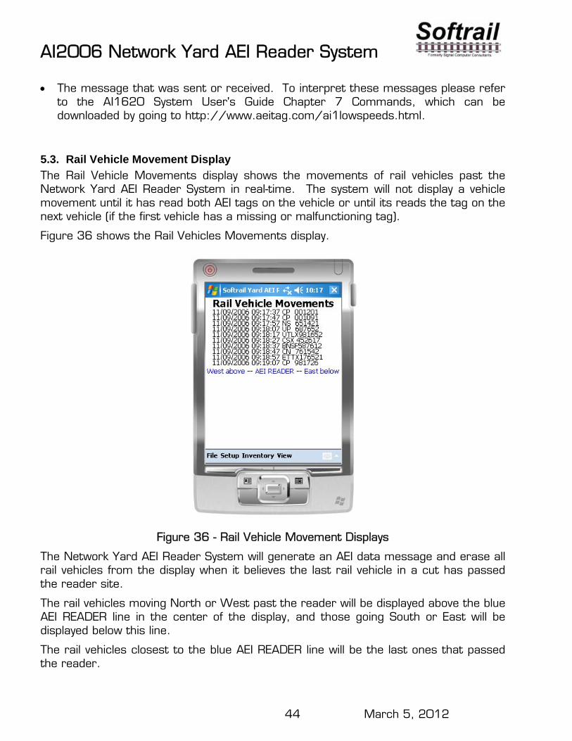
5.3. Rail Vehicle Movement Display
The Rail Vehicle Movements display shows the movements of rail vehicles past the Network Yard AEI Reader System in real-time. The system will not display a vehicle movement until it has read both AEI tags on the vehicle or until its reads the tag on the next vehicle (if the first vehicle has a missing or malfunctioning tag).
Figure 36 shows the Rail Vehicles Movements display.
Figure 36 - Rail Vehicle Movement Displays
The Network Yard AEI Reader System will generate an AEI data message and erase all rail vehicles from the display when it believes the last rail vehicle in a cut has passed the reader site.
The rail vehicles moving North or West past the reader will be displayed above the blue AEI READER line in the center of the display, and those going South or East will be displayed below this line.
The rail vehicles closest to the blue AEI READER line will be the last ones that passed the reader.
AI2006 Network Yard AEI Reader System
45 March 5, 2012
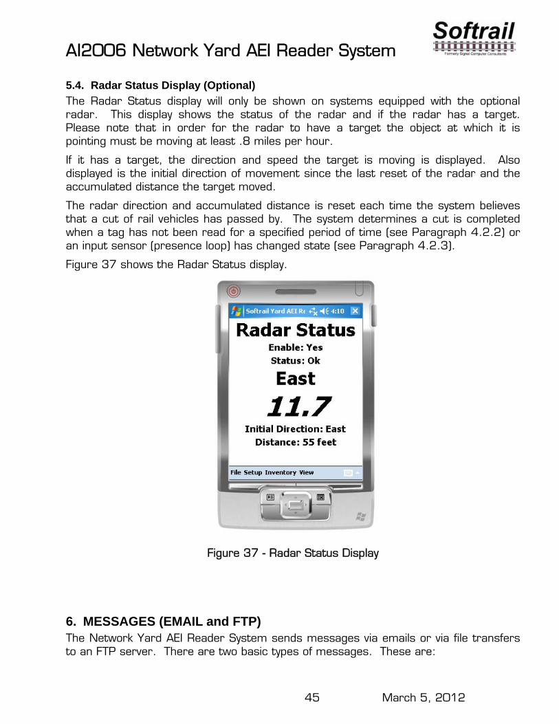
5.4. Radar Status Display (Optional)
The Radar Status display will only be shown on systems equipped with the optional radar. This display shows the status of the radar and if the radar has a target. Please note that in order for the radar to have a target the object at which it is pointing must be moving at least .8 miles per hour.
If it has a target, the direction and speed the target is moving is displayed. Also displayed is the initial direction of movement since the last reset of the radar and the accumulated distance the target moved.
The radar direction and accumulated distance is reset each time the system believes that a cut of rail vehicles has passed by. The system determines a cut is completed when a tag has not been read for a specified period of time (see Paragraph 4.2.2) or an input sensor (presence loop) has changed state (see Paragraph 4.2.3).
Figure 37 shows the Radar Status display.
Figure 37 - Radar Status Display
6. MESSAGES (EMAIL and FTP) The Network Yard AEI Reader System sends messages via emails or via file transfers to an FTP server. There are two basic types of messages. These are:
AI2006 Network Yard AEI Reader System
46 March 5, 2012
AEI data messages with information about rail vehicle movements past the reader Maintenance messages with information about the health of the Network Yard
Reader System or AEI tags on individual rail vehicles.
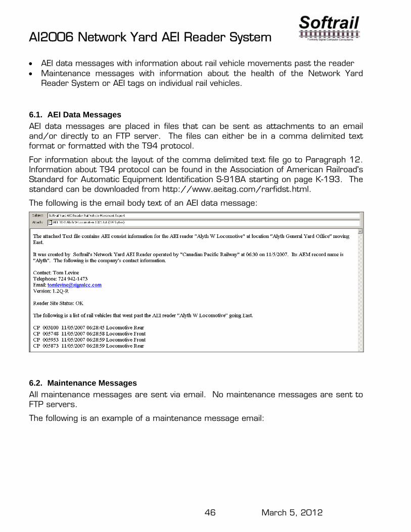
6.1. AEI Data Messages
AEI data messages are placed in files that can be sent as attachments to an email and/or directly to an FTP server. The files can either be in a comma delimited text format or formatted with the T94 protocol.
For information about the layout of the comma delimited text file go to Paragraph 12. Information about T94 protocol can be found in the Association of American Railroad's Standard for Automatic Equipment Identification S-918A starting on page K-193. The standard can be downloaded from http://www.aeitag.com/rarfidst.html.
The following is the email body text of an AEI data message:
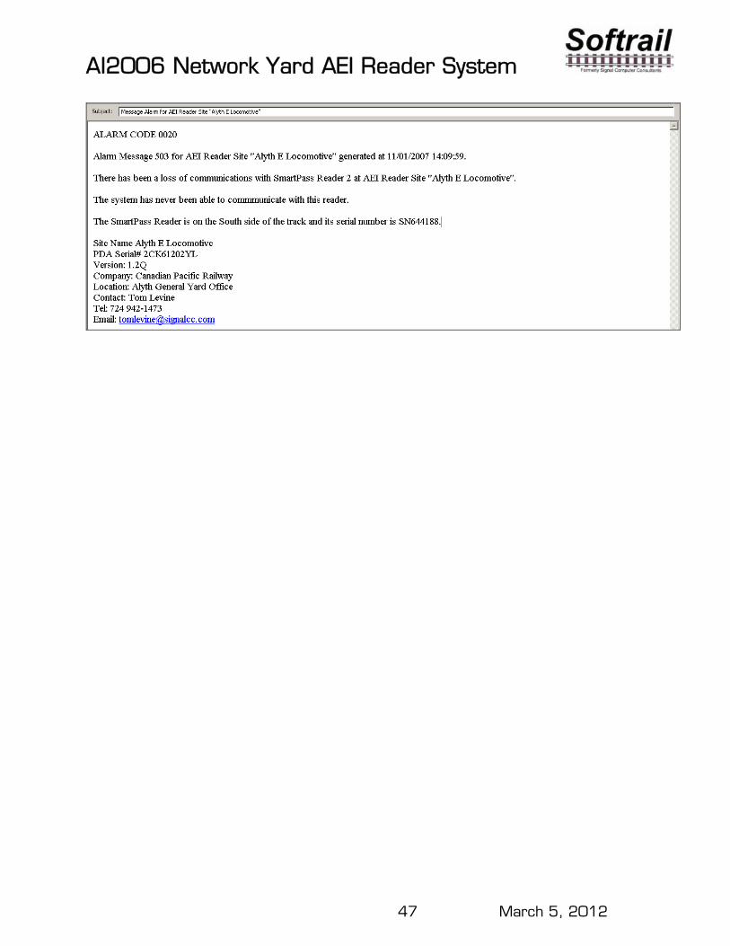
6.2. Maintenance Messages
All maintenance messages are sent via email. No maintenance messages are sent to FTP servers.
The following is an example of a maintenance message email:
AI2006 Network Yard AEI Reader System
47 March 5, 2012

AI2006 Network Yard AEI Reader System
48 March 5, 2012
6.3. Message Status
The status of messages can be viewed by selecting the Message Status menu item under the View menu. This will cause the Message Status dialog shown in Figure 38 to be displayed.
Figure 38 - Message Status
By using the radio buttons near the bottom of the screen, the user can either cause the messages that have been sent or the ones to be sent to be displayed.
7. TIME UPDATE If the AI2006 Network Yard AEI Reader System has access to the internet, the system will periodically update its time the from the National Institute of Standards and Technology' s Internet Time Service at time-a.nist.gov. If the system does not have access to the internet, but is connected to the AEI Rail and Road Manager program, it will get its time from the computer that is hosting the AEI Rail and Road Manager program.
If neither of these services are available, the user must update the PDA's time manually.
AI2006 Network Yard AEI Reader System
49 March 5, 2012
8. MAINTENANCE AND COMMUNICATION LOGS To help find problems with the Network Yard AEI Reader System, the system maintains two log files. These are the maintenance log and the communications log.
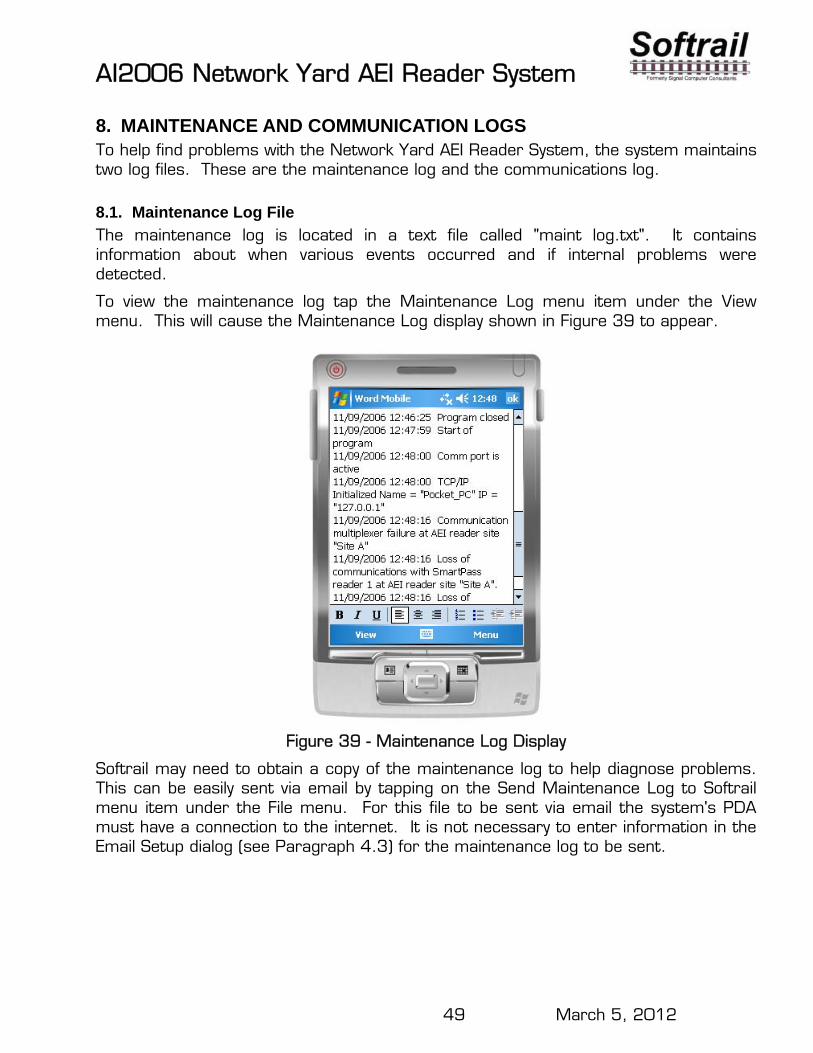
8.1. Maintenance Log File
The maintenance log is located in a text file called "maint log.txt". It contains information about when various events occurred and if internal problems were detected.
To view the maintenance log tap the Maintenance Log menu item under the View menu. This will cause the Maintenance Log display shown in Figure 39 to appear.
Figure 39 - Maintenance Log Display
Softrail may need to obtain a copy of the maintenance log to help diagnose problems. This can be easily sent via email by tapping on the Send Maintenance Log to Softrail menu item under the File menu. For this file to be sent via email the system's PDA must have a connection to the internet. It is not necessary to enter information in the Email Setup dialog (see Paragraph 4.3) for the maintenance log to be sent.
AI2006 Network Yard AEI Reader System
50 March 5, 2012
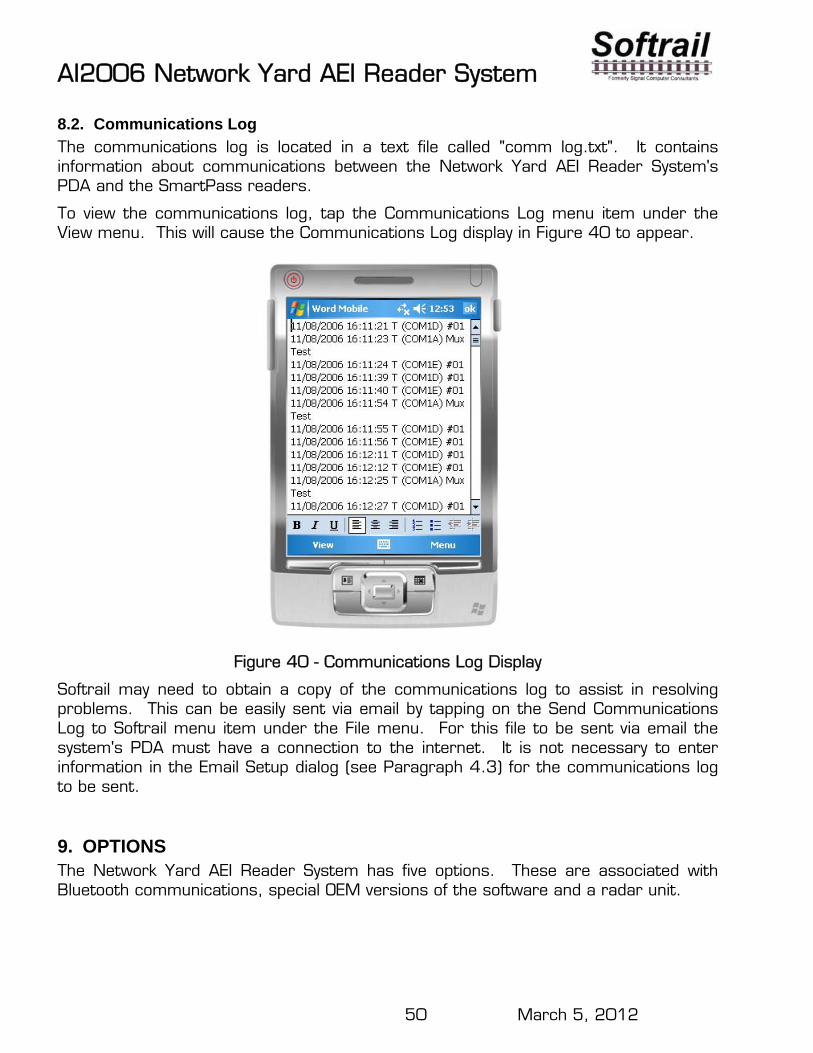
8.2. Communications Log
The communications log is located in a text file called "comm log.txt". It contains information about communications between the Network Yard AEI Reader System's PDA and the SmartPass readers.
To view the communications log, tap the Communications Log menu item under the View menu. This will cause the Communications Log display in Figure 40 to appear.
Figure 40 - Communications Log Display
Softrail may need to obtain a copy of the communications log to assist in resolving problems. This can be easily sent via email by tapping on the Send Communications Log to Softrail menu item under the File menu. For this file to be sent via email the system's PDA must have a connection to the internet. It is not necessary to enter information in the Email Setup dialog (see Paragraph 4.3) for the communications log to be sent.
9. OPTIONS The Network Yard AEI Reader System has five options. These are associated with Bluetooth communications, special OEM versions of the software and a radar unit.
AI2006 Network Yard AEI Reader System
51 March 5, 2012
The Bluetooth Device Connections option allows external devices (sensors, scales, etc) to communicate with the system's PDA, marries the devices' data with the AEI data, and reports the information together.
The Bluetooth Telephone Connection allows the system's PDA to connect to the internet using a Bluetooth enabled telephone.
The OEM version of the system allows other companies to develop their own applications. These applications can be easily incorporated into the system's PDA. The OEM version provides an easy interface so that AEI tag data can be accessed by an OEM's application and sent to other systems via an email or a file transfer to an FTP server (see Paragraph 13).
A radar unit can be interfaced to the system. The radar unit is used to determine the direction of movement past the reader system and to detect untagged rail vehicles when used in conjunction with a presence loop.
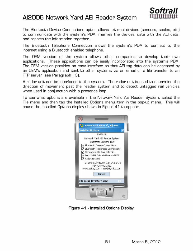
To see what options are available in the Network Yard AEI Reader System, select the File menu and then tap the Installed Options menu item in the pop-up menu. This will cause the Installed Options display shown in Figure 41 to appear.
Figure 41 - Installed Options Display
AI2006 Network Yard AEI Reader System
52 March 5, 2012
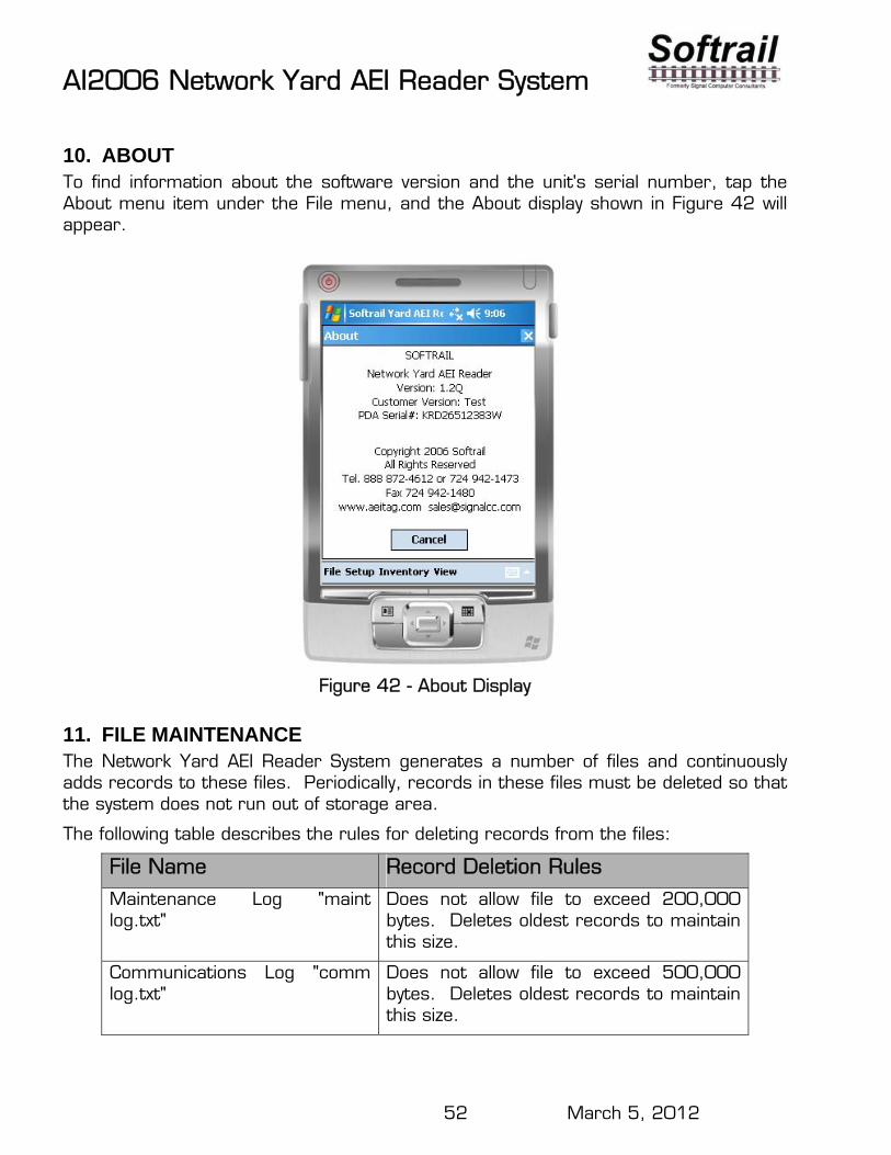
10. ABOUT To find information about the software version and the unit's serial number, tap the About menu item under the File menu, and the About display shown in Figure 42 will appear.
Figure 42 - About Display
11. FILE MAINTENANCE The Network Yard AEI Reader System generates a number of files and continuously adds records to these files. Periodically, records in these files must be deleted so that the system does not run out of storage area.
The following table describes the rules for deleting records from the files:
File Name Record Deletion Rules
Maintenance Log "maint log.txt"
Does not allow file to exceed 200,000 bytes. Deletes oldest records to maintain this size.
Communications Log "comm log.txt"
Does not allow file to exceed 500,000 bytes. Deletes oldest records to maintain this size.
AI2006 Network Yard AEI Reader System
53 March 5, 2012
OEM Tag Data "tag data.txt" Does not allow file to exceed 20,000 bytes. Deletes oldest records to maintain this size.
OEM Status Log "oem status.txt"
Does not allow file to exceed 20,000 bytes. Deletes oldest records to maintain this size.
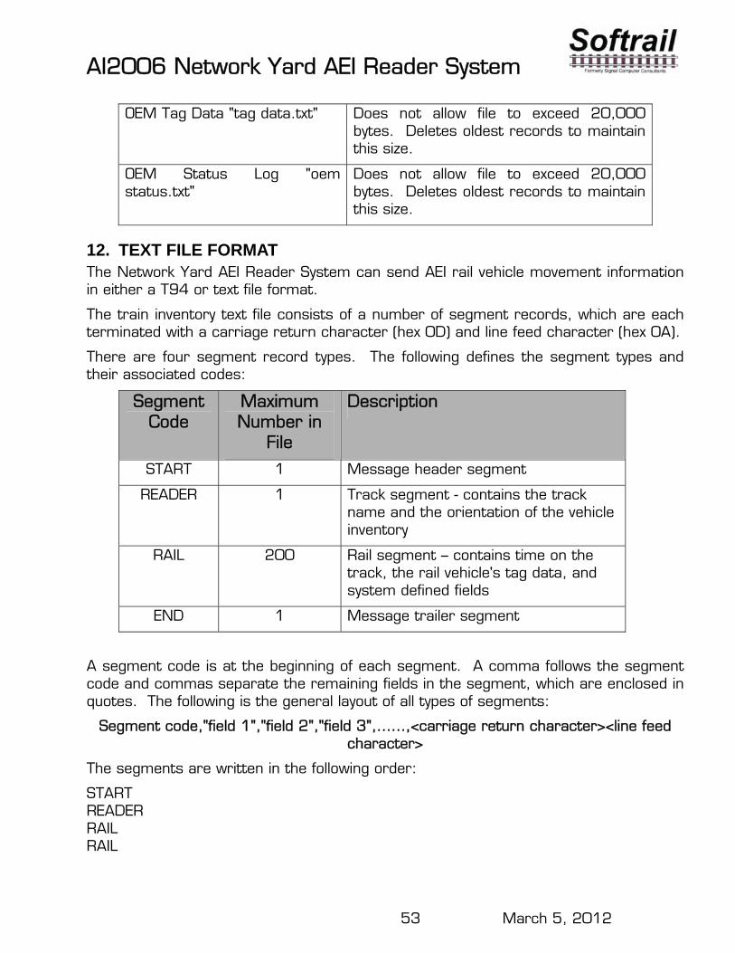
12. TEXT FILE FORMAT The Network Yard AEI Reader System can send AEI rail vehicle movement information in either a T94 or text file format.
The train inventory text file consists of a number of segment records, which are each terminated with a carriage return character (hex 0D) and line feed character (hex 0A).
There are four segment record types. The following defines the segment types and their associated codes:
Segment Code
Maximum Number in
File
Description
START 1 Message header segment
READER 1 Track segment - contains the track name and the orientation of the vehicle inventory
RAIL 200 Rail segment – contains time on the track, the rail vehicle's tag data, and system defined fields
END 1 Message trailer segment
A segment code is at the beginning of each segment. A comma follows the segment code and commas separate the remaining fields in the segment, which are enclosed in quotes. The following is the general layout of all types of segments:
Segment code,"field 1","field 2","field 3",……,<carriage return character><line feed character>
The segments are written in the following order:
START READER RAIL RAIL

AI2006 Network Yard AEI Reader System
54 March 5, 2012
RAIL RAIL RAIL RAIL . . END
AI2006 Network Yard AEI Reader System
55 March 5, 2012
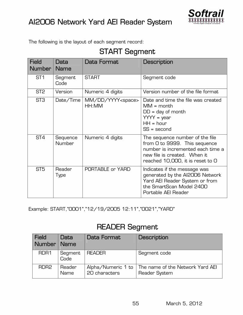
The following is the layout of each segment record:
START Segment Field Number
Data Name
Data Format Description
ST1 Segment Code
START Segment code
ST2 Version Numeric 4 digits Version number of the file format
ST3 Date/Time MM/DD/YYYY<space> HH:MM
Date and time the file was created MM = month DD = day of month YYYY = year HH = hour SS = second
ST4 Sequence Number
Numeric 4 digits The sequence number of the file from 0 to 9999. This sequence number is incremented each time a new file is created. When it reached 10,000, it is reset to 0
ST5 Reader Type
PORTABLE or YARD Indicates if the message was generated by the AI2006 Network Yard AEI Reader System or from the SmartScan Model 2400 Portable AEI Reader
Example: START,"0001","12/19/2005 12:11","0021","YARD"
READER Segment Field Number
Data Name
Data Format Description
RDR1 Segment Code
READER Segment code
RDR2 Reader Name
Alpha/Numeric 1 to 20 characters
The name of the Network Yard AEI Reader System
AI2006 Network Yard AEI Reader System
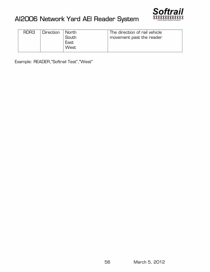
56 March 5, 2012
RDR3 Direction North South East West
The direction of rail vehicle movement past the reader
Example: READER,"Softrail Test","West"
AI2006 Network Yard AEI Reader System
57 March 5, 2012
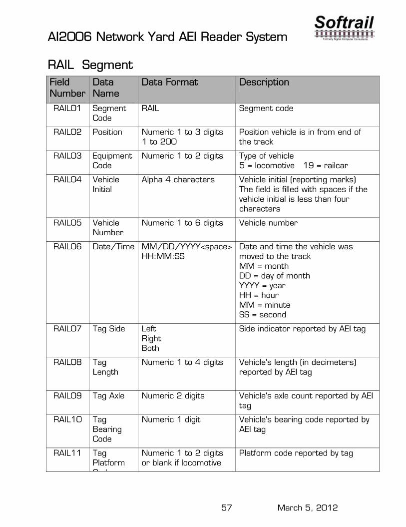
RAIL Segment Field Number
Data Name
Data Format Description
RAIL01 Segment Code
RAIL Segment code
RAIL02 Position
Numeric 1 to 3 digits 1 to 200
Position vehicle is in from end of the track
RAIL03 Equipment Code
Numeric 1 to 2 digits Type of vehicle 5 = locomotive 19 = railcar
RAIL04 Vehicle Initial
Alpha 4 characters Vehicle initial (reporting marks) The field is filled with spaces if the vehicle initial is less than four characters
RAIL05 Vehicle Number
Numeric 1 to 6 digits Vehicle number
RAIL06 Date/Time
MM/DD/YYYY<space> HH:MM:SS
Date and time the vehicle was moved to the track MM = month DD = day of month YYYY = year HH = hour MM = minute SS = second
RAIL07 Tag Side
Left Right Both
Side indicator reported by AEI tag
RAIL08 Tag Length
Numeric 1 to 4 digits Vehicle's length (in decimeters) reported by AEI tag
RAIL09 Tag Axle Numeric 2 digits Vehicle's axle count reported by AEI tag
RAIL10 Tag Bearing Code
Numeric 1 digit
Vehicle's bearing code reported by AEI tag
RAIL11 Tag Platform Code
Numeric 1 to 2 digits or blank if locomotive
Platform code reported by tag
AI2006 Network Yard AEI Reader System
58 March 5, 2012
Code
Example: RAIL,"1","5","NS ","1526","01/17/2006 10:41:54","Left","183","4","1"
AI2006 Network Yard AEI Reader System
59 March 5, 2012
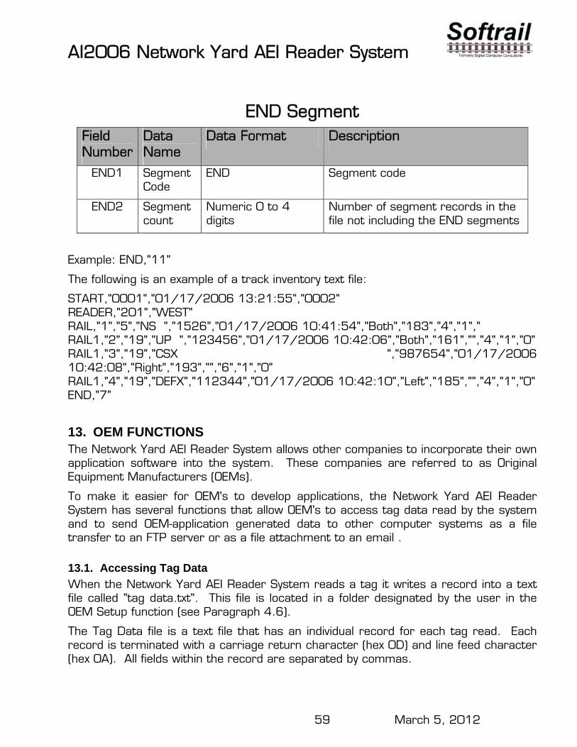
END Segment Field Number
Data Name
Data Format Description
END1 Segment Code
END Segment code
END2 Segment count
Numeric 0 to 4 digits
Number of segment records in the file not including the END segments
Example: END,"11"
The following is an example of a track inventory text file:
START,"0001","01/17/2006 13:21:55","0002" READER,"201","WEST" RAIL,"1","5","NS ","1526","01/17/2006 10:41:54","Both","183","4","1"," RAIL1,"2","19","UP ","123456","01/17/2006 10:42:06","Both","161","","4","1","0" RAIL1,"3","19","CSX ","987654","01/17/2006 10:42:08","Right","193","","6","1","0" RAIL1,"4","19","DEFX","112344","01/17/2006 10:42:10","Left","185","","4","1","0" END,"7"
13. OEM FUNCTIONS The Network Yard AEI Reader System allows other companies to incorporate their own application software into the system. These companies are referred to as Original Equipment Manufacturers (OEMs).
To make it easier for OEM's to develop applications, the Network Yard AEI Reader System has several functions that allow OEM's to access tag data read by the system and to send OEM-application generated data to other computer systems as a file transfer to an FTP server or as a file attachment to an email .
13.1. Accessing Tag Data
When the Network Yard AEI Reader System reads a tag it writes a record into a text file called "tag data.txt". This file is located in a folder designated by the user in the OEM Setup function (see Paragraph 4.6).
The Tag Data file is a text file that has an individual record for each tag read. Each record is terminated with a carriage return character (hex 0D) and line feed character (hex 0A). All fields within the record are separated by commas.
AI2006 Network Yard AEI Reader System
60 March 5, 2012
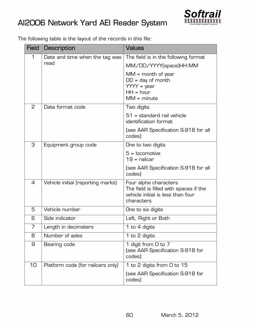
The following table is the layout of the records in this file:
Field Description Values
1 Date and time when the tag was read
The field is in the following format
MM/DD/YYYY(space)HH:MM
MM = month of year DD = day of month YYYY = year HH = hour MM = minute
2 Data format code Two digits
51 = standard rail vehicle identification format
(see AAR Specification S-918 for all codes)
3 Equipment group code One to two digits
5 = locomotive 19 = railcar
(see AAR Specification S-918 for all codes)
4 Vehicle initial (reporting marks) Four alpha characters The field is filled with spaces if the vehicle initial is less than four characters
5 Vehicle number One to six digits
6 Side indicator Left, Right or Both
7 Length in decimeters 1 to 4 digits
8 Number of axles 1 to 2 digits
9 Bearing code 1 digit from 0 to 7 (see AAR Specification S-918 for codes)
10 Platform code (for railcars only) 1 to 2 digits from 0 to 15
(see AAR Specification S-918 for codes)
AI2006 Network Yard AEI Reader System
61 March 5, 2012
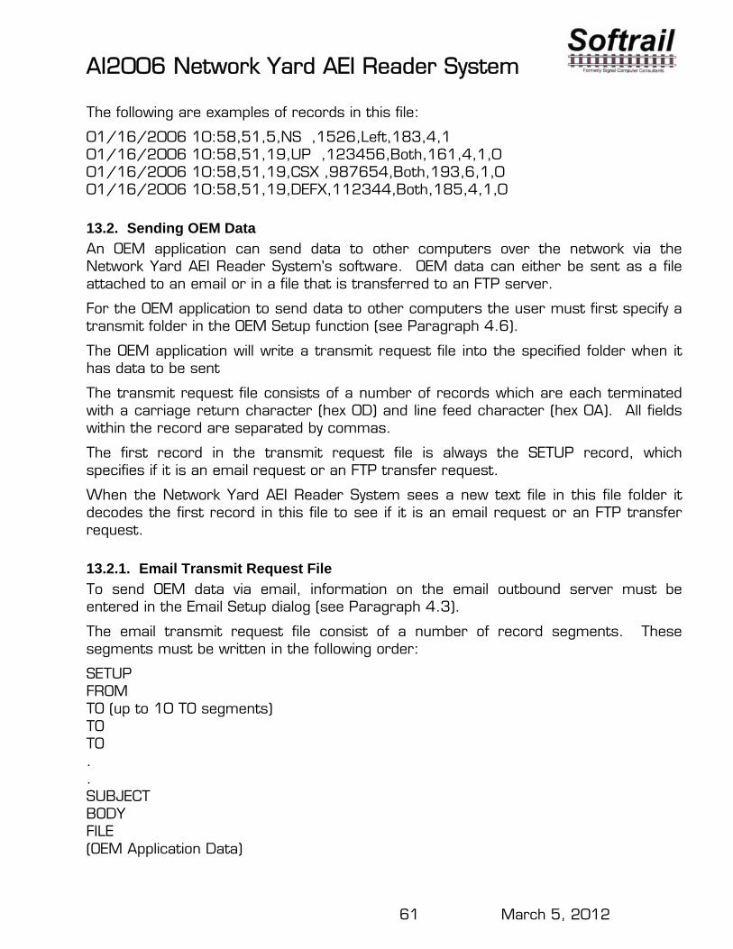
The following are examples of records in this file:
01/16/2006 10:58,51,5,NS ,1526,Left,183,4,1 01/16/2006 10:58,51,19,UP ,123456,Both,161,4,1,0 01/16/2006 10:58,51,19,CSX ,987654,Both,193,6,1,0 01/16/2006 10:58,51,19,DEFX,112344,Both,185,4,1,0
13.2. Sending OEM Data
An OEM application can send data to other computers over the network via the Network Yard AEI Reader System's software. OEM data can either be sent as a file attached to an email or in a file that is transferred to an FTP server.
For the OEM application to send data to other computers the user must first specify a transmit folder in the OEM Setup function (see Paragraph 4.6).
The OEM application will write a transmit request file into the specified folder when it has data to be sent
The transmit request file consists of a number of records which are each terminated with a carriage return character (hex 0D) and line feed character (hex 0A). All fields within the record are separated by commas.
The first record in the transmit request file is always the SETUP record, which specifies if it is an email request or an FTP transfer request.
When the Network Yard AEI Reader System sees a new text file in this file folder it decodes the first record in this file to see if it is an email request or an FTP transfer request.
13.2.1. Email Transmit Request File
To send OEM data via email, information on the email outbound server must be entered in the Email Setup dialog (see Paragraph 4.3).
The email transmit request file consist of a number of record segments. These segments must be written in the following order:
SETUP FROM TO (up to 10 TO segments) TO TO . . SUBJECT BODY FILE (OEM Application Data)
AI2006 Network Yard AEI Reader System
62 March 5, 2012
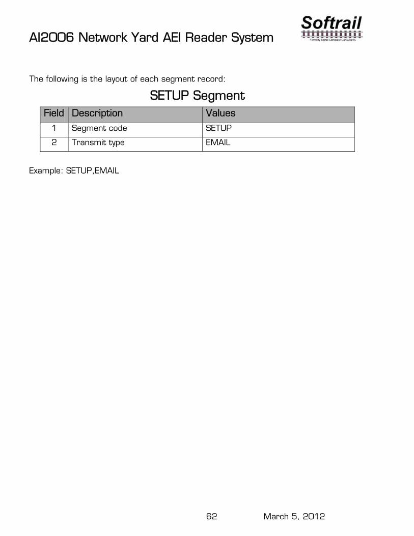
The following is the layout of each segment record:
SETUP Segment Field Description Values
1 Segment code SETUP
2 Transmit type EMAIL
Example: SETUP,EMAIL
AI2006 Network Yard AEI Reader System
63 March 5, 2012
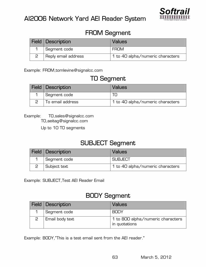
FROM Segment Field Description Values
1 Segment code FROM
2 Reply email address 1 to 40 alpha/numeric characters
Example: FROM,[email protected]
TO Segment Field Description Values
1 Segment code TO
2 To email address 1 to 40 alpha/numeric characters
Example: TO,[email protected] TO,[email protected]
Up to 10 TO segments
SUBJECT Segment Field Description Values
1 Segment code SUBJECT
2 Subject text 1 to 40 alpha/numeric characters
Example: SUBJECT,Test AEI Reader Email
BODY Segment Field Description Values
1 Segment code BODY
2 Email body text 1 to 800 alpha/numeric characters in quotations
Example: BODY,"This is a test email sent from the AEI reader."
AI2006 Network Yard AEI Reader System
64 March 5, 2012
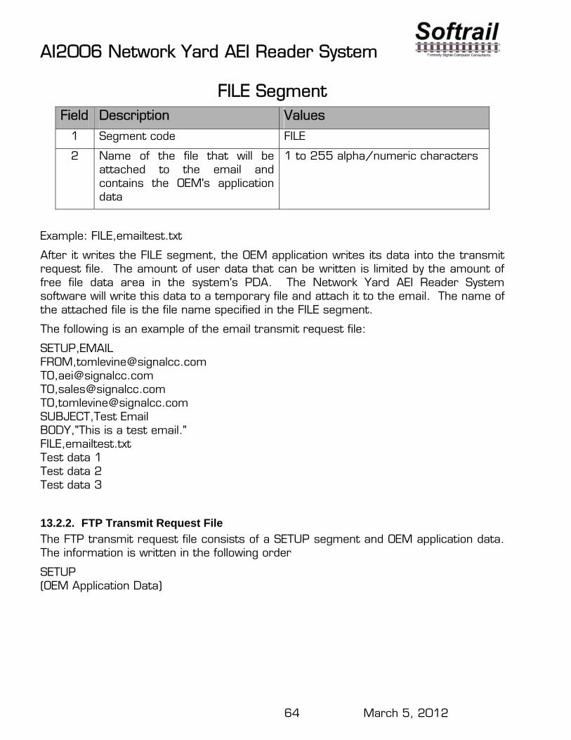
FILE Segment Field Description Values
1 Segment code FILE
2 Name of the file that will be attached to the email and contains the OEM's application data
1 to 255 alpha/numeric characters
Example: FILE,emailtest.txt
After it writes the FILE segment, the OEM application writes its data into the transmit request file. The amount of user data that can be written is limited by the amount of free file data area in the system's PDA. The Network Yard AEI Reader System software will write this data to a temporary file and attach it to the email. The name of the attached file is the file name specified in the FILE segment.
The following is an example of the email transmit request file:
SETUP,EMAIL FROM,[email protected] TO,[email protected] TO,[email protected] TO,[email protected] SUBJECT,Test Email BODY,"This is a test email." FILE,emailtest.txt Test data 1 Test data 2 Test data 3
13.2.2. FTP Transmit Request File
The FTP transmit request file consists of a SETUP segment and OEM application data. The information is written in the following order
SETUP (OEM Application Data)
AI2006 Network Yard AEI Reader System
65 March 5, 2012
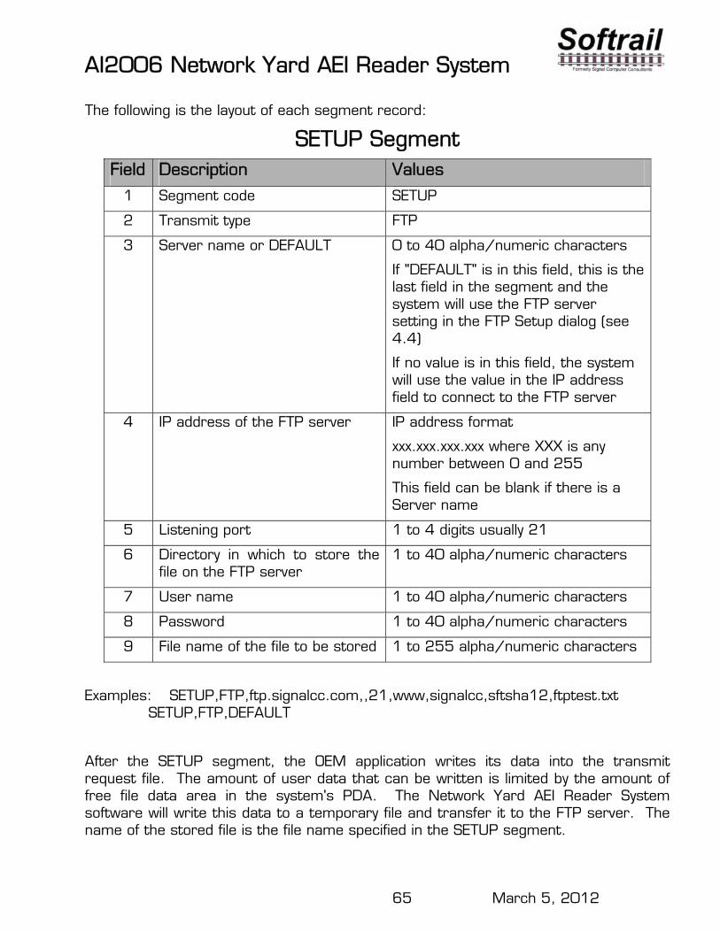
The following is the layout of each segment record:
SETUP Segment Field Description Values
1 Segment code SETUP
2 Transmit type FTP
3 Server name or DEFAULT 0 to 40 alpha/numeric characters
If "DEFAULT" is in this field, this is the last field in the segment and the system will use the FTP server setting in the FTP Setup dialog (see 4.4)
If no value is in this field, the system will use the value in the IP address field to connect to the FTP server
4 IP address of the FTP server IP address format
xxx.xxx.xxx.xxx where XXX is any number between 0 and 255
This field can be blank if there is a Server name
5 Listening port 1 to 4 digits usually 21
6 Directory in which to store the file on the FTP server
1 to 40 alpha/numeric characters
7 User name 1 to 40 alpha/numeric characters
8 Password 1 to 40 alpha/numeric characters
9 File name of the file to be stored 1 to 255 alpha/numeric characters
Examples: SETUP,FTP,ftp.signalcc.com,,21,www,signalcc,sftsha12,ftptest.txt SETUP,FTP,DEFAULT
After the SETUP segment, the OEM application writes its data into the transmit request file. The amount of user data that can be written is limited by the amount of free file data area in the system's PDA. The Network Yard AEI Reader System software will write this data to a temporary file and transfer it to the FTP server. The name of the stored file is the file name specified in the SETUP segment.
AI2006 Network Yard AEI Reader System
66 March 5, 2012
The following is an example of the FTP transmit request file:
SETUP,FTP,ftp.signalcc.com,192.168.0.1,21,www,signalcc,7yg2512aa,ftptest.txt Test data 1 Test data 2 Test data 3
13.2.3. OEM Transmit Request Status
When the Network Yard AEI Reader System reads an OEM transmit request file, it will check the file for errors. If it finds an error it writes an error record into a file called "oem status log.txt", which is located in the same folder as the transmit request files. The following is the format of an error record: Error,"transmit request file name","error description". The following are examples of error records: Error,"testftp.txt","no FTP file name in the first record of the OEM FTP transmit file" Error,"testftp.txt","missing password in the first record of the OEM FTP transmit file" Error,"testemail"," could not find carriage return or line feed at the end of "FROM" record in the OEM Email transmit file" A record will be written in the "oem status log.txt" file when the data in a transmit request file is successfully sent. The following are the email and FTP formats for a sent status record: SENT,mm/dd/yyyy hh:mm, EMAIL, "transmit request file name" SENT,mm/dd/yyyy hh:mm, FTP, "transmit request file name"

AI2006 Network Yard AEI Reader System
67 March 5, 2012
14. TECHNICAL SUPPORT AND UPDATES Periodically Softrail issues maintenance releases and new versions of this program. Maintenance releases are free and correct problems found with the program and/or provide minor enhancements to the program. Before contacting us with problems we suggest that you check our web page at www.aeitag.com to insure that you have the latest maintenance release of the program.
Technical support is free for the first one year after purchase. A maintenance agreement can be purchased to extend the period of technical support.
For technical support or more information on the maintenance agreement contact Softrail at:
Softrail, Inc. 1098 Venetia Road Eighty Four, PA 15330 Tel. 888 872-4612 (toll free US and Canada only) or 724 942-1473 Fax. 724 942-1480 E-mail [email protected] Web Page www.aeitag.com

AI2006 Network Yard AEI Reader System
1 March 5, 2012
Index AEI data message, 46 AEI Rail & Road Manager, 33 Bluetooth options, 50 check tag, 42 Communication Monitor display, 13, 43 communication multiplexer, 4, 10 communications log, 50 configuration, 21 contact information, 23 controller, 4 deliverables, 3 Doppler radar, 16 email
address list, 36 messages, 45 OEM, 61 setup, 31
file maintenance, 52 FTP, 45
server setup, 32 installation, 3 internet, 15, 38 LAN connection, 15 maintenance log, 49 maintenance messages, 46 message
AEI data, 46 maintenance, 46 status, 48
multiplexer, 4 OEM
accessing tag data, 59 folder setup, 40 functions, 59 options, 50 sending data, 61 sending email, 61 sending FTP, 64 sending status, 66
options Bluetooth, 50 OEM, 50
radar, 50 overview, 1 PDA, 4
IP address, 34 name, 34 serial number, 52
presence loop, 27 Presence Radar, 16 QT50R, 16 radar, 34
Doppler, 16 presence, 16
Radar Status display, 45 Rail Vehicle Movement display, 14, 44 reader
message setup, 25 orientation, 26 site parameters, 24
reset, 12 sensors, 27 serial number, 52 setup
AEI Rail & Road Manager, 33 email, 31 FTP server, 32 OEM folder setup, 40 radar, 34 TCP/IP, 33
SmartPass installation, 3 parameters, 30 serial number, 30
switch monitor, 27 System Status display, 12, 41 tag filtering, 27 TCP/IP
setup, 33 technical support, 67 terminal assignments, 7 text file format, 53 time update, 48 version, 52