Embed Size (px)
Citation preview

AIAA 2000-2234
Flow Control Opportunities inGas Turbine Engines
W. K. LordPratt & WhitneyEast Hartford, CT
D. G. MacMartin and T. G. TillmanUnited Technologies Research CenterEast Hartford CT
Fluids 200019-22 June 2000 / Denver, CO

AIAA 2000-2234
1American Institute of Aeronautics and Astronautics
FLOW CONTROL OPPORTUNITIES IN GAS TURBINE ENGINES
Wesley K. Lord* Douglas G. MacMartin† Gregory Tillman**
Pratt & Whitney United Technologies Research Center East Hartford, CT East Hartford, CT
* Development Engineer, Senior Member, AIAA.† Principal Research Engineer, Senior Member AIAA** Senior Research Engineer. Senior Member AIAA.
Copyright 2000 by United Technologies Corporation.Published by the American Institute of Aeronautics and Astronautics, Inc., with permission.
ABSTRACTRecent advances in flow control have the potential forsignificant impact on the design and performance ofmodern gas-turbine engines. Flow control has thepotential to delay separation, enhance mixing of fluids,create “virtual” shapes, modify wake behavior, andreduce drag. Various opportunities for flow controlthroughout the engine are discussed in terms of theirimpact on the compressor, combustor, turbine, and inletand nozzle. The impact that many of these could haveis substantial; this is discussed in the context of keyengine metrics, and the issues that must be overcome torealize this vision.
INTRODUCTION
Modern gas-turbine engines are complex systems thatconvert chemical potential energy into useful flowenergy safely, reliably, and efficiently, with minimumlife cycle cost and weight. As such, they move largequantities of air, and their ability to deliver depends onour ability to control that flow. The emerging field offlow control thus has the potential for significant impacton gas turbine engines, with opportunities throughoutthe engine to impact key product metrics.
The definition of flow control that we adopt here is theuse of a small modification (e.g. fluid injection) tochange the behavior of a much larger flow. Thisdefinition is intentionally sufficiently broad as to notpreclude purely passive geometry modifications such asriblets or vortex generators, although the primary intentis to consider the impact of recent and futuretechnology innovations. The key emphasis is on theability to modify the behavior of the larger flow withouthaving to act on the scale of that flow. The concept offlow control is not new, with boundary layer blowing orsuction to delay separation known since Prandtl1, and inuse today in areas such as supersonic inlets. Morerecent results provide the promise of achieving similarbenefits with much lower actuation levels. One of themore mature such technologies, for example, applies
unsteady forcing of the boundary layer to enableseparation control at much lower authority requirementsby coupling into dynamics of the flow2,3. In addition tomitigating separation, flow control has the potential toenhance or modify mixing4, create a controllable“virtual” shape5, manage wakes6,7, control boundarylayer drag8,9, etc.; an excellent review of flow control isgiven by Gad-el-Hak10. The purpose of this paper isnot to describe the technology, but the applications offlow control to the gas-turbine engine, and the impactthese might have on the system. The organization ofthis paper is first to briefly discuss the key metrics forthe engine, then to describe possible opportunities foreach component area, and finally to discuss some keyissues and challenges that must be overcome.
The basic components of the propulsion system are thefan and compressor, the combustor, turbine, inlet andnacelle, and nozzle. A detailed description of enginecomponents and design can be found in any of severaltextbooks. Typical P&W (tactical) military andcommercial (or more generally subsonic transport)engines are shown in Figures 1 and 2. The commercialengine is shown integrated with the nacelle in Figure 4;the nacelle is an integral part of the propulsion systemand has several significant opportunities for flowcontrol.
There are several key differences between the militaryand commercial engines, most obviously the bypassratio; the commercial engine generates most of its thrustfrom the large, low pressure ratio fan, and thus also hasa much larger turbine to take more energy out of thecore flow. The military engine shown here includes alarge augmentor for short duration high thrust, and avectoring nozzle. The difference between these twoillustrates the difference between optimizing primarilyfor thrust-specific fuel consumption (TSFC), versusoptimizing thrust/weight. Any discussion of the metricsmust include an understanding of the difference inpriorities for the different customers.

2American Institute of Aeronautics and Astronautics
Figure 1. F119-PW-100 engine (used in F-22 Advanced Tactical Fighter). 3-stage fan,6-stage compressor, single stage LPT and HPT, thrust vectoring nozzle.
Figure 2. PW 4084 engine (used in 777 aircraft). Fan, 6-stage LPC, 11-stage HPC,2-stage HPT, 7-stage LPT.
Hull Insurance 2.9%
Commercial Transport DOC
Crew21.5%
Maintenance20.5%
POL33.6%
Depreciation21.2%
Military Fighter LCC
POL 3.3%
OperationAnd
Support20.6%
Maintenance20.5%
Procurement44.4%
RDT&E11.2%
Figure 3. Comparison oftypical commercial directoperating cost (DOC) andmilitary fighter life cycle cost(LCC) breakdown. POL(petroleum, oil and lubricant)is primarily fuel, RDT&E isdevelopment cost.
Fan nozzle
Primarynozzle
Figure 4. PW 4168 (100" fan) showing the nacelle for aseparate flow configuration.
ENGINE CUSTOMER METRICSThe ultimate metric, of course, is providing maximumvalue to the engine customer, at minimum cost. Thereare a number of factors that are relevant:
• Thrust specific fuel consumption (TSFC)• Weight• Manufacturing cost• Maintenance cost
• Reliability• Noise• Emissions• Low-observability (IR and radar cross-section)• Propulsion airframe integration (PAI)
Trade factors can be established between differentmetrics, these depend on the engine / airframecombination, mission (e.g. short vs. long range), priceof fuel, and so forth. Defining a single number astypical is therefore not possible; for weight, forexample, it can range from less than $500 of initialengine cost per pound to as high as $3000.
A primary contributor to operating or life-cycle cost isfuel consumption, but initial acquisition andmaintenance costs are also significant. Thus one cannotadd limitless cost or complexity to an engine in arelentless drive to reduce TSFC. Previous work onriblets was not adopted for commercial aircraft due tothe maintenance cost11, a similar situation exists forlaminar flow control (also discussed in Ref. 11); thecost of fuel would have to increase for these
3American Institute of Aeronautics and Astronautics
technologies to be considered. Because the utilizationof a military engine is much lower than for acommercial engine, the fuel consumption is much lesscritical than other factors, as shown in Figure 3.Weight is an issue for both military and commercialengines. Note that an extra pound of engine weightrequires extra wing area for added lift, extra fuel, andthus ultimately translates into much more than theoriginal pound in extra total system weight.
Noise and emissions are increasingly becomingimportant differentiators in the commercial enginebusiness, driven by regulations. Many airports restrictaccess based on noise. Furthermore, for short-hopflights, noise-abatement flight profiles can addsignificant time to the total flight, and thus a noisereduction can translate directly into value for theairline. Emissions have been a concern for many yearsbecause of local air quality, primarily from NOX, CO,smoke, and unburned hydrocarbons. Total NOxemissions are subject to regulations that are becomingincreasingly stringent, and several European countries(Sweden and Switzerland) have started imposinglanding penalties based on NOX emissions. A morerecent concern is the impact of emissions on globalclimate change (GCC)12. The primary impact on GCCfrom aircraft engine emissions comes from CO2, whichis a major greenhouse gas, although the impact of otheremissions such as NOx can also be significant. Short ofchanging fuel, only improvements in fuel efficiency canimpact CO2 production.
Propulsion / airframe integration (PAI) is relevant toboth military and commercial customers, although theissues differ. For commercial engines, nacelle diameterand length are important. Military engines also facelow-observability (LO) requirements, both IR and radarcross-section, along with PAI issues with integratingvectoring and afterburning engines into LO-constrainedaircraft designs. The engine must also operate reliablyover its flight envelope, thus requiring potentialcompromises between take-off and cruise. Finally, andperhaps most important of all, is that both military andcommercial customers are paying for (predictable)availability. An aircraft on the ground is not generatingrevenue or conducting missions, and particularly in thecase of unscheduled maintenance, this can dramaticallyalter the cost equation. Key reliability metrics includenon-recoverable in-flight shut-downs, unscheduledengine removals, and extended twin operations(ETOPS) capability.
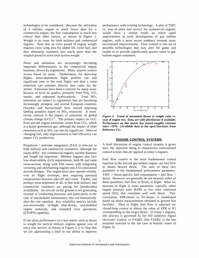
If one plots performance on a key metric such as thrustto weight for tactical military engines against year ofentry into service, as shown in Figure 5, it is clear thatwe are approaching a limit in our ability to improve
performance with existing technology. A plot of TSFCvs. year of entry into service for commercial engineswould show a similar trend; an initial rapidimprovement in early development of gas turbineengines, with a more recent tendency towards moreincremental improvements. Flow control is one set ofpossible technologies that may alter the game andenable us to provide significantly greater value to gasturbine engine customers.
55 60 65 70 75 80 85 90 954
4.5
5
5.5
6
6.5
7
7.5
8
Year of Engine Test
Thr
ust
to W
eigh
t R
atio
(w
ith A
fter
burn
er)
Figure 5. Trend of maximum thrust to weight ratio vs.year of engine test. Data are with afterburner if available.Performance on this metric has stayed roughly constantsince ~1970. (Available data in the open literature fromReference 13.)
ENGINE CONTROL SYSTEMSA brief discussion of engine control systems is givenhere, the objective being to characterize conventionalcontrol actions that are applied in today’s engines.
Fuel flow control is the most fundamental controlfunction in the aircraft gas turbine engine: set fuel flowto obtain desired thrust. The ratio of these twoquantities is the fundamental performance parameter,TSFC = thrust specific fuel consumption = fuel flow ÷thrust. However, we generally do not measure either ofthese quantities, fuel flow or thrust, in flight. What wemeasure in flight is some parameter, typically eitherengine pressure ratio (EPR) or low rotor rotationalspeed (N1), that correlates well with thrust. Thiscorrelation, EPR-thrust or N1-thrust, is establishedbased on thrust measurements obtained in ground testfacilities. Then in flight, fuel flow is adjusted viaclosed-loop control to obtain the value of EPR or N1corresponding to the target thrust. In today’s engines,this process is governed by the full authority digitalelectronic control, or FADEC (the FADEC is the boxmounted external to the fan case at bottom center ofFigure 2).

4American Institute of Aeronautics and Astronautics
The FADEC has a number of additional controlfunctions. In the compression section of the engine,both bleed flow extraction and variable-stagger statorvanes are used to provide adequate stall margin at eachoperating condition. Schedules for actuation of bleedvalves and the unison rings that drive the variable statorvanes are developed based on both steady-state engineoperating parameters and transient information such asrate of change of RPM. In the turbine section, turbinecase cooling (TCC) is applied at cruise to obtain tighterclearances for higher efficiency. These control actionsfor compressor stability and TCC air are essentiallyopen-loop controls. That is, in today’s engines we donot actually measure compressor operating line orturbine tip clearances and feed that information back tothe controller.
In military fighter engines, control of the variable-geometry exhaust nozzle is an important function.Control of the convergent section and throat area mustbe coordinated with not only the engine operatingcondition but also the augmentor operation. In the caseof thrust-vectoring nozzles, control of the divergentflaps that set the thrust vector direction has to beintegrated with the vehicle flight control system.
Future engine systems that may incorporate flowcontrol technology will likely require distributedcontrols, as opposed to a single centralized FADEC.Because much of the engine environment is at hightemperature, compact high-temperature electronicstechnology will be required to enable distributedcontrols. With the development of compact high-temperature sensors, controls, and actuators alreadyunderway14,15,16 it may be possible to envision “micro-adaptive flow control” for engine applications on thescale of a single airfoil or an individual fuel nozzle. Inthe following sections, some possibilities forapplication of flow control technology in gas turbinecomponents are outlined.
FAN AND COMPRESSORThe compressor adds energy to the flow, achievingpressure ratios that can exceed 40:1 in currentcommercial engines, with expectations of increasingthis further in the future so as to improve efficiency.Military engines tend towards lower pressure ratio, dueto the optimization of thrust / weight, rather than TSFC.Pressure rise per stage is typically less than 1.5,resulting in many stages of compression (as shown inFigure 1, the F119 has 9 stages, while the PW4084 inFigure 2 has 18, including the fan). Compressorefficiencies are on the order of 90 percent. The primaryissues with the compressor and fan are twofold. First,is the cost and weight associated with the number ofairfoils. Second is stability, or operability; more of an
issue here than in the turbine because the compressor isproducing a pressure rise. The highest performance istypically reached close to the stall boundary, butadequate stall margin must be maintained at allconditions. Aeroelastic behavior such as flutter is alsoa design consideration, particularly for the fan. Theflutter margin requirement can set blade aspect ratio intoday’s wide-chord shroudless fans. High cycle fatigue(HCF) in the compressor, generally generated byupstream stator row wakes, can lead to premature bladefailure if resonant stresses are not correctly predicted,resulting in undesirable maintenance and availabilityimpact. Compressor stall is currently avoided throughscheduled bleeds and variable-stagger stator vanes,together with a stall margin that allows for effects ofinlet distortion and tip clearance deterioration. Militaryengines also have variable geometry inlet guide vanes(IGV’s) in front of the fan to enable optimum behaviorat multiple points in the operating map.
One of the first flow control applications to receiveconsiderable attention in gas turbine applications isactive compressor stability control. If the compressoroperated closer to the stall boundary, then additionalwork could be obtained per stage, and hence fewerstages would be required. The current approach avoidsstall by scheduled bleed and stator vane actuation. Thisschedule is based on engine tests, and must thereforeallow stall margin to account for engine to enginevariability, wear (primarily tip clearances), thermaltransients, and disturbances such as pressure or thermaldistortion. This margin could be reduced if feedbackwere used; this requires some precursor to detect theimminent onset of stall. Furthermore, if one could usefeedback to stabilize the unstable dynamics, one couldpotentially operate past the stall boundary, resulting ineven greater work per stage. There are considerablereferences for this subject, see for example Reference17 and the references therein. Actuation approachesinclude bleed18 and air injection near the blade tips19.Note that in contrast to many of the other applicationsdiscussed, these flow control approaches treat thedynamics of the overall compressor system, rather thanthe dynamics on the scale of a shear layer.
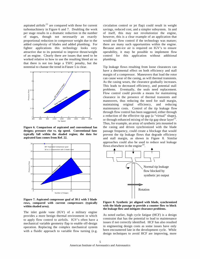
Cost, weight, and length of the engine are driven to agreat extent by the number of stages of compression(see Figures 1 and 2). The number of stages is set bywork per stage, which is limited by blade separation.Aspiration on the blade can be used to delay separation,with the added benefit of removing high entropy fluid20.Design of a single-stage fan at 3.5 pressure ratio with6% bleed, 3% each from stator and rotor, has beendescribed by Kerrebrock et al22. A longer-term goal isto reach a 30:1 compression in 3 blade rows21. Thepressure ratios that are predicted to be achievable with
5American Institute of Aeronautics and Astronautics
aspirated airfoils 22 are compared with those for currentturbomachinery in Figure 6 and 7. Doubling the workper stage results in a dramatic reduction in the numberof stages, though not necessarily an exactlyproportional reduction in compressor weight due to theadded complexity of blades and added plumbing. Forfighter applications this technology looks veryattractive due to its potential to improve thrust/weightof an engine. Clearly there are issues that need to beworked relative to how to use the resulting bleed air sothat there is not too large a TSFC penalty, but thepotential to change the trend in Figure 5 is clear.
400 600 800 1000 1200 1400 1600 1800 20001
1.5
2
2.5
3
3.5
Tip Speed
Pre
ssu
re R
ise
MIT
Asp
irated
Fan
Des
igns
Single Stage Fan Data
Figure 6. Comparison of aspirated and conventional fandesigns; pressure rise vs. tip speed. Conventional fanstypically fall within the shaded region; the data foraspirated fans comes from Ref. 22.
0 5 10 150
5
10
15
20
25
30
Number of Stages
Pre
ssu
re R
ise
MIT Aspirated Compressor goal:
30 to 1 compression with 3 blade rows
Compre
ssor
Data
Figure 7. Aspirated compressor goal of 30:1 with 3 bladerows, compared with current compressors (typicallywithin shaded area).
The inlet guide vane (IGV) of a military engineprovides a more benign thermal environment in whichto apply flow control to airfoils. IGV’s often have amechanical variable geometry flap to enable off-designoperation. Replacing the complex mechanical systemwith a fluidic approach to variable flow turning (e.g.
circulation control or jet flap) could result in weightsavings, reduced cost, and a simpler subsystem. In andof itself, this may not revolutionize the engine,however, this is a clear example of an application thatwould use flow control if the technology was mature;there are many such opportunities within the engine.Because anti-ice air is required on IGV’s to ensureoperability, it may be possible to implement flowcontrol for this application without additionalplumbing.
Tip leakage flows resulting from loose clearances canhave a detrimental effect on both efficiency and stallmargin of a compressor. Maneuvers that load the rotorcan cause wear of the casing, as will thermal transients.As the casing wears, the clearance gradually increases.This leads to decreased efficiency, and potential stallproblems. Eventually, the seals need replacement.Flow control could provide a means for maintainingclearance in the presence of thermal transients andmaneuvers, thus reducing the need for stall margin,maintaining original efficiency, and reducingmaintenance costs. Control of the tip leakage flowthrough flow control has been suggested, either througha reduction of the effective tip gap (a “virtual” shape),or through enhanced mixing of the tip gap shear layer23.Thus, for example, an array of synthetic jets mounted inthe casing and driven synchronized with the bladepassage frequency, could create a blockage that wouldprevent the tip leakage flows that degrade efficiencyand stall margin, as shown in Figure 8. Similarapproaches could also be used to reduce seal leakageflows elsewhere in the engine24.
Rotation
Normal tip leakageflow blocked bysynthetic jet output
Figure 8. Synthetic jet aligned with blade, synchronizedwith the blade passage to provide a counter flow to blockthe leakage flow and mitigate clearance problems.
As noted earlier, high cycle fatigue (HCF) is a designconstraint that has the potential to lead to maintenanceissues if not correctly identified. HCF has also resultedin engineering design costs as some issues have onlybeen encountered late in the development cycle. Whiledesign techniques to avoid HCF are improving, more

6American Institute of Aeronautics and Astronautics
highly loaded turbomachinery stages and more lightlydamped integrally-bladed rotors (IBR’s) mean thatalternative solutions could be useful. The primarysource of HCF is typically the upstream stator wake onthe rotor. This provides a harmonic excitation at Ntimes the rotation speed, where N is the number ofstators. If the speed of the engine lines up with aresonant mode of the rotor, significant stresses canresult, ultimately leading to blade fatigue. Modifyingthe wake of the upstream stator stage is one way ofsolving this problem6. Note that in addition to filling inthe wake, it is possible to selectively increase the wakein order to be orthogonal to the vibratory modes25.
A similar problem from a technical perspective is thenoise generated by the fan in a high bypass ratio engine.One major source of fan noise is rotor/stator interactionnoise, caused by wakes and turbulence from the fanrotor impinging on the downstream fan exit stator. Theperiodic unsteadiness of the wake excitation producesunsteady lift and discrete tone noise at harmonics ofblade pass frequency. The turbulence interaction withthe stator is a major source of fan broadband noise.One possible approach to reducing rotor/statorinteraction noise would be to apply trailing-edgeblowing on the rotor to fill in the wake velocity deficit.This has been studied7 in laboratory testing. Less than2% blowing led to 70-85% reductions in excitation at1x and 2x blade passage frequency. The noise benefitcould also be traded for reduced fan / stator spacing,and hence less weight.
In addition to controlling the source mechanism, thenoise radiated by the engine can also be reducedthrough better acoustic liners. Currently, acoustic linersare used in the inlet, fan case, aft bypass duct, and corenozzle to attenuate both fan and core engine noise.These passive liners are tuned to be most effective atfrequencies in the peak annoyance range (2-4 kHz).Active noise control (ANC) schemes have beenproposed for control of fan tone noise in which acircumferential array of acoustic drivers orloudspeakers is located within the inlet or aft duct,together with a set of control microphones at an axiallocation further from the fan noise source. To controlthe noise associated with the spinning duct acousticmodes typical of fan rotor/stator interaction, thespeakers are driven with phase lag that depends onfrequency and circumferential mode order. This type ofsystem has been demonstrated on scale-model fanrigs26, and is planned for full scale demonstrationtesting.
A final application to discuss briefly for the fan andcompressor system is the intermediate case (IC)between the low and high pressure compressor (LPC
and HPC). Because the low spool speed is limited bythe tip speed of the fan (in 2-spool non-geared engines),the LPC requires a high offset to keep tip speeds up andretain efficiency and reasonable work per stage. Theintermediate case must turn the flow radially inward,and is therefore limited by separation, indeed there maybe some small regions of separated flow in parts of theoperating envelope of military engines. The DirectedSynthetic Jet3 or DSJ, shown in Figure 9, is onepossible separation control approach that may beappropriate for this application. The DSJ enablescomplete reattachment of the flow through boundarylayer energization; both the instroke and the outstrokeof the synthetic jet contribute to improving theboundary layer profile. Applying separation control tothe intermediate case could enable more aggressiveturning, similar to the turbine transition duct shown inFigure 12. This would allow either a shorter transition,or a higher offset, or some combination of these. Thiscould be traded either for weight and length reductionof the IC, or to keep the LPC aft flowpath at higherradius for higher work and fewer stages.
Time-AveragedMass and Momentum
Flowδ
With Control
Acoustically driven cavity
Inflow: low x-mom
Outflow: high x-mom
Figure 9. Directed Synthetic Jet for separation control,from Reference 3. Instroke removes low momentumfluid; outstroke energizes boundary layer.
COMBUSTORKey issues in the combustor include producing auniform exit temperature profile for turbine durability,and the production of emissions. Operability is also, ofcourse, required, as instabilities can arise particularly atlow fuel-air ratios. Each of these three areas has thepotential to be addressed by flow control.
PrimaryAir Jets
DilutionAir Jets
PrimaryCombu stionZone
SecondaryCombu stionZone
Turbine In letGuide Vane s
Fuel Nozzle
Figure 10. Illustration of gas-turbine combustor

7American Institute of Aeronautics and Astronautics
The mixing zones of a gas turbine combustor are shownin Figure 10. The fuel/air ratio in the primarycombustion zone of modern high temperature risecombustors is often designed to be rich, in order tomeet operability constraints, and hence the “primary”air jets are needed to burn the remaining fuel. Thetransition from the rich primary zone to the leansecondary combustion zone must pass through thestoichiometric point, resulting in maximum flametemperatures, which is favorable for the production ofNOX. More rapid mixing here would significantlyreduce emissions production. While NOx is producedat the highest temperatures, a more important issue atlow temperatures can be CO emissions. As thetemperature increases, the CO reacts into CO2. At lowpower settings, therefore, the decreased temperatureresults in less NOx being produced, and more CO. Itmay therefore become beneficial to have less mixing,giving increased residence time at peak temperature soas to react more CO; this impacts both emissions andefficiency. Thus, in addition to technology to enhancemixing, more generally, the combustor requirescontrollable mixing. Mixing also affects operability ofthe front-end of the combustor, since combustioncannot be sustained below some minimum equivalenceratio if the fuel/air is uniformly mixed. Thuscontrollable mixing could also increase the achievableratio between maximum and minimum fuel/air. Flowcontrol is being investigated to improve mixingbehavior4. For example, pulsed injection of air throughthe primary or dilution jets, rather than steady injection,can increase jet penetration and alter mixing. Acousticexcitation can also impact mixing behavior.
Current thrust performance of gas turbine aeroenginesis limited by the peak temperature exiting thecombustor into the turbine. Turbine cooling airschemes must be designed to account for the peak gastemperature as opposed to average temperature. Inextreme cases, unburned fuel can enter the turbine, withpredictable results when contacting film cooling airintended to protect the first vane row. The relationshipbetween peak temperature and average exit temperatureis quantified by pattern factor:
PFT TT T
MAX
AVE=−−
4 3
4 3
where T4 is the gas temperature at the combustor exitand T3 is the gas temperature at the compressor exit.This pattern factor can be defined in both thecircumferential and radial directions, as well as overall.High pattern factor corresponds to a non-uniformtemperature exit distribution and can lead to reducedturbine durability. If pattern factor can be reduced by15%, it may be possible to increase engine thrust by asmuch as 20%, by operating the combustor at higher
average exit temperature (see Figure 11) and/orreducing the amount of turbine cooling air.
Allowable AverageExit Temperature
Patte
rn F
acto
r
Current
EnhancedMixing
Constraint setby maximumtemperature
Figure 11. Reduction in pattern factor enables higheraverage exit temperature
Dilution air is used to reduce combustor exit gastemperature, and the mixing of this air with the maincombustor flow helps determine the pattern factor.Also note that this process must be accomplished in theshortest distance (in the flow direction) possible, so thatthe length of the combustor can be minimized, therebydecreasing overall engine weight. As with emissionsproduction, technology to modify mixing behaviorcould therefore enable significant improvements incombustor design. Improved circumferential patternfactor could also be enabled by control of the flowthrough individual fuel nozzles. Closed loop feedbackof turbine temperature to low frequency fuelmodulation would reduce circumferential pattern factor,for example, when inlet distortion has reduced the airflow through a portion of the annulus.
Considerable effort has also gone into the developmentof control approaches for mitigating thermo-acousticinstabilities at lean (and hence low NOX) conditions27.The instability results from interaction between thecombustion heat release, and the acoustic dynamics.This unstable interaction can be controlled by pressurefeedback; actuation could employ either modulation ofthe fuel with fast response valves (typically >100 Hz),or acoustic excitation. Military engines also frequentlyemploy afterburners or augmentors, and thiscombustion process can also generate instabilities(screech) leading to maintenance costs and designconstraints. Engines currently employ screech liners inan effort to damp out these instabilities. Theseinstabilities could be controlled by modulating the fuelflow, or through shear flow actuation to directlyinfluence the unstable feedback mechanism.
TURBINEUndoubtedly the biggest challenge in turbine design isassociated with the temperature environment. As muchas 30% of the core flow is used for turbine cooling toensure durability. Maintaining reasonably constant

8American Institute of Aeronautics and Astronautics
clearance is required for efficiency, and this is currentlymanaged through scheduled thermal management of thecase. High cycle fatigue, discussed previously in thecontext of compression systems, is also an issue forturbines, as is the need to increase stage loading inorder to reduce overall engine weight and size.
One of the challenges in working in the turbine area isthe difficulty of sensing and actuating. For example,the clearance control air flow is scheduled open loop.If sensors were available to monitor clearance, thenclosed loop control could be used to maintain theinitially tight clearances as the engine wears, resultingin as much as 2% efficiency improvements at the end ofthe time on wing; longer maintenance intervals mightalso be enabled. The cooling air flow currently has novalve to allow even open loop control, but in principle,measurement of turbine inlet temperature (T4) andtemperature distribution would allow closed loopcontrol of at least part of the cooling air. This couldtherefore enable either reduced cooling flowrequirements, or higher fuel flow for the same turbinelife. A 30° error in T4 is estimated to result in a factorof 2 difference in turbine life. Noting the substantialamount of core flow required for cooling the turbine,and the substantial maintenance cost associated with theturbine, flow control technologies that improve the filmcooling effectiveness would also be valuable. Since thegoal is a layer of un-mixed cool air hugging the airfoilsurface, a concept would be required to reduce, notenhance, mixing.
In a commercial engine, the low pressure spool speed islimited by fan tip speed. In order to obtain reasonablelow pressure turbine (LPT) work per stage, a high radialoffset is used; even so, there can be many LPT stages.Aggressive transition ducts without flow separationcould reduce airfoil count and enable enhanced LPTperformance, providing substantial reductions in weightand overall propulsion system length. More aggressiveducts permit increased radial offset between the HPTand LPT, and a larger annulus area ratio across the duct,as shown in Figure 12. The increased radius results inmore LPT wheel speed so that for the same optimumloading parameter, tip speed squared over work, thenumber of stages can be reduced. Alternatively, a moreaggressive transition duct could be traded for length.The increased area ratio provides more airfoilconvergence (inlet flow area over exit flow area) in thefront stages, which allows design of more effectiveairfoil pressure distributions and improved turbineairfoil performance. The magnitude of these benefits,which would be enabled by separation control, may beroughly illustrated by imagining an aggressivetransition duct which provides a 10% increase in LPTradius. This would result in a 10% increase in tip
speed, yielding a 20% increase in work per stage, andthus would allow 20% fewer stages for a given turbinework output requirement. Such flow control enabledbenefits could lead to revolutionary changes in thedesign of next generation turbines. The temperatureenvironment rules out some flow control approachessuch as suction, or many actuator technologies;however, steady blowing or high temperature actuatedunsteady excitation are feasible.
LPTentrance
Incr
ease
dLP
T ra
dius
.
HPT exit
Figure 12. A more aggressive turbine transition ductgeometry enabled by flow control would allow an increasein low pressure turbine (LPT) radius.
0.0 100,000 200,000 300,000 400,000
Reynolds Number
0.0
-1.0
-2.0
-3.0
Engine Data
ExpectedPerformance
Cha
nge
Of E
ffic
ienc
y
Figure 13. Low pressure turbine efficiency. Performancedrops with Reynolds number.
Low pressure turbine efficiency is a strong function ofReynolds number, as shown in Figure 13. Typicalturbine efficiency drops by about 1 - 2 points betweensea level and altitude operation, and the problem canbecome more severe for high altitude flight. The reasonfor this performance shift is due to laminar separationon the turbine airfoil suction surface caused by the lowReynolds number encountered at altitude. More highlyloaded airfoils to increase stage loading and decreaseairfoil count were discussed earlier in the context of thecompressor, and this is certainly relevant for the turbineas well. Aspiration is clearly not desirable in the HPT,where gas temperatures exceed the melting point of theairfoil material. Other means of separation control maybe possible28, although care must be taken not to

9American Institute of Aeronautics and Astronautics
interfere with the film cooling. In the LPT, however,aspiration may be an option.
The compressor currently employs variable geometryturning vanes to optimize the operating point, and avoidstall. Variable geometry is challenging in the turbine,and therefore using flow control is an attractivealternative approach to obtaining flow turning normallyassociated with variable turning stators. The benefit todoing so is better accommodation of multiple turbineoperating points, widening of the airfoil loss bucket,and increasing the overall turbine operating range. Aturbine inlet guide vane would set the flow through thecore, enabling a variable cycle and potentially replacingcompressor stability bleeds.
NACELLE, INLET, and NOZZLE
The engine does not start and end with theturbomachinery; the inlet and nozzle are essential partsof the engine operation. The inlet, whether commercialor military, must provide the fan with distortion-free airwith minimum pressure losses over a wide range ofincidence angles and engine operating points. Forcommercial engines, the inlet and the aft fan ductprovide noise reduction as well. For military engines,the inlet may also be required to satisfy observabilityconstraints, while the military nozzle may be requirednot only to satisfy observability, but also to be variablein order to handle supersonic flight, afterburneroperation or to vector thrust.
Buried propulsion system installations are common formilitary engines to reduce radar cross-section (RCS),and also for some configurations of the Blended WingBody (BWB) design29,30. The S-duct inlet for suchcases may be undesirably long to avoid significantlosses, or pressure distortions that could cause theengine to stall. Flow control such as the DirectedSynthetic Jet (DSJ) in Figure 9 could be used to enablea more aggressive inlet duct without the associatedperformance penalties from separation, indeed vortexgenerators are already in use to reduce inlet distortionin some aircraft such as the F-18A/B. While inletlength is a significant propulsion/airframe integrationchallenge for manned vehicles, the inlet could become alimiting factor for the entire vehicle size for someunmanned configurations. There are other approachesone can use to avoid the strong radar return off of thespinning fan, however, these all involve some low-observables device in the front of the engine that willinevitably incur pressure loss. Flow control could beused to minimize the loss of such devices.
The inlet lip thickness on today’s subsonic turbofanengines is sized primarily for takeoff and low-speedflight performance, where the inlet must handle large
cross-winds and high-angle-of-attack operation. Acommon subsonic inlet design criterion provides forseparation-free inlet/diffuser performance up to 25°angle of attack. A typical inlet lip is shown in Figure 4.A thinner, more streamlined nacelle would reducecruise drag. Thus, applying separation control duringthe take-off and climb portions of a transport missioncould enable a thin, cruise-optimized lip. Enginesystem weight could also be reduced, and reduced sizewould improve propulsion/airframe integration.Control of inlet distortion would also help reducerequired stall margin of low-pressure-ratio turbofans.This could also enhance fan performance andoperability by providing improved take-off pressurerecovery, and reducing fan vibration.
The development path for next-generation turbofanengines leads in the direction of higher bypass ratio andlower fan pressure ratio. These features will providesubstantial improvements to propulsive efficiency andreductions in engine noise relative to current products.High bypass ratios require large engine diameters,resulting in potentially large contributions to overallaircraft drag and increasingly adverse installationeffects on the wing aerodynamics. These effects(among others) eventually offset the advantages ofhigher bypass ratios. For modern high bypass ratio(BPR~6) engines, the external nacelle drag cancontribute on the order of 3 - 5% to the total aircraftdrag, and this fraction could be higher still for next-generation turbofan engine nacelles (BPR > 10).Including internal nacelle drag increases the aircraftdrag fraction for current nacelles to as much as 8%.Strategies to reduce this can therefore have significantimpact. While one might expect increased benefitsfrom applying drag reduction strategies to the airframeand wing, the ready supply of high pressure air and theself-contained nature of the nacelle subsystem makesthe propulsion system an attractive place to firstintroduce these technologies.
Laminar flow control (LFC) has been demonstrated upto the flight test level of technology development31,32.Based upon current aircraft configurations andcommercial transport missions, net benefits of 1 – 2%reduction of overall aircraft drag are predicted fornacelle laminar flow control, which translate directlyinto an equivalent reduction of specific fuelconsumption. Natural laminar flow (NLF) systemsmaintain extended regions of laminar flow due tocareful design and shaping of the forward nacellecontour. Hybrid systems employ both a natural laminarflow region, as well as active suction within the adversepressure gradient region, to further delay transition.Although progress has been made in the area of laminarflow control, significant challenges remain. These

10American Institute of Aeronautics and Astronautics
include the cost associated with the manufacture,installation, and maintenance of suction skins and thesuction bleed source, and the sensitivity of laminarboundary layers to small (order ~ 0.001 inch) surfaceimperfections caused by insect or debris strikes,manufacturing tolerances/defects, or natural jointsproduced in the nacelle construction.
Methods of controlling the near-wall boundary layerflow beneath fully turbulent boundary layers providealternatives to laminar flow control. Riblets have beenstudied for many years in much detail as a means toachieve skin friction drag reduction on propulsionsystems and aircraft wings. The interest level in thesedevices has been high due to their passive nature andoverall simplicity. Maximum riblet drag reductionlevels, based upon previous studies available in theopen literature, are in the 5 – 15% range33,34,35. A studyby Lynch and Klinge11 points out some of the economicdrawbacks associated with implementing riblets onaircraft. Costs associated with the initial ribletinstallation by the manufacturer, combined withmaintenance/cleaning costs and the cost of re-installingthe riblet material approximately every 5 years, offsetmuch if not all of the achievable riblet drag reductionbenefit.
Surface mass injection is another method for turbulentboundary layer drag reduction, both in terms ofdistributed normal mass injection as well as tangentialslot injection36,37. Normal blowing with conventionalhole sizes suffers from the problem of large effectiveroughness increases of the perforated surfaces. Normalblowing through micro-perforate skins has been shownrecently to combine the effectiveness of normal massinjection for skin friction drag reduction with a poroussurface possessing low effective roughness38. This isachieved by using micro-sized holes of the properdimension and shape. This concept has beensuccessfully demonstrated on a large-scale nacellemodel at flight Reynolds numbers to achieve skinfriction reductions on the order of 50% over a portionof the nacelle8. Again, challenges remain regarding thecost and weight of such a system, and engine cyclepenalties associated with the required steady source ofbleed air. Combining two or more flow controlconcepts that possess complementary features wouldhelp minimize such installation penalties. For example,utilizing the flow removed from aspirated compressorblades as a blowing source for micro-porous massinjection elsewhere in the engine would be an attractivealternative to scheduling bleed air for this function.
The aft end of the nacelle forms the nozzle for the fanduct. In commercial and military transportapplications, flow control that allows for different fan
nozzle flow areas between take-off and cruise wouldenable new, high-efficiency engine cycles. Fan surgemargin requirements presently limit the degree to whichlow fan pressure ratio (and hence high propulsiveefficiency) engine cycles may be implemented. For anext-generation, high-bypass ratio long rangecommercial turbofan (BPR > 10) it is estimated that upto 20% fan nozzle area control would be required inorder to enable fan operation and associated TSFCengine cycle benefits on the order of 5% and higher.For high bypass ratio engines, this represents asignificant amount of fan flow needing to be controlled.Variable fan nozzle area could also provide aircraft trimcontrol to optimize engine performance during flight,and combined with trim vectoring of the fan nozzlethrust, could further optimize overall aircraft cruisedrag during a transport mission. Finally, flow controlthat enables the control of fan nozzle area can provideimportant acoustic benefits as well. Quiet enginecycles are associated with the resulting reduced fanpressure ratio (and hence reduced tip speed) and lowerfan stream jet velocities that this capability provides.
The nacelle on subsonic transports also typically has athrust reverser, also in the fan duct region, whichdiverts the fan stream radially outward and forward toreverse thrust immediately after landing. A cascade-type thrust reverser consists of a movable cowl thattranslates aft to expose a set of cascade vanes, and ablocker door that deploys simultaneously to force thefan air through the cascade rather than out the nozzle.Target-type reversers deploy flow-impingementhardware external to the nozzle. The engine flow hitsthe target, and is directed outward and forwards. Pivotdoor reversers perform in a similar manner, but deployflow-impingement hardware within the nacelle. Thesesystems work, but add substantial weight, particularlywhen one considers what fraction of the total enginelife cycle that they operate. Thrust reversers can beresponsible for more than half the cost of the entirenacelle subsystem. A blockerless system has beenproposed that uses fluidic actuation/flow blockageinstead of mechanical variable geometry.39 Note thatthe efficiency of such a system is less critical for thisapplication because of when it is being used;nonetheless, a substantial quantity of air must bediverted using air from the core stream, and hence thisremains a challenging application.
A final application to consider for the commercialengine is that of controlling jet noise. Engine noise hasdecreased considerably over the last 30 years, however,total aircraft traffic has increased, so that communitynoise remains an increasing problem. Primary enginenoise sources include the fan, as discussed earlier, andjet noise. For current engines, both jet and fan noise are

11American Institute of Aeronautics and Astronautics
roughly comparable sources of noise. The jet noise iscreated by turbulent mixing aft of the engine, anddriven primarily by the difference in jet velocity andtemperature between the engine exhaust and theambient air. For separate flow nacelles (where the fanand core streams are not mixed within the engine, e.g.as in Figure 4), there are two shear layers where noisecan be produced. Noise reductions to date have beenobtained purely through reductions in jet velocity,either by increasing bypass ratio (which also increasespropulsive efficiency), or through enhanced mixingusing devices such as internal lobed mixers or mixer-ejectors40,41,42. Internal lobed mixers and mixer-ejectorshave been successfully deployed on 727 and 737aircraft during the 1990’s to reduce jet noise to stage 3levels. Recent research, however, has created somehope for reducing noise by modifying the dynamics ofthe mixing process itself. A discussion of the problemand some potential flow control solutions can be foundin Seiner43. The relationship between mixing and theresulting noise is not yet well understood, and thereforeit isn’t clear what control should do to the flow in orderto improve noise44. Several passive devices haveshown some promise, these include tabs45, or anappropriately flexible wire trailing behind the core46,however, the physics behind these approaches is notcertain. Active control approaches have also beensuggested, based on favorable modification of the jetstructure47. Regardless of the solution, reductions in jetnoise would be highly valuable, and are being activelypursued in the engine noise community.
The nozzle on high performance military aircrafttypically provides additional functions. When theafterburner is operational, the nozzle throat area A8must increase by as much as a factor of 2. Replacingthe current mechanical system with a fluidic approachcould reduce weight, cost, and improve integration withthe airframe. As with any application, any performanceloss incurred would need to be taken into account inoverall system trades. In addition to changing the exitarea, the nozzle on high performance tactical aircraftalso provides the ability to vector the engine thrust.This can provide substantial improvements in aircraftmaneuverability. Current generation aircraft such asthe PW-F119 powered F-22 Raptor have pitchvectoring capability on the order of 20° to providesuper-maneuverability. Similar capability in yawvectoring might enable reductions in aircraft verticaltail area and associated LO penalties. The currentvectoring systems involve complex mechanical variablegeometry with significant added weight and cost, andmay present a challenge with airframe integration,particularly for an LO configuration. Fluidic nozzletechnology that implements both expansion ratiocontrol and thrust vectoring without the current
mechanical complexity would therefore be extremelyvaluable48,49,50,51. Fluidic thrust vectoring is used inrocket engines today. For gas-turbine engines, severalfluidic mechanisms have been proposed for thrustvectoring, including shock-vector turning in thedivergent section, and throat-skewing, as shown inFigure 14. Lockheed Martin has carried outcomputational and experimental studies of fluidicnozzle throat area and thrust vector control49, as shownin Figure 15. This work demonstrated that effectivethrust vectoring could be accomplished through fluidicskewing of the nozzle throat, a relatively low-loss,subsonic mechanism. In order to accomplish fluidicthrust vectoring at realistic flight conditions, 1% ofinjected flow for every 1.5 degrees of vector angle wasrequired. This substantial bleed flow requirementdictates the need for continued research in this area.Note that while there are substantial aircraft systembenefits, a useful fluidic system must not incur otherpenalties such as excessive added base drag.
Fluidic Throat Skewing Shock Vector Control
Vector and Throat Area ControlSmall Impact to Cfg
Favors Small Divergence AngleSmall NPR Effect
Vector Control OnlyModerate to Large Cfg LossFavors Large Divergence AngleModerate NPR Effect
subsonicturning
supersonicturningshock
injector
injector
injector
Figure 14. Characteristics of Fluidic Throat Skewing &Shock Vector Control for Jet Flow Control, from Ref. 49.Copyright 1999 Lockheed Martin. Reprinted withPermission.
ThroatInjector
FlapInjector
SonicPlane
Thrust VectorAngle
Figure 15. Fluidic Throat Skewing CFD Solution PressureContours: Red-High, Blue-Low Conditions: Mach 0.9,36,000 ft, NPR=5.5, from Ref. 49. Copyright 1999Lockheed Martin. Reprinted with Permission.

12American Institute of Aeronautics and Astronautics
Flow control could also be used for more rapid mixingof the exhaust jet, to enable more rapid reduction in thetemperature 52. For flight, this has obvious IR benefits.The work in Reference 52 involves pulsed injection ofcompressor bleed air into the core exhaust to excite thejet flapping mode, resulting in much more rapid mixing.This technology is intended for deployment on the C-17transport for use while the aircraft is on the ground.The improved mixing enables the ground crew to loadthe aircraft while the engine is running, for rapid turn-around, without having to resort to a heavy and costlycore thrust reverser system. Because this aircraft has ablown flap for high lift, temperature reduction can alsoreduce material costs required for protection from jetimpingement. Finally, modification of the shape of thejet could increase the area of the flap assisted by engineexhaust, thus improving the high lift capability of theaircraft.
ISSUES
The potential for flow control to impact gas-turbineengine design is clearly significant. However, for anysuch technology to make it on to the product, systemtrade studies are required. It is not sufficient toimprove a component, one must look at the overallsystem and consider total value to customer, includingadded cost and weight, additional complexity andresulting maintenance or availability cost, and the risksincurred by the engine program if the technology is notthoroughly understood. Reliability is an absoluterequirement; for flight critical systems, failure rates of10-9 per flight are required. Current commercialengines achieve in-flight shutdown rates better than0.0026 in 1000 hours.
For many of the flow control applications discussed, themaximum benefit is obtained if the propulsion system isdesigned around the technology. The mostrevolutionary benefits are typically achieved when afundamental design constraint is removed. As a result,many applications are much less attractive as a retrofitoption. Thus for example, implementing the aspiratedcompressor requires thinking about where to use bleedair. Many more options are available with a clean sheetof paper than if one is considering a retrofit onto anexisting engine. Such an analysis has been performedfor this case; a design study considered the retrofit of asingle aspirated stage to replace the current 3-stage fanon the PW100-229. While many issues were identified,including estimates of weights and manufacturing costs,the analysis indicated a net increase in life cycle cost,based largely on TSFC penalty and addedmanufacturing cost from hollow blades. This notsurprising result simply emphasizes that for dramaticchanges in fundamental design constraints, significant
changes in the overall engine design will be required totake advantage of this capability.
In addition to the system issues, the gas turbine engineprovides a challenging environment within which towork. The primary issue is temperature. Gas-pathtemperatures throughout the engine are shown in Figure16; this plot is already slightly dated in terms oftemperatures reached in modern commercial engines,and military values are higher still. The case tends tobe cooler, but can still reach 1000°F. Actuation andsensing must survive this harsh environment, must beextremely reliable, must not add excessive weight, andmust not add excessive cost despite the relatively lowproduction volumes.
Figure 16. PW 4000 engine gas-path temperatures (fromRef. 53)
CONCLUDING REMARKSFlow control has the potential to make a significantimpact on the turbofan engine. The ability to design thedesired fluid dynamic behavior has always been the keyto designing gas turbine engines. Flow control has thepotential to be a breakthrough technology that enables astep change in our ability to design the fluid mechanics,and break fundamental barriers that limit performance.Future engines that incorporate a range of thesetechnologies may be able to yield dramaticimprovements in key metrics and change theasymptotic nature apparent in plots such as Figure 5.
We have consciously chosen not to prioritize theapplications listed herein. There are three relatedreasons for this. First is that some of the applicationsare more technically challenging than others, and theprioritization should be based on both impact andtechnical risk. All of the applications have potentialimpact, and it may be that demonstrating technology ina less risky but lower impact application becomes thepathway by which the concepts get proven out and

13American Institute of Aeronautics and Astronautics
ultimately implemented across a range of applications.Second is that the value depends on both the benefits,and the costs (in terms of cost, weight, maintenanceimpact, etc) of a particular solution, and thus cannot bedetermined solely on the application alone. Third isthat the relative value of overcoming different problemsmay differ for different aircraft and enginecombinations, or different missions. If a technologymakes the difference between being able to fit anengine into a particular airframe or not, or meeting aregulatory constraint or not, then the value can becomesubstantially larger than expected.
The above comments notwithstanding, it is likely thatflow control implementation within the turbofan enginewill follow paths which are linked to the most provenand reliable technology first. Thus, the more near-termapplications are likely to involve extensions of elementscurrently in use (such as utilizing scheduled air forblowing in new separation control or coolingapplications). In addition, it is felt that low-temperature, fixed engine components offer in generalfewer challenges relative to actuation authority,robustness, integration, and flow control subsystemreliability. Examples would include the subsonic inletat takeoff, the fan nozzle, fan case, and fan exit guidevane. Within the mid-portion of the engine wouldcome the next set of challenges as temperaturesincrease within again fixed geometry flowpaths such asturbine transition ducts, the intermediate case, and lowpressure turbine guide vanes. Finally, the greatestchallenges and likely least-near-term applications lie inthe hot sections of the engine and on the rotatingmachinery airfoils themselves. High temperature, highMach number, structural and rotational loads, andpackaging are significant challenges in creating areliable and functional flow control subsystem.
It is likely that non-flight critical applications will seeimplementation prior to those that are flight critical.This includes such things as improvements in fuel burnor noise, rather than those that impact durability wherefailure means the loss of the engine and airframe. Theengineer who has to put a product out the door isnecessarily conservative and can only consider proventechnology. The biggest barrier, therefore, may be theperception of a lack of reliability. Uninhabited airvehicles may also pose a more near-term technologyinsertion path, because the flight safety issue is notnearly so paramount.
As mentioned above, specific application needs andgoals will ultimately drive the final prioritization offlow control technology development. This discussionpresents one view of a possible near-term class of gas
turbine engine flow control applications based uponoverall complexity and challenge.
ACKNOWLEDGEMENTSA broad paper such as this is ultimately the result of thecomments and suggestions of many people. Almostevery paragraph corresponds to a conversation one ofthe authors has had with someone, and thus it isimpossible to acknowledge everyone who influencedthis paper. However, special thanks are due to JeffCohen of UTRC (combustion mixing), Bob Neubert ofPratt & Whitney (aspirated compressor benefitsanalysis), Mike Larkin of Pratt & Whitney (nacelleaerodynamics), Dick Price and Joel Wagner of Pratt &Whitney (turbine aerodynamics), Eric Gamble and NateMessersmith of Pratt & Whitney (fluidic nozzletechnology) and Dan Miller of Lockheed Martin(fluidic nozzle work in Figure 14 and 15), and DuaneMcCormick of UTRC (DSJ in Figure 9).
REFERENCES 1 Prandtl, L. “Über Flüssigkeitsbewegung bei sehrkleiner Reibung”, Proceedings, 3rd InternationalMathematics Congress, Heidelberg, Germany, pp. 484-491, 1904.2 Wygnanski, I, “Method and Apparatus for DelayingSeparation of Flow from a Solid Surface”, US Patent5,209,438, 1993.3 McCormick, D.C. “Boundary Layer SeparationControl with Directed Synthetic Jets”, AIAA 00-0519,AIAA Aerospace Sciences Conference, Reno NV, 2000.4 Vermuelen, P.J., Grabinski, P. and Ramesh, V.,“Mixing of an Acoustically Excited Air Jet With aConfined Hot Crossflow,” ASME Journal ofEngineering for Gas Turbines and Power, Vol 114,pp. 46-54, April 1992.5 Smith, B.L. and Glezer, A., “Vectoring and Small-Scale Motions Effected in Free Shear Flows UsingSynthetic Jet Actuators”, AIAA 97-0213, 35th
Aerospace Sciences Conference, Reno, NV, 1997.6 Rao, N.M., Feng, J., Burdisso, R.A., and Ng, W.F.,“Active Flow Control to Reduce Fan Blade Vibrationand Noise”, 5th AIAA/CEAS Aeroacoustics Conference,AIAA 99-1806, Seattle, WA, May 1999.7 Brookfield, J.M., and Waitz, I.A., “Trailing EdgeBlowing for Reduction of Turbomachinery Fan Noise”,4th AIAA/CEAS Aeroacoustics Conference, AIAA 98-2321, June 1998.8 Tillman, T. G. and Hwang, D. P., “Drag Reduction ona Large-Scale Nacelle Using a Micro-BlowingTechnique”, AIAA 99-0130, AIAA Aerospace SciencesConference, Reno, NV, 1999.9 Bewley, T.R., Moin, P., and Temam, R., “DNS-basedpredictive control of turbulence: an optimal benchmark

14American Institute of Aeronautics and Astronautics
for feedback algorithms”, under consideration for J.Fluid Mechanics.10 Gad-el-Hak, M., “Introduction to Flow Control”, inFlow Control: Fundamentals and Practices, Springer-Verlag, 1998, pp. 1-108.11 Lynch, F. T., and Klinge, M. D., “Some PracticalAspects of Viscous Drag Reduction Concepts,” SAEPaper 912129, Sept. 1991.12 Aviation and the Global Atmosphere, A special reportof Working Groups I and III of the IntergovernmentalPanel on Climate Change,http://www.usgcrp.gov/usgcrp/IPCCINFO.html13 Jane’s All the World’s Aircraft.14 McMichael, J.M., “Progress and Prospects for ActiveFlow control Using Microfabricated Electro-Mechanical Systems (MEMS)”, 34th AerospaceSciences Conference, Reno NV, 1996. AIAA 96-0306.15 Grzybowski, R.R., “Advances In PackagingTechnologies For Electronics To 500°C,” Proceedingsof Engineering Foundation 1998 High-TemperatureElectronic Materials, Devices and Sensors Conference,San Diego, CA, Feb. 1998, pp. 207 - 215.16 Grzybowski, R.R., “Long Term Behavior of PassiveComponents For High Temperature Applications”Proceedings of Engineering Foundation 1998 High-Temperature Electronic Materials, Devices and SensorsConference, San Diego, CA, Feb. 1998, pp. 172 - 179.17 de Jager, B., “Rotating Stall and Surge Control: ASurvey”, Proceedings, 34th IEEE Conference onDecision and Control, New Orleans, LA, 1995,pp. 1857-1862.18 Eveker, K.M., Gysling, D.L., Nett, C.N., and Sharma,O.P., “Integrated Control of Rotating Stall and Surge inHigh-Speed Multi-Stage Compression Systems,” ASMEJ. Turbomachinery, 120(3), July 1998, pp. 451-45719 D'Andrea, R., Behnken, R.L., Murray, R.M. “ActiveControl of an Axial Flow Compressor via Pulsed AirInjection,” J. Turbomachinery, 119(4):742-752, 1997.20 Kerrebrock, J.L., Reijnen, D.P., Ziminsky, W.S.,Smiig, L.M., “Aspirated Compressors”, ASME 97-GT-525, Orlando, FL, 1997.21 Freedman, J.H., Design of a Multi-Spool, High SpeedCounter-Rotating, Aspirated Compressor, MS Thesis,Dept. of Aeronautics and Astronautics, MIT,June 2000.22 Kerrebrock, J.L., Drela, M., Merchant, A.A., Schuler,B.J., “A Family of Designs for AspiratedCompressors,” International Gas Turbine &Aeroengine Congress, ASME 98-GT-196, 1998.23 Bae, J., Breuer, K., Tan, C., “Active Control of TipClearance Flows in Axial Compressors”, Fluids 2000,AIAA 2000-2233, Denver, CO, June 2000.24 Kang, E., Breuer, K., Tan, C. “Control of LeakageFlows using Periodic Excitation”, Fluids 2000, AIAA2000-2232, Denver, CO, June 2000.
25 El-Aini, Y.M., Benedict, B. et al. “Active rotor stagevibration control,” Patent # 6055805, May 2, 2000.26 Walker, B.E., Hersh, A.S., Heidelberg, L.J., Sutliff,D.L, Spencer, M.E., “Active Resonators for Control ofMultiple Spinning Modes in an Axial Flow Fan Inlet,”5th AIAA/CEAS Aeroacoustics Conf., May 1999, SeattleWA.27 Cohen, J.M., Rey, N.M., Jacobson, C.A. andAnderson, T.J., “Active Control of CombustionInstability in a Liquid-Fueled Low-NOx Combustor,”ASME Journal of Engineering for Gas Turbines andPower, Vol. 121, No. 2, pp. 281-284, April 1999.28 Bons, J.P., Sondergaard, R., Rivir, R.B., “TurbineSeparation Control using Pulsed Vortex GeneratorJets,” TurboExpo 2000, Munich, Germany. ASMEpaper 2000-GT-0262.29 Anabtawi, A.J., Blackwelder, R.F., Lissaman, P.B.S.,and Liebeck, R.H., “An Experimental Investigation ofBoundary Layer Ingestion in a Diffusing S-Duct withand without Passive Flow Control”, 37th AIAAAerospace Sciences Conference, Reno NV, 1999.AIAA paper 99-0739.30 Anabtawi, A.J., Blackwelder, R.F., Lissaman, P.B.S.,and Liebeck, R.H., “An Experimental Study of VortexGenerators in Boundary Layer Ingesting Diffusers witha Centerline Offset”, 35th AIAA/ASME/SAE/ASEE JointPropulsion Conference, LA, CA, 1999. AIAA paper99-2110.31 Barry, B., Parke, S.J., Brown, N.W., Riedel, H., andSitzmann, M., “The Flight Testing of Natural andHybrid Laminar Flow Nacelles,” ASME Paper 94-GT-408, June 1994.32 Runyan, L.J, Bielak, G.W., Behbehani, R. Chen,A.W., and Rozendaal, R.A., “757 NLF Glove FlightTest and Results”, Research in Natural Laminar Flowand Laminar Flow Control, J.H. Hefner and F.E. Sabo,compilers, NASA CP-2487, Part 3, pp. 795-818, 1987.33 Stockman, N.O., Latapy, M.O., Andrew, T.L., andRogers, D.H., “Scale Model Test of an IsolatedTurbofan Nacelle with Riblets”, SAE Paper 912128,Sept. 1991.34 Neiuwstadt, F.T.M., Wolthers, W., Leijdens, H.,Krishna Prasad, K., and Schwarz-van Manen, A., “Thereduction of skin friction by riblets under the influenceof an adverse pressure gradient,” Experiments in Fluids,Vol. 15, pp. 17-26, 1993.35 Debisschop, J.R., and Nieuwstadt, F.T.M.,“Turbulent Boundary Layer in an Adverse PressureGradient: Effectiveness of Riblets,” AIAA Journal,Vol. 34, No. 5, May 1996.36 Hefner, J.N., and Bushnell, D.M., “Viscous DragReduction via Surface Mass Injection,” In ViscousDrag Reduction in Boundary Layers. AmericanInstitute of Aeronautics and Astronoutics, Inc., 1989.

15American Institute of Aeronautics and Astronautics
37 Schlichting, H., Boundary Layer Theory. 7th Edition,McGraw-Hill, New York, 1979.38 Hwang, D.P., “A Proof of Concept Experiment forReducing Skin Friction by using a Micro-BlowingTechnique”, AIAA Paper 97-0546, Jan. 1997.39 Marconi, F., Gilber, B., Tindell, R., “ComputationalFluid Dynamics Support of the Development of aBlockerless Engine Thrust Reverser Concept”, AIAA97-3151, AIAA/ASME/SAE/ASEE Joint PropulsionConference, Seattle, WA, July 1997.40 Lord, W.K., Jones, C.W., Stern, A.M., Head, V.L.,and Krejsa, E.A., “Mixer Ejector Nozzle for Jet NoiseSuppression.” AIAA Paper 90-1909, July 1990.41 Tillman, G.T., Paterson, R.W., and Presz, W.M., Jr.,“Supersonic Nozzle Mixer Ejector.” AIAA Journal ofPropulsion and Power, Jan.-Feb. 1992.42 Paterson, R.W., “Turbofan Mixer Nozzle Flowfield-A Benchmark Experimental Study,” Journal ofEngineering for Gas Turbines and Power, Vol. 106,July 1984, pp. 692-698.43 Seiner, J.M., “A New rational Approach to Jet NoiseReduction”, Theoretical and Computational FluidDynamics, Vol 10, 1998, pp. 373-383.44 Simonich, J.C., Narayanan, S., Barber, T.J.,Nishimura, M., “High Subsonic Jet Experiments Part I:Aeroacoustic Characterization, Noise Reduction andDimensional Scaling Effects”, 6th AIAA/CEASAeroacoustics Conference, Lahaina, HI, 2000. AIAAPaper 2000-2022.45 Zaman, K.B.M.Q., “Effects of Delta Tabs on Mixingand Axis Switching in Jets from AxisymmetricNozzles”, 32nd AIAA Aerospace Sciences Conf., RenoNV, 1994. AIAA Paper 94-0186.46 Anderson, B., Wygnanski, I., and Gutmark, E.,“Noise Reduction by Interaction of Flexible Filamentswith an Underexpanded Supersonic Jet,” 37th AIAAAerospace Sciences Conf., Reno NV, 1999. AIAApaper 99-0080.47 Corke, T., Glauser, M.N., Berkooz, G., “UtilizingLow Dimensional Dynamical Systems to Guide ControlExperiments,” Applied Mechanics Review, 47, 6,pp. 133-138, 1994.48 Gridley, M.C. and Walker, S.H., “Inlet and NozzleTechnology for 21st Century Aircraft”, ASME 96-GT-244.49 Miller, D.N., Yagle, P.J., Hamstra, J.W., “FluidicThroat Skewing for Thrust Vectoring in FixedGeometry Nozzles”, Paper AIAA 99-0365, 37th AIAAAerospace Sciences Conference, Reno NV, 1999.50 Giuliano, V.J; Wing, D.J, “Static investigation of afixed-aperture nozzle employing fluidic injection formultiaxis thrust vector control,”, AIAA Paper 97-3149,33rd AIAA/ASME/SAE/ASEE Joint PropulsionConference & Exhibit, Seattle, WA, July 6-9, 1997.
51 Anderson, C.J; Giuliano, V.J; Wing, D.J,“Investigation of hybrid fluidic/mechanical thrustvectoring for fixed-exit exhaust nozzles,” AIAA Paper97-3148, 33rd AIAA/ASME/SAE/ASEE Joint PropulsionConference & Exhibit, Seattle, WA, July 6-9, 1997.52 Kibens, V., Dorris III, J., Smith, D.M., Mossman,M.F., “Active Flow Control Technology Transition:The Boeing ACE Program”, AIAA 99-3507.53 The Aircraft Gas Turbine Engine and its Operation,United Technologies Corporation, 1988.


![Asian Architecture [ARC 2234] Case Study Paper](https://img.pdfslide.net/doc/110x75/55cf94ff550346f57ba5d984/asian-architecture-arc-2234-case-study-paper.jpg)