Embed Size (px)
Citation preview
AIC Computations Using Navier-Stokes Equations on Single Image Supercomputers For Design Optimization
Guru Guruswamy* NASA Advanced Supercomputing Division
Ames Research Center. Moffett Field, CA, U.S.A.
Introduction
Aeroelasticity that involves strong coupling of fluids and structures is an important element in the design and optimization of aerospace vehicles. Large general purpose codes such as ASTROS[l] and NASTRkhJ[2] can compute the aeroelasticity of complex geometries using finite element (FEM) structures and linear aerodynamic equations. These codes use the AIC (aerodynamic influence coefficient) approach to couple fluids and structures. The concept of using AIC for aeroelastic computations was introduced several years ago [3]. The piston theory proposed for supersonic flows[4] introduced the AIC concept that became suitable with the finite element structural analysis approach. The early effort in developing the AIC approach compatible with FEM was pieseiited by Appa et. al.[5 3
Several real world examples have shown that linear aerodynamic theory is not adequate for accurately predicting the aeroelasticity associated with complex flows. Modem supersonic transports that have highly swept wings can experience vortex- induced aeroelastic oscillations [6]. In order to predict this phenomenon, a capability to directly couple the high fidelity EulerAlavier-Stokes (ENS) equations with modal structures was needed[7]. As another example, the aeroelasticity of space planes that involve strong coupling of fluids, structures and controls is an important element in the design process An instability can occur soon after the space plane is separated from its canier. The phenomenon is dominated by complex flows coupled with structural motions. From the results presented in Ref. 8 it is observed that the linear aerodynamic method was not adequate to completely understand the instability phenomenon which involved non-linear flows coupled with structural motions. High fidelity equations such as EulerNavier- Stokes (ENS) for fluids directly coupled with finite elements (E) for structures are needed for accurate aeroelastic computations in which these complex fluiflstructure interactions exist. Use of high- fidelity equations in\7olves additional complexities that result from numerics such as higher-order terms. Therefore, the coupling process is more elaborate when using high fidelity methods than it is for calculations using linear methods.
* Sr Research Scientist
t
In recent years efforts have begun to improve the fidelity of AIC using non-linear CFD computations in place of linear aerodynamics. In Ref. 9 an approach to correct the AIC approach based on linear aerodynamic theory by using the steady state Navier-Stokes solutions is presented for cases with small deflections. Reference 10 presents use of the Euler equations to compute AIC using transpirent boundary conditions for cases with small deflections. In bath approaches, AICs are computed without deforming CFD grids. For accurate computations of AIC which are valid for real world cases it is necessary to deform CFD grids. Efficient CFD methods that account for moving grids have been developed. Reference 1 1 presents a procedure for modeling configurations with moving rigid components using overset grids. In Ref. 12 a capability to model flows over flexible configurations with multi-block moving patched grids is presented. Based on these developments AIC computational accuracy can be increased by accounting for the effects moving grids.
The AIC approach involves dividing the configuration into several panels based on structural details. Responses are then computed for several types of perturbations at different frequencies. For accurate computations each panel needs to be perturbed for 12 modes, 9 strained and 3 rigid body modes [6] , at about 5 frequencies. A typical space plane such as the X-37 [13] needs about 200 panels which leads to a total of about 12000 cases for each Mach number. As a result, it requires enormous anount of computational resources. Such resources can be efficiently provided by single-image massively parallel supercomputers.
NASA has facilitated development of large scale parallel computers since early 90’s [ 141. Recently NASA in collaboration with Intel corporation and SGI has announced commissioning one of the world’s largest supercomputer that will be 10 times faster than the current ones[l5]. As a result, computing CFD based AIC for aerospace design is becoming a feasible approach.
This paper presents a procedure to efficiently compute AIC using the Navier-Stokes equations associated with deforming grids.
Approach
For a given configuration a suitable CFD grid is generated. From this the surface grid is extracted. Based on the CFD surface grid, AIC panels are defined. Each AIC panel is subjected to various modal motions to generate the aerodynamic coefficients and determine corresponding influence on other panels. Computation for each mode and frequency is assigned to a separate processor.
Separate inputs are needed for each panel. An automated procedure that generates the panel input data is written in C++. Multiple cases are run using PBS (Portable Batch System) job control language[ 161 that has the ability to spawn cases to different
0 I c
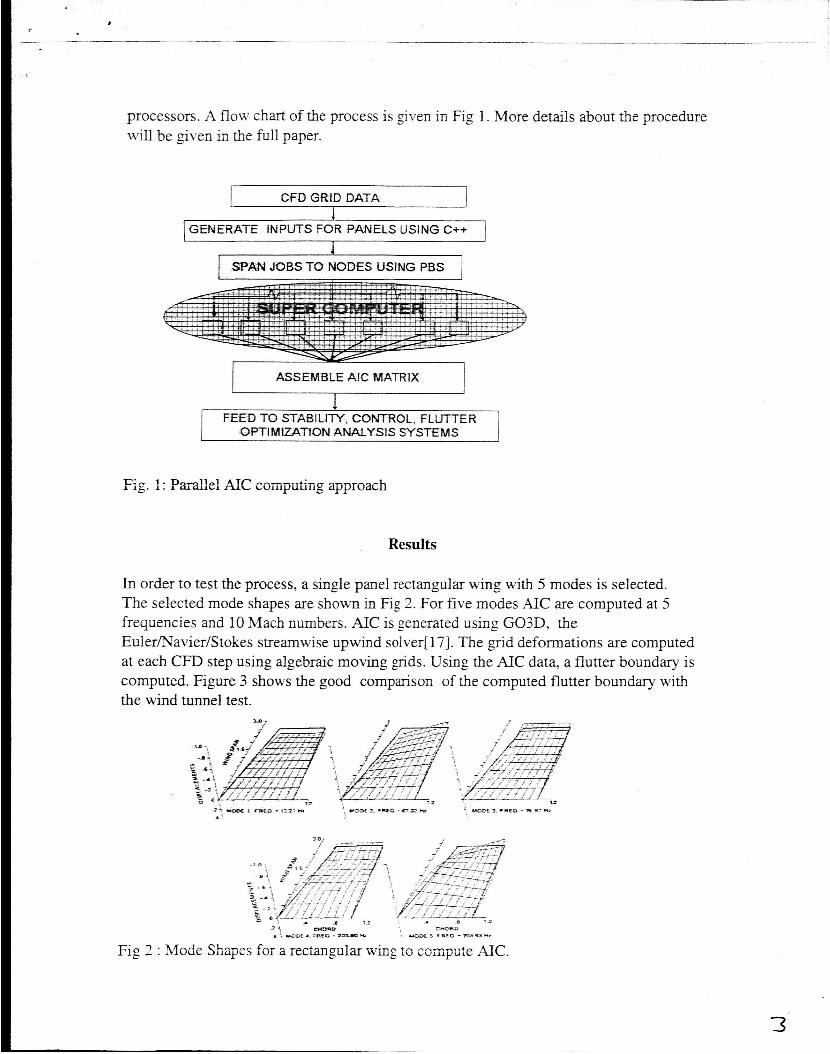
processors. A flow chart of the process is given in Fig 1. More details about the procedure will be given in the full paper.
CFD GRiD DATA
1 GENERATE INPUTS FOR PANELS USING C++ I t
I SPA54 JOBS TO NODES UStNG PBS 1
ASSEMBLE AJC MATRIX
OPTlMiZ4TtON ANALYSIS SYSTEMS
Fig. 1 : .Parallel AXC computing apimxich
Results
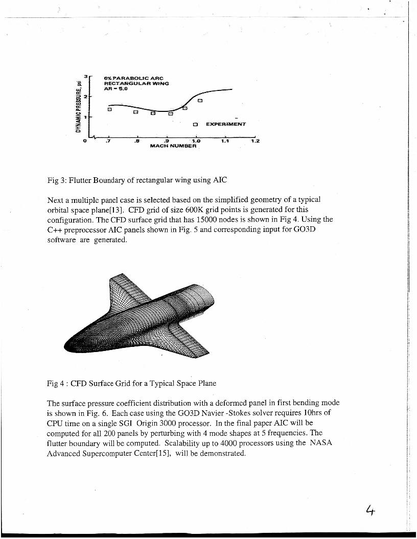
In order to test the process, a single panel rectangular wing with 5 modes is selected. The selected mode shapes are shown in Fig 2. For five modes AIC are computed at 5 frequencies and 10 Mach numbers. AIC is generated using G03D, the Euler/Navier/Stokes streamwise upwind solver[ 171. The grid deformations are computed at each CFD step using algebraic moving grids. Using the AIC data, a flutter boundary is computed. Figure 3 shows the good comparison of the computed flutter boundary with the wind tunnel test.
UUmD C Y u D :I, - 4 F I f O - 10910 * Fig 2 : Mode Shapes for a rectangular wing to compute AIC.
> - s * ~ a - m 3 * 3 *
3'
6% P A R A m f C A= RECTANGULAR WING AR - 5.0
Fig 3: mutter Boundary of rectangular wing using AIC
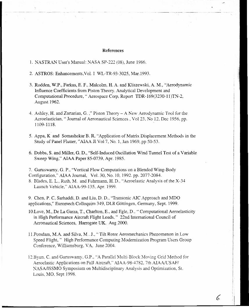
Next a multiple panel case is selected based on the simplified geometry of a typical orbital space plane[ 131. CFD grid of size 600K grid points is generated for this configuration. The CFD surface grid that has 15000 nodes is shown in Fig 4. Using the C++ preprocessor AIC panels shown in Fig. 5 and corresponding input for G03D software are generated.
Fig 4 : CFD Surface Grid for a Typical Space Plane
The surface pressure coefficient distribution with a deformed panel in first bending mode is shown in Fig. 6. Each case using the G03D Navier -Stokes solver requires lOhrs of CPU time on a single SGI Origin 3000 processor. In the final paper AIC will be computed for all 200 panels by perturbing with 4 mode shapes at 5 frequencies. The flutter boundary will be computed. Scalability up to 4000 processors using the NASA Advanced Supercomputer Center[ 151, will be demonstrated.
4
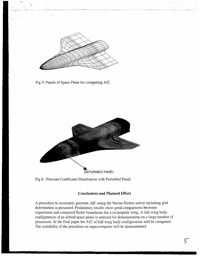
Fig 5: Panels of Space Plane for computing AIC.
\ DEFORMED PANEL
Fig 6 : Pressure Coefficient Distribution with Perturbed Panel
Conclusions and Planned Effort
A procedure to accurately generate AIC using the Navier-Stokes solver including grid deformation is presented. Preliminary results show good comparisons between experiment and computed flutter boundaries for a rectangular wing. A full wing body configuration of an orbital space plane is selected for demonstration on a large number of processors. In the final paper the AIC of full wing body configuration will be computed. The scalability of the procedure on supercomputer will be demonstrated.
References
1. NASTRAN User’s Manual: NASA SP-222 (08), June 1986.
2. ASTROS: Enhancements,Vol. I WL-TR-93-3025, Mar. 1993.
3. Rodden, W.P., Farkas, E. F., Malcolm, H. A. and Kliszewski, A. M., “Aerodynamic Influence Coefficients from Piston Theory. Analytical Development and Computational Procedure, “ Aerospace Corp, Report TDR- 169(3230-11)TN-2, August 1962.
4. Ashley, H. and Zartarian, G. ,” Piston Theory - A New Aerodynamic Tool for the Aeroelastician, “ Journal of Aeronautical Sciences , Vol23, No 12, Dec 1956, pp. 1 109- 11 18.
5. Appa, K and Somashekar B. R, “Application of Matrix Displacement Methods in the Study of Panel flutter, ”M4.A 31 ’dol 7, No. 1, Jan 1969, pp 50-53.
6. Dobbs, S . and Miller, G. D., “Self-Induced Oscillation Wind Tunnel Test of a Variable Sweep Wing,” AIAA Paper 85-0739, Apr. 1985.
7. Guruswamy, G. P., “Vortical Flow Computations on a Blended Wing-Body Configuration,” AIAA Journal, Vol. 30, No. 10, 1992. pp. 2077-2084. 8. Blades, E. L., Ruth, M. and Fuhrmann, H. D., “Aeroelastic Analysis of the X-34
Launch Vehicle,” AIAA-99- 135, Apr. 1999.
9. Chen, P. C, Sarhaddi, D. and Liu, D. D., “Transonic AIC Approach and MDO applications,” Euromech Colloquim 349, DLR Gottingen, Germany, Sept. 1999.
lO.Love, M., De La Garza, T., Charlton, E., and Egle, D., “ Computational Aeroelasticity in High Performance Aircraft Flight Loads, ” 22nd International Council of Aeronautical Sciences, Harrogate UK, Aug 2000.
11 .Potsdam, M.A. and Silva, M . J., “ Tilt Rotor Aeromechanics Phenomenon in Low Speed Flight, ” High Performance Computing Modernization Program Users Group Conference, Williamsburg, VA, June 2004.
12.Byun. C. and Guruswamy, G.P., “A Parallel Multi-Block Moving Grid Method for Aeroelastic Applications on Full Aircraft,” AIAA-98-4782, 7th AIAA/USAF/ NASMSSMO Symposium on Multidisciplinary Analysis and Optimization, St. Louis, MO, Sept 1998.
_.
13.Chaudhary. A., Nguyen, V.. Tran, H., Poladiam, D. and Falangas, E. “Dynamics and Stability And Control Characteristics of the X-37. ’’ &4-2001-4383, AIAA Guidance Navigation and Control Conf, August 2001. Montreal Canada.
14.Holst, T. L., Salas, M. D., and Claus, R., “ The NASA Computational Sciences Program-toward Teraflops computing,” AIAA Paper 92-0558, Aerosciences Conference, Reno Jan 1992.
15.Bailey, R. F., “High End Computing? ” International Conference on Computational Fluid Dynamics 3, Toronto, Canada, July 2004.
16.Stanzione D., “LSFPBS Scripting Nuts and Bolts”, Cluster World, Volume 2 no 7, July 2004.
17. Obayashi, S., Guruswamy, G. P., and Goorjian P. M., “Streamwise Upwind Algorithm for Computing Unsteady Transonic Flows Past Oscillating Wings,” AIAA Jl., Vol. 29, NO. 10, Oct. 1992, pp. 1668-1677.
7