Embed Size (px)
Citation preview
Air Conditioning System
Air conditioning for people is the control of temperature, humidity, air movement and air
cleanliness, heat radiation sometimes [e.g. by chilled ceiling ], normally with mechanical
means, to achieve human thermal comfort. . See
http://fridge.arch.uwa.edu.au/topics/thermal/index_thermal.html for thermal comfort and
related topics.
Air conditioning systems can be categorized according to the means by which the controllable
cooling is accomplished in the conditioned space. They are further segregated to accomplish
specific purposes by special equipment arrangement.
In selecting a suitable air conditioning system for a particular application, consideration
should also ven to the following:-
- System constraints : Cooling load, Zoning requirements, Heating and ventilation
- Architectural Constraints : Size and appearance of terminal devices, acceptable
noise level, Space available to house equipment and its location relative to the
conditioned space, acceptability of components obtruding into the conditioned space
- Financial Constraints : Capital cost, Operating cost, Maintenance cost
For case studies, see http://arch.hku.hk/teaching/case.htm#case
There are four basic system categories:
1 1 Central chilled water air conditioning systems - All Air Systems
1.1 1.1 Single zone
1.2 1.2 Reheat
1.3 1.3 Variable Air Volume
1.4 1.4 Dual Duct
1.5 1.5 Multizone
2 2 Central chilled water air conditioning systems - Air-and Water Systems
2.1 2.1 Induction
2.2 2.2 Fan Coil
2.3 2.3 Two-pipe
2.4 2.4 Three-pipe
3 3 Central chilled water air conditioning systems - All Water Systems, including
cooling towers which can also be applied to systems 1, 2 above
3.1 3.1 Fan-coil units
3.2 3.2 Central chilled water air conditioning system with fan coils and other devices
3.3 3.3 Water cooling tower
4 4 Direct expansion Systems [i.e. direct expansion of refrigerant, without the chilled
water cooling medium ]
4.1 4.1 Window air conditioners
4.2 4.2 Unitary and Rooftop Air Conditioners
4.3 4.3 Split type and package air conditioning systems
4.4 4.4 Heat pumps
1. Central chilled water air conditioning systems - All Air Systems
An all-air system provides complete sensible and latent cooling capacity in the cold
air supplied by the system. Heating can be accomplished by the same air stream,
either in the central system or at a particular zone. All-air systems can be classified
into 2 categories:-
-Single duct systems
-Dual duct systems
System Advantages
1. 1. The central plant is located in unoccupied areas, hence facilitating
operating and maintenance, noise control and choice of suitable equipment.
2. 2. No piping, electrical wiring and filters are located inside the
conditioned space.
3. 3. Allows the use of the greatest numbers of potential cooling seasons
house with outside air in place of mechanical refrigeration.
4. 4. Seasonal changeover is simple and readily adaptable to climatic
control.
5. 5. Gives a wide choice of zonability, flexibility, and humidity control
under all operating conditions.
6. 6. Heat recovery system may be readily incorporated.
7. 7. Allows good design flexibility for optimum air distribution, draft
control, and local requirements.
8. 8. Well suited to applications requiring unusual exhaust makeup.
9. 9. Infringes least on perimeter floor space.
10. 10. Adapts to winter humidification.
System Disadvantages
1. 1. Requires additional duct clearance which can reduce the usable floor
space.
2. 2. Air-balancing is difficult and requires great care.
3. 3. Accessibility to terminals demands close cooperation between
architectural, mechanical and structural engineers.
Case studies See http://ug.arch.hku.hk/course/intgtech3/grad_hs/pt1/HVAC/index.html ;
http://ug.arch.hku.hk/course/intgtech3/grad_hs/pt2/computer/air.html ;
http://arch.hku.hk/teaching/cases/shingmun/shingmun.html and
http://arch.hku.hk/teaching/project/project502.html ;
Distribution systems have a number of important components:
1. 1. The Air Handling Unit is a cabinet that includes or houses the central
furnace, air conditioner, or heat pump and the plenum and blower assembly
that forces air through the ductwork.
2. 2. The Supply Ductwork carries air from the air handler to the rooms in a
house. Typically each room has at least one supply duct and larger rooms may
have several.
3. 3. The Return Ductwork carries air from the conditioned space back to the
air handler. Most houses have only one or two main return ducts located in a
central area.
4. 4. Supply and Return Plenums are boxes made of duct board, metal,
drywall or wood that distribute air to individual ducts or registers.
5. 5. The Ductwork is a branching network of round or rectangular tubes
generally constructed of sheet metal, fiberglass board, or a flexible plastic and
wire composite material located within the walls, floors, and ceilings. The
three most common types of duct material used in home construction are
metal, fiberglass duct board, and flex-duct.
6. 6. Flex-duct is installed between the register and plenum box, or plenum box
and air handler, usually in a single, continuous piece. While flex-duct has
fewer seams, the inner lining and outer insulated covering can tear or be
pinched closed. Also longer flex-duct runs can restrict the flow of air; proper
design and installation is very important.
7. 7. Both metal and fiberglass duct board are rigid and installed in pieces.
Fiberglass duct board, like flex-duct, is made of an insulation material. Ducts
are built of sections of the duct board. The seams in the duct board should be
carefully sealed with mastic or high quality duct tape.
8. 8. Rectangular metal duct, especially the kind used for plenums and larger
trunk runs, is often insulated on the inside with fiberglass duct liner. If it is not
insulated on the inside, metal ducts should be insulated on the outside using a
fiberglass batt with an attached metal foil vapor retarder. The insulation should
be at least two inches thick, and the vapor barrier installed on the outside of
the insulation facing away from the duct.
The seams in the insulation are usually stapled together around the duct and
then taped. All of the seams should be sealed before insulation is installed. All
return and supply ducts located outside the conditioned space, in attics,
crawlspaces, or basements, for example, should be sealed and insulated.
9. 9. Ductwork Joints join pieces of ductwork.
10. 10. Elbows are manufactured pieces of duct used for turns.
11. 11. Boots connect ductwork to registers.
12. 12. Registers and Grilles are the coverings for duct openings into the
conditioned
space.
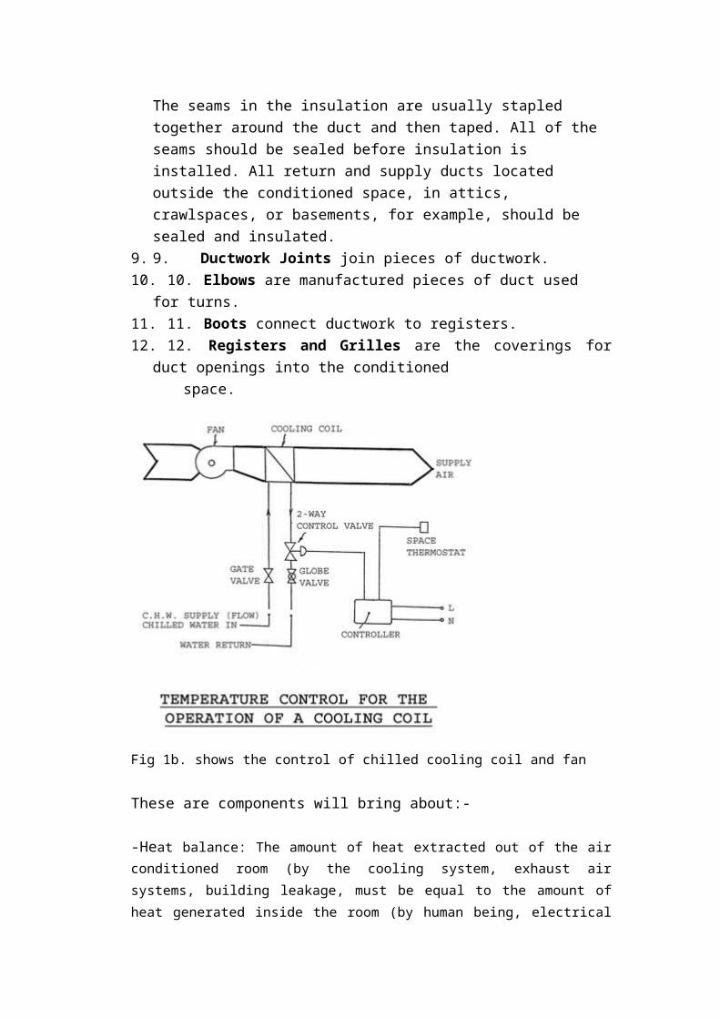
Fig 1b. shows the control of chilled cooling coil and fan
These are components will bring about:-
-Heat balance: The amount of heat extracted out of the air conditioned room (by the
cooling system, exhaust air systems, building leakage, must be equal to the amount of
heat generated inside the room (by human being, electrical appliances, etc.) and
transferred into the room (by conduction through the building envelope, radiation via the
glass, hot air leakage into the room through gaps in windows, doors, fresh air introduced
into the room, etc.) i.e. Total kW going into room = Total kW going out of the room.
-Air balance: The mass flow rate of the air going into the room = The mass flow rate of
air going out of the room. Fresh air coming into the room : 2.5 l/s per person, non-
smoking, 5 l/s per person for smoking accommodation, good indoor air quality (IAQ) is
important.
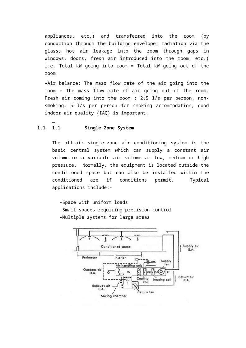
1.1 1.1 Single Zone System
The all-air single-zone air conditioning system is the basic central system which can
supply a constant air volume or a variable air volume at low, medium or high
pressure. Normally, the equipment is located outside the conditioned space but can
also be installed within the conditioned are if conditions permit. Typical applications
include:-
-Space with uniform loads
-Small spaces requiring precision control
-Multiple systems for large areas
Fig 1.1
1.2 1.2 Reheat System
The reheat system is a modification of the single-zone system. It provides:-
-Zone or space control for areas of unequal loading.
-Heating or cooling of perimeter areas with different exposures.
-Close control for process or comfort applications. In the reheat system, heat is added
as a secondary process to either preconditioned primary air or recirculated room air.
The heating medium can be hot water, steam or electricity.
Advantages : Closely controls space conditions
Disadvantages : Expensive to operate
Fig 1.2
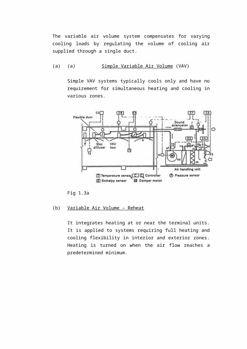
1.3 Variable Air Volume System
The variable air volume system compensates for varying cooling loads by regulating
the volume of cooling air supplied through a single duct.
(a) (a) Simple Variable Air Volume (VAV)
Simple VAV systems typically cools only and have no requirement for
simultaneous heating and cooling in various zones.
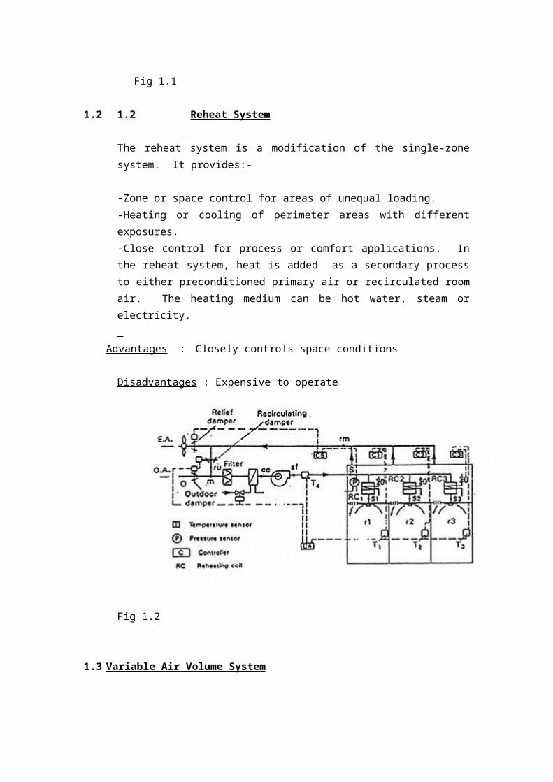
Fig 1.3a
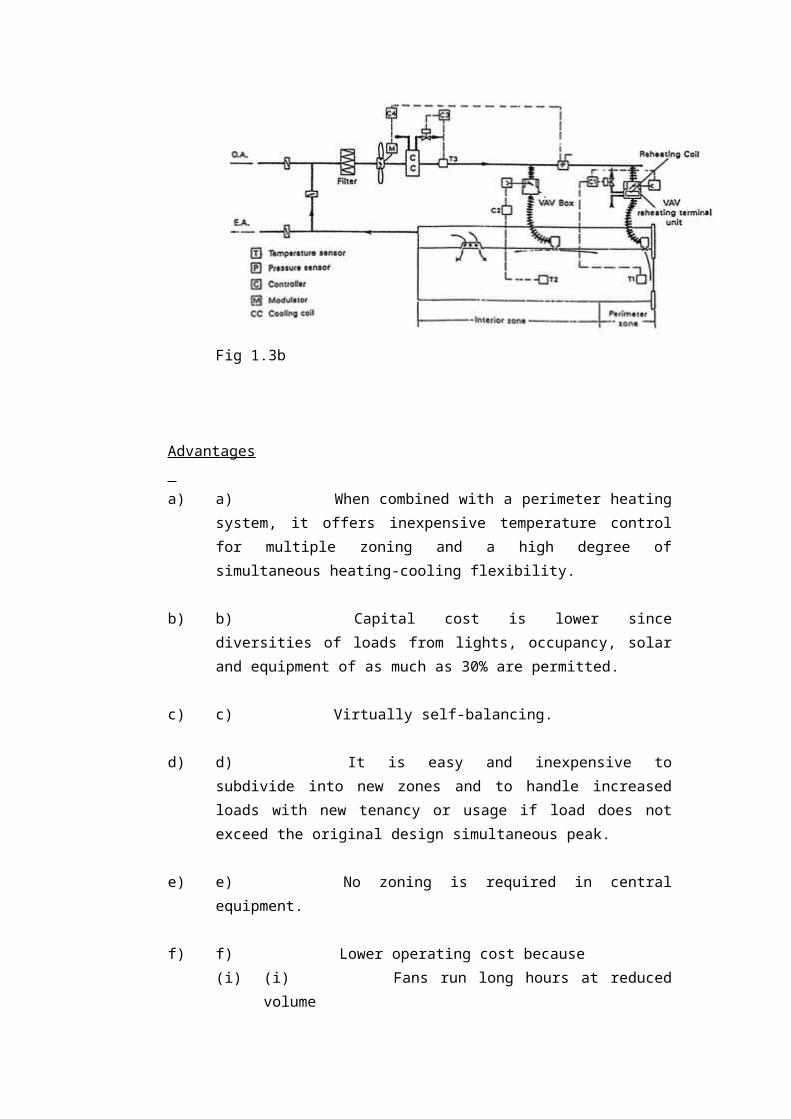
(b) Variable Air Volume – Reheat
It integrates heating at or near the terminal units. It is applied to systems
requiring full heating and cooling flexibility in interior and exterior zones.
Heating is turned on when the air flow reaches a predetermined minimum.
Fig 1.3b
Advantages
a) a) When combined with a perimeter heating system, it offers
inexpensive temperature control for multiple zoning and a high degree of
simultaneous heating-cooling flexibility.
b) b) Capital cost is lower since diversities of loads from lights,
occupancy, solar and equipment of as much as 30% are permitted.
c) c) Virtually self-balancing.
d) d) It is easy and inexpensive to subdivide into new zones and to handle
increased loads with new tenancy or usage if load does not exceed the
original design simultaneous peak.
e) e) No zoning is required in central equipment.
f) f) Lower operating cost because
(i) (i) Fans run long hours at reduced volume
(ii) (ii) Refrigeration, heating and pumping matches diversity of
loads
(iii) (iii) Unoccupied areas may be fully cut-off
b) g) Reduced noise level when the system is running at off-peak loads.
c) h) Allows simultaneous heating and cooling without seasonal
changeover.
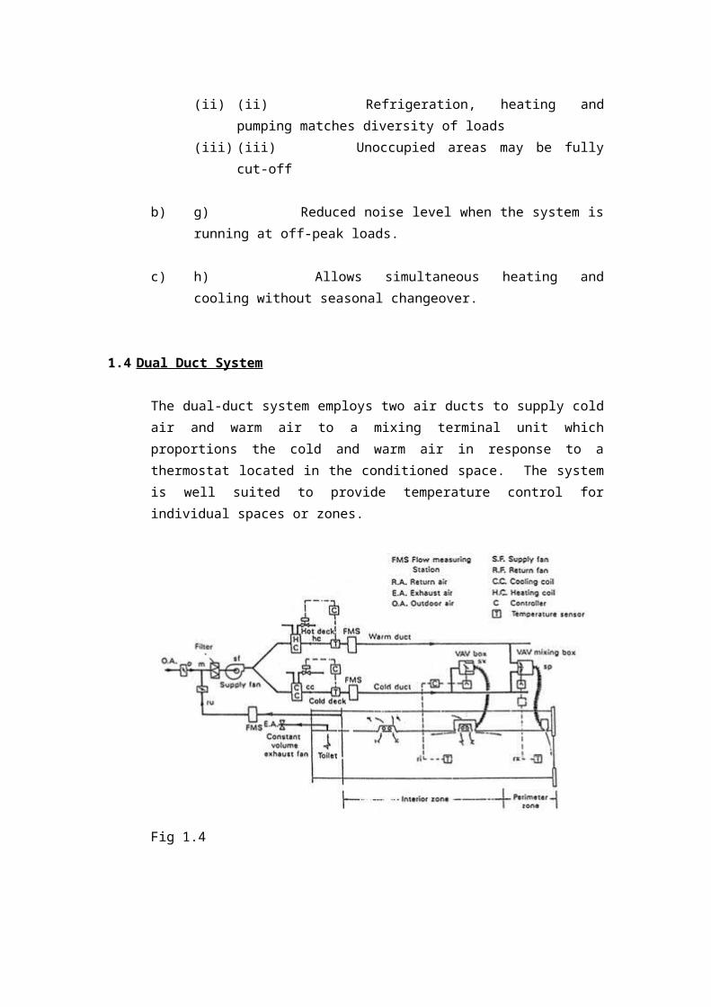
1.4 Dual Duct System
The dual-duct system employs two air ducts to supply cold air and warm air to a
mixing terminal unit which proportions the cold and warm air in response to a
thermostat located in the conditioned space. The system is well suited to provide
temperature control for individual spaces or zones.
Fig 1.4
Advantages (in addition to those common to all air systems)
1. 1. Systems with terminal volume regulation are self-balancing.
2. 2. Zoning of central equipment is not required.
3. 3. Instant temperature response is achieved because of simultaneous
availability of cold and warm air at each terminal unit.
4. 4. No seasonal changeover is necessary.
Disadvantages
1. 1. Initial cost is usually higher than other VAV systems.
2. 2. Does not operate as economically as other VAV systems.
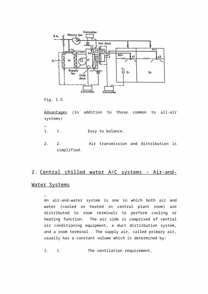
1.5 Multi-zone System
The multi-zone system applies to a relatively small number of zones served by a
single, central air-handling unit. Different zone requirements are met by mixing cold
and warm air through zone dampers at the central air handler in response to zone
thermostats.
Fig. 1.5
Advantages (in addition to those common to all-air systems)
1. 1. Easy to balance.
2. 2. Air transmission and distribution is simplified.
2. Central chilled water A/C systems - Air-and-Water Systems
An air-and-water system is one in which both air and water (cooled or heated in
central plant room) are distributed to room terminals to perform cooling or heating
function. The air side is comprised of central air conditioning equipment, a duct
distribution system, and a room terminal. The supply air, called primary air, usually
has a constant volume which is determined by:
1. 1. The ventilation requirement.
2. 2. The required sensible cooling capacity at maximum cooling load.
3. 3. The maximum sensible cooling capacity following changeover to
the winter cycle when chilled water is no longer circulated to the room
terminal.
The water side consists of a pump and piping to convey water to heat transfer
surfaces within each conditioned space. The water is commonly cooled by the
introduction of chilled water from the primary cooling system and is refereed to as
the secondary water loop. Individual room temperature control is by regulation of
either the water flow through it or the air flow over it.
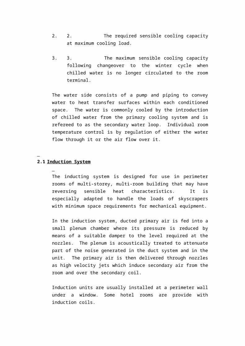
2.1 Induction System
The inducting system is designed for use in perimeter rooms of multi-storey, multi-
room building that may have reversing sensible heat characteristics. It is especially
adapted to handle the loads of skyscrapers with minimum space requirements for
mechanical equipment.
In the induction system, ducted primary air is fed into a small plenum chamber where
its pressure is reduced by means of a suitable damper to the level required at the
nozzles. The plenum is acoustically treated to attenuate part of the noise generated in
the duct system and in the unit. The primary air is then delivered through nozzles as
high velocity jets which induce secondary air from the room and over the secondary
coil.
Induction units are usually installed at a perimeter wall under a window. Some hotel
rooms are provide with induction coils.
Fig. 2.1
The induction system employs air ducts to convey treated air with higher pressure
levels and of the right adjustable quantities to various cooling/heating coil units.
These coil units are built in with induction nozzles such that when high pressure air
goes through them, air room the room is inducted across the fin surface of the water-
circulated coils. This inducted air stream is either cooled or heated after passing
through the coil, and then mixed with the air coming out of the nozzle. The right
quantity of high pressure air is adjusted automatically in response to a thermostat
located in the conditioned space. The system is well suited to provide temperature
control for individual spaces or zones.
Advantages
1. 1. Individual room temperature control.
2. 2. Separate sources of heating and cooling for each space available as
needed to satisfy a wide range of load variations.
3. 3. Low distribution system space required as a result of reducing the
air supply by use of secondary water for cooling and high velocity air design.
4. 4. Reduced size of central air handling equipment.
5. 5. Dehumidification & filtration performed in a central plant room
remote from conditioned space.
6. 6. Outdoor air supply is positive.
7. 7. Minimal maintenance required for individual induction units which
have no moving parts, i.e. no fans
8. 8. Air duct dimensions are smaller than VAV systems or CAV systems
9. 9. Zoning of central equipment is not required.
10. 10. No fan comes together with the coil, making the conditioned space
quiet.
Disadvantages
1. 1. Limited to perimeter space.
2. 2. The primary air supply is usually constant with no provision for
shutoff.
3. 3. Not applicable to spaces with high exhaust requirement.
4. 4. Higher energy consumption due to increased power required by the
primary pressure drop in the terminal units.
5. 5. Controls tend to be more complex than for all-air systems.
6. 6. A low chilled water temperature is needed to control space humidity
adequately.
7. 7. Seasonal changeover is necessary.
8. 8. Initial cost is usually higher than fan coil systems.
2.2 Fan-Coil System
The fan-coil system is similar to the inducting system, with the induction unit
replaced by the fan-coil unit. The basic elements of the fan-coil units are a finned-
tube coil and a fan section. The fan section recirculates air continuously from within
the perimeter space through the coil which is supplied with either hot or chilled water.
Auxiliary air may be delivered to the conditioned space for dehumidification and
ventilation purposes.
Fig 2.2a
Fig 2.2b
Advantages (in addition to those for induction units)
1. 1. System can be operated with the primary air turned off.
2. 2. The air velocity is fairly constant regardless of the primary air
quantity.
3. 3. Primary air can either connect directly to fan-coil unit or supply the
room separately.
Case studies See http://ug.arch.hku.hk/course/intgtech3/grad_hs/pt1/HVAC/index.html ;
http://ug.arch.hku.hk/course/intgtech3/grad_hs/pt2/computer/air.html ;
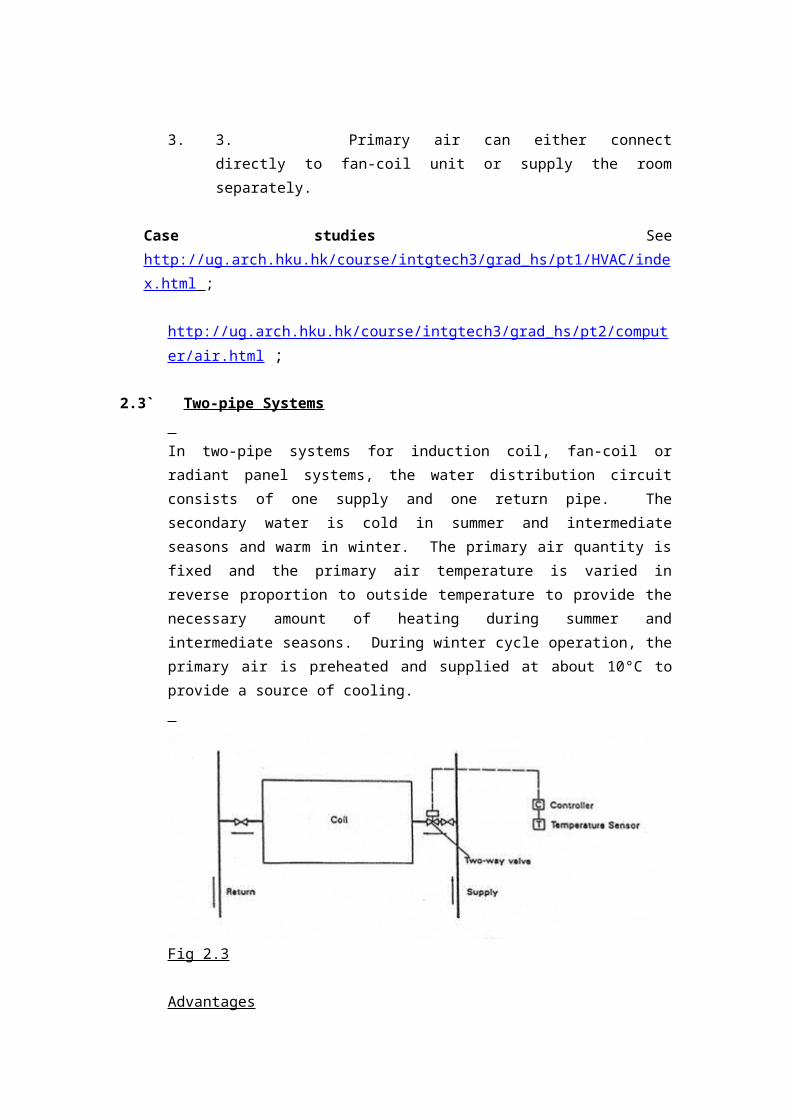
2.3` Two-pipe Systems
In two-pipe systems for induction coil, fan-coil or radiant panel systems, the water
distribution circuit consists of one supply and one return pipe. The secondary water
is cold in summer and intermediate seasons and warm in winter. The primary air
quantity is fixed and the primary air temperature is varied in reverse proportion to

outside temperature to provide the necessary amount of heating during summer and
intermediate seasons. During winter cycle operation, the primary air is preheated and
supplied at about 10°C to provide a source of cooling.
Fig 2.3
Advantages
1. 1. Usually less expensive to install than four pipe systems.
Disadvantages
1. 1. Less capable of handling widely varying loads or providing widely
varying choice of room temperature than four-pipe systems.
2. 2. Cumbersome to change over.
3. 3. More costly to operate than four-pipe systems.
2.4 ` Three-pipe Systems
Three-pipe systems for induction coil, fan-coil and radiant panel systems have three
pipes to each terminal unit, a cold water pipe, a warm water pipe and a common
return. These systems are rarely used today because they consume excess energy.
Fig 2.4
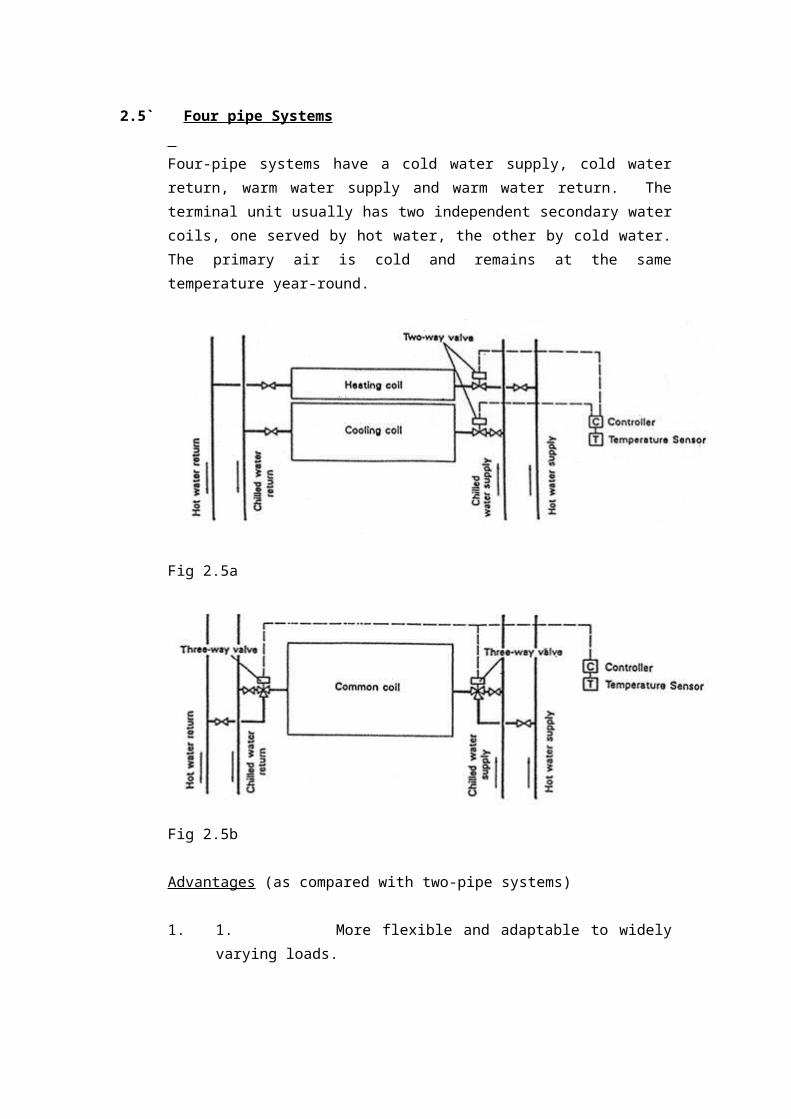
2.5` Four pipe Systems
Four-pipe systems have a cold water supply, cold water return, warm water supply
and warm water return. The terminal unit usually has two independent secondary
water coils, one served by hot water, the other by cold water. The primary air is cold
and remains at the same temperature year-round.
Fig 2.5a
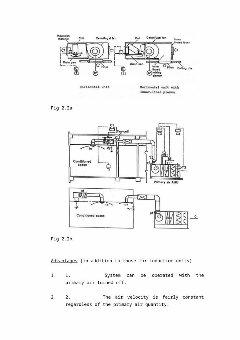
Fig 2.5b
Advantages (as compared with two-pipe systems)
1. 1. More flexible and adaptable to widely varying loads.
2. 2. Simpler to operate (No summer-winter changeover and primary air
reheat schedule).
3. 3. Higher efficiency due to lower operating costs.
Disadvantages
1. 1. Higher initial cost.
3. Central chilled water air conditioning systems - All-water Systems
All-water systems are those with fan-coil, unit ventilator, or valance type room
terminals with unconditioned ventilation air supplied by an opening through the wall
or by infiltration. Cooling and dehumidification is provided by circulating chilled
water through a finned coil in the unit. Heating is provided by supplying hot water
through the same or a separate coil.
System Advantages
1. 1. Flexible and readily adaptable to many building module
requirements.
2. 2. Provides individual room control.
System Disadvantages
1. 1. No positive ventilation is provided unless wall openings are used.
2. 2. No humidification is provided.
3. 3. Seasonal change over is required.
4. 4. Maintenance and service work has to be done in the occupied areas.
3.1 Fan-coil units
A fan-coil unit basically consists of a finned tube coil, a filter and a fan section. The
fan recirculates air continuously from the space through the coil, which contains
either hot or chilled water.
Fig 3.1a
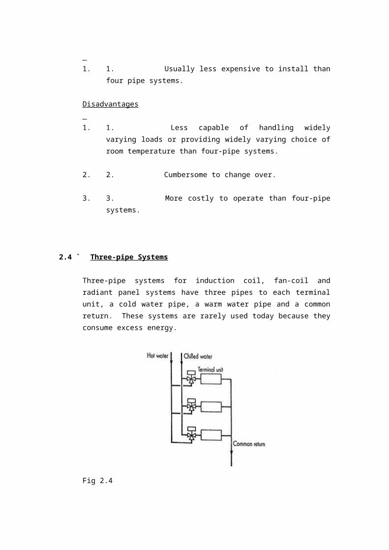
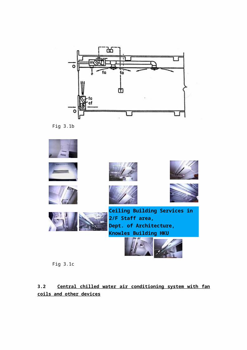
Fig 3.1b
Ceiling Building Services in 2/F
Staff area,
Dept. of Architecture, Knowles
Building HKU
Fig 3.1c
3.2 Central chilled water air conditioning system with fan coils and other devices
In this system, the following circuits do not mix with each other, and heat exchange is
performed via various metal surfaces:-
-the chilled water circuit – nominally 12 deg .C entering water chiller, 7 deg. C
leaving chiller, i.e. nominally 7 deg .C entering fan coil units [FCU] /air handling
unit[AHU] /primary handling unit[PAU]- for treating fresh air, 12 deg. C leaving
these devices – chilled water pumps move water through this circuit – CH. W. F-
chilled water flow ;
- CH. W. R- chilled water flow return.
-refrigerant circuit – refrigerant compressors move the refrigerant through this circuit
-cooling water circuit - nominally 35 deg .C entering water cooling tower , 30 deg. C
leaving cooling tower, i.e. nominally 30 deg .C entering condenser of chiller
assembly, 35 deg. C leaving condenser of chiller assembly – Condenser water pumps
move condenser water through this circuit. See attached diagram and See
http://www.ekingair.com/Screw.files/frame.htm
3.2 Water cooling tower
A water cooling tower cools the water entering it from 35 deg. C to 30 deg. C
nominally. The warmer water is sprayed inside the cooling tower admidst the stream
of an upward air flow produced by the fan at the top of the tower. The air stream
going out carries water particles. These water particles should not be taken into
buildings, to avoid Legionnaire disease to occur. Condenser water pumps move
condenser water through this circuit. Water in this circuit has to be treated. There is
water loss to atmosphere in using cooling towers. For cooling towers, see
http://www.engnet.com.tw/lc/A2.HTM , and http://www.engnet.com.tw/lc/LRC-
SAS.HTM
4. Direct expansion Systems
[i.e. direct expansion of refrigerant, without the chilled water cooling medium ]
4.1 Direct expansion Systems [i.e. direct expansion of refrigerant , without the chilled
water cooling medium ] -Window Air Conditioners
A window unit is an encased assembly designed primarily for mounting in a window,
through a wall, or as a console. These units are designed for comfort cooling and to
provide delivery of conditioned air to a room either without ducts or with very short
ducts. They include a prime source of refrigeration, dehumidification, means for
circulating and cleaning air, and may also include means for ventilating, and/or
exhausting and heating.
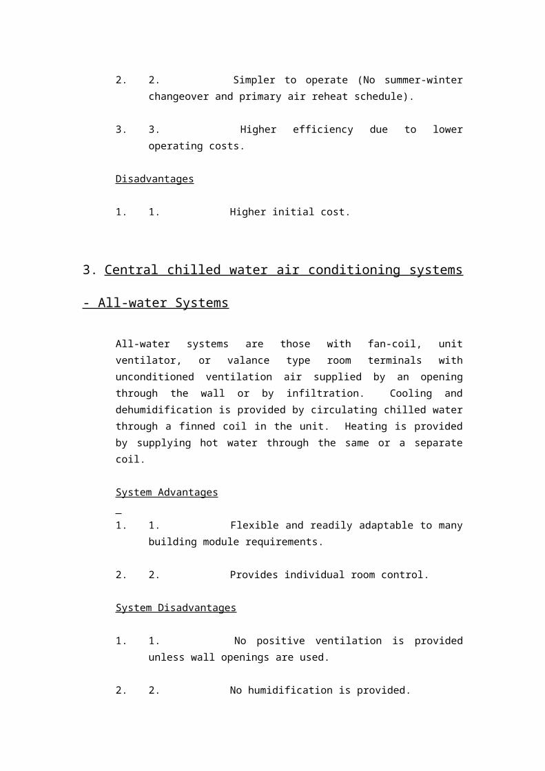
Fig 4.1a
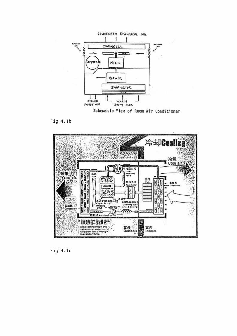
Fig 4.1b
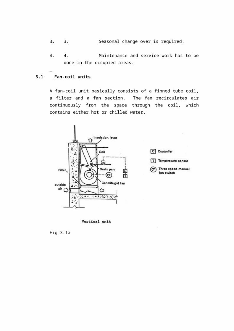
Fig 4.1c
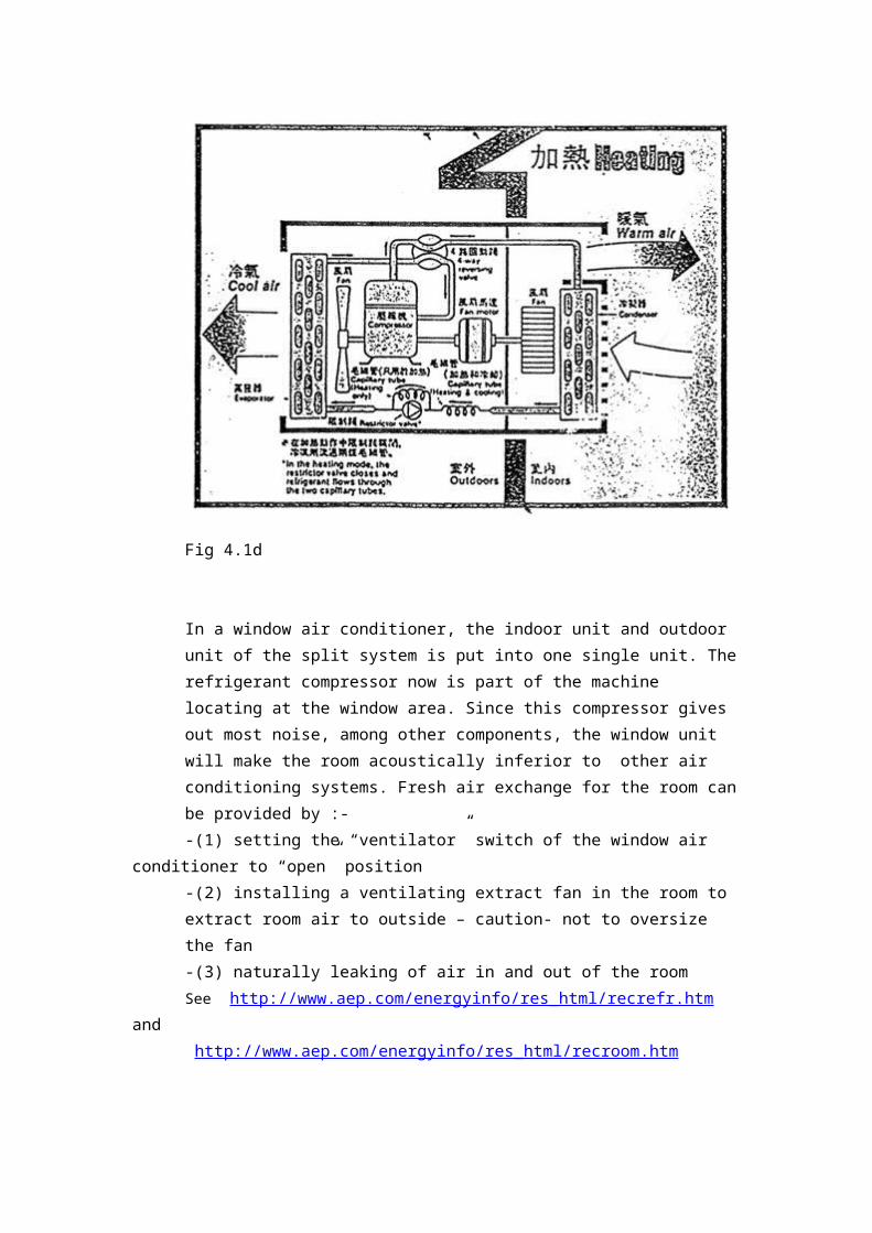
Fig 4.1d
In a window air conditioner, the indoor unit and outdoor unit of the split system is put
into one single unit. The refrigerant compressor now is part of the machine locating at
the window area. Since this compressor gives out most noise, among other
components, the window unit will make the room acoustically inferior to other air
conditioning systems. Fresh air exchange for the room can be provided by :-
-(1) setting the “ventilator” switch of the window air conditioner to “open” position
-(2) installing a ventilating extract fan in the room to extract room air to outside –
caution- not to oversize the fan
-(3) naturally leaking of air in and out of the room
See http://www.aep.com/energyinfo/res_html/recrefr.htm and
http://www.aep.com/energyinfo/res_html/recroom.htm
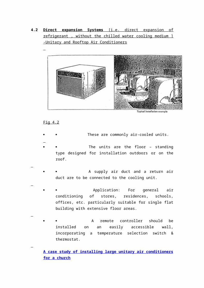
4.2 Direct expansion Systems [i.e. direct expansion of refrigerant , without the chilled
water cooling medium ] -Unitary and Rooftop Air Conditioners
Fig 4.2
These are commonly air-cooled units.
The units are the floor – standing type designed for installation
outdoors or on the roof.
A supply air duct and a return air duct are to be connected to the
cooling unit.
Application: For general air conditioning of stores, residences,
schools, offices, etc. particularly suitable for single flat building with
extensive floor areas.
A remote controller should be installed on an easily accessible wall,
incorporating a temperature selection switch & thermostat.
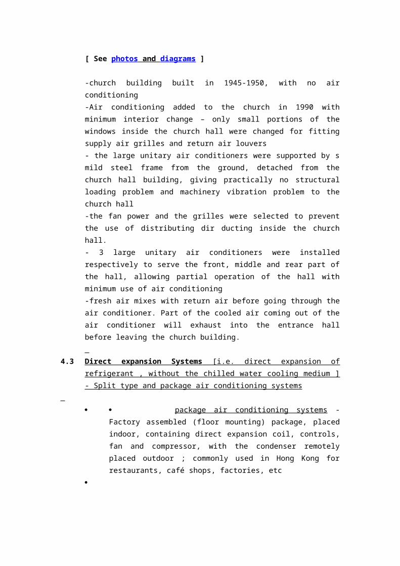
A case study of installing large unitary air conditioners for a church
[ See photos and diagrams ]
-church building built in 1945-1950, with no air conditioning
-Air conditioning added to the church in 1990 with minimum interior change – only
small portions of the windows inside the church hall were changed for fitting supply
air grilles and return air louvers
- the large unitary air conditioners were supported by s mild steel frame from the
ground, detached from the church hall building, giving practically no structural
loading problem and machinery vibration problem to the church hall
-the fan power and the grilles were selected to prevent the use of distributing dir
ducting inside the church hall.
- 3 large unitary air conditioners were installed respectively to serve the front, middle
and rear part of the hall, allowing partial operation of the hall with minimum use of
air conditioning
-fresh air mixes with return air before going through the air conditioner. Part of the
cooled air coming out of the air conditioner will exhaust into the entrance hall before
leaving the church building.
4.3 Direct expansion Systems [i.e. direct expansion of refrigerant , without the chilled
water cooling medium ] - Split type and package air conditioning systems
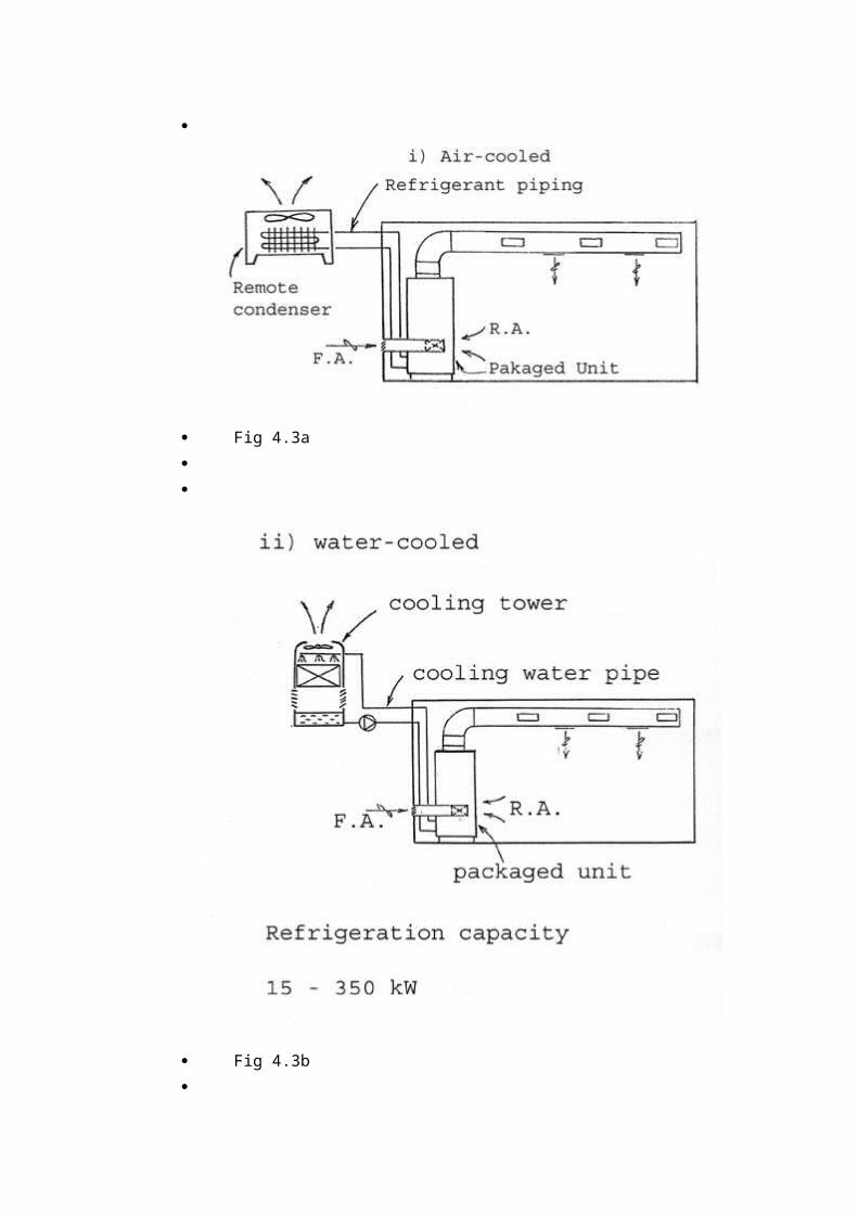
package air conditioning systems - Factory assembled (floor
mounting) package, placed indoor, containing direct expansion coil, controls,
fan and compressor, with the condenser remotely placed outdoor ; commonly
used in Hong Kong for restaurants, café shops, factories, etc
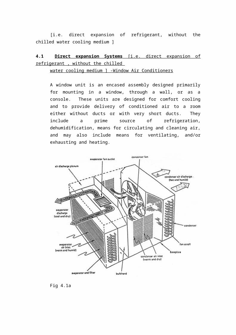
Fig 4.3a
Fig 4.3b
split air conditioning systems - Factory assembled (ceiling
mounting) indoor unit of fan and direct expansion coil, controls, with the
condensing unit [i.e. compressor and condensing coil ] remotely placed
outdoor ; commonly used in Hong Kong for café shops, small offices, some
domestic units, etc
Case study – see http://arch.hku.hk/teaching/project/project302.html
4.3.1. The basic concepts of a split air conditioning system [ Small system]
a. A split air conditioning system consists of an indoor unit and an outdoor unit
connected together by refrigerant pipes. The refrigerant circulates between these 2
units [i.e. 2 parts of the system] to take heat from indoor to outdoor, by firstly having
heat of the room air absorbed into the refrigerant via an air-refrigerant heat exchanger
which is the indoor unit, then conveying the heat to the outdoor unit for disposal. See
http://www.aep.com/energyinfo/res_html/reccent.htm
b. The indoor unit comprises a finned coil and a fan which is driven by an electric
motor. Refrigerant is circulated inside the finned coil to the outside unit and then back
to the indoor unit. The fan pulls or pushes air around the outer surfaces of the coil
inside the indoor unit, taking warm air from the room and injecting cooled air into the
room in summer. The refrigerant has no direct contact with air. So the heat of the
room air is transferred into the refrigerant in the indoor unit. Inside the coil,
refrigerant evaporates, and the indoor unit is therefore commonly called an
evaporator by the engineers. The indoor unit is wall-mount or ceiling mount unit.
See http://www.daikin.be/home.nsf/fFRM?ReadForm
c. The outdoor unit
The refrigerant then takes the heat from the indoor unit to the outdoor unit, which is
commonly called a condensing unit. [ i.e. a unit for refrigerant to condense] In an
air-cooled outdoor unit, heat exchange occurs in the same way as the indoor unit.
However, the outdoor unit contains a refrigerant compressor, in addition to having a
finned coil and motor-driven fan. The refrigerant does not have direct contact with
air. Refrigerant going through this outdoor coil is losing its energy across the metal
surface of the coil to the atmosphere, as outside air is drawn pass the surface of the
finned coil by the fan. By passing through this finned coil, the outside air is heated
up, by normally about 5 deg. rise in temperature. The outside air passing through the
outdoor unit is an open circuit. That is, air path is not recirculated.
See http://www.daikin.be/home.nsf/fFRM?ReadForm
The refrigerant compressor, which usually is installed inside the outdoor unit, is
pumping the refrigerant through the indoor unit and the outdoor unit. [ In the
split system therefore the compressor – generating noise when pumping refrigerant-
is located outdoor , inside the outdoor unit] The refrigerant takes up energy as it
goes through the indoor unit, and rejects energy to the outside atmosphere as it
goes through the outdoor unit. Energy rejected is the sum of the energy taken
indoor plus the energy consumed by the compressor in pumping the refrigerant
through the refrigerant circuit. This refrigerant circuit is a closed circuit, and if
pipe joints are well installed , no leakage of refrigerant should occur.
d. Air circuits for the indoor environment. The air passing through the indoor unit
is cooled, say to 15 deg. C, before recirculated back to the room. A large part of air
heated up in the room, say to 25 deg. [ Note : Design room temperature is 23 deg C
in general for human comfort ] then goes back to the indoor unit for cooling. A
small part of room air is extracted to outside by an exhaust fan, with an amount of
fresh outside air coming in to replenish this amount exhausted. Now this make up air
can be supplied by connecting a small air duct from an external opening to the indoor
unit. See diagram attached
e. Single splits and multiple splits
-single split – one indoor unit is connected to one outdoor unit by insulated copper
refrigerant pipes
-multiple splits– several indoor units are connected to one outdoor unit by insulated
copper refrigerant pipes
See http://www.daikin.be/home.nsf/fFRM?ReadForm
See also http://www.ambthair.com/multisplit.html for a design guide
f. Energy saving options
If heat rejection in the outdoor unit is taken care by cooling water , there would be a
saving of 30% of energy. In urban areas,. cooling water can be provided by fresh
water cooling towers. The water cooling tower can be placed at the top of a building,
with a pump drawing water from it to circulate the condensing water to the outdoor
units of the split system. After taking up heat from the outdoor unit, with an increase
of unusually 5 deg. C, condensing water is circulated back to the cooling tower for
cooling again. Of course the finned coil f the outdoor unit has to be replaced by a
water –cooled condenser. See “water cooling tower” below.
Another efficient option is to have a few additional valves and controls added to the
basic split system to make it to serve as a heat pump system in winter. That is, the
refrigerant will do a reverse job in taking heat from outside , and rejecting it to the
indoor environment. Thus the refrigerant goes through a reversed cycle by taking heat
from outside and rejecting heat to the room. One unit of energy for pumping the
refrigerant will cause 4 units of energy to be taken from outside, i.e. ,totally 5 units of
energy, into the room. For heat pumps, see
http://www.spec-net.com.au/hitachi/reverse1.htm,
http://www.nrc.ca/irc/cbd/cbd195e.html , http://www.heatpumpcentre.org/tutorial ,
http://www.iaheatpump.org/winter.html ,
http://www.heatpumpcentre.org/tutorial/buildings.htm ,
g. A variant of split air conditioning system - A packaged system
If the refrigerant compressor of the outdoor unit of the split air conditioning system is
installed together with the indoor unit, it is called a packaged system. The
compressor now is put indoor, making the machine less quite than the split system.
However this will allow a larger cooling capacity for the indoor unit, which then will
be floor-mount usually. A packaged system is needed if the outdoor unit, now called
a condenser, is put on the roof top, with the indoor unit a few floors below.
h. Direct expansion air conditioning equipments consist of factory-matched
refrigeration cycle components for inclusion is air-conditioning systems which are
field designed to meet the needs of the user. The following list of variations is
indicative of the vast number of types of unitary air conditioners presently available.
1. 1. Arrangement: single or split.
2. 2. Heat rejection: air-cooled, evaporative condenser, water-cooled.
3. 3. Unit exterior: decorative for in-space
applications, functional for equipment room and ducts,
weatherproofed for outdoors.
4. 4. Placement: floor standing, wall-mounted, ceiling
suspended, roof-mounted.
5. 5. Indoor air: vertical upflow, counterflow,
horizontal, 90° and 180° degree turns, with fan, or for use
with forced air furnace.
6. 6. Locations: Indoor - Exposed with plenums or
furred in ductwork; concealed in closets, attic, crawl spaces,
basements, garages or equipment room.
Wall - Built-in, window, transom.
Outdoor -Rooftop, wall-mounted or on ground.
4.4 Heat Pumps
The term ‘heat pump’, as applied to a year-round air conditioning system, commonly
denotes a system in which refrigeration equipment is used in such a manner that heat
is taken from a heat source and given up to the conditioned space when heating
service is wanted, and is removed from the space and discharged to a heat sink when
cooling and dehumidification are desired.
Heat pumps for air conditioning service may be classified according to
a) a) type of heat source and sink.
b) b) Heating and cooling distribution fluid.
c) c) Type of thermodynamic cycle.
d) d) Type of building structure.
e) e) Size and configuration.
4.3.1 Air-to-Air Heat Pumps
The air-to-air heat pump is the most common type of heat pumps. It is particularly
suitable for factory-built unitary heat pumps, and has been widely used for residential
and commercial application. Air is used as the heat source and heat sink. Extended
surface, forced convection heat transfer coils are normally employed to transfer the
heat between the air and the refrigerant. When selecting or designing an air-source
heat pup, two factors in particular must be taken into consideration:
1) 1) the variation in temperature experienced in a given locality.
2) 2) the formation of frost.
4.3.2 Water-source Heat Pumps
The water-source heat pump uses water and air as the heat source or heat sink
depending on the mode of operation. When cooling, water is used as the heat sink,
and the heat pump operates as a water-cooled air conditioner. When heating, water is
used as the heat source and the equipment operates as a water chiller.
The water-source heat pump is suitable for many types of multi-room buildings,
including office buildings, hotels, schools, apartment buildings, manufacturing
facilities and hospitals.
Advantages
1. 1. Affords opportunity for energy conservation by recovering heat
from interior zones and/or waste heat and by storing excess heat from
daytime cooling for night time heating.
2. 2. No wall openings required.
3. 3. Longer expected life than air-cooled heat pumps.
4. 4. Lower noise level because condenser fans are eliminated.
5. 5. Energy for the heat pumps can be metered directly to each tenant.
6. 6. Total life cycle cost frequently compares favourably to central
systems when considering relative installed cost, operating costs, and system
life.
Disadvantages
1. 1. Space required for boiler, heat exchanger, pumps and heat rejector.
2. 2. Higher initial cost than for most other multiple-packaged unit
systems.
3. 3. Reduced air flow can cause the heat pump to cycle cutout. Good
filter maintenance is imperative.