Embed Size (px)
Citation preview
Natural Comfort for Everybody
AIR CONDITIONING SYSTEMS

COMFORTTAKES ON NEW MEANINGWITH THE POWER OFTECHNOLOGY
NEW REFRIGERANT
Our technologically advancedMr. Slim Power Inverter systemsimprove comfort, operate withsignificantly less noise,.... and provide increased energy savings.
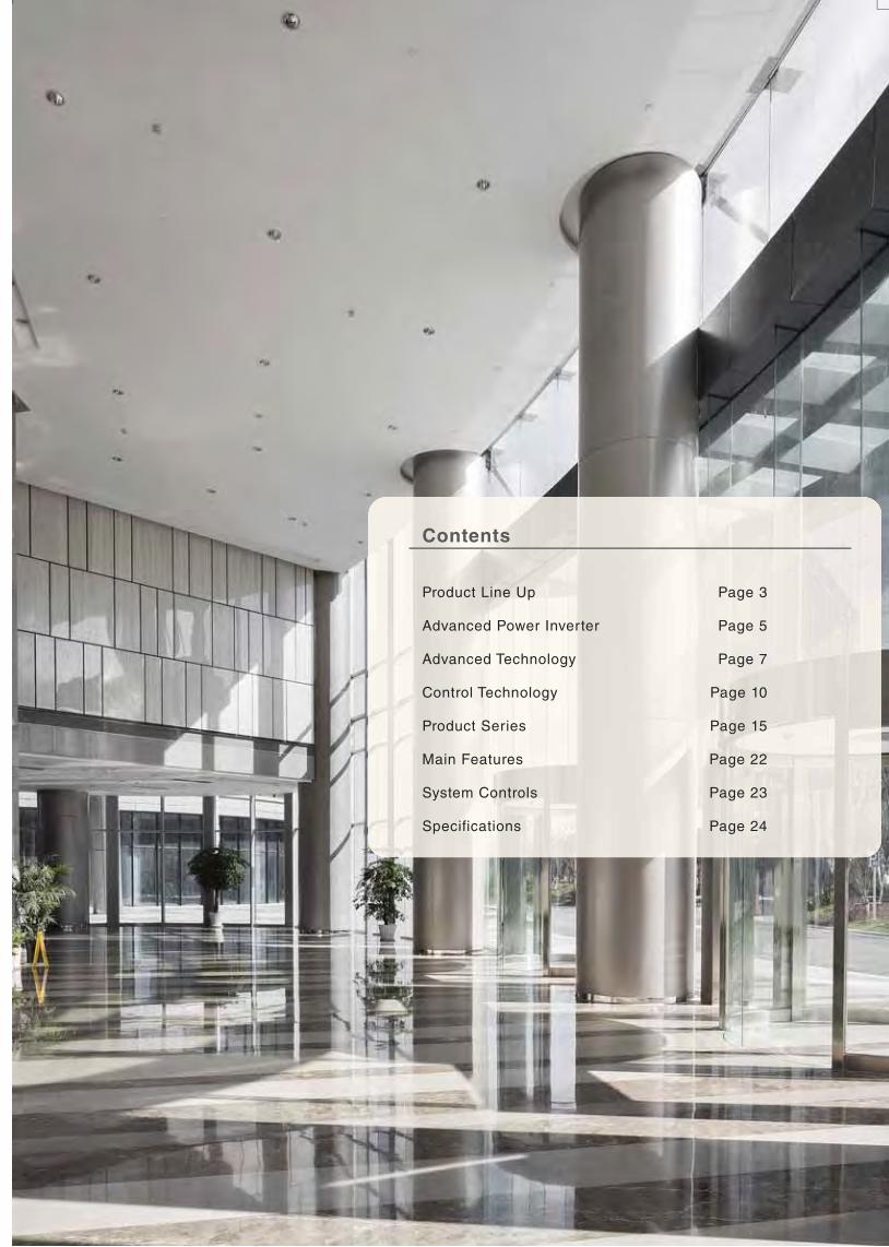
Product Line Up Page 3
Advanced Power Inverter Page 5
Advanced Technology Page 7
Control Technology Page 10
Product Series Page 15
Main Features Page 22
System Controls Page 23
Specifications Page 24
Contents
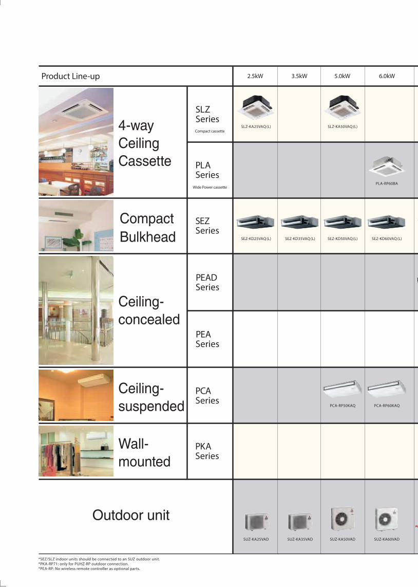
PEADSeries
PEASeries
PCASeries
PKASeries
PLASeries
Compact cassette
Wide Power cassette
SLZSeries
SEZSeries
Outdoor unit
Product Line-up 3.5kW
SUZ-KA35VAD
SEZ-KD35VAQ (L)
2.5kW
SLZ-KA25VAQ (L)
SUZ-KA25VAD
SEZ-KD25VAQ (L)
*SEZ/SLZ indoor units should be connected to an SUZ outdoor unit.*PKA-RP71: only for PUHZ-RP outdoor connection.*PEA-RP: No wireless remote controller as optional parts.
5.0kW
SUZ-KA50VAD
SLZ-KA50VAQ (L)
SEZ-KD50VAQ (L)
PCA-RP50KAQ
6.0kW
SUZ-KA60VAD
PLA-RP60BA
SEZ-KD60VAQ (L)
PCA-RP60KAQ
4-wayCeilingCassette
Ceiling-concealed
Ceiling-suspended
Wall-mounted
CompactBulkhead
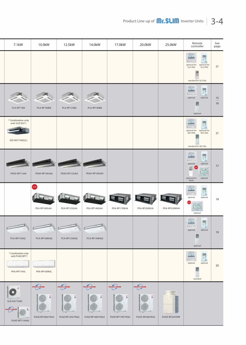
Product Line-up of Inverter Units 3-4
25.0kW
21
21
20
17.0kW
PUHZ-RP170V/YKA2
20.0kW
PUHZ-RP200YKA2 PUHZ-RP250YKM
Remotecontroller
Seepage
15
16
19
standard for SLZ-VAL
optional forSLZ-VAQ
optional forSLZ-VAQ
17
18
14.0kW
PEA-RP140GAA
PEAD-RP140JAA
PEA-RP250WHA
PLA-RP140BA
PUHZ-RP140V/YKA2
PEA-RP125GAAPEA-RP100GAA
NEW
NEW
NEW
PCA-RP140KAQ
12.5kW
PEAD-RP125JAA
PLA-RP125BA
PUHZ-RP125V/YKA2
PCA-RP125KAQ
10.0kW
PKA-RP100KAL
PUHZ-RP100V/YKA2
PEAD-RP100JAA
PLA-RP100BA
PCA-RP100KAQ
7.1kW
PEAD-RP71JAA
PKA-RP71KAL
SEZ-KD71VAQ (L)
* Combination onlywith SUZ-KA71
PLA-RP71BA
PUHZ-RP71VHA5
SUZ-KA71VAD
PCA-RP71KAQ
* Combination only with PUHZ-RP71
optional
optionaloptional
standard for SEZ-VAL
optional forSEZ-VAQ
optional forSEZ-VAQ
optional
optional
optional
optionaloptional
optional
optionaloptional
standard
optionaloptional
optional forPEAD
optional
PEA-RP200WJAPEA-RP170WJA
Outdoor unit
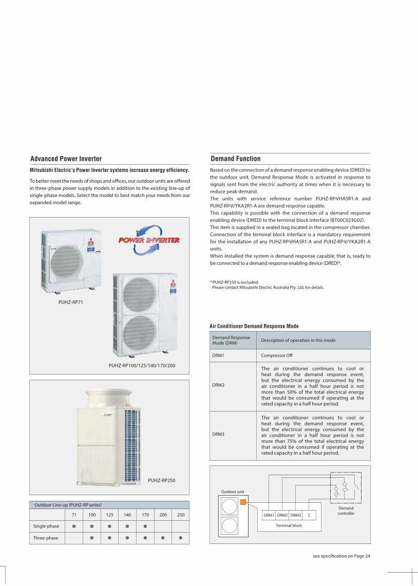
Based on the connection of a demand response enabling device (DRED) to the outdoor unit, Demand Response Mode is activated in response to signals sent from the electric authority at times when it is necessary to reduce peak demand. The units with service reference number PUHZ-RP•VHA5R1-A and PUHZ-RP•V/YKA2R1-A are demand response capable.This capability is possible with the connection of a demand response enabling device (DRED) to the terminal block interface (BT00C023G02).This item is supplied in a sealed bag located in the compressor chamber. Connection of the terminal block interface is a mandatory requirement for the installation of any PUHZ-RP•VHA5R1-A and PUHZ-RP•V/YKA2R1-A units.When installed the system is demand response capable; that is, ready to be connected to a demand response enabling device (DRED)*.
Mitsubishi Electric’s Power Inverter systems increase energy efficiency.
To better meet the needs of shops and offices, our outdoor units are offered in three-phase power supply models in addition to the existing line-up of single-phase models. Select the model to best match your needs from our expanded model range.
DRM1 Compressor Off
DRM2
Demand ResponseMode (DRM) Description of operation in this mode
Advanced Power Inverter Demand Function
Three-phase
Outdoor Line-up (PUHZ-RP series)
Single-phase
71 100 125 140 170 200 250
The air conditioner continues to cool orheat during the demand response event,but the electrical energy consumed by theair conditioner in a half hour period is notmore than 50% of the total electrical energythat would be consumed if operating at therated capacity in a half hour period.
DRM3
The air conditioner continues to cool orheat during the demand response event,but the electrical energy consumed by theair conditioner in a half hour period is notmore than 75% of the total electrical energythat would be consumed if operating at therated capacity in a half hour period.
Air Conditioner Demand Response Mode
Demandcontroller
Terminal block
DRM1 DRM2 DRM3 C
*PUHZ-RP250 is excluded.Please contact Mitsubishi Electric Australia Pty. Ltd. for details.
see specification on Page 24
PUHZ-RP100/125/140/170/200
PUHZ-RP250
PUHZ-RP71
Advanced Power Inverter 05-06
see specification on Page 24
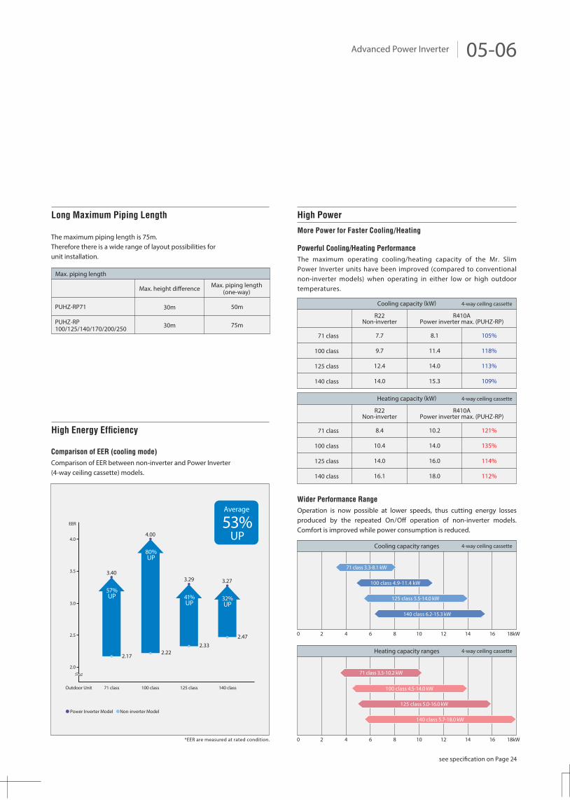
Wider Performance Range
Operation is now possible at lower speeds, thus cutting energy losses produced by the repeated On/Off operation of non-inverter models. Comfort is improved while power consumption is reduced.
The maximum piping length is 75m.Therefore there is a wide range of layout possibilities forunit installation.
PUHZ-RP71
PUHZ-RP100/125/140/170/200/250
Max. height difference Max. piping length(one-way)
30m
30m
50m
75m
Max. piping length
Cooling capacity (kW)
0 2 4 6 8 10 12 14 16 18kW
4-way ceiling cassette
High Power
More Power for Faster Cooling/Heating
Powerful Cooling/Heating Performance
The maximum operating cooling/heating capacity of the Mr. Slim Power Inverter units have been improved (compared to conventional non-inverter models) when operating in either low or high outdoor temperatures.
71 class
100 class
125 class
140 class
7.7
9.7
12.4
14.0
8.1
11.4
14.0
15.3
105%
118%
113%
109%
R22Non-inverter
R410APower inverter max. (PUHZ-RP)
4-way ceiling cassetteHeating capacity (kW)
4-way ceiling cassette
71 class
100 class
125 class
140 class
8.4
10.4
14.0
16.1
10.2
14.0
16.0
18.0
121%
135%
114%
112%
R22Non-inverter
R410APower inverter max. (PUHZ-RP)
Cooling capacity ranges
71 class 3.3-8.1 kW
100 class 4.9-11.4 kW
125 class 5.5-14.0 kW
140 class 6.2-15.3 kW
0 2 4 6 8 10 12 14 16 18kW
4-way ceiling cassetteHeating capacity ranges
71 class 3.5-10.2 kW
100 class 4.5-14.0 kW
125 class 5.0-16.0 kW
140 class 5.7-18.0 kW
Long Maximum Piping Length
41%UP
32%UP
57%UP
80%UP
Comparison of EER (cooling mode)
Comparison of EER between non-inverter and Power Inverter (4-way ceiling cassette) models.
Power Inverter Model Non-inverter Model
EER
Outdoor Unit
4.0
3.5
3.0
2.5
2.0
71 class 100 class 125 class 140 class
2.47
3.27
2.22
4.00
2.33
3.29
2.17
3.40
Average
53%UP
High Energy Efficiency
*EER are measured at rated condition.
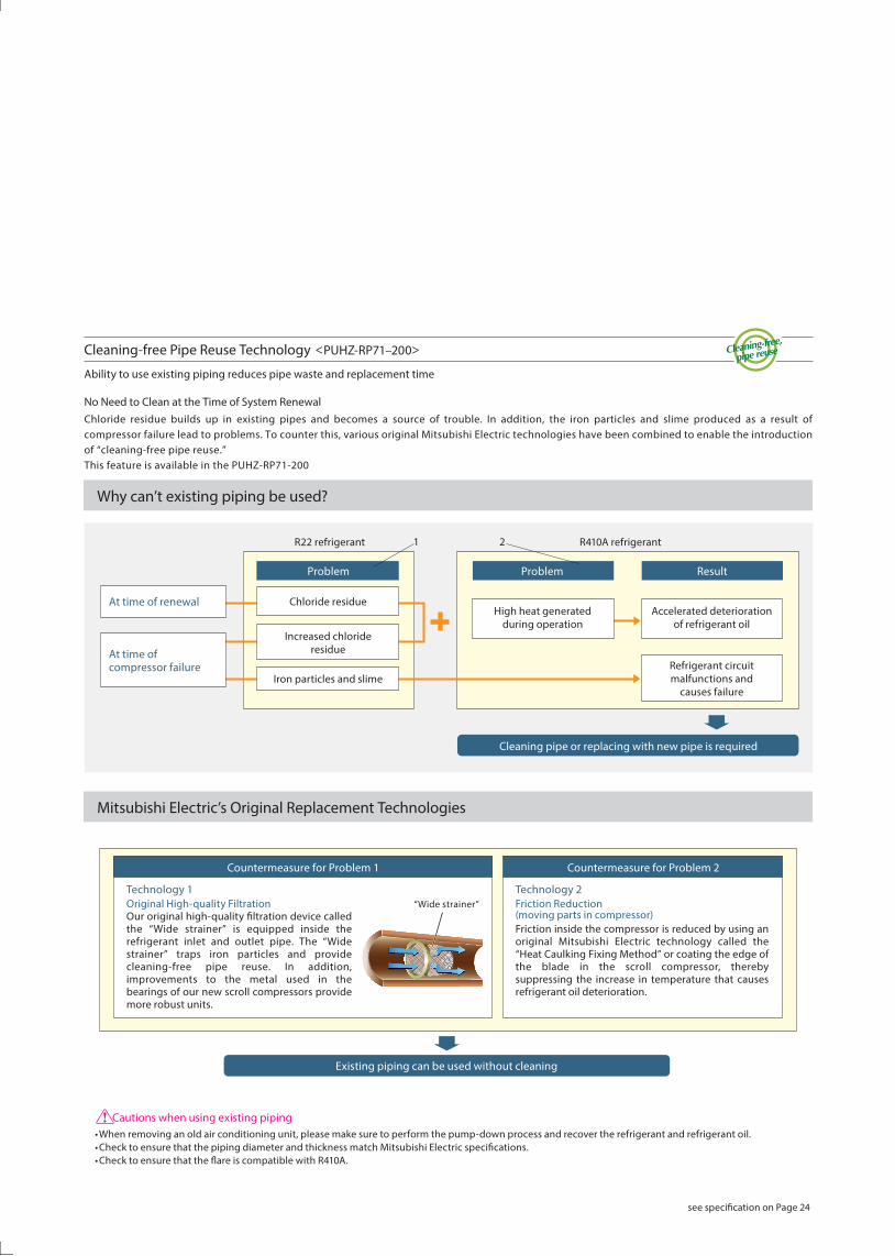
Cleaning-free Pipe Reuse Technology <PUHZ-RP71–200>
Ability to use existing piping reduces pipe waste and replacement time
No Need to Clean at the Time of System RenewalChloride residue builds up in existing pipes and becomes a source of trouble. In addition, the iron particles and slime produced as a result of compressor failure lead to problems. To counter this, various original Mitsubishi Electric technologies have been combined to enable the introduction of “cleaning-free pipe reuse.” This feature is available in the PUHZ-RP71-200
Cautions when using existing piping•When removing an old air conditioning unit, please make sure to perform the pump-down process and recover the refrigerant and refrigerant oil.•Check to ensure that the piping diameter and thickness match Mitsubishi Electric specifications.•Check to ensure that the flare is compatible with R410A.
Cleaning pipe or replacing with new pipe is required
Result
R22 refrigerant R410A refrigerant
Accelerated deteriorationof refrigerant oil
Problem
High heat generatedduring operation
Problem
Chloride residue
Increased chlorideresidue
Iron particles and slimeRefrigerant circuitmalfunctions and
causes failure
At time of renewal
At time ofcompressor failure
Countermeasure for Problem 1 Countermeasure for Problem 2
Technology 2Friction Reduction(moving parts in compressor)Friction inside the compressor is reduced by using an original Mitsubishi Electric technology called the “Heat Caulking Fixing Method” or coating the edge of the blade in the scroll compressor, thereby suppressing the increase in temperature that causes refrigerant oil deterioration.
Technology 1Original High-quality FiltrationOur original high-quality filtration device called the “Wide strainer” is equipped inside the refrigerant inlet and outlet pipe. The “Wide strainer” traps iron particles and provide cleaning-free pipe reuse. In addition, improvements to the metal used in the bearings of our new scroll compressors provide more robust units.
Existing piping can be used without cleaning
Why can’t existing piping be used?
Mitsubishi Electric’s Original Replacement Technologies
“Wide strainer”
1 2
see specification on Page 24
Advanced Technology 07-08
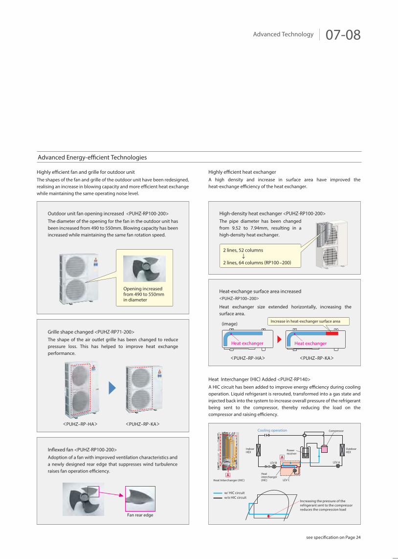
Advanced Energy-efficient Technologies
Highly efficient fan and grille for outdoor unitThe shapes of the fan and grille of the outdoor unit have been redesigned, realising an increase in blowing capacity and more efficient heat exchange while maintaining the same operating noise level.
Highly efficient heat exchangerA high density and increase in surface area have improved the heat-exchange efficiency of the heat exchanger.
Fan rear edge
Outdoor unit fan opening increased <PUHZ-RP100-200>The diameter of the opening for the fan in the outdoor unit has been increased from 490 to 550mm. Blowing capacity has been increased while maintaining the same fan rotation speed.
High-density heat exchanger <PUHZ-RP100-200> The pipe diameter has been changed from 9.52 to 7.94mm, resulting in a high-density heat exchanger.
Grille shape changed <PUHZ-RP71-200> The shape of the air outlet grille has been changed to reduce pressure loss. This has helped to improve heat exchange performance.
Inflexed fan <PUHZ-RP100-200> Adoption of a fan with improved ventilation characteristics and a newly designed rear edge that suppresses wind turbulence raises fan operation efficiency.
Heat-exchange surface area increased<PUHZ–RP100–200>
Heat exchanger size extended horizontally, increasing the surface area.
Heat exchanger Heat exchanger
Increase in heat-exchanger surface area
Opening increasedfrom 490 to 550mm in diameter
2 lines, 52 columns
2 lines, 64 columns (RP100 –200)
Increasing the pressure of the refrigerant sent to the compressor reduces the compression load
w/ HIC circuitw/o HIC circuit
Heat Interchanger (HIC)
LEV B
LEV C
LEV A
Heatinterchanger(HIC)
A
A
IndoorHEX
OutdoorHEXPower
receiver
CompressorCooling operation
<PUHZ–RP •HA> <PUHZ–RP •KA>
<PUHZ–RP •HA>
(image)
<PUHZ–RP •KA>
Heat Interchanger (HIC) Added <PUHZ-RP140> A HIC circuit has been added to improve energy efficiency during cooling operation. Liquid refrigerant is rerouted, transformed into a gas state and injected back into the system to increase overall pressure of the refrigerant being sent to the compressor, thereby reducing the load on the compressor and raising efficiency.
see specification on Page 24
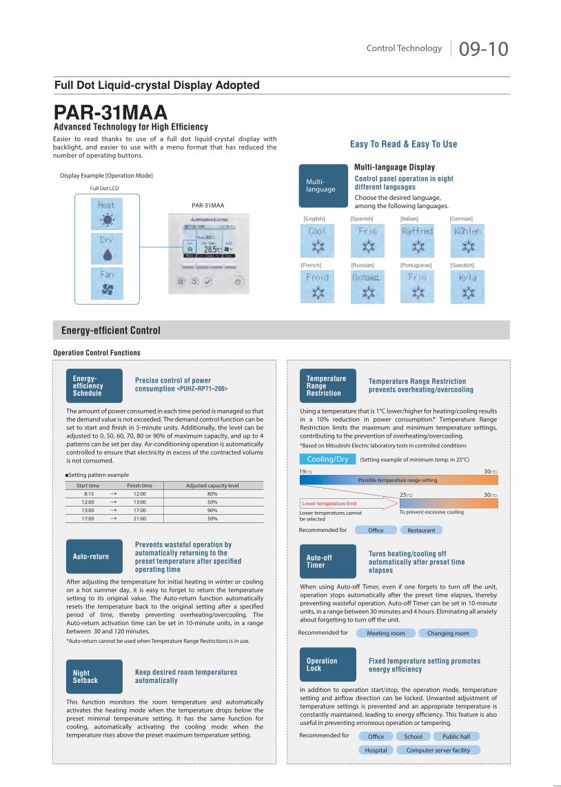
Sine-wave drive soft PWM
Smooth AC wave pattern
The inverter has been made more compact by inserting the circuitry inside a synthetic resin molding.To ensure quiet operation, soft PWM control is used to prevent the metallic whine associated with conventional inverters.
Advanced Technology for High Efficiency
Numerous Leading-edge Technologies
Assure High Efficiency
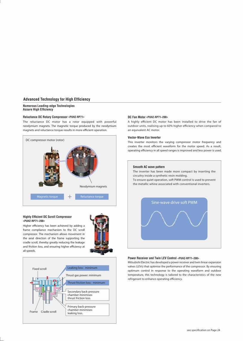
Reluctance DC Rotary Compressor <PUHZ-RP71>
The reluctance DC motor has a rotor equipped with powerful neodymium magnets. The magnetic torque produced by the neodymium magnets and reluctance torque results in more efficient operation.
Highly Efficient DC Scroll Compressor
<PUHZ-RP71–200>
Higher efficiency has been achieved by adding a frame compliance mechanism to the DC scroll compressor. The mechanism allows movement in the axial direction of the frame supporting the cradle scroll, thereby greatly reducing the leakage and friction loss, and ensuring higher efficiency at all speeds.
DC Fan Motor <PUHZ-RP71–200>
A highly efficient DC motor has been installed to drive the fan of outdoor units, realising up to 60% higher efficiency when compared to an equivalent AC motor.
Vector-Wave Eco Inverter
This inverter monitors the varying compressor motor frequency and creates the most efficient waveform for the motor speed. As a result, operating efficiency in all speed ranges is improved and less power is used.
Power Receiver and Twin LEV Control <PUHZ-RP71–200>
Mitsubishi Electric has developed a power receiver and twin linear expansion valves (LEVs) that optimise the performance of the compressor. By ensuring optimum control in response to the operating waveform and outdoor temperature, this technology is tailored to the characteristics of the new refrigerant to enhance operating efficiency.
DC compressor motor (rotor)
Thrust gas power: minimum
Cradle scrollFrame
Secondary back-pressurechamber minimisesthrust friction loss.
Primary back-pressurechamber minimisesleaking loss.
Thrust friction loss : minimum
Leaking loss : minimumFixed scroll
Neodymium magnets
+Magnetic torque Reluctance torque
see specification on Page 24
Control Technology 09-10
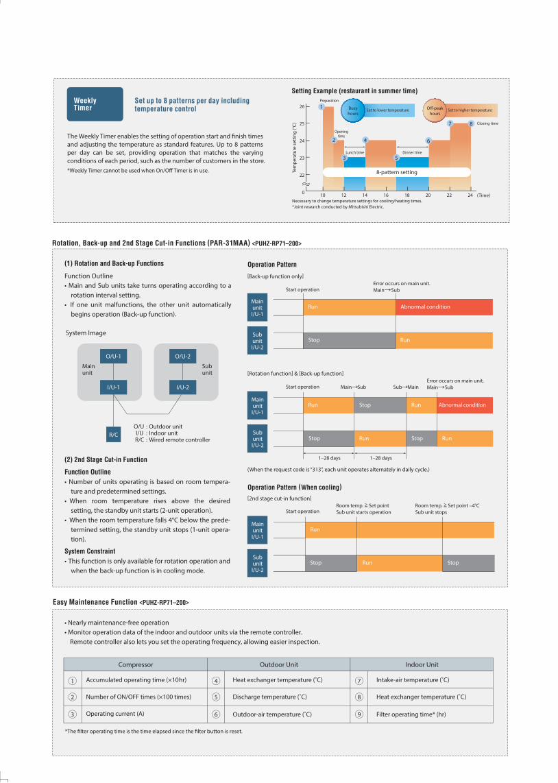
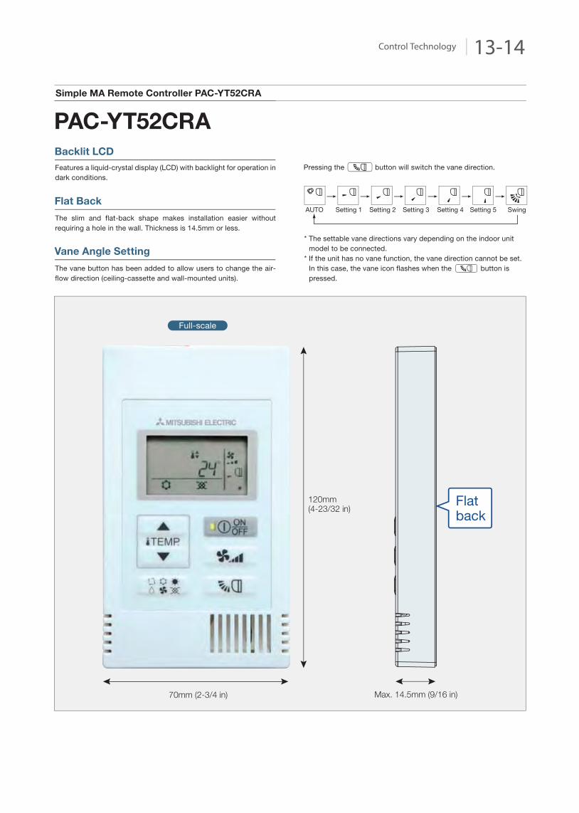
Easier to read thanks to use of a full dot liquid-crystal display with backlight, and easier to use with a menu format that has reduced the number of operating buttons.
The amount of power consumed in each time period is managed so that the demand value is not exceeded. The demand control function can be set to start and finish in 5-minute units. Additionally, the level can be adjusted to 0, 50, 60, 70, 80 or 90% of maximum capacity, and up to 4 patterns can be set per day. Air-conditioning operation is automatically controlled to ensure that electricity in excess of the contracted volume is not consumed.
Energy-efficient Control
Operation Control Functions
Precise control of power
consumption <PUHZ–RP71–200>
Easy To Read & Easy To Use
Multi-language Display
Control panel operation in eight
different languages
Display Example [Operation Mode]
Full Dot LCD
Energy-efficiencySchedule
Using a temperature that is 1°C lower/higher for heating/cooling results in a 10% reduction in power consumption.* Temperature Range Restriction limits the maximum and minimum temperature settings, contributing to the prevention of overheating/overcooling.*Based on Mitsubishi Electric laboratory tests in controlled conditions
Temperature Range Restriction
prevents overheating/overcooling
TemperatureRangeRestriction
When using Auto-off Timer, even if one forgets to turn off the unit, operation stops automatically after the preset time elapses, thereby preventing wasteful operation. Auto-off Timer can be set in 10-minute units, in a range between 30 minutes and 4 hours. Eliminating all anxiety about forgetting to turn off the unit.
Turns heating/cooling off
automatically after preset time
elapses
Auto-offTimer
After adjusting the temperature for initial heating in winter or cooling on a hot summer day, it is easy to forget to return the temperature setting to its original value. The Auto-return function automatically resets the temperature back to the original setting after a specified period of time, thereby preventing overheating/overcooling. The Auto-return activation time can be set in 10-minute units, in a range between 30 and 120 minutes.*Auto-return cannot be used when Temperature Range Restrictions is in use.
Prevents wasteful operation by
automatically returning to the
preset temperature after specified
operating time
Auto-return
This function monitors the room temperature and automatically activates the heating mode when the temperature drops below the preset minimal temperature setting. It has the same function for cooling, automatically activating the cooling mode when the temperature rises above the preset maximum temperature setting.
Keep desired room temperatures
automatically NightSetback
Choose the desired language, among the following languages.
Multi-Ianguage
[Swedish]
[English] [Italian] [German][Spanish]
[Russian] [Portuguese][French]
Setting pattern example
Start time 8:1512:0013:0017:00
Finish time12:0013:0017:0021:00
Adjusted capacity level80%50%90%50%
Cooling/Dry (Setting example of minimum temp. in 25°C)
Lower temperature limit
Possible temperature range setting
19(˚C) 30(˚C)
30(˚C)25(˚C)
To prevent excessive coolingLower temperatures cannotbe selected
Meeting room Changing roomRecommended for
In addition to operation start/stop, the operation mode, temperature setting and airflow direction can be locked. Unwanted adjustment of temperature settings is prevented and an appropriate temperature is constantly maintained, leading to energy efficiency. This feature is also useful in preventing erroneous operation or tampering.
Fixed temperature setting promotes
energy efficiency
OperationLock
Computer server facility
Recommended for Office School
Hospital
Public hall
Office RestaurantRecommended for
PAR-31MAA
Advanced Technology for High Efficiency
Full Dot Liquid-crystal Display Adopted
PAR-31MAA
The Weekly Timer enables the setting of operation start and finish times and adjusting the temperature as standard features. Up to 8 patterns per day can be set, providing operation that matches the varying conditions of each period, such as the number of customers in the store.*Weekly Timer cannot be used when On/Off Timer is in use.
Set up to 8 patterns per day including
temperature control
WeeklyTimer Busy
hours
5
Setting Example (restaurant in summer time)
26
25
24
23
22
0 10 12 14 16 18 20 22 24
Tem
pera
ture
set
ting
(°C)
Openingtime
Lunch time
Preparation
Dinner time
8-pattern setting
Closing time
Set to lower temperature Set to higher temperature1
2 4
3
6
7 8
(Time)Necessary to change temperature settings for cooling/heating times. *Joint research conducted by Mitsubishi Electric.
Off-peakhours
Heat exchanger temperature (˚C)
Discharge temperature (˚C)
Outdoor-air temperature (˚C)
Accumulated operating time (×10hr)
Number of ON/OFF times (×100 times)
Operating current (A)
Intake-air temperature (˚C)
Heat exchanger temperature (˚C)
Filter operating time* (hr)
Outdoor UnitCompressor Indoor Unit
4
5
6
1
2
3
7
8
9
*The filter operating time is the time elapsed since the filter button is reset.
Rotation, Back-up and 2nd Stage Cut-in Functions (PAR-31MAA) <PUHZ-RP71–200>
(1) Rotation and Back-up Functions
Function Outline• Main and Sub units take turns operating according to a
rotation interval setting.• If one unit malfunctions, the other unit automatically
begins operation (Back-up function).
Easy Maintenance Function <PUHZ-RP71–200>
• Nearly maintenance-free operation • Monitor operation data of the indoor and outdoor units via the remote controller.
Remote controller also lets you set the operating frequency, allowing easier inspection.
(2) 2nd Stage Cut-in Function
Function Outline
• Number of units operating is based on room tempera-ture and predetermined settings.
• When room temperature rises above the desiredsetting, the standby unit starts (2-unit operation).
• When the room temperature falls 4°C below the prede-termined setting, the standby unit stops (1-unit opera-tion).
System Constraint
• This function is only available for rotation operation and when the back-up function is in cooling mode.
Operation Pattern
System Image
O/U : Outdoor unit I/U : Indoor unit R/C : Wired remote controller
Operation Pattern (When cooling)
[Back-up function only]
Start operationError occurs on main unit.Main Sub
[Rotation function] & [Back-up function]
(When the request code is “313”, each unit operates alternately in daily cycle.)
Start operation
1–28 days 1–28 days
Main Sub Sub MainError occurs on main unit.Main Sub
MainunitI/U-1
SubunitI/U-2
Run
Stop
Abnormal condition
Run
MainunitI/U-1
SubunitI/U-2
Run Stop Run
Stop
Abnormal condition
Run Stop Run
[2nd stage cut-in function]
Start operationRoom temp. >= Set pointSub unit starts operation
Room temp. >= Set point –4°CSub unit stops
MainunitI/U-1
SubunitI/U-2
Run
Stop Run Stop
O/U-1 O/U-2
I/U-1
R/C
I/U-2
Subunit
Mainunit
Control Technology 11-12
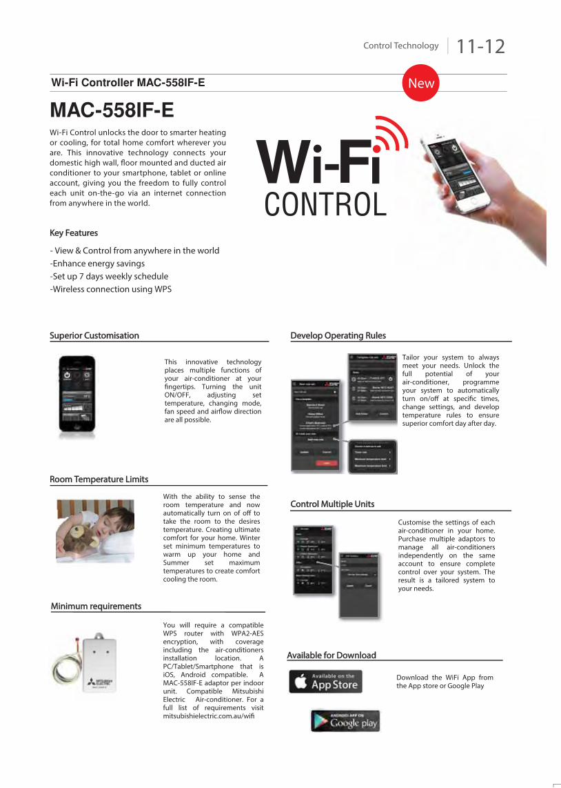
Wi-Fi Control unlocks the door to smarter heating or cooling, for total home comfort wherever you are. This innovative technology connects your domestic high wall, floor mounted and ducted air conditioner to your smartphone, tablet or online account, giving you the freedom to fully control each unit on-the-go via an internet connection from anywhere in the world.
This innovative technology places multiple functions of your air-conditioner at your fingertips. Turning the unit ON/OFF, adjusting set temperature, changing mode, fan speed and airflow direction are all possible.
Superior Customisation
Key Features
With the ability to sense the room temperature and now automatically turn on of off to take the room to the desires temperature. Creating ultimate comfort for your home. Winter set minimum temperatures to warm up your home and Summer set maximum temperatures to create comfort cooling the room.
Download the WiFi App from the App store or Google Play
Develop Operating Rules
Tailor your system to always meet your needs. Unlock the full potential of your air-conditioner, programme your system to automatically turn on/off at specific times, change settings, and develop temperature rules to ensure superior comfort day after day.
Customise the settings of each air-conditioner in your home. Purchase multiple adaptors to manage all air-conditioners independently on the same account to ensure complete control over your system. The result is a tailored system to your needs.
You will require a compatible WPS router with WPA2-AES encryption, with coverage including the air-conditioners installation location. A PC/Tablet/Smartphone that is iOS, Android compatible. A MAC-558IF-E adaptor per indoor unit. Compatible Mitsubishi Electric Air-conditioner. For a full list of requirements visit mitsubishielectric.com.au/wifi
Room Temperature Limits
Control Multiple Units
Available for Download
Minimum requirements
Wi-Fi Controller MAC-558IF-E
MAC-558IF-E
CONTROL- View & Control from anywhere in the world-Enhance energy savings-Set up 7 days weekly schedule-Wireless connection using WPS
New
PEAD/PEA
Main screen Zone control screen
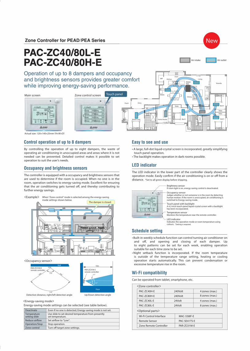
Zone Controller for PEAD/PEA Series
PAC-ZC40/80L-EPAC-ZC40/80H-E
New
Control operation of up to 8 dampers
By controlling the operation of up to eight dampers, the waste of operating air conditioning in unoccupied areas and areas where it is not needed can be prevented. Detailed control makes it possible to set operation to suit the user's needs.
LED indicator
The LED indicator in the lower part of the controller clearly shows the operation mode. Easily confirm if the air conditioning is on or off from a distance. *Set to all green display before shipping.
Easy to see and use
• A large, full-dot liquid-crystal screen is incorporated, greatly simplifying touch panel operation.
• The backlight makes operation in dark rooms possible.
Schedule setting
• Built-in weekly schedule function can control turning air conditioner on and off, and opening and closing of each damper. Upto eight patterns can be set for each week, enabling operationsuitable for each time zone to be set.
• Night setback function is incorporated. If the room temperatureis outside of the temperature range setting, heating or coolingoperation starts automatically. This can prevent condensation or excessive temperature rise in the room.
Wi-Fi compatibility
Can be operated from tablet, smartphone, etc.
Occupancy and brightness sensors
The controller is equipped with a occupancy and brightness sensors that are used to determine if the room is occupied. When no one is in the room, operation switches to energy-saving mode. Excellent for ensuring that the air conditioning gets turned off, and thereby contributing to further energy savings.
Actual size: 120×140×25mm (H×W×D)
<Example>
<Occupancy sensor>
<Energy-saving mode>
<Zone controller>
Detection distance, right/left detection angle Up/Down detection angle
PAR-ZC01M-Eremote controller
11°
10m
31°20°
Floor
10m10m
Wall
110°
PAR-ZC01M-Eremote controller
Brightness sensorIf room light is on, energy-saving control is deactivated.
Occupancy sensorJudges whether or not someone is in the room by detectinghuman motion. If the room is unoccupied, air conditioning isswitched to Energy-saving mode.
Touch panel with backlightA 4.3-inch touch-panel liquid-crystal screen with a backlighthas been incorporated.
Temperature sensorMonitors the temperature near the remote controller.
LED indicatorIndicates the operation mode or room temperature usingcolours. *Setting is required.
Operation of up to 8 dampers and occupancy and brightness sensors provides greater comfortwhile improving energy-saving performance.
Touch panel
PAC-ZC40H-E
PAC-ZC80H-E
PAC-ZC40L-E
PAC-ZC80L-E
4 zones (max.)
8 zones (max.)
4 zones (max.)
8 zones (max.)
<Optional parts>Wi-Fi Control Interface
Remote Sensor
Zone Remote Controller
240Volt
240Volt
24Volt
24Volt
MAC-558IF-E
PAC-SE41TS-E
PAR-ZC01M-E
Energy-saving mode settings can be selected (see table below).
Veranda
Living
Oven
Dining
Bed 2Home theaterMaster suite
Media
Entry
WR
WIP Kitchen
Porch
Robe
Robe
Robe
Bed 4
Bed 3
The damper is closed.
When “Zone control” mode is selected among the energy-savingmode settings shown below.
Air outletAir intake
Deactivate Even if no one is detected, Energy-saving mode is not set.Temperaturesetting slide
Use slide to set desired temperature from presentlyset temperature.
Reduce airflow Set airflow to “Low”.Operation/Stop Stop operation.Zone control Turn off target zone settings.
110°
Control Technology 13-14
15 PLA Series
PLA-RP60/71100/125/140BA
(i-see Sensor: optional)
optional
4-wayCeilingCassette
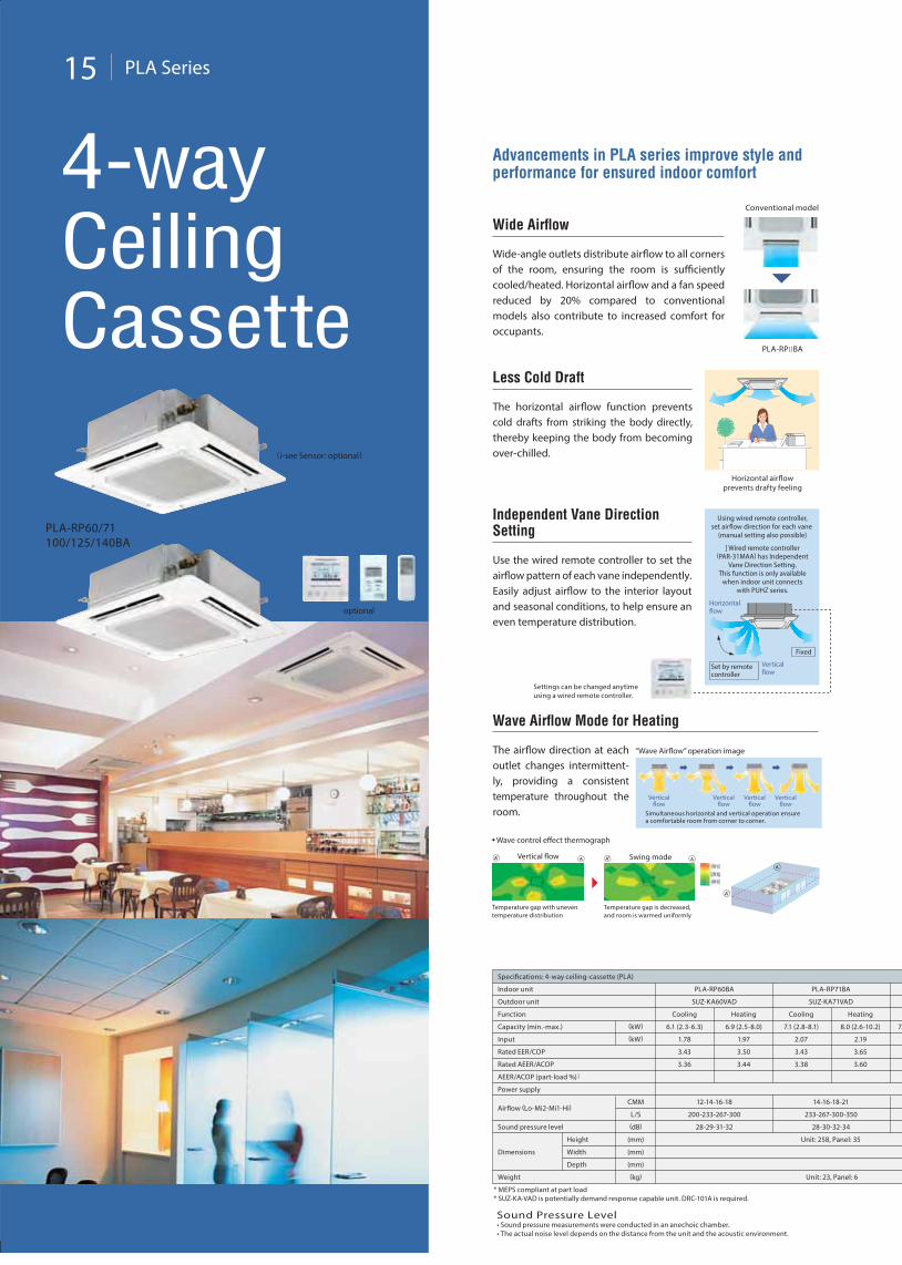
Advancements in PLA series improve style and performance for ensured indoor comfort
Wide Airflow
Wide-angle outlets distribute airflow to all corners of the room, ensuring the room is sufficiently cooled/heated. Horizontal airflow and a fan speed reduced by 20% compared to conventional models also contribute to increased comfort for occupants.
Conventional model
PLA-RP] ]BA
Less Cold Draft
The horizontal airflow function prevents cold drafts from striking the body directly, thereby keeping the body from becoming over-chilled.
Horizontal airflowprevents drafty feeling
Independent Vane DirectionSetting
Use the wired remote controller to set the airflow pattern of each vane independently. Easily adjust airflow to the interior layout and seasonal conditions, to help ensure an even temperature distribution.
Using wired remote controller,set airflow direction for each vane
(manual setting also possible) ] Wired remote controller
(PAR-31MAA) has IndependentVane Direction Setting.
This function is only availablewhen indoor unit connects
with PUHZ series.
Settings can be changed anytimeusing a wired remote controller.
Verticalflow
Horizontalflow
Set by remotecontroller
Fixed
Temperature gap with uneven temperature distribution
Temperature gap is decreased,and room is warmed uniformly
Swing modeVertical flow
Wave Airflow Mode for Heating
The airflow direction at each outlet changes intermittent-ly, providing a consistent temperature throughout the room.
Verticalflow
Verticalflow
Verticalflow
Verticalflow
Simultaneous horizontal and vertical operation ensurea comfortable room from corner to corner.
“Wave Airflow” operation image
• Wave control effect thermograph
Indoor unit
Specifications: 4-way ceiling-cassette (PLA)
PLA-RP60BA
SUZ-KA60VAD
Cooling Heating
Outdoor unit
Function
Capacity (min.-max.)
Input
Rated EER/COP
Power supply
Airflow (Lo-Mi2-Mi1-Hi)
Sound pressure level
Dimensions Width
Depth
Height
(kW)
(kW)
L/S
(dB)
(kg)
(mm)
(mm)
(mm)
Weight
* MEPS compliant at part load* SUZ-KA•VAD is potentially demand response capable unit. DRC-101A is required.
CMM
PLA-RP71BA
12-14-16-18 14-16-18-21
200-233-267-300 233-267-300-350
28-29-31-32 28-30-32-34
SUZ-KA71VAD
Cooling Heating
6.1 (2.3-6.3) 6.9 (2.5-8.0) 7.1 (2.8-8.1) 8.0 (2.6-10.2)
1.78 1.97 2.07 2.19
3.43 3.50 3.43 3.65
Unit: 258, Panel: 35
Unit: 23, Panel: 6
7.
Rated AEER/ACOP
AEER/ACOP (part-load %) ]
3.36 3.44 3.38 3.60
Sound Pressure Level• Sound pressure measurements were conducted in an anechoic chamber.• The actual noise level depends on the distance from the unit and the acoustic environment.
PLA Series 16
Auto Fan Speed Mode
The fan speed is adjusted automatically, thereby helping to maintain a comfortable room environment at all times. At the start of operation, a high fan speed provides quick heating/cooling of the room. Once the desired temperature is reached, the fan speed is reduced for stable heating/cooling and greater comfort.
HiLo AutoMi2 Mi1
Fan speed setting by remote controller (four levels)
]Special setting is required for wireless remote controller.
Quiet Operation
An improved airflow path and powerful high-capacity flow fan contribute to the realisation of quieter operation.
Power flow fan
“Pure White” Colour
Stylish, pure white-coloured panels and wired remote controller present a clean, streamlined image that is a suitable match for any interior.
Other Features
• Stylish indoor-unit vane covers (when unit is turned off) • Maximum upward draining of 850mm• Wireless remote controller available• Duct flange for Fresh-air Intake• Branch duct
Automatic Grille LoweringFunction (Option)
Easy to use/Simple maintenanceAn automatic grille lowering function capable of stopping at eight different heights is available to simplify filter maintenance.
Packaged elevating (up-down) controller in the grille (PLP-6BAJ) can be used when indoor unit connects with PUHZ series and SUZ series.
1.2m
1.6m
2.0m
2.4m
2.8m
3.2m
3.6m
4.0m
Automaticelevation tofour metres
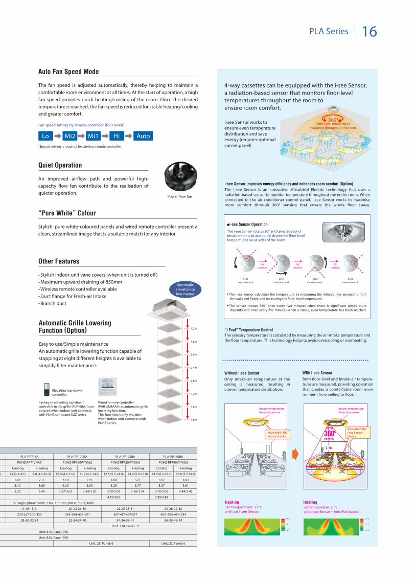
4-way cassettes can be equipped with the i-see Sensor, a radiation-based sensor that monitors floor-level temperatures throughout the room toensure room comfort.
i-see Sensor works to ensure even temperature distribution and save energy (requires optional corner panel)
i-see Sensor improves energy efficiency and enhances room comfort (Option)
The i-see Sensor is an innovative Mitsubishi Electric technology that uses a radiation-based sensor to monitor temperature throughout the entire room. When connected to the air conditioner control panel, i-see Sensor works to maximise room comfort through 360° sensing that covers the whole floor space.
The i-see Sensor rotates 90° and takes 5-second measurements to accurately determine floor-level temperatures on all sides of the room.
i-see Sensor Operation
• The i-see Sensor calculates the temperature by measuring the infrared rays emanating from the walls and floors, and measuring the floor-level temperature.
• The sensor rotates 360° once every two minutes when there is significant temperature disparity and once every five minutes when a stable, even temperature has been reached.
90°rotation
90°rotation
90°rotation
5secmeasurement
5secmeasurement
5secmeasurement
5secmeasurement
360°Floor-level temperature
measured throughout the room.
2.7m
Set temperature: 20°Cwith i-see Sensor + Auto Fan Speed
Without i-see Sensor With i-see Sensor
Area which the“i-see Sensor”checks
Indoor temperaturedetecting sensor
Indoor temperaturedetecting sensor
Area which thesensor checks
Set temperature: 23°Cwithout i-see Sensor
37°C
“I Feel” Temperature Control
The sensory temperature is calculated by measuring the air-intake temperature and the floor temperature. This technology helps to avoid overcooling or overheating.
sensing
11.5m
2.7m
sensing
11.5m
25°C
13°C
37°C
25°C
13°C
Heating Heating
2.7m
Area which thei-see Sensorchecks
Indoor temperaturedetecting sensor
Indoor temperaturedetecting sensor
Area which thesensor checks 360°360°
sensing
11.5m
2.7m
sensing
11.5m
Only intake-air temperature at the ceiling is measured, resulting in uneven temperature distribution.
Both floor-level and intake-air tempera-tures are measured, providing operation that creates a comfortable room envi-ronment from ceiling to floor.
Wired remote controller (PAR-31MAA) has automatic grille lowering function.This function is only available when indoor unit connects with PUHZ series.
Elevating (up-down) controller
2)
PLA-RP71BA
14-16-18-21
233-267-300-350
28-30-32-34
PUHZ-RP71VHA5
Cooling Heating
PLA-RP100BA
20-23-26-30
334-384-434-501
32-34-37-40
Unit: 25, Panel: 6
22-25-28-31
367-417-467-517
34-36-39-41
Unit: 840, Panel: 950
Unit: 298, Panel: 35
Unit: 840, Panel: 950
24-26-29-32
400-434-484-534
36-39-42-44
Unit: 27, Panel: 6
PUHZ-RP100V/YKA2
Cooling Heating
PLA-RP125BA
V: Single-phase, 50Hz, 230V Y: Three-phase, 50Hz, 400V
PUHZ-RP125V/YKA2
Cooling Heating
PLA-RP140BA
PUHZ-RP140V/YKA2
Cooling Heating
13.0 (6.2-15.3)
3.97
3.27
16.0 (5.7-18.0)
4.43
3.61
12.5 (5.5-14.0)
3.80
3.29
14.0 (5.0-16.0)
3.71
3.77
10.0 (4.9-11.4)
2.50
4.00
11.2 (4.5-14.0)
2.95
3.80
2.09
3.40
2.17
7.1 (3.3-8.1) 8.0 (3.5-10.2)
3.69
3.10/3.08
3.95/3.89
3.44/3.423.10/3.08
4.13/4.05
3.56/3.543.67/3.63 3.54/3.503.22 3.49
17 PEAD Series
PEAD-RP71/100/125/140JAA
optional
Ceiling-concealed
optional
NEW
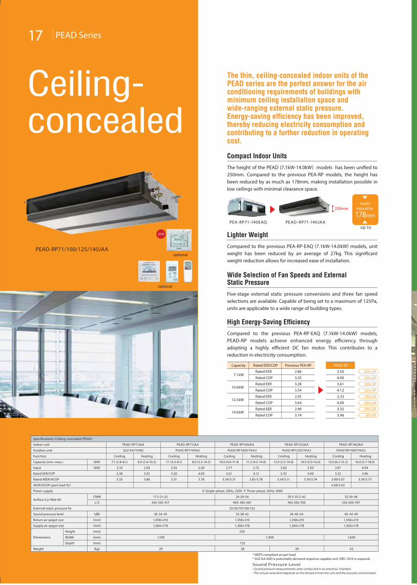
The thin, ceiling-concealed indoor units of the PEAD series are the perfect answer for the air conditioning requirements of buildings with minimum ceiling installation space and wide-ranging external static pressure. Energy-saving efficiency has been improved, thereby reducing electricity consumption and contributing to a further reduction in operating cost.
Compact Indoor Units
The height of the PEAD (7.1kW-14.0kW) models has been unified to 250mm. Compared to the previous PEA-RP models, the height has been reduced by as much as 178mm, making installation possible in low ceilings with minimal clearance space.
Lighter Weight
Compared to the previous PEA-RP•EAQ (7.1kW-14.0kW) models, unit weight has been reduced by an average of 27kg. This significant weight reduction allows for increased ease of installation.
High Energy-Saving Efficiency
Compared to the previous PEA-RP•EAQ (7.1kW-14.0kW) models, PEAD-RP models achieve enhanced energy efficiency through adopting a highly efficient DC fan motor. This contributes to a reduction in electricity consumption.
Wide Selection of Fan Speeds and ExternalStatic Pressure
Five-stage external static pressure conversions and three fan speed selections are available. Capable of being set to a maximum of 125Pa, units are applicable to a wide range of building types.
PEA-RP71-140EAQ PEAD-RP71-140JAA
7.1kW
10.0kW
12.5kW
14.0kW
Rated EER
Rated COP
Rated EER
Rated COP
Rated EER
Rated COP
Rated EER
Rated COP
2.86
3.35
3.28
3.54
2.95
3.64
2.90
3.74
Capacity Rated EER/COP Previous PEA-RP
3.50
4.00
3.61
4.12
3.33
4.00
3.32
3.96
22% UP
19% UP
10% UP
16% UP
13% UP
10% UP
14% UP
6% UP
PEAD-RP
250mmHeight
reduced by
178mm
up to
Indoor unit
Specifications: Ceiling-concealed (PEAD)
PEAD-RP71JAA
SUZ-KA71VAD
Cooling Heating
Outdoor unit
Function
Capacity (min.-max.)
Input
Rated EER/COP
Power supply
Airflow (Lo-Mid-Hi)
Sound pressure level
Dimensions Width
Depth
Height
(kW)
(kW)
L/S
(dB)
(kg)
(mm)
(mm)
(mm)
Weight
* MEPS compliant at part load* SUZ-KA•VAD is potentially demand response capable unit. DRC-101A is required.
CMM
PEAD-RP71JAA
24-29-34
400-483-567
33-38-42
External static pressure Pa 35/50/70/100/125
PUHZ-RP71VHA5
Cooling Heating
7.1 (2.8-8.1) 8.0 (2.6-10.2) 7.1 (3.3-8.1) 8.0 (3.5-10.2)
2.10 2.04 2.03 2.00
3.38 3.92 3.50 4.00
PEAD-RP100JAA
PUHZ-RP100V/YKA2
Cooling Heating
V: Single-phase, 50Hz, 230V Y: Three-phase, 50Hz, 400V
250
1,400
732
38
17.5-21-25
292-350-417
30-34-39
1,100
29
2.77
3.61
2.72
10.0 (4.9-11.4) 11.2 (4.5-14.0)
4.12
Rated AEER/ACOP
AEER/ACOP (part-load %) ]
3.33 3.86 3.31 3.78 3.34/3.31 3.81/3.78
29.5-35.5-42
492-592-700
36-40-44
PEAD-RP125JAA
PUHZ-RP125V/YKA2
Cooling Heating
39
3.60
3.33
3.50
12.0 (5.5-14.0) 14.0 (5.0-16.0)
4.00
3.14/3.11 3.76/3.74
32-39-46
533-650-767
40-44-49
Return air spigot size (mm)
1,360×1781,060×178
1,058×210
1,360×178 1,560×178
1,358×210 1,358×210 1,558×210
Supply air spigot size (mm)
PEAD-RP140JAA
PUHZ-RP140V/YKA2
Cooling Heating
1,600
43
3.91
3.32
4.04
13.0 (6.2-15.3) 16.0 (5.7-18.0)
3.96
3.09/3.07
3.68/3.63
3.76/3.73
Sound Pressure Level• Sound pressure measurements were conducted in an anechoic chamber.• The actual noise level depends on the distance from the unit and the acoustic environment.
18 PEA Series
PEA-RP170/200WJA/250WHA
optional
PEA-RP100/125/140GAA
Ceiling-concealed
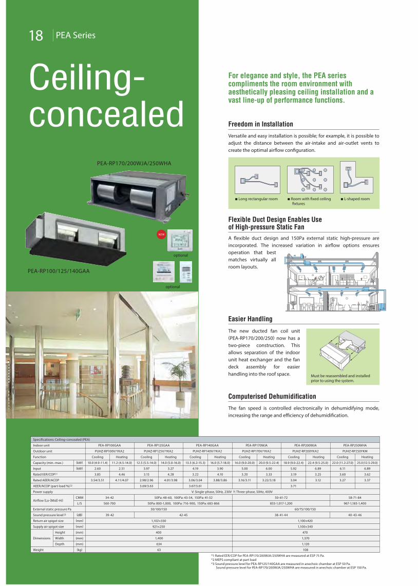
Easier Handling
The new ducted fan coil unit (PEA-RP170/200/250) now has a two-piece construction. This allows separation of the indoor unit heat exchanger and the fan deck assembly for easier handling into the roof space.
Computerised Dehumidification
The fan speed is controlled electronically in dehumidifying mode, increasing the range and efficiency of dehumidification.
Freedom in Installation
Versatile and easy installation is possible; for example, it is possible to adjust the distance between the air-intake and air-outlet vents to create the optimal airflow configuration.
Long rectangular room Room with fixed ceilingfixtures
L-shaped room
Must be reassembled and installedprior to using the system.
Flexible Duct Design Enables Useof High-pressure Static Fan
A flexible duct design and 150Pa external static high-pressure are incorporated. The increased variation in airflow options ensuresoperation that best matches virtually all room layouts.
optional
NEW
For elegance and style, the PEA series compliments the room environment with aesthetically pleasing ceiling installation and a vast line-up of performance functions.
*1 Rated EER/COP for PEA-RP170/200WJA/250WHA are measured at ESP 75 Pa.*2 MEPS compliant at part load*3 Sound pressure level for PEA-RP125/140GAA are measured in anechoic chamber at ESP 50 Pa. Sound pressure level for PEA-RP170/200WJA/250WHA are measured in anechoic chamber at ESP 150 Pa.
Indoor unit
Specifications: Ceiling-concealed (PEA)
Outdoor unit
Function
Capacity (min.-max.)
Input
Rated EER/COP ]1
Power supply
Airflow (Lo-[Mid]-Hi)
Sound pressure level ]3
Dimensions Width
Depth
Height
(kW)
(kW)
L/S
(dB)
(kg)
(mm)
(mm)
(mm)
Weight
CMM
PEA-RP170WJA
Return air spigot size (mm)
Supply air spigot size (mm)
External static pressure Pa
PUHZ-RP170V/YKA2
Cooling Heating
16.0 (9.0-20.0) 20.0 (9.5-22.4)
5.00 6.00
3.20 3.33
PEA-RP200WJA
PUHZ-RP200YKA2
Cooling Heating
V: Single-phase, 50Hz, 230V Y: Three-phase, 50Hz, 400V
50-61-72
833-1,017-1,200
34-42
560-700
38-41-44
1,100×420
1,100×340
60/75/100/150
470
1,370
1,120
108
50Pa: 48-60, 100Pa: 43-54, 150Pa: 41-52
50Pa: 800-1,000, 100Pa: 716-900, 150Pa: 683-866
42-4539-42
1,102×330
921×250
50/100/150
400
1,400
634
63
5.92
3.19
6.89
18.9 (9.0-22.4) 22.4 (9.5-25.0)
3.25
Rated AEER/ACOP
AEER/ACOP (part-load %) ]2
PEA-RP140GAA
PUHZ-RP140V/YKA2
Cooling Heating
13.5 (6.2-15.3) 16.0 (5.7-18.0)
4.19 3.90
3.22 4.10
3.06/3.04
3.67/3.61
3.88/3.86
PEA-RP125GAA
PUHZ-RP125V/YKA2
Cooling Heating
12.5 (5.5-14.0) 14.0 (5.0-16.0)
3.97 3.27
3.15 4.28
2.98/2.96
3.69/3.63
4.01/3.98
PEA-RP100GAA
PUHZ-RP100V/YKA2
Cooling Heating
10.0 (4.9-11.4) 11.2 (4.5-14.0)
2.60 2.51
3.85 4.46
3.54/3.51 4.11/4.07 3.16/3.11 3.22/3.18 3.04
3.71
3.12
PEA-RP250WHA
PUHZ-RP250YKM
Cooling Heating
22.0 (11.2-27.0) 25.0 (12.5-29.0)
6.11 6.89
3.60 3.62
58-71-84
967-1,183-1,400
40-43-46
3.27 3.37
19 PCA Series
PCA-RP50/60/71/100/125/140KAQ
optional
Ceiling-suspended
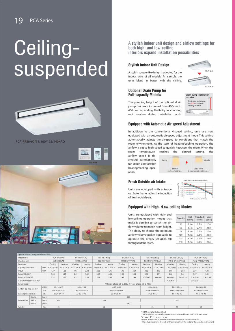
A stylish indoor unit design and airflow settings for both high- and low-ceiling interiors expand installation possibilities
Stylish Indoor Unit Design
A stylish square-like design is adopted for the indoor units of all models. As a result, the units blend in better with the ceiling.
PCA-GA
PCA-KA
Optional Drain Pump for Full-capacity Models
The pumping height of the optional drain pump has been increased from 400mm to 600mm, expanding flexibility in choosing unit location during installation work.
Drainage outlet canbe 600mm aboveceiling surface
Drain pump installationpossible
Ceilingsurface
Equipped with Automatic Air-speed Adjustment
In addition to the conventional 4-speed setting, units are now equipped with an automatic air-speed adjustment mode. This setting automatically adjusts the air-speed to conditions that match the room environment. At the start of heating/cooling operation, the airflow is set to high-speed to quickly heat/cool the room. When the room temperature reaches the desired setting, theairflow speed is de-creased automatically for stable comfortable heating/cooling oper-ation.
Start ofcooling/heating…
After roomtemperature is stabilised…
Strong Gentle
Fresh Outside-air Intake
Units are equipped with a knock-out hole that enables the induction of fresh outside-air.
Airflow volume (m3/min)
500
–50–100–150–200–250–300
0 1 2 3 4
Stat
ic p
ress
ure
(Pa)
l Outside-air intake characteristics
PCA-RP100–140KAPCA-RP60/71KAPCA-RP50KA
Capacity Highceiling
Standardceiling
Lowceiling
50
60
71
100
125
140
3.5m
3.5m
3.5m
4.2m
4.2m
4.2m
2.7m
2.7m
2.7m
3.0m
3.0m
3.0m
2.5m
2.5m
2.5m
2.6m
2.6m
2.6m
Equipped with High- /Low-ceiling Modes
Units are equipped with high- and low-ceiling operation modes that make it possible to switch the air-flow volume to match room height. The ability to choose the optimum airflow volume makes it possible to optimise the breezy sensation felt throughout the room.
Indoor unit
Specifications: Ceiling-suspended (PCA)
PCA-RP50KAQ
SUZ-KA50VAD
Cooling Heating
PCA-RP60KAQ
SUZ-KA60VAD
Cooling Heating
PCA-RP71KAQ
167-183-217-250 250-267-283-317 267-283-300-333
32-34-37-40
960
25
33-35-37-40
1,280
35-37-39-41
SUZ-KA71VAD
Cooling Heating
4.9 (2.3-5.6) 5.5 (1.7-7.2) 5.7 (2.3-6.3) 6.9 (2.5-8.0) 7.1 (2.8-8.1) 7.9 (2.6-10.2)
1.49 1.68 1.67 2.02 2.06 1.96
3.29 3.27 3.41 3.42 3.45 4.03
PCA-RP71KAQ
PUHZ-RP71VHA5
Cooling Heating
PCA-RP100KAQ
PUHZ-RP100V/YKA2
Cooling Heating
PCA-RP125KAQ
PUHZ-RP125V/YKA2
Cooling Heating
PCA-RP140KAQ
PUHZ-RP140V/YKA2
Cooling Heating
10.0 (4.9-11.4) 11.2 (4.5-14.0) 12.0 (5.5-14.0) 14.0 (5.0-16.0) 13.0 (6.2-15.3) 16.0 (5.7-18.0)
2.63 3.02 3.66 3.88 3.97 4.43
3.80 3.71
7.1 (3.3-8.1) 8.0 (3.5-10.2)
1.96 2.21
3.62 3.62 3.28 3.61 3.27 3.61
V: Single-phase, 50Hz, 230V Y: Three-phase, 50Hz, 400V
367-400-433-467 383-417-450-483 400-433-483-533
37-39-41-43 39-41-43-45 41-43-45-48
230
1,600
680
36
10-11-13-15 15-16-17-19 16-17-18-20 22-24-26-28 23-25-27-29 24-26-29-32
32 38 39
Outdoor unit
Function
Capacity (min.-max.)
Input
Rated EER/COP
3.22 3.22 3.35 3.36 3.39 3.96 3.50/3.47 3.46/3.433.42 3.44 3.09/3.07 3.41/3.39 3.10/3.08
4.19/4.11 3.91/3.85
3.41/3.39Rated AEER/ACOP
Power supply
Airflow (Lo-Mi2-Mi1-Hi)
Sound pressure level
Dimensions Width
Depth
Height
(kW)
(kW)
L/S
CMM
(dB)
(kg)
(mm)
(mm)
(mm)
Weight
* MEPS compliant at part load* SUZ-KA•VAD is potentially demand response capable unit. DRC-101A is required.
AEER/ACOP (part-load %) ]
Sound Pressure Level• Sound pressure measurements were conducted in an anechoic chamber.• The actual noise level depends on the distance from the unit and the acoustic environment.
20 PKA Series
PKA-RP71/100KAL
optional standard
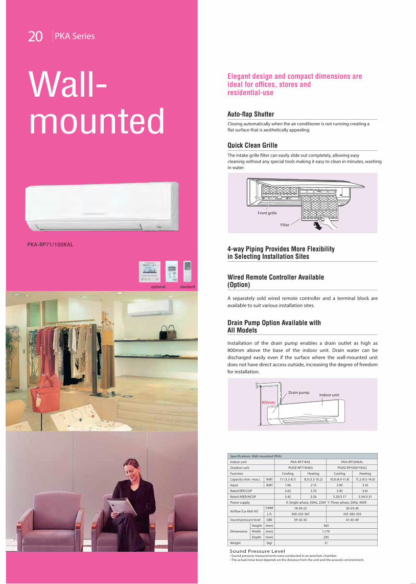
Wall-mounted Auto-flap Shutter
Quick Clean Grille
The intake grille filter can easily slide out completely, allowing easy cleaning without any special tools making it easy to clean in minutes, washing in water.
Closing automatically when the air conditioner is not running creating a flat surface that is aesthetically appealing.
4-way Piping Provides More Flexibilityin Selecting Installation Sites
Wired Remote Controller Available (Option)
A separately sold wired remote controller and a terminal block are available to suit various installation sites.
Drain Pump Option Available withAll Models
Installation of the drain pump enables a drain outlet as high as 800mm above the base of the indoor unit. Drain water can be discharged easily even if the surface where the wall-mounted unit does not have direct access outside, increasing the degree of freedom for installation.
Elegant design and compact dimensions are ideal for offices, stores andresidential-use
Front grille
Filter
800mm
Drain pump Indoor unit
Indoor unit
Specifications: Wall-mounted (PKA)
PKA-RP71KAL
PUHZ-RP71VHA5
Cooling Heating
PKA-RP100KAL
V: Single-phase, 50Hz, 230V Y: Three-phase, 50Hz, 400V
20-23-26
333-383-433
41-45-49
365
1,170
295
21
18-20-22
300-333-367
39-42-45
PUHZ-RP100V/YKA2
Cooling Heating
10.0 (4.9-11.4) 11.2 (4.5-14.0)
2.90 3.10
3.45 3.61
7.1 (3.3-8.1) 8.0 (3.5-10.2)
1.96 2.13
3.62 3.76
Outdoor unit
Function
Capacity (min.-max.)
Input
Rated EER/COP
3.20/3.17 3.34/3.313.42 3.56Rated AEER/ACOP
Power supply
Airflow (Lo-Mid-Hi)
Sound pressure level
Dimensions Width
Depth
Height
(kW)
(kW)
L/S
(dB)
(kg)
(mm)
(mm)
(mm)
Weight
CMM
Sound Pressure Level• Sound pressure measurements were conducted in an anechoic chamber.• The actual noise level depends on the distance from the unit and the acoustic environment.
21 SLZ /SEZ Series
CompactBulkhead
SLZ-KA25/50VAQ (L)
SEZ-KD25/35/50/60/71VAQ (L)
standard forSLZ-VAL
standard forSEZ-VAL
optional for SLZ/SEZ-VAQ
optional for SLZ/SEZ-VAQ
4-wayCeilingCassette
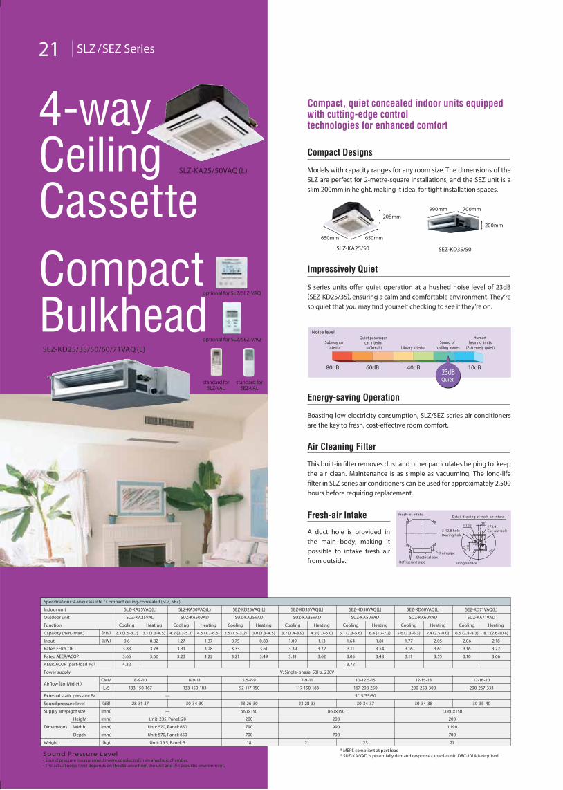
Compact, quiet concealed indoor units equipped with cutting-edge controltechnologies for enhanced comfort
Fresh-air Intake
A duct hole is provided in the main body, making it possible to intake fresh air from outside.
Energy-saving Operation
Boasting low electricity consumption, SLZ/SEZ series air conditioners are the key to fresh, cost-effective room comfort.
Air Cleaning Filter
This built-in filter removes dust and other particulates helping to keep the air clean. Maintenance is as simple as vacuuming. The long-life filter in SLZ series air conditioners can be used for approximately 2,500 hours before requiring replacement.
Compact Designs
Models with capacity ranges for any room size. The dimensions of the SLZ are perfect for 2-metre-square installations, and the SEZ unit is a slim 200mm in height, making it ideal for tight installation spaces.
SLZ-KA25/50
650mm 650mm
208mm
SEZ-KD35/50
990mm 700mm
200mm
Impressively Quiet
S series units offer quiet operation at a hushed noise level of 23dB (SEZ-KD25/35), ensuring a calm and comfortable environment. They’re so quiet that you may find yourself checking to see if they’re on.
23dBQuiet!
l Noise level
Subway car interior
Quiet passenger car interior (40km/h) Library interior
Sound of rustling leaves
Human hearing limits
(Extremely quiet)
10dB40dB60dB80dB
25
120°
120°11
8
Fresh-air intake
Refrigerant pipeElectrical box
Drain pipe
Detail drawing of fresh-air intake
100Cut-out hole
73.43- 2.8 holeBurring hole
Ceiling surface
Indoor unit
Specifications: 4-way cassette / Compact ceiling-concealed (SLZ, SEZ)
SLZ-KA25VAQ(L)
SUZ-KA25VAD
Cooling Heating
SLZ-KA50VAQ(L)
SUZ-KA50VAD
Cooling Heating
SEZ-KD25VAQ(L)
133-150-167 133-150-183 92-117-150
28-31-37 30-34-39 23-26-30
200
790
700
18
SUZ-KA25VAD
Cooling Heating
2.3 (1.5-3.2) 3.1 (1.3-4.5) 4.2 (2.3-5.2) 4.5 (1.7-6.5) 2.5 (1.5-3.2) 3.0 (1.3-4.5)
0.6 0.82 1.27 1.37 0.75 0.83
3.83 3.78 3.31 3.28 3.33 3.61
SEZ-KD35VAQ(L)
SUZ-KA35VAD
Cooling Heating
SEZ-KD50VAQ(L)
SUZ-KA50VAD
Cooling Heating
SEZ-KD60VAQ(L)
SUZ-KA60VAD
Cooling Heating
SEZ-KD71VAQ(L)
SUZ-KA71VAD
Cooling Heating
5.1 (2.3-5.6) 6.4 (1.7-7.2) 5.6 (2.3-6.3) 7.4 (2.5-8.0) 6.5 (2.8-8.3) 8.1 (2.6-10.4)
1.64 1.81 1.77 2.05 2.06 2.18
3.11 3.54
3.7 (1.4-3.9) 4.2 (1.7-5.0)
1.09 1.13
3.39 3.72 3.16 3.61 3.16 3.72
V: Single-phase, 50Hz, 230V
167-208-250 200-250-300 200-267-333
30-34-37 30-34-38 30-35-40
Unit: 235, Panel: 20
Unit: 570, Panel: 650
Unit: 570, Panel: 650
Unit: 16.5, Panel: 3
—
—
23
8-9-10 8-9-11 5.5-7-9
117-150-183
23-28-33
200
990
700
200
1,190
700
21 27
7-9-11 10-12.5-15 12-15-18 12-16-20
Outdoor unit
Function
Capacity (min.-max.)
Input
Rated EER/COP
3.65
4.32
3.66 3.23 3.22 3.21 3.49 3.05
3.72
3.483.31 3.62 3.11 3.55 3.10 3.66Rated AEER/ACOP
Power supply
Airflow (Lo-Mid-Hi)
Sound pressure level
Dimensions Width
Depth
Height
(kW)
(kW)
L/S
CMM
(dB)
(kg)
(mm)
(mm)
(mm)
Weight
* MEPS compliant at part load* SUZ-KA•VAD is potentially demand response capable unit. DRC-101A is required.
AEER/ACOP (part-load %) ]
5/15/35/50External static pressure Pa
660×150 860×150 1,060×150Supply air spigot size (mm)
Sound Pressure Level• Sound pressure measurements were conducted in an anechoic chamber.• The actual noise level depends on the distance from the unit and the acoustic environment.
Main Features 22
*1 When multiple indoor units connected to an MXZ outdoor unit are running at the same time, simultaneous cooling and heating is not possible.
*2 Please refer “System Control” on page 21 for details.*3 Not available with PEA-RP170/200WJA and PEA-RP250WHA models.*4 Schedule timer not available
External contact only
*5 Remote controller timer function only*6 Only error display on remote controller*7 PUHZ-RP250 is excluded.
PUHZ-RP •VHA5R1-A, PUHZ-RP •V /YKA2R1-A are only demand response capable withthe demand function. Please contact Mitsubishi Electric Australia Pty. Ltd. for details.
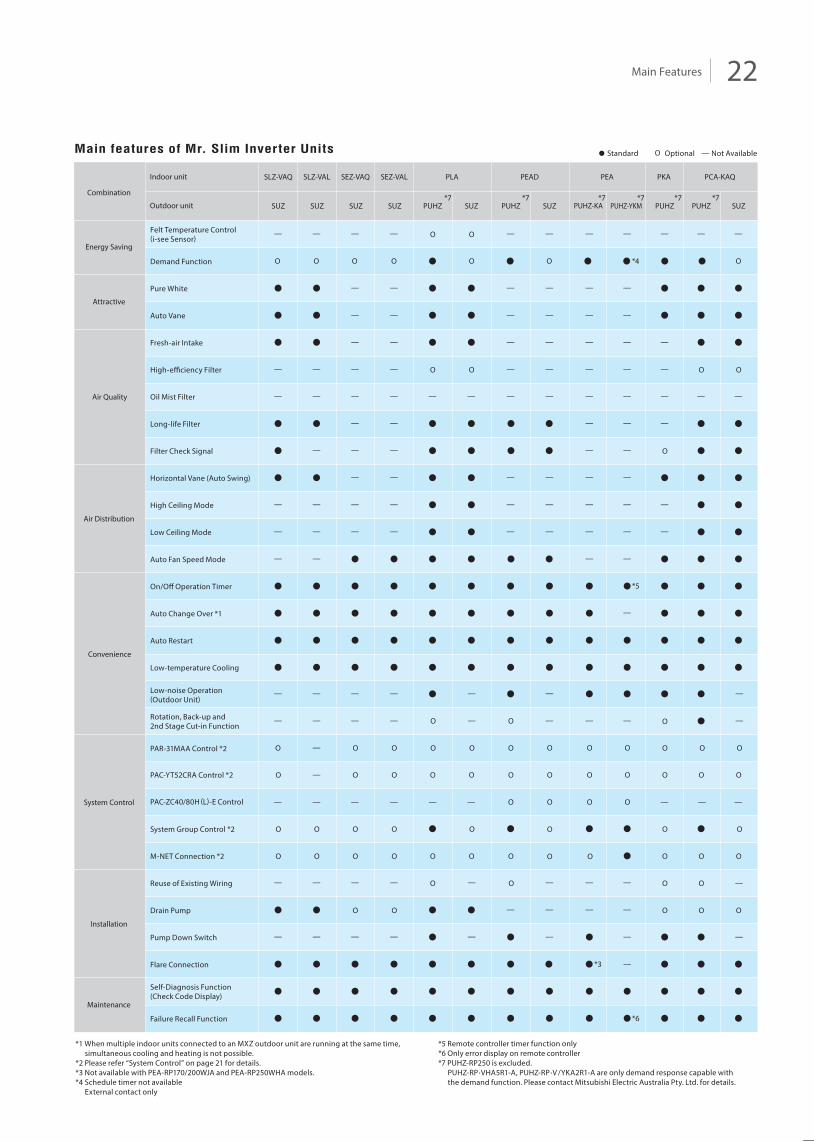
Main features of Mr. Slim Inverter Units
Felt Temperature Control(i-see Sensor)
Pure White
Demand Function
Auto Vane
Fresh-air Intake
High-efficiency Filter
Oil Mist Filter
Long-life Filter
Filter Check Signal
Horizontal Vane (Auto Swing)
High Ceiling Mode
Auto Fan Speed Mode
On/Off Operation Timer
Auto Change Over *1
Auto Restart
Low-temperature Cooling
Low-noise Operation(Outdoor Unit)
Rotation, Back-up and2nd Stage Cut-in Function
PAR-31MAA Control *2
PAC-YT52CRA Control *2
System Group Control *2
M-NET Connection *2
Reuse of Existing Wiring
Drain Pump
Pump Down Switch
Flare Connection
Self-Diagnosis Function(Check Code Display)
Failure Recall Function
Energy Saving
Combination
Outdoor unit
Indoor unit
Attractive
Air Quality
Air Distribution
Convenience
System Control
Installation
Maintenance
O
O
O
SLZ-VAQ
SUZ SUZ SUZ SUZ
SLZ-VAL
O
O
SEZ-VAQ
O
O
O
O
SEZ-VAL
O
O
O O
O
PLA
PUHZ PUHZ PUHZ-YKMSUZ
O
O O
O
O
O
O
O
O
O
PEAD PEA
SUZ
O
O O
O
O O
PKA
O
O
O
O O
O
O
O
PCA-KAQ
PUHZPUHZPUHZ-KA SUZ
O
O
O
O
O
O
O
O
O
O O O OO O
O O
O O OO
O
O
*3
*6
*7 *7*7 *7 *7*7
*4
*5
O
PAC-ZC40/80H (L)-E Control O O O O
Low Ceiling Mode
O
OO O O O O O
Optional Not AvailableOStandard
23 System Controls
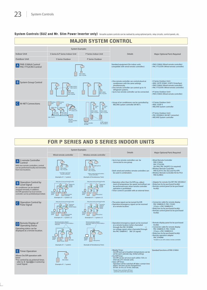
MAJOR SYSTEM CONTROL
FOR P SERIES AND S SERIES INDOOR UNITS
2-remote Controller Control
With two remote controllers, control can be performed locally and remotely from two locations.
Operation Control by Level Signal
Air conditioner can be started/stopped remotely. In addition, On/Off operation by local remote controller can be prohibited/permitted.
Operation Control by Pulse Signal
Remote Display of Operating Status
Operating status can be displayed at a remote location.
Allows On/Off operation with timer*For control by an external timer,
refer to B Operation Control by Level Signal.
Timer Operation
• Wired Remote ControllerPAR-31MAAPAC-YT52CRA(for PKA, PAC-SH29TC-E is required)
• Wireless Remote ControllerPAR-SL97A-E (for SEZ and PLA-RP)
• Wireless Remote Controller Kit for PCAPAR-SL94B-E
• Adapter for remote On/Off PAC-SE55RA-E• Relay box (to be purchased locally)• Remote control panel (to be purchased
locally)
Standard functions of PAR-31MAA
A
B
C
D
E
Details Major Optional Parts RequiredSystem Examples
Wired remote controller Wireless remote controller
• Up to two remote controllers can be connected to one group.
• Both wired and wireless remote controllers can be used in combination.
• Operation other than On/Off (e.g., adjust-ment of temperature, fan speed, and airflow) can be performed even when remote controller operation is prohibited.
• Timer control is possible with an external timer.
• Connector cable for remote display PAC-SA88HA-E / PAC-725AD(10 pcs. x PAC-SA88HA-E)
• Relay box (to be purchased locally)• Remote control panel (to be purchased
locally)
• The pulse signal can be turned On/Off.• Operation/emergency signal can be received
at a remote location.
• Operation/emergency signal can be received at a remote location (when channeled through the PAC-SF40RMno-voltage signal, when channeled through the PAC-SA88HA-E DC 12V signal).
• Weekly Timer:On/Off and up to 8 pattern temperatures can be set for each calendar day. (Initial setting)
• On/Off Timer:On/Off can be set once each within 72hr. in intervals of 5-minute units.
• Auto-off Timer:Operation will be switched off after a certain time elapse. Set time can be changed from30 min. to 4 hr. at 10 min. intervals. *Simple Timer and Auto-off Timer cannot be used at the same time.
• Remote display panel (to be purchased locally)
• Connector cable for remote display PAC-SA88HA-E / PAC-725AD(10 pcs. x PAC-SA88HA-E)
• Relay box (to be purchased locally)• Remote operation adapter PAC-SF40RM *Unable to use with wireless remote controller
PAR-31MAA ControlPAC-YT52CRA Control
System Group Control
M-NET Connections
• PAR-31MAA (Wired remote controller)• PAC-YT52CRA (Wired remote controller)
<S Series Outdoor Unit>• MAC-397IF-E/MAC-333IF-E (Interface)• PAR-31MAA (Wired remote controller)• PAC-YT52CRA (Wired remote controller)
<P Series Outdoor Unit>• PAR-31MAA (Wired remote controller)
A
B
C
Details Major Optional Parts Required
System Examples
S Series & P Series Indoor Unit
PAR-31MAAPAC-YT52CRA PAR-31MAA
PAC-YT52CRA
(Example of 1 : 1 system)
(Example of 1 : 1 system)
Relay box (to be purchased) locally)
Relay box (to be purchased) locally)
Adapter for remote On/Off
Adapter for remote On/Off
PAR-SL97A-E
PAR-SL97A-E
(Example of 1 : 1 system)
PAR-31MAA
(Example of 1 : 1 system x 2)
Relay box (to be purchased locally)
(Example of 1 : 1 system x 2)
* Set "Main" and "Sub" remote controllers. * When using wired and wireless
remote controllers
PAR-SL97A-E
(Example of Simultaneous Twin)
(Example of Simultaneous Twin)
Remote display panel
Remote display panelPAC-
YT52CRAPAR-31MAA
Remote control panel
Remote control panelWired remote
controller
Connector cable for remote display
Connector cable for remote display
PAR-SL97A-E
(Example of 1 : 1 system x 2)
Relay box (to be purchased locally)
(Example of 1 : 1 system x 2)
Remote control panel
Remote control panelWired remote
controller
Remote operation adapter/Connector cable for remote display + Relay box
Remote operation adapter/Connector cable for remote display + Relay box
P Series Indoor Unit
S Series Outdoor
Indoor Unit
Outdoor Unit P Series Outdoor
Standard equipment (for indoor units compatible with wired remote controllers)
• One remote controller can control plural air conditioners with the same settings simultaneously.
• One remote controller can control up to 16 refrigerant systems.
• Up to two remote controller can be connected.
<S Series Outdoor Unit>• MAC-333IF-E• MELANS System controller
<P Series Outdoor Unit>• PAC-SF83MA-E (M-NET converter)• MELANS System controller
• Group of air conditioners can be controlled by MELANS system controller (M-NET).
PAR-31MAAPAC-YT52CRA
MAC-397IF-EMAC-333IF-E
PAR-31MAAPAC-YT52CRA
Outdoorunit
Indoor unit
MAC-333IF-E
MELANSsystem controllerAE-200E
City Multi indoor unit
Outdoorunit
Indoor unit
PAR-31MAAPAC-YT52CRA
M-NET adapterPAC-SF81MA-E
MELANSsystem controllerAE-200E
PAR-31MAAPAC-YT52CRA
PAR-31MAAPAC-YT52CRAPAR-31MAA
PAC-YT52CRAPAR-31MAAPAC-YT52CRA
Indoorunit
Indoorunit
System Controls (SUZ and Mr. Slim Power Inverter only) Versatile system controls can be realised by using optional parts, relay circuits, control panels, etc.
Specifications 24
Sound Pressure Level• Sound pressure measurements were conducted in an anechoic chamber.
• The actual noise level depends on the distance from the unit and the acoustic environment.
*Above specifications are for outdoor units only.
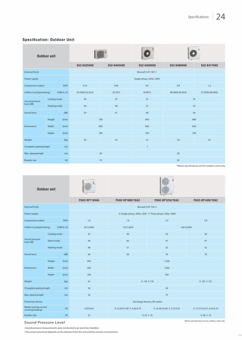
SUZ-KA25VAD SUZ-KA35VAD SUZ-KA50VAD SUZ-KA60VAD SUZ-KA71VAD
Specification: Outdoor Unit
Outdoor unit
Power supply
Compressor output
Airflow (cooling/heating)
Cooling mode
Heating mode
Height
Width
Depth
Sound pressurelevel (dB)
Sound level
Dimensions
Weight
Chargeless piping length
Max. piping length
Breaker size
(mm)
(mm)
(mm)
(kW)
CMM (L /S)
(dB)
(kg)
(m)
(m)
(A)
*Above specifications are for outdoor units only.
PUHZ-RP71VHA5 PUHZ-RP100V/YKA2 PUHZ-RP125V/YKA2 PUHZ-RP140V/YKA2
Munsell 3.0Y 7.8/1.1
V: Single-phase, 50Hz, 230V Y: Three-phase, 50Hz, 400V
1.6 1.9 2.4 2.9
60 (1,000) 110 (1,830)
49
120 (2,000)
47
46
50 50
44
51
47 47
48
69
52 52
7066 70
943 1,338
950
330
1,050
330
67 V: 118 Y: 119 V: 120 Y: 121
30 30
50 75
Discharge thermo, HP switch
9.05/9.64 V: 12.64/13.58 Y: 4.42/4.75 V: 16.36/16.90 Y: 5.73/5.91
V: 32 Y: 16
V: 17.17/19.23 Y: 6.01/6.73
25 V: 40 Y: 16
Outdoor unit
Power supply
Compressor output
Airflow (cooling/heating)
Cooling mode
Heating mode
Height
Width
Depth
Sound pressurelevel (dB)
Sound level
Dimensions
Weight
Chargeless piping length
Max. piping length
Protection device
(mm)
(mm)
(mm)
(kW)
CMM (L /S)
(dB)
(kg)
(m)
(m)
Silent mode
Rated running current(cooling/heating)
(A)
Breaker size (A)
External finish
External finish Munsell 3.0Y 7.8/1.1
Single-phase, 50Hz, 230V
0.55 0.65 0.9 1.2
34 (568)/32 (534) 33 (551) 49 (817) 57 (950)/48 (800)
46 47 53
46 48 55
59 61 68
550 850
800 840
285 330
30 33 53
0.9
58 (960)/49 (816)
55
55
69
880
840
330
50 53
7
20 30
10 20
Sound Pressure Level• Sound pressure measurements were conducted in an anechoic chamber.
• The actual noise level depends on the distance from the unit and the acoustic environment.
25 Specifications
*Above specifications are for outdoor units only.
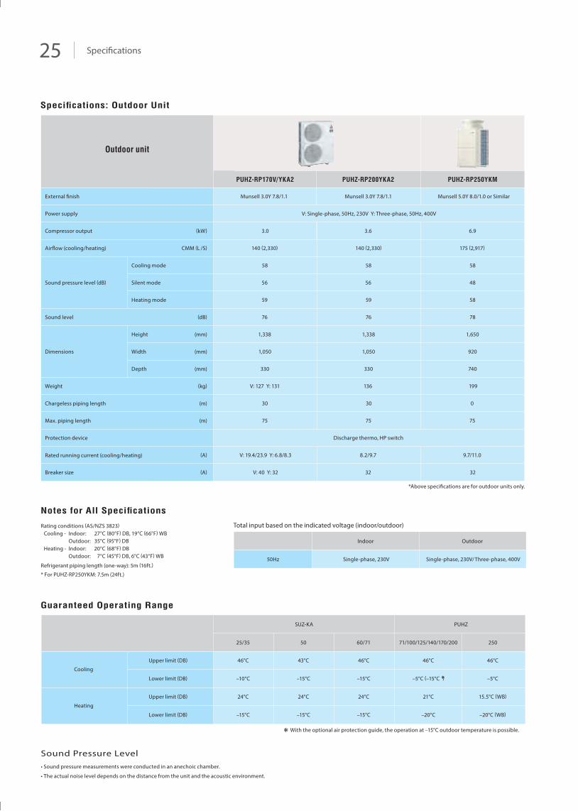
PUHZ-RP170V/YKA2 PUHZ-RP200YKA2 PUHZ-RP250YKM
Outdoor unit
Power supply
Compressor output
Airflow (cooling/heating)
Cooling mode
Heating mode
Height
Width
Depth
Sound pressure level (dB)
Sound level
Dimensions
Weight
Chargeless piping length
Max. piping length
Protection device
Rated running current (cooling/heating)
(mm)
(mm)
(mm)
(kW)
CMM (L /S)
(dB)
(kg)
(m)
(m)
Silent mode
(A)
Breaker size (A)
External finish Munsell 3.0Y 7.8/1.1 Munsell 3.0Y 7.8/1.1 Munsell 5.0Y 8.0/1.0 or Similar
V: Single-phase, 50Hz, 230V Y: Three-phase, 50Hz, 400V
3.0 3.6 6.9
140 (2,330) 140 (2,330) 175 (2,917)
58 5858
56 56 48
59 59 58
76 76 78
1,338 1,338 1,650
1,050 1,050 920
330 330 740
V: 127 Y: 131 136 199
30 30 0
75 7575
Discharge thermo, HP switch
V: 19.4/23.9 Y: 6.8/8.3 8.2/9.7 9.7/11.0
V: 40 Y: 32 32 32
Single-phase, 230V/ Three-phase, 400VSingle-phase, 230V50Hz
With the optional air protection guide, the operation at –15°C outdoor temperature is possible.
SUZ-KA
Upper limit (DB)
Lower limit (DB)
Upper limit (DB)
Lower limit (DB)
25/35
46°C
–10°C
24°C
–15°C
50
43°C
–15°C
24°C
–15°C
60/71
46°C
–15°C
24°C
–15°C
Heating
Cooling
PUHZ
46°C
–5°C
15.5°C (WB)
–20°C (WB)
25071/100/125/140/170/200
46°C
–5°C (–15°C )
21°C
–20°C
Notes for All Specifications
Rating conditions (AS/NZS 3823)Cooling - Indoor: 27°C (80°F) DB, 19°C (66°F) WB Outdoor: 35°C (95°F) DBHeating - Indoor: 20°C (68°F) DB Outdoor: 7°C (45°F) DB, 6°C (43°F) WB
Refrigerant piping length (one-way): 5m (16ft.)
* For PUHZ-RP250YKM: 7.5m (24ft.)
Total input based on the indicated voltage (indoor/outdoor)
Indoor Outdoor
Guaranteed Operating Range
Specifications: Outdoor Unit
Sound Pressure Level• Sound pressure measurements were conducted in an anechoic chamber.
• The actual noise level depends on the distance from the unit and the acoustic environment.
Optional Parts 26
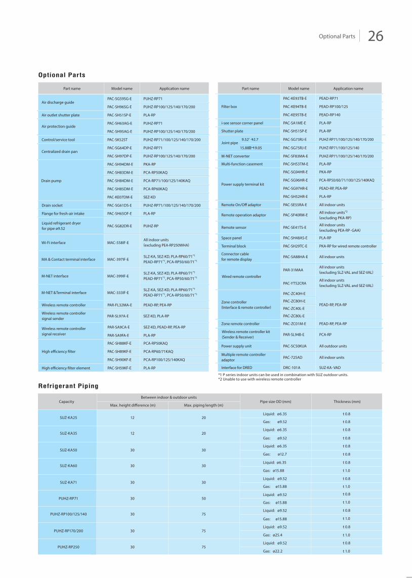
*1 P series indoor units can be used in combination with SUZ outdoor units.*2 Unable to use with wireless remote controller
Optional Parts
Refrigerant Piping
Part name Model name Application name
PUHZ-RP71PAC-SG59SG-E
PUHZ-RP100/125/140/170/200PAC-SH96SG-E
PLA-RPPAC-SH51SP-EAir outlet shutter plate
Air discharge guide
PUHZ-RP71PAC-SH63AG-E
PUHZ-RP100/125/140/170/200PAC-SH95AG-EAir protection guide
PUHZ-RP71/100/125/140/170/200PAC-SK52STControl/service tool
PUHZ-RP71PAC-SG64DP-E
PUHZ-RP100/125/140/170/200PAC-SH97DP-E
PKA-RPPAC-SH94DM-E
PCA-RP50KAQPAC-SH83DM-E
PCA-RP71/100/125/140KAQPAC-SH84DM-EDrain pump
PCA-RP60KAQPAC-SH85DM-E
SEZ-KDPAC-KE07DM-E
PUHZ-RP71/100/125/140/170/200PAC-SG61DS-E
PLA-RPPAC-SH65OF-E
Drain socket
Flange for fresh-air intake
PUHZ-RPPAC-SG82DR-ELiquid refrigerant dryerfor pipe ø9.52
MAC-558IF-EWi-Fi interfaceAll indoor units(excluding PEA-RP250WHA)
MAC-399IF-EM-NET interfaceSLZ-KA, SEZ-KD, PLA-RP60/71*1
PEAD-RP71*1, PCA-RP50/60/71*1
MAC-397IF-EMA & Contact terminal interfaceSLZ-KA, SEZ-KD, PLA-RP60/71*1
PEAD-RP71*1, PCA-RP50/60/71*1
MAC-333IF-EM-NET &Terminal interfaceSLZ-KA, SEZ-KD, PLA-RP60/71*1
PEAD-RP71*1, PCA-RP50/60/71*1
Wireless remote controller PAR-FL32MA-E PEAD-RP, PEA-RP
High efficiency filter element PAC-SH59KF-E PLA-RP
Wireless remote controllersignal receiver
PAR-SA9CA-E SEZ-KD, PEAD-RP, PEA-RP
PAR-SA9FA-E PLA-RP
PAR-SL97A-E SEZ-KD, PLA-RPWireless remote controllersignal sender
Centralized drain pan
SUZ-KA25
SUZ-KA35
12
12
20
20
SUZ-KA50
SUZ-KA60
30
30
30
30
Liquid: ø6.35
Gas: ø9.52
Liquid: ø6.35
Gas: ø9.52
Liquid: ø6.35
SUZ-KA71 30 30Gas: ø15.88
Liquid: ø9.52
Gas: ø12.7
Liquid: ø6.35
Gas: ø15.88
t 0.8
t 0.8
t 0.8
t 0.8
t 0.8
t 0.8
t 0.8
t 1.0
PUHZ-RP71
PUHZ-RP100/125/140
30
30
50
75
PUHZ-RP170/200 30 75Liquid: ø9.52
Gas: ø15.88
t 0.8
t 1.0
t 0.8
t 1.0
t 0.8
t 1.0
Liquid: ø9.52
Gas: ø15.88
Liquid: ø9.52
Gas: ø25.4
Thickness (mm)Pipe size OD (mm)CapacityBetween indoor & outdoor units
Max. height difference (m) Max. piping length (m)
t 1.0
t 0.8
Part name
PLA-RPPAC-SH51SP-EShutter plate
PLA-RPPAC-SA1ME-Ei-see sensor corner panel
PEAD-RP140PAC-KE95TB-E
PEAD-RP100/125PAC-KE94TB-EFilter box
PEAD-RP71PAC-KE93TB-E
PUHZ-RP71/100/125/140/170/200
PUHZ-RP71/100/125/140
PAC-SG73RJ-E
PAC-SG75RJ-EJoint pipe
9.52‘ 12.7
15.88� 19.05
PUHZ-RP71/100/125/140/170/200PAC-SF83MA-EM-NET converter
PLA-RPPAC-SH53TM-E
PKA-RPPAC-SG94HR-E
PCA-RP50/60/71/100/125/140KAQPAC-SG96HR-EPower supply terminal kit
PEAD-RP, PEA-RPPAC-SG97HR-E
PLA-RPPAC-SH52HR-E
All indoor unitsPAC-SE55RA-E
All indoor units*2
(excluding PKA-RP)PAC-SF40RM-E
All indoor units(excluding PEA-RP • GAA)
PAC-SE41TS-E
PLA-RPPAC-SH48AS-E
PKA-RP for wired remote controllerPAC-SH29TC-E
Remote On/Off adaptor
Remote operation adaptor
Remote sensor
Space panel
Terminal block
All indoor unitsPAC-SA88HA-EConnector cablefor remote display
All outdoor unitsPAC-SC50KUAPower supply unit
PAC-ZC40H-E
PEAD-RP, PEA-RPPAC-ZC80H-EZone controller
(Interface & remote controller) PAC-ZC40L-E
PAC-ZC80L-E
PEAD-RP, PEA-RPPAC-ZC01M-EZone remote controller
SUZ-KA • VADDRC-101AInterface for DRED
All indoor unitsPAC-725ADMultiple remote controlleradaptor
All indoor units(excluding SLZ-VAL and SEZ-VAL)PAR-31MAA
All indoor units(excluding SLZ-VAL and SEZ-VAL)PAC-YT52CRA
PCA-RPWireless remote controller kit(Sender & Receiver)
Wired remote controller
PAR-SL94B-E
Multi-function casement
Model name Application name
PCA-RP50KAQPAC-SH88KF-E
PCA-RP60/71KAQPAC-SH89KF-EHigh efficiency filter
PCA-RP100/125/140KAQPAC-SH90KF-E
PUHZ-RP250 30 75Liquid: ø9.52 t 0.8
t 1.0Gas: ø22.2
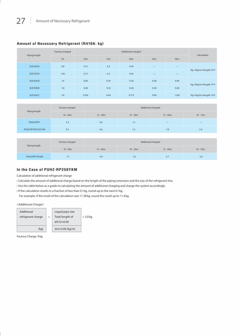
27 Amount of Necessary Refrigerant
Amount of Necessary Refrigerant (R410A: kg)
PUHZ-RP71
PUHZ-RP100/125/140
PUHZ-RP170/200 7.7 0.9 1.8 2.7 3.6
61 - 70m
SUZ-KA25
SUZ-KA35
SUZ-KA50
SUZ-KA60
SUZ-KA71
0.8
1.05
1.6
1.8
1.8
0.15
0.15
0.06
0.06
0.165
0.3
0.3
0.16
0.16
0.44
0.45
0.45
0.26
0.26
0.715
—
—
0.36
0.36
0.99
—
—
0.46
0.46
1.265
Xg = 30g/m × (length-5) m
Xg = 20g/m × (length-7) m
Xg = 55g/m × (length-7) m
30m25m20m15m10m7m
Factory charged Additional chargedCalculationPiping length
Piping length
Piping length
Factory charged Additional charged
Factory charged Additional charged
3.5
5.5
10 - 30m
0.6
0.6
31 - 40m
1.2
1.2
41 - 50m
—
1.8
51 - 60m
—
2.4
61 - 75m
51 - 60m41 - 50m31 - 40m10 - 30m
In the Case of PUHZ-RP250YKM
Calculation of additional refrigerant charge
• Calculate the amount of additional charge based on the length of the piping extension and the size of the refrigerant line.
• Use the table below as a guide to calculating the amount of additional charging and charge the system accordingly.
• If the calculation results in a fraction of less than 0.1kg, round up to the next 0.1kg.
For example, if the result of the calculation was 11.38 kg, round the result up to 11.4 kg.
<Additional Charge>
Factory Charge: 9 kg
Additional
refrigerant charge
Liquid pipe size
Total length of
ø9.52×0.06
(kg)
= + 3.0 kg
(m)×0.06 (kg/m)
28
NOTICE
* Air conditioners in this brochure contain and operate with refrigerant R410A and synthetic oils.Before attempting any installation work you must read the installation instructions.New tools, materials and procedures are required to install these products.Under Australian Law, only persons suitably licensed are permitted to install and service air conditioning units. The buyer must ensure that the person and/or company who is install, service or repair the air conditioner has the necessary licences, qualifications and experience to perform the work. Suitable access for warranty and service is required. Refer to conditions of warranty on the Mitsubishi Electric website. For future improvement, specifications, designs of product and availability are subject to change without notice. Refer to Country, Commonwealth, State or Territory legislation, regulations and industry codes of practice, before installation of these products.Recovery and disposal of waste material must comply with Country, Commonwealth, State or Territory guidelines.
* Do not install indoor units in areas (e.g., mobile phone base stations) where the emission of VOCs such as phthalate compounds and formaldehyde is known to be high as this may result in a chemical reaction.
* When installing or relocating or servicing the air conditioners, use only the specified refrigerant (R410A) to charge the refrigerant lines.Do not mix it with any other refrigerant and do not allow air to remain in the lines.If air is mixed with the refrigerant, then it can be the cause of abnormal high pressure in the refrigerant lines, and may result in an explosion and other hazards.The use of any refrigerant other than that specified for the system will cause mechanical failure or system malfunction or unit breakdown. In the worst case, this may lead to a serious impediment to securing product safety.
* Specifications, designs and other content appearing in this brochure are current as at January 2015 and are subject to change without notice. Diagrams are representations for illustrative purposes only.
Simply contact your nearest Mitsubishi Electric Specialist today and you can find out all there is to know about how to enhance your living environment. Our specialists are fully qualified to give you all the right advice on which Mitsubishi Electric Air Conditioning System is right for you.
To locate your nearest Mitsubishi Electric Specialist go to our website
www.MitsubishiElectric.com.auThey will determine whether a Compact Inverter System or a Power Inverter System best suits your needs, both in comfort and efficiency. You can either visit one of our Specialist’s Showrooms, or they will happily arrange for one of their Consultants to come to your home.
All Mitsubishi Electric Compact and Power Inverter Systems are MEPS (Minimum Energy Performance Standards) Compliant, so you can be sure that they will give you the performance and efficiency that they were designed to deliver.
Warm, even heat in winter and cool,comfort in summer is only a phonecall or click away.
L-179-7-C7654-K 1412
Revised publication, effective March. 2015Superseding publication L-179-7-C7654-J Jul. 2014
www.MitsubishiElectric.com.au
1300 722 228
Specifications, designs and other content appearing in this brochure are current as at the time of printing and are subject to change without notice. Diagrams are representation for illustrative purposes only.