Embed Size (px)
Citation preview
Manufacturer reserves the right to discontinue, or change at any time, specifications or designs without notice and without incurring obligations.PC 903 Catalog No. 533-00025 Printed in U.S.A. Form 30RA-7SI Pg 1 8-01 Replaces: NewBook 2
Tab 5c
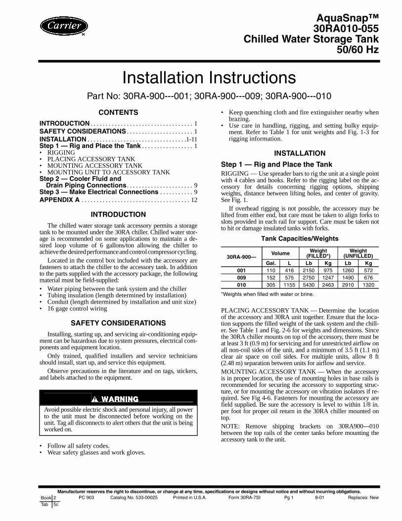
Installation InstructionsPart No: 30RA-900---001; 30RA-900---009; 30RA-900---010
CONTENTS
INTRODUCTION . . . . . . . . . . . . . . . . . . . . . . . . . . . . . . . . . . 1SAFETY CONSIDERATIONS . . . . . . . . . . . . . . . . . . . . . . 1INSTALLATION . . . . . . . . . . . . . . . . . . . . . . . . . . . . . . . . .1-11Step 1 — Rig and Place the Tank . . . . . . . . . . . . . . . . . 1• RIGGING• PLACING ACCESSORY TANK• MOUNTING ACCESSORY TANK• MOUNTING UNIT TO ACCESSORY TANKStep 2 — Cooler Fluid and
Drain Piping Connections . . . . . . . . . . . . . . . . . . . . . . 9Step 3 — Make Electrical Connections . . . . . . . . . . . 9APPENDIX A . . . . . . . . . . . . . . . . . . . . . . . . . . . . . . . . . . . . 12
INTRODUCTION
The chilled water storage tank accessory permits a storagetank to be mounted under the 30RA chiller. Chilled water stor-age is recommended on some applications to maintain a de-sired loop volume of 6 gallons/ton allowing the chiller toachieve the desired performance and control compressor cycling.
Located in the control box included with the accessory arefasteners to attach the chiller to the accessory tank. In additionto the parts supplied with the accessory package, the followingmaterial must be field-supplied:• Water piping between the tank system and the chiller• Tubing insulation (length determined by installation)• Conduit (length determined by installation and unit size)• 16 gage control wiring
SAFETY CONSIDERATIONS
Installing, starting up, and servicing air-conditioning equip-ment can be hazardous due to system pressures, electrical com-ponents and equipment location.
Only trained, qualified installers and service techniciansshould install, start up, and service this equipment.
Observe precautions in the literature and on tags, stickers,and labels attached to the equipment.
• Follow all safety codes.• Wear safety glasses and work gloves.
• Keep quenching cloth and fire extinguisher nearby whenbrazing.
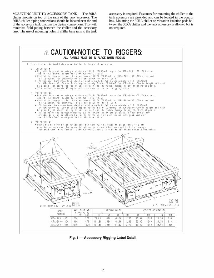
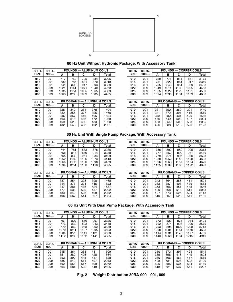
• Use care in handling, rigging, and setting bulky equip-ment. Refer to Table 1 for unit weights and Fig. 1-3 forrigging information.
INSTALLATION
Step 1 — Rig and Place the TankRIGGING — Use spreader bars to rig the unit at a single pointwith 4 cables and hooks. Refer to the rigging label on the ac-cessory for details concerning rigging options, shippingweights, distance between lifting holes, and center of gravity.See Fig. 1.
If overhead rigging is not possible, the accessory may belifted from either end, but care must be taken to align forks toslots provided in each rail for support. Care must be taken notto hit or damage insulated tanks with forks.
Tank Capacities/Weights
*Weights when filled with water or brine.
PLACING ACCESSORY TANK — Determine the locationof the accessory and 30RA unit together. Ensure that the loca-tion supports the filled weight of the tank system and the chill-er. See Table 1 and Fig. 2-6 for weights and dimensions. Sincethe 30RA chiller mounts on top of the accessory, there must beat least 3 ft (0.9 m) for servicing and for unrestricted airflow onall non-coil sides of the unit, and a minimum of 3.5 ft (1.1 m)clear air space on coil sides. For multiple units, allow 8 ft(2.48 m) separation between units for airflow and service.MOUNTING ACCESSORY TANK — When the accessoryis in proper location, the use of mounting holes in base rails isrecommended for securing the accessory to supporting struc-ture, or for mounting the accessory on vibration isolators if re-quired. See Fig 4-6. Fasteners for mounting the accessory arefield supplied. Be sure the accessory is level to within 1/8 in.per foot for proper oil return in the 30RA chiller mounted ontop.NOTE: Remove shipping brackets on 30RA900---010between the top rails of the center tanks before mounting theaccessory tank to the unit.
Avoid possible electric shock and personal injury, all powerto the unit must be disconnected before working on theunit. Tag all disconnects to alert others that the unit is beingworked on.
30RA-900---Volume Weight
(FILLED*)Weight
(UNFILLED)Gal. L Lb Kg Lb Kg
001 110 416 2150 975 1260 572009 152 575 2750 1247 1490 676010 305 1155 5430 2463 2910 1320
AquaSnap™30RA010-055
Chilled Water Storage Tank50/60 Hz
2
MOUNTING UNIT TO ACCESSORY TANK — The 30RAchiller mounts on top of the rails of the tank accessory. The30RA chiller piping connections should be located near the endof the accessory tank that has the piping connections. This willminimize field piping between the chiller and the accessorytank. The use of mounting holes in chiller base rails to the tank
accessory is required. Fasteners for mounting the chiller to thetank accessory are provided and can be located in the controlbox. Mounting the 30RA chiller on vibration isolation pads be-tween the 30RA chiller and the tank accessory is allowed but isnot required.
Fig. 1 — Accessory Rigging Label Detail
3
60 Hz Unit Without Hydronic Package, With Accessory Tank
60 Hz Unit With Single Pump Package, With Accessory Tank
60 Hz Unit With Dual Pump Package, With Accessory Tank
Fig. 2 — Weight Distribution 30RA-900---001, 009
30RASIZE
30RA-900---
POUNDS — ALUMINUM COILS 30RASIZE
30RA-900---
POUNDS — COPPER COILSA B C D Total A B C D Total
010 001 717 750 795 834 3096 010 001 729 771 814 861 3175015 001 732 785 831 870 3218 015 001 751 820 861 917 3349018 001 741 808 917 893 3359 018 001 755 843 951 939 3488022 009 1021 1141 1071 1040 4273 022 009 1049 1211 1108 1095 4463025 009 1035 1154 1085 1065 4339 025 009 1065 1222 1122 1121 4530030 009 1063 1208 1099 1085 4455 030 009 1094 1296 1131 1159 4680
30RASIZE
30RA-900---
KILOGRAMS — ALUMINUM COILS 30RASIZE
30RA-900---
KILOGRAMS — COPPER COILSA B C D Total A B C D Total
010 001 325 340 361 378 1404 010 001 331 350 369 391 1440015 001 332 356 377 395 1460 015 001 341 372 391 416 1519018 001 336 367 416 405 1524 018 001 342 382 431 426 1582022 009 463 518 486 472 1938 022 009 476 549 503 497 2024025 009 469 523 492 483 1968 025 009 483 554 509 508 2055030 009 482 548 498 492 2021 030 009 496 588 513 526 2123
30RASIZE
30RA-900---
POUNDS — ALUMINUM COILS 30RASIZE
30RA-900---
POUNDS — COPPER COILSA B C D Total A B C D Total
010 001 744 781 833 878 3236 010 001 756 802 852 905 3315015 001 758 817 869 914 3358 015 001 777 852 899 961 3489018 001 765 839 961 934 3499 018 001 779 874 995 980 3628022 009 1052 1182 1106 1073 4413 022 009 1080 1252 1143 1128 4603025 009 1066 1195 1120 1098 4479 025 009 1096 1263 1157 1154 4670030 009 1094 1251 1133 1118 4595 030 009 1125 1339 1165 1192 4820
30RASIZE
30RA-900---
KILOGRAMS — ALUMINUM COILS 30RASIZE
30RA-900---
KILOGRAMS — COPPER COILSA B C D Total A B C D Total
010 001 337 354 378 398 1468 010 001 343 364 386 411 1504015 001 344 371 394 415 1523 015 001 352 387 408 436 1583018 001 347 381 436 424 1587 018 001 353 396 451 445 1646022 009 477 536 502 487 2002 022 009 490 568 518 511 2088025 009 483 542 508 498 2032 025 009 497 573 525 524 2118030 009 496 567 514 507 2084 030 009 510 607 528 541 2186
30RASIZE
30RA-900---
POUNDS — ALUMINUM COILS 30RASIZE
30RA-900---
POUNDS — COPPER COILSA B C D Total A B C D Total
010 001 761 802 856 907 3326 010 001 773 823 875 934 3405015 001 773 839 893 943 3448 015 001 792 874 923 990 3579018 001 779 860 988 962 3589 018 001 793 895 1022 1008 3718022 009 1070 1211 1127 1095 4503 022 009 1098 1281 1164 1150 4693025 009 1084 1223 1141 1121 4569 025 009 1114 1291 1178 1177 4760030 009 1112 1280 1152 1141 4685 030 009 1143 1368 1184 1215 4910
30RASIZE
30RA-900---
KILOGRAMS — ALUMINUM COILS 30RASIZE
30RA-900---
KILOGRAMS — COPPER COILSA B C D Total A B C D Total
010 001 345 364 388 411 1509 010 001 350 373 397 424 1544015 001 351 380 405 428 1564 015 001 359 396 418 449 1623018 001 353 390 448 437 1628 018 001 360 406 463 457 1686022 009 485 549 511 497 2043 022 009 498 581 528 522 2129025 009 492 555 517 509 2072 025 009 505 585 534 534 2159030 009 504 581 522 518 2125 030 009 518 621 537 551 2227
B
C
A
D
CONTROLBOX END
4
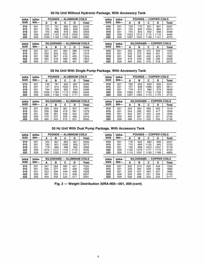
50 Hz Unit Without Hydronic Package, With Accessory Tank
50 Hz Unit With Single Pump Package, With Accessory Tank
50 Hz Unit With Dual Pump Package, With Accessory Tank
Fig. 2 — Weight Distribution 30RA-900---001, 009 (cont)
30RASIZE
30RA-900---
POUNDS — ALUMINUM COILS 30RASIZE
30RA-900---
POUNDS — COPPER COILSA B C D Total A B C D Total
010 001 721 751 802 852 3126 010 001 733 772 821 881 3207015 001 725 782 996 839 3342 015 001 735 820 1034 884 3473018 001 740 808 918 893 3359 018 001 754 844 952 938 3488022 009 1025 1143 1078 1059 4305 022 009 1053 1210 1115 1116 4494025 009 1039 1158 1100 1083 4380 025 009 1067 1224 1138 1141 4570
30RASIZE
30RA-900---
KILOGRAMS — ALUMINUM COILS 30RASIZE
30RA-900---
KILOGRAMS — COPPER COILSA B C D Total A B C D Total
010 001 327 341 364 386 1418 010 001 332 350 372 400 1455015 001 329 355 452 381 1516 015 001 333 372 469 401 1575018 001 336 367 416 405 1524 018 001 342 383 432 425 1582022 009 465 518 489 480 1953 022 009 478 549 506 506 2038025 009 471 525 499 491 1987 025 009 484 555 516 518 2073
30RASIZE
30RA-900---
POUNDS — ALUMINUM COILS 30RASIZE
30RA-900---
POUNDS — COPPER COILSA B C D Total A B C D Total
010 001 748 781 840 897 3266 010 001 760 802 859 926 3347015 001 747 810 1050 875 3482 015 001 757 848 1088 920 3613018 001 764 839 962 934 3499 018 001 778 875 996 979 3628022 009 1056 1184 1113 1093 4445 022 009 1084 1251 1150 1150 4634025 009 1069 1198 1135 1117 4520 025 009 1097 1264 1173 1175 4710
30RASIZE
30RA-900---
KILOGRAMS — ALUMINUM COILS 30RASIZE
30RA-900---
KILOGRAMS — COPPER COILSA B C D Total A B C D Total
010 001 339 354 381 407 1481 010 001 345 364 389 420 1518015 001 339 368 476 397 1579 015 001 344 385 493 417 1639018 001 346 381 436 424 1587 018 001 353 397 452 444 1646022 009 479 537 505 496 2016 022 009 492 567 522 521 2102025 009 485 543 515 507 2050 025 009 498 573 532 533 2136
30RASIZE
30RA-900---
POUNDS — ALUMINUM COILS 30RASIZE
30RA-900---
POUNDS — COPPER COILSA B C D Total A B C D Total
010 001 764 801 863 927 3356 010 001 776 822 882 956 3437015 001 760 831 1082 900 3572 015 001 770 869 1120 945 3703018 001 778 860 989 962 3589 018 001 792 896 1023 1007 3718022 009 1074 1212 1134 1116 4535 022 009 1102 1279 1171 1173 4724025 009 1087 1225 1157 1141 4610 025 009 1115 1291 1195 1199 4800
30RASIZE
30RA-900---
KILOGRAMS — ALUMINUM COILS 30RASIZE
30RA-900---
KILOGRAMS — COPPER COILSA B C D Total A B C D Total
010 001 347 364 392 421 1522 010 001 352 373 400 434 1559015 001 345 377 491 408 1620 015 001 349 394 508 428 1680018 001 353 390 449 436 1628 018 001 359 407 464 457 1686022 009 487 550 514 506 2057 022 009 500 580 531 532 2143025 009 493 556 525 517 2091 025 009 506 586 542 544 2177
5
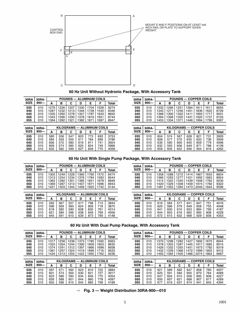
60 Hz Unit Without Hydronic Package, With Accessory Tank
60 Hz Unit With Single Pump Package, With Accessory Tank
60 Hz Unit With Dual Pump Package, With Accessory Tank
Fig. 3 — Weight Distribution 30RA-900---010
30RASIZE
30RA-900---
POUNDS — ALUMINUM COILS 30RASIZE
30RA-900---
POUNDS — COPPER COILSA B C D E F Total A B C D E F Total
035 010 1279 1226 1207 1330 1704 1528 8274 035 010 1332 1266 1251 1384 1811 1611 8655040 010 1287 1232 1213 1346 1728 1540 8346 040 010 1340 1271 1256 1401 1836 1622 8726045 010 1335 1260 1278 1357 1787 1633 8650 045 010 1388 1300 1322 1411 1893 1717 9031050 010 1343 1266 1290 1378 1816 1651 8744 050 010 1394 1308 1335 1431 1920 1737 9125055 010 1394 1282 1321 1382 1871 1697 8947 055 010 1453 1334 1371 1446 1994 1799 9397
30RASIZE
30RA-900---
KILOGRAMS — ALUMINUM COILS 30RASIZE
30RA-900---
KILOGRAMS — COPPER COILSA B C D E F Total A B C D E F Total
035 010 580 556 547 603 773 693 3753 035 010 604 574 567 628 821 731 3926040 010 584 559 550 611 784 699 3786 040 010 608 577 570 635 833 736 3958045 010 606 572 580 616 811 741 3924 045 010 630 590 600 640 859 779 4096050 010 609 574 585 625 824 749 3966 050 010 632 593 606 649 871 788 4139055 010 632 582 599 627 849 770 4058 055 010 659 605 622 656 904 816 4262
30RASIZE
30RA-900---
POUNDS — ALUMINUM COILS 30RASIZE
30RA-900---
POUNDS — COPPER COILSA B C D E F Total A B C D E F Total
035 010 1305 1249 1228 1360 1760 1572 8474 035 010 1358 1288 1272 1414 1867 1655 8854040 010 1313 1254 1234 1376 1784 1583 8544 040 010 1366 1293 1277 1431 1892 1665 8924045 010 1362 1282 1301 1385 1841 1678 8849 045 010 1414 1322 1345 1439 1948 1762 9230050 010 1369 1287 1313 1407 1871 1696 8943 050 010 1420 1329 1358 1459 1974 1782 9322055 010 1421 1303 1344 1409 1925 1742 9144 055 010 1481 1355 1394 1473 2049 1844 9596
30RASIZE
30RA-900---
KILOGRAMS — ALUMINUM COILS 30RASIZE
30RA-900---
KILOGRAMS — COPPER COILSA B C D E F Total A B C D E F Total
035 010 592 567 557 617 798 713 3844 035 010 616 584 577 641 847 751 4016040 010 596 569 560 624 809 718 3875 040 010 620 586 579 649 858 755 4048045 010 618 582 590 628 835 761 4014 045 010 641 600 610 653 884 799 4187050 010 621 584 596 638 849 769 4056 050 010 644 603 616 662 895 808 4228055 010 645 591 610 639 873 790 4148 055 010 672 615 632 668 929 836 4353
30RASIZE
30RA-900---
POUNDS — ALUMINUM COILS 30RASIZE
30RA-900---
POUNDS — COPPER COILSA B C D E F Total A B C D E F Total
035 010 1317 1258 1238 1373 1785 1592 8563 035 010 1370 1298 1282 1427 1892 1675 8944040 010 1325 1264 1244 1390 1809 1603 8635 040 010 1378 1303 1287 1445 1917 1685 9015045 010 1374 1291 1312 1397 1866 1698 8938 045 010 1426 1332 1355 1451 1973 1782 9319050 010 1381 1297 1324 1419 1896 1716 9033 050 010 1432 1339 1368 1472 1999 1802 9412055 010 1434 1313 1355 1422 1950 1762 9236 055 010 1493 1365 1405 1486 2074 1864 9687
30RASIZE
30RA-900---
KILOGRAMS — ALUMINUM COILS 30RASIZE
30RA-900---
KILOGRAMS — COPPER COILSA B C D E F Total A B C D E F Total
035 010 597 571 562 623 810 722 3884 035 010 621 589 582 647 858 760 4057040 010 601 573 564 630 821 727 3917 040 010 625 591 584 655 870 764 4089045 010 623 586 595 634 846 770 4054 045 010 647 604 615 658 895 808 4227050 010 626 588 601 644 860 778 4097 050 010 650 607 621 668 907 817 4269055 010 650 596 615 645 885 799 4189 055 010 677 619 637 674 941 845 4394
CONTROLBOX END
B
C
F
D
E
A
46
MOUNT E AND F POSITIONS ON AT LEAST 4x6INCH RAIL OR PLATE TO SUPPORT GIVENWEIGHT.
→
1001
6
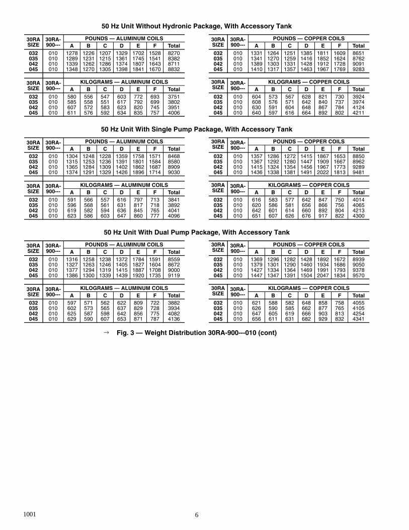
50 Hz Unit Without Hydronic Package, With Accessory Tank
50 Hz Unit With Single Pump Package, With Accessory Tank
50 Hz Unit With Dual Pump Package, With Accessory Tank
Fig. 3 — Weight Distribution 30RA-900---010 (cont)
30RASIZE
30RA-900---
POUNDS — ALUMINUM COILS 30RASIZE
30RA-900---
POUNDS — COPPER COILSA B C D E F Total A B C D E F Total
032 010 1278 1226 1207 1329 1702 1528 8270 032 010 1331 1264 1251 1385 1811 1609 8651035 010 1289 1231 1215 1361 1745 1541 8382 035 010 1341 1270 1259 1416 1852 1624 8762042 010 1339 1262 1286 1374 1807 1643 8711 042 010 1389 1303 1331 1428 1912 1728 9091045 010 1348 1270 1305 1398 1841 1670 8832 045 010 1410 1317 1357 1463 1967 1769 9283
30RASIZE
30RA-900---
KILOGRAMS — ALUMINUM COILS 30RASIZE
30RA-900---
KILOGRAMS — COPPER COILSA B C D E F Total A B C D E F Total
032 010 580 556 547 603 772 693 3751 032 010 604 573 567 628 821 730 3924035 010 585 558 551 617 792 699 3802 035 010 608 576 571 642 840 737 3974042 010 607 572 583 623 820 745 3951 042 010 630 591 604 648 867 784 4124045 010 611 576 592 634 835 757 4006 045 010 640 597 616 664 892 802 4211
30RASIZE
30RA-900---
POUNDS — ALUMINUM COILS 30RASIZE
30RA-900---
POUNDS — COPPER COILSA B C D E F Total A B C D E F Total
032 010 1304 1248 1228 1359 1758 1571 8468 032 010 1357 1286 1272 1415 1867 1653 8850035 010 1315 1253 1236 1391 1801 1584 8580 035 010 1367 1292 1280 1447 1909 1667 8962042 010 1365 1284 1309 1402 1862 1687 8909 042 010 1415 1324 1354 1456 1967 1773 9289045 010 1374 1291 1329 1426 1896 1714 9030 045 010 1436 1338 1381 1491 2022 1813 9481
30RASIZE
30RA-900---
KILOGRAMS — ALUMINUM COILS 30RASIZE
30RA-900---
KILOGRAMS — COPPER COILSA B C D E F Total A B C D E F Total
032 010 591 566 557 616 797 713 3841 032 010 616 583 577 642 847 750 4014035 010 596 568 561 631 817 718 3892 035 010 620 586 581 656 866 756 4065042 010 619 582 594 636 845 765 4041 042 010 642 601 614 660 892 804 4213045 010 623 586 603 647 860 777 4096 045 010 651 607 626 676 917 822 4300
30RASIZE
30RA-900---
POUNDS — ALUMINUM COILS 30RASIZE
30RA-900---
POUNDS — COPPER COILSA B C D E F Total A B C D E F Total
032 010 1316 1258 1238 1372 1784 1591 8559 032 010 1369 1296 1282 1428 1892 1672 8939035 010 1327 1263 1246 1405 1827 1604 8672 035 010 1379 1301 1290 1460 1934 1686 9050042 010 1377 1294 1319 1415 1887 1708 9000 042 010 1427 1334 1364 1469 1991 1793 9378045 010 1386 1300 1339 1439 1920 1735 9119 045 010 1447 1347 1391 1504 2047 1834 9570
30RASIZE
30RA-900---
KILOGRAMS — ALUMINUM COILS 30RASIZE
30RA-900---
KILOGRAMS — COPPER COILSA B C D E F Total A B C D E F Total
032 010 597 571 562 622 809 722 3882 032 010 621 588 582 648 858 758 4055035 010 602 573 565 637 829 728 3934 035 010 626 590 585 662 877 765 4105042 010 625 587 598 642 856 775 4082 042 010 647 605 619 666 903 813 4254045 010 629 590 607 653 871 787 4136 045 010 656 611 631 682 929 832 4341
→
1001
7
TANKACCESS
TANK ACCESS TANK ACCESSTANK ACCESS
CONTROLBOX
TANK ACCESS TANK ACCESS
CONTROLBOX END
CONTROLBOX
TANK ACCESS
TANKACCESS
TANKACCESS
MOUNTING HOLES, MIDDLE,EACH SIDE .395/.405 DIA. (TYP)
MOUNTING HOLES,FOUR CORNERS (TYP)
3” (76.2mm)
2.5” (63.5mm) FPT WATERINLET/OUTLET
2.5” (63.5mm) FPT WATERINLET/OUTLET
C.B.ACCESS
6’-10 51/64”(2103mm)
2’-21/64”(618mm)CENTEROFGRAVITY
1’-1/2”(306mm)
1’-1/2”(306mm)
1’-5 31/64”(444mm)
1’-5 31/64”(444mm)
1’-11”(584mm)
.88” (22.35mm) KNOCKOUTFOR POWER TO CONTROL BOX
1.50”(38.1mm)
3’-4 5/16”(1024mm)CENTER
OFGRAVITY
4’-21/32”(1236mm)
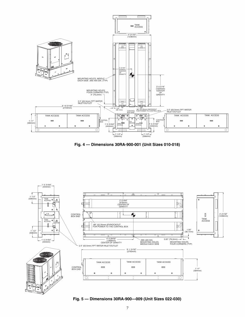
Fig. 4 — Dimensions 30RA-900-001 (Unit Sizes 010-018)
CONTROLBOX END
2’-21/64”(618mm)
CENTER OFGRAVITY
TANKACCESS
TANKACCESS
C.B.ACCESS
TANKACCESS
1’-1/2”(306mm)
1’-5 31/64”(444mm)
4’-21/32”(1236mm)
CONTROLBOX END
1’-1/2”(306mm)
1’-5 31/64”(444mm)
TANK ACCESSTANK ACCESSTANK ACCESS
2.5” (63.5mm) FPT WATER INLET/OUTLET
9’-1 31/32”(2793mm)
1’-11”(584mm)
4’-5 29/32”(1369mm)
CENTER OF GRAVITY.395/.405 DIA.MOUNTING HOLES,MIDDLE EACH SIDE
.88” (22.35mm) O KNOCKOUTFOR POWER TO THE CONTROL BOX
1.50”(38.1mm)
3.00” (76.2mm)MOUNTING HOLES,FOUR CORNERS (TYP)
Fig. 5 — Dimensions 30RA-900---009 (Unit Sizes 022-030)
8
TANKACCESS
C.B.ACCESS
4’-21/32”(1236mm)CENTER
OFGRAVITY
CONTROLBOX END
1’-1/2”(306mm)
1’-5 31/64”(444mm)
2.5” (63.5mm) FPT WATERINLET/OUTLET
4’-5 29/32”(1369mm)
CENTER OF GRAVITY
.395/.405 DIA.MOUNTING HOLES,MIDDLE EACH SIDE
1.50”(38.1mm)
3.00” (76.2mm)
MOUNTING HOLES,FOUR CORNERS (TYP)
CONTROLBOX END
TANKACCESS
TANKACCESS1’-1/2”
(306mm)
1’-5 31/64”(444mm)
TANKACCESS
MOUNTING HOLES
TANKACCESS
3’-9 21/32”
3’-9 21/32”
MOUNTINGHOLES
8’-1 21/64”(2472mm)
.88” (22.35mm) O KNOCKOUTFOR POWER TO THE CONTROL BOX
C.B.ACCESS
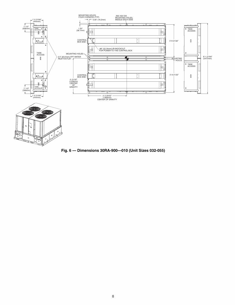
Fig. 6 — Dimensions 30RA-900---010 (Unit Sizes 032-055)
9
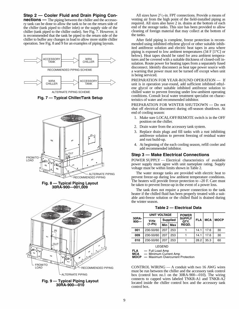
Step 2 — Cooler Fluid and Drain Piping Con-nections — The piping between the chiller and the accesso-ry tank can be done to allow the tank to be on the return side ofthe chiller (tank piped to chiller inlet) or the supply side of thechiller (tank piped to the chiller outlet). See Fig. 7. However, itis recommended that the tank be piped to the return side of thechiller to buffer any changes in load to allow more stable chilleroperation. See Fig. 8 and 9 for an examples of piping layouts.
All sizes have 21/2-in. FPT connections. Provide a means ofventing air from the high point of the field-installed piping asrequired. All sizes also have 2 in. drains at the bottom of eachend of the storage tanks. This size has been provided to allowcleaning of foreign material that may collect at the bottom ofthe tanks.
After field piping is complete, freeze protection is recom-mended using inhibited ethylene glycol or other suitable inhib-ited antifreeze solution and electric heat tapes in area wherepiping is exposed to low ambient temperatures (34 F [1°C] orbelow). Heat tapes should be rated for area ambient tempera-tures and be covered with a suitable thickness of closed-cell in-sulation. Route power for heating tapes from a separately fuseddisconnect. Identify disconnect as heat tape power source witha warning that power must not be turned off except when unitis being serviced.PREPARATION FOR YEAR-ROUND OPERATION — Ifunit is in operation year-round, add sufficient inhibited ethyl-ene glycol or other suitable inhibited antifreeze solution tochilled water to prevent freezing under low-ambient operatingconditions. Consult local water treatment specialist on charac-teristics of water and recommended inhibitor.PREPARATION FOR WINTER SHUTDOWN — Do notshut off electrical disconnect during off-season shutdown. Atend of cooling season:
1. Make sure LOCAL/OFF/REMOTE switch is in the OFFposition on the chiller.
2. Drain water from the accessory tank system.3. Replace drain plugs and fill tanks with a rust inhibiting
antifreeze solution to prevent freezing of residual waterand rust build-up.
4. At beginning of the each cooling season, refill cooler andadd recommended inhibitor.
Step 3 — Make Electrical ConnectionsPOWER SUPPLY — Electrical characteristics of availablepower supply must agree with unit nameplate rating. Supplyvoltage must be within limits shown in Table 2.
The water storage tanks are provided with electric heat toprevent freeze-up during low ambient temperature conditions.The heaters will provide freeze protection to –20 F. Care mustbe taken to prevent freeze-up in the event of a power loss.
The tank does not require a power connection to the tankheater if the chilled fluid has been properly treated with a suit-able anti-freeze solution or the chilled fluid is drained duringthe winter season.
Table 2 — Electrical Data
LEGEND
CONTROL WIRING — A conduit with two 16 AWG wiresmust be run between the chiller and the accessory tank controlbox (control box no.1 on the 30RA-900---010). The wiringconnects to capped wires labeled TNKR-A1 and TNKR-A2located inside the chiller control box and the accessory tankcontrol box.
30RA-900---
UNIT VOLTAGE POWER SUPPLY
QTY. REQD.
FLA MCA MOCPV-Hz (1-Ph)
Supplied
Min Max
001 230-50/60 207 253 1 14.1 17.6 30
009 230-50/60 207 253 1 14.1 17.6 30
010 230-50/60 207 253 1 28.2 35.3 60
FLA — Full Load AmpMCA — Minimum Current AmpMOCP — Maximum Overcurrent Protection
ACCESSORYTANK
RECOMMENDED PIPING SCHEME
ALTERNATE PIPING SCHEME
30RACHILLER
ACCESSORYTANK
30RACHILLER
FROM/TOLOAD
ALTERNATE PIPINGRECOMMENDED PIPING
IN OUT
IN
OUT
FROM/TOLOAD RECOMMENDED PIPING
ALTERNATE PIPING
Fig. 7 — Typical Chiller/Tank Setup
Fig. 8 — Typical Piping Layout 30RA-900---001,009
Fig. 9 — Typical Piping Layout30RA-900---010
10
POWER WIRING — All power wiring must comply with ap-plicable local and national codes. Install field-supplied branchcircuit fused disconnect per NEC (National Electric Code,U.S.A.) of a type that can be locked OFF or ON. Disconnectmust be within sight from and readily accessible from unit incompliance with NEC Article 440-14.GENERAL WIRING NOTES
1. The control circuit does NOT require a separate powersource. Control circuit power is obtained from the 30RAchiller.
2. Tank heaters are wired in the control circuit so that theyare operable as long as the main power supplies to thetank and to the chiller are ON. A factory-installed and setoverload device protects them.
NOTE: The field-supplied disconnect should never be offexcept when the tank accessory and/or chiller are being ser-viced or are to be down for a prolonged period, in which casethe accessory tank and chiller should be drained.
3. Power entry is at one end only.
4. Maximum field wire size allowed by lugs on the terminalblock is 2/0 AWG.
5. Terminals for field power supply are suitable for copperconductors. Insulation must be rated 167 F (75 C)minimum.
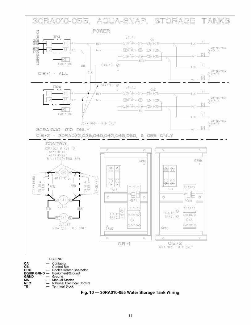
FIELD CONNECTIONSMain Power — Bring conduit and wire from the fused discon-nect switch through the hole in the base of the accessory tank.Connect the conduit to the control box through a knockout, andthe wires to terminals on the terminal block. To comply withNEC Article 440-14, the disconnect must be located withinsight from and readily accessible from the accessory tank. Re-fer to Fig. 10.Control Power — Control power is obtained from the chiller'smain power supply and does NOT require a separate source.The tank heaters are in an operative state when the EmergencyOn-Off switch on the chiller is in the OFF position.
11
LEGEND
Fig. 10 — 30RA010-055 Water Storage Tank Wiring
CA — ContactorCB — Control BoxCHC — Cooler Heater ContactorEQUIP GRND — Equipment/GroundGRND — GroundMS — Manual StarterNEC — National Electrical ControlTB — Terminal Block
Manufacturer reserves the right to discontinue, or change at any time, specifications or designs without notice and without incurring obligations.PC 903 Catalog No. 533-00025 Printed in U.S.A. Form 30RA-7SI Pg 12 1001 8-01 Replaces: NewBook 2
Tab 5c
Copyright 2001 Carrier Corporation
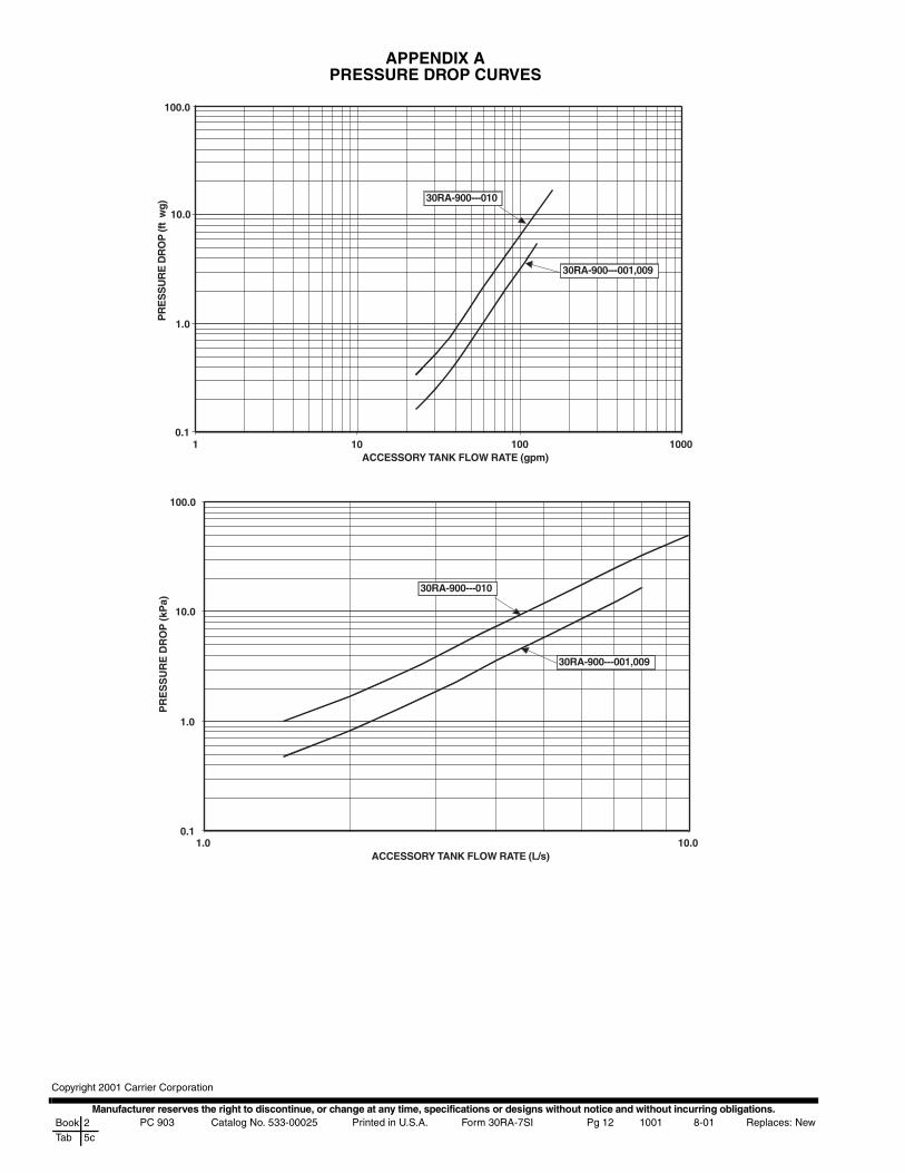
APPENDIX APRESSURE DROP CURVES
1ACCESSORY TANK FLOW RATE (gpm)
PR
ES
SU
RE
DR
OP
(ft
wg)
30RA-900---010
30RA-900---001,009
100.0
10.0
1.0
0.110 100 1000
0.1
1.0
10.0
1.0 10.0ACCESSORY TANK FLOW RATE (L/s)
PR
ES
SU
RE
DR
OP
(kP
a)
30RA-900---010
30RA-900---001,009
100.0