Embed Size (px)
Citation preview
November 16, 2005 05-73684/M-15400.ppt1October 29, 2008 08-75661/D08-328
Air, Thermal, and Water Air, Thermal, and Water Management for PEM Fuel Management for PEM Fuel
Cell SystemsCell SystemsHoneywell International
Torrance, CA
This research was supported, in whole or in part, by a DOE award, Cooperative Agreement No. DE-FC36-02AL67624 and DE-FC36-03GO13109 and that such support does not constitute an endorsement by DOE of the views expressed in the article.
2008 Fuel Cell Seminar & Exhibition2008 Fuel Cell Seminar & ExhibitionFuel Cells for a Greener World
October 29, 2008 08-75661/D08-3282
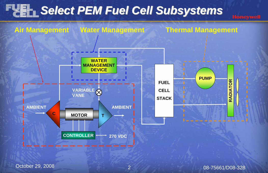
Select PEM Fuel Cell SubsystemsSelect PEM Fuel Cell SubsystemsSelect PEM Fuel Cell Subsystems
FUEL
CELL
STACK
Thermal Management
AMBIENT
CONTROLLER
VARIABLEVANE
MOTORC T
AMBIENT
270 VDC
PUMP
RA
DIA
TOR
Water ManagementAir Management
WATER MANAGEMENT
DEVICE
October 29, 2008 08-75661/D08-3283
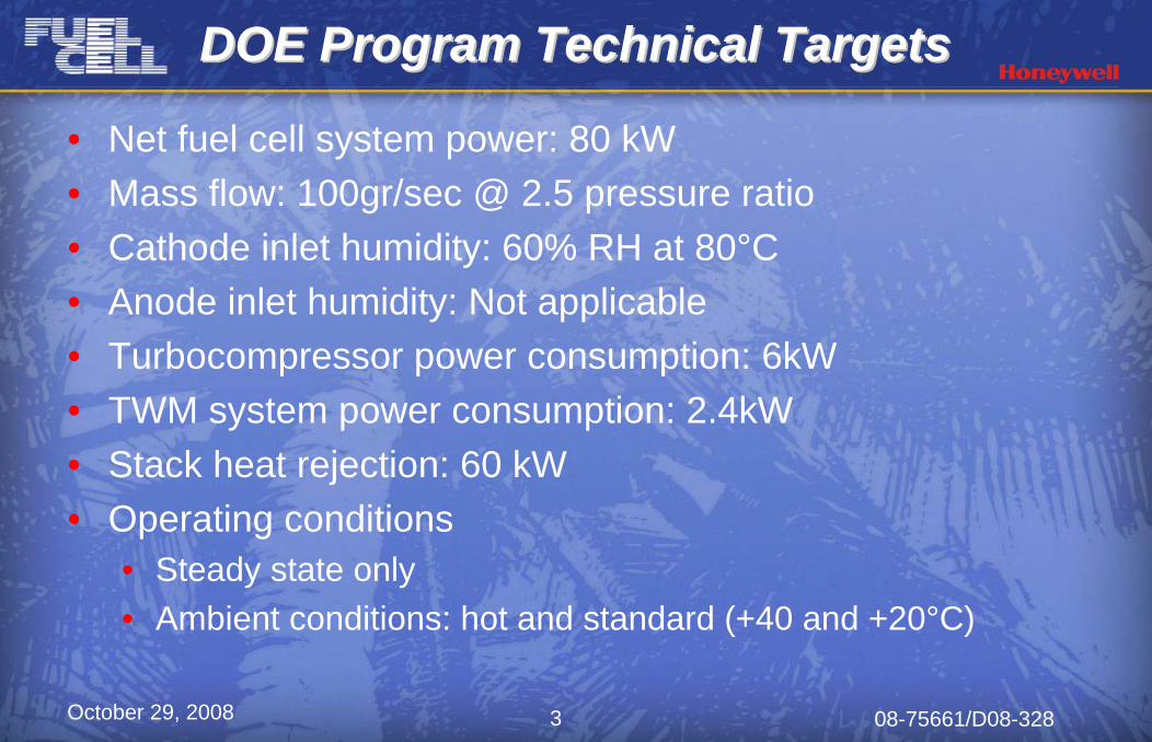
• Net fuel cell system power: 80 kW • Mass flow: 100gr/sec @ 2.5 pressure ratio• Cathode inlet humidity: 60% RH at 80°C• Anode inlet humidity: Not applicable• Turbocompressor power consumption: 6kW• TWM system power consumption: 2.4kW• Stack heat rejection: 60 kW• Operating conditions
• Steady state only• Ambient conditions: hot and standard (+40 and +20°C)
DOE Program Technical TargetsDOE Program Technical TargetsDOE Program Technical Targets
October 29, 2008 08-75661/D08-3284
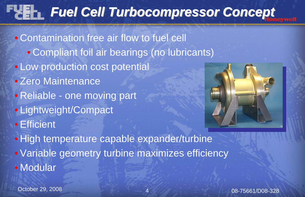
• Contamination free air flow to fuel cell• Compliant foil air bearings (no lubricants)
• Low production cost potential • Zero Maintenance• Reliable - one moving part• Lightweight/Compact• Efficient • High temperature capable expander/turbine• Variable geometry turbine maximizes efficiency• Modular
Fuel Cell Turbocompressor ConceptFuel Cell Turbocompressor ConceptFuel Cell Turbocompressor Concept
October 29, 2008 08-75661/D08-3285
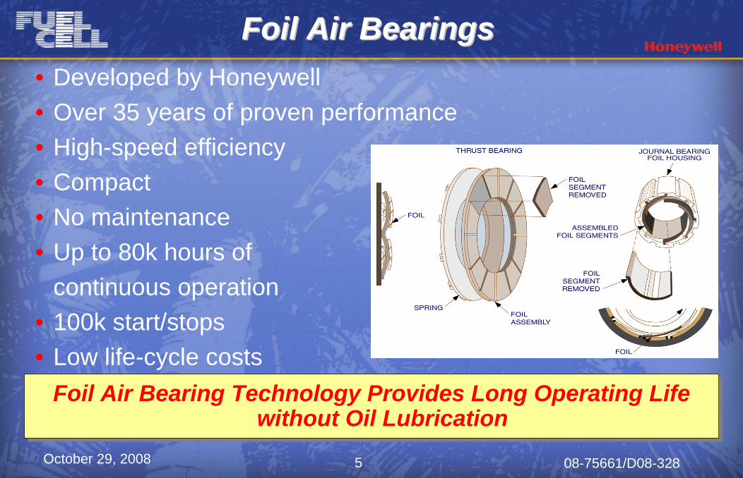
Foil Air Bearing Technology Provides Long Operating Life without Oil Lubrication
Foil Air Bearing Technology Provides Long Operating Life without Oil Lubrication
Foil Air BearingsFoil Air BearingsFoil Air Bearings• Developed by Honeywell• Over 35 years of proven performance• High-speed efficiency• Compact • No maintenance • Up to 80k hours of
continuous operation • 100k start/stops• Low life-cycle costs
October 29, 2008 08-75661/D08-3286
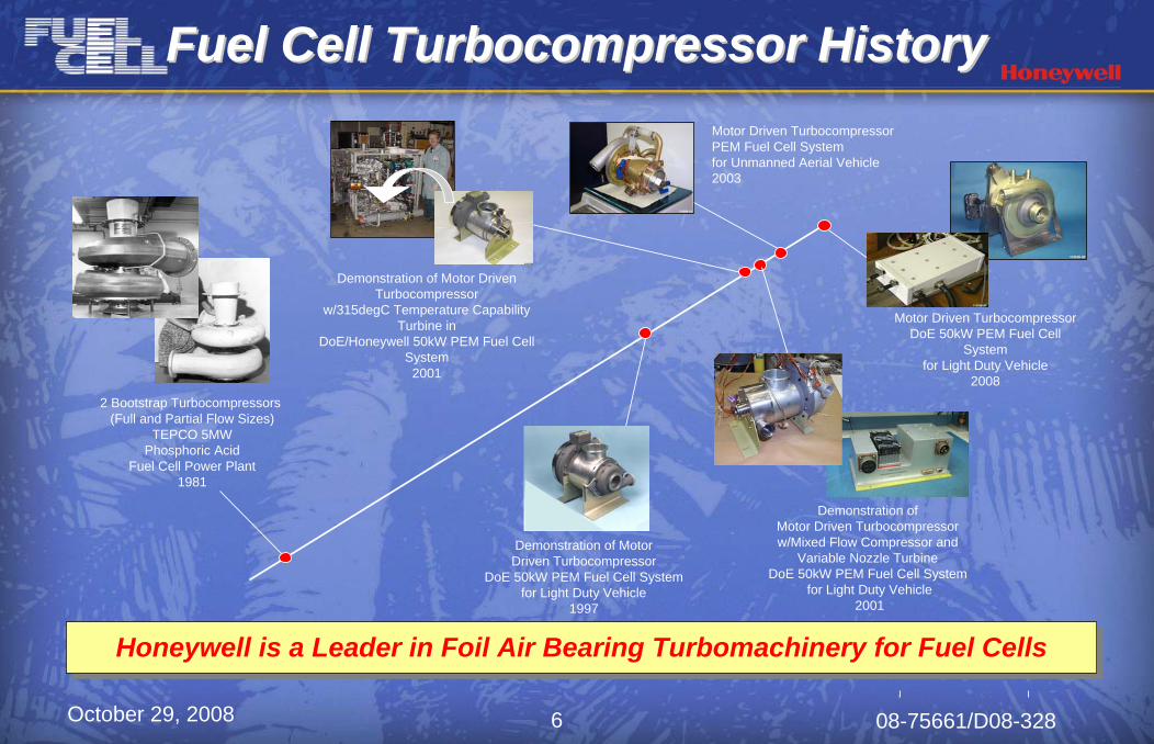
Fuel Cell Turbocompressor HistoryFuel Cell Turbocompressor HistoryFuel Cell Turbocompressor History
2 Bootstrap Turbocompressors (Full and Partial Flow Sizes)
TEPCO 5MWPhosphoric Acid
Fuel Cell Power Plant1981
Demonstration of Motor Driven Turbocompressor w/Mixed Flow Compressor and
Variable Nozzle Turbine DoE 50kW PEM Fuel Cell System
for Light Duty Vehicle2001
Demonstration of Motor Driven Turbocompressor
w/315degC Temperature Capability Turbine in
DoE/Honeywell 50kW PEM Fuel Cell System
2001
Motor Driven Turbocompressor DoE 50kW PEM Fuel Cell
System for Light Duty Vehicle
2008
Demonstration of MotorDriven Turbocompressor
DoE 50kW PEM Fuel Cell Systemfor Light Duty Vehicle
1997
Motor Driven Turbocompressor PEM Fuel Cell System for Unmanned Aerial Vehicle2003
Honeywell is a Leader in Foil Air Bearing Turbomachinery for Fuel CellsHoneywell is a Leader in Foil Air Bearing Turbomachinery for Fuel Cells
October 29, 2008 08-75661/D08-3287
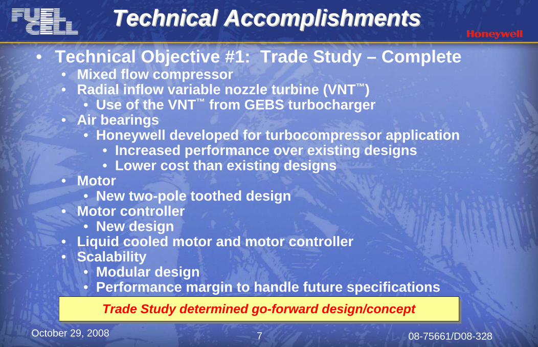
• Technical Objective #1: Trade Study – Complete• Mixed flow compressor• Radial inflow variable nozzle turbine (VNT™)
• Use of the VNT™ from GEBS turbocharger• Air bearings
• Honeywell developed for turbocompressor application• Increased performance over existing designs• Lower cost than existing designs
• Motor• New two-pole toothed design
• Motor controller• New design
• Liquid cooled motor and motor controller• Scalability
• Modular design• Performance margin to handle future specifications
Technical AccomplishmentsTechnical AccomplishmentsTechnical Accomplishments
Trade Study determined go-forward design/conceptTrade Study determined go-forward design/concept
October 29, 2008 08-75661/D08-3288
Technical AccomplishmentsTechnical AccomplishmentsTechnical Accomplishments
• Technical Objective #2: Turbocompressor• Design and analysis complete• Hardware fabricated and assembled• Demonstrators assembled
• Technical Objective #3: Motor and Motor Controller• Motor
• Design and analysis complete• Hardware fabricated and assembled• Demonstrators assembled
• Motor Controller• Design and analysis complete• Hardware fabricated and assembled• Demonstrators assembled
Design complete and hardware assembledDesign complete and hardware assembled
October 29, 2008 08-75661/D08-3289
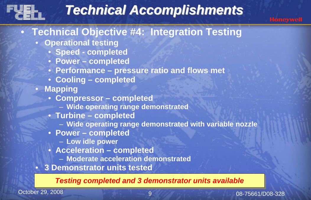
• Technical Objective #4: Integration Testing• Operational testing
• Speed - completed• Power – completed• Performance – pressure ratio and flows met• Cooling – completed
• Mapping• Compressor – completed
– Wide operating range demonstrated• Turbine – completed
– Wide operating range demonstrated with variable nozzle• Power – completed
– Low idle power• Acceleration – completed
– Moderate acceleration demonstrated• 3 Demonstrator units tested
Technical AccomplishmentsTechnical AccomplishmentsTechnical Accomplishments
Testing completed and 3 demonstrator units availableTesting completed and 3 demonstrator units available
October 29, 2008 08-75661/D08-32810
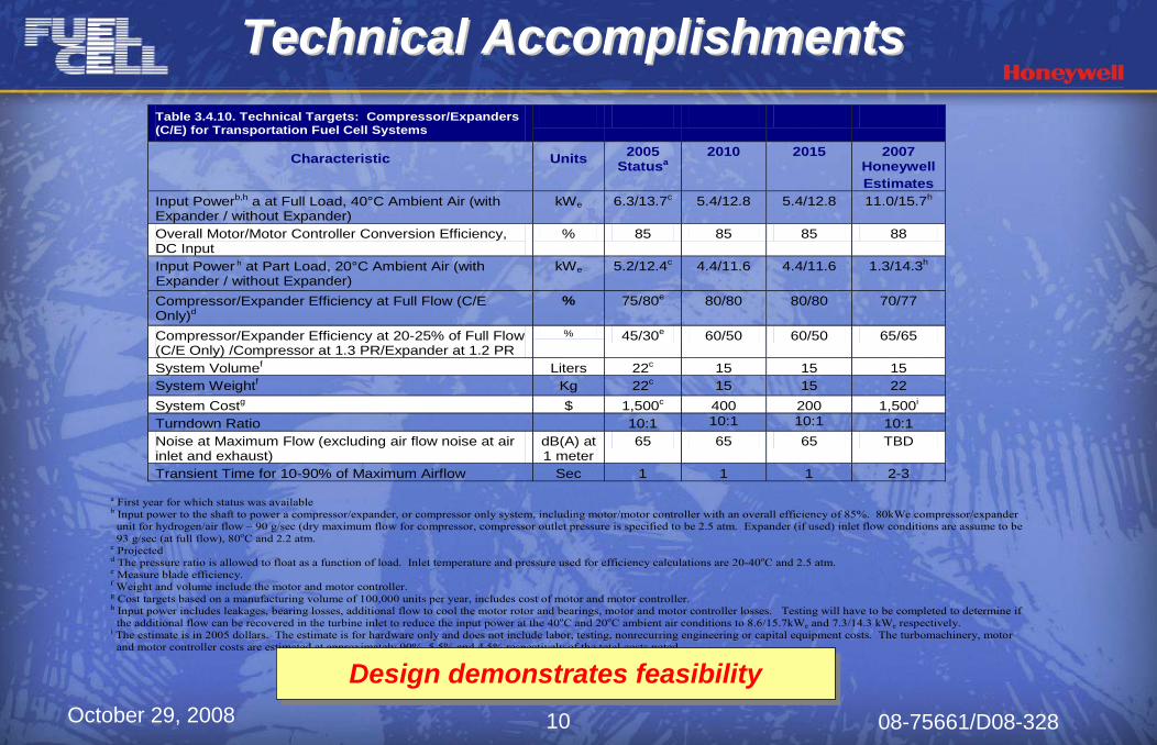
Table 3.4.10. Technical Targets: Compressor/Expanders (C/E) for Transportation Fuel Cell Systems
Characteristic Units 2005 Statusa
2010
2015 2007 Honeywell Estimates
Input Powerb,h a at Full Load, 40°C Ambient Air (with Expander / without Expander)
kWe 6.3/13.7c 5.4/12.8 5.4/12.8 11.0/15.7h
Overall Motor/Motor Controller Conversion Efficiency, DC Input
% 85 85 85 88
Input Power h at Part Load, 20°C Ambient Air (with Expander / without Expander)
kWe 5.2/12.4c 4.4/11.6 4.4/11.6 1.3/14.3h
Compressor/Expander Efficiency at Full Flow (C/E Only)d
% 75/80e 80/80 80/80 70/77
Compressor/Expander Efficiency at 20-25% of Full Flow (C/E Only) /Compressor at 1.3 PR/Expander at 1.2 PR
% 45/30e 60/50 60/50 65/65
System Volumef Liters 22c 15 15 15 System Weightf Kg 22c 15 15 22 System Costg $ 1,500c 400 200 1,500i
Turndown Ratio 10:1 10:1 10:1 10:1 Noise at Maximum Flow (excluding air flow noise at air inlet and exhaust)
dB(A) at 1 meter
65 65 65 TBD
Transient Time for 10-90% of Maximum Airflow Sec 1 1 1 2-3 a First year for which status was available b Input power to the shaft to power a compressor/expander, or compressor only system, including motor/motor controller with an overall efficiency of 85%. 80kWe compressor/expander unit for hydrogen/air flow – 90 g/sec (dry maximum flow for compressor, compressor outlet pressure is specified to be 2.5 atm. Expander (if used) inlet flow conditions are assume to be 93 g/sec (at full flow), 80oC and 2.2 atm.
c Projected d The pressure ratio is allowed to float as a function of load. Inlet temperature and pressure used for efficiency calculations are 20-40oC and 2.5 atm. e Measure blade efficiency. f Weight and volume include the motor and motor controller. g Cost targets based on a manufacturing volume of 100,000 units per year, includes cost of motor and motor controller. h Input power includes leakages, bearing losses, additional flow to cool the motor rotor and bearings, motor and motor controller losses. Testing will have to be completed to determine if the additional flow can be recovered in the turbine inlet to reduce the input power at the 40oC and 20oC ambient air conditions to 8.6/15.7kWe and 7.3/14.3 kWe respectively.
i The estimate is in 2005 dollars. The estimate is for hardware only and does not include labor, testing, nonrecurring engineering or capital equipment costs. The turbomachinery, motor and motor controller costs are estimated at approximately 90%, 5.5% and 4.5% respectively of the total costs noted.
Design demonstrates feasibilityDesign demonstrates feasibility
Technical AccomplishmentsTechnical AccomplishmentsTechnical Accomplishments
October 29, 2008 08-75661/D08-32811
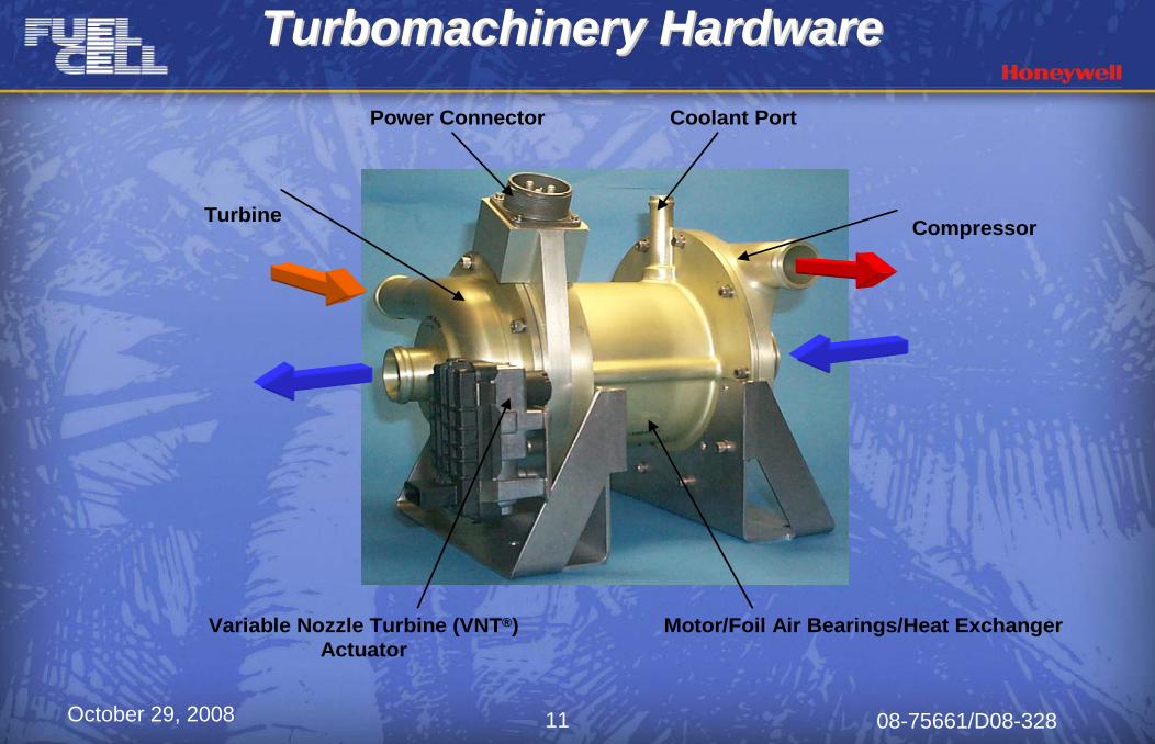
Turbomachinery HardwareTurbomachinery HardwareTurbomachinery Hardware
Compressor
Coolant Port
Variable Nozzle Turbine (VNT®)Actuator
Turbine
Motor/Foil Air Bearings/Heat Exchanger
Power Connector
October 29, 2008 08-75661/D08-32812
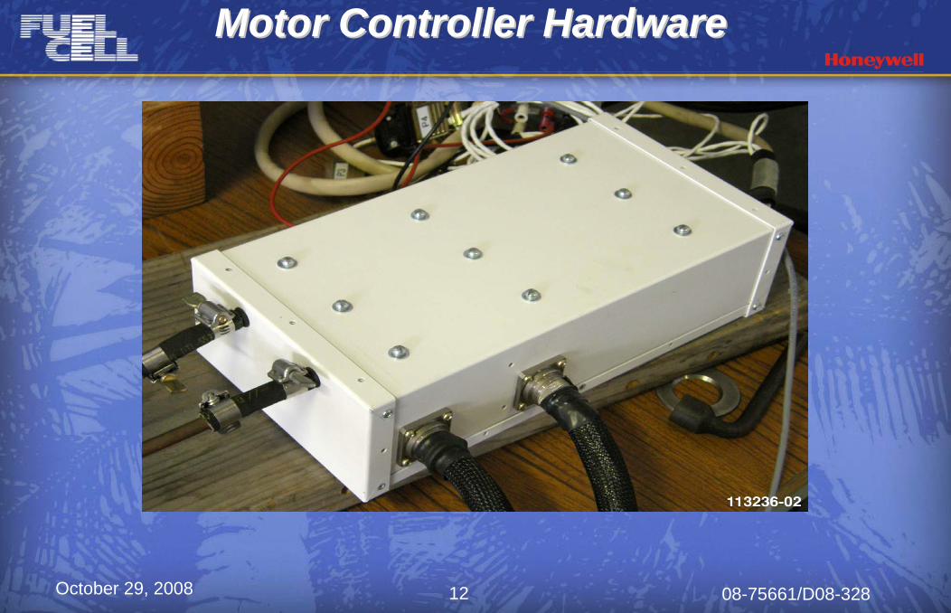
Motor Controller HardwareMotor Controller HardwareMotor Controller Hardware
October 29, 2008 08-75661/D08-32813
SummarySummarySummary
• Trade study completed• Analysis, design and fabrication completed• Testing completed
• Compressor, turbine, motor, motor controller and power mapping• Acceleration• Cooling
• Three (3) demonstrator units fabricated, assembled and tested• Units ready for delivery
• Areas to be further investigated• Power consumption• Weight• Cost
Program demonstrated wide operating range in a compact and flexible packageProgram demonstrated wide operating range in a compact and flexible package
October 29, 2008 08-75661/D08-32814
AMBIENT
CONTROLLER
VARIABLEVANE
AMBIENT
270 VDC
PUMPPUMP
RA
DIA
TOR
WATER MANAGEMENTNT DEVICE
MOTORR
C T
FUEL
CELL
STACK
MOTORR
C T
FUEL
CELL
STACK
FUEL
CELL
STACK
FUEL
CELL
STACK
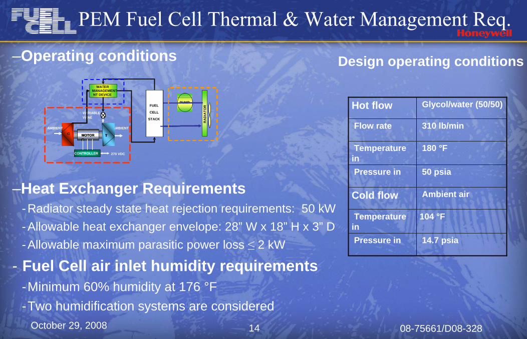
–Operating conditions
–Heat Exchanger Requirements-Radiator steady state heat rejection requirements: 50 kW-Allowable heat exchanger envelope: 28” W x 18” H x 3” D-Allowable maximum parasitic power loss ≤ 2 kW
- Fuel Cell air inlet humidity requirements-Minimum 60% humidity at 176 °F-Two humidification systems are considered
PEM Fuel Cell Thermal & Water Management Req.
Hot flow Glycol/water (50/50)
Flow rate 310 lb/min
Temperature in
180 °F
Pressure in 50 psia
Cold flow Ambient air
Temperature in
104 °F
Pressure in 14.7 psia
Design operating conditions
October 29, 2008 08-75661/D08-32815
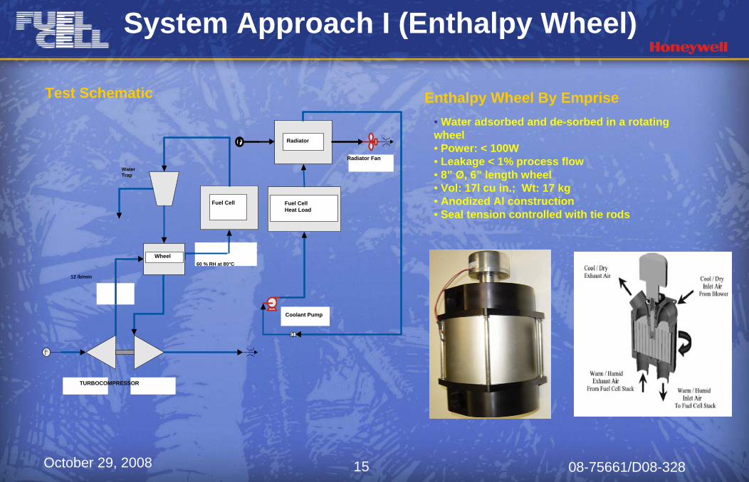
Enthalpy Wheel By Emprise• Water adsorbed and de-sorbed in a rotating wheel • Power: < 100W• Leakage < 1% process flow• 8” Ø, 6” length wheel• Vol: 17l cu in.; Wt: 17 kg• Anodized Al construction• Seal tension controlled with tie rods
Fuel Cell
Wheel
Fuel CellHeat Load
Radiator
Radiator Fan
Coolant Pump
12 lb/min
60 % RH at 80°C
Test Schematic
WaterTrap
TURBOCOMPRESSOR
System Approach I (Enthalpy Wheel)
October 29, 2008 08-75661/D08-32816
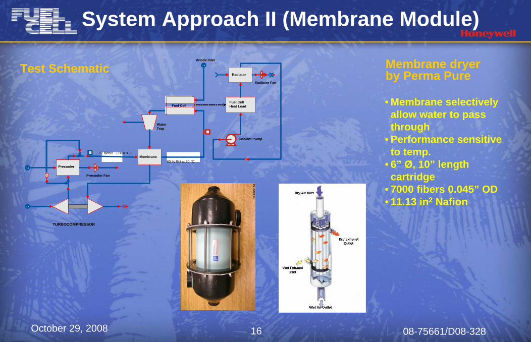
System Approach II (Membrane Module)
Precooler
Precooler Fan
Coolant Pump
Radiator
Radiator Fan
60 % RH at 80 °CMembrane
12 lb/min
Fuel Cell
Anode Inlet
Precooler
Fuel CellHeat Load
Radiator
60 % RH at 80 °CMembrane
Fuel Cell
WaterTrap
(<100 °C)
Test Schematic
TURBOCOMPRESSOR
Membrane dryer by Perma Pure
• Membrane selectively allow water to pass through
• Performance sensitive to temp.
• 6” Ø, 10” length cartridge
• 7000 fibers 0.045” OD• 11.13 in2 Nafion
October 29, 2008 08-75661/D08-32817
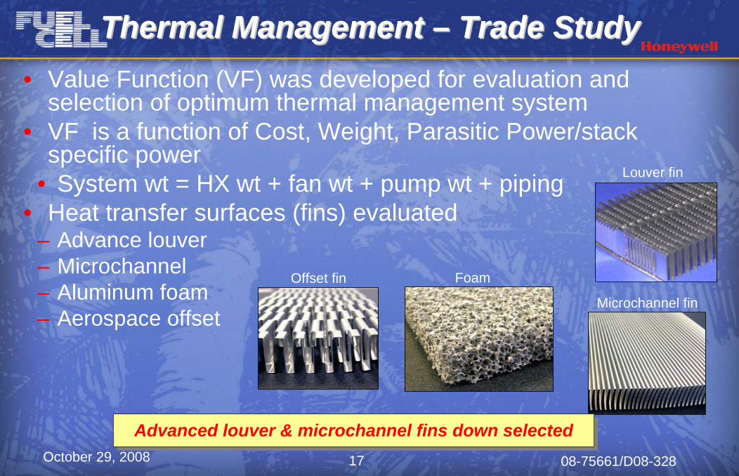
Thermal Management Thermal Management –– Trade StudyTrade Study• Value Function (VF) was developed for evaluation and
selection of optimum thermal management system• VF is a function of Cost, Weight, Parasitic Power/stack
specific power• System wt = HX wt + fan wt + pump wt + piping
• Heat transfer surfaces (fins) evaluated– Advance louver – Microchannel – Aluminum foam– Aerospace offset
Offset fin
Microchannel fin
Foam
Louver fin
Advanced louver & microchannel fins down selectedAdvanced louver & microchannel fins down selected
October 29, 2008 08-75661/D08-32818
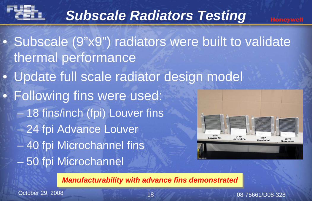
Subscale Radiators Testing
• Subscale (9”x9”) radiators were built to validate thermal performance
• Update full scale radiator design model• Following fins were used:
– 18 fins/inch (fpi) Louver fins– 24 fpi Advance Louver – 40 fpi Microchannel fins– 50 fpi Microchannel
Manufacturability with advance fins demonstratedManufacturability with advance fins demonstrated
October 29, 2008 08-75661/D08-32819
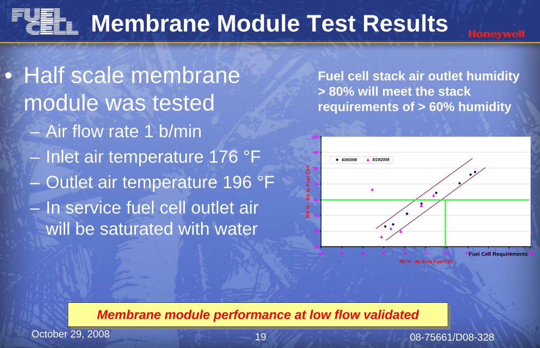
Membrane Module Test Results
• Half scale membrane module was tested – Air flow rate 1 b/min– Inlet air temperature 176 °F– Outlet air temperature 196 °F– In service fuel cell outlet air
will be saturated with water 30
40
50
60
70
80
90
100
50 55 60 65 70 75 80 85 90 95 100
RH % - Air from Fuel Cell
RH
% -
Air
to F
uel C
ell
8/29/2008 8/19/2008
Fuel Cell Requirements
Fuel cell stack air outlet humidity > 80% will meet the stack requirements of > 60% humidity
Membrane module performance at low flow validatedMembrane module performance at low flow validated
October 29, 2008 08-75661/D08-32820
Future WorkFuture Work
• Validate full scale humidification system performance – 2008/09
• Validate heat exchanger performance – 2008/09• Build & test two full scale radiators with two optimum
configurations – 2009• Demonstrate integrated fuel cell balance-of-plant
system performance– 2009/10
October 29, 2008 08-75661/D08-32821
Acknowledgments/PartnersAcknowledgments/Partners• U.S. Dept. of Energy (EERE)
• DE-FC36-02AL67624 • DE-FC36-03GO13109
• FreedomCAR Tech Team• Argonne National Laboratory (ANL)• Honeywell Transportation Systems• Emprise Corporation• Perma Pure LLC
This research was supported, in whole or in part, by a DOE award, Cooperative Agreement No. DE-FC04-02AL07624 and DE-FC36-03GO13109 and that such support does not constitute an endorsement by DOE of the views expressed in the article.
October 29, 2008 08-75661/D08-32822
ContactsContactsMukund Acharya
Fuel Cell Program ManagementPhoenix, AZ
Phone: (602) 231-2808E-mail: [email protected]
Mark GeeFuel Cell Air Management
Torrance, CAPhone: (310) 512-3606
E-mail: [email protected]
Zia MirzaFuel Cell Thermal & Water Management
Torrance, CAPhone: (310) 512-3374
E-mail: [email protected]