Embed Size (px)
Citation preview

TTER CONDITIONERS GREE MAKING BETTER CONDITIONERS GREE MAKING BETTER CONDITIONERS GREE MAKING BETTER CONDITIONER
TTER CONDITIONERS GREE MAKING BETTER CONDITIONERS GREE MAKING BETTER CONDITIONERS GREE MAKING BETTER CONDITIONER
TECHNICAL SALES GUIDE-50Hz
CAPACITY RANGE:6~16kW
SUPER HIGH AMBIENT OPERATION TO 48
(GC201308- )
GREE ELECTRIC APPLIANCES INC.OF ZHUHAI
AIR TO WATER HEAT PUMP VERSATI II SERIES

2
CONTENTSMODELS LIST ������������������������������������������������������������������������������������������������������������������������������������ 3
NOMENCLATURE ������������������������������������������������������������������������������������������������������������������������������ 4
BASIC SYSTEM CONFIGURATION ������������������������������������������������������������������������������������������������������ 5
FEATURES ����������������������������������������������������������������������������������������������������������������������������������������� 8
SPECIFICATION ��������������������������������������������������������������������������������������������������������������������������������� 9
PERFORMANCE CORRECTION ��������������������������������������������������������������������������������������������������������� 13
CAPACITY TABLES ���������������������������������������������������������������������������������������������������������������������������� 15
ELECTRICAL DATA ��������������������������������������������������������������������������������������������������������������������������� 16
FIELD WIRING DIAGRAM ����������������������������������������������������������������������������������������������������������������� 17
INSTALLATION �������������������������������������������������������������������������������������������������������������������������������� 19
ACCESSORIES ��������������������������������������������������������������������������������������������������������������������������������� 25

3
Versati II Series Air to Water Heat Pump Technical Sales Guide
1 MODELS LIST
1.1 Air to Water Heat Pump
1.2 Water Tank
Nominal Capacity Model Power Supply
Btu/h Refrigerant Model Name V,Ph,Hz
20400
R410A
GRS-CQ6.0Pd/NaB-K
220-240V,~,50Hz
27300 GRS-CQ8.0Pd/NaB-K
34100 GRS-CQ10Pd/NaB-K
40900 GRS-CQ12Pd/NaB-K
47800 GRS-CQ14Pd/NaB-K
54600 GRS-CQ16Pd/NaB-K
40900 GRS-CQ12Pd/NaB-M
380-415V,3N~,50Hz 47800 GRS-CQ14Pd/NaB-M
54600 GRS-CQ16Pd/NaB-M
Model Litre Remarks
Model Name L Inner coil
SXVD200LCJ/A-K 200
Only an inner coil connected to master unit ;
SXVD200LCJ2/A-K An inner coil connected to master unit; another connected to other heat source ;
SXVD300LCJ/A-K 300
Only an inner coil connected to master unit ;
SXVD300LCJ2/A-K An inner coil connected to master unit; another connected to other heat source ;
SXVD200LCJ/A-M200
Only an inner coil connected to master unit ;
SXVD200LCJ2/A-M An inner coil connected to master unit; another connected to other heat source ;
SXVD300LCJ/A-M300
Only an inner coil connected to master unit;
SXVD300LCJ2/A-M An inner coil connected to master unit; another connected to other heat source ;
SXVD200LCJ/A-H200
Only an inner coil connected to master unit;
SXVD200LCJ2/A-H An inner coil connected to master unit; another connected to other heat source ;
SXVD300LCJ/A-H300
Only an inner coil connected to master unit;
SXVD300LCJ2/A-H An inner coil connected to master unit; another connected to other heat source ;

4
SX V D 300 L C J2 / A - K
1 2 3 4 5 6 7 8 9
NO. Description Options
1 Symbol of Heat Pump Water Tank SX
2 Tank TypeOmit-Common heat pump water tank; V-Heat pump water tank for multi VRF system
3 Function Code Omit-No electric heating function; D-Electric heating function available
4 Nominal Water Tank Volume 300=300L
5 Structure Type B-Wall mounted type; L-Floor standing type
6 Bearing Omit-Non-bearing water tank; C-Bearing water tank
7 Type of Heat Exchange TubeOmit-No heat exchanger; J-Inner coil static heating(J-Single coil; J2-Double coils); JW-Outer coil static heating
8 Serial Number A,B,C……
9 Power Supply K=220-240V,~,50Hz; M=380-415V,3N~,50Hz; H=380V,3N~,60Hz
2.1 Nomenclature of the Main Unit
2.2 Nomenclature of the Water Tank
2 NOMENCLATURE
G RS - C Q 16 Pd / Na B - K (O)
1 2 3 4 5 6 7 8 9 10
NO. Description Options
1 GREE G
2 Heat Pump Water Heater RS
3 Heating Mode S= Static; C=Circulating
4 Function Q=Multi-function; Omit=Single-function
5 Nominal Heating Capacity 6=6.0kW; 8=8.0kW;10=10kW; 12=12kW; 14=14kW; 16=16kW
6 Compressor Style Pd=DC Inverter; Omit=On/Off
7 Refrigerant Na=R410A
8 Design Serial Number B,C,D......
9 Power Supply K=220-240V,~,50Hz; M=380-415V,3N~,50Hz; H=380V,3N~,60Hz
10 Indoor and Outdoor Unit Code I=Indoor unit; O=Outdoor unit

5
Versati II Series Air to Water Heat Pump Technical Sales Guide
33.1 System Connection Diagram
3.2 Installation Demonstration
BASIC SYSTEM CONFIGURATION
CASE 1: Connecting Under-floor coil for heating and cooling
Note
1.Type of thermostat and specification should be complied with installation of this manual;2.By pass valve must be installed to secure enough water flow rate,and by pass valve should be installed at the collector.
Outdoor unitIndoor unit
Fan coil system
Floor heating system
Coil water tank
Tap water
Washer tray
Shower
B
Under-floor coil
Outdoor Indoor
T
Shut off value By-pass value(Field supply)Remote room Thermostat(Field supply)
High temperature line Low temperature line
T B
6
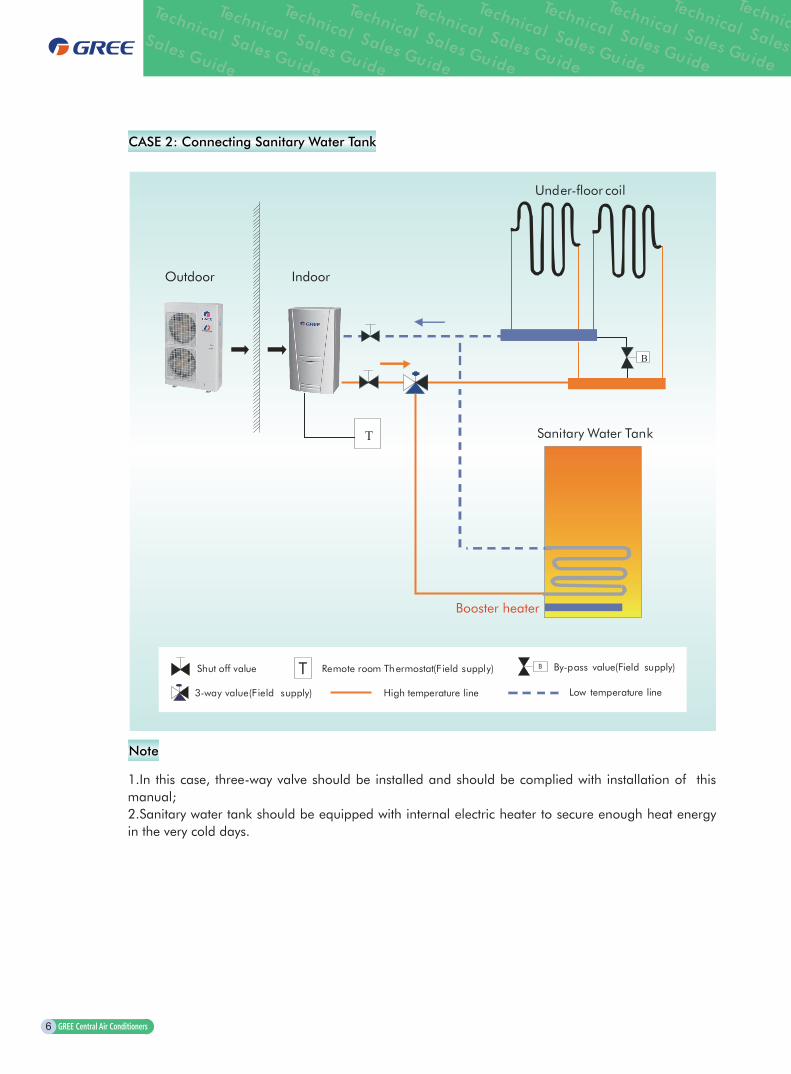
CASE 2: Connecting Sanitary Water Tank
1.In this case, three-way valve should be installed and should be complied with installation of this manual;2.Sanitary water tank should be equipped with internal electric heater to secure enough heat energy in the very cold days.
Note
Shut off value By-pass value(Field supply)Remote room Thermostat(Field supply)
High temperature line Low temperature line
T B
3-way value(Field supply)
B
Under-floor coil
Sanitary Water TankT
IndoorOutdoor

7
Versati II Series Air to Water Heat Pump Technical Sales Guide
CASE 3: Connecting Sanitary Water Tank and Heat Emitters for heating and Cooling
Two-way valve is very important to prevent dew condensation on the floor and Radiator while cooling mode.
Note
Shut off value By-pass value(Field supply)Remote room Thermostat(Field supply)
High temperature temperature line line
T B
3-way value (Field supply)
B
Outdoor Indoor
Sanitary Water Tank
FCU 1 FCU2
M
Radiator
T
Under-floor coil
M2-way value(Field supply)

8
4 FEATURES
4.1 Outdoor Unit
4.2 Indoor Unit
4.3 Sanitary Water Tank
Inverter Control;BLDC Fan Motor Control;DC Inverter Compressor; Soft Operation by Sine Wave;PFC Step-up Technology;High Efficiency Fan & Grille High Volume Axial Fan Makes Powerful Cooling and Maintains System Stable;Deluxe Controller and Smart Control Emergency Operation Mode; Central Control; Weekly Programmable;Quick Water Heating Mode;Disinfection Operation; Holiday Mode; Silent Mode; Forced Operation Mode;Weather-Dependent Operation; Energy-saving and High Efficiency;New Refrigerant and Friendly to Earth;Floor Commissioning;Air removal of the water system.
Compact Sizes : 900×500×324mm(W×D×H);Deluxe Design;High COP Plate Heat Exchanger;High Efficient Pump;
Installation in Water Heating System; Rapid Storage and Continuous Delivery;High Efficiency for Low Running Costs;CFC Free Insulation; Stainless Steel Tank and Coil;Magnesium Anode;Complete, Easy to Use and Maintain;Double Coil and Double Temperature Sensor Design;

9
Versati II Series Air to Water Heat Pump Technical Sales Guide
5 SPECIFICATION
5.1 Outdoor Unit
Due to continues improvement on the products, the specifications listed above are subject to change without notice, and the ones on the products nameplate should be referred to as final.
Mod
elGR
S-CQ
6.0P
d/Na
B-K(
O)
GRS-
CQ8.
0Pd/
NaB-
K(O
)GR
S-CQ
10Pd
/NaB
-K(O
)GR
S-CQ
12Pd
/NaB
-K(O
)GR
S-CQ
14Pd
/NaB
-K(O
)
Cap
acity
*1
Coo
ling
(floo
r co
olin
g)kW
5.7
9.5
1112
.513
.5
Hea
ting
(floo
r he
atin
g)kW
6.5
910
12.5
13.5
Pow
er
Inpu
t*1
Coo
ling
(floo
r co
olin
g)kW
1.63
2.57
3.24
3.57
4.09
Hea
ting
(floo
r he
atin
g)
kW1.
572.
172.
442.
813.
07
EER/
CO
P*1
W/W
3.5/
4.15
3.7/
4.15
3.4/
4.1
3.5/
4.45
3.3/
4.4
Cap
acity
*2
Coo
ling
(for
Fan
coil)
kW
57
8.5
9.5
10
Hea
ting
(Fan
coi
l or
Radi
ator
) kW
5.8
8.5
911
12
Pow
er
Inpu
t*2
Coo
ling
(for
Fan
coil)
kW
1.85
2.59
3.15
3.39
3.57
Hea
ting
(Fan
coi
l or
Radi
ator
) kW
1.9
2.79
2.81
3.14
3.48
EER/
CO
P*2
W/W
2.7/
3.05
2.7/
3.05
2.7/
3.2
2.8/
3.5
2.8/
3.45
Refr
iger
ant c
harg
e vo
lum
ekg
1.7
2.1
2.1
3.2
3.2
Sani
tary
wat
er T
empe
ratu
re40
~80
40~
8040
~80
40~
8040
~80
Soun
d Pr
essu
re
Leve
l
cool
ing
dB(A
)57
5757
5555
heat
ing
dB(A
)59
5959
5757
Con
nect
ing
pipe
Gas
inch
(mm
)φ
1/2(
12.7
)φ
5/8(
15.9
)φ
5/8(
15.9
)φ
5/8(
15.9
)φ
5/8(
15.9
)
Liqu
idin
ch(m
m)
φ1/
4(6.
35)
φ3/
8(9.
52)
φ3/
8(9.
52)
φ3/
8(9.
52)
φ3/
8(9.
52)
Dim
ensi
ons
(W×
D×
H)
Out
line
mm
921×
427×
791
921×
427×
791
921×
427×
791
900×
412×
1345
900×
412×
1345
Pack
aged
mm
1065
×48
5×84
010
65×
485×
840
1065
×48
5×84
099
8×45
8×15
1599
8×45
8×15
15
Net
wei
ght/
Gro
ss w
eigh
tkg
66/7
166
/71
66/7
110
6/11
810
6/11
8
Load
ing
quan
tity
40'G
P-
9696
9652
52
40'H
Q-
144
144
144
5252

10
1Capacities and power inputs are based on the following conditions: Cooling conditions: Indoor Water Temperature 23 /18 ; Outdoor Air Temperature 35 DB/24 WB; Heating conditions:Indoor Water Temperature 30 /35 ; Outdoor Air Temperature 7 DB/6 WB; Standard piping length 7.5m
2 Capacities and power inputs are based on the following conditions; Cooling conditions:Indoor Water Temperature 12 /7 ; Outdoor Air Temperature 35 DB/24 WB; Heating conditions:Indoor Water Temperature 40 /45 ; Outdoor Air Temperature 7 DB/6 WB; Standard piping length 7.5m
Note
Mod
elG
RS-C
Q16
Pd/N
aB-K
(O)
GRS
-CQ
12Pd
/NaB
-M(O
)G
RS-C
Q14
Pd/N
aB-M
(O)
GRS
-CQ
16Pd
/NaB
-M(O
)
Cap
acity
*1
Coo
ling
(floo
r co
olin
g)kW
14.5
1415
.515
Hea
ting
(floo
r he
atin
g)kW
15.5
1314
16
Pow
erIn
put*
1
Coo
ling
(floo
r co
olin
g)kW
4.53
4.12
4.63
4.62
Hea
ting
(floo
r he
atin
g)
kW3.
782.
863.
183.
9
EER/
CO
P*1
W/W
3.2/
4.1
3.4/
4.55
3.35
/4.4
3.25
/4.1
Cap
acity
*2
Coo
ling
(for
Fan
coil)
kW
10.5
10.5
1111
.5
Hea
ting
(Fan
coi
l or
Radi
ator
) kW
1411
.512
14.5
Pow
er
Inpu
t*2
Coo
ling
(for
Fan
coil)
kW
3.96
3.56
3.93
4.26
Hea
ting
(Fan
coi
l or
Radi
ator
) kW
42.
953.
384.
03
EER/
CO
P*2
W/W
2.65
/3.5
2.95
/3.9
2.8/
3.55
2.7/
3.6
Refr
iger
ant c
harg
e vo
lum
ekg
3.2
3.4
3.4
3.4
Sani
tary
wat
er T
empe
ratu
re40
~80
40~
8040
~80
40~
80
Soun
d Pr
essu
re
Leve
l
cool
ing
dB(A
)57
5555
57
heat
ing
dB(A
)58
5757
58
Con
nect
ing
pipe
Gas
inch
(mm
)φ
5/8(
15.9
)φ
5/8(
15.9
)φ
5/8(
15.9
)φ
5/8(
15.9
)
Liqu
idin
ch(m
m)
φ3/
8(9.
52)
φ3/
8(9.
52)
φ3/
8(9.
52)
φ3/
8(9.
52)
Dim
ensi
ons
(W×
D×
H)
Out
line
mm
900×
412×
1345
900×
412×
1345
900×
412×
1345
900×
412×
1345
Pack
aged
mm
998×
458×
1515
998×
458×
1515
998×
458×
1515
998×
458×
1515
Net
wei
ght/
Gro
ss w
eigh
tkg
106/
118
108/
120
108/
120
108/
120
Load
ing
quan
tity
40'G
P-
5252
5252
40'H
Q-
5252
5252

11
Versati II Series Air to Water Heat Pump Technical Sales Guide
5.2 Indoor Unit
Mod
el
GRS
-CQ
6.0P
d/N
aB-K
(I)G
RS-C
Q8.
0Pd/
NaB
-KI)
GRS
-CQ
10Pd
/NaB
-K(I)
GRS
-CQ
12Pd
/NaB
-K(I)
GRS
-CQ
14Pd
/NaB
-KI)
Pow
er S
uppl
yV/
Ph/H
z1/
220-
240/
501/
220-
240/
501/
220-
240/
501/
220-
240/
501/
220-
240/
50
Nor
min
al in
put
W32
0062
0062
0062
0062
00
Leav
ing
wat
er
tem
pera
ture
Coo
ling*
17~
257~
257~
257~
257~
25
Coo
ling*
218
~25
18~
2518
~25
18~
2518
~25
Hea
ting*
125
~55
(Hig
h te
mpe
ratu
re c
ycle
)
Hea
ting*
225
~45
(Low
tem
pera
ture
cyc
le )
Pum
p
Type
-
Wat
er-c
oole
dW
ater
-coo
led
Wat
er-c
oole
dW
ater
-coo
led
Wat
er-c
oole
d
Nr.
of s
peed
-3
33
33
Pow
er in
put
W20
020
020
020
020
0
Wat
er fl
ow
limit
LPM
7.5
7.5
7.5
7.5
7.5
Elec
tric
H
eate
r
Ope
ratio
n-
Aut
omat
icA
utom
atic
Aut
omat
icA
utom
atic
Aut
omat
ic
Step
s-
22
22
2
Cap
acity
kW3
33
33
Com
bina
tion
kW1.
5+1.
53+
33+
33+
33+
3
Pow
er in
put
Ph/V
/Hz
1/23
0/50
1/23
0/50
1/23
0/50
1/23
0/50
1/23
0/50
Soun
d pr
essu
re le
vel
dB(A
)31
3131
3131
Con
nect
ing
pipe
Gas
inch
(mm
)φ
1/2(
12.7
)φ
5/8(
15.9
)φ
5/8(
15.9
)φ
5/8(
15.9
)φ
5/8(
15.9
)
Liqu
idin
ch(m
m)
φ1/
4(6.
35)
φ3/
8(9.
52)
φ3/
8(9.
52)
φ3/
8(9.
52)
φ3/
8(9.
52)
Dim
ensi
ons
(W×
D×
H)
Out
line
mm
900x
500x
324
900x
500x
324
900x
500x
324
900x
500x
324
900x
500x
324
Pack
aged
mm
1040
×60
5×38
010
40×
605×
380
1040
×60
5×38
010
40×
605×
380
1040
×60
5×38
0
Net
wei
ght/
Gro
ss w
eigh
tkg
52/6
252
/62
52/6
257
/66
57/6
6
Load
ing
quan
tity
40'G
P/40
'HQ
-20
5/24
620
5/24
620
5/24
620
5/24
620
5/24
6

12
Mod
el
GRS
-CQ
16Pd
/NaB
-K(I)
GRS
-CQ
12Pd
/NaB
-M(I)
GRS
-CQ
14Pd
/NaB
-M(I)
GRS
-CQ
16Pd
/NaB
-M(I)
Pow
er S
uppl
yV/
Ph/H
z1/
220-
240/
503/
380-
415/
503/
380-
415/
503/
380-
415/
50
Nor
min
al in
put
W62
0062
0062
0062
00
Leav
ing
wat
er
tem
pera
ture
Coo
ling*
17~
257~
257~
257~
25
Coo
ling*
218
~25
18~
2518
~25
18~
25
Hea
ting*
125
~55
(Hig
h te
mpe
ratu
re c
ycle
)
Hea
ting*
225
~45
(Low
tem
pera
ture
cyc
le )
Pum
p
Type
-
Wat
er-c
oole
dW
ater
-coo
led
Wat
er-c
oole
dW
ater
-coo
led
Nr.
of s
peed
-3
33
3
Pow
er in
put
W20
020
020
020
0
Wat
er fl
ow
limit
LPM
7.5
7.5
7.5
7.5
Elec
tric
H
eate
r
Ope
ratio
n-
Aut
omat
icA
utom
atic
Aut
omat
icA
utom
atic
Step
s-
21
11
Cap
acity
kW3
66
6
Com
bina
tion
kW3+
36
66
Pow
er in
put
Ph/V
/Hz
1/23
0/50
3/40
0/50
3/40
0/50
3/40
0/50
Soun
d pr
essu
re le
vel
dB(A
)31
3131
31
Con
nect
ing
pipe
Gas
inch
(mm
)φ
5/8(
15.9
)φ
5/8(
15.9
)φ
5/8(
15.9
)φ
5/8(
15.9
)
Liqu
idin
ch(m
m)
φ3/
8(9.
52)
φ3/
8(9.
52)
φ3/
8(9.
52)
φ3/
8(9.
52)
Dim
ensi
ons
(W×
D×
H)
Out
line
mm
900x
500x
324
900x
500x
324
900x
500x
324
900x
500x
324
Pack
aged
mm
1040
×60
5×38
010
40×
605×
380
1040
×60
5×38
010
40×
605×
380
Net
wei
ght/
Gro
ss w
eigh
tkg
57/6
657
/66
57/6
657
/66
Load
ing
quan
tity
40'G
P/40
'HQ
-20
5/24
620
5/24
620
5/24
620
5/24
6
1 For FCU2 For Floor
Note

13
Versati II Series Air to Water Heat Pump Technical Sales Guide
5.3 Water Tank
6.1 Correction of Temperature
ModelSXVD200LCJ/A-KSXVD200LCJ/A-MSXVD200LCJ/A-H
SXVD200LCJ2/A-KSXVD200LCJ2/A-MSXVD200LCJ2/A-H
SXVD300LCJ/A-KSXVD300LCJ/A-MSXVD300LCJ/A-H
SXVD300LCJ2/A-KSXVD300LCJ2/A-MSXVD300LCJ2/A-H
Water Tank Volume L 200 300
Electric Heater Power W 3000
Connection Pipe
Cool Water Inlet
inch 1/2‘’ Female BSP
Hot Water Outlet
inch 1/2‘’ Female BSP
Circulation Water Inlet
inch 3/4‘’ Female BSP
Circulation Water Outlet
inch 3/4‘’ Female BSP
Outline Dimension ( D×H) mm 540×1595 620×1620
Net Weight kg 68 71 82 87
6 PERFORMANCE CORRECTION
Cooling Capacity Correction
GRS-CQ6.0Pd/NaB-K,GRS-CQ8.0Pd/NaB-K, GRS-CQ10Pd/NaB-K, GRS-CQ12Pd/NaB-K, GRS-CQ14Pd/NaB-K,GRS-CQ16Pd/NaB-K,GRS-CQ12Pd/NaB-M, GRS-CQ14Pd/NaB-M,GRS-CQ16Pd/NaB-M:
Performance correction
Leaving Chilled Water ( )Ambient Temperature ( )
25(77) 30(86) 35(95) 40(104) 45(113)
5(41.0) 0.995 0.955 0.905 0.855 0.805
6(42.8) 1.045 1.005 0.955 0.905 0.855
7(44.6) 1.090 1.050 1.000 0.950 0.900
8(46.4) 1.145 1.102 1.052 1.000 0.950
9(48.2) 1.190 1.150 1.100 1.050 1.002
10(50.0) 1.245 1.200 1.150 1.100 1.050
11(51.8) 1.290 1.250 1.202 1.152 1.102
12(53.6) 1.340 1.300 1.252 1.200 1.152
13(55.4) 1.390 1.350 1.302 1.252 1.202
14(57.2) 1.442 1.402 1.350 1.302 1.252
15(59.0) 1.490 1.450 1.400 1.350 1.302
18(64.4) 1.539 1.502 1.451 1.402 1.350
Computer of actual cooling capacity:Actual cooling capacity = nominal cooling capacity x cooling capacity correction coefficient.
14
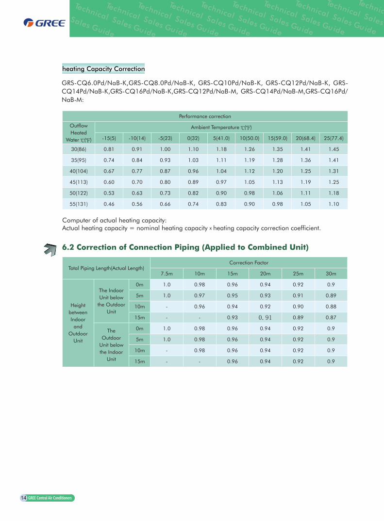
heating Capacity Correction
Computer of actual heating capacity:Actual heating capacity = nominal heating capacity x heating capacity correction coefficient.
Performance correction
Outflow Heated
Water ( )
Ambient Temperature ( )
-15(5) -10(14) -5(23) 0(32) 5(41.0) 10(50.0) 15(59.0) 20(68.4) 25(77.4)
30(86) 0.81 0.91 1.00 1.10 1.18 1.26 1.35 1.41 1.45
35(95) 0.74 0.84 0.93 1.03 1.11 1.19 1.28 1.36 1.41
40(104) 0.67 0.77 0.87 0.96 1.04 1.12 1.20 1.25 1.31
45(113) 0.60 0.70 0.80 0.89 0.97 1.05 1.13 1.19 1.25
50(122) 0.53 0.63 0.73 0.82 0.90 0.98 1.06 1.11 1.18
55(131) 0.46 0.56 0.66 0.74 0.83 0.90 0.98 1.05 1.10
6.2 Correction of Connection Piping (Applied to Combined Unit)
Total Piping Length(Actual Length)Correction Factor
7.5m 10m 15m 20m 25m 30m
Height between Indoor and
Outdoor Unit
The Indoor Unit below
the Outdoor Unit
0m 1.0 0.98 0.96 0.94 0.92 0.9
5m 1.0 0.97 0.95 0.93 0.91 0.89
10m - 0.96 0.94 0.92 0.90 0.88
15m - - 0.93 0.91 0.89 0.87
The Outdoor
Unit below the Indoor
Unit
0m 1.0 0.98 0.96 0.94 0.92 0.9
5m 1.0 0.98 0.96 0.94 0.92 0.9
10m - 0.98 0.96 0.94 0.92 0.9
15m - - 0.96 0.94 0.92 0.9
GRS-CQ6.0Pd/NaB-K,GRS-CQ8.0Pd/NaB-K, GRS-CQ10Pd/NaB-K, GRS-CQ12Pd/NaB-K, GRS-CQ14Pd/NaB-K,GRS-CQ16Pd/NaB-K,GRS-CQ12Pd/NaB-M, GRS-CQ14Pd/NaB-M,GRS-CQ16Pd/NaB-M:

15
Versati II Series Air to Water Heat Pump Technical Sales Guide
Model DB/WB(oC)
Floor heating water outlet temp 35oC Fan coil water outlet temp 45oC Radiator water outlet 55oC
Heating capacity
(kW)
Power input (kW)
COPHeating capacity
(kW)
Power input (kW)
COPHeating capacity
(kW)
Power input (kW)
COP
GRS-CQ6.0Pd/NaB-K
7/6 6.50 1.56 4.15 5.80 1.90 3.05 4.55 1.94 2.35
2/1 4.90 1.49 3.30 3.99 1.54 2.60 3.63 1.90 1.91
-7/-8 3.57 1.32 2.71 3.14 1.47 2.14 2.92 1.77 1.65
-15/-16 2.64 1.24 2.12 2.39 1.38 1.74 2.09 1.67 1.25
GRS-CQ8.0Pd/NaB-K
7/6 9.00 2.17 4.15 8.50 2.78 3.05 6.67 2.89 2.31
2/1 6.63 2.01 3.30 5.88 2.24 2.62 5.32 2.82 1.88
-7/-8 4.82 1.74 2.76 4.61 2.19 2.10 4.29 2.63 1.63
-15/-16 3.56 1.66 2.14 3.51 2.11 1.67 3.10 2.52 1.23
GRS-CQ10Pd/NaB-K
7/6 10.00 2.44 4.10 9.00 2.80 3.20 7.23 3.12 2.32
2/1 7.66 2.36 3.25 6.32 2.40 2.63 5.65 2.99 1.89
-7/-8 5.85 2.09 2.80 5.21 2.76 1.89 4.67 2.82 1.65
-15/-16 4.33 1.99 2.18 4.19 2.65 1.58 3.36 2.67 1.26
GRS-CQ12Pd/NaB-K
7/6 12.50 2.80 4.45 11.00 3.14 3.50 10.20 3.90 2.60
2/1 8.48 2.62 3.24 7.81 2.98 2.62 7.78 3.67 2.12
-7/-8 6.87 2.60 2.64 6.05 2.76 2.19 6.01 3.53 1.70
-15/-16 5.34 2.58 2.07 4.90 2.85 1.72 4.31 3.33 1.29
GRS-CQ14Pd/NaB-K
7/6 13.50 3.07 4.40 12.00 3.48 3.45 11.50 4.42 2.60
2/1 9.04 2.72 3.32 8.26 3.09 2.67 8.12 3.77 2.15
-7/-8 7.55 2.67 2.83 6.61 2.86 2.31 6.24 3.52 1.77
-15/-16 5.68 2.54 2.23 5.12 2.86 1.79 4.57 3.32 1.38
GRS-CQ16Pd/NaB-K
7/6 15.50 3.78 4.10 14.00 4.00 3.50 12.95 4.88 2.65
2/1 9.30 2.97 3.13 8.59 3.29 2.61 9.05 4.53 2.00
-7/-8 8.57 3.39 2.53 8.04 3.53 2.28 7.29 4.37 1.67
-15/-16 6.35 3.23 1.97 5.96 3.42 1.74 5.27 3.82 1.38
GRS-CQ12Pd/NaB-M
7/6 13.00 2.85 4.55 11.50 2.95 3.90 11.00 3.55 3.10
2/1 8.66 2.70 3.21 8.03 3.06 2.62 8.21 4.02 2.04
-7/-8 6.84 2.65 2.58 6.25 3.19 1.96 6.45 3.88 1.66
-15/-16 5.36 2.59 2.07 4.92 3.15 1.56 4.63 3.82 1.21
GRS-CQ14Pd/NaB-M
7/6 14.00 3.18 4.40 12.00 3.38 3.55 11.70 4.50 2.60
2/1 9.38 2.98 3.15 8.64 3.23 2.68 8.39 4.28 1.96
-7/-8 7.96 2.93 2.71 6.83 3.15 2.17 6.45 4.06 1.59
-15/-16 5.98 2.79 2.14 5.36 3.07 1.74 4.82 3.75 1.28
GRS-CQ16Pd/NaB-M
7/6 16.00 3.90 4.10 14.50 4.03 3.60 13.60 5.23 2.60
2/1 9.94 3.08 3.23 9.65 3.64 2.65 9.17 4.61 1.99
-7/-8 8.24 3.34 2.47 8.13 3.36 2.42 7.24 4.45 1.63
-15/-16 5.93 3.12 1.90 5.83 3.29 1.77 5.26 4.19 1.25
7 CAPACITY TABLES
1. During all the tests above, the water pump is disconnected to gurantee auxiliary heaters of indoor unit off;
2.During all the tests above,the water outlet and inlet temp were kept at 5oC(for example,Floor heating water outlet temp 35oC , then floor heating water inlet temp 30oC.
Note

16
8 ELECTRICAL DATA
ModelPower Supply Leakage Switch
Minimum Sectional Area of Earth Wire
Minimum Sectional Area of Power Supply
WireV,Ph,Hz (A) (mm2) (mm2)
GRS-CQ6.0Pd/NaB-K(I)
220-240V,~,50Hz
32 4 3×4
GRS-CQ8.0Pd/NaB-K(I) 50 10 3×10
GRS-CQ10Pd/NaB-K(I) 50 10 3×10
GRS-CQ12Pd/NaB-K(I) 50 10 3×10
GRS-CQ14Pd/NaB-K(I) 50 10 3×10
GRS-CQ16Pd/NaB-K(I) 50 10 3×10
GRS-CQ6.0Pd/NaB-K(O) 32 4 3×4
GRS-CQ8.0Pd/NaB-K(O) 32 4 3×4
GRS-CQ10Pd/NaB-K(O) 32 4 3×4
GRS-CQ12Pd/NaB-K(O) 32 4 3×4
GRS-CQ14Pd/NaB-K(O) 32 4 3×4
GRS-CQ16Pd/NaB-K(O) 32 4 3×4
GRS-CQ12Pd/NaB-M(I)
380-415V,3N~,50Hz
16 1.5 5×1.5
GRS-CQ14Pd/NaB-M(I) 16 1.5 5×1.5
GRS-CQ16Pd/NaB-M(I) 16 1.5 5×1.5
GRS-CQ12Pd/NaB-M(O) 25 2.5 5×2.5
GRS-CQ14Pd/NaB-M(O) 25 2.5 5×2.5
GRS-CQ16Pd/NaB-M(O) 25 2.5 5×2.5
1.Leakage Switch is necessary for additional installation. If circuit breakers with leakage protection are in use, action response time must be less than 0.1 second, leakage circuit must be 30mA.
2.The above selected power cable diameters are determined based on assumption of distance from the distribution cabinet to the unit less than 75m. If cables are laid out in a distance of 75m to 150m, diameter of power cable must be increased to a further grade.
3.The power supply must be of rated voltage of the unit and special electrical line for air-conditioning.
4.All electrical installation shall be carried out by professional technicians in accordance with the local laws and regulations.
5.Ensure safe grounding and the grounding wire shall be connected with the special grounding equipment of the building and must be installed by professional technicians.
6.The specifications of the breaker and power cable listed in the table above are determined based on the maximum power (maximum amps) of the unit.
7.The specifications of the power cable listed in the table above are applied to the conduit-guarded multi-wire copper cable (like, YJV XLPE insulated power cable) used at 40℃ and resistible to 90℃(see IEC 60364-5-52). If the working condition changes, they should be modified according to the related national standard.
8.The specifications of the breaker listed in the table above are applied to the breaker with the working temperature at 40℃. If the working condition changes, they should be modified according to the related national standard.
Note

17
Versati II Series Air to Water Heat Pump Technical Sales Guide
9 FIELD WIRING DIAGRAM
GRS-CQ6.0Pd/NaB-K,GRS-CQ8.0Pd/NaB-K,GRS-CQ10Pd/NaB-K,GRS-CQ12Pd/NaB-K,GRS-CQ14Pd/NaB-K, GRS-CQ16Pd/NaB-K:

18
GRS-CQ12Pd/NaB-M,GRS-CQ14Pd/NaB-M,GRS-CQ16Pd/NaB-M:

19
Versati II Series Air to Water Heat Pump Technical Sales Guide
10 INSTALLATION
10.1 Installation of Outdoor Unit
Select Installation Location of Outdoor Unit
Outline dimension of outdoor unit
Outdoor unit must be installed on a firm and solid support.Outdoor unit shall be installed close to the indoor unit, so as to minimize the length and bends of
cooling pipe. Avoid placing the outdoor unit under window or between two constructions, so as to prevent
normal operating noise from entering the room.Air inlet and outlet shall not be blocked.Install at a well-ventilated place, so that the machine can absorb and discharge sufficient air.Do not install at a place where flammable or explosive goods exist or a place subject to severe
dust, salty fog and polluted air.
GRS-CQ6.0Pd/NaB-K(O), GRS-CQ8.0Pd/NaB-K(O), GRS-CQ10Pd/NaB-K(O):
1
2
921981
610
791
427
399
783

20
Space Requirements for Installation
GRS-CQ12Pd/NaB-K(O), GRS-CQ14Pd/NaB-K(O),GRS-CQ16Pd/NaB-K(O),GRS-CQ12Pd/NaB-M(O), GRS-CQ14Pd/NaB-M(O),GRS-CQ16Pd/NaB-M(O):
Pipe connection Unit: inch
No Name Remarks
1 Liquid-side Service Valve3/8
GRS-CQ8.0/10/12/14/16Pd/NaB-K
GRS-CQ12/14/16Pd/NaB-M
1/4 GRS-CQ6.0Pd/NaB-K
2 Gas-side Service Valve5/8
GRS-CQ8.0/10/12/14/16Pd/NaB-K
GRS-CQ12/14/16Pd/NaB-M
1/2 GRS-CQ6.0Pd/NaB-K
>500
>20
00>
500
>500
>2000
>500
>10
00
1345
1326
900572
340
378
412
21
Versati II Series Air to Water Heat Pump Technical Sales Guide
Installation Precautions of Outdoor Unit
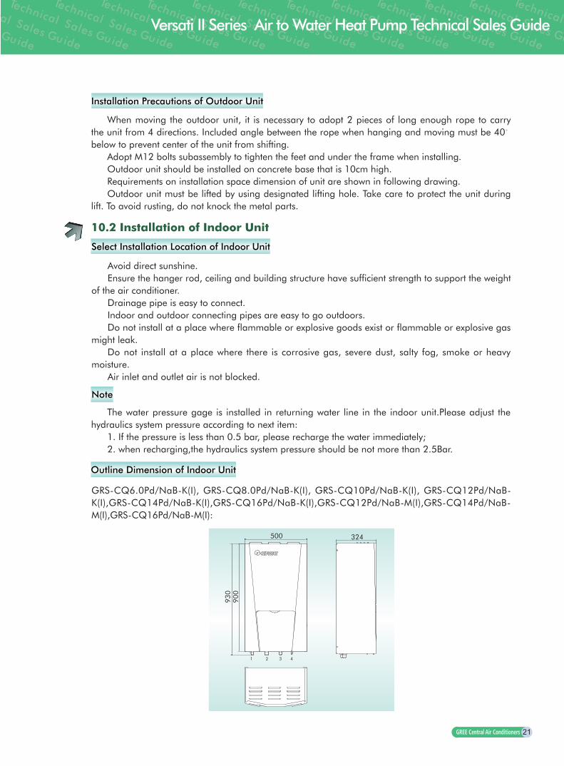
Select Installation Location of Indoor Unit
Outline Dimension of Indoor Unit
When moving the outdoor unit, it is necessary to adopt 2 pieces of long enough rope to carry the unit from 4 directions. Included angle between the rope when hanging and moving must be 40。
below to prevent center of the unit from shifting.Adopt M12 bolts subassembly to tighten the feet and under the frame when installing.Outdoor unit should be installed on concrete base that is 10cm high.Requirements on installation space dimension of unit are shown in following drawing.Outdoor unit must be lifted by using designated lifting hole. Take care to protect the unit during
lift. To avoid rusting, do not knock the metal parts.
10.2 Installation of Indoor Unit
Avoid direct sunshine.Ensure the hanger rod, ceiling and building structure have sufficient strength to support the weight
of the air conditioner.Drainage pipe is easy to connect.Indoor and outdoor connecting pipes are easy to go outdoors.Do not install at a place where flammable or explosive goods exist or flammable or explosive gas
might leak.Do not install at a place where there is corrosive gas, severe dust, salty fog, smoke or heavy
moisture.Air inlet and outlet air is not blocked.
The water pressure gage is installed in returning water line in the indoor unit.Please adjust the hydraulics system pressure according to next item:
1. If the pressure is less than 0.5 bar, please recharge the water immediately;2. when recharging,the hydraulics system pressure should be not more than 2.5Bar.
GRS-CQ6.0Pd/NaB-K(I), GRS-CQ8.0Pd/NaB-K(I), GRS-CQ10Pd/NaB-K(I), GRS-CQ12Pd/NaB-K(I),GRS-CQ14Pd/NaB-K(I),GRS-CQ16Pd/NaB-K(I),GRS-CQ12Pd/NaB-M(I),GRS-CQ14Pd/NaB-M(I),GRS-CQ16Pd/NaB-M(I):
324500
930
900
1 2 3 4
Note

22
Space Requirements of Installation
Pipe connection Unit: inch
No Name Remarks
1 Water Outlet Pipe 1 “ Male BSP
2 Water Inlet Pipe 1 “ Male BSP
3 Liquid-side Service Valve 3/8
GRS-CQ8.0/10/12/14/16Pd/NaB-K
GRS-CQ12/14/16Pd/NaB-M
1/4 GRS-CQ6.0Pd/NaB-K
4 Gas-side Service Valve 5/8
GRS-CQ8.0/10/12/14/16Pd/NaB-K
GRS-CQ12/14/16Pd/NaB-M
1/2 GRS-CQ6.0Pd/NaB-K
GRS-CQ6.0Pd/NaB-K(I), GRS-CQ8.0Pd/NaB-K(I), GRS-CQ10Pd/NaB-K(I), GRS-CQ12Pd/NaB-K(I),GRS-CQ14Pd/NaB-K(I),GRS-CQ16Pd/NaB-K(I),GRS-CQ12Pd/NaB-M(I),GRS-CQ14Pd/NaB-M(I),GRS-CQ16Pd/NaB-M(I):
200 1300 800
250
Service Space500
463
4 10
900
823
Mounting to Wall
unit outline
expansion bolt hole

23
Versati II Series Air to Water Heat Pump Technical Sales Guide
Indoor unit shall be vertically mounted on the wall of the room with expansion bolt.Keep the indoor unit away from heat sources like heat sink and so on in the room as much as
possible. Keep the indoor unit as close as possible to outdoor unit. Level distance between connection
pipes can not exceed 30m(8.0~16kW) or 20m(6.0kW) and vertical distance can not exceed 15m(8.0~16kW) or 10m(6.0kW).
10.3 Installation of Insulated Water Tank
Installation Measure
The insulated water tank should be installed and kept levelly within 5m and vertically within 3m from the indoor unit. It can be installed in the room.
Standing water tank must be installed vertically with the bottom on the ground, never suspended. Installation place must be firm enough and the water tank should be fixed on the wall with bolts to avoid vibration, as shown in the following figure. Weight capacity of water tank during installation should also be considered.
Fix with bolts
Water tank
Installed on the ground and never suspended
The minimum clearance from the water tank to combust ible surface must be 500mm.
There should be water pipe, hot water joint and floor drain near the water tank in favor of water replenishment, hot water supply and drainage of water tank.
Connec t ion o f in le t /ou t le t waterway: Connect the safety check valve attached with the unit (points at insulated water tank) with the water inlet of water tank with PPR pipe according to the following figure, sealing with unsintered tape. The other end of the safety check valve should connect with tap water joint. Connect the hot water pipe and water outlet of water tank with PPR pipe.
Tap water
Safety check valve

24
For safe use of water, water outlet/inlet of water tank must connect with a certain length of PPR pipe, L ≥70×R2(cm,R is inside radius of the pipe). Moreover, heat preservation should be conducted and metal pipe can not be used. For the first use, water tank must be full of water before the power is on.
Connection of Waterway System
If connection between water tank and indoor unit should be through the wall, drill a hole 70 for pass of circulating water pipe. It is unnecessary if the hole is not needed.
Preparation of pipelines: Circulating water outlet/inlet pipe must be hot water pipe, PPR pipe with nominal outer diameter of dn25. S2.5 series (wall thickness of 4.2mm) is recommended. Cooling water inlet pipe and hot water outlet pipe of water tank should also be hot water pipe, PPR pipe with nominal outer diameter of dn20. S2.5 series (wall thickness of 3.4mm) is recommended. If other insulated pipes are adopted, refer to the above dimensions for outer diameter and wall thickness.
Installation of circulating water inlet/outlet pipes: Connect the water inlet of unit with circulating outlet of water tank and water outlet of unit with circulating inlet of water tank.
Installation of circulating water inlet/outlet pipes: Connect the water inlet of unit with circulating outlet of water tank and water outlet of unit with circulating inlet of water tank.
Installation of water inlet/outlet pipes of water tank: Safety check valve (on the valve body points at water tank), filter and cut-off valve must be installed for water inlet pipe according to the installation sketch of unit. At least a cut-off valve is needed for the water outlet pipe.
Installation of blow-off pipe at the bottom of water tank: Connect a piece of PPR pipe with drainage outlet to floor drain. A cut-off valve must be installed in the middle of the drainage pipe and at the place where it is easy to be operated by the users.
After connection of all waterway pipelines, perform leakage test firstly (refer to debugging of the unit). After that, bind up the water pipes, water temp sensor and wires with wrapping tapes attached with the unit.
Refer to Installation Sketch of Unit for details.
temp sensor 2
Blow-off Outlet
Cut-off Valve
Tap water
FilterSafety check
valve
Hot water output
Water Tank
Temp Sensor 1
Indoor Unit
Cool Water Inlet
Power cord of booster heater
OtherThermal System
Other Thermal sensor (less than 5 meters)
Joints Dimension
Description Joint pipe thread (inch)
Circulating water inlet/outlet of main unit 1” Male BSP
Cooling water inlet of water tank 1/2” Fmale BSP
Circulating water inlet/outlet of water tank 3/4” Fmale BSP
Hot water outlet of water tank 1/2” Fmale BSP
Note
25
Versati II Series Air to Water Heat Pump Technical Sales Guide
Distance between main unit and insulated water tank should not exceed 5m levelly and 3m vertically. If higher, please contact with us. Water tank on lower and main unit on higher side is recommended.
Prepare the materials according to the above joints dimension. If cut-off valve is installed outside the room, PPR pipe is recommended to avoid freeze damage.
Waterway pipelines can't be installed until water heater unit is fixed. Do not let dust and other sundries enter into pipeline system during installation of connection pipes.
After connection of all waterway pipelines, perform leakage test firstly. After that, perform heat preservation of waterway system; meanwhile, pay more attention to valves and pipe joints. Ensure enough thickness of insulated cotton. If necessary, install heating device for pipeline to prevent the pipeline from freezing.
Hot water supplied from insulated water tank depends on pressure of water tap, so there must be supply of tap water.
During using, the cut-off valve of cooling water inlet of water tank should be kept normally on.
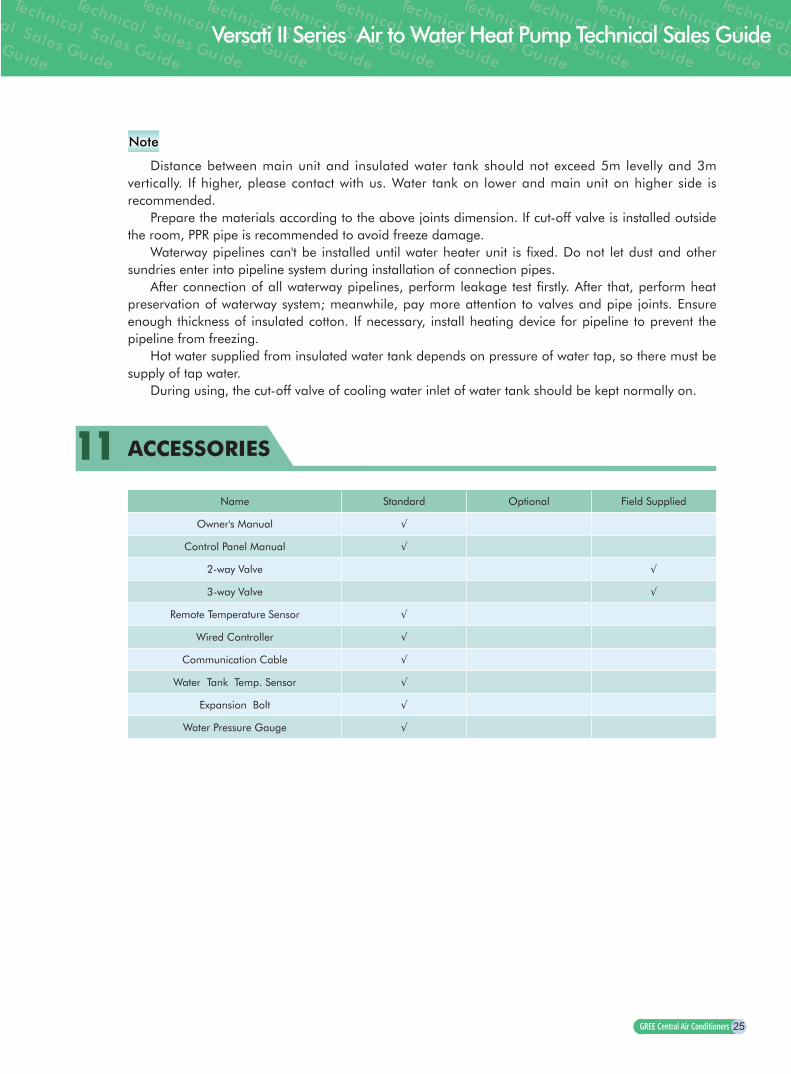
11 ACCESSORIES
Name Standard Optional Field Supplied
Owner's Manual √
Control Panel Manual √
2-way Valve √
3-way Valve √
Remote Temperature Sensor √
Wired Controller √
Communication Cable √
Water Tank Temp. Sensor √
Expansion Bolt √
Water Pressure Gauge √
Note

Add: West Jinji Rd,Qianshan Zhuhai,Guangdong,China519070Tel: (+86-756)8614883 Fax: (+86-756)8614998Http://www�gree�com Email: gree@gree�com�cnFor continous improvement in the products, Gree reserves the right to modify the product specification and appearence in this manual without notice and without incurring and obligations�
Gree Electric Appliances, Inc� of Zhuhai, founded in 1991, is the world's largest air
conditioner enterprise integrating R&D, manufacturing, marketing and services�
Technology Innovation and quality are always our priority� With efforts of
thousands of Gree's engineers, we own more than 3500 patents for our products�
Nowadays, we have 7 production bases in Zhuhai, Chongqing, Hefei and
Zhengzhou(China), as well as Brazil, Pakistan and Vietnam, with annual
production capacity of 30 million sets of residential air conditioners and 4 million
sets of commercial air conditioners�
With the installation of Gree commercial air conditioners in important projects at
home and abroad like Media Village for 2008 Beijing Olympic Games, Stadiums
for 2010 World Cup in South Africa, as well as India Telecom base station, Gree
commercial air conditioners are ready to develop steadily to every corner in the
world, to present a more comfortable and harmonious working environment and
family atmosphere�
GREE MAKING BETTER CONDITIONERS GREE MAKING BETTER CONDITIONERS GREE MAKING BETTER CONDITIONERS GREE MAKING BE
SJ00404099