Embed Size (px)
Citation preview

Aircraft Battery Testing Handbook
By Joseph F. Mibelli
V0.20 – 26 September 2016 (preliminary)
The information presented here is intended as a reference for the end users of equipment manufactured by JFM Engineering and in no way substitutes or supersedes the official information that battery manufacturers provide in their CMMs and OMMs.
JFM Engineering Inc. 8030 NW 67thStreet
Miami, Florida 33166, USA +1 305-592-2272 +1 305-599-6893
www.jfmeng.com
Copyright © 2016 - JFM Engineering
Aircraft Battery Testing Handbook V0.20
Page 2 of 36
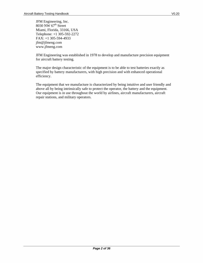
JFM Engineering, Inc. 8030 NW 67th Street Miami, Florida, 33166, USA Telephone: +1 305-592-2272 FAX: +1 305-594-4933 [email protected] www.jfmeng.com JFM Engineering was established in 1978 to develop and manufacture precision equipment for aircraft battery testing. The major design characteristic of the equipment is to be able to test batteries exactly as specified by battery manufacturers, with high precision and with enhanced operational efficiency. The equipment that we manufacture is characterized by being intuitive and user friendly and above all by being intrinsically safe to protect the operator, the battery and the equipment. Our equipment is in use throughout the world by airlines, aircraft manufacturers, aircraft repair stations, and military operators.
Aircraft Battery Testing Handbook V0.20
Page 3 of 36
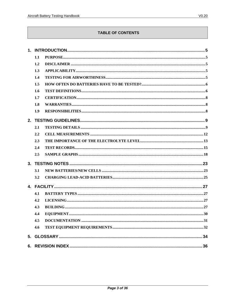
TABLE OF CONTENTS
1. INTRODUCTION ..................................................................................................................... 5
1.1 PURPOSE ................................................................................................................................................... 5
1.2 DISCLAIMER ........................................................................................................................................... 5
1.3 APPLICABILITY ...................................................................................................................................... 5
1.4 TESTING FOR AIRWORTHINESS ....................................................................................................... 5
1.5 HOW OFTEN DO BATTERIES HAVE TO BE TESTED?.................................................................. 6
1.6 TEST DEFINITIONS ................................................................................................................................ 6
1.7 CERTIFICATION ..................................................................................................................................... 8
1.8 WARRANTIES .......................................................................................................................................... 8
1.9 RESPONSIBILITIES ................................................................................................................................ 8
2. TESTING GUIDELINES .......................................................................................................... 9
2.1 TESTING DETAILS ................................................................................................................................. 9
2.2 CELL MEASUREMENTS ..................................................................................................................... 12
2.3 THE IMPORTANCE OF THE ELECTROLYTE LEVEL ................................................................. 13
2.4 TEST RECORDS ..................................................................................................................................... 15
2.5 SAMPLE GRAPHS ................................................................................................................................. 18
3. TESTING NOTES ................................................................................................................. 23
3.1 NEW BATTERIES/NEW CELLS ......................................................................................................... 23
3.2 CHARGING LEAD-ACID BATTERIES .............................................................................................. 25
4. FACILITY .............................................................................................................................. 27
4.1 BATTERY TYPES .................................................................................................................................. 27
4.2 LICENSING ............................................................................................................................................. 27
4.3 BUILDING ............................................................................................................................................... 27
4.4 EQUIPMENT ........................................................................................................................................... 30
4.5 DOCUMENTATION .............................................................................................................................. 31
4.6 TEST EQUIPMENT REQUIREMENTS .............................................................................................. 32
5. GLOSSARY .......................................................................................................................... 34
6. REVISION INDEX ................................................................................................................. 36
Aircraft Battery Testing Handbook V0.20
Page 4 of 36
TABLE OF FIGURES
Figure 1 – Short Term Charge Retention (SAFT OMM) .................................................................................... 11 Figure 2 – Position of Syringe in Cell Vent Seat (SAFT OMM)......................................................................... 13 Figure 3 – Insulation Leakage Test (SAFT OMM) ............................................................................................. 17 Figure 4 – First Capacity Test with one failed cell and several marginal cells .................................................... 18 Figure 5 – Second Capacity Test showing a good recovery ................................................................................ 18 Figure 6 – Apparent good Capacity Test with one bad cell ................................................................................. 19 Figure 7 – Charge Voltage failure and slight elevation of temperature ............................................................... 19 Figure 8 – Charge profile showing a significant elevation in battery temperature .............................................. 20 Figure 9 – Capacity Test and Charge failures ...................................................................................................... 20 Figure 10 – Good Charge Voltage and Cell Voltages profile .............................................................................. 21 Figure 11 – Charge Voltage profile showing the current delivered by the Charger-Analyzer ............................ 21 Figure 12 – Marginal first Capacity Test ............................................................................................................. 22 Figure 13 – Second Capacity Test showing a good recovery .............................................................................. 22 Figure 14 – Charger-Analyzer and Batteries placement ...................................................................................... 27
TABLE OF TABLES
Table 1 - Index of Revisions ................................................................................................................................ 36
Aircraft Battery Testing Handbook V0.20
Page 5 of 36
1. INTRODUCTION
1.1 PURPOSE
The purpose of this handbook is to provide guidelines for the testing of batteries used in aircraft.
1.2 DISCLAIMER
Information provided in this Handbook is a guideline intended for users of Battery Test Equipment manufactured by JFM Engineering and in no way replaces or supersedes information contained in the CMMs and OMMs as published by manufacturers of aircraft batteries, or instructions provided by airframe manufacturers and aircraft accessory manufacturers.
1.3 APPLICABILITY
Information provided in this Handbook is applicable in detail to Nickel-Cadmium batteries with some references provided for other types of batteries.
1.4 TESTING FOR AIRWORTHINESS
Batteries must be removed from the aircraft and bench tested to determine if they meet the requirements of the manufacturer1.
In this, batteries are no different from any other part of the aircraft.
Where is the importance? Batteries are part of the emergency system of the aircraft. In case of a power failure, the mainship battery is needed to start the APU (Auxiliary Power Unit) or simply to provide power to the 28V bus. In addition, many devices used in aircraft have their own emergency backup battery such as avionics and illumination equipment.
In case of such an emergency, it is expected that the battery will supply power for the time required to restore power generation or to directly power electrical and electronic devices until the aircraft is safely on the ground.
As an example, note that on January 8, 2008, a Qantas 747, lost all power generation while in route to Bangkok, Thailand. The crew was forced to use power from the backup battery to safely land the aircraft. In this case, the pilot counted on that the battery would supply the needed power. A properly tested battery will deliver power as needed2.
On a lesser note, an improperly serviced battery can result in a costly AOG as the aircraft will not be able to take off with battery problems.
One of the difficulties with battery testing is that batteries are heavy 3 and that they may not be located in the aircraft in places where it is easy for their removal and replacement. In addition, replacement batteries must be made available (extra expense). Hence, an opportunity for a resistance to test the batteries resulting in poorly maintained batteries. Also an opportunity to consider migration to Lead-Acid batteries because of their “easier” maintenance4,5
1 Requirements of the battery manufacturer and/or of the aircraft manufacturer or accessory manufacturer. 2 The aircraft manufacturer specifies the amount of current that the battery can supply and the amount of time
that it will last until exhausted. 3 60 to 80 lbs. (27 to 36 Kg) 4 Note that Maintenance Free is not to be equated with “care free” as Lead-Acid batteries also require a degree
of testing to determine their airworthiness. 5 Note that Lead-Acid batteries are not as powerful and rugged as Nickel-Cadmium batteries are. Also, Lead-
Acid Batteries can be damaged if allowed to deep discharge
Aircraft Battery Testing Handbook V0.20
Page 6 of 36
1.5 HOW OFTEN DO BATTERIES HAVE TO BE TESTED?
1.5.1. The frequency of testing of batteries is normally established by the aircraft manufacturer, appliance manufacturer or by the battery manufacturer. But, ultimately, the frequency of testing (testing intervals) is determined by bench test results, with reserve capacity, water level consumption, and cell imbalance being the governing figures.
1.5.2. When the testing interval is in excess of what it “should” be, the consequence is that cells may lose significant amounts of water (in excess of the maximum specified in the CMM) resulting in a degradation of cell separators. See more details under “The importance of Electrolyte Level” in section [0]. Also, cells will become so imbalanced that the battery will no longer be capable of delivering the required current, both of which will lead to premature cell/battery failure.
1.6 TEST DEFINITIONS
Note: Description of tests refers primarily to Nickel-Cadmium batteries. Additional comments are provided for Lead-Acid batteries.
1.6.1. Top Charge:
Top charge is the simplest type of service for all types of batteries. Batteries are "topped off" before being put on the aircraft to compensate for self-discharge while in storage.
Top charge is also used to determine the proper electrolyte level. Water is normally lost during usage and it is also lost due to evaporation. When the battery reaches full charge, the electrolyte is at its maximum level; distilled water6 is added as required.
The top charge process is also used to measure cell voltages, to determine that each cell reaches the proper charge voltage and to check if any cells exhibit a temperature rise and/or drop in their voltage under constant charge current (topping current).
Lead-Acid batteries are also top charged, and if of the flooded type, the specific gravity and level of electrolyte is also tested and adjusted as necessary. On sealed batteries, the specific gravity of the electrolyte cannot be measured.
1.6.2. Capacity Test:
This test determines if the battery will deliver the required current. After receiving a full charge, the battery is subjected for one hour to a typical discharge current of 100% of its rating. If none of the cells drop below 1V, the battery passes the capacity test. It is then recharged and returned to service.
If one or more of the cells drop below 1V, even if the battery as a unit does not drop below 20V (for a 20 cell battery) the battery fails the capacity test.
What happens next depends on the individual condition of the cells. If the cell voltages are reasonably similar (balanced), the battery is recharged and re-tested for capacity. If the cells are heavily unbalanced, then, the battery is subjected to a full discharge (deep cycle).
6 Or De-Ionized Water
Aircraft Battery Testing Handbook V0.20
Page 7 of 36
If after three tries, one or more cells fail to meet the capacity test, they are replaced. If more than 20% of the cells need to be replaced, it is recommended that either all the cells be replaced or that the entire battery be replaced (this is done to avoid a significant mixture of new and used cells).
Lead-Acid batteries are similarly tested for capacity, but with no individual cell readings (terminals for individual cells are not available).
1.6.3. Deep Cycle:
A battery where the cells are heavily unbalanced, either as received for testing or after failing a capacity test, must be fully discharged. This allows all cells to start from zero in the subsequent recharge, thus restoring the balance in the cell voltages7 .
Lead-Acid batteries are never discharged to zero during testing as this will result in irreversible damage.8
1.6.4. Overhaul:
Batteries are not repairable, at least not with the same meaning that we apply to other devices9.
The basic component of the battery is the cell (or cell block in a Lead-Acid battery).
If cells fail to perform, they are replaced. The same is true for other parts such as temperature sensors, connectors, links and fasteners.
A battery received for overhaul will get fully disassembled and washed. The cells will be checked for leakage (cracks).
Interconnecting hardware, (connectors, links, screws, nuts and washers), are normally cleaned. If burned, corroded, or otherwise deemed unsuitable, they are replaced.
1.6.5. Duration of Tests:
Battery testing is a lengthy process. It is important then, for customers to understand and accept that there is no such a thing as “quick turnaround” when testing batteries for certification10.
The longest test is the deep cycle because it involves many cycles of charge and discharge and this may require from 2 days to an entire week depending on the condition of the battery, as follows:
The first test on the battery is a capacity test to determine the as received charge state of the battery. Even though the capacity test is usually only one hour, the battery gets hot and has to be allowed to cool down (usually overnight) before it can be recharged11.
7 This cycle is repeated normally three times, if cells fail to “come up” to rated performance. 8 When Lead-Acid batteries are allowed to remain in a low charge state (below the minimum voltage), sulfation
will take place that will eventually render the battery useless 9 Batteries can only be “repaired” by replacement of non-conforming parts. 10 Any attempts to short circuit the process to reduce the turnaround time can easily result in incomplete testing
with all its negative consequences. 11 Since batteries are not expected to exhibit temperature increases during charge, it is then imperative for the
battery to be allowed to cool down before it can be recharged.
Aircraft Battery Testing Handbook V0.20
Page 8 of 36
Subsequent to the As Received Capacity Test, the battery is charged up, lasting four to six hours, depending on the manufacturer. A new capacity test can now be performed.
If it passes the capacity test and the cells are reasonably balanced, the battery can be recharged and eventually released.
If the capacity test fails, a total discharge needs to be performed. All cells are to be discharged to 0 volts12, followed by recharge and a new capacity test.
This cycle can be repeated up to three times to allow cells that may have failed capacity to get reconditioned.
1.7 CERTIFICATION
1.7.1. Certification of a battery means that the battery has passed all bench tests as specified by the manufacturer of the battery and can be returned to service.
Note that certification does not guarantee that a battery will function for a specific amount of time. However, the technician performing the test will be able to determine how “strong” the battery is and hence recommend if the battery will require replacement on a “short” period of time.
1.8 WARRANTIES
1.8.1. Warranties are provided by the manufacturers of the batteries, provided that the batteries are used and serviced in accordance to their specifications.
1.8.2. Equipment manufactured by JFM Engineering is designed to perform charge/discharge tests as required by the manufacturers of the batteries.
1.9 RESPONSIBILITIES
User’s Responsibility
It is the user’s responsibility to install power receptacles and electrical wiring in accordance with local codes.
It is the user’s responsibility to test batteries in accordance to the instructions and recommendations of the manufacturers of the batteries.
It is the user’s responsibility to observe all necessary precautions and to be equipped with personal protective equipment, when working with batteries to avoid injury due to electrolyte splashing, short circuits with tools and to avoid injury due to the size and weight of the batteries.
It is the user’s responsibility to operate the equipment within standard safety procedures applicable to the operation of a Battery Test Facility.
It is the user’s responsibility to operate the equipment within the limits and guidelines as described in the manuals.
It is the user’s responsibility to verify equipment suitability in the intended applications.
It is the user’s responsibility to verify the performance of the equipment and to operate and maintain them in accordance with the instructions in the manuals.
12 Using resistor clips and shorting clips
Aircraft Battery Testing Handbook V0.20
Page 9 of 36
2. TESTING GUIDELINES
2.1 TESTING DETAILS
There are two basic types of electrical tests that must be performed: Capacity and Charge Acceptance
2.1.1. Capacity Test
Supply of required current for a minimum time duration
Delivery of rated current (constant)
For one hour (typical). Some accessories have shorter test durations
The battery must remain above a minimum voltage
Battery Voltage Minimum = Number of Cells x Minimum Cell Voltage.
Cell Voltage 2.1.1.1.
Minimum: 1.00V
Marginal 1.00V to 1.05V
Acceptable: 1.05V to 1.10V
Good: above 1.10V
Note that if any of the cells falls below the minimum, the battery has failed the capacity test, even though the battery terminal voltage may be well above the required minimum.
2.1.2. Charge Acceptance
Transformation of input current into charge stored in the plates
Cell Voltage 2.1.2.1.
Under Constant Current conditions13 2.1.2.1.1.
Cell voltages are expected to increase continuously and 2.1.2.1.2.may appear to remain flat once the cells are well charged14.
Cell voltages must not droop15. 2.1.2.1.3.
Cells must achieve a minimum End Charge Voltage: 2.1.2.1.4.
Minimum: 1.50V
Typical: 1.55V to 1.65V
Maximum: 1.70V/1.75V
13 Charging with other than constant current will mask off cell performance issues. 14 Cell voltages are always climbing, albeit with an imperceptible slope, but they will rise abruptly once the cell
is fully charged. 15 Cell voltage droop is an indication of cell separator failure.
Aircraft Battery Testing Handbook V0.20
Page 10 of 36
2.1.3. Battery Temperature
The charging of Nickel-Cadmium cells is an endothermic process, meaning that under normal conditions, cells are not expected to have an increase in temperature.
In order to be able to determine if a battery is developing an appreciable warming, it is very important to perform all battery tests in a controlled environment where the temperature can be maintained below 30oC (86oF).
Equally important is to avoid freezing temperatures. Perform tests above 5oC (41oF).
If cells do heat-up during charge, it could mean the following: 2.1.3.1.
The cell is being overcharged
The cell is being charged at too high a rate for the A-Hr rating of the cell.
The cell could have a low electrolyte level16
There is a cell separator failure17
Note that older cells are expected to exhibit some warming due to their higher internal resistance.
Temperature rise levels: 2.1.3.2.
Typical: no appreciable warming (up to 5oC)
Appreciable warming: 5oC to 10oC
Overtemp: above 10oC
2.1.4. Battery Temperature Sensors
If the battery is equipped with Temperature Sensors they will have to be removed from the battery for testing.
Testing involves heating/cooling the sensor and to measure resistance or to measure opening and closing, as applicable to the type of sensor.
16 Too much water has evaporated 17 A cell with separator failure must be replaced (it is not repairable)
Aircraft Battery Testing Handbook V0.20
Page 11 of 36
2.1.5. Battery Storage after Testing
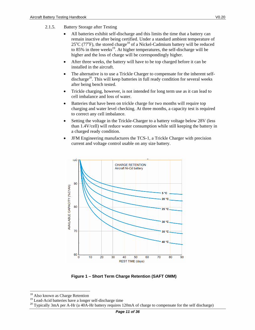
All batteries exhibit self-discharge and this limits the time that a battery can remain inactive after being certified. Under a standard ambient temperature of 25oC (77oF), the stored charge18 of a Nickel-Cadmium battery will be reduced to 85% in three weeks19. At higher temperatures, the self-discharge will be higher and the loss of charge will be correspondingly higher.
After three weeks, the battery will have to be top charged before it can be installed in the aircraft.
The alternative is to use a Trickle Charger to compensate for the inherent self-discharge20. This will keep batteries in full ready condition for several weeks after being bench tested.
Trickle charging, however, is not intended for long term use as it can lead to cell imbalance and loss of water.
Batteries that have been on trickle charge for two months will require top charging and water level checking. At three months, a capacity test is required to correct any cell imbalance.
Setting the voltage in the Trickle-Charger to a battery voltage below 28V (less than 1.4V/cell) will reduce water consumption while still keeping the battery in a charged ready condition.
JFM Engineering manufactures the TCS-1, a Trickle Charger with precision current and voltage control usable on any size battery.
Figure 1 – Short Term Charge Retention (SAFT OMM)
18 Also known as Charge Retention 19 Lead-Acid batteries have a longer self-discharge time 20 Typically 3mA per A-Hr (a 40A-Hr battery requires 120mA of charge to compensate for the self discharge)
Aircraft Battery Testing Handbook V0.20
Page 12 of 36
2.2 CELL MEASUREMENTS
Of all measurements on a battery under test, the most important one relates to the cells (each cell, individually). Although the total battery voltage is the important parameter inside the aircraft, for bench tests, the voltage on each of the cells determine the condition of the battery.
The number of measurements required is three at minimum: One at the beginning, one during and one at the end. More may be required depending on the condition of the battery.
It is, therefore, of high importance to have a proper method for measuring and recording cell voltages.
There are two methods for measuring and recording of cell voltages: manual and automated.
2.2.1. Manual Method
In the manual method, a digital voltmeter or digital multimeter is normally used. The probes are placed across each one of the cells (posts or links) and the voltage is measured (2V scale) and recorded.
Make sure that the voltmeter probes make good contact to obtain a reliable reading. Corrosion on the posts or links can often yield erroneous results (lower voltage). It may be necessary to clean the surfaces before measurements can be taken.
A suitable form is needed to do this where the voltage for each cell can be written in. Cell numbering can be from the most negative cell to the most positive cell or vice versa. The important point is that the method must be consistent.
Manual measurement and recording is laborious and error prone. Careful discipline must be exercised to insure that cells are accounted for in the proper order.
In addition, there is a limited time in which to effect the measurements. For the Capacity Test21, taking 20 or more readings at the end of the test22 may result in inaccurate voltages because voltages will be falling rapidly on a battery that has little or no capacity reserve. Considering that it may take more than one minute to read all voltages, cells measured first will show better voltages than those measured last. If a mistake is made, it may be necessary to redo the test23.
2.2.2. Automatic Method
In the automatic method, an electronic device automatically measures the voltages and records them for later retrieval, analysis and report printing.
Readings taken automatically are not subject to time limitations because all readings are taken at once, thus avoiding the differences between the first and last cells.
JFM Engineering manufactures the BATS16, a Computerized Battery Test and Analysis System that is designed to easily automate this process. This also provides easy retrieval for the data for analysis and reporting.
See BTAS16 sample graphs in section [2.5]
21 Normally a 60 minute test 22 Readings have to be taken while the battery is subjected to discharge current 23 No time to go back
Aircraft Battery Testing Handbook V0.20
Page 13 of 36
2.3 THE IMPORTANCE OF THE ELECTROLYTE LEVEL
Checking the electrolyte level is an integral part of the testing of the battery. Failure to do so will eventually result in premature cell failures. Note that the electrolyte level can only be checked at the end of the charge process.
Warning: Never use with Nickel-Cadmium batteries accessory devices that could be contaminated with Sulfuric Acid (from vented Lead-Acid batteries).
Warning: Unlike the need to measure the electrolyte concentration in Lead-Acid batteries, the electrolyte in Nickel-Cadmium batteries does not need to be measured or added (it is not an indicator of state of charge). Distilled water is the only addition to the electrolyte.
2.3.1. Water consumption
Nickel-Cadmium cells consume water as a normal part of their activity.
Water is consumed as a result of the in-flight charge process and when current is demanded from the battery as it occurs with the starting of engines or the APU.
The amount of water consumed is a measure of the activity of the battery.
When water is consumed beyond the levels given by the manufacturer of the battery, it is an indication that the battery must be serviced more frequently or that there is a possible electrical problem in the aircraft (overcharging).
If the battery is allowed to function with water levels below the minimum specified electrolyte level, then, in-flight battery overheating will be experienced. This in turn will contribute to an accelerated deterioration of the cell separator material and eventual cell failure.
When cells are operating with less than the minimum required electrolyte level, the active area of the plates is reduced hence forcing current over a smaller area (higher current density) resulting in an overheating of individual cells or the entire battery.
In extreme cases, this may result in a catastrophic in-flight failure (thermal runaway), a condition that requires that the battery be disconnected from the bus. Note that when a battery experiences an in-flight thermal runaway it will need to be replaced (new cells/new battery).
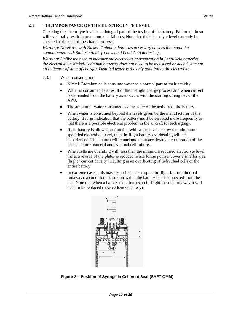
Figure 2 – Position of Syringe in Cell Vent Seat (SAFT OMM)
Aircraft Battery Testing Handbook V0.20
Page 14 of 36
2.3.2. Ground Service
When batteries are serviced, distilled water is added at the end of the charge and the amount of water delivered is recorded for each of the cells.
In the electrochemical process in the cells, water is absorbed by the plates during discharge and water is released during charge. It is for this reason that the only time when the electrolyte level can be tested and adjusted is at the end of the charge process (topping charge). Typically, when cells reach 1.6V or higher.
If water is added at a time other than at full charge, there is the danger that spilling of electrolyte will take place when the battery reaches full charge. When the water evaporates, there will be a conductive white residue24 deposited over the cell top, links and posts giving a clear indication of overfilling.
An exception to the when-to-add-water-rule is if a high cell voltage develops during charge (usually over 2V). This is an indication that the cell is “dry”. At this time, an injection of 5cc to 20cc will bring the cell voltages to normal levels.
It is also advised to initially dispense 5cc to 10cc on each cell for a battery that has a known history of high water consumption or if the battery has remained on the shelf for a prolonged period of time (over one year).
Uneven water consumption can be an indication of cell imbalance, cell age and cell damage.
Battery overheating during bench charging can be the result of low initial electrolyte levels.
The CMM for each battery/cell provides the basic information of consumable water level as a guide to determine when the electrolyte loss becomes excessive.
2.3.3. Summary
It is for all of these reasons that measurement and recording of water levels must be performed to obtain a more complete picture of the condition of the battery.
JFM Engineering offers a product called MasterFiller that greatly simplifies the task of adjustment of electrolyte levels.
24 Potassium Carbonate
Aircraft Battery Testing Handbook V0.20
Page 15 of 36
2.4 TEST RECORDS
Record keeping is an important part of battery testing. As batteries return to be serviced it is important to review prior test data to determine what might be expected from a new round of tests and to better analyze data that may help identify an impending battery failure.
The types of records are:
2.4.1. Test comparison25
If the battery received for testing has been tested before, it is very important to review prior results. A review of prior results will determine the degree of testing required. If the battery passed but did not perform well in the prior test, it is likely that the results of new tests will be worse. This comparison can result in significant time savings by not having to perform tests when it is known that the battery will fail.
2.4.2. As Received physical condition
Visual inspection of the physical condition of the battery26:
Integrity of the case and lid (including vent tubes, handles, latches, etc.)
Integrity of connector(s)
Integrity of links and hardware (including threads on the posts)
Evidence of hardware corrosion (green and blue spots)
Evidence of electrolyte leakage or overflow (potassium salt deposits; stains)
Evidence of overheating (overheated electrolyte odor)27
2.4.3. As Received Battery Voltage and Cell Voltages
Battery voltage and individual cell voltages must be recorded prior to performing any tests on the battery28.
2.4.4. As Received Leakage Test
Perform leakage tests from the positive and negative terminals to the case to determine if there are any cells that may have cracked bodies29.
2.4.5. Overhaul
Overhaul the battery (total disassembly) if there is evidence of cell leakage or electrolyte spills.
Replace any cells that may have cracks in their body.
25 JFM Engineering offers the BTAS16 where testing results are archived and available for easy comparison
with new test results. 26 If there is any evidence of damaged hardware, corrosion, etc. replacement is often the only solution. 27 Check the history of the battery and performance in the aircraft. A battery that has overheated could have
been operated low on electrolyte thus affecting the cell separators. 28 No current 29 Cells with cracks in their bodies must be replaced
Aircraft Battery Testing Handbook V0.20
Page 16 of 36
2.4.6. As Received Capacity Test
Performing an immediate Capacity Test provides an indication of how the battery is treated by the aircraft (provided that the battery is removed immediately after landing and that no appreciable current has been drained). This also provides a uniform starting point for the first charge.
More than likely, this Capacity Test will fail because the battery seldom arrives fully charged, but if it does, it may be an indication that this is a battery in very good condition.
The requirement here is to determine the degree of imbalance (if any). If there is more than a 50mV imbalance between cells, it is necessary to discharge each cell to zero (with resistors and/or clips) to allow the cells to achieve a fresh, balanced start.
Note also that although the cells may be well balanced, their end-of-test voltage may be too close to the bottom limit (less than 50mV reserve voltage). In this case, it is advised to deep cycle the cells and to observe if the reserve voltage has improved. If not, it may be an indication that the cells are reaching their end of life.
2.4.7. First Charge
The first charge will provide several clues as to the state of the cells in the battery. If cells heat-up at the beginning of the charge, it could be a sign of lack of water. More significantly if any of the cells rises prematurely and in some cases as high as 2V or even more this is a sign of a “dry” cell. Consequently, it is necessary to add some water (5cc to 10cc to all cells if needed) until the situation is remedied.
As the cells charge, the voltage will remain at 1.4V to 1.45V for most of the Main Charge (and even into the Topping Charge) and will eventually rise to and pass 1.50V towards an end charge voltage of 1.60V to 1.65V per cell.
If any of the cells reach this voltage but later the voltage drops back, then this is an indication that there is separator damage requiring that the cell be replaced. Note that no amount of exercising will remedy this condition. On the contrary, continued testing will result in a further voltage drop30.
2.4.8. Water Level
At the completion of the first charge (actually, during the last few minutes of the charge cycle) the level of the electrolyte must be checked and corrected as necessary by the addition of distilled water (or de-ionized) to the level specified in the CMM31.
2.4.9. First Capacity Test
The first Capacity Test will provide the first indication of the condition of the battery. If it passes the test, determine the reserve voltage and degree of imbalance as per [2.4.4] and either discharge fully or recharge.
If the battery does not pass this first Capacity Test, it can be repeated up to three times to allow the cells to recover their specified capacity.
2.4.10. Second Charge
See [2.4.7] for details
30 A cell with separator failure must be replaced (it is not repairable) 31 Note that the water level test can only be performed at the end of a charge cycle. This is when the electrolyte
level is at its highest.
Aircraft Battery Testing Handbook V0.20
Page 17 of 36
2.4.11. Perform additional Discharge and Charge cycles, as required to restore the performance of the battery
When the battery does not pass its first capacity test (normal) or does not appear to charge properly (i.e., takes too long for the cell voltages to increase, or cells are highly imbalanced at the end of the charge cycle), additional charge/discharge cycles should result in an improvement. If there is no appreciable improvement, then cells can be considered to be at the end of their useful life.
2.4.12. Torque Check
Check the torque of the hardware holding the links.
2.4.13. Vent Cap Check
Wash the Vent Caps to remove any Potassium Salt residues and check for the integrity of the O-Ring.
Test the valve in the Vent Cap to verify that it opens and closes in the specified pressure range. Replace any Vent Caps that do not pass the pressure test.
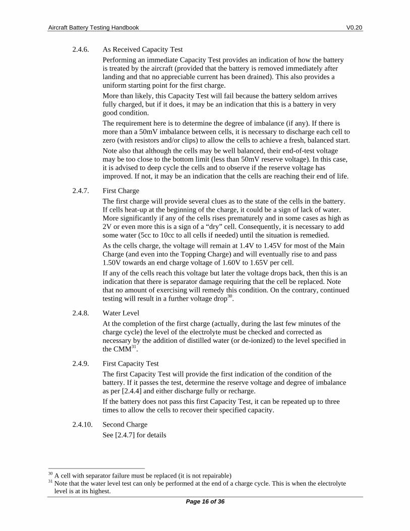
2.4.14. Final Insulation Test (Leakage Test)
Perform leakage tests from the positive and negative terminals to the case. Caution! Do not connect between the battery terminals as this will destroy the measuring device.
Figure 3 – Insulation Leakage Test (SAFT OMM)
2.4.15. Archival of Test Records
Once a test has been completed it is important to archive the test results as needed for comparison of new/old tests and/or for possible audit trail requirements.
2.4.16. Samples of Battery Test Graphs32
See samples of various battery tests in section [2.5]
32 Graphs are taken from our BTAS16 system
Aircraft Battery Testing Handbook V0.20
Page 18 of 36
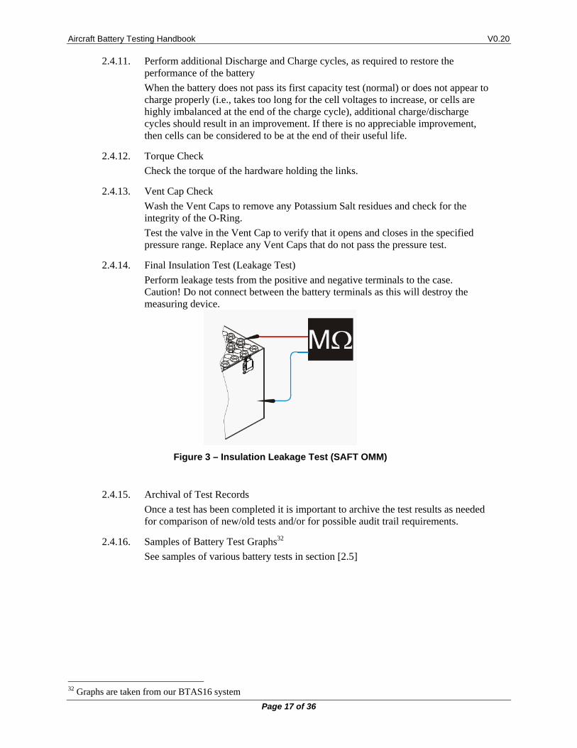
2.5 SAMPLE GRAPHS
Example of test results as recorded by the BTAS16 Battery Test and Analysis System
Figure 4 – First Capacity Test with one failed cell and several marginal cells
Figure 5 – Second Capacity Test showing a good recovery
Aircraft Battery Testing Handbook V0.20
Page 19 of 36
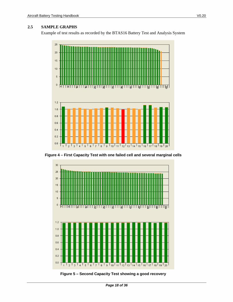
Figure 6 – Apparent good Capacity Test with one bad cell
Figure 7 – Charge Voltage failure and slight elevation of temperature
Aircraft Battery Testing Handbook V0.20
Page 20 of 36
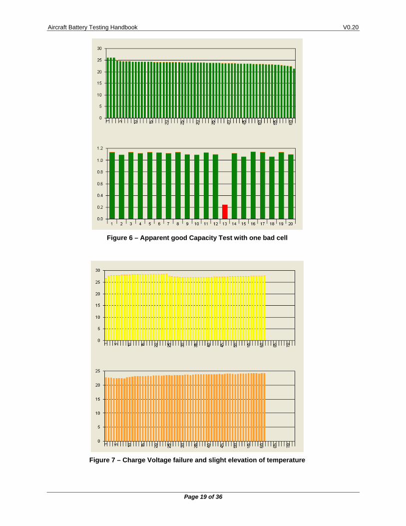
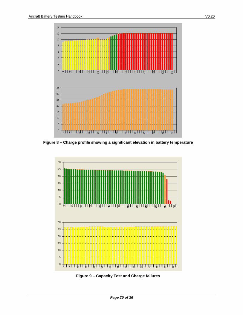
Figure 8 – Charge profile showing a significant elevation in battery temperature
Figure 9 – Capacity Test and Charge failures
Aircraft Battery Testing Handbook V0.20
Page 21 of 36
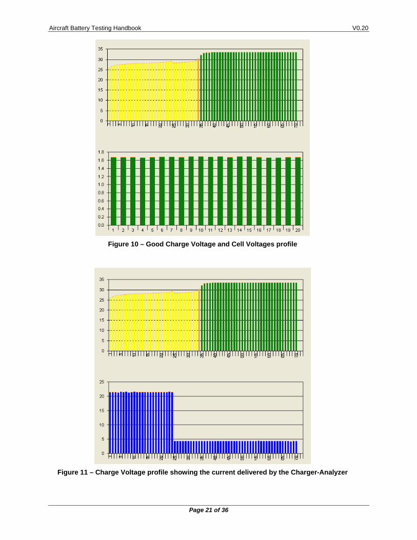
Figure 10 – Good Charge Voltage and Cell Voltages profile
Figure 11 – Charge Voltage profile showing the current delivered by the Charger-Analyzer
Aircraft Battery Testing Handbook V0.20
Page 22 of 36
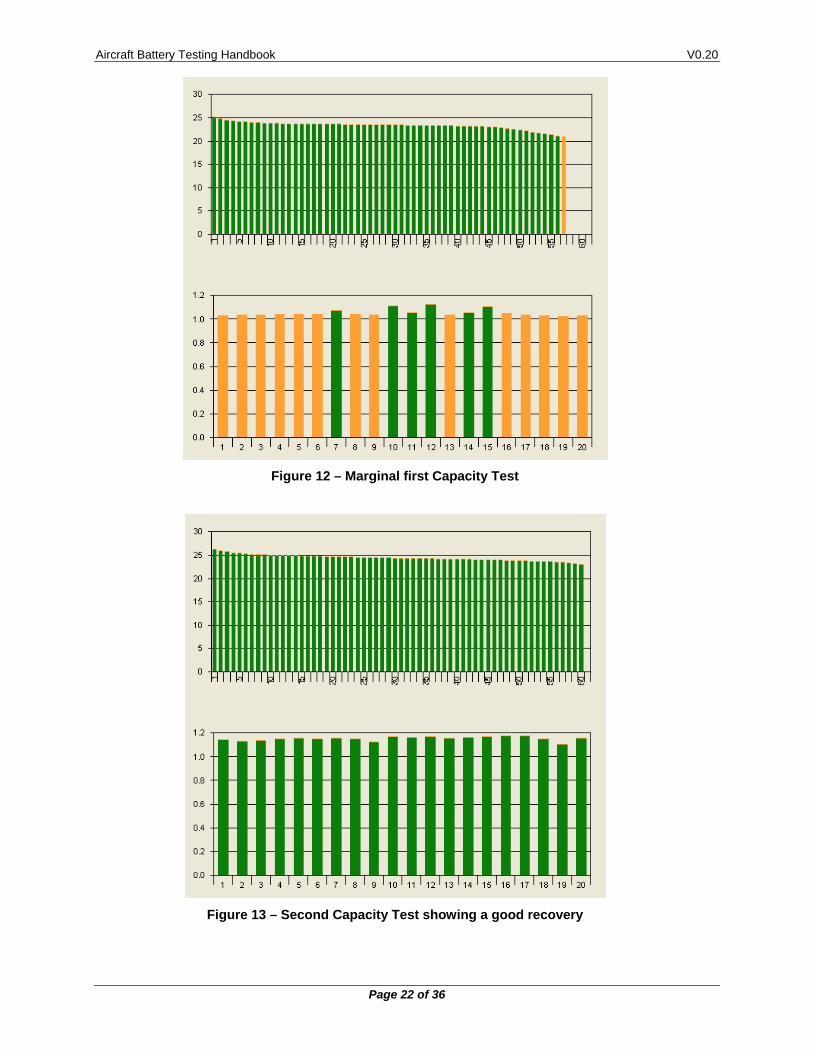
Figure 12 – Marginal first Capacity Test
Figure 13 – Second Capacity Test showing a good recovery
Aircraft Battery Testing Handbook V0.20
Page 23 of 36
3. TESTING NOTES The following are general notes on various testing details of batteries
3.1 NEW BATTERIES/NEW CELLS
3.1.1. New Batteries
Inspect the batteries for proper installation of cells and links. 3.1.1.1.
If a cell is installed reversed, the battery voltage will be lower than expected when subjected to a charge current (21V as opposed to 24V for a 20 cell battery).
Charging under these conditions may damage the cell installed in reverse.
Batteries are shipped from the factory completely discharged, often 3.1.1.2.with a shorting spring loop around the posts of the battery connector. This is done to maintain the battery voltage at zero.
Remove the shorting spring prior to attempting a charge.
Apply a small amount of charge current (less than C/10) and observe that all cells react properly (somewhat rapidly up to 1.2V and with a slower voltage increase thereafter).
If this initial test is OK, proceed with charging as recommended in the CMM (in most cases, two hours of Main followed by two or four hours of Topping).
Note that new cells may not surpass 1.55V (or even 1.5V) on the first charge. Many new cells will not achieve the 1.55V minimum until after several charge /discharge cycles.
3.1.2. Old Batteries
An old battery is one that is at the limit of its service or that has aged prematurely due to abuse/misuse.
Old batteries are characterized by the following performance features: 3.1.2.1.
Higher cell voltages during charge due to the higher internal resistance
Some temperature increase during charge (due to the higher internal resistance). Normal, if the temperature increase does exceed 5oC
Imbalance in the voltages of the cells, mostly during Capacity Test. Normal, but if it cannot be improved with a deep discharge then the cells/battery have reached their life limit.
Reduced Capacity Reserve33 during the Capacity Test.
Note that if during charge any cell fails to reach at least 1.55V (typically 1.6 to 1.65V), the cell could have separator damage. Typically, an affected cell will not exceed 1.45V and sometimes may actually drop to a much lower value or to a complete short. Cell replacement is the only solution.
33 Capacity Reserve is the difference between the measured cell/battery voltage and the Capacity Failure
Voltage (1V/cell).
Aircraft Battery Testing Handbook V0.20
Page 24 of 36
3.1.3. Abandoned Batteries
An abandoned battery is one that has been inactive for 12 months or more.
Depending on environmental conditions, mostly temperature, the effects on inactivity can occur in as early as 6 months.
Unless stored completely discharged (shorted), batteries will degrade with inactivity and will require special test cycles to bring them back to acceptable performance.
Start by measuring if there is any residual voltage in the cells. If not 3.1.3.1.completely discharged, it will show a wide range of voltages from cell to cell. This is normal.
Do not attempt to charge at full current34. 3.1.3.2.
Rather, apply an initial low current (lower than C/10) and observe the voltages on each of the cells.
If any of the cell voltages goes very high (approaching or exceeding 2V), then the cell is “dry”.
Apply a small amount of distilled water (a few cc) and observe that the voltage goes down to about 1.2V. Add more water as needed.
When all cells show a proper voltage (about 1.2V), set the Charger-Analyzer for a C/10 charge for 14 hours. Monitor the battery voltage and look for an abnormal temperature rise (greater than 10oC). If an overtemperature is observed, one or more cells may have Cell Separator damage requiring that the effected cells be replaced (they are not repairable).
Note that Charger-Analyzers manufactured by JFM Engineering utilize a Temperature Plate to monitor the temperature of the battery during charge and to shut down the charging if an abnormal temperature increase is observed.
JFM Engineering also offers a Battery Test System35 that monitors and records the voltages of the cells, thus facilitating the rehabilitation of the battery.
Subsequently, the battery needs to be discharged (Capacity Tested) and then it can be re-charged at the normal Main/Topping rates.
Note that if any cell fails to reach at least 1.55V (typically 1.6 to 1.65V) after charging, the cell could have separator damage. Typically, an affected cell will not exceed 1.45V and sometimes may actually drop to a much lower value or to a complete short. Cell replacement is the only solution.
34 Charging at full current an “abandoned” battery will cause it to overheat 35 BTAS-16
Aircraft Battery Testing Handbook V0.20
Page 25 of 36
3.2 CHARGING LEAD-ACID BATTERIES36
Charging of Lead-Acid Batteries is relatively straight forward (with the right equipment … )
Note that Charger-Analyzers manufactured by JFM Engineering are designed to service Lead-Acid batteries in all test modes with great precision.
3.2.1. Set the Voltage (typically about 28V for a 24V battery), set the current to a maximum value as recommended by the battery manufacturer and set the time as needed to achieve full charge.
3.2.2. Upon starting the charge, the voltage should slowly rise and settle to the programmed value.
Immediately after, the charge current will begin to drop while the battery voltage remains at the selected value (this is a typical response of constant voltage chargers).
The charge current will continue to drop and will eventually settle to a very low value, or change very little, (about 3% of the rating of the battery). When the charge current reaches this level, the battery can be considered fully charged.
Note that as the battery ages the current at the end of the charge will rise, eventually indicating that the battery is reaching its service limit.
3.2.3. Abnormalities
The most common abnormalities in Lead-Acid batteries are wear-out of the plates, plate oxidation and plate sulfation.
Plates wear-out is simply a product of the use of the battery. As the 3.2.3.1.battery ages, the internal resistance of the battery increases, eventually to a level where the battery can no longer deliver the required current.
Plate oxidation is the result of battery overcharging. Oxidation is an 3.2.3.2.irreversible loss of active area in the plates leading to a premature failure.
Plate sulfation is the result of allowing a battery to self-discharge to 3.2.3.3.below 1.8V/cell (21.6V for a 24V battery).
The sulfation creates a high resistance in the plates which will not allow charging, regardless of how long the battery is connected to the charger.
Depending on the degree of sulfation, it is possible to reverse it, that is, to force the sulfate to go back into solution, but it is not possible to determine if the recovery will be complete.
A worn out battery may show an acceptable voltage but may develop an abnormally high voltage when charged with constant current (and will fail the capacity test) whereas a sulfated battery will show an abnormally low voltage to begin with.
To determine if a battery is sulfated, apply a very low current (C/100 or less) from a constant current charger capable of about twice the voltage of the battery being tested. Observe the battery voltage.
36 See Document # 5-0171 from Concorde Battery Corporation for detailed information on their batteries,
Document Q01-1100 from Gill (Teledyne Battery Products) for detailed information on their batteries.
Aircraft Battery Testing Handbook V0.20
Page 26 of 36
If the voltage rises immediately, the battery is definitely sulfated. If the voltage later starts to go down, then sulfation is being corrected. As the voltage continues to go down, it should be possible to increase the current to accelerate the process.
The de-sulfation process is long (could be more than 24 hours) but it should render a usable battery. When the battery voltage reverses direction, the sulfation is complete and the current is now charging the battery.
Upon a full charge, the battery needs to be capacity tested to determine its condition (note that it may not recover 100% capacity).
3.2.4. Reconditioning37
Lead-Acid batteries can suffer from cell imbalance, similar to Nickel-Cadmium batteries. But, unlike Nickel-Cadmium, Lead-Acid batteries cannot be deep discharged. In their case, cells can be “balanced” by allowing the total battery voltage to reach a level higher than the normal CV value thus allowing each cell to reach a higher voltage.
37 See Service Bulletin CBC-SB-09302014-1B from Concorde Battery Corporation
Aircraft Battery Testing Handbook V0.20
Page 27 of 36
4. FACILITY The following are guidelines to establish a facility to test and certify batteries used in aircraft.
4.1 BATTERY TYPES
Applicable to all types of batteries
4.2 LICENSING
Before Airworthiness Certifications for the batteries can be generated, the shop has to be licensed by the FAA (part 145), EASA or other applicable Aviation Agency, either as a stand-alone operation or as part of a larger repair station.
4.3 BUILDING
4.3.1. Building Codes
The Battery Test Facility requires compliance with local regulations concerning electrical wiring, ventilation, plumbing and safety.
4.3.2. Floor space
Floor space is dictated by the size of the operation. The basic requirement is to have space for benches to perform electrical tests, benches to assemble/dis-assemble batteries, desks, files and batteries/parts storage.
4.3.3. Bench Space
One 8 foot (2.44 meters) bench can handle up to three Battery Testing Stations38 but it is best to have only two Battery Testing Stations and allow a middle area to be used to move batteries around.
One extra bench needs to be dedicated for the disassembly and assembly of batteries so as not to interfere with batteries under test.
Benches are required to be of strong construction due to the combined weight of the batteries and the weight of the Charger-Analyzers.
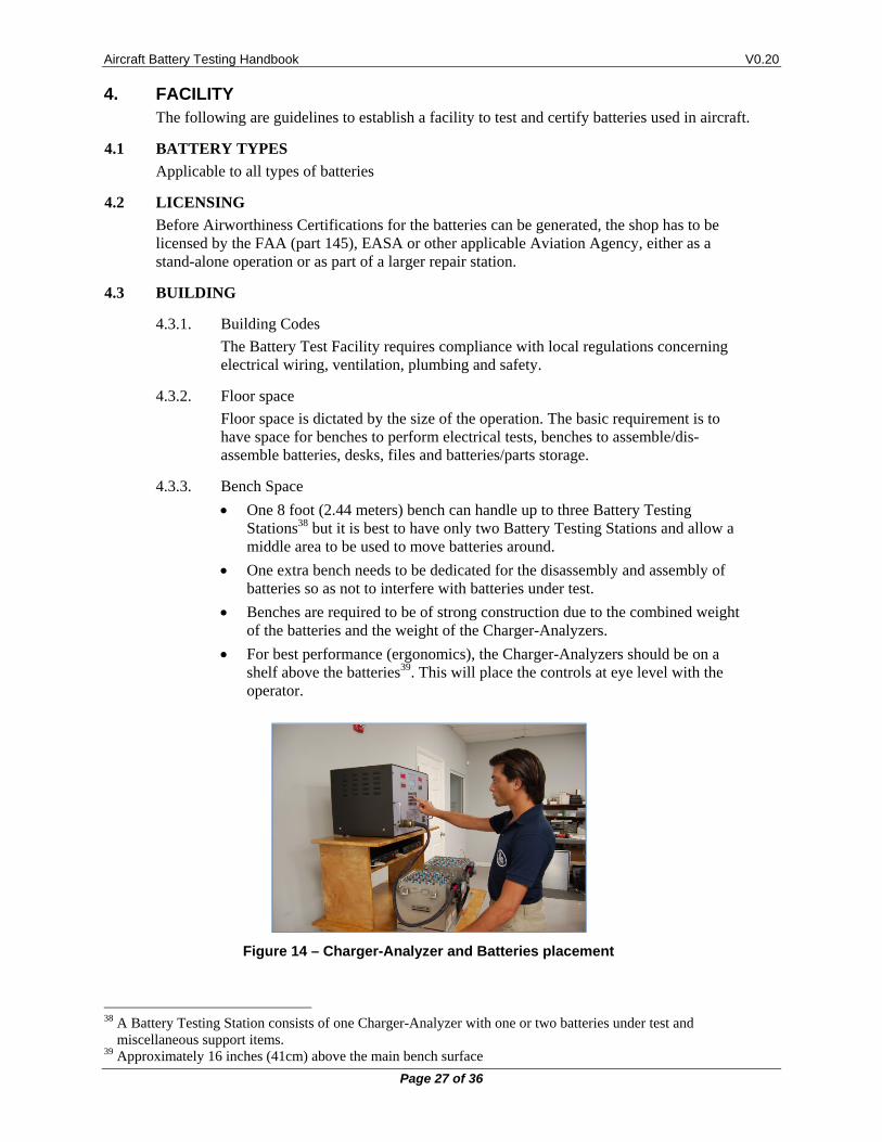
For best performance (ergonomics), the Charger-Analyzers should be on a shelf above the batteries39. This will place the controls at eye level with the operator.
Figure 14 – Charger-Analyzer and Batteries placement
38 A Battery Testing Station consists of one Charger-Analyzer with one or two batteries under test and
miscellaneous support items. 39 Approximately 16 inches (41cm) above the main bench surface
Aircraft Battery Testing Handbook V0.20
Page 28 of 36
4.3.4. Electrical
The Electrical supply has to have ample capacity for each of the Battery Test Stations. This requires individual supply circuits (not shared), capable of 30A at 208/230/240V with their own overcurrent protection (motor load rated circuit breakers).
4.3.5. Plumbing
A small sink with drain is required to wash cells after a battery disassembly.
Note that battery electrolyte (Potassium Hydroxide) must not be released into the sewer. It must be collected and disposed in accordance with local environmental regulations.
4.3.6. Ventilation
Nickel-Cadmium batteries emit gasses during charge, particularly during the topping stage. Suitable ventilation in the form of extraction fans, with or without hoods, is necessary to eliminate those fumes.
A small fan may also be required to dissipate areas of concentrated fumes and to remove the hot air generated by the Charger-Analyzers, particularly during discharge tests.
4.3.7. Compressed Air
A source of compressed air is needed to help with the cleaning of batteries that may have a deep accumulation of Potassium Carbonate (white residue) on cells and links.
Compressed air is also needed for the testing of valves in the vent caps (with their own regulated air pressure).
Protect eyes when using compressed air.
4.3.8. Storage
Storage areas are required for batteries, cells and other replacement parts.
Also, for batteries awaiting to be serviced or ready to be delivered to customers.
4.3.9. Safety
Batteries are heavy and are capable of very high discharge rates if shorted. We recommend that batteries be moved laterally between benches and carts and to use a lifter capable of picking-up batteries from the floor to place them on carts and benches. Carts and benches should have identical heights to facilitate movement and minimize personal effort.
Nickel-Cadmium batteries have a strong alkali in their cells that requires the use of personal protective equipment (gloves, goggles, etc.)
Lead-Acid batteries (the non-sealed type) have a strong acid in their cells, also requiring personal protective equipment (apron, gloves, goggles, etc.).
Note that non sealed Lead-Acid batteries are not permitted to be in the same area where Nickel-Cadmium batteries are tested. Only sealed types are permitted.
Some tools require insulation to prevent/minimize the possibility of short circuits on batteries with exposed cell links.
Aircraft Battery Testing Handbook V0.20
Page 29 of 36
4.3.10. Tools
Standard Tools
Socket and ratchet tool sets
Torque Wrenches40
Plastic/rubber head hammers
Miscellaneous other tools and chemicals
4.3.11. Special Tools41
Cell Pullers 4.3.11.1.
Required to remove (pull-out) cells from the batteries
Syringes for distilled water dispensing 4.3.11.2.
Required to replenish distilled water in the cells
JFM Engineering manufactures the MasterFiller, designed to facilitate the task of delivering42 and recording the distilled water required by each of the cells.
Vent Cap Wrenches 4.3.11.3.
Resistor clips 4.3.11.4.
Implemented with 1 ohm43 5W or 10W resistors with suitable clips
Required to individually discharge each of the cells
Shorting clips 4.3.11.5.
Required to individually short each of the cells after being discharged to less than 0.5V
Petroleum Jelly 4.3.11.6.
Petroleum Jelly is used to protect links posts, and hardware from corrosion44.
40 Used to tighten the nuts that hold the links on the cells 41 Most special tools are available from battery manufacturers and are made available through Aviation
Distributors. 42 With electronic level sensing 43 The actual value is inconsequential 44 The electrolyte will react with exposed copper leaving green and blue deposits.
Aircraft Battery Testing Handbook V0.20
Page 30 of 36
4.4 EQUIPMENT
Note that all equipment, including some tools, is subject to yearly calibration/certification.
4.4.1. Charger-Analyzers
For Mainship Batteries 4.4.1.1.
Equipment capable of charging and discharging in the 40A to 60A region.
JFM Engineering manufactures the SuperMasterCharger, an advanced capability Charger-Analyzer specifically designed for 10AHr to 100AHr batteries and their specific testing requirements.
The SuperMasterCharger is also available with extended discharge capabilities: up to 80A for one battery and up to 40A for two batteries (limited electronically by power dissipation).
For Emergency Batteries and Small Battery Packs 4.4.1.2.
Equipment capable of charging in the 2A region and discharging in the 10A region.
JFM Engineering manufactures the MiniMasterCharger, an advanced capability Charger-Analyzer specifically designed for small batteries (up to 10AHr) and their specific testing requirements.
4.4.2. Test Equipment
Multimeter 4.4.2.1.
A standard 3-1/2 digital voltmeter is required to measure cell voltages and overall battery voltage.
Note that JFM Engineering manufactures the BTAS16 system to automate the process of taking cell readings and other battery parameters.
Insulation Tester 4.4.2.2.
An insulation tester is required to determine that cells do not have defects in the nylon cases where electrolyte can leak.
Reference Voltmeter 4.4.2.3.
Required for calibration of the Charger-Analyzer
Reference Ammeter 4.4.2.4.
Required for calibration of the Charger-Analyzer
Note that JFM Engineering manufactures the VCM-100, an instrument 4.4.2.5.designed for verification and calibration of Battery Charger-Analyzers
Aircraft Battery Testing Handbook V0.20
Page 31 of 36
4.5 DOCUMENTATION
4.5.1. CMMs and OMMs45
Manufacturer’s data on Batteries and Cells.
This is required before any work is to be performed on a battery
4.5.2. Test Records46
Written/Printed Records of all inspections and tests performed in each of the batteries.
Note that the BTAS16 from JFM Engineering generates printed reports of all tests performed and that it can archive electronically, all accumulated data for easy retrieval and comparison at any time.
45 CMMs and OMMS are easily obtained through the Internet 46 Test records are to be retained for a minimum period of time as determined by the applicable Air Agency
requirements.
Aircraft Battery Testing Handbook V0.20
Page 32 of 36
4.6 TEST EQUIPMENT REQUIREMENTS
The choice of test equipment is extremely important because equipment must be capable of testing the battery exactly as specified by the manufacturer of the battery.
It must also be easy to use, reliable, easy to maintain and safe.
4.6.1. Safety
Safety is of extreme importance. The Charger-Analyzer is normally capable of very high currents at moderate to high voltages.
Charger-Analyzers manufactured by JFM Engineering are intrinsically safe and will protect the operator, the battery and the equipment in a variety of conditions such as Reverse Polarity, Short Circuit, Open Circuit, Overtemperature, Overheat, Overvoltage and Overcurrent.
Internal Charge/Discharge fuses and a mains Circuit Breaker complete the protection system.
4.6.2. Constant current
Battery manufacturers specify that all charge and discharge tests be performed with constant current.
There are many methods to simply charge a battery but it is important to determine that the purpose of the Charger-Analyzer is to be able to test the ability of the cells to transform the charge current into charge stored in the plates and this can only be determined properly when constant current is applied.
Equally important is the use of constant current for the Capacity Test, as opposed to using a passive load47.
4.6.3. Programmable test parameters
The Charger-Analyzer must also have the flexibility needed to test a wide variety of batteries. Aircraft batteries are available with a wide range of A-Hr capability and number of cells, and the Charger-Analyzer must be capable of handling all types equally well.
4.6.4. Voltage control and voltage limits
Although the charge/discharge methods require constant current, there are occasions when voltage control is needed for the charging of Sealed Lead-Acid batteries.
In addition, it is necessary to be able to detect undervoltage condition as in Capacity Tests. Also overvoltage conditions that could be the result of overcharging, dry cells or too high a current for the size of the battery.
A peak detecting capability is also useful when performing accelerated charging at 1C48
4.6.5. Internal Temperature Monitoring
When batteries are discharged there is a high dissipation in the load bank. If cooling were to become insufficient this could damage the load bank. Hence, the need for internal temperature monitoring and automatic shutdown.
This is also applicable to the charge process (although to a lesser degree), due to transformer and semiconductor heating.
47 Lamps or resistors 48 Transfer from Main to Topping at a peak voltage
Aircraft Battery Testing Handbook V0.20
Page 33 of 36
4.6.6. Battery Temperature Monitoring
As stated before, batteries are not supposed to heat-up during charge. If so, charging needs to be halted to avert a destructive thermal runaway. Therefore, it is extremely important for the Charger-Analyzer to be able to monitor the temperature of the battery and to shut-off the charge to prevent any further damage.
4.6.7. Ease of use
A Charger-Analyzer, while complex because of all of its functions must remain easy to use. The controls must be user friendly and intuitive to permit efficient operation with a minimum of difficulty and training.
Aircraft Battery Testing Handbook V0.20
Page 34 of 36
5. GLOSSARY Battery Manual: General Technical information provided by a manufacturer applicable to
a series of batteries. See Also CMM and OMM.
Battery Test Profile: A specific group of parameters for a specific type of test (i.e., Time, Current and Voltage).
BTAS16: A computerized Battery Test System manufactured by JFM Engineering.
Capacity Test: Test performed to determine if a battery can deliver the advertised, specified or required amount of current.
Cell Imbalance: The difference of voltage from cell to cell at the end of a Capacity Test or Charge.
Charge Acceptance: The capability of the cells to transform the incoming current into charge stored in the plates.
CMM: Component Maintenance Manual - Technical information provided by a manufacturer for a specific battery.
Constant Current: As applicable to a charge or discharge test, a current that remains within a few percent of a center value, independent of battery voltage, temperature or line voltage (mains). This is the preferred charge/discharge method for Nickel-Cadmium batteries.
Constant Voltage: As applicable to a charge test, a voltage that remains within a few percent of a center value. In this case, as the battery is charged the current is automatically decreased by the charger to maintain the voltage at the required level. This is the typical charge method for Lead-Acid batteries. Note that in the aircraft, the charge method is constant voltage, regardless of the type of batteries used.
C-SCAN: A Data Acquisition Terminal (part of the BTAS16)
Deep Cycle: As applicable to Nickel-Cadmium batteries, the process of discharge to zero for each of the cells, done to equalize the cells.
Electrolyte Level Test: As applied to Nickel-Cadmium cells that have a vent cap, the process of verifying the level of the electrolyte and the addition of distilled water as required (Note that this test is performed only at the end of a charge cycle).
Full Discharge: Constant Current Discharge with no voltage limit (discharged first by the Charger-Analyzer and finished by resistors and shorting clips).
Lead-Acid: Chemistry system of batteries used for most stand-by applications and for applications demanding less severe discharge currents than with Nickel-Cadmium.
Main Charge: As applicable to Nickel-Cadmium batteries, the C/2 charge current that provides 100% of the A-hr rating.
MiniMasterCharger: A Charger-Analyzer for Emergency Battery Packs manufactured by JFM Engineering.
Nickel-Cadmium: Chemistry system of batteries as used in aviation and other heavy duty applications.
Overhaul: The process of disassembly of all interconnections, cleaning/replacement of interconnecting hardware, removal of cells and cleaning of cells and the interior of the battery. This is applicable to batteries that are made up from an interconnection of multiple cells.
Reserve Capacity: The difference between the Capacity Test Voltage and the minimum voltage for each of the cells.
SLA: Sealed Lead-Acid Battery
Aircraft Battery Testing Handbook V0.20
Page 35 of 36
SuperMasterCharger: A Charger-Analyzer for Mainship Batteries manufactured by JFM Engineering.
TCS-1: A trickle Charger manufactured by JFM Engineering.
Temp-Plate: A plate used to measure the temperature of batteries under test.
Thermal Runaway: Destructive condition under constant voltage charging where one cell fails and heats up and causes all other cells to fail by the transmission of heat from one cell to the next. The drop in internal voltage causes an increase in charge current that intensifies the heating, thus accelerating the process.
Topping Charge: As applicable to Nickel-Cadmium batteries, the C/10 charge current that provides 40% of the A-Hr rating (after the Main Charge)
VRLA: Valve Regulated Lead-Acid Battery
Water Leveling: The process of bringing the electrolyte level to the prescribed level by the addition of distilled water (or de-ionized).
Aircraft Battery Testing Handbook V0.20
Page 36 of 36
6. REVISION INDEX
Table 1 - Index of Revisions
REVISION DATE NOTES V0.20 26 September 2016 Preliminary writing