Embed Size (px)
Citation preview

AIRWORTHINESS BULLETIN AWB 02-009 Issue : 1 Repair and Maintenance Techniques for
Wiring Systems Date : 29 July 2005
Page 51 of 93
Attachment 3
AIRCRAFT
WIRING LOOMS Overview
This topic details common aircraft wiring defects and appropriate repair techniques.

AIRWORTHINESS BULLETIN AWB 02-009 Issue : 1 Repair and Maintenance Techniques for
Wiring Systems Date : 29 July 2005
Page 52 of 93
Wire Marking Each system in a modern aircraft usually has some form of interconnection through wiring. The interconnecting wires may be used for passing data from the radar to a flight management system, or simply applying power to aircraft lighting. Some systems require a single cable only, whereas others may require a group of wires contained in a loom.
Locating a specific wire within a large wiring loom would be extremely difficult without individual identification of each wire. To simplify maintenance, each interconnecting wire and cable installed in an aircraft should be marked with a combination of numbers and letters that:
• Identify the circuit the wire belongs to;
• Indicate the wire gauge; and
• Identify other information necessary to relate the wire to a wiring diagram.
Collectively, the combination of numbers and letters used to mark a wire/cable is known as the cable identification code. An example of an identification code is illustrated in Figure 3-1.
Figure 3-1 Wire Marking
During maintenance, a damaged wire/cable may require to be replaced or, the incorporation of a modification may require an addition loom. In both cases the new wire/cable will have to be marked for future identification.
Recognition of Damaged/Deteriorated Wire and Wire System Components Common Faults
Listed below are some of the more common faults that may encounter in electrical looms, cables and connectors:
• Broken Conductors,
• Overheated Conductors and Insulation,
• Chafed Insulation,
• Contamination,
• Cracking, Hardening and Contaminated Insulation, and
• Connector Damage.
Broken Conductors
Broken conductors are probably the most common fault. Causes for broken conductors are many, ranging from overstressing the cable to damage caused by other maintenance being carried out on the aircraft (eg. drilling).
AIRWORTHINESS BULLETIN AWB 02-009 Issue : 1 Repair and Maintenance Techniques for
Wiring Systems Date : 29 July 2005
Page 53 of 93
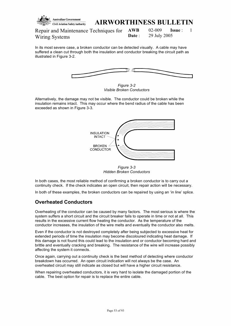
In its most severe case, a broken conductor can be detected visually. A cable may have suffered a clean cut through both the insulation and conductor breaking the circuit path as illustrated in Figure 3-2.
Figure 3-2 Visible Broken Conductors
Alternatively, the damage may not be visible. The conductor could be broken while the insulation remains intact. This may occur where the bend radius of the cable has been exceeded as shown in Figure 3-3.
Figure 3-3 Hidden Broken Conductors
In both cases, the most reliable method of confirming a broken conductor is to carry out a continuity check. If the check indicates an open circuit, then repair action will be necessary.
In both of these examples, the broken conductors can be repaired by using an ‘in line’ splice.
Overheated Conductors
Overheating of the conductor can be caused by many factors. The most serious is where the system suffers a short circuit and the circuit breaker fails to operate in time or not at all. This results in the excessive current flow heating the conductor. As the temperature of the conductor increases, the insulation of the wire melts and eventually the conductor also melts.
Even if the conductor is not destroyed completely after being subjected to excessive heat for extended periods of time the insulation may become discoloured indicating heat damage. If this damage is not found this could lead to the insulation and or conductor becoming hard and brittle and eventually cracking and breaking. The resistance of the wire will increase possibly affecting the system it connects.
Once again, carrying out a continuity check is the best method of detecting where conductor breakdown has occurred. An open circuit indication will not always be the case. An overheated circuit may still indicate as closed but will have a higher circuit resistance.
When repairing overheated conductors, it is very hard to isolate the damaged portion of the cable. The best option for repair is to replace the entire cable.

AIRWORTHINESS BULLETIN AWB 02-009 Issue : 1 Repair and Maintenance Techniques for
Wiring Systems Date : 29 July 2005
Page 54 of 93
Chafed Conductors
Chafing is the result of a cable or harness continually rubbing against another part of the aircraft. It is usually caused by the incorrect routing of the cable or harness, or insufficient support along its entire length.
Chafing causes the insulation of the cable to be worn away and if not detected early, could lead to eventual breaking and shorting/arcing of the conductor as shown in Figure 3-4.
Figure 3-4 Chafed Conductors
Chafing can be repaired by using an in line splice, however, if the damage is along the entire length of the wire a jumper lead will be required to bridge the gap. Ensure the loom has sufficient clearance from the cause of the chaffing. If it is not possible to gain the clearance required then the loom should be wrapped with abrasion resistant material such as Teflon sheet to provide additional protection.
AIRWORTHINESS BULLETIN AWB 02-009 Issue : 1 Repair and Maintenance Techniques for
Wiring Systems Date : 29 July 2005
Page 55 of 93
Chafing can also occur due to differences in hardness of insulation material between adjacent wires. Therefore if a new wire is added to an existing loom it should have the same abrasion characteristics as the existing wires. If a wire of different abrasion characteristic has to be used then it should be routed in separate bundles.
Contamination
Whilst all wiring insulations used in aircraft are resistant to fuels and lubricants, continuous exposure with these chemicals will cause deterioration over time. Also if the chemicals are not kept off the looms, the chemicals can migrate to connectors and other wiring components. If contamination occurs, the looms should be cleaned with appropriate cleaning materials.
Ideally looms should be protected from damage/contamination during maintenance being carried out in the immediate vicinity. If metal shavings are found they should be removed from looms, as the shavings could become trapped in the looms and cut through the insulation and cause a short-circuit.
Connector Damage
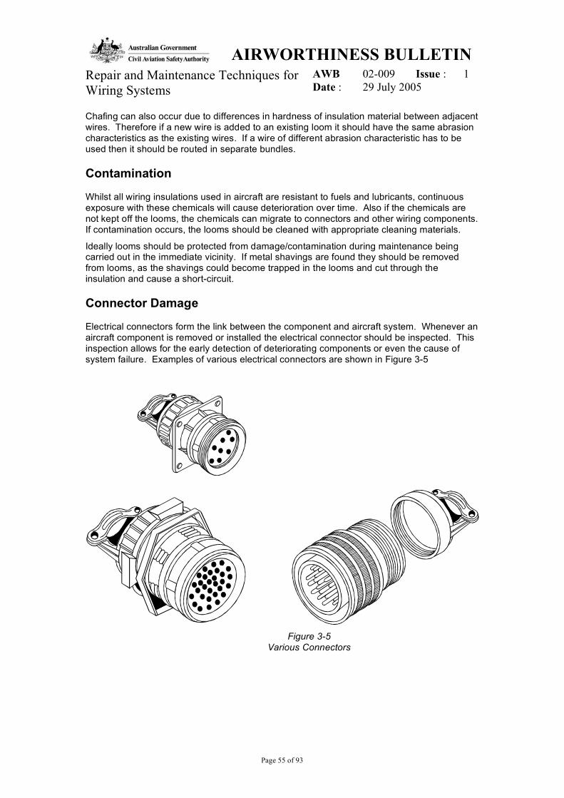
Electrical connectors form the link between the component and aircraft system. Whenever an aircraft component is removed or installed the electrical connector should be inspected. This inspection allows for the early detection of deteriorating components or even the cause of system failure. Examples of various electrical connectors are shown in Figure 3-5
Figure 3-5
Various Connectors

AIRWORTHINESS BULLETIN AWB 02-009 Issue : 1 Repair and Maintenance Techniques for
Wiring Systems Date : 29 July 2005
Page 56 of 93
Whenever disconnecting or reconnecting an electrical connector it must be examined for the following possible damage:
• Pins or sockets pushed back into the insulator;
• Pins bent over or shorting other pins;
• Moisture, corrosion or contamination (this can cause shorts when power is applied);
• The insulator has no cracks or tears and is not perished;
• Wire/s loose in the back of the plug (possible causes are: contact not seated; or wire no longer connected to contact);
• Overall physical condition of the connector; and
• Burn marks caused by poor connections or shorting.
The following precautions should be observed when handling electrical connectors:
Disconnecting electrical connectors
Prior to disconnecting any electrical connector the following precautions are to be observed:
• Ensure system power has been removed (turned off) before disconnecting any of the systems electrical connectors;
• Always use the correct tool to disconnect an electrical connection (soft jawed multigrips called plug pliers);
• Never use the loom to pull a connector from its receptacle;
• When disconnecting a component with multiple plugs, ensure that they are clearly identified to ensure their correct reconnection; and
• Annotate disconnection of electrical connector in appropriate aircraft documentation.
Connecting electrical connectors
Prior to connecting any electrical connector, the following precautions are to be observed:
• Ensure system power has been removed (turned off) before connecting any of the system’s electrical connectors;
• Never force a connector together; always ensure keyways align before attempting connection;
• After connection, ensure that the connector is securely mated (locked in the indent); and
• Ensure that if the connection was previously lock wired the lock wiring is replaced.
Cleaning Technique When contamination is found on wiring and wiring components the manufacturers recommendations should be followed to clean the contaminats off. If there is no manufacturers recommendations following procedure should be applied:
• Apply Isopropyl Alcohol with small brush and scrub affected area to loosen contamination;
• Reapply Isopropyl Alcohol to flush the area;

AIRWORTHINESS BULLETIN AWB 02-009 Issue : 1 Repair and Maintenance Techniques for
Wiring Systems Date : 29 July 2005
Page 57 of 93
• Shake the excess solvent from the wire harness/components and wipe with a clean cloth and allow to air dry; and
• If damage or degradation is found after cleaning, then repair/replace the wire harness, cable covering and wiring components where applicable.
Appropriate Handling Techniques Wiring installations deteriorate through aging and temperature cycling, which is something we have no control over. However, we do have control over other factors such as incorrect or inappropriate maintenance procedures. Minor abuse or apparently insignificant damage will accelerate deterioration of the insulation with time. To minimise degradation, wiring should be handled in accordance with the instructions listed below.
• Individual wires and looms should be handled and moved the minimum amount necessary during a maintenance activity. Minimum bend radii should never be exceeded, especially when wiring is being moved for access.
• Protect looms from contamination due to structural repairs being carried out in the near vicinity.
• Avoid “pulling through” wires during replacement or modifications wherever possible. If unavoidable make sure the wire is not wrapped around the hand for extra grip.
• Piercing of wiring insulation for test purposes should never be performed.
• Ensure there is adequate stain relief for looms particularly where they are located across hinged, movable panels etc.

AIRWORTHINESS BULLETIN AWB 02-009 Issue : 1 Repair and Maintenance Techniques for
Wiring Systems Date : 29 July 2005
Page 58 of 93
Repair Techniques
Techniques employed to repair aircraft wiring vary according to the damage and type of wire requiring repair. A damaged loom may require a combination of the following repair techniques listed below.
• Single Conductor Wire Splicing and Repair.
• Multi-conductor Wire Splicing and Repair.
• Shielded Single and Multi-conductor Wire Splicing and Repair.
• Broken Wire Contact Removal.
• Connector Removal and Installation.
Single Conductor Wire Splicing And Repair
The following text is the repair procedure for a single conductor, non-shielded copper wire of 6 to 26 AWG.
To carry out the repair on a single conductor, a MIL-S-81824 splice is used. The splice is a two piece; environmentally resistant, copper crimp type splice used on 12 to 26 AWG copper wire. They may be used with tin plated and silver plated conductors, where the total temperature of the wire insulation does not exceed 150°C.
Restrictions
The following restrictions apply when carrying out a repair of a single conductor, non-shielded copper wire of 6 to 26 AWG:
Repairs requiring multiple splices must be staggered. Splices should not increase the size of the bundle enough to prevent it from fitting into its designated place or cause congestion that will adversely affect maintenance.
• Splices should not to be used within 300 mm of a termination device except as follows:
When attaching to the pigtail spare lead of a potted termination device;
To splice multiple wires to a single wire; or
To adjust wire sizes so they are compatible with contact crimp barrel sizes.
AIRWORTHINESS BULLETINAWB 02-009 Issue : 1Repair and Maintenance Techniques for
Wiring Systems Date : 29 July 2005
Page 59 of 93
Procedure
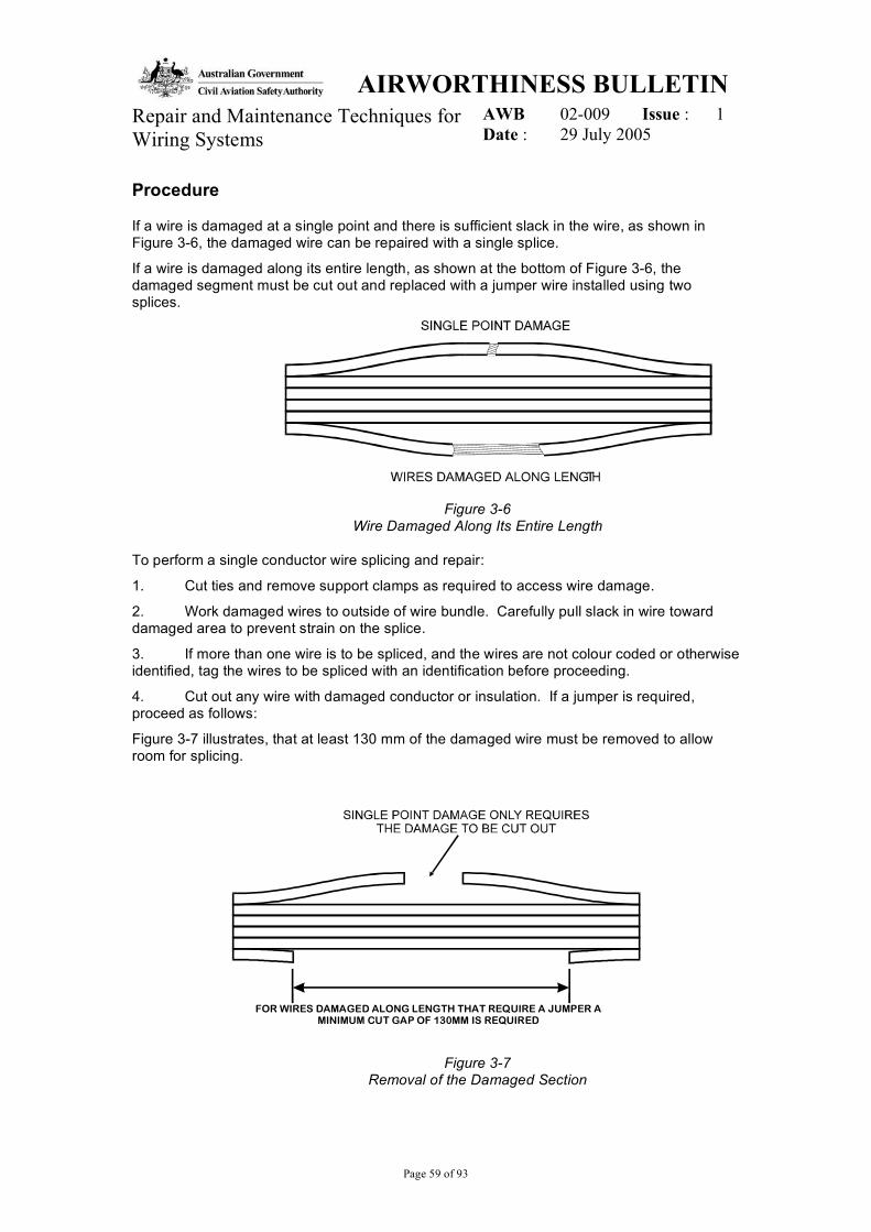
If a wire is damaged at a single point and there is sufficient slack in the wire, as shown inFigure 3-6, the damaged wire can be repaired with a single splice.
If a wire is damaged along its entire length, as shown at the bottom of Figure 3-6, thedamaged segment must be cut out and replaced with a jumper wire installed using twosplices.
Figure 3-6Wire Damaged Along Its Entire Length
To perform a single conductor wire splicing and repair:
1. Cut ties and remove support clamps as required to access wire damage.
2. Work damaged wires to outside of wire bundle. Carefully pull slack in wire towarddamaged area to prevent strain on the splice.
3. If more than one wire is to be spliced, and the wires are not colour coded or otherwiseidentified, tag the wires to be spliced with an identification before proceeding.
4. Cut out any wire with damaged conductor or insulation. If a jumper is required,proceed as follows:
Figure 3-7 illustrates, that at least 130 mm of the damaged wire must be removed to allowroom for splicing.
Figure 3-7Removal of the Damaged Section
FOR WIRES DAMAGED ALONG LENGTH THAT REQUIRE A JUMPER AMINIMUM CUT GAP OF 130MM IS REQUIRED
AIRWORTHINESS BULLETIN AWB 02-009 Issue : 1 Repair and Maintenance Techniques for
Wiring Systems Date : 29 July 2005
Page 60 of 93
• If more than one jumper is to be installed, stagger splice positions by varying lengths of sections that are cut out of damaged wires. This prevents bunching of the splices, keeping the diameter of the loom to a minimum.
• Determine type and gauge of wire being repaired from applicable aircraft wiring data manual.
• Select a jumper wire of the same type and gauge, cutting a 12.5mm longer section than removed.
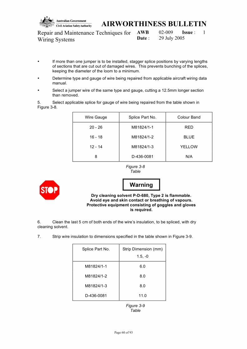
5. Select applicable splice for gauge of wire being repaired from the table shown in Figure 3-8.
Wire Gauge Splice Part No. Colour Band
20 - 26 M81824/1-1 RED
16 - 18 M81824/1-2 BLUE
12 - 14 M81824/1-3 YELLOW
8 D-436-0081 N/A
Figure 3-8 Table
Warning
Dry cleaning solvent P-D-680, Type 2 is flammable. Avoid eye and skin contact or breathing of vapours.
Protective equipment consisting of goggles and gloves is required.
6. Clean the last 5 cm of both ends of the wire’s insulation, to be spliced, with dry cleaning solvent.
7. Strip wire insulation to dimensions specified in the table shown in Figure 3-9.
Splice Part No. Strip Dimension (mm)
1.5, -0
M81824/1-1 6.0
M81824/1-2 8.0
M81824/1-3 8.0
D-436-0081 11.0
Figure 3-9 Table
AIRWORTHINESS BULLETIN AWB 02-009 Issue : 1 Repair and Maintenance Techniques for
Wiring Systems Date : 29 July 2005
Page 61 of 93
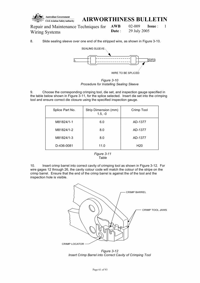
8. Slide sealing sleeve over one end of the stripped wire, as shown in Figure 3-10.
Figure 3-10 Procedure for Installing Sealing Sleeve
9. Choose the corresponding crimping tool, die set, and inspection gauge specified in the table below shown in Figure 3-11, for the splice selected. Insert die set into the crimping tool and ensure correct die closure using the specified inspection gauge.
Splice Part No. Strip Dimension (mm) 1.5, -0
Crimp Tool
M81824/1-1 6.0 AD-1377
M81824/1-2 8.0 AD-1377
M81824/1-3 8.0 AD-1377
D-436-0081 11.0 H20
Figure 3-11 Table
10. Insert crimp barrel into correct cavity of crimping tool as shown in Figure 3-12. For wire gages 12 through 26, the cavity colour code will match the colour of the stripe on the crimp barrel. Ensure that the end of the crimp barrel is against the of the tool and the inspection hole is visible.
Figure 3-12 Insert Crimp Barrel into Correct Cavity of Crimping Tool
AIRWORTHINESS BULLETINAWB 02-009 Issue : 1Repair and Maintenance Techniques for
Wiring Systems Date : 29 July 2005
Page 62 of 93
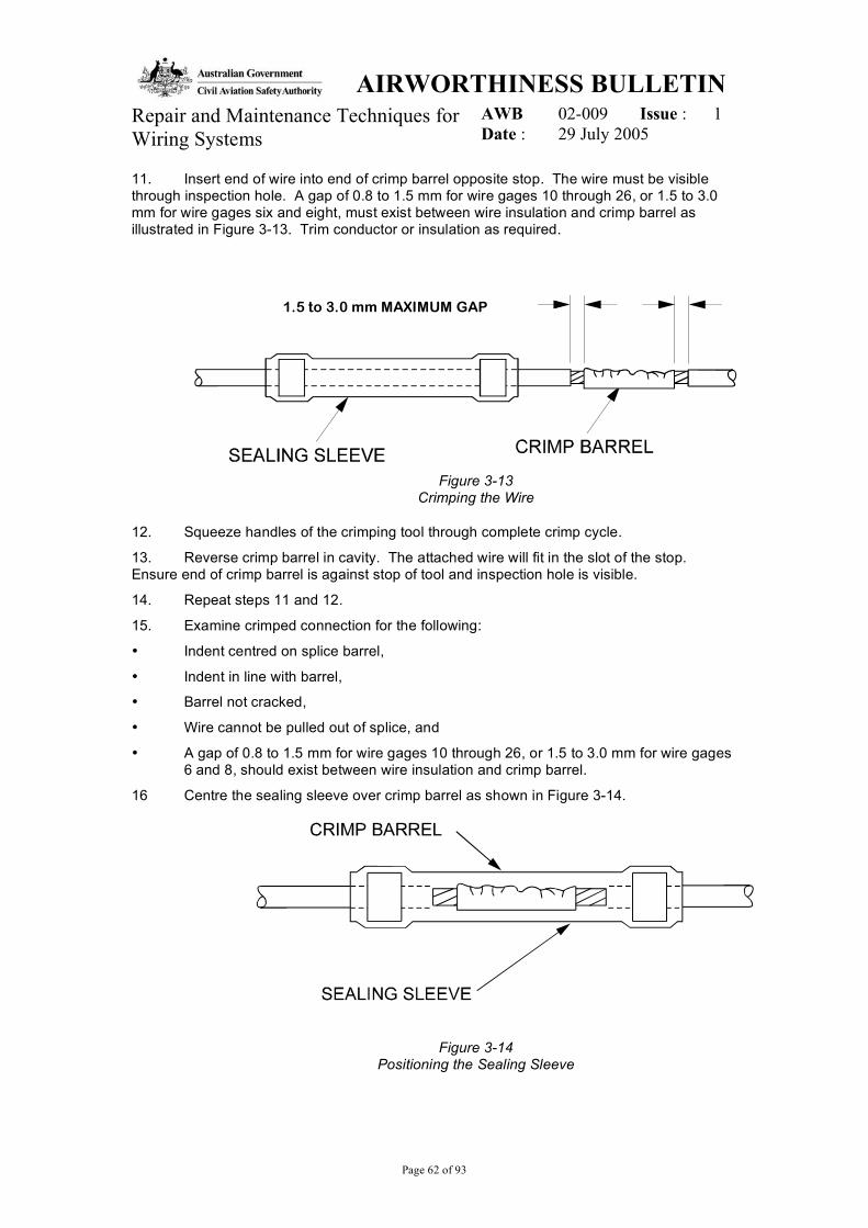
11. Insert end of wire into end of crimp barrel opposite stop. The wire must be visiblethrough inspection hole. A gap of 0.8 to 1.5 mm for wire gages 10 through 26, or 1.5 to 3.0mm for wire gages six and eight, must exist between wire insulation and crimp barrel asillustrated in Figure 3-13. Trim conductor or insulation as required.
Figure 3-13Crimping the Wire
12. Squeeze handles of the crimping tool through complete crimp cycle.
13. Reverse crimp barrel in cavity. The attached wire will fit in the slot of the stop.Ensure end of crimp barrel is against stop of tool and inspection hole is visible.
14. Repeat steps 11 and 12.
15. Examine crimped connection for the following:
¥ Indent centred on splice barrel,
¥ Indent in line with barrel,
¥ Barrel not cracked,
¥ Wire cannot be pulled out of splice, and
¥ A gap of 0.8 to 1.5 mm for wire gages 10 through 26, or 1.5 to 3.0 mm for wire gages6 and 8, should exist between wire insulation and crimp barrel.
16 Centre the sealing sleeve over crimp barrel as shown in Figure 3-14.
Figure 3-14Positioning the Sealing Sleeve
1.5 to 3.0 mm MAXIMUM GAP
AIRWORTHINESS BULLETIN AWB 02-009 Issue : 1 Repair and Maintenance Techniques for
Wiring Systems Date : 29 July 2005
Page 63 of 93
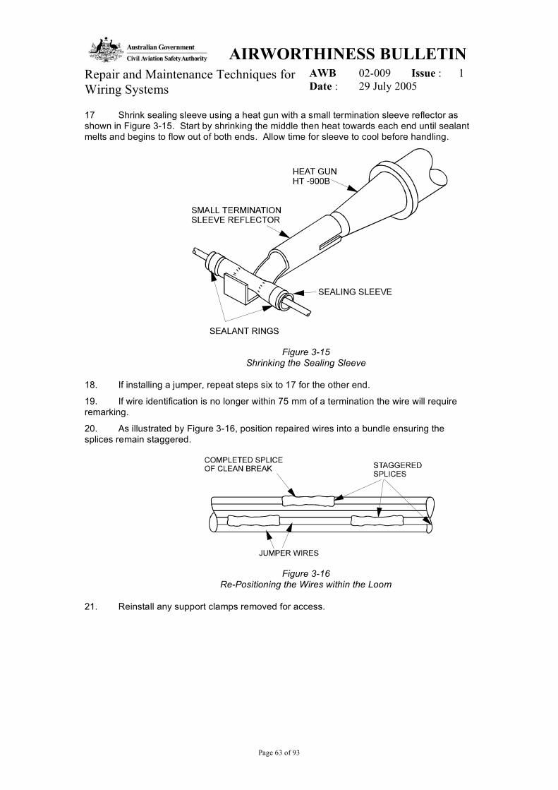
17 Shrink sealing sleeve using a heat gun with a small termination sleeve reflector as shown in Figure 3-15. Start by shrinking the middle then heat towards each end until sealant melts and begins to flow out of both ends. Allow time for sleeve to cool before handling.
Figure 3-15 Shrinking the Sealing Sleeve
18. If installing a jumper, repeat steps six to 17 for the other end.
19. If wire identification is no longer within 75 mm of a termination the wire will require remarking.
20. As illustrated by Figure 3-16, position repaired wires into a bundle ensuring the splices remain staggered.
Figure 3-16 Re-Positioning the Wires within the Loom
21. Reinstall any support clamps removed for access.

AIRWORTHINESS BULLETIN AWB 02-009 Issue : 1 Repair and Maintenance Techniques for
Wiring Systems Date : 29 July 2005
Page 64 of 93
Multi-conductor Wire Splicing And Repair
As with the single conductor wire repair, the MIL-S-81824 splice is also used to repair multi-conductor wire. This means the same restrictions that applied to the single conductor repair will also apply to the multi-conductor repair and the procedures will be similar.
Procedure
1. Cut the ties and remove support clamps, as required, to access the damaged wire.
2. Using a sharp blade or knife, score the cable jacket around the cable and along the length of the damaged area, as shown in Figure 3-17.
Figure 3-17 Removal of Insulation
3. Flex cable at score marks until the jacket separates. Use a sharp blade or knife, if necessary, to complete the cut along the cable.
4. Fold jacket back to gain access to damaged area.
5. If more than one wire is to be spliced and wires are not colour coded, or otherwise identified, tag the wires to be spliced with tape to identify them before proceeding.
6. If a wire is damaged at a single point and there is sufficient slack in the wire, the damaged wire can be repaired with a single splice. If a wire has damage along its length, the damaged segment must be cut out and replaced with a jumper wire installed using two splices.
7. Cut out any segment of damaged wire as illustrated in Figure 3-18.
AIRWORTHINESS BULLETIN AWB 02-009 Issue : 1 Repair and Maintenance Techniques for
Wiring Systems Date : 29 July 2005
Page 65 of 93
Figure 3-18 Removal of Damaged Wire Strands
8. Repeat steps 4 to 20 of the single conductor wire splicing and repair procedure.
9. Fold cable jacket over repaired area ensuring the splices are inside the replaced jacket.
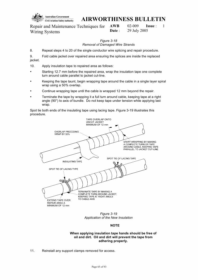
10. Apply insulation tape to repaired area as follows:
• Starting 12.7 mm before the repaired area, wrap the insulation tape one complete turn around cable parallel to jacket cut-line.
• Keeping the tape taunt, begin wrapping tape around the cable in a single layer spiral wrap using a 50% overlap.
• Continue wrapping tape until the cable is wrapped 12 mm beyond the repair.
• Terminate the tape by wrapping it a full turn around cable, keeping tape at a right angle (90°) to axis of bundle. Do not keep tape under tension while applying last wrap.
Spot tie both ends of the insulating tape using lacing tape. Figure 3-19 illustrates this procedure.
Figure 3-19 Application of the New Insulation
NOTE
When applying insulation tape hands should be free of oil and dirt. Oil and dirt will prevent the tape from
adhering properly.
11. Reinstall any support clamps removed for access.
TAPE OVERLAP ONTO UNCUT JACKET MINIMUM OF 12 mm
EXTEND TAPE OVER REPAIR AREA A MINIMUM OF 12 mm
AIRWORTHINESS BULLETIN AWB 02-009 Issue : 1 Repair and Maintenance Techniques for
Wiring Systems Date : 29 July 2005
Page 66 of 93
Shielded Single and Multi-conductor Wire Splicing And Repair
The procedure for repairing shielded single and multi-conductor wire is very similar to the methods so far covered. The main difference is the additional repair work required to remove a section of the shielding, and the work required to replace it after the damaged wire/s are repaired.
Preparation
1. Cut ties and remove clamps as required to gain access to damaged shielded cable.
2. Select a shield repair kit according to outside diameter of damaged cable jacket and as specified in the relevant aircraft publication.
3. Remove the damaged jacket and shield using the following procedure:
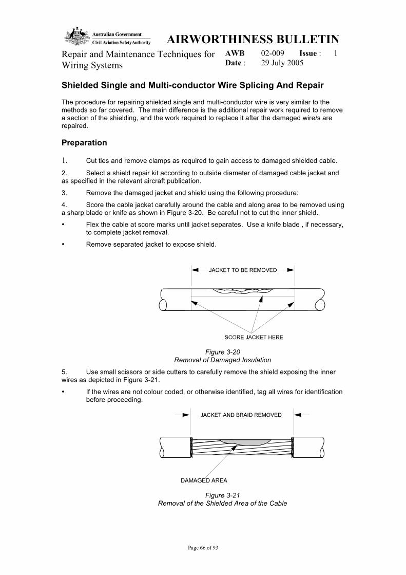
4. Score the cable jacket carefully around the cable and along area to be removed using a sharp blade or knife as shown in Figure 3-20. Be careful not to cut the inner shield.
• Flex the cable at score marks until jacket separates. Use a knife blade , if necessary, to complete jacket removal.
• Remove separated jacket to expose shield.
Figure 3-20 Removal of Damaged Insulation
5. Use small scissors or side cutters to carefully remove the shield exposing the inner wires as depicted in Figure 3-21.
• If the wires are not colour coded, or otherwise identified, tag all wires for identification before proceeding.
Figure 3-21 Removal of the Shielded Area of the Cable

AIRWORTHINESS BULLETINAWB 02-009 Issue : 1Repair and Maintenance Techniques for
Wiring Systems Date : 29 July 2005
Page 67 of 93
Damaged Wire Splicing
The example in the following paragraphs demonstrates the splicing of a shielded multi-conductor wire.
NOTE
The same procedure can be adapted for shielded singlewire.
1. Cut the damaged wire or wires to remove all damaged portions. If the damage is at asingle point, the damaged wire can be cut at the point of the damage. If the damaged wiremust be cut out, then remove at least 50 mm of the total length as illustrated in Figure 3-22.
Figure 3-22Damaged Wire Splicing
2. Cut the remaining undamaged wires at staggered locations as shown in Figure 3-23.Cutting the undamaged wires is necessary to install the braid, solder sleeves and tubing,required for the repair over the cable ends. The repair components are installed in this wayas it is rarely possible to slide them on from either end of the cable.
Figure 3-23Cutting the Remaining Undamaged Wires at Staggered
Locations
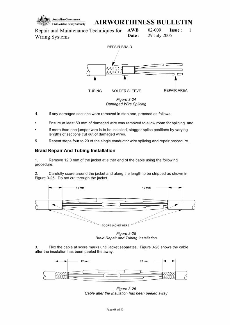
3. Slide tubing, solder sleeves and braid from shield repair kit over either cable end.Figure 3-24 shows the repair components on the left-hand side of the cable. The otherrequired solder sleeve would be slid over the right-hand cable end.
50 mm MINIMUMDAMAGED LENGTHREMOVED
AIRWORTHINESS BULLETINAWB 02-009 Issue : 1Repair and Maintenance Techniques for
Wiring Systems Date : 29 July 2005
Page 68 of 93
Figure 3-24Damaged Wire Splicing
4. If any damaged sections were removed in step one, proceed as follows:
¥ Ensure at least 50 mm of damaged wire was removed to allow room for splicing. and
¥ If more than one jumper wire is to be installed, stagger splice positions by varyinglengths of sections cut out of damaged wires.
5. Repeat steps four to 20 of the single conductor wire splicing and repair procedure.
Braid Repair And Tubing Installation
1. Remove 12.0 mm of the jacket at either end of the cable using the followingprocedure:
2. Carefully score around the jacket and along the length to be stripped as shown inFigure 3-25. Do not cut through the jacket.
Figure 3-25Braid Repair and Tubing Installation
3. Flex the cable at score marks until jacket separates. Figure 3-26 shows the cableafter the insulation has been peeled the away.
Figure 3-26Cable after the Insulation has been peeled away
12 mm 12 mm
12 mm 12 mm
AIRWORTHINESS BULLETIN AWB 02-009 Issue : 1 Repair and Maintenance Techniques for
Wiring Systems Date : 29 July 2005
Page 69 of 93
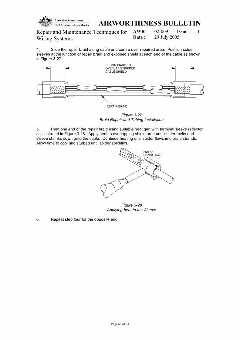
4. Slide the repair braid along cable and centre over repaired area. Position solder sleeves at the junction of repair braid and exposed shield at each end of the cable as shown in Figure 3-27.
Figure 3-27 Braid Repair and Tubing Installation
5. Heat one end of the repair braid using suitable heat gun with terminal sleeve reflector as illustrated in Figure 3-28. Apply heat to overlapping shield area until solder melts and sleeve shrinks down onto the cable. Continue heating until solder flows into braid strands. Allow time to cool undisturbed until solder solidifies.
Figure 3-28 Applying heat to the Sleeve
6. Repeat step four for the opposite end.
AIRWORTHINESS BULLETIN AWB 02-009 Issue : 1 Repair and Maintenance Techniques for
Wiring Systems Date : 29 July 2005
Page 70 of 93
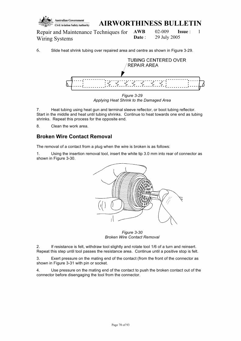
6. Slide heat shrink tubing over repaired area and centre as shown in Figure 3-29.
Figure 3-29
Applying Heat Shrink to the Damaged Area
7. Heat tubing using heat gun and terminal sleeve reflector, or boot tubing reflector. Start in the middle and heat until tubing shrinks. Continue to heat towards one end as tubing shrinks. Repeat this process for the opposite end.
8. Clean the work area.
Broken Wire Contact Removal
The removal of a contact from a plug when the wire is broken is as follows:
1. Using the insertion removal tool, insert the white tip 3.0 mm into rear of connector as shown in Figure 3-30.
Figure 3-30 Broken Wire Contact Removal
2. If resistance is felt, withdraw tool slightly and rotate tool 1/6 of a turn and reinsert. Repeat this step until tool passes the resistance area. Continue until a positive stop is felt.
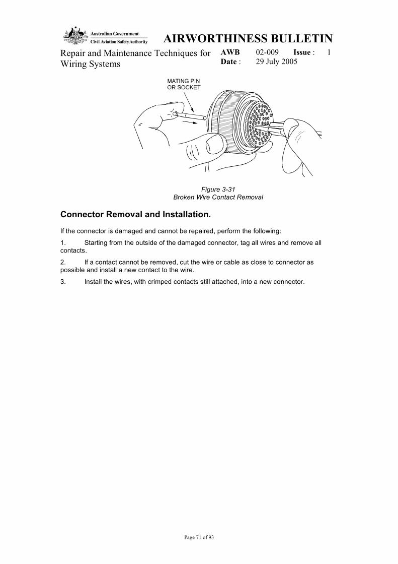
3. Exert pressure on the mating end of the contact (from the front of the connector as shown in Figure 3-31 with pin or socket.
4. Use pressure on the mating end of the contact to push the broken contact out of the connector before disengaging the tool from the connector.
AIRWORTHINESS BULLETIN AWB 02-009 Issue : 1 Repair and Maintenance Techniques for
Wiring Systems Date : 29 July 2005
Page 71 of 93
Figure 3-31 Broken Wire Contact Removal
Connector Removal and Installation.
If the connector is damaged and cannot be repaired, perform the following:
1. Starting from the outside of the damaged connector, tag all wires and remove all contacts.
2. If a contact cannot be removed, cut the wire or cable as close to connector as possible and install a new contact to the wire.
3. Install the wires, with crimped contacts still attached, into a new connector.

AIRWORTHINESS BULLETIN AWB 02-009 Issue : 1 Repair and Maintenance Techniques for
Wiring Systems Date : 29 July 2005
Page 72 of 93
Page Intentionally Left Blank


![Untitled-1 [] · 2018. 12. 15. · Memcom Wiring Looms Product Information Sheet TheMemcom wiring looms have been developed to allow the quick and simple integration of aMemcom unit](https://img.pdfslide.net/doc/110x75/613bd04ff8f21c0c826935d5/untitled-1-2018-12-15-memcom-wiring-looms-product-information-sheet-thememcom.jpg)