Embed Size (px)
Citation preview
SECTION
1. GENERAL INFORMATION
2. INTRODUCTION PRODUCT OPERATING MANUAL
3. PREPARATION FOR OPERATION Manual No. ZVP-PC-0061-01
4. OPERATING INSTRUCTIONS AIRFLO PNEUMATIC REMOTE CONTROL HANDLE 5. MAINTENANCE 6. TROUBLE SHOOTING GUIDE 7. ASSEMBLIES, PARTS LISTING & EXPLODED VIEW Panblast Pte Ltd 2 Woodlands Sector 1 #05-20 Woodlands Spectrum I Singapore 738068 Tel: 65-6586-1583 Fax: 65-6586-1563 Email: [email protected] Website: www.panblast.com An ISO9001:2008 Quality Management System Certified Company
PRODUCT OPERATING MANUAL
- 1 -
1.0 GENERAL INFORMATION 1.1 All products and equipment designed and
manufactured by Pan Abrasives are intended for use by experienced users of abrasive blasting equipment and its associated operations and abrasive blasting media.
1.2 It is the responsibility of the user to:
1.2.1 Determine if the equipment and abrasive media is suitable for the users' intended use and application.
1.2.2 Familiarize themselves with any
appropriate laws, regulations and safe working practices which may apply within the users' working environment.
1.2.3 Provide appropriate operator training
and a safe working environment including operator protective equipment such as, but not limited to, blasting suit, safety footwear, protective eyewear and hearing protection.
1.3 Pan Abrasives Standard Terms and Conditions
of Sale apply. Contact your local Pan Abrasives office or distributor should you require any further information or assistance.
! WARNING ! – READ THIS SECTION
CAREFULLY BEFORE USING THIS EQUIPMENT.
1.4 Heavy metal paint, asbestos and other toxic material dusts will cause serious lung disease or death without the use of properly designed and approved air supplied respiratory equipment by blast operators and all personnel within the work site area.
1.5 The compressor must have adequate output
and the plumbing between the compressor and the point of attaching the air supply hose must have sufficient capacity to supply the volume of air at the pressure required
1.6 Standard Safety Precautions 1.7 Approved safety eyewear, hearing and footwear
protection should be worn at all times by the operator and anyone else in the immediate area that may be exposed to any hazards generated by the abrasive blasting process.
1.8 Suitably approved respiratory protection should
also be worn when handling abrasive media, abrasive refuse dust and when carrying out any service/maintenance work where any dust may be present.
1.9 Any work performed on electrical wiring or
components must only be carried out by suitably qualified and registered electrical trades’ personnel.
1.10 Under no circumstances should any safety
interlocks or features be altered or disabled in
any way. 1.11 All equipment must be isolated from the
compressed air supply and electrical power source prior to any service or maintenance work being carried out.
1.12 All care must be taken by the operator when
lifting or moving equipment or components in order to prevent injury. Pressure Blast Pots must always be emptied of abrasive media before any attempt is made to move them.
1.13 Any modification of the equipment or use of
non genuine PanBlast™ replacement parts will void warranty.
1.14 Always check the Material Safety Data Sheet on
the abrasive being used to ensure that it is free of harmful substances, in particular, free silica, cyanide, arsenic or lead.
1.15 Test the surface to be blasted for harmful
substances, taking the appropriate measures and precautions to ensure the safety of the operator and others.
1.16 The operator should carry out a daily inspection
before start up of all wearing and safety items to ensure that they are in correct operating order. In particular check all blast hose couplings and nozzle holders, ensuring that all couplings have engaged correctly and the Safety Locking Pins are fitted and in good condition. Always install safety whip check cables at every connection. Ensure that the blast nozzle has been securely screwed into the nozzle holder and the nozzle holder has been secured to the blast hose correctly and that all screws are engaged.
2.0 INTRODUCTION 2.1 These instructions cover the installation,
operation and maintenance of the PanBlast™ AirFlo Pneumatic Remote Control Handle series in pneumatic configurations.
2.2 The PanBlast™ AirFlo Pneumatic Remote Control
Handle is an air “bleed off” style deadman handle used for the remote control of abrasive blast pots. When operated it supplies a pneumatic signal to the blast pot remote control system which then activates the blasting process.
2.3 It can be used with the PanBlast™ range of
remote control valve systems such as the UniFlo, Helix, Sola, Kombi, Tandem and Pinch Valve System.
NOTE: UNDER OSHA 1915:34(c )(1 ) ( iv ) DEADMAN CONTROL. A DEADMAN CONTROL DEVICE SHALL BE PROVIDED AT THE NOZZLE
PRODUCT OPERATING MANUAL
- 2 -
END OF THE BLAST HOSE EITHER TO PROVIDE DIRECT CUTOFF OR TO SIGNAL THE POT TENDER BY MEANS OF A VISUAL AND AUDIBLE SIGNAL TO CUT OFF THE FLOW, IN THE EVENT THE BLASTER LOSES CONTROL OF THE HOSE. THE POT TENDER SHALL BE AVAILABLE AT ALL TIMES TO RESPOND IMMEDIATELY TO THE SIGNAL.
3.0 PREPARATION FOR OPERATION 3.1 Attach the AirFlo deadman control handle to
the blast hose behind the nozzle holder using robust bands or strapping. Trim any excess after fixing the handle so that they don't catch or interfere with the operator during blasting.
3.2 Connect the Twinline Hose fittings ensuring
that the supply line is connected to the inlet port and the return signal line is connected to the outlet port.
! WARNING ! – INCORRECT CONNECTION
OF THE TWINLINE HOSE FITTINGS TO THE REMOTE CONTROL HANDLE OR REMOTE CONTROL VALVE MAY CAUSE PREMATURE PRESSURIZATION OF THE SYSTEM RESULTING IN SERIOUS INJURY OR DEATH.
3.3 The Twinline Hose should be strapped to the Blast Hose at 1 metre intervals.
3.4 Connect the two end fittings to the control
valve via the Quick Disconnect Fitting supplied with the Twinline Hose assembly and those supplied on the Remote Control Valve.
4.0 OPERATING INSTRUCTIONS
! WARNING ! – READ THIS SECTION CAREFULLY BEFORE USING THIS EQUIPMENT/ APPARATUS.
4.1 PanBlast™ AirFlo deadman control handle is a “bleed off” style deadman handle. When the handle is in the "Up" or un-activated position the air supply from the blast pot supply is bled off to atmosphere via an orifice in the handle manifold. When the handle is "Down" or in the activated position the orifice is closed off and a return signal is supplied to the blast pot remote control system activating the blast pot and initializing the blast process.
4.2 Before pressurizing the system check the
operation of the handle, is the deadman latch operational? Does it snap back to the “Up” position on releasing of the lever handle? Does the lever handle spring back when released? Ensure it is free in its action.
4.3 Connect the blast pot to an air supply that is adequate for the application, check the nozzle air requirement and the minimum air pressure required to operate the remote control valve.
4.4 Ensure that the mini ball valve or pet cock on
the remote control valve has been closed. 4.5 Check that the air is escaping from the bleed
orifice on the handle manifold when the main air supply valve is opened.
4.6 After following all start up procedures as
detailed in the abrasive blast pot manual, pull back the safety lever lock, hold this lever down and depress the lever handle. This will close off the air bleeding from the manifold and initiate the blasting process. Blasting will begin within a few seconds.
4.7 To stop blasting, release the lever handle, the
safety lever lock will snap up preventing the lever handle from being depressed and air will again bleed off from the handle manifold. Blasting will cease within 2-3 seconds.
! WARNING ! – THE LEVER MUST NEVER BE
WIRED OR BANDED DOWN PERMANENTLY WHICH MAY RESULT IN PREMATURE ACTIVATION OF THE SYSTEM THAT MAY CAUSE SERIOUS INJURY OR DEATH.
5.0 MAINTENANCE 5.1 Check the operation of the safety lever lock and
lever handle on a regular basis. 5.2 Replace any broken or faulty components
immediately. 5.3 Check the condition of the bumper button on
the underside of the lever handle, and replace the bumper button if it no longer seals off the bleed hole.
5.4 Periodically check that the restricted hole in the
inlet fitting to the handle is clear and has not reduced in size due to dust and moisture build up.
5.5 Ensure that the handle strapping is in good
order, replace as required.
PRODUCT OPERATING MANUAL
- 3 -
6.0 TROUBLE SHOOTING GUIDE
PROBLEM PROBABLE SOLUTION
Ensure that the “Safety” mini ball valve or pet cock on the Remote Control Valve has been closed.
Check that the air is escaping from the bleed off hole in the handle manifold with the handle in the "Up" position. If not, check for air leaks in the supply line to the handle and check the inlet fitting to ensure that it is not blocked.
The lever is depressed but the
Remote Control Valve does not
activate.
Check that the bumper button is sealing on the manifold orifice, there should be no air leakage from the orifice when the handle is depressed.
Check that the handle lever spring has not been damaged and is free in its action. Replace if required. The Lever does
not pop up when released. Check that the handle lever pin is
not jammed due to intrusion of abrasive dust.
The “Safety Lock-Out” button does not spring back to the “Safety Lock-
Out” position.
Check that the “Safety Lock-Out” button has not seized in the Remote Control Handle body housing, or has not been damaged it should always be free in its action and not jammed due to abrasives dust
Check that the Twinline is connected correctly, i.e.: the “live” supply line is connected to the correct inlet port and the signal line to the correct outlet port.
Check that the plunger is free in its movement and ensure that the bleed hole is free and clear of any obstruction.
The system starts up as soon as air
is turned on without the Lever handle depressed.
Refer to the Pressure Blast Machine Remote Control Valve for correct and functional operation.
PRODUCT OPERATING MANUAL
- 4 -
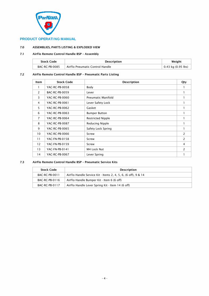
7.0 ASSEMBLIES, PARTS LISTING & EXPLODED VIEW 7.1 AirFlo Remote Control Handle BSP – Assembly
Stock Code Description Weight
BAC-RC-PB-0085 AirFlo Pneumatic Control Handle 0.43 kg (0.95 lbs)
7.2 AirFlo Remote Control Handle BSP – Pneumatic Parts Listing
Item Stock Code Description Qty
1 YAC-RC-PB-0058 Body 1
2 BAC-RC-PB-0059 Lever 1
3 YAC-RC-PB-0060 Pneumatic Manifold 1
4 YAC-RC-PB-0061 Lever Safety Lock 1
5 YAC-RC-PB-0062 Gasket 1
6 YAC-RC-PB-0063 Bumper Button 1
7 YAC-RC-PB-0064 Restricted Nipple 1
8 YAC-RC-PB-0087 Reducing Nipple 1
9 YAC-RC-PB-0065 Safety Lock Spring 1
10 YAC-RC-PB-0066 Screw 2
11 YAC-FN-PB-0158 Screw 2
12 YAC-FN-PB-0159 Screw 4
13 YAC-FN-PB-0141 M4 Lock Nut 2
14 YAC-RC-PB-0067 Lever Spring 1
7.3 AirFlo Remote Control Handle BSP – Pneumatic Service Kits
Stock Code Description
BAC-RC-PB-0011 AirFlo Handle Service Kit - Items 2, 4, 5, 6, (6 off), 9 & 14
BAC-RC-PB-0116 AirFlo Handle Bumper Kit - Item 6 (6 off)
BAC-RC-PB-0117 AirFlo Handle Lever Spring Kit - Item 14 (6 off)

PRODUCT OPERATING MANUAL
- 5 -
7.4 Product Exploded View - AirFlo Remote Control Handle BSP - Pneumatic
PRODUCT OPERATING MANUAL
- 6 -
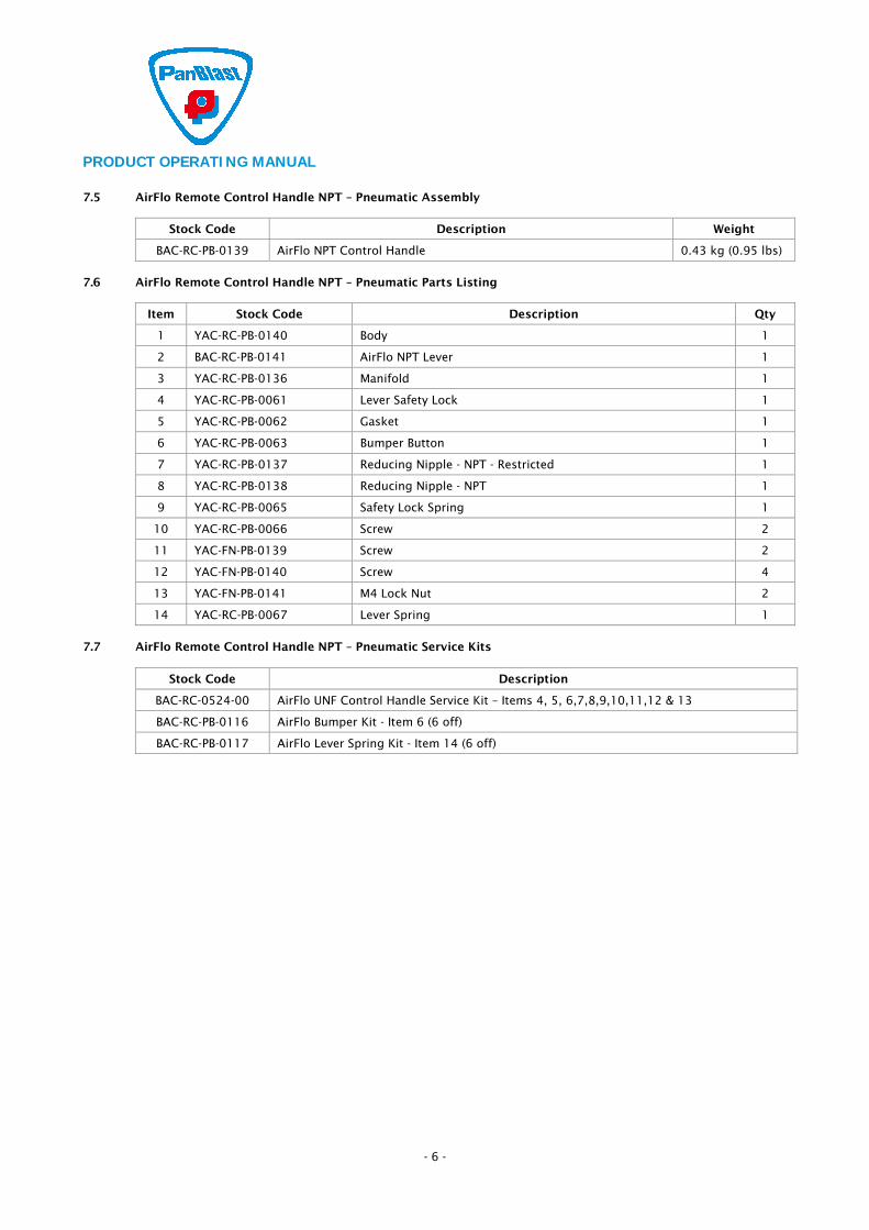
7.5 AirFlo Remote Control Handle NPT – Pneumatic Assembly
Stock Code Description Weight
BAC-RC-PB-0139 AirFlo NPT Control Handle 0.43 kg (0.95 lbs)
7.6 AirFlo Remote Control Handle NPT – Pneumatic Parts Listing
Item Stock Code Description Qty
1 YAC-RC-PB-0140 Body 1
2 BAC-RC-PB-0141 AirFlo NPT Lever 1
3 YAC-RC-PB-0136 Manifold 1
4 YAC-RC-PB-0061 Lever Safety Lock 1
5 YAC-RC-PB-0062 Gasket 1
6 YAC-RC-PB-0063 Bumper Button 1
7 YAC-RC-PB-0137 Reducing Nipple - NPT - Restricted 1
8 YAC-RC-PB-0138 Reducing Nipple - NPT 1
9 YAC-RC-PB-0065 Safety Lock Spring 1
10 YAC-RC-PB-0066 Screw 2
11 YAC-FN-PB-0139 Screw 2
12 YAC-FN-PB-0140 Screw 4
13 YAC-FN-PB-0141 M4 Lock Nut 2
14 YAC-RC-PB-0067 Lever Spring 1
7.7 AirFlo Remote Control Handle NPT – Pneumatic Service Kits
Stock Code Description
BAC-RC-0524-00 AirFlo UNF Control Handle Service Kit – Items 4, 5, 6,7,8,9,10,11,12 & 13
BAC-RC-PB-0116 AirFlo Bumper Kit - Item 6 (6 off)
BAC-RC-PB-0117 AirFlo Lever Spring Kit - Item 14 (6 off)

PRODUCT OPERATING MANUAL
- 7 -
7.8 Product Exploded View - AirFlo Remote Control Handle NPT - Pneumatic
PRODUCT OPERATING MANUAL
- 8 -
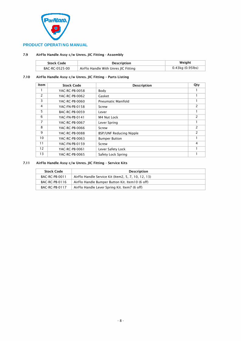
7.9 AirFlo Handle Assy c/w Unres. JIC Fitting - Assembly
Stock Code Description Weight
BAC-RC-0525-00 AirFlo Handle With Unres JIC Fitting 0.43kg (0.95lbs)
7.10 AirFlo Handle Assy c/w Unres. JIC Fitting – Parts Listing
Item Stock Code Description Qty
1 YAC-RC-PB-0058 Body 1
2 YAC-RC-PB-0062 Gasket 1
3 YAC-RC-PB-0060 Pneumatic Manifold 1
4 YAC-FN-PB-0158 Screw 2
5 BAC-RC-PB-0059 Lever 1
6 YAC-FN-PB-0141 M4 Nut Lock 2
7 YAC-RC-PB-0067 Lever Spring 1
8 YAC-RC-PB-0066 Screw 2
9 YAC-RC-PB-0088 BSP/UNF Reducing Nipple 2
10 YAC-RC-PB-0063 Bumper Button 1
11 YAC-FN-PB-0159 Screw 4
12 YAC-RC-PB-0061 Lever Safety Lock 1
13 YAC-RC-PB-0065 Safety Lock Spring 1
7.11 AirFlo Handle Assy c/w Unres. JIC Fitting – Service Kits
Stock Code Description
BAC-RC-PB-0011 AirFlo Handle Service Kit (Item2, 5, 7, 10, 12, 13)
BAC-RC-PB-0116 AirFlo Handle Bumper Button Kit. Item10 (6 off)
BAC-RC-PB-0117 AirFlo Handle Lever Spring Kit. Item7 (6 off)

PRODUCT OPERATING MANUAL
- 9 -
7.12 Product Exploded View - AirFlo Handle Assy c/w Unres. JIC Fitting
PRODUCT OPERATING MANUAL
- 10 -
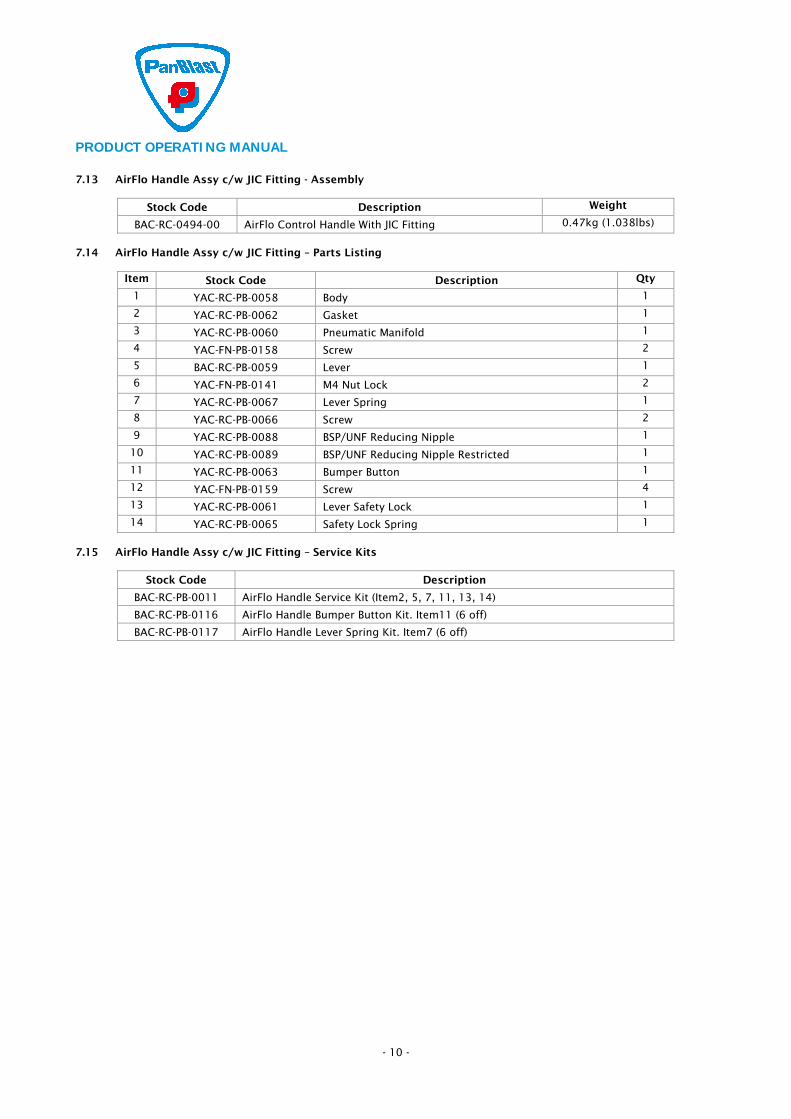
7.13 AirFlo Handle Assy c/w JIC Fitting - Assembly
Stock Code Description Weight
BAC-RC-0494-00 AirFlo Control Handle With JIC Fitting 0.47kg (1.038lbs)
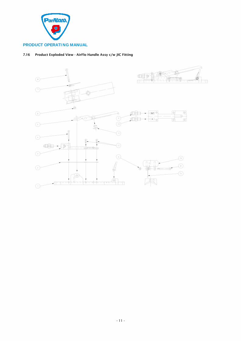
7.14 AirFlo Handle Assy c/w JIC Fitting – Parts Listing
Item Stock Code Description Qty
1 YAC-RC-PB-0058 Body 1
2 YAC-RC-PB-0062 Gasket 1
3 YAC-RC-PB-0060 Pneumatic Manifold 1
4 YAC-FN-PB-0158 Screw 2
5 BAC-RC-PB-0059 Lever 1
6 YAC-FN-PB-0141 M4 Nut Lock 2
7 YAC-RC-PB-0067 Lever Spring 1
8 YAC-RC-PB-0066 Screw 2
9 YAC-RC-PB-0088 BSP/UNF Reducing Nipple 1
10 YAC-RC-PB-0089 BSP/UNF Reducing Nipple Restricted 1
11 YAC-RC-PB-0063 Bumper Button 1
12 YAC-FN-PB-0159 Screw 4
13 YAC-RC-PB-0061 Lever Safety Lock 1
14 YAC-RC-PB-0065 Safety Lock Spring 1
7.15 AirFlo Handle Assy c/w JIC Fitting – Service Kits
Stock Code Description
BAC-RC-PB-0011 AirFlo Handle Service Kit (Item2, 5, 7, 11, 13, 14)
BAC-RC-PB-0116 AirFlo Handle Bumper Button Kit. Item11 (6 off)
BAC-RC-PB-0117 AirFlo Handle Lever Spring Kit. Item7 (6 off)
PRODUCT OPERATING MANUAL
- 11 -
7.16 Product Exploded View - AirFlo Handle Assy c/w JIC Fitting


![3536/01-230.2 GB AirFlo-Lite - Keison Products · 2 AirFlo-Lite with Cavair Hood LDA [Cavair Hood LDA] A classic paint spray hoodwith some novel advantages. The elasticated face seal](https://img.pdfslide.net/doc/110x75/6023e909fb145716382f60cd/353601-2302-gb-airflo-lite-keison-2-airflo-lite-with-cavair-hood-lda-cavair.jpg)