Embed Size (px)
Citation preview

We reserve the right to modify technical specif ications without prior notice.83053500dUK – Translation of the operating manual © Alpha-InnoTec GmbH
Heat PumPs
Operat ing manual
Dual / Outdoor Installation
aIr/Water
uK
LWD 50a • LWD 70a • LWD 90aLWD 50a/rX • LWD 70a/rX

2We reserve the right to modify technical specif ications without prior notice.83053500dUK – Translation of the operating manual © Alpha-InnoTec GmbH
Please read firstThis operating manual provides important information on the handling of the unit. It is an integral part of the product and must be stored so that it is accessible in the immediate vicinity of the unit. It must remain available throughout the entire service life of the unit. It must be handed over to subsequent owners or users of the unit.
Read the operating manual before working on or operating the unit. This applies in particular to the chapter on safety. Always follow all instructions completely and without restrictions.
It is possible that this operating manual may contain instructions that seem incomprehensible or unclear. In the event of any questions or if any details are unclear, contact the factory customer service department or the manufacturer’s local partner.
Since this operating manual was written for several different models of the unit, always comply with the parameters for the respective model.
This operating manual is intended only for persons assigned to work on or operate the unit. Treat all constituent parts confidentially. The information contained herein is protected by copyright. No part of this manual may be reproduced, transmitted, copied, stored in electronic data systems or translated into another language, either wholly or in part, without the express written permission of the manufacturer.
symbolsThe following symbols are used in the operating manual. They have the following meaning:
Information for operators.
Information or instructions for qualified technicians.
Danger! Indicates a direct impending danger
resulting in severe injuries or death.
WarnIng! Indicates a potentially dangerous situation
that could result in serious injuries or death.
CautIon! Indicates a potentially dangerous situation
that could result in medium or slight injuries.
attentIon Indicates a potentially dangerous situation, which
could result in property damage.
notICe. Emphasised information.
Flammable materials
Dangerous electrical voltage
€ energy savIng tIp Indicates suggestions that help to save energy,
raw materials and costs.
Reference to other sections of the operating manual.
Reference to other documents of the manufacturer.

3
Contents
INfoRmATIoN foR USERS ANd qUAlIfIEd pERSoNNEl
plEASE REAd fIRST ..................................................................2
SymbolS .....................................................................................2
INTENdEd USE ..........................................................................4
dISclAImER................................................................................4
Ec coNfoRmITy .....................................................................4
SAfETy .........................................................................................4
cUSTomER SERvIcE ................................................................5
WARRANTy / GUARANTEE ....................................................5
dISpoSAl ....................................................................................5
opERATING pRINcIplE of HEAT pUmpS ..........................6
AREA of UTIlISATIoN ............................................................6
HEAT mETERING .......................................................................6
opERATIoN ................................................................................6
cARE of THE UNIT ..................................................................6
mAINTENANcE of THE UNIT ..............................................6cleaning and flushing of unit components ........................7
mAlfUNcTIoNS .......................................................................7
INSTRUcTIoNS foR qUAlIfIEd TEcHNIcIANS
ScopE of dElIvERy ..................................................8
INSTAllATIoN ANd ASSEmbly ...........................................8Installation location ..............................................................8Transport to installation location ......................................9Installation ..............................................................................9Installation with wall bracket ............................................10INSTAllATIoN oN flooR bRAcKET .......................10condensate drain ..............................................................10connection to the heating circuit .................................... 11Electrical connections ........................................................12
pRESSURE RElIEf .....................................................................12
ovERfloW vAlvE ..................................................................12
bUffER TANK...........................................................................12
cIRcUlATING pUmpS ...........................................................12
domESTIc WATER HEATING ..............................................12
domESTIc HoT WATER TANK ..........................................13
RINSING, fIllING ANd blEEdING THE SySTEm ..........13Water quality of the fill and additional water in hot
water heating systems .................................................13
INSUlATING THE HydRAUlIc coNNEcTIoNS ..........15
commISSIoNING ...................................................................15
dISmANTlING .........................................................................16Withdrawal from service ...................................................16markings ...............................................................................16Recovery/recycling .............................................................. 17
TEcHNIcAl dATA / ScopE of dElIvERylWd 50A – lWd 90A .......................................................18
TEcHNIcAl dATA / ScopE of dElIvERylWd 50A /RX– lWd 70A/RX .........................................20
pERfoRmANcE cURvESlWd 50A..............................................................................22lWd 70A ..............................................................................23lWd 90A ............................................................................24lWd 50A/RX Heating mode ............................................25lWd 50A/RX cooling mode ............................................26lWd 70A/RX Heating mode ............................................27lWd 70A/RX cooling mode ............................................28
SoUNd pRESSURE lEvEl ......................................................29
dImENSIoNAl dRAWINGS .................................................30
INSTAllATIoN pRoTEcTIoN AREAS ...............................31
WAll bRAcKET INSTAllATIoN plAN ...........................32flooR bRAcKET INSTAllATIoN plAN ..........................33
dRIllING pATTERN foR WAll bRAcKET .....................36
vIEW of foUNdATIoN .......................................................38mINImUm clEARANcES ...................................................... 40
oUTSIdE coNNEcTIoN of coNdENSATE pIpE .........41
cIRcUIT dIAGRAmSlWd 50A(RX) – lWd 70A(RX), lWd 90A ..................43
AppENdIX
Ec dEclARATIoN of coNfoRmITy ..............................45
cUSTomER SERvIcE
Addresses for service .........................................................46
We reserve the right to modify technical specif ications without prior notice.83053500dUK – Translation of the operating manual © Alpha-InnoTec GmbH
4We reserve the right to modify technical specif ications without prior notice.83053500dUK – Translation of the operating manual © Alpha-InnoTec GmbH
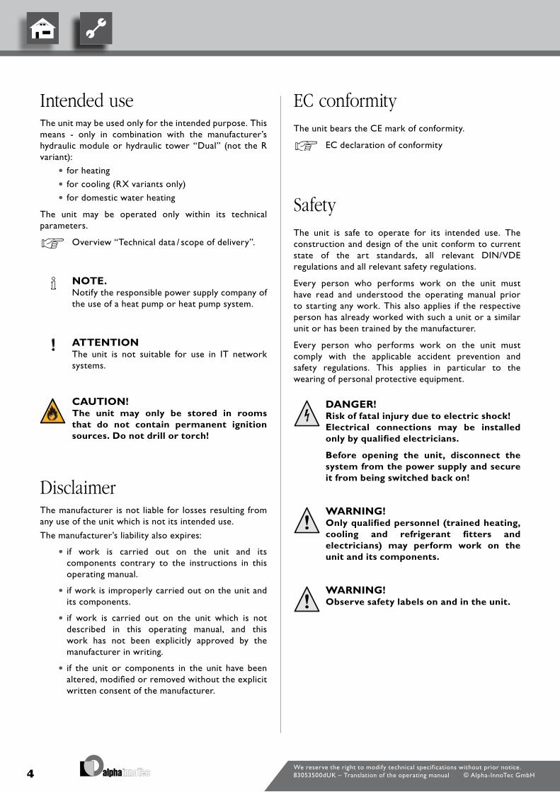
Intended useThe unit may be used only for the intended purpose. This means - only in combination with the manufacturer’s hydraulic module or hydraulic tower “dual” (not the R variant):
• for heating
• for cooling (RX variants only)
• for domestic water heating
The unit may be operated only within its technical parameters.
overview “Technical data / scope of delivery”.
note. Notify the responsible power supply company of
the use of a heat pump or heat pump system.
attentIon The unit is not suitable for use in IT network
systems.
CautIon! the unit may only be stored in rooms
that do not contain permanent ignition sources. Do not drill or torch!
DisclaimerThe manufacturer is not liable for losses resulting from any use of the unit which is not its intended use.
The manufacturer’s liability also expires:
• if work is carried out on the unit and its components contrary to the instructions in this operating manual.
•if work is improperly carried out on the unit and its components.
• if work is carried out on the unit which is not described in this operating manual, and this work has not been explicitly approved by the manufacturer in writing.
• if the unit or components in the unit have been altered, modified or removed without the explicit written consent of the manufacturer.
eC conformityThe unit bears the cE mark of conformity.
Ec declaration of conformity
safetyThe unit is safe to operate for its intended use. The construction and design of the unit conform to current state of the art standards, all relevant dIN/vdE regulations and all relevant safety regulations.
Every person who performs work on the unit must have read and understood the operating manual prior to starting any work. This also applies if the respective person has already worked with such a unit or a similar unit or has been trained by the manufacturer.
Every person who performs work on the unit must comply with the applicable accident prevention and safety regulations. This applies in particular to the wearing of personal protective equipment.
Danger! risk of fatal injury due to electric shock! electrical connections may be installed
only by qualified electricians.
Before opening the unit, disconnect the system from the power supply and secure it from being switched back on!
WarnIng! only qualified personnel (trained heating,
cooling and refrigerant fitters and electricians) may perform work on the unit and its components.
WarnIng! observe safety labels on and in the unit.

5We reserve the right to modify technical specif ications without prior notice.83053500dUK – Translation of the operating manual © Alpha-InnoTec GmbH
WarnIng! unit contains flammable refrigerants! If refrigerant leaks an explosion hazard is
caused. If this happens:
– shut down unit.
– notify the manufacturer’s authorised service centre.
- Keep ignition sources away.
attentIon for safety reasons: Never disconnect the unit from the power sup-
ply, unless the unit is being opened.
attentIon Install the heat pump only outdoors and operate
only with outside air as the heat source. do not restrict or block the air-conducting sides.
dimensional drawing and installation plan for respective model.
WarnIng! never switch on unit if façade parts on the
unit are removed.
attentIon It is not permitted to integrate the heat pump in
ventilation systems. The use of the cooled air for cooling purposes is not permitted.
attentIon The ambient air at the place in which the heat
pump is installed, as well as the air drawn in as a heat source, must not contain any corrosive constituents!
constituents (such as ammonia, sulphur, chlo-rine, salt, sewage gases, flue gases…) can cause damage to the heat pump, which can lead to complete failure / irreparable damage to the heat pump!
Customer servicefor technical information please contact a qualified technician or the manufacturer’s local partner.
overview “customer service”.
Warranty / Guaranteefor warranty and guarantee conditions, please refer to the purchase documents.
note. please contact your dealer concerning warran-
ties and guarantees.
DisposalWhen decommissioning the unit, always comply with applicable laws, directives and standards for the recovery, recycling and disposal of materials and components of cooling units.
“dismantling”.
6We reserve the right to modify technical specif ications without prior notice.83053500dUK – Translation of the operating manual © Alpha-InnoTec GmbH
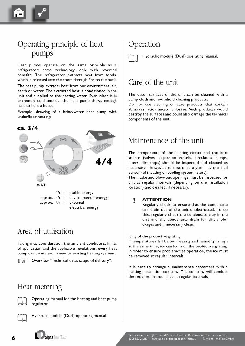
Operating principle of heat pumps
Heat pumps operate on the same principle as a refrigerator: same technology, only with reversed benefits. The refrigerator extracts heat from foods, which is released into the room through fins on the back.
The heat pump extracts heat from our environment: air, earth or water. The extracted heat is conditioned in the unit and supplied to the heating water. Even when it is extremely cold outside, the heat pump draws enough heat to heat a house.
Example: drawing of a brine/water heat pump with underfloor heating:
4/4 = usable energyapprox. 3/4 = environmental energyapprox. 1⁄4 = external
electrical energy
area of utilisationTaking into consideration the ambient conditions, limits of application and the applicable regulations, every heat pump can be utilised in new or existing heating systems.
overview “Technical data / scope of delivery”.
Heat metering operating manual for the heating and heat pump
regulator.
Hydraulic module (dual) operating manual.
Operation Hydraulic module (dual) operating manual.
Care of the unitThe outer surfaces of the unit can be cleaned with a damp cloth and household cleaning products.do not use cleaning or care products that contain abrasives, acids and/or chlorine. Such products would destroy the surfaces and could also damage the technical components of the unit.
maintenance of the unitThe components of the heating circuit and the heat source (valves, expansion vessels, circulating pumps, filters, dirt traps) should be inspected and cleaned as necessary - however, at least once a year - by qualified personnel (heating or cooling system fitters).The intake and blow-out openings must be inspected for dirt at regular intervals (depending on the installation location) and cleaned, if necessary.
attentIon Regularly check to ensure that the condensate
can drain out of the unit unobstructed. To do this, regularly check the condensate tray in the unit and the condensate drain for dirt / blo-ckages and if necessary clean.
Icing of the protective gratingIf temperatures fall below freezing and humidity is high at the same time, ice can form on the protective grating. In order to ensure problem-free operation, the ice must be removed at regular intervals.
It is best to arrange a maintenance agreement with a heating installation company. The company will conduct the required maintenance at regular intervals.

7We reserve the right to modify technical specif ications without prior notice.83053500dUK – Translation of the operating manual © Alpha-InnoTec GmbH
WarnIng! Do not use any objects, other than those
allowed by the manufacturer, to accelerate the thawing process.
note. Any person who works on the refrigerant circuit
must have a qualification certificate issued by a body accredited by the industry.
CleaningandflushingofunitComponents
CautIon! unit components may be cleaned
and flushed only by customer service personnel authorised by the manufacturer. use only liquids recommended by the manufacturer.
rinsing of the liquefier with chemical cleaning agents must be followed by neutralisation of residue and intensive flushing with water. always observe the technical data of the manufacturer of the heat exchanger.
malfunctionsIn the event of a fault, you can read out the cause of the fault from the diagnostic program of the heating and heat pump regulator.
operating manual of the heating and heat pump regulator.
WarnIng! only customer service personnel
authorised by the manufacturer may carry out service and repair work on the components of the unit.
overview “customer service”.
8We reserve the right to modify technical specif ications without prior notice.83053500dUK – Translation of the operating manual © Alpha-InnoTec GmbH
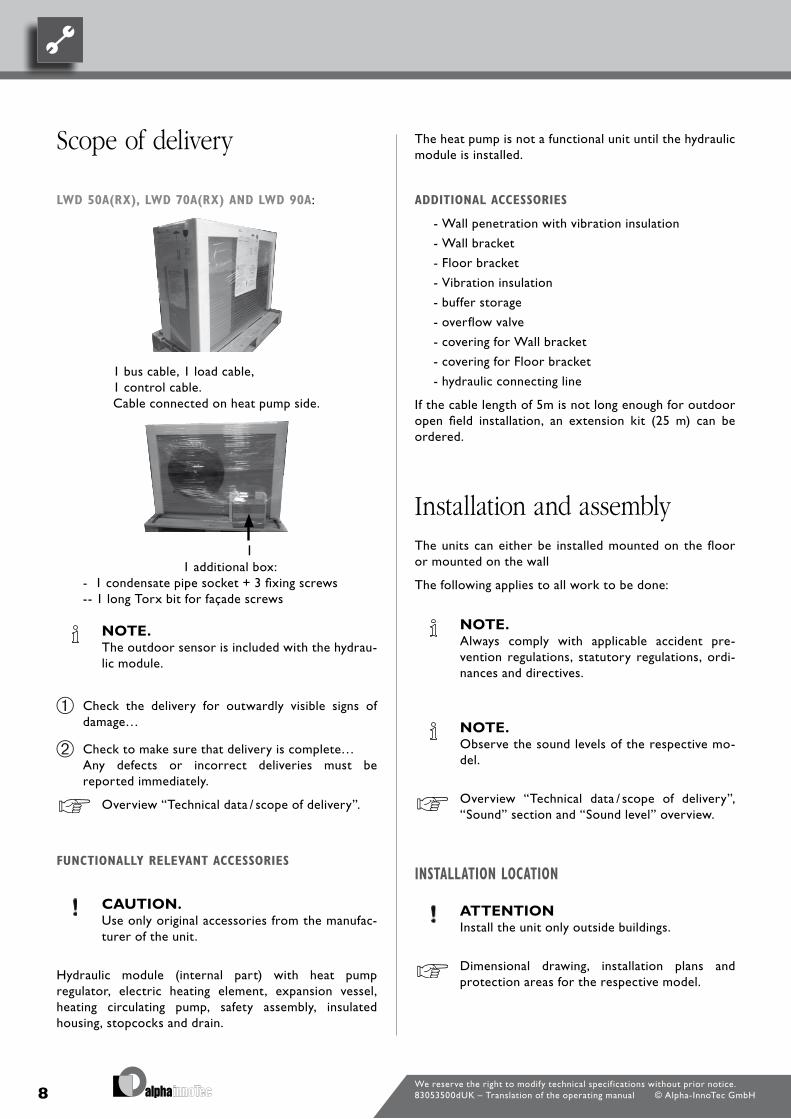
scope of delivery
lWd50a(RX),lWd70a(RX)andlWd90a:
1 bus cable, 1 load cable, 1 control cable.cable connected on heat pump side.
1 additional box:- 1 condensate pipe socket + 3 fixing screws-- 1 long Torx bit for façade screws
note. The outdoor sensor is included with the hydrau-
lic module.
check the delivery for outwardly visible signs of damage…
check to make sure that delivery is complete… Any defects or incorrect deliveries must be
reported immediately.
overview “Technical data / scope of delivery”.
funCtionallyRelevantaCCessoRies
CautIon. Use only original accessories from the manufac-
turer of the unit.
Hydraulic module (internal part) with heat pump regulator, electric heating element, expansion vessel, heating circulating pump, safety assembly, insulated housing, stopcocks and drain.
The heat pump is not a functional unit until the hydraulic module is installed.
additionalaCCessoRies
- Wall penetration with vibration insulation
- Wall bracket
- floor bracket
- vibration insulation
- buffer storage
- overflow valve
- covering for Wall bracket
- covering for floor bracket
- hydraulic connecting line
If the cable length of 5m is not long enough for outdoor open field installation, an extension kit (25 m) can be ordered.
Installation and assemblyThe units can either be installed mounted on the floor or mounted on the wall
The following applies to all work to be done:
note. Always comply with applicable accident pre-
vention regulations, statutory regulations, ordi-nances and directives.
note. observe the sound levels of the respective mo-
del.
overview “Technical data / scope of delivery”, “Sound” section and “Sound level” overview.
installationloCation
attentIon Install the unit only outside buildings.
dimensional drawing, installation plans and protection areas for the respective model.

9We reserve the right to modify technical specif ications without prior notice.83053500dUK – Translation of the operating manual © Alpha-InnoTec GmbH
tRanspoRttoinstallationloCation
To prevent damage during transport, always transport the unit to final installation location in its original packaging, using a lifting truck, forklift or crane.
note. The unit is delivered on a pallet with fixing rails.
The fixing rails can be used for transport.
CautIon. always wear protective gloves if using the
fixing rail for transport!
1 fixing rail
CautIon! several people are required to transport
the unit. Do not underestimate the weight of the unit.
overview “Technical data / scope of delivery”, “General unit data” section.
attentIon Never use components and hydraulic connec-
tions on the unit for transport purposes.
attentIon do not tilt the unit more than a maximum of 45°
(in any direction).
installation
pRepaRingtheinstallation,togetheRWiththeWallpenetRation
To connect the outdoor unit with the indoor part (hydraulic module), an opening must be provided for the wall penetration (accessory) or a hole must be made to enable the KG pipe Ø125 mm (= accessory Wall penetration) to be installed.
If the wall penetration is not yet available, it is possible to work in advance using a standard KG pipe, 1m long dN 125.
note. Always keep to the installation plan for the re-
spective model. observe minimum spacings and protection areas.
Installation plan and dimensional drawings and protection areas for the respective model.
CautIon. In the air outlet area the air temperature
is ca. 5 K below the ambient temperature. under certain climatic conditions, therefore, an ice layer can form in the air outlet area.
Install the heat pump so that the air blower does not blow in the direction of footpaths.
CautIon. several people are required to install the
unit.
note. The ground surface in the air outlet area of the
heat pump must be permeable to water.
note. Always ensure you keep to the specified distance
from the wall, from wall openings, windows, light wells and similar.
See “dimensional drawings and protection areas”.
note. If the wall penetration is not used, the LIn
bus cable must be laid through a separate conduit, separated from the other cables.
the two other cables must also be laid on site using reserve conduits.
note. always ensure minimum wall area is
available. always keep to the installation plan. note
and keep to minimum spacings.

10We reserve the right to modify technical specif ications without prior notice.83053500dUK – Translation of the operating manual © Alpha-InnoTec GmbH
outdoors:
connect the condensate pipe (wall penetration accessory) to the condensate connection socket.
807318
Artikel-Nr.:15070001
1
1x
1x
A B C
1x
E G
2x
D
1x
H J KF
N O P T U
4x 1x1x 1x2x
6x 4x 1x 1x 3x
2
3
4x G
2xB
I
2x
20
A
4
5
R S
1x2x
76
i
200
P
P
20
i
G
V
1x
L
M
1x
1°
6x
10
See “Wall penetration installation instructions”.
The condensate pipe may not be laid alone; it must be inserted into a second pipe suitable for laying in the ground (for example, KG pipe), before it is lowered into the ground!The connection of both pipes must be sealed. It must be possible to adjust the length. The pipe at the unit must not sit on the ground, but must be able to be moved.
attentIon Ensure adequate percolation of the discharged
condensate into the ground!
To the inside: Insert the condensate pipe (wall penetration
accessory) through the wall penetration (accessory- use lubricant) and connect to the supplied plastic elbow at the condensate connection socket.
See “Wall penetration installation instructions”.
note. If the condensate pipe is not laid to the inside,
the openings in the wall penetration at the front and back must be closed off with the plugs sup-plied.
installationWithWallbRaCket
See “Installation instructions wall bracket”..
See ”Wall penetration installation instructions”.
See “Installation plans/minimum spacings/drilling pattern”.
The wall bracket is only suitable for solid. load-bearing walls. In the case of wooden stud walls with panelling the floor-mounted bracket should be used to avoid possible structurally-borne sound transfer to the interior rooms
installationonflooRbRaCket
It is possible to install the unit near a wall or in an open space. The heat pump should ideally be installed in a wind-protected position. If this is not possible it is advisable to install it transversely to the main wind direction or air routing with the main wind direction.
place the unit on a solid, level and load-bearing foundation. The foundation must not be connected to the building. make sure that the foundation is designed for the weight of the heat pump.
See “Installation instructions floor bracket”.
See “Wall penetration installation instructions”.
See “Installation plans/minimum spacings/view of foundation”.
note. If installing with wall penetration, ensure the
correct distance from the wall is maintained.
CondensatedRain
The condensate from the air must be discharged frost-free through a plastic condensate pipe with a minimum diameter of 40 mm. If subsoils are permeable to water, it is sufficient to lay the condensate pipe vertically at least 90 cm into the ground.
Use the screws provided to install the condensate connection socket, included with the unit, to the condensate drain at the underside of the unit.

11We reserve the right to modify technical specif ications without prior notice.83053500dUK – Translation of the operating manual © Alpha-InnoTec GmbH
ConneCtiontotheheatingCiRCuit
flush heating circuit thoroughly before connecting the unit to the heating circuit…
note. Contamination and deposits in the heating
circuit can cause malfunctions.
Install shut-off devices for the hot water outflow (forward flow) and hot water inflow (return flow) on the heat pump side.
attentIon connect the unit to the heating circuit according
to the hydraulic diagram for the respective model.
“Hydraulic connection” instructions.
note. check to make sure that the diameters and
lengths of the pipes for the heating circuit (in-cluding the pipes laid in the ground between the heat pump and the building!) are adequately di-mensioned.
push the sealing plate supplied into the recess in the housing floor:
1 Sealing plate2 leadthroughs for heating water 3 leadthroughs for electric cables
attentIon When installing the connections, always secure
the connections on the unit against twisting, to prevent damage to the copper pipes inside the unit.
connect the unit to the fixed piping of the heating circuit via vibration decouplers (vibration installation - stainless steel corrugated pipes, accessory). you must install them to prevent the
transfer of structural borne sound to the fixed piping.
See “Installation instructions vibration insulation”.
1 connection, heating water outlet (forward flow)
2 connection, heating water inlet (return flow) 3 condensation water pipe
vibration insulation (accessory or wall penetration scope of delivery):
feed the stainless steel corrugated pipes through the seal in the bottom of the housing and screw onto the two pipes in the wall penetration.
Install flow line first, then return flow.
CautIon. If a wall penetration is not used, then lay the
outdoor fixed piping of the heating circuit below the frost limit in the ground.

12We reserve the right to modify technical specif ications without prior notice.83053500dUK – Translation of the operating manual © Alpha-InnoTec GmbH
eleCtRiCalConneCtions
The following applies to all work to be done:
Danger! risk of fatal injury due to electric shock! all electrical connections must be carried
out by qualified electricians only. Before opening the unit, disconnect the
system from the power supply and secure it from being switched back on!
WarnIng! During installation and while carrying out
electrical work, comply with the relevant en-, vDe and/or local safety regulations.
Comply with technical connection requirements of the responsible power supply company (if required by the latter)!
attentIon. Ensure clockwise rotary field of the load power
supply (compressor). operation with incorrect rotary direction of the
compressor can cause serious, irreparable da-mage to the compressor.
attentIon. The power supply for the heat pump must be
equipped with a three-phase automatic circuit-breaker with at least 3mm contact spacing to IEc 60947-2.
Note the level of the tripping current.
overview “Technical data / scope of delivery”, “Electrics” section.
See “operating instructions hydraulic module or hydraulic module dual or hydraulic tower dual”.
Pressure relief See “operating instructions hydraulic module”,
“Safety assembly, expansion vessel” section.
Overflow valveAlways use an overflow valve for tanks integrated in series to ensure the minimum flow rate of the heating circuit volume flow through the heat pump. The overflow valve must be dimensioned so that the minimum flow rate of the volume flow through the heat pump is ensured when the heating circuit is shut off.
Buffer tankThe hydraulic connection of the heat pump requires a buffer tank in the heating circuit.minimum size 60l.only one separating tank integration (vapour diffusion insulated) is allowed for the lWd 50A/RX and lWd 70A/RX.
“Hydraulic connections” documents
Circulating pumps
inthehydRauliCmodule.
“Hydraulic module or hydraulic module dual” operating manual.
Domestic water heatingWater heating with the heat pump requires an additional hot water circuit, parallel to the heating circuit. When installing, make sure that the domestic hot water charge is not fed through the buffer tank of the heating circuit.
“Hydraulic connection” instructions.

13We reserve the right to modify technical specif ications without prior notice.83053500dUK – Translation of the operating manual © Alpha-InnoTec GmbH
rinsing, filling and bleeding the system
See “operating instructions, hydraulic module or hydraulic module dual”.
CautIon. The system must be absolutely free from air be-
fore commissioning.
WateRqualityofthefillandadditionalWateRinhotWateRheatingsystemsaCCoRdingtovdi2035paRtiandii
Use of modern, energy-efficient heat pump systems is becoming increasingly widespread. Their ingenious technology enables these systems to achieve very good efficiencies. The decreasing space available for heat generators has led to the development of compact units with increasingly smaller cross-sections and high capacities. This means the complexity of the systems and the material diversity are also increasing, which plays an important role especially in their corrosion behaviour. The heating water not only affects the efficiency of the system, but also the life of the heat generator and the heating components of a system.
The guide values of vdI 2035 part I and part II must therefore be complied with as minimum requirements for proper operation of the systems. our practical experience has shown that the safest and most trouble-free running of the systems is achieved with so-called low-salt operation.
vdI 2035 part I gives important information and recommendations regarding scaling and its prevention in heating and domestic hot water heating systems.
vdI 2035 part II primarily deals with the requirements for reducing heating water corrosion in hot water heating systems.
pRinCiplesofpaRtiandpaRtii
The occurrence of scaling and corrosion damage in hot water heating systems is low, if
- proper planning and commissioning is carried out
- the system is closed in corrosion terms
- adequately dimensioned pressurising is integrated
- the guide values for the heating water are complied with
- and regular servicing and maintenance are carried out.
Domestic hot water tankIf the heat pump is to be used for domestic water heating, you must integrate special domestic hot water tanks in the heat pump system. choose a storage volume so that the required quantity of hot water is available even during a power cut.
note. The heat exchanger surface of the domestic hot
water tank must be dimensioned so that the he-ating capacity of the heat pump is transferred with minimum spread.
We offer a variety of domestic hot water tanks for you to choose from. They are optimised for use with your heat pump.
note. Integrate the hot-water tank in the heat pump
system according to the hydraulic diagram for your system.
“Hydraulic connection” instructions.

14We reserve the right to modify technical specif ications without prior notice.83053500dUK – Translation of the operating manual © Alpha-InnoTec GmbH
only way to comply with the vdI 2035 requirements and the recommendations and installation instructions of the heat pump manufacturer.
part 2 of vdI 2035 also points out the reduction in total salt content (conductivity). The risk of corrosion is far lower if deionised water is used than is the case if the system is operated with salty, i.e. softened water.
Even if the water has been softened beforehand, it contains dissolved, corrosion-promoting salts, which act as electrolytes due to the use of different materials in the heating system and therefore accelerate corrosion processes. This can ultimately result in pitting.
contamination and deposits in the heating circuit can cause malfunctions
Rinse,fillandbleedtheheatingCiRCuitandhotWateRbuffeRtank
To bleed the hot water tank, the heating circuit and hot water circuit must be rinsed simultaneously.
onthesafesideWithloW-saltopeRation
The problems listed above do not occur at all with low-salt operation, as neither corrosive salts such as sulphates, chlorides and nitrates nor alkalising sodium hydrogen carbonate are in the heating water. The corrosive properties of deionised water are very low and in addition, fur cannot form in the boiler. This is the ideal approach for closed heating circuits, in particular, because low oxygen input into the heating circuit can also be tolerated.
In general, when the system is filled with deionised water, the pH value sets itself within the ideal range due to “self-alkalinisation”. If necessary, a pH value of 8.2 can be very easily alkalised by adding chemicals. In this way, optimum protection of the entire heating system is achieved.
monitoRing
Analytical recording and monitoring of the relevant water values and the added active conditioning substances is of decisive importance. Therefore, they should be monitored regularly using appropriate water test equipment.
fill and bleed the heating circuit…
In addition, open the bleeding valve on the condenser of the heat pump. bleed condenser…
A system log should be kept, in which the relevant planning data is entered (vdI 2035).
damagethatCanoCCuRinCaseofnon-ComplianCe
- malfunctions and the failure of components (e.g. pumps, valves)
- Internal and external leaks (e.g. from heat exchangers)
- cross-section reduction and blockaging of components (e.g. heat exchanger, pipes, pumps)
- material fatigue
- Gas bubbles and gas cushion formation (cavitation)
- Negative effect on heat transfer (formation of coatings, deposits) and associated noises (e.g. boiling noises, flow noises)
limesCale–theeneRgykilleR
filling with untreated drinking water inevitably leads to the precipitation of all calcium as scale. The consequence: limescale deposits form on the heat transfer surfaces of the heating. The efficiency falls and the energy costs rise. A rule of thumb is that 1 millimetre of limescale deposit causes an energy loss of 10%. In extreme cases it can even cause damage to the heat exchangers.
WateRsofteningtovdi2035–paRti
If the water is softened before the heating is filled, in accordance with the vdI 2035 guidelines, no scale can form. This effectively and permanently prevents limescale deposits and the resulting negative effects on the entire heating system.
CoRRosion–anundeRestimatedpRoblem
vdI 2035, part II, deals with the problem of corrosion. Softening the heating water can prove to be insufficient. The pH value can significantly exceed the limit of 10. pH values higher than 11 can set in, which even damage rubber seals. The vdI 2035, part 1 guidelines are fulfilled, however, vdI 2035, part 2 suggests a pH value between 8.2 and maximum 10.
If aluminium materials are used, which is the case in many modern heating systems, a pH value of 8.5 must not be exceeded, because otherwise there is a threat of corrosion – and aluminium is attacked without the presence of oxygen. Therefore, apart from softening the heating fill and additional water, the heating water should also be appropriately conditioned. This is the

15We reserve the right to modify technical specif ications without prior notice.83053500dUK – Translation of the operating manual © Alpha-InnoTec GmbH
Insulating the hydraulic connections
Insulate the piping of the heating circuit and the condensate pipe in the outdoor area so that they are frost-proof, vapour-diffusion tight and Uv resistant.
note. Insulate in accordance with applicable local stan-
dards and guidelines.
check all hydraulic connections for leaks. perform leak test…
Insulate all connections and pipes of the heat circuit (RX-variants vapour diffusion insulated).
Commissioning
WarnIng! the unit may only be started up if the
façade / facing panels are closed.
note. The commissioning has to be in the heating
mode.
Thoroughly check the installation and work through the items on the general checklist…
“General checklist”.
by checking the installation you prevent damage to the heat pump system that could be caused by incorrect installation work.
Ensure…
• clockwise rotary field of the load power supply (compressor).
• the heat pump installation and assembly is according to the requirements in this operating manual.
• the electrical installation work has been properly completed.
• a three-phase automatic circuit breaker has been installed for the compressor. It must have at least 3 mm contact gap according to IEc 60941-2.
• The heating circuit is flushed, filled and thoroughly bled.
• All valves and shut-off devices of the heating circuit are open.
• all pipe systems and components of the system are sealed.
carefully fill out and sign the completion report for heat pump systems…
In Germany and Austria: Send completion report for heat pump systems
and general checklist to the manufacturer’s factory customer service department.
In other countries: Send completion report for heat pump systems
and general checklist to the manufacturer’s local partner.
overview “customer service”.
16We reserve the right to modify technical specif ications without prior notice.83053500dUK – Translation of the operating manual © Alpha-InnoTec GmbH
The heat pump system will be commissioned by customer service personnel authorised by the manufacturer. There is a fee for commissioning!
Dismantling
Danger! risk of fatal injury due to electric shock! electrical connections may be installed
only by qualified electricians.
Before opening the unit, disconnect the system from the power supply and secure it from being switched back on!
WarnIng! unit contains flammable refrigerants! If refrigerant leaks, an explosion hazard is
caused. If this happens:
– shut down unit.
– notify the manufacturer’s authorised service centre.
– Keep ignition sources away.
WarnIng! only qualified heating or cooling system
technicians are allowed to remove the unit from the system.
note. Any person who works on the refrigerant circuit
must have a qualification certificate issued by a body accredited by the industry.
attentIon Recycle or provide for proper disposal of unit
components, refrigerants and oil in accor-dance with the applicable regulations, standards, guidelines and directives.
WithdRaWalfRomseRviCe
It is particularly important that the technician responsible for the withdrawal from service work is familiar with all details of the disposal equipment. We recommend that all refrigerant be recovered.
before disposing of the drained fluids, take samples of the oil and refrigerant, if the refrigerant is to be treated for reuse.
note. It is important for electricity to be available
where the work is to be carried out.
a) familiarise yourself with the units and their function.
b) disconnect the unit to be disposed of from the power supply.
c) before starting the disposal procedure, ensure that:
- mechanical aids required for the transport of refrigerant cylinders are available if necessary;
- personal protective equipment is available and is properly used;
- the extraction process is continuously monitored by a competent person;
- the disposal station and refrigerant cylinders conform to the relevant guidelines and directives.
d) If possible, carry out a pump-down cycle.
e) If it is not possible to establish a vacuum, extract through a collection pipe, so that refrigerant can be removed from all parts of the system.
f) Ensure that the refrigerant cylinder is on the scales before starting the extraction.
g) Switch on the disposal equipment and continue according to the manufacturer’s instructions.
h) Ensure that recycling cylinders are not overfilled (never more than 80 % of the liquid fill quantity).
i) Never exceed the allowable operating pressure of the recycling cylinder, not even for a short time.
j) When the recycling cylinders are properly filled and the process has been completed, ensure that the cylinders and units are immediately removed from the system and all shut-off valves are closed.
k) Recovered refrigerant cannot be used in other systems until it has been cleaned and examined.
maRkings
Units must be appropriately marked or labelled so that it is clear to all that they have been withdrawn from service and the refrigerant has been removed. This marking must be dated and signed. Ensure that information regarding flammable refrigerant is attached to the units.

17We reserve the right to modify technical specif ications without prior notice.83053500dUK – Translation of the operating manual © Alpha-InnoTec GmbH
ReCoveRy/ReCyCling
If refrigerant is extracted for repair or withdrawal from service purposes, ensure that this is done safely. If coolant is transferred into cylinders, ensure that only suitable refrigerant cylinders are used. Ensure that a sufficient number of refrigerant cylinders are available for the quantity in the system. All refrigerant cylinders used must be intended for the refrigerant to be extracted and marked accordingly (i.e. special recycling cylinders for the recovery and recycling of refrigerant). The refrigerant cylinders must have a safety valve and securely attached shut-off valves and be in a good condition. Empty recycling cylinders are evacuated and should be cooled before the extraction process, if possible. The disposal equipment must be in a good condition and suitable for the recovery of flammable refrigerants. Instructions on the individual recovery procedure steps must be enclosed with the equipment. In addition, calibrated scales must be available and must also be in good condition. Hoses must be equipped with leak-free couplings and be in good condition. before the disposal equipment is used, check that it is in good condition, that it has been serviced at the specified intervals and that the corresponding electrical devices are sealed to prevent ignition in case of refrigerant leaks. In case of doubt, contact the manufacturer for advice. The recovered refrigerant must be returned to the supplier in a proper recycling cylinder. do not mix refrigerants in refrigerant cylinders. If compressors or compressor oil is to be disposed of, ensure that they are evacuated with an adequate vacuum to ensure that there is no longer any flammable refrigerant in the oil. before the compressor is returned to the manufacturer it must be evacuated. This process may only be accelerated by means of electrical heating of the compressor housing. When oil is drained from a system, it must be done with appropriate caution.

18
GerätebezeichnungHeat pump type Brine/water ı Air/water ı Water/water • applicable ı — not applicable
Installation location Indoors ı Outdoors • applicable ı — not applicable
Conformity CE
Performance data Heating capacity/COP at
A7/W35 Standard point acc. to EN14511 2 compressors 1 compressor "kW ı … kW ı …"
A7/W45 Standard point to EN14511 2 compressors 1 compressor "kW ı … kW ı …"
A2/W35 Operating point to EN14511 2 compressors 1 compressor "kW ı … kW ı …"
A10/W35 Operating point to EN14511 2 compressors 1 compressor "kW ı … kW ı …"
A-7/W35 Operating point to EN14511 2 compressors 1 compressor "kW ı … kW ı …"
A-15/W65 2 compressors 1 compressor "kW ı … kW ı …"
Limits of application Heating circuit °C
Heat source °C
additional operating points °C
Sound Sound pressure level inside (measured in free field at 1m distance around the machine) dB(A)
External sound pressure level (averaged in free field at 1m distance around air connections) dB(A)
Sound power inside dB
Sound power outside dB
Heat source Air volume flow at maximum external pressure m³/h
Maximum external pressure Pa
Heating circuit Volume flow: minimum flow rate ı nominal flow rate A7/W35 EN14511 ı maximum flow rate l/h
Heat pump pressure loss∆p ı volume flow bar ı l/h
Free compression heat pump ∆p ı volume flow bar ı l/h
Content of buffer tank l
3-way valve, heating/hot water ...
General unit data Dimensions (see dimensional drawing for the specified unit size) unit size
Total weight kg
Connections Heating circuit …
Domestic hot water circuit …
Refrigerant Refrigerant type ı Quantity … ı kg
Free cross section, air ducts mm
Cross section, condensate water hose / length from unit mm ı m
Electrics Voltage code ı three-phase circuit breaker heat pump **) see hydraulic module … ı A
Voltage code ı circuit breaker control voltage **) see hydraulic module … ı A
Voltage code ı circuit breaker electric heating element **) see hydraulic module … ı A
Heat pump Effective power consumption in standard point Az/W35 to EN14511: Power consumption ı current consumption ı cosφ kW ı A ı …
Maximum device current within the limits of application A
Starting current: direct ı with soft starter A ı A
Protection type IP
Output electric heating element 3 ı 2 ı 1 -phase kW ı kW ı kW
Components Heating circuit circulating pump at nominal flow rate: max. power consumption ı current consumption kW ı A
Safety equipment Safety assembly heating circuit ı Safety assembly heat source in scope of delivery: • yes — no
Heating and heat pump regulator Included in scope of delivery: • yes — no
Control and sensor wire Included in scope of delivery: • yes — no
Power cable to unit Included in scope of delivery: • yes — no
Electronic soft starter integrated: • yes — no
Expansion vessels Heating circuit: Scope of delivery ı Volume ı Initial pressure • yes — no ı l ı bar
Overflow valve integrated: • yes — no
Vibration decouplers Heating circuit Included in scope of delivery: • yes — no
UK813517 *) depending on component tolerances and flow **) comply with local regulations n.n. = not detectable w.w. = optional¹) hot water return flow ²) hot water forward flowf
We reserve the right to modify technical specif ications without prior notice.83053500dUK – Translation of the operating manual © Alpha-InnoTec GmbH
technical data / scope of delivery

19
GerätebezeichnungHeat pump type Brine/water ı Air/water ı Water/water • applicable ı — not applicable
Installation location Indoors ı Outdoors • applicable ı — not applicable
Conformity CE
Performance data Heating capacity/COP at
A7/W35 Standard point acc. to EN14511 2 compressors 1 compressor "kW ı … kW ı …"
A7/W45 Standard point to EN14511 2 compressors 1 compressor "kW ı … kW ı …"
A2/W35 Operating point to EN14511 2 compressors 1 compressor "kW ı … kW ı …"
A10/W35 Operating point to EN14511 2 compressors 1 compressor "kW ı … kW ı …"
A-7/W35 Operating point to EN14511 2 compressors 1 compressor "kW ı … kW ı …"
A-15/W65 2 compressors 1 compressor "kW ı … kW ı …"
Limits of application Heating circuit °C
Heat source °C
additional operating points °C
Sound Sound pressure level inside (measured in free field at 1m distance around the machine) dB(A)
External sound pressure level (averaged in free field at 1m distance around air connections) dB(A)
Sound power inside dB
Sound power outside dB
Heat source Air volume flow at maximum external pressure m³/h
Maximum external pressure Pa
Heating circuit Volume flow: minimum flow rate ı nominal flow rate A7/W35 EN14511 ı maximum flow rate l/h
Heat pump pressure loss∆p ı volume flow bar ı l/h
Free compression heat pump ∆p ı volume flow bar ı l/h
Content of buffer tank l
3-way valve, heating/hot water ...
General unit data Dimensions (see dimensional drawing for the specified unit size) unit size
Total weight kg
Connections Heating circuit …
Domestic hot water circuit …
Refrigerant Refrigerant type ı Quantity … ı kg
Free cross section, air ducts mm
Cross section, condensate water hose / length from unit mm ı m
Electrics Voltage code ı three-phase circuit breaker heat pump **) see hydraulic module … ı A
Voltage code ı circuit breaker control voltage **) see hydraulic module … ı A
Voltage code ı circuit breaker electric heating element **) see hydraulic module … ı A
Heat pump Effective power consumption in standard point Az/W35 to EN14511: Power consumption ı current consumption ı cosφ kW ı A ı …
Maximum device current within the limits of application A
Starting current: direct ı with soft starter A ı A
Protection type IP
Output electric heating element 3 ı 2 ı 1 -phase kW ı kW ı kW
Components Heating circuit circulating pump at nominal flow rate: max. power consumption ı current consumption kW ı A
Safety equipment Safety assembly heating circuit ı Safety assembly heat source in scope of delivery: • yes — no
Heating and heat pump regulator Included in scope of delivery: • yes — no
Control and sensor wire Included in scope of delivery: • yes — no
Power cable to unit Included in scope of delivery: • yes — no
Electronic soft starter integrated: • yes — no
Expansion vessels Heating circuit: Scope of delivery ı Volume ı Initial pressure • yes — no ı l ı bar
Overflow valve integrated: • yes — no
Vibration decouplers Heating circuit Included in scope of delivery: • yes — no
UK813517 *) depending on component tolerances and flow **) comply with local regulations n.n. = not detectable w.w. = optional¹) hot water return flow ²) hot water forward flowf
LWD 70A— ı • ı —
— ı ••
— 8,5 ı 4,3
— 8,4 ı 3,5
— 7,7 ı 3,8
— 10, 5 ı 5,1
— 6,3 ı 3,2
— —
20¹ – 62²-20 – 35
A> -7 / 70² —45 —60
3000 —
1200 ı 1600 ı 20000,055 ı 1600
— ı — — — —146G1“ —
R290 ı 1,1 — ı ———
2,0 ı 4,1 ı 0,715,5
— ı 2224
— ı — ı — — ı —— ı —
—•••
— ı — ı ———
813542b
LWD 50A— ı • ı —
— ı ••
— 7,1 ı 4,8
— 6,8 ı 3,8
— 5,6 ı 3,8
— 7,5 ı 5,0
— 4,6 ı 3,2
— —
20¹ – 62²-20 – 35
A> -7 / 70² —45 —60
3000 —
900 ı 1200 ı 15000,066 ı 1200
— ı — — — —141G1“ —
R290 ı 0,95 —
— ı ————
1,5 ı 3,2 ı 0,664
— ı 2024
— ı — ı — — ı —— ı —
—•••
— ı — ı ———
81354b
LWD 90A— ı • ı —
— ı ••
— 10,1 ı 4,12
— 9,9 ı 3,50
— 9,0 ı 3,60
— 11, 3 ı 4,50
— 7,5 ı 3,12
— —
20¹ – 60²-20 – 35
A> -2 / 70² —50 —65
3500 —
1600 ı 2000 ı 25000,076 ı 2000
— ı — — — —149G1“ —
R290 ı 1,17 — ı ———
2,5 ı 5,0 ı 0,727,0
— ı 2424
— ı — ı — — ı —— ı —
—•••
— ı — ı ———
813549
We reserve the right to modify technical specif ications without prior notice.83053500dUK – Translation of the operating manual © Alpha-InnoTec GmbH

20We reserve the right to modify technical specif ications without prior notice.83053500dUK – Translation of the operating manual © Alpha-InnoTec GmbH
GerätebezeichnungHeat pump type Brine/water ı Air/water ı Water/water • applicable ı — not applicable
Installation location Indoors ı Outdoors • applicable ı — not applicable
Conformity CE
Performance dataHeating capacity/COP heat optimised atA7/W35 Standard point as per EN14511 1 compressor kW ı …
A7/W45 1 compressor kW ı …
A2/W35 Operating point as per EN14511 1 compressor kW ı …
A10/W35 Operating point as per EN14511 1 compressor kW ı …
A-7/W35 Operating point as per EN14511 1 compressor kW ı …
Performance dataCooling capacity/EER cool optimised atA27/W18 1 compressor kW ı …
A27/W7 1 compressor kW ı …
A35/W18 1 compressor kW ı …
A35/W7 1 compressor kW ı …
Heating limits of applicationheating circuit (water) °C
Heat source (air) °C
additional operating points °C
Cooling limits cooling circuit (water) °C
Heat sink (air) °C
Sound Sound pressure level outside (averaged in open space at 1 m distance from the machine) dB(A)
Sound power level, outside dB
Heat source Air volume flow m³/h
Maximum external pressure Pa
Heating circuit Volume flow: minimum flow rate ı nominal flow rate A7/W35 EN14511 ı maximum flow rate l/h
Heat pump pressure loss ∆p ı Volume flow bar ı l/h
Free compression heat pump ∆p ı Volume flow bar ı l/h
Content of buffer tank l
3-way valve, heating/hot water ...
General unit dataDimensions (see dimensional drawing for the specified unit size) unit size
Total weight kg
Connections Heating circuit …
Domestic hot water circuit …
Refrigerant Refrigerant type ı Quantity … ı kg
Free cross section, air ducts mm
Cross section, condensate water hose / length from unit mm ı m
Electrics Voltage code ı all-pole circuit breaker heat pump **) see hydraulic module … ı A
Voltage code ı all-pole circuit breaker **) see hydraulic module … ı A
Voltage code ı electric heating element circuit breaker **) see hydraulic module … ı A
Heat pump Effective power consumption in standard point Az/W35 to EN14511: Power consumption ı current consumption ı cosφ kW ı A ı …
Maximum machine current within the use limits A
Starting current: direct ı with soft starter A ı A
Degree of protection IP
Output, electric heating element 3 ı 2 ı 1 phase kW ı kW ı kW
Components Heating circuit circulating pump at nominal flow rate: max. power consumption ı current consumption kW ı ASafety equipment Safety component heating circuit ı Safety component heat source Included in scope of delivery: • yes — no
Heating and heat pump controller Included in scope of delivery: • yes — no
Control and sensor lead Included in scope of delivery: • yes — no
Power cable to unit Included in scope of delivery: • yes — no
Electronic soft starter integrated: • yes — no
Expansion vessels Heating circuit: Scope of delivery ı Volume ı Initial pressure • yes — no ı l ı barOverflow valve integrated: • yes — no
Vibration decouplers Heating circuit Included in scope of delivery: • yes — no
"*) depending on component tolerances and flow n.n. = not detectable w.w. = optional"¹) hot water return ²) hot water feed
technical data / scope of delivery

21We reserve the right to modify technical specif ications without prior notice.83053500dUK – Translation of the operating manual © Alpha-InnoTec GmbH
GerätebezeichnungHeat pump type Brine/water ı Air/water ı Water/water • applicable ı — not applicable
Installation location Indoors ı Outdoors • applicable ı — not applicable
Conformity CE
Performance dataHeating capacity/COP heat optimised atA7/W35 Standard point as per EN14511 1 compressor kW ı …
A7/W45 1 compressor kW ı …
A2/W35 Operating point as per EN14511 1 compressor kW ı …
A10/W35 Operating point as per EN14511 1 compressor kW ı …
A-7/W35 Operating point as per EN14511 1 compressor kW ı …
Performance dataCooling capacity/EER cool optimised atA27/W18 1 compressor kW ı …
A27/W7 1 compressor kW ı …
A35/W18 1 compressor kW ı …
A35/W7 1 compressor kW ı …
Heating limits of applicationheating circuit (water) °C
Heat source (air) °C
additional operating points °C
Cooling limits cooling circuit (water) °C
Heat sink (air) °C
Sound Sound pressure level outside (averaged in open space at 1 m distance from the machine) dB(A)
Sound power level, outside dB
Heat source Air volume flow m³/h
Maximum external pressure Pa
Heating circuit Volume flow: minimum flow rate ı nominal flow rate A7/W35 EN14511 ı maximum flow rate l/h
Heat pump pressure loss ∆p ı Volume flow bar ı l/h
Free compression heat pump ∆p ı Volume flow bar ı l/h
Content of buffer tank l
3-way valve, heating/hot water ...
General unit dataDimensions (see dimensional drawing for the specified unit size) unit size
Total weight kg
Connections Heating circuit …
Domestic hot water circuit …
Refrigerant Refrigerant type ı Quantity … ı kg
Free cross section, air ducts mm
Cross section, condensate water hose / length from unit mm ı m
Electrics Voltage code ı all-pole circuit breaker heat pump **) see hydraulic module … ı A
Voltage code ı all-pole circuit breaker **) see hydraulic module … ı A
Voltage code ı electric heating element circuit breaker **) see hydraulic module … ı A
Heat pump Effective power consumption in standard point Az/W35 to EN14511: Power consumption ı current consumption ı cosφ kW ı A ı …
Maximum machine current within the use limits A
Starting current: direct ı with soft starter A ı A
Degree of protection IP
Output, electric heating element 3 ı 2 ı 1 phase kW ı kW ı kW
Components Heating circuit circulating pump at nominal flow rate: max. power consumption ı current consumption kW ı ASafety equipment Safety component heating circuit ı Safety component heat source Included in scope of delivery: • yes — no
Heating and heat pump controller Included in scope of delivery: • yes — no
Control and sensor lead Included in scope of delivery: • yes — no
Power cable to unit Included in scope of delivery: • yes — no
Electronic soft starter integrated: • yes — no
Expansion vessels Heating circuit: Scope of delivery ı Volume ı Initial pressure • yes — no ı l ı barOverflow valve integrated: • yes — no
Vibration decouplers Heating circuit Included in scope of delivery: • yes — no
"*) depending on component tolerances and flow n.n. = not detectable w.w. = optional"¹) hot water return ²) hot water feed
LWD 50A/RX— ı • ı —
— ı ••
6,8 ı 4,56 6,5 ı 3,62 5,4 ı 3,69 7,2 ı 4,80 4,4 ı 3,11
7,9 ı 4,98 5,9 ı 3,78 7,4 ı 3,97
5,1 ı 2,8920¹ – 62²-20 – 35
A> -7 / 70²7² – 20²15 – 45
4560
3000 —
900 ı 1200 ı 15000,066 ı 1200
— ı — — — —146G1“ —
R290 ı 2,1 —
— ı ————
1,5 ı 3,2 ı 0,66—
— ı 2024
— ı — ı — — ı —— ı —
—•••
— ı — ı ———
813545
LWD 70A/RX— ı • ı —
— ı ••
8,7 ı 4,32 8,8 ı 3,66 7,3 ı 3,68 9,7 ı 4,92 6,0 ı 3,06
11,1 ı 4,59 8,0 ı 3,57 10,1 ı 3,64 7,0 ı 2,74
20¹ – 62²-20 – 35
A> -7 / 70²7² – 20²15 – 45
4560
3000 —
1200 ı 1600 ı 20000,055 ı 1600
— ı — — — —151G1“ —
R290 ı 2,2 —
— ı ————
2,0 ı 4,1 ı 0,715,5
— ı 2224
— ı — ı — — ı —— ı —
—•••
— ı — ı ———
813546
22
Bezeichnung:
Seite: 1/1
a/ - /Mödder / 24.10.2011
Verdichter
Temp„
Qh
Pe
COP
∆p”
VD
Leistungsaufnahme
Coefficient of performance / Leistungszahl
Legende: DE823129L/170408
823165a
“”
Druckverlust Wärmepumpe
Volumenstrom Heizwasser
Temperatur Wärmequelle
Heizleistung
Datei: 823165a Leistungs- Druckverlustkurven LWD 50A.xls
Zeichnungsnummer: 823165a
Änd./Ä.M./Ersteller/Datum
- / PEP006-2011 / Mödder / 13.05.2011
Leistungs-DruckverlustkurvenLWD 50A
0
2
4
6
8
10
12
-20 -15 -10 -5 0 5 10 15 20 25 30 35Temp„ (°C)
Qh (kW)
35°C
50°C
65°C
1
2
3
4
5
6
7
8
-20 -15 -10 -5 0 5 10 15 20 25 30 35Temp„ (°C)
COP
0
1
2
3
-20 -15 -10 -5 0 5 10 15 20 25 30 35Temp„ (°C)
Pe (kW)
0,0
0,1
0,2
0,3
0,4
0,5
0,0 1,0 2,0 3,0
“” (m³/h)
∆p (bar)
”p∆
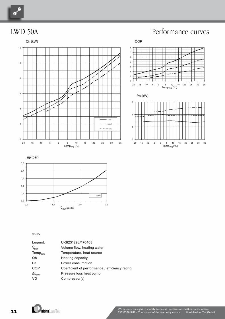
Legend: UK823129L/170408“” Volume flow, heating waterTemp„ Temperature, heat sourceQh Heating capacityPe Power consumptionCOP Coefficient of performance / efficiency rating∆p” Pressure loss heat pumpVD Compressor(s)
We reserve the right to modify technical specif ications without prior notice.83053500dUK – Translation of the operating manual © Alpha-InnoTec GmbH
LWD 50a Performance curves

23
Bezeichnung:
Seite: 1/1
Pe
COP
∆p”
Legende: DE823129L/170408
823166a
- / PEP006-2011 / Mödder / 13.05.2011
Leistungs-DruckverlustkurvenLWD 70A
“”
Druckverlust Wärmepumpe
Volumenstrom Heizwasser
Temperatur Wärmequelle
Heizleistung
Verdichter
Temp„
VD
Leistungsaufnahme
Coefficient of performance / Leistungszahl
Qh
Änd./Ä.M./Ersteller/Datum
a/-/Mödder / 24.10.2011
Datei: 823166 Leistungs- Druckverlustkurven LWD 70A.xls
Zeichnungsnummer: 823166a
0
2
4
6
8
10
12
14
16
-20 -15 -10 -5 0 5 10 15 20 25 30 35Temp„ (°C)
Qh (kW)
35°C
50°C
65°C
1
2
3
4
5
6
7
8
-20 -15 -10 -5 0 5 10 15 20 25 30 35Temp„ (°C)
COP
0
1
2
3
4
-20 -15 -10 -5 0 5 10 15 20 25 30 35Temp„ (°C)
Pe (kW)
0,0
0,1
0,2
0,3
0,4
0,0 1,0 2,0 3,0 4,0
“” (m³/h)
∆p (bar)
”p∆
Legend: UK823129L/170408“” Volume flow, heating waterTemp„ Temperature, heat sourceQh Heating capacityPe Power consumptionCOP Coefficient of performance / efficiency rating∆p” Pressure loss heat pumpVD Compressor(s)
We reserve the right to modify technical specif ications without prior notice.83053500dUK – Translation of the operating manual © Alpha-InnoTec GmbH
Performance curves LWD 70a

24
Qh (kW) COP20
Qh (kW)8
COP20
Qh (kW)
7
8
COP
18
20
Qh (kW)
6
7
8
COP
18
20
Qh (kW)
6
7
8
COP
18
20
Qh (kW)
5
6
7
8
COP
16
18
20
Qh (kW)
4
5
6
7
8
COP
16
18
20
Qh (kW)
3
4
5
6
7
8
COP
16
18
20
Qh (kW)
3
4
5
6
7
8
COP
14
16
18
20
Qh (kW)
2
3
4
5
6
7
8
COP
14
16
18
20
Qh (kW)
1
2
3
4
5
6
7
8
COP
12
14
16
18
20
Qh (kW)
1
2
3
4
5
6
7
8
-20 -15 -10 -5 0 5 10 15 20 25 30 35
COP
12
14
16
18
20
Qh (kW)
1
2
3
4
5
6
7
8
-20 -15 -10 -5 0 5 10 15 20 25 30 35
COP
12
14
16
18
20
Qh (kW)
1
2
3
4
5
6
7
8
-20 -15 -10 -5 0 5 10 15 20 25 30 35Temp„ (°C)
COP
10
12
14
16
18
20
Qh (kW)
1
2
3
4
5
6
7
8
-20 -15 -10 -5 0 5 10 15 20 25 30 35Temp„ (°C)
COP
P (kW)10
12
14
16
18
20
Qh (kW)
1
2
3
4
5
6
7
8
-20 -15 -10 -5 0 5 10 15 20 25 30 35Temp„ (°C)
COP
Pe (kW)10
12
14
16
18
20
Qh (kW)
1
2
3
4
5
6
7
8
-20 -15 -10 -5 0 5 10 15 20 25 30 35Temp„ (°C)
COP
Pe (kW)
8
10
12
14
16
18
20
Qh (kW)
1
2
3
4
5
6
7
8
-20 -15 -10 -5 0 5 10 15 20 25 30 35Temp„ (°C)
COP
5
Pe (kW)
8
10
12
14
16
18
20
Qh (kW)
1
2
3
4
5
6
7
8
-20 -15 -10 -5 0 5 10 15 20 25 30 35Temp„ (°C)
COP
4
5
Pe (kW)
6
8
10
12
14
16
18
20
Qh (kW)
1
2
3
4
5
6
7
8
-20 -15 -10 -5 0 5 10 15 20 25 30 35Temp„ (°C)
COP
4
5
Pe (kW)
6
8
10
12
14
16
18
20
Qh (kW)
1
2
3
4
5
6
7
8
-20 -15 -10 -5 0 5 10 15 20 25 30 35Temp„ (°C)
COP
4
5
Pe (kW)
6
8
10
12
14
16
18
20
Qh (kW)
35°C
1
2
3
4
5
6
7
8
-20 -15 -10 -5 0 5 10 15 20 25 30 35Temp„ (°C)
COP
3
4
5
Pe (kW)
4
6
8
10
12
14
16
18
20
Qh (kW)
35°C
50°C
1
2
3
4
5
6
7
8
-20 -15 -10 -5 0 5 10 15 20 25 30 35Temp„ (°C)
COP
2
3
4
5
Pe (kW)
4
6
8
10
12
14
16
18
20
Qh (kW)
35°C
50°C
65°C
1
2
3
4
5
6
7
8
-20 -15 -10 -5 0 5 10 15 20 25 30 35Temp„ (°C)
COP
2
3
4
5
Pe (kW)
2
4
6
8
10
12
14
16
18
20
Qh (kW)
35°C
50°C
65°C
1
2
3
4
5
6
7
8
-20 -15 -10 -5 0 5 10 15 20 25 30 35Temp„ (°C)
COP
1
2
3
4
5
Pe (kW)
2
4
6
8
10
12
14
16
18
20
Qh (kW)
35°C
50°C
65°C
1
2
3
4
5
6
7
8
-20 -15 -10 -5 0 5 10 15 20 25 30 35Temp„ (°C)
COP
1
2
3
4
5
Pe (kW)
0
2
4
6
8
10
12
14
16
18
20
Qh (kW)
35°C
50°C
65°C
1
2
3
4
5
6
7
8
-20 -15 -10 -5 0 5 10 15 20 25 30 35Temp„ (°C)
COP
0
1
2
3
4
5
Pe (kW)
0
2
4
6
8
10
12
14
16
18
20
-20 -15 -10 -5 0 5 10 15 20 25 30 35
Qh (kW)
35°C
50°C
65°C
1
2
3
4
5
6
7
8
-20 -15 -10 -5 0 5 10 15 20 25 30 35Temp„ (°C)
COP
0
1
2
3
4
5
-20 -15 -10 -5 0 5 10 15 20 25 30 35
Pe (kW)
0
2
4
6
8
10
12
14
16
18
20
-20 -15 -10 -5 0 5 10 15 20 25 30 35Temp„ (°C)
Qh (kW)
35°C
50°C
65°C
1
2
3
4
5
6
7
8
-20 -15 -10 -5 0 5 10 15 20 25 30 35Temp„ (°C)
COP
0
1
2
3
4
5
-20 -15 -10 -5 0 5 10 15 20 25 30 35Temp„ (°C)
Pe (kW)
0
2
4
6
8
10
12
14
16
18
20
-20 -15 -10 -5 0 5 10 15 20 25 30 35Temp„ (°C)
Qh (kW)
35°C
50°C
65°C
1
2
3
4
5
6
7
8
-20 -15 -10 -5 0 5 10 15 20 25 30 35Temp„ (°C)
COP
0
1
2
3
4
5
-20 -15 -10 -5 0 5 10 15 20 25 30 35Temp„ (°C)
Pe (kW)
0
2
4
6
8
10
12
14
16
18
20
-20 -15 -10 -5 0 5 10 15 20 25 30 35Temp„ (°C)
Qh (kW)
35°C
50°C
65°C
1
2
3
4
5
6
7
8
-20 -15 -10 -5 0 5 10 15 20 25 30 35Temp„ (°C)
COP
0
1
2
3
4
5
-20 -15 -10 -5 0 5 10 15 20 25 30 35Temp„ (°C)
Pe (kW)
0
2
4
6
8
10
12
14
16
18
20
-20 -15 -10 -5 0 5 10 15 20 25 30 35Temp„ (°C)
Qh (kW)
35°C
50°C
65°C
1
2
3
4
5
6
7
8
-20 -15 -10 -5 0 5 10 15 20 25 30 35Temp„ (°C)
COP
0
1
2
3
4
5
-20 -15 -10 -5 0 5 10 15 20 25 30 35Temp„ (°C)
Pe (kW)
0 4
∆p (bar)
0
2
4
6
8
10
12
14
16
18
20
-20 -15 -10 -5 0 5 10 15 20 25 30 35Temp„ (°C)
Qh (kW)
35°C
50°C
65°C
1
2
3
4
5
6
7
8
-20 -15 -10 -5 0 5 10 15 20 25 30 35Temp„ (°C)
COP
0
1
2
3
4
5
-20 -15 -10 -5 0 5 10 15 20 25 30 35Temp„ (°C)
Pe (kW)
0 4
∆p (bar)
0
2
4
6
8
10
12
14
16
18
20
-20 -15 -10 -5 0 5 10 15 20 25 30 35Temp„ (°C)
Qh (kW)
35°C
50°C
65°C
1
2
3
4
5
6
7
8
-20 -15 -10 -5 0 5 10 15 20 25 30 35Temp„ (°C)
COP
0
1
2
3
4
5
-20 -15 -10 -5 0 5 10 15 20 25 30 35Temp„ (°C)
Pe (kW)
0,4
∆p (bar)
0
2
4
6
8
10
12
14
16
18
20
-20 -15 -10 -5 0 5 10 15 20 25 30 35Temp„ (°C)
Qh (kW)
35°C
50°C
65°C
1
2
3
4
5
6
7
8
-20 -15 -10 -5 0 5 10 15 20 25 30 35Temp„ (°C)
COP
0
1
2
3
4
5
-20 -15 -10 -5 0 5 10 15 20 25 30 35Temp„ (°C)
Pe (kW)
0 3
0,4
∆p (bar)
0
2
4
6
8
10
12
14
16
18
20
-20 -15 -10 -5 0 5 10 15 20 25 30 35Temp„ (°C)
Qh (kW)
35°C
50°C
65°C
1
2
3
4
5
6
7
8
-20 -15 -10 -5 0 5 10 15 20 25 30 35Temp„ (°C)
COP
0
1
2
3
4
5
-20 -15 -10 -5 0 5 10 15 20 25 30 35Temp„ (°C)
Pe (kW)
0,3
0,4
∆p (bar)
0
2
4
6
8
10
12
14
16
18
20
-20 -15 -10 -5 0 5 10 15 20 25 30 35Temp„ (°C)
Qh (kW)
35°C
50°C
65°C
1
2
3
4
5
6
7
8
-20 -15 -10 -5 0 5 10 15 20 25 30 35Temp„ (°C)
COP
0
1
2
3
4
5
-20 -15 -10 -5 0 5 10 15 20 25 30 35Temp„ (°C)
Pe (kW)
0,3
0,4
∆p (bar)
0
2
4
6
8
10
12
14
16
18
20
-20 -15 -10 -5 0 5 10 15 20 25 30 35Temp„ (°C)
Qh (kW)
35°C
50°C
65°C
1
2
3
4
5
6
7
8
-20 -15 -10 -5 0 5 10 15 20 25 30 35Temp„ (°C)
COP
0
1
2
3
4
5
-20 -15 -10 -5 0 5 10 15 20 25 30 35Temp„ (°C)
Pe (kW)
0 2
0,3
0,4
∆p (bar)
0
2
4
6
8
10
12
14
16
18
20
-20 -15 -10 -5 0 5 10 15 20 25 30 35Temp„ (°C)
Qh (kW)
35°C
50°C
65°C
1
2
3
4
5
6
7
8
-20 -15 -10 -5 0 5 10 15 20 25 30 35Temp„ (°C)
COP
0
1
2
3
4
5
-20 -15 -10 -5 0 5 10 15 20 25 30 35Temp„ (°C)
Pe (kW)
0,2
0,3
0,4
∆p (bar)
0
2
4
6
8
10
12
14
16
18
20
-20 -15 -10 -5 0 5 10 15 20 25 30 35Temp„ (°C)
Qh (kW)
35°C
50°C
65°C
1
2
3
4
5
6
7
8
-20 -15 -10 -5 0 5 10 15 20 25 30 35Temp„ (°C)
COP
0
1
2
3
4
5
-20 -15 -10 -5 0 5 10 15 20 25 30 35Temp„ (°C)
Pe (kW)
0 1
0,2
0,3
0,4
∆p (bar)
0
2
4
6
8
10
12
14
16
18
20
-20 -15 -10 -5 0 5 10 15 20 25 30 35Temp„ (°C)
Qh (kW)
35°C
50°C
65°C
1
2
3
4
5
6
7
8
-20 -15 -10 -5 0 5 10 15 20 25 30 35Temp„ (°C)
COP
0
1
2
3
4
5
-20 -15 -10 -5 0 5 10 15 20 25 30 35Temp„ (°C)
Pe (kW)
0 1
0,2
0,3
0,4
∆p (bar)
0
2
4
6
8
10
12
14
16
18
20
-20 -15 -10 -5 0 5 10 15 20 25 30 35Temp„ (°C)
Qh (kW)
35°C
50°C
65°C
1
2
3
4
5
6
7
8
-20 -15 -10 -5 0 5 10 15 20 25 30 35Temp„ (°C)
COP
0
1
2
3
4
5
-20 -15 -10 -5 0 5 10 15 20 25 30 35Temp„ (°C)
Pe (kW)
0,1
0,2
0,3
0,4
∆p (bar)
0
2
4
6
8
10
12
14
16
18
20
-20 -15 -10 -5 0 5 10 15 20 25 30 35Temp„ (°C)
Qh (kW)
35°C
50°C
65°C
1
2
3
4
5
6
7
8
-20 -15 -10 -5 0 5 10 15 20 25 30 35Temp„ (°C)
COP
0
1
2
3
4
5
-20 -15 -10 -5 0 5 10 15 20 25 30 35Temp„ (°C)
Pe (kW)
0,0
0,1
0,2
0,3
0,4
∆p (bar)
0
2
4
6
8
10
12
14
16
18
20
-20 -15 -10 -5 0 5 10 15 20 25 30 35Temp„ (°C)
Qh (kW)
35°C
50°C
65°C
1
2
3
4
5
6
7
8
-20 -15 -10 -5 0 5 10 15 20 25 30 35Temp„ (°C)
COP
0
1
2
3
4
5
-20 -15 -10 -5 0 5 10 15 20 25 30 35Temp„ (°C)
Pe (kW)
0,0
0,1
0,2
0,3
0,4
0,0 1,0 2,0 3,0 4,0
∆p (bar)
0
2
4
6
8
10
12
14
16
18
20
-20 -15 -10 -5 0 5 10 15 20 25 30 35Temp„ (°C)
Qh (kW)
35°C
50°C
65°C
1
2
3
4
5
6
7
8
-20 -15 -10 -5 0 5 10 15 20 25 30 35Temp„ (°C)
COP
0
1
2
3
4
5
-20 -15 -10 -5 0 5 10 15 20 25 30 35Temp„ (°C)
Pe (kW)
0,0
0,1
0,2
0,3
0,4
0,0 1,0 2,0 3,0 4,0
∆p (bar)
0
2
4
6
8
10
12
14
16
18
20
-20 -15 -10 -5 0 5 10 15 20 25 30 35Temp„ (°C)
Qh (kW)
35°C
50°C
65°C
1
2
3
4
5
6
7
8
-20 -15 -10 -5 0 5 10 15 20 25 30 35Temp„ (°C)
COP
0
1
2
3
4
5
-20 -15 -10 -5 0 5 10 15 20 25 30 35Temp„ (°C)
Pe (kW)
0,0
0,1
0,2
0,3
0,4
0,0 1,0 2,0 3,0 4,0
“” (m³/h)
∆p (bar)
0
2
4
6
8
10
12
14
16
18
20
-20 -15 -10 -5 0 5 10 15 20 25 30 35Temp„ (°C)
Qh (kW)
35°C
50°C
65°C
1
2
3
4
5
6
7
8
-20 -15 -10 -5 0 5 10 15 20 25 30 35Temp„ (°C)
COP
0
1
2
3
4
5
-20 -15 -10 -5 0 5 10 15 20 25 30 35Temp„ (°C)
Pe (kW)
0,0
0,1
0,2
0,3
0,4
0,0 1,0 2,0 3,0 4,0
“” (m³/h)
∆p (bar)
0
2
4
6
8
10
12
14
16
18
20
-20 -15 -10 -5 0 5 10 15 20 25 30 35Temp„ (°C)
Qh (kW)
35°C
50°C
65°C
1
2
3
4
5
6
7
8
-20 -15 -10 -5 0 5 10 15 20 25 30 35Temp„ (°C)
COP
0
1
2
3
4
5
-20 -15 -10 -5 0 5 10 15 20 25 30 35Temp„ (°C)
Pe (kW)
0,0
0,1
0,2
0,3
0,4
0,0 1,0 2,0 3,0 4,0
“” (m³/h)
∆p (bar)
0
2
4
6
8
10
12
14
16
18
20
-20 -15 -10 -5 0 5 10 15 20 25 30 35Temp„ (°C)
Qh (kW)
35°C
50°C
65°C
1
2
3
4
5
6
7
8
-20 -15 -10 -5 0 5 10 15 20 25 30 35Temp„ (°C)
COP
0
1
2
3
4
5
-20 -15 -10 -5 0 5 10 15 20 25 30 35Temp„ (°C)
Pe (kW)
0,0
0,1
0,2
0,3
0,4
0,0 1,0 2,0 3,0 4,0
“” (m³/h)
∆p (bar)
823222
Legende: DE823129L/170408Legende: DE823129L/170408
“ Volumenstrom Heizwasser“” Volumenstrom Heizwasser
Temp„ Temperatur Wärmequelle
HeizleistungQh
Pe Leistungsaufnahme
HeizleistungQh
Pe Leistungsaufnahme
COP Coefficient of performance / Leistungszahl
∆p” Druckverlust Wärmepumpe
Verdichter
∆p”
VD
Druckverlust Wärmepumpe
VerdichterVD
B i h Leistungs DruckverlustkurvenBezeichnung:
S it 1/1
Änd./Ä.M./Ersteller/Datum Leistungs-DruckverlustkurvenLWD 90A
0
2
4
6
8
10
12
14
16
18
20
-20 -15 -10 -5 0 5 10 15 20 25 30 35Temp„ (°C)
Qh (kW)
35°C
50°C
65°C
1
2
3
4
5
6
7
8
-20 -15 -10 -5 0 5 10 15 20 25 30 35Temp„ (°C)
COP
0
1
2
3
4
5
-20 -15 -10 -5 0 5 10 15 20 25 30 35Temp„ (°C)
Pe (kW)
0,0
0,1
0,2
0,3
0,4
0,0 1,0 2,0 3,0 4,0
“” (m³/h)
∆p (bar)
Seite: 1/1 - / PEP005-2012 / Mödder / 09.04.2013 LWD 90A
0
2
4
6
8
10
12
14
16
18
20
-20 -15 -10 -5 0 5 10 15 20 25 30 35Temp„ (°C)
Qh (kW)
35°C
50°C
65°C
1
2
3
4
5
6
7
8
-20 -15 -10 -5 0 5 10 15 20 25 30 35Temp„ (°C)
COP
0
1
2
3
4
5
-20 -15 -10 -5 0 5 10 15 20 25 30 35Temp„ (°C)
Pe (kW)
0,0
0,1
0,2
0,3
0,4
0,0 1,0 2,0 3,0 4,0
“” (m³/h)
∆p (bar)
Zeichnungsnummer: 823222
0
2
4
6
8
10
12
14
16
18
20
-20 -15 -10 -5 0 5 10 15 20 25 30 35Temp„ (°C)
Qh (kW)
35°C
50°C
65°C
1
2
3
4
5
6
7
8
-20 -15 -10 -5 0 5 10 15 20 25 30 35Temp„ (°C)
COP
0
1
2
3
4
5
-20 -15 -10 -5 0 5 10 15 20 25 30 35Temp„ (°C)
Pe (kW)
0,0
0,1
0,2
0,3
0,4
0,0 1,0 2,0 3,0 4,0
“” (m³/h)
∆p (bar)
Datei: 823222 Leistungs- Druckverlustkurven LWD 90A.xls
0
2
4
6
8
10
12
14
16
18
20
-20 -15 -10 -5 0 5 10 15 20 25 30 35Temp„ (°C)
Qh (kW)
35°C
50°C
65°C
1
2
3
4
5
6
7
8
-20 -15 -10 -5 0 5 10 15 20 25 30 35Temp„ (°C)
COP
0
1
2
3
4
5
-20 -15 -10 -5 0 5 10 15 20 25 30 35Temp„ (°C)
Pe (kW)
0,0
0,1
0,2
0,3
0,4
0,0 1,0 2,0 3,0 4,0
“” (m³/h)
∆p (bar)
Legend: UK823129L/170408“” Volume flow, heating waterTemp„ Temperature, heat sourceQh Heating capacityPe Power consumptionCOP Coefficient of performance / efficiency rating∆p” Pressure loss heat pumpVD Compressor(s)
We reserve the right to modify technical specif ications without prior notice.83053500dUK – Translation of the operating manual © Alpha-InnoTec GmbH
LWD 90a Performance curves

25
Legend: UK823129L/170408“” Volume flow, heating waterTemp„ Temperature, heat sourceQh Heating capacityPe Power consumptionCOP Coefficient of performance / efficiency rating∆p” Pressure loss heat pumpVD Compressor(s)
We reserve the right to modify technical specif ications without prior notice.83053500dUK – Translation of the operating manual © Alpha-InnoTec GmbH
LWD 50a/rX Heating mode Performance curves
Bezeichnung:
Seite: 1/2
Datei: 823169 Leistungs- Druckverlustkurven LWD 50ARX.xls
Zeichnungsnummer: 823169
Änd./Ä.M./Ersteller/Datum
- / PEP003-2012 / Mödder / 01.08.2012
Leistungs-DruckverlustkurvenLWD 50A/RX
“”
Druckverlust Wärmepumpe
Volumenstrom Heizwasser
Temperatur Wärmequelle
Heizleistung
Legende: DE823129L/170408
823169
Verdichter
Temp„
Qh
Pe
COP
∆p”
VD
Leistungsaufnahme
Coefficient of performance / Leistungszahl
0
2
4
6
8
10
12
-20 -15 -10 -5 0 5 10 15 20 25 30 35Temp„ (°C)
Qh (kW)
35°C
50°C
65°C
1
2
3
4
5
6
7
8
-20 -15 -10 -5 0 5 10 15 20 25 30 35Temp„ (°C)
COP
0
1
2
3
-20 -15 -10 -5 0 5 10 15 20 25 30 35Temp„ (°C)
Pe (kW)
0,0
0,1
0,2
0,3
0,4
0,5
0 1 2 3
“” (m³/h)
∆p (bar)
”p∆

26
Legend: UK823134L/190313“© Volume flow cooling waterTemp¤ Heat sink temperatureQ0 Cooling capacityPe Power consumptionEER Energy efficiency ratio / cooling capacity rate∆p” Pressure loss heat pumpVD Compressor(s)
We reserve the right to modify technical specif ications without prior notice.83053500dUK – Translation of the operating manual © Alpha-InnoTec GmbH
Performance curves LWD 50a/rX Cooling mode
Bezeichnung:
Seite: 2/2
Zeichnungsnummer: 823169
Datei: 823169 Leistungs- Druckverlustkurven LWD 50ARX.xls
Änd./Ä.M./Ersteller/Datum Leistungs-Druckverlustkurven - / PEP003-2012 / Mödder / 01.08.2012 LWD 50ARX
EER Energy efficiency ratio / Kühlleistungszahl
Pe Leistungsaufnahme
Tempws Temperatur Wärmesenke
823169
Q0 Kühlleistung
0
2
4
6
8
10
12
10 15 20 25 30 35 40 45Tempws (°C)
Q0 (kW)
7°C 18°C
1
2
3
4
5
6
7
8
10 15 20 25 30 35 40 45Tempws (°C)
EER
0
1
2
3
10 15 20 25 30 35 40 45Tempws (°C)
Pe (kW)
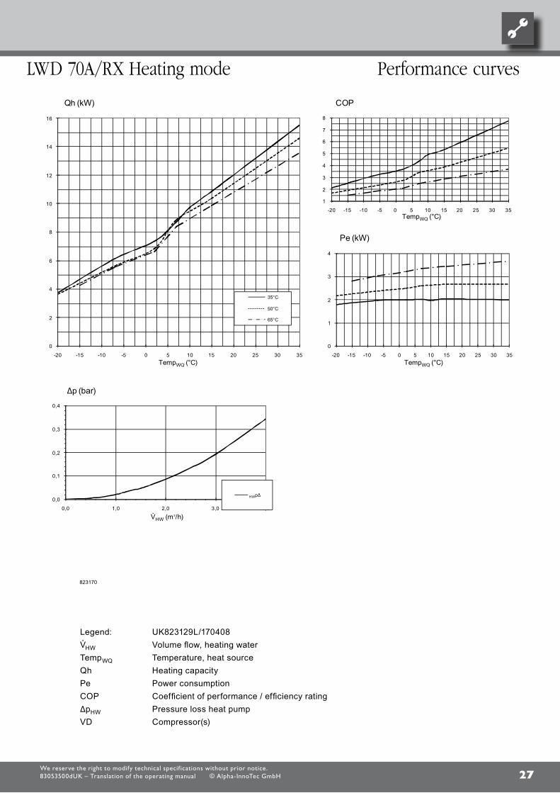
27
Legend: UK823129L/170408“” Volume flow, heating waterTemp„ Temperature, heat sourceQh Heating capacityPe Power consumptionCOP Coefficient of performance / efficiency rating∆p” Pressure loss heat pumpVD Compressor(s)
We reserve the right to modify technical specif ications without prior notice.83053500dUK – Translation of the operating manual © Alpha-InnoTec GmbH
LWD 70a/rX Heating mode Performance curves
Bezeichnung:
Seite: 1/2
Datei: 823170 Leistungs- Druckverlustkurven LWD 70ARX.xls
Zeichnungsnummer: 823170
Änd./Ä.M./Ersteller/Datum
- / PEP003-2012 / Mödder / 01.08.2012
Leistungs-DruckverlustkurvenLWD 70A/RX
Legende: DE823129L/170408
823170
“”
Druckverlust Wärmepumpe
Volumenstrom Heizwasser
Temperatur Wärmequelle
Heizleistung
Verdichter
Temp„
Qh
Pe
COP
∆p”
VD
Leistungsaufnahme
Coefficient of performance / Leistungszahl
0
2
4
6
8
10
12
14
16
-20 -15 -10 -5 0 5 10 15 20 25 30 35Temp„ (°C)
Qh (kW)
35°C
50°C
65°C
1
2
3
4
5
6
7
8
-20 -15 -10 -5 0 5 10 15 20 25 30 35Temp„ (°C)
COP
0
1
2
3
4
-20 -15 -10 -5 0 5 10 15 20 25 30 35Temp„ (°C)
Pe (kW)
0,0
0,1
0,2
0,3
0,4
0,0 1,0 2,0 3,0 4,0
“” (m³/h)
∆p (bar)
”p∆
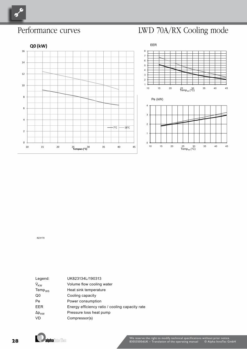
28
Legend: UK823134L/190313“© Volume flow cooling waterTemp¤ Heat sink temperatureQ0 Cooling capacityPe Power consumptionEER Energy efficiency ratio / cooling capacity rate∆p” Pressure loss heat pumpVD Compressor(s)
We reserve the right to modify technical specif ications without prior notice.83053500dUK – Translation of the operating manual © Alpha-InnoTec GmbH
Performance curves LWD 70a/rX Cooling mode
Bezeichnung:
Seite: 2/2
Zeichnungsnummer: 823170
Datei: 823170 Leistungs- Druckverlustkurven LWD 70ARX.xls
Änd./Ä.M./Ersteller/Datum Leistungs-Druckverlustkurven - / PEP003-2012 / Mödder / 01.08.2012 LWD 70ARX
EER Energy efficiency ratio / Kühlleistungszahl
Tempws Temperatur Wärmesenke
Q0 Kühlleistung
Pe Leistungsaufnahme
823170
0
2
4
6
8
10
12
14
16
10 15 20 25 30 35 40 45Tempws (°C)
Q0 (kW)
7°C 18°C
1
2
3
4
5
6
7
8
10 15 20 25 30 35 40 45Tempws (°C)
EER
0
1
2
3
4
10 15 20 25 30 35 40 45Tempws (°C)
Pe (kW)
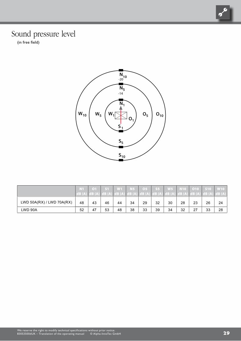
29
-14
LWD 50A / LWD 70A
-20
N1 dB (A)
O1 dB (A)
S1 dB (A)
W1 dB (A)
N5 dB (A)
O5 dB (A)
S5 dB (A)
W5 dB (A)
N10 dB (A)
O10 dB (A)
S10 dB (A)
W10 dB (A)
LWD 50A(RX) / LWD 70A(RX) 48 43 46 44 34 29 32 30 28 23 26 24
LWD 90A 52 47 53 48 38 33 39 34 32 27 33 28
We reserve the right to modify technical specif ications without prior notice.83053500dUK – Translation of the operating manual © Alpha-InnoTec GmbH
(in free field)
sound pressure level

30
DE819392
All dimensions in mm.
A Front view
B Side view
C-C Section (floor slab)
1 Heating water flow G1" DIN ISO 228 flat gasket.
2 Heating water return flow G1" DIN ISO 228 flat gasket.
3 Bleeder
4 Connection socket (in extra box) for condensate drain pipe DN40
5 Cables for power, control, BUS, length ~ 5m from unit
6 Penetration for flow & return and cables (in extra box)
We reserve the right to modify technical specif ications without prior notice.83053500dUK – Translation of the operating manual © Alpha-InnoTec GmbH
LWD 50a(rX) – LWD 70a(rX), LWD 90aDimensional drawings

31We reserve the right to modify technical specif ications without prior notice.83053500dUK – Translation of the operating manual © Alpha-InnoTec GmbH
LWD 50a(rX) – LWD 70a(rX), LWD 90a
Installation protection areas
0,93
mH
1
0,5m0,5m
2,3m
WP
SB
1
1
1
WP
SB
3,3m
2,45
m
1m1m
1m1m
WP SB
Legende: DE819401Technische Änderungen vorbehalten
WP WärmepumpeSB SchutzbereichH1 bis zum Boden1 Türen, Fenster, Lichtschächte, usw. ins Haus
Aufstellung Schutzbereich WärmepumpeWichtig:Die Wärmepumpe darf nur im Freien aufgestellt werden!Dabei ist das Gerät so zu positionieren, dass im Fall einer Leckage kein Kältemittel in das Gebäudegelangt oder auf irgendeine andere Weise Personen gefährden kann.
In dem Schutzbereich (siehe Abbildung), der sich zwischen der Geräteoberkante und dem Boden befindetdürfen sich keine Zündquellen, Fenster, Türen, Lüftungsöffnungen, Lichtschächte und der gleichenbefinden. Der Schutzbereich darf sich nicht auf Nachbargrundstücke oder öffentliche Verkehrsflächenerstrecken. Die Wanddurchführung durch die Gebäudehülle ist gasdicht auszuführen.
Abbildung: Sicherheitsabstände zur Wärmepumpe
AITgilt für:LWD 50A 100601LWD 70A 100602
Novelangilt für:LAD 5 103601LAD 7 103602
87654321
www.alpha-innotec.deD - 95359 Kasendorf
Industriestraße 3Alpha-InnoTec GmbH
1
1
Ers. d. Ers. f.
A
B
C
D
E
F F
E
D
C
B
A
4321
BenennungAufstellungshinweise Schutzbereich
819401 -Zust. Änderungstext
Datum10.6.2011
DMVon
Blatt
von
Werkstoff Gewicht
Maßstab 1:50 Det. Maßstab
Datum NameErstelltGepr.Norm.
9.6.2011 Markieton10.6.2011 Markieton
toleranzAllgemein-
DIN ISO 2768 -c
Oberflächen
ArtikelNr.
Schu
tzverm
erk IS
O 16
016 b
each
ten
Figure: Safe distances from heat pumpLegend: DE819401
WP Heat pumpSB Protection areaH1 to the floor1 Doors, windows, light wells, etc. into the building
Installation of heat pump protection area
Important: The heat pump may only be installed outdoors! The unit must be positioned so that in case of a leak the refrigerant cannot
get into the building or put people at risk in any other way.
In the protection area (see figure), which is located between the top edge of the unit and the floor, there must be no ignition sources, windows, doors, ventilation openings, light wells and similar. The protection area may not extend onto adjacent properties or public traffic areas. The wall penetration through the building envelope must be made gas-tight.

32
1320
930
>300
93
FS >
1800
A
1
2
X
C W
Y
V
UKG
OKB
4
53
510
445
200
430
400
FS >800 FS >800
FS >
1650
282
LR
LRO
FA
6
4
53
8
Legende: 819393-1cTechnische Änderungen vorbehalten.Alle Maße in mm.
V1 Variante 1A VorderansichtC DraufsichtV Detailansicht VerkleidungW Detailansicht WandbefestigungX Detailansicht Kondensatleitung innerhalb Gebäude Y Detailansicht Kondensatleitung außerhalb Gebäude
FA FertigaußenfassadeUKG Unterkante GerätOKB Oberkante BodenLRO Leerrohr KG DN 125, Øa 125, bauseits kürzenLR LuftrichtungFS Freiraum für Servicezwecke
1 Heizwasservorlauf (Zubehör)2 Heizwasserrücklauf (Zubehör)3 Kabeldurchführung4 Wanddurchführung (Zubehör)5 Kondensatablauf / Syphon (Aufstellungshinweise Kondensatablauf siehe Bedienungsanleitung)6 Konsole für Wandbefestigung (Zubehör)8 Verkleidung Wanddurchführung (Zubehör)
V1
87654321
www.alpha-innotec.deD - 95359 Kasendorf
Industriestraße 3Alpha-InnoTec GmbH
1
10
Ers. d. Ers. f.
A
B
C
D
E
F F
E
D
C
B
A
4321
BenennungAufstellungsplanLWD 50/70A
819393cba-Zust. Änderungstext
PEP 006/2011
PEP 003/2012ÄM 063/2012
PEP 006/2011
Datum10.6.201127.6.201120.6.20126.2.2013
DMVon
REDMDM Blatt
von
Werkstoff Gewicht
Maßstab 1:40 1:30Det. Maßstab
Datum NameErstelltGepr.Norm.
30.5.2011 Markieton11.2.2013 Markieton
toleranzAllgemein-
DIN ISO 2768 -c
Oberflächen
ArtikelNr.
Schu
tzverm
erk IS
O 16
016 b
each
ten
We reserve the right to modify technical specif ications without prior notice.83053500dUK – Translation of the operating manual © Alpha-InnoTec GmbH
Wall bracket installation plan WallfeedthRough
LWD 50a(rX) – LWD 70a(rX), LWD 90a
Legend: 819393-1cWe reserve the right to make changes without notice.All dimensions in mm.
„V1 Variant 1“A Front viewC Plan viewV Detail view of panellingW Detail view of wall mountingX Detail view of condensate pipe inside the building Y Detail view of condensate pipe outside the building
FA Finished outer façadeUKG Bottom edge of unitOKB Floor levelLRO Reserve conduit KG DN 125, Øa 125, shorten on siteLR Air directionFS Free space for service purposes
1 Heating water feed (accessory)2 Heating water return (accessory)3 Cable feedthrough4 Wall feedthrough (accessory)5 Condensate drain / siphon (see operating manual for condensate drain installation instructions)6 Bracket for wall mounting (accessory)
8 Wall feedthrough panelling (accessory)
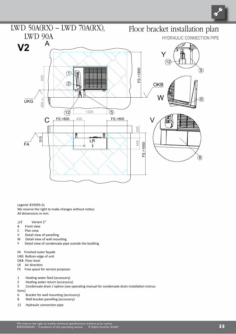
33We reserve the right to modify technical specif ications without prior notice.83053500dUK – Translation of the operating manual © Alpha-InnoTec GmbH
LWD 50a(rX) – LWD 70a(rX), LWD 90a
Floor bracket installation planHyDRaULiC COnnECTiOn PiPE
1320
930
300
±5
FS
>18
00
C
A
1
2
12 5
UKG
OKB
445
200
430 FS >800 FS >800
FS >
1650
510
LRFA
6W
Y12
5
V
8
Legende: 819393-2cTechnische Änderungen vorbehalten.Alle Maße in mm.
V2 Variante 2A VorderansichtC DraufsichtV Detailansicht VerkleidungW Detailansicht WandbefestigungY Detailansicht Kondensatleitung außerhalb Gebäude
FA FertigaußenfassadeUKG Unterkante GerätOKB Oberkante BodenLR LuftrichtungFS Freiraum für Servicezwecke
1 Heizwasservorlauf (Zubehör)2 Heizwasserrücklauf (Zubehör)5 Kondensatablauf / Syphon (Aufstellungshinweise Kondensatablauf siehe Bedienungsanleitung)6 Konsole für Wandbefestigung (Zubehör)8 Verkleidung Wandkonsole (Zubehör)12 Hydraulische Verbindungsleitung
V2
87654321
www.alpha-innotec.deD - 95359 Kasendorf
Industriestraße 3Alpha-InnoTec GmbH
Schutz
verme
rk nach
ISO 16
016 be
achten
2
10
Ers. d. Ers. f.
A
B
C
D
E
F F
E
D
C
B
A
4321
BenennungAufstellungsplanLWD 50/70A
819393cba-Zust. Änderungstext
PEP 006/2011
PEP 003/2012ÄM 063/2012
PEP 006/2011
Datum10.6.201127.6.201120.6.20126.2.2013
DMVon
REDMDM Blatt
von
Werkstoff Gewicht
Maßstab 1:40 1:30Det. Maßstab
Datum NameErstelltGepr.Norm.
30.5.2011 Markieton11.2.2013 Markieton
toleranzAllgemein-
DIN ISO 2768 -c
Oberflächen
ArtikelNr.
Legend: 819393-2cWe reserve the right to make changes without notice.All dimensions in mm.
„V2 Variant 2“A Front viewC Plan viewV Detail view of panellingW Detail view of wall mountingY Detail view of condensate pipe outside the building
FA Finished outer façadeUKG Bottom edge of unitOKB Floor levelLR Air directionFS Free space for service purposes
1 Heating water feed (accessory)2 Heating water return (accessory)5 Condensate drain / siphon (see operating manual for condensate drain installation instruc-tions)6 Bracket for wall mounting (accessory)8 Wall bracket panelling (accessory)
12 Hydraulic connection pipe
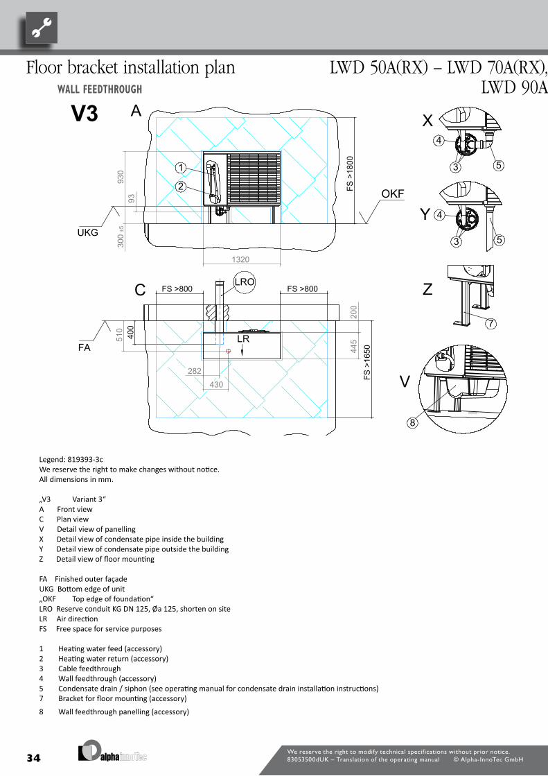
34We reserve the right to modify technical specif ications without prior notice.83053500dUK – Translation of the operating manual © Alpha-InnoTec GmbH
Floor bracket installation plan WallfeedthRough
LWD 50a(rX) – LWD 70a(rX), LWD 90a
930
1320
300
±5
93
FS >
1800
2
1
UKG
OKF
44551
0
200
430
400
FS >800 FS >800
FS >
1650
282
LR
LRO
FA
4
53
7
4
53
8
V3 A
C Z
Legende: 819393-2cTechnische Änderungen vorbehalten.Alle Maße in mm.
V3 Variante 3A VorderansichtC DraufsichtV Detailansicht VerkleidungX Detailansicht Kondensatleitung innerhalb Gebäude Y Detailansicht Kondensatleitung außerhalb GebäudeZ Detailansicht Bodenbefestigung
FA FertigaußenfassadeUKG Unterkante GerätOKF Oberkante FundamentLRO Leerrohr KG DN 125, Øa 125, bauseits kürzenLR LuftrichtungFS Freiraum für Servicezwecke
1 Heizwasservorlauf (Zubehör)2 Heizwasserrücklauf (Zubehör)3 Kabeldurchführung4 Wanddurchführung (Zubehör)5 Kondensatablauf / Syphon (Aufstellungshinweise Kondensatablauf siehe Bedienungsanleitung)7 Konsole für Bodenbefestigung (Zubehör)8 Verkleidung Wanddurchführung (Zubehör)
Y
X
V
87654321
www.alpha-innotec.deD - 95359 Kasendorf
Industriestraße 3Alpha-InnoTec GmbH
Schutz
verme
rk nach
ISO 16
016 be
achten
3
10
Ers. d. Ers. f.
A
B
C
D
E
F F
E
D
C
B
A
4321
BenennungAufstellungsplanLWD 50/70A
819393cba-Zust. Änderungstext
PEP 006/2011
PEP 003/2012ÄM 063/2012
PEP 006/2011
Datum10.6.201127.6.201120.6.20126.2.2013
DMVon
REDMDM Blatt
von
Werkstoff Gewicht
Maßstab 1:40 1:30Det. Maßstab
Datum NameErstelltGepr.Norm.
30.5.2011 Markieton11.2.2013 Markieton
toleranzAllgemein-
DIN ISO 2768 -c
Oberflächen
ArtikelNr.
Legend: 819393-3cWe reserve the right to make changes without notice.All dimensions in mm.
„V3 Variant 3“A Front viewC Plan viewV Detail view of panellingX Detail view of condensate pipe inside the building Y Detail view of condensate pipe outside the buildingZ Detail view of floor mounting
FA Finished outer façadeUKG Bottom edge of unit„OKF Top edge of foundation“LRO Reserve conduit KG DN 125, Øa 125, shorten on siteLR Air directionFS Free space for service purposes
1 Heating water feed (accessory)2 Heating water return (accessory)3 Cable feedthrough4 Wall feedthrough (accessory)5 Condensate drain / siphon (see operating manual for condensate drain installation instructions)7 Bracket for floor mounting (accessory)
8 Wall feedthrough panelling (accessory)

35
930
1320
300
±5
FS >
1800
2
1
12 5
UKG
OKF
445
200
FS >800 FS >800
FS >
1650
510
430
LRFA
5
12
7
8
Legende: 819393-4cTechnische Änderungen vorbehalten.Alle Maße in mm.
V4 Variante 4A VorderansichtC DraufsichtV Detailansicht VerkleidungY Detailansicht Kondensatleitung außerhalb GebäudeZ Detailansicht Bodenbefestigung
FA FertigaußenfassadeUKG Unterkante GerätOKF Oberkante FundamentLR LuftrichtungFS Freiraum für Servicezwecke
1 Heizwasservorlauf (Zubehör)2 Heizwasserrücklauf (Zubehör)5 Kondensatablauf / Syphon (Aufstellungshinweise Kondensatablauf siehe Bedienungsanleitung)7 Konsole für Bodenbefestigung (Zubehör)8 Verkleidung Bodenkonsole (Zubehör)12 Hydraulische Verbindungsleitung
V4Y
Z
A
CV
87654321
www.alpha-innotec.deD - 95359 Kasendorf
Industriestraße 3Alpha-InnoTec GmbH
Schutz
verme
rk nach
ISO 16
016 be
achten
4
10
Ers. d. Ers. f.
A
B
C
D
E
F F
E
D
C
B
A
4321
BenennungAufstellungsplanLWD 50/70A
819393cba-Zust. Änderungstext
PEP 006/2011
PEP 003/2012ÄM 063/2012
PEP 006/2011
Datum10.6.201127.6.201120.6.20126.2.2013
DMVon
REDMDM Blatt
von
Werkstoff Gewicht
Maßstab 1:40 1:30Det. Maßstab
Datum NameErstelltGepr.Norm.
30.5.2011 Markieton11.2.2013 Markieton
toleranzAllgemein-
DIN ISO 2768 -c
Oberflächen
ArtikelNr.
We reserve the right to modify technical specif ications without prior notice.83053500dUK – Translation of the operating manual © Alpha-InnoTec GmbH
LWD 50a(rX) – LWD 70a(rX), LWD 90a
Floor bracket installation planHyDRaULiC COnnECTiOn PiPE
Legend: 819393-4cWe reserve the right to make changes without notice.All dimensions in mm.
V4 Variant 4“A Front viewC Plan viewV Detail view of panellingY Detail view of condensate pipe outside the buildingZ Detail view of floor mounting“
FA Finished outer façadeUKG Bottom edge of unitOKF Top edge of foundation“LR Air directionFS Free space for service purposes
1 Heating water feed (accessory)2 Heating water return (accessory)5 Condensate drain / siphon (see operating manual for condensate drain installation instructions)7 Bracket for floor mounting (accessory)8 Floor bracket panelling (accessory)
12 Hydraulic connection pipe
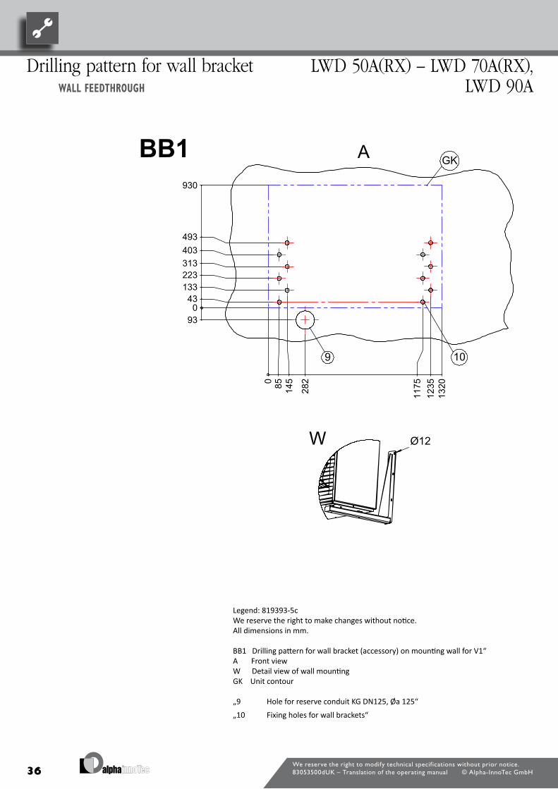
36We reserve the right to modify technical specif ications without prior notice.83053500dUK – Translation of the operating manual © Alpha-InnoTec GmbH
Drilling pattern for wall bracket WallfeedthRough
LWD 50a(rX) – LWD 70a(rX), LWD 90a
0 43
93
133 223 313 403 493
0
85
145
282
117
5 1
235
930
132
0
9 10
GK
Ø12W
BB1
Legende: 819393-5cTechnische Änderungen vorbehalten.Alle Maße in mm.
BB1 Bohrbild für Wandkonsole (Zubehör) an Befestigungswand zu V1A VorderansichtW Detailansicht WandbefestigungGK Gerätekontur
9 Bohrung für Leerrohr KG DN125, Øa 12510 Befestigungsbohrungen für Wandkonsolen
A
87654321
www.alpha-innotec.deD - 95359 Kasendorf
Industriestraße 3Alpha-InnoTec GmbH
Schutz
verme
rk nach
ISO 16
016 be
achten
5
10
Ers. d. Ers. f.
A
B
C
D
E
F F
E
D
C
B
A
4321
BenennungAufstellungsplanLWD 50/70A
819393cba-Zust. Änderungstext
PEP 006/2011
PEP 003/2012ÄM 063/2012
PEP 006/2011
Datum10.6.201127.6.201120.6.20126.2.2013
DMVon
REDMDM Blatt
von
Werkstoff Gewicht
Maßstab 1:40 1:30Det. Maßstab
Datum NameErstelltGepr.Norm.
30.5.2011 Markieton11.2.2013 Markieton
toleranzAllgemein-
DIN ISO 2768 -c
Oberflächen
ArtikelNr.
Legend: 819393-5cWe reserve the right to make changes without notice.All dimensions in mm.
BB1 Drilling pattern for wall bracket (accessory) on mounting wall for V1“A Front viewW Detail view of wall mountingGK Unit contour
„9 Hole for reserve conduit KG DN125, Øa 125“
„10 Fixing holes for wall brackets“
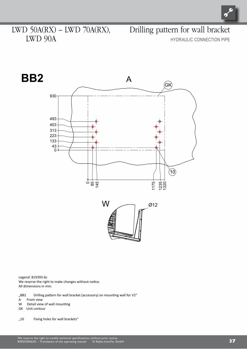
37We reserve the right to modify technical specif ications without prior notice.83053500dUK – Translation of the operating manual © Alpha-InnoTec GmbH
LWD 50a(rX) – LWD 70a(rX), LWD 90a
Drilling pattern for wall bracketHyDRaULiC COnnECTiOn PiPE
0 43
133 223 313 403 493
0
85
145
117
5
123
5
930
132
0
10
GK
Ø12W
Legende: 819393-6cTechnische Änderungen vorbehalten.Alle Maße in mm.
BB2 Bohrbild für Wandkonsole (Zubehör) an Befestigungswand zu V2A VorderansichtW Detailansicht WandbefestigungGK Gerätekontur
10 Befestigungsbohrungen für Wandkonsolen
ABB2
87654321
www.alpha-innotec.deD - 95359 Kasendorf
Industriestraße 3Alpha-InnoTec GmbH
Schutz
verme
rk nach
ISO 16
016 be
achten
6
10
Ers. d. Ers. f.
A
B
C
D
E
F F
E
D
C
B
A
4321
BenennungAufstellungsplanLWD 50/70A
819393cba-Zust. Änderungstext
PEP 006/2011
PEP 003/2012ÄM 063/2012
PEP 006/2011
Datum10.6.201127.6.201120.6.20126.2.2013
DMVon
REDMDM Blatt
von
Werkstoff Gewicht
Maßstab 1:40 1:30Det. Maßstab
Datum NameErstelltGepr.Norm.
30.5.2011 Markieton11.2.2013 Markieton
toleranzAllgemein-
DIN ISO 2768 -c
Oberflächen
ArtikelNr.
Legend: 819393-6cWe reserve the right to make changes without notice.All dimensions in mm.
„BB2 Drilling pattern for wall bracket (accessory) on mounting wall for V2“A Front viewW Detail view of wall mountingGK Unit contour
„10 Fixing holes for wall brackets“
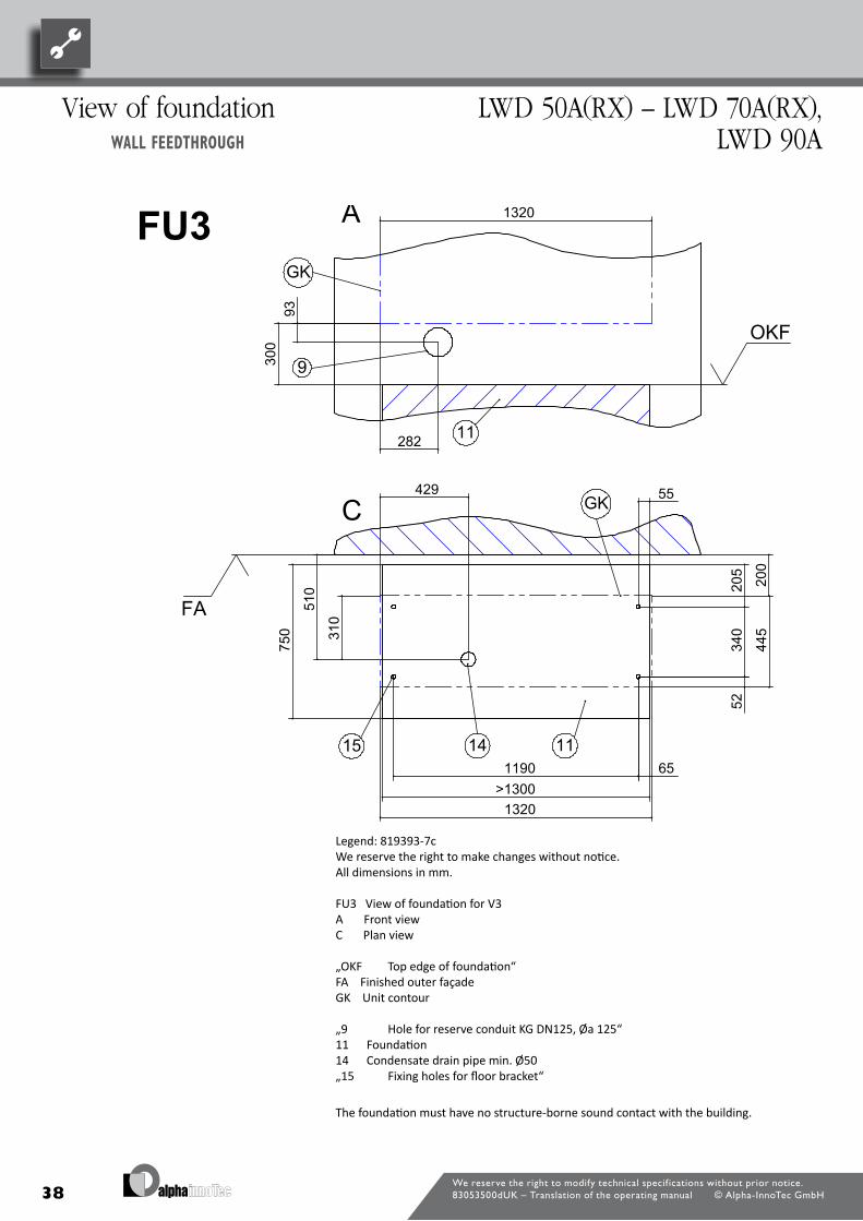
38We reserve the right to modify technical specif ications without prior notice.83053500dUK – Translation of the operating manual © Alpha-InnoTec GmbH
View of foundation WallfeedthRough
LWD 50a(rX) – LWD 70a(rX), LWD 90a
93
282
300
1320
9
GK
OKF
340
>1300 1190
750
55
205
445
52
200
65
1320
510
310
429
15
GK
14 11
11
FA
FU3
Legende: 819393-7cTechnische Änderungen vorbehalten.Alle Maße in mm.
FU3 Ansicht Fundament zu V3A VorderansichtC Draufsicht
OKF Oberkante FundamentFA FertigaußenfassadeGK Gerätekontur
9 Bohrung für Leerrohr KG DN125, Øa 12511 Fundament14 Kondensatablaufrohr min. Ø5015 Befestigungsbohrungen für Bodenkonsole
Das Fundament darf keinen Körperschallkontakt zum Gebäude haben.
A
C
87654321
www.alpha-innotec.deD - 95359 Kasendorf
Industriestraße 3Alpha-InnoTec GmbH
Schutz
verme
rk nach
ISO 16
016 be
achten
7
10
Ers. d. Ers. f.
A
B
C
D
E
F F
E
D
C
B
A
4321
BenennungAufstellungsplanLWD 50/70A
819393cba-Zust. Änderungstext
PEP 006/2011
PEP 003/2012ÄM 063/2012
PEP 006/2011
Datum10.6.201127.6.201120.6.20126.2.2013
DMVon
REDMDM Blatt
von
Werkstoff Gewicht
Maßstab 1:40 1:30Det. Maßstab
Datum NameErstelltGepr.Norm.
30.5.2011 Markieton11.2.2013 Markieton
toleranzAllgemein-
DIN ISO 2768 -c
Oberflächen
ArtikelNr.
Legend: 819393-7cWe reserve the right to make changes without notice.All dimensions in mm.
FU3 View of foundation for V3A Front viewC Plan view
„OKF Top edge of foundation“FA Finished outer façadeGK Unit contour
„9 Hole for reserve conduit KG DN125, Øa 125“11 Foundation14 Condensate drain pipe min. Ø50„15 Fixing holes for floor bracket“
The foundation must have no structure-borne sound contact with the building.

39We reserve the right to modify technical specif ications without prior notice.83053500dUK – Translation of the operating manual © Alpha-InnoTec GmbH
LWD 50a(rX) – LWD 70a(rX), LWD 90a
View of foundationHyDRaULiC COnnECTiOn PiPE
Ø12
1190 >1300
340
750
170
2
20
330 140
120
280
55
205
105
100 5
2
1320
445
65
430
310
X
11
12 14 15GK
X (1 : 5)
16
13
17
~10
0 14
12
13
11OKFFU4
Legende: 819393-8cTechnische Änderungen vorbehalten.Alle Maße in mm.
FU4 Ansicht Fundament zu V4A VorderansichtC DraufsichtX Detailansicht X
11 Fundament12 Hydraulische Verbindungsleitung13 Leerrohr DN150 (bauseits)14 Kondensatablaufrohr min. Ø50
C
Z Detailansicht BodenbefestigungOKF Oberkante FundamentGK Gerätekontur
15 Befestigungsbohrungen für Bodenkonsole16 Leerrohr für Bus-Kabel17 Leerrohr für Elektrokabel18 Heizwasser Vor- und Rücklaufleitung
A
Z
Das Fundament darf keinen Körperschallkontakt zum Gebäude haben.
18
87654321
www.alpha-innotec.deD - 95359 Kasendorf
Industriestraße 3Alpha-InnoTec GmbH
Schutz
verme
rk nach
ISO 16
016 be
achten
8
10
Ers. d. Ers. f.
A
B
C
D
E
F F
E
D
C
B
A
4321
BenennungAufstellungsplanLWD 50/70A
819393cba-Zust. Änderungstext
PEP 006/2011
PEP 003/2012ÄM 063/2012
PEP 006/2011
Datum10.6.201127.6.201120.6.20126.2.2013
DMVon
REDMDM Blatt
von
Werkstoff Gewicht
Maßstab 1:40 1:30Det. Maßstab
Datum NameErstelltGepr.Norm.
30.5.2011 Markieton11.2.2013 Markieton
toleranzAllgemein-
DIN ISO 2768 -c
Oberflächen
ArtikelNr.
Legend: 819393-8cWe reserve the right to make changes without notice.All dimensions in mm.
FU4 View of foundation for V4A Front viewC Plan viewX Detail view X
11 Foundation12 Hydraulic connection pipe13 Reserve conduit DN150 (on site)14 Condensate drain pipe min. Ø50
Z Detail view of floor mounting“OKF Top edge of foundationGK Unit contour
„15 Fixing holes for floor bracket“16 Reserve conduit for bus cable17 Reserve conduit for electric cable18 Heating water feed and return pipeThe foundation must have no structure-borne sound contact
with the building.

40We reserve the right to modify technical specif ications without prior notice.83053500dUK – Translation of the operating manual © Alpha-InnoTec GmbH
>300
0
>3000
C
LRFA
FW2
Legende: 819393-10cTechnische Änderungen vorbehalten.Alle Maße in mm.
FW2 Funktionsnotwendige MindestabständeC Draufsicht
FA FertigaußenfassadeLR Luftrichtung
Mindestabstände
87654321
www.alpha-innotec.deD - 95359 Kasendorf
Industriestraße 3Alpha-InnoTec GmbH
Schutz
verme
rk nach
ISO 16
016 be
achten
10
10
Ers. d. Ers. f.
A
B
C
D
E
F F
E
D
C
B
A
4321
BenennungAufstellungsplanLWD 50/70A
819393cba-Zust. Änderungstext
PEP 006/2011
PEP 003/2012ÄM 063/2012
PEP 006/2011
Datum10.6.201127.6.201120.6.20126.2.2013
DMVon
REDMDM Blatt
von
Werkstoff Gewicht
Maßstab 1:40 1:30Det. Maßstab
Datum NameErstelltGepr.Norm.
30.5.2011 Markieton11.2.2013 Markieton
toleranzAllgemein-
DIN ISO 2768 -c
Oberflächen
ArtikelNr.
Legend: 819393-10cWe reserve the right to make changes without notice.All dimensions in mm.
FW2 Functionally necessary minimum spacingsC Plan view
FA Finished outer façadeLR Air direction
Minimum clearances
minimum clearances LWD 50a(rX) – LWD 70a(rX), LWD 90a

41We reserve the right to modify technical specif ications without prior notice.83053500dUK – Translation of the operating manual © Alpha-InnoTec GmbH
0,9m
KS
3
0,9m
1b
3
1c
3
1a
Legende: 819400-1Technische Änderungen vorbehalten.
Aufstellungshinweise für Anschluß der Kondensatleitung außerhalb des Gebäudes.KS Kiesschicht zur Aufnahme von bis zu 50l Kondenswasser pro Tag als Pufferzone zum versickern.3 Kondensatablaufrohr DN 40
Wichtig: Beim direkten Einleiten des Kondenswassers in die Erde (Abbildung 1a), muss das Kondensatablaufrohr (3) zwischen Boden und Wärmepumpe isoliert werden.
Wichtig: Bei direktem Einleiten des Kondenswassers in eine Abwasser- oder Regenwasserleitung muss ein Syphon gesetzt werden (Abbildung 1b). Es muss ein oberhalb des Bodenreichs gedämmtes und senkrecht verlegtes Kunststoffrohr verwendet werden. Weiterhin dürfen im Abflussrohr keine Rückschlagklappen oder ähnliches installiert sein. Das Kondensatablaufrohr muss so angeschlossen werden, dass das Kondensat frei in die Hauptleitung einfließen kann. Wird das Kondensat in Drainagen oder in die Kanalisation abgeleitet, ist auf eine Verlegung mit einem Gefälle zu achten.
In allen Fällen (Abbildung 1a und Abbildung 1b) muss gewährleistet sein,dass das Kondenswasser frostfrei abgeführt wird.
87654321
www.alpha-innotec.deD - 95359 Kasendorf
Industriestraße 3Alpha-InnoTec GmbH
1
2
Ers. d. Ers. f.
A
B
C
D
E
F F
E
D
C
B
A
4321
BenennungAufstellungshinweiseKondensatablauf
819400 -Zust. Änderungstext
Datum10.6.2011
DMVon
Blatt
von
Werkstoff Gewicht
Maßstab 1:40 Det. Maßstab
Datum NameErstelltGepr.Norm.
9.6.2011 Markieton10.6.2011 Markieton
toleranzAllgemein-
DIN ISO 2768 -c
Oberflächen
ArtikelNr.
Schu
tzverm
erk IS
O 16
016 b
each
ten
Outside connection of condensate pipe
LWD 50a(rX) – LWD 70a(rX), LWD 90a
Legend: 819400-1
Installation instructions for connecting the condensate pipe outside the building
KS Gravel layer for absorbing up to 50l condensation water per day
as buffer zone for percolating.
3 Condensate drain pipe DN 40
Important: If the condensation water is discharged directly into the ground (figure 1a)
the condensate drain pipe (3) must be insulated between the ground and the heat pump.
Important: If the condensation water is discharged directly into a wastewater or
rainwater pipe a syphon must be used (figure 1b).
A plastic pipe, laid vertically and insulated above the ground, must be
used. Further, do not install any non-return valves or similar in the drain pipe.
The condensate drain pipe must be connected so that
the condensate can flow freely into the main pipe. If the condensate is
discharged into filter drains or the sewers, ensure the pipes are laid with a gradient.
In all cases (figure 1a and figure 1b) ensure that
the condensation water is discharged in a frost-free zone.

42We reserve the right to modify technical specif ications without prior notice.83053500dUK – Translation of the operating manual © Alpha-InnoTec GmbH
2a 2b
Legende: 819400-2Technische Änerungen vorbehalten.
Aufstellungshinweise für Anschluß der Kondensatleitung innerhalb des Gebäudes.
Wichtig: Beim Anschluss der Kondensatleitung innerhalb eines Gebäudes muss ein Syphon eingebaut werden, der mit dem Abflussrohr gasdicht abschließt (siehe Abbildung 2a). An der Kondensatabflussleitung der Wärmepumpe dürfen keine zusätzlichen Abflussleitungen angeschlossen werden. Die Abflussleitung in Richtung Kanalisation muss frei sein. D.h. nach der Anschlussleitung der Wärmepumpe darf weder eine Rückschlagklappe noch ein Syphon eingebaut werden.
In allen Fällen (Abbildung 2a) muss gewährleistet sein, dass das Kondenswasser frostfrei abgeführt wird.
87654321
www.alpha-innotec.deD - 95359 Kasendorf
Industriestraße 3Alpha-InnoTec GmbH
Schutz
verme
rk nach
DIN 3
4 beac
hten
2
2
Ers. d. Ers. f.
A
B
C
D
E
F F
E
D
C
B
A
4321
BenennungAufstellungshinweiseKondensatablauf
819400 -Zust. Änderungstext
Datum10.6.2011
DMVon
Blatt
von
Werkstoff Gewicht
Maßstab 1:40 Det. Maßstab
Datum NameErstelltGepr.Norm.
9.6.2011 Markieton10.6.2011 Markieton
toleranzAllgemein-
DIN ISO 2768 -c
Oberflächen
ArtikelNr.
LWD 50a(rX) – LWD 70a(rX), LWD 90a
Inside connection of condensate pipe
Legend: 819400-2
Installation instructions for connecting the condensate pipe inside the building
.
Important: When connecting the condensate pipe inside the building, a syphon
must be installed, which is connected gas-tight to the drain pipe (see figure 2a).
Do not connect any additional drain pipes to the condensate drain pipe of the heat pump.
The drain pipe must be free in the direction of the sewer.
I.e. ensure that downstream of the heat pump connection pipe there are no
non-return valves or syphons.
In all cases (figure 2a) it must be ensured that the condensation water is discharged in a frost-free zone
.
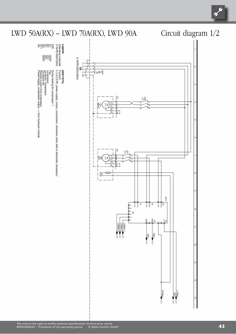
43
L1L2
L3N
PE
N
-X10
12
-Q3
/2.5
34
M3
U1
V1
W1
PE
-G1
VE
NT 56
12
-Q1
/2.4
34
M3
T1
T2
T3
PE
-M1
VD
1
56
-E20
L1In
L1out
L2In
L2out
L3In
L3out
HS
o
HS
i
X1
X2
X3
X4
X5
X6
32
13
21 L1
-Q11
LIN
SA
-1/2.1
LIN
SA
-2/2.1
LIN
SA
-3/2.1
HS
o/2.1
HS
i/2.1
L R
eg
/2.1E
20/2.1
N R
eg
/2.1
PE
VD
1Q
1con
tactor, compresso
r
X8
gr
Leg
en
d:
3~N/P
E/400V
/50Hz
sw
Function
Sum
p heating for com
pressor 1E
20
Pow
er supply, compressor output -->
from hydraulic m
odule
Q11
X8
VE
NT
M1
VD
1
L1,L2,L3,PE
; power supply, output, com
pressor; clockwise rotary field is absolutely nece
ssary!
-G1
Q3
1P
E
Starting current lim
it compressor
Operating m
aterials
34
2
VE
NT
1
3~N
/PE
/400V/50H
z
compressor
3
G1
UK
81
7377a
-M1
br2
Contactor fan
Fan
LWD
50-70 / LWD
50-70 Reversibel
817377
Achim
Pfleg
er1
7.05.2
011
aP
EP
003/2012
12
34
56
78
910
1112
1314
1516
12
34
56
78
910
1112
1314
1516 1
/2
1
16.0
2.2
012
PE
P 006/2011
10X
605 - 10X
606
;
-A
chim P
fleger
10X601 - 1
0X6
02;
Blatt-N
r.
Zusta
ndÄ
nde
rung
Bea
rb.
Datu
mN
ame
Bl vo
n An
z
Datu
m
We reserve the right to modify technical specif ications without prior notice.83053500dUK – Translation of the operating manual © Alpha-InnoTec GmbH
LWD 50a(rX) – LWD 70a(rX), LWD 90a Circuit diagram 1/2

44
L R
eg/1.15
E20
/1.15
HS
i/1.12
HS
o/1.12
LIN
SA
-3/1.11
LIN
SA
-2/1.11
LIN
SA
-1/1.11
N R
eg/1.15
PE
-X1
PE
-X10
NN
PE
NL LL
P+
-
b2c4a1
-F1
HD
P
DI1
-X2
A1
A2
-Q1VD
1
OUT1
N
-K21
OUT3
OUT4
OUT5
A1
A2
-Q3
VE
NT
L..
-X4
L..
L..
B/
-X6
A
Green
Yellow
white
Brown
-K22 A
/B
ϑ
NT1
-X7
-R1
TS
G1
GND
ϑ
NT2
-R2
TV
D
GND
ϑ
NT3
-R3
TW
E
GND
ϑ
NT4
-R4
TH
G
GND
NT9
-R9
CW
GND
ϑ
NT5
-R5
TS
G2
GND
GND
-X8
IP
12
-B1
0H
D
AIN1
GND
IP
12
-B11
ND
AIN2
6-X
115
43
2
32
1P
E
1
12
/1.43
4/1.4
56
/1.4
12
/1.73
4/1.7
56
/1.7
1
R3
Suction sensor, com
pressor
K22
Operating m
aterials
Controller board; A
ttention: I-max =
6A
/230VA
C
ND
VD
1
2
L,N,P
E; pow
er supply, controller
TH
G
Function
K20
Leg
en
d:
r t
contactor, com
pressor
HD
P
Control voltage -->
From
hydraulic m
odule
Heat source
input sensor
Contactor fan
Electro
nic expansion valve
UK
81
7377a
Q3
sw
X10
bl
Low pressure sensor
B11
Q1
1~N
/PE
/230V/50H
z
R1
Defrosting valve
X10
TV
D
Hot gas sensor
1
TS
G2
2
Coder resista
nce 5KW
10kOhm
; 7KW
10,5kO
hm; 5K
Wrev. 14,7kO
hm; 7K
Wrev. 15,4kO
hm
1
LIN
CW
2
blbrS
uction sensor, evaporator
High-pressu
re switch
R5
R9
TW
E
F1
-K20
VE
NT
1~N/P
E/230V
/50HzSum
p heating sensor
-F1
B10
R4
R2
23
0V
AC
TS
G1
3
High-pressu
re sensor
K21
GN
D/LIN
/12V
HD
LWD
50-70 / LWD
50-70 Reversibel
817377
Achim
Pfleg
er2
7.09.2
010
aP
EP
003/2012
12
34
56
78
910
1112
1314
1516
12
34
56
78
910
1112
1314
1516 2
/2
2
16.0
2.2
012
PE
P 006/2011
10X
605 - 10X
606
;
-A
chim P
fleger
10X601 - 1
0X6
02;
Blatt-N
r.
Zusta
ndÄ
nde
rung
Bea
rb.
Datu
mN
ame
Bl vo
n An
z
Datu
m
We reserve the right to modify technical specif ications without prior notice.83053500dUK – Translation of the operating manual © Alpha-InnoTec GmbH
Circuit diagram 2/2 LWD 50a(rX) – LWD 70a(rX), LWD 90a
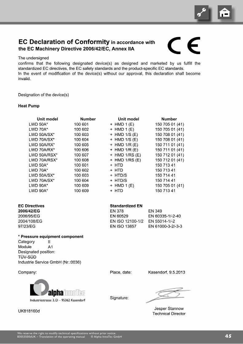
45
EC Declaration of Conformity in accordance ithEC Declaration of Conformity in accordance withythe EC Machinery Directive 2006/42/EC Annex IIAthe EC Machinery Directive 2006/42/EC, Annex IIAy ,
The undersignedfi th t th f ll i d i t d d i ( ) d i d d k t d b f lfill th
The undersignedconfirms that the following designated device(s) as designed and marketed by us fulfill theg g ( ) g ystandardized EC directives the EC safety standards and the product-specific EC standardsstandardized EC directives, the EC safety standards and the product-specific EC standards.In the event of modification of the device(s) without our approval this declaration shall becomeIn the event of modification of the device(s) without our approval, this declaration shall become( ) ppinvalid.invalid.
D i ti f th d i ( )Designation of the device(s)g ( )
H t PHeat PumpHeat Pump
NumberUnit modelNumberUnit model NumberUnit modelNumberUnit model100 601 + HMD 1 (E)LWD 50A* 150 705 01 (41)100 601100 602
+ HMD 1 (E) + HMD 1 (E)
LWD 50ALWD 70A*
150 705 01 (41)150 705 01 (41)100 602 + HMD 1 (E) LWD 70A* 150 705 01 (41)
100 603( )
+ HMD 1/S (E)LWD 50A/SX*( )
150 708 01 (41)100 603100 604
+ HMD 1/S (E) + HMD 1/S (E)
LWD 50A/SXLWD 70A/SX*
150 708 01 (41)150 708 01 (41)100 604 + HMD 1/S (E) LWD 70A/SX* 150 708 01 (41)
100 605 + HMD 1/R (E) LWD 50A/RX* 150 711 01 (41)100 605100 606
+ HMD 1/R (E) + HMD 1/R (E)
LWD 50A/RXLWD 70A/RX*
150 711 01 (41)150 711 01 (41)100 606 + HMD 1/R (E) LWD 70A/RX* 150 711 01 (41)
100 607 + HMD 1/RS (E) 150 712 01 (41)LWD 50A/RSX* 100 607+ HMD 1/RS (E)
HMD 1/RS (E) 150 712 01 (41)150 712 01 (41)
LWD 50A/RSXLWD 70A/RSX* 100 608
150 713 41+ HMD 1/RS (E)
HTD150 712 01 (41)LWD 70A/RSX*
LWD 50A*100 608100 601 150 713 41+ HTDLWD 50A* 100 601
LWD 70A*150 713 41 HTDLWD 50A 100 601
+ HTD 150 713 41100 602LWD 50A/SX*LWD 70A + HTD 150 713 41
150 714 41HTD/S100 602100 603LWD 50A/SX* 150 714 41+ HTD/S 100 603
LWD 70A/SX* 100 604 150 714 41+ HTD/SLWD 70A/SXLWD 90A*
100 604100 609 150 705 01 (41)+ HMD 1 (E)
150 714 41+ HTD/S LWD 90A* 100 609 150 705 01 (41)+ HMD 1 (E) LWD 90A* 100 609 150 713 41
( )( )+ HTDLWD 90A 100 609 150 713 41+ HTD
EC Directives Standardized ENEC Directives Standardized ENEN 3782006/42/EG EN 349EN 3782006/42/EG EN 349
2006/95/EG EN 60529 EN 60335 1/ 2 402004/108/EG EN ISO 12100 1/2 EN 55014 1/ 22006/95/EG EN 60529 EN 60335-1/-2-402004/108/EG EN ISO 12100-1/2 EN 55014-1/-2
EN 61000-3-2/-3-32004/108/EG EN ISO 12100 1/2 EN 55014 1/ 297/23/EG EN ISO 13857 EN 61000-3-2/-3-397/23/EG EN ISO 13857
* Pressure equipment componentII
Pressure equipment componentC t IICategory
A1Moduleg y
A1ModuleDesignated position:Designated position:g pTÜV-SÜDTÜV-SÜDIndustrie Service GmbH (Nr :0036)Industrie Service GmbH (Nr.:0036)( )
Company: Place date: Kasendorf 9 5 2013Company: Place, date: Kasendorf, 9.5.2013
Si tSignature:g
J StUK818160d Jesper StannowUK818160d Jesper StannowTechnical DirectorTechnical Director
We reserve the right to modify technical specif ications without prior notice.83053500dUK – Translation of the operating manual © Alpha-InnoTec GmbH

46We reserve the right to modify technical specif ications without prior notice.83053500dUK – Translation of the operating manual © Alpha-InnoTec GmbH
Customer serviceaddRessesfoRseRviCe
for a current list and additional partners of the manufacturer, please visit www.alpha.innotec.com.
at Alpha-InnoTec Österreich Eco-Wp Wärmepumpenhandelsges. m.b.H Währingerstr. 26 1090 Wien Tel.: +43 (0) 800 205 852fax: +43 (0) 800 205 [email protected] www.alpha-innotec.at Be/LuX NATHAN Import/Export N.v.-S.A. lozenberg 4 1932 Zaventem Tel.: +32 (0) 27 21 15 70fax: +32 (0) 27 25 35 [email protected] www.nathan.be Br THERmAcqUA Av. República Argentina 3021 conj. 14 piso l cEp 80610-260 portao curtiba pR Tel.: +55 (0) 41 301 566 59fax: +55 (0) 41 301 566 [email protected] www.thermacqua.com.br CH ait-schweiz AG Industriepark 6246 Altishofen Tel.: +41 (0) 62 74820 00fax: +41 (0) 62 74820 [email protected] www.alpha-innotec.ch Suisse romande ait-schweiz AG ch. de la venoge 7 1025 St. Sulpice Tel.: +41 (0) 21 661 31 43fax: +41 (0) 21 661 31 [email protected] www.alpha-innotec.ch
Ticino ait-schweiz AG via alla Torre 2 6850 mendriso Tel.: +41 (0) 91 646 08 81fax: +41 (0) 91 646 09 [email protected] www.alpha-innotec.ch CZ / sK Tepelná cerpadla AIT s.r.o. nám. Republiky 15 614 00 brno Tel.: +420 (0) 545 21 40 03fax: +420 (0) 545 24 20 [email protected] www.alpha-innotec.cz De Alpha-InnoTec GmbH Industriestrasse 3 95359 Kasendorf Tel.: +49 (0) 9228 99060fax: +49 (0) 9228 [email protected] www.alpha-innotec.com DK ASAp Energy Tinggaardvej 7 6400 Sønderborg Tel.: +45 (0) 74 4304 80fax: +45 (0) 74 4304 [email protected] www.asap.dk ee AIT-Nord oÜ Artelli 10 A 10621 Tallinn Tel.: +372 (0) 658 08 70fax: +372 (0) 650 18 [email protected] www.ait-nord.ee
FI oy callidus Ab Hiekkakiventie 1 00710 Helsinki Tel.: +358 9 374 751fax: +358 9 374 755 [email protected] www.callidus.fi Fr ait-france 10 rue des moines 67500 Haguenau Tel.: +33 (0) 3 880 624 10fax: +33 (0) 3 880 624 [email protected] www.alpha-innotec.fr Hu Thermo Kft. Krisztina körút 27 1122 budapest Tel.: +36 (0) 135 620 46fax: +36 (0) 121 428 [email protected] www.alpha-innotec.hu Ie origen office Naas Road muirfield drive, Naas Road, dublin 12 Tel.: +353 (0) 141 919 19fax: +353 (0) 145 848 [email protected] www.origen.ie It forti consult SAS Zona Artigianale Nord, 8 39040 oRA - bZ Tel.: +39 04 71 811 460fax: +39 04 71 811 [email protected] www.alpha-innotec.it

47We reserve the right to modify technical specif ications without prior notice.83053500dUK – Translation of the operating manual © Alpha-InnoTec GmbH
Lt/Lv UAb TENKo baltic basanaviciaus g. 45 03109 vilnius Tel.: +370 526 435 82fax: +370 526 435 [email protected] www.tenko.lt nL NATHAN Import/Export b.v. Impact 73 6921 RZ duiven Tel.: +31 (0) 26 445 98 45fax: +31 (0) 26 445 93 [email protected] www.nathan.nl no Alpha-InnoTec Norge AS Gamle forusveien 51b 4033 Stavanger Tel.: +47 (0) 51 6605 95fax: +47 (0) 51 6605 [email protected] www.alpha-innotec.no pL Hydro-Tech ul. Zakładowa 4d 62-510 Konin Tel.: +48 (0) 63 245 34 79fax: +48 (0) 63 242 37 [email protected] www.hydro-tech.pl pt GudEnergy Energias Renováveis, lda. Av. o Século, 21 r/c d.to 2135-231 Samora correia Tel.: +351 (0) 263 655 439fax: +351 (0) 263 655 [email protected] www.gudenergy.pt
se bjärneroth Teknik Evas väg 5 280 64 Glimåkra Tel.: +46 (0) 708 420 544fax: +46 (0) 444 222 [email protected] www.btait.se sI EkoEnergija d.o.o. mače 6 4205 preddvor Tel.: +386 (0) 42 555 780fax: +386 (0) 42 555 [email protected] www.ekoenergija.eu uK Econic ltd marsham Norwich Road Norfolk NR 10 5pq Tel.: +44 (0) 16 032 770 40fax: +44 (0) 87 091 203 [email protected] www.econicres.com 20130113