Embed Size (px)
Citation preview
AISC FAQ Steel Talks 1
AISC
Frequently
Asked
Questions
Jennifer Traut-Todaro, SE
AISC Steel Solutions Center Advisor
March 3, 2016
AISC publications:
14th Ed. Manual
2010 Specification
Today’s Presentation
Frequently Asked Questions on these topics:
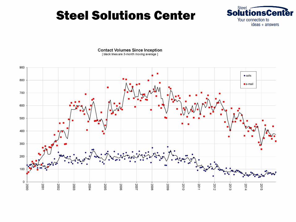
Steel Solutions Center
AISC FAQ Steel Talks 4
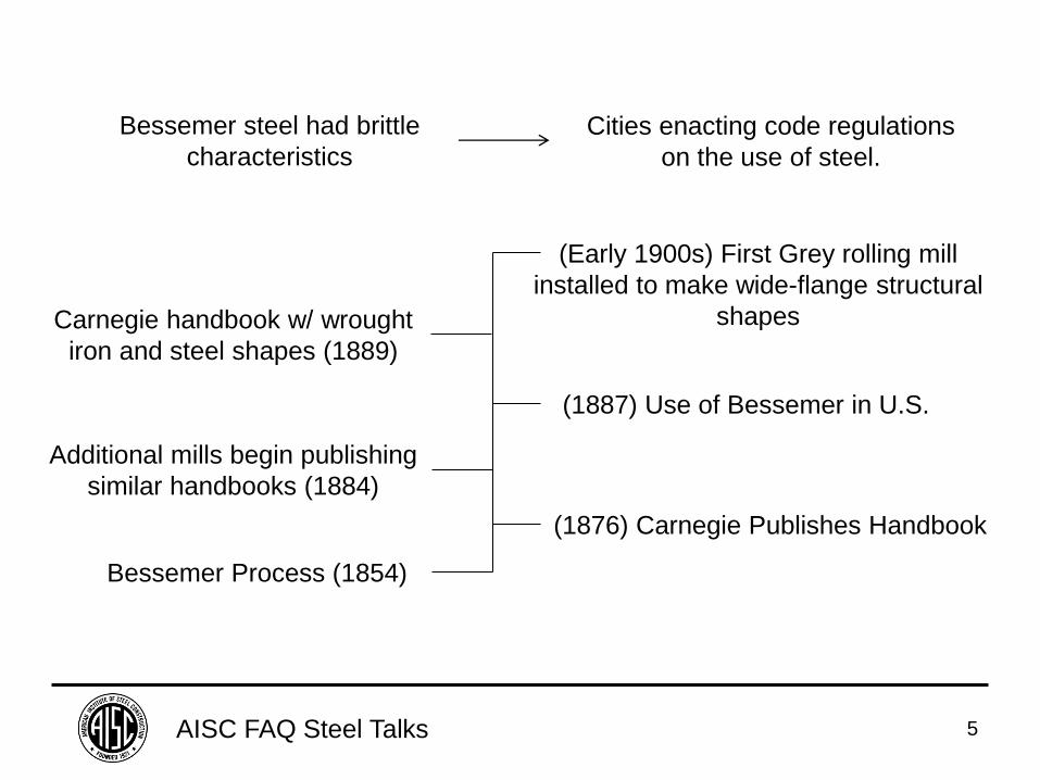
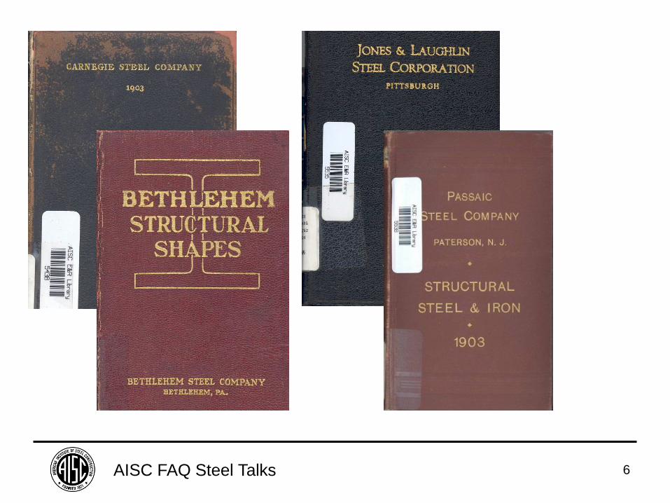
FAQ: What came before the AISC Steel
Construction Manual?
AISC FAQ Steel Talks 5
Bessemer Process (1854)
(1876) Carnegie Publishes Handbook
Additional mills begin publishing
similar handbooks (1884)
(1887) Use of Bessemer in U.S.
Carnegie handbook w/ wrought
iron and steel shapes (1889)
(Early 1900s) First Grey rolling mill
installed to make wide-flange structural
shapes
Bessemer steel had brittle
characteristics
Cities enacting code regulations
on the use of steel.
AISC FAQ Steel Talks 6
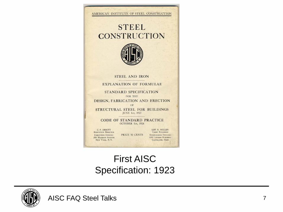
AISC FAQ Steel Talks 7
First AISC
Specification: 1923
AISC FAQ Steel Talks 8
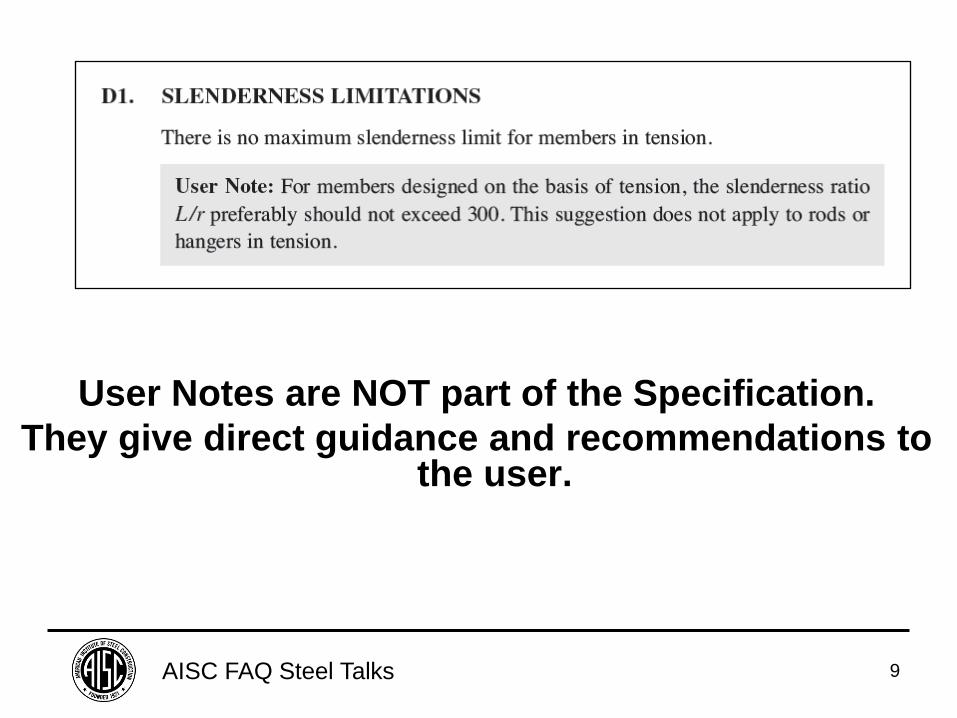
FAQ: Are User Notes part of the
Specification?
AISC FAQ Steel Talks 9
User Notes are NOT part of the Specification.
They give direct guidance and recommendations to the user.
AISC FAQ Steel Talks 10
FAQ: How are ASD & LRFD related?
AISC FAQ Steel Talks 11
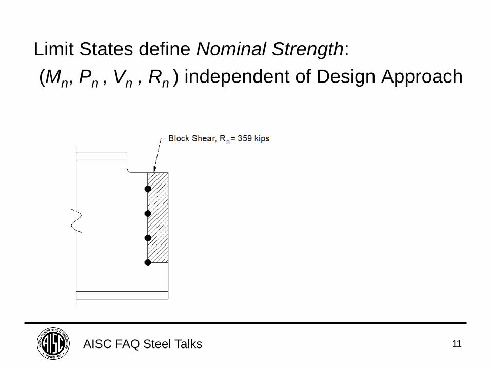
Limit States define Nominal Strength:
(Mn, Pn , Vn , Rn ) independent of Design Approach
AISC FAQ Steel Talks 12
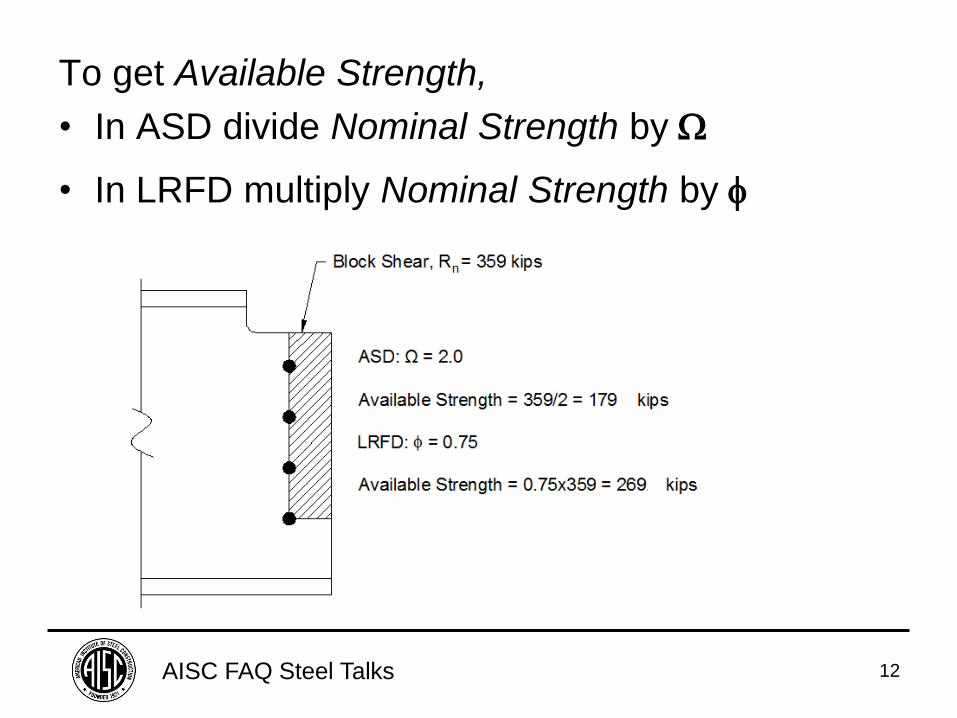
To get Available Strength,
• In ASD divide Nominal Strength by
• In LRFD multiply Nominal Strength by
AISC FAQ Steel Talks 13
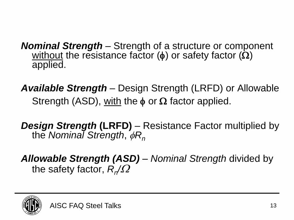
Nominal Strength – Strength of a structure or component without the resistance factor () or safety factor () applied.
Available Strength – Design Strength (LRFD) or Allowable
Strength (ASD), with the or factor applied.
Design Strength (LRFD) – Resistance Factor multiplied by the Nominal Strength, Rn
Allowable Strength (ASD) – Nominal Strength divided by the safety factor, Rn/
AISC FAQ Steel Talks 14
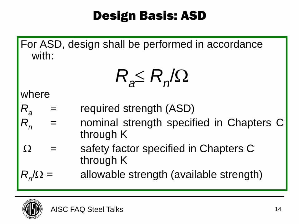
For ASD, design shall be performed in accordance with:
Ra Rn/
where
Ra = required strength (ASD)
Rn = nominal strength specified in Chapters C through K
= safety factor specified in Chapters C through K
Rn/ = allowable strength (available strength)
Design Basis: ASD
AISC FAQ Steel Talks 15
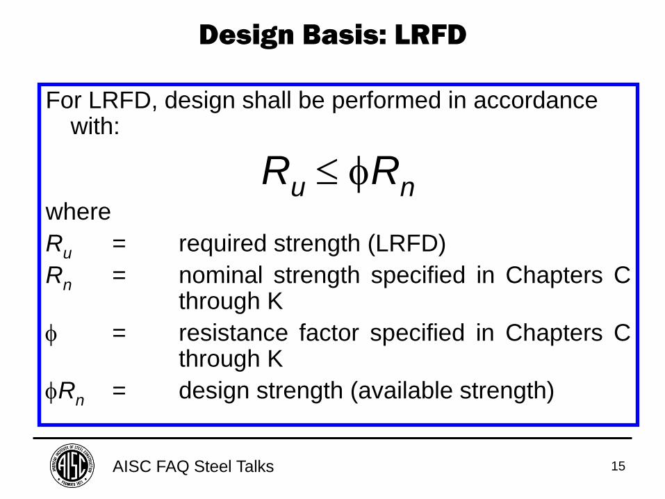
For LRFD, design shall be performed in accordance with:
Ru Rn where
Ru = required strength (LRFD)
Rn = nominal strength specified in Chapters C through K
= resistance factor specified in Chapters C through K
Rn = design strength (available strength)
Design Basis: LRFD
AISC FAQ Steel Talks 16
FAQ: How is the ASD/LRFD correlation
equilibrated?
AISC FAQ Steel Talks 17
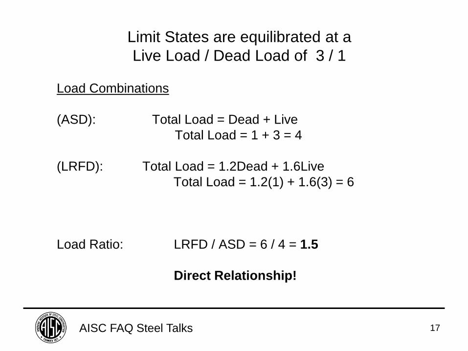
Limit States are equilibrated at a
Live Load / Dead Load of 3 / 1
Load Combinations
(ASD): Total Load = Dead + Live
Total Load = 1 + 3 = 4
(LRFD): Total Load = 1.2Dead + 1.6Live
Total Load = 1.2(1) + 1.6(3) = 6
Load Ratio: LRFD / ASD = 6 / 4 = 1.5
Direct Relationship!
AISC FAQ Steel Talks 18
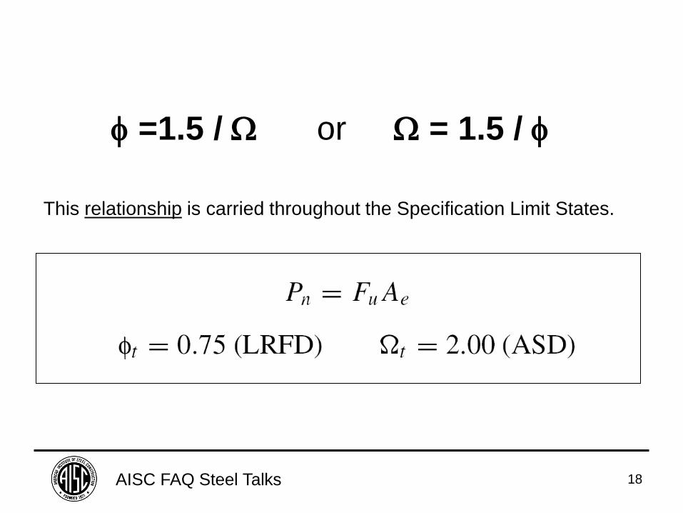
=1.5 / or = 1.5 /
This relationship is carried throughout the Specification Limit States.
AISC FAQ Steel Talks 19
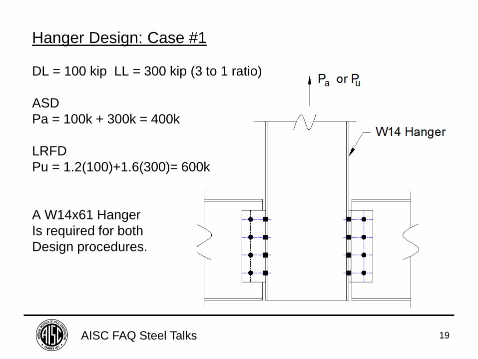
Hanger Design: Case #1
DL = 100 kip LL = 300 kip (3 to 1 ratio)
ASD
Pa = 100k + 300k = 400k
LRFD
Pu = 1.2(100)+1.6(300)= 600k
A W14x61 Hanger
Is required for both
Design procedures.
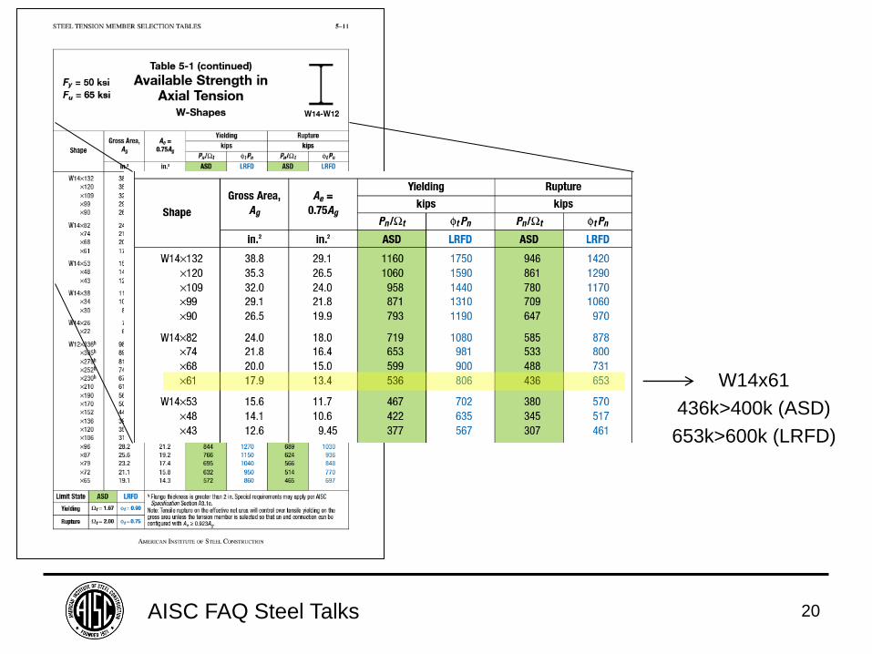
AISC FAQ Steel Talks 20
W14x61
436k>400k (ASD)
653k>600k (LRFD)
AISC FAQ Steel Talks 21
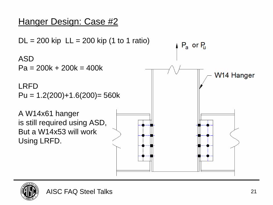
Hanger Design: Case #2
DL = 200 kip LL = 200 kip (1 to 1 ratio)
ASD
Pa = 200k + 200k = 400k
LRFD
Pu = 1.2(200)+1.6(200)= 560k
A W14x61 hanger
is still required using ASD,
But a W14x53 will work
Using LRFD.
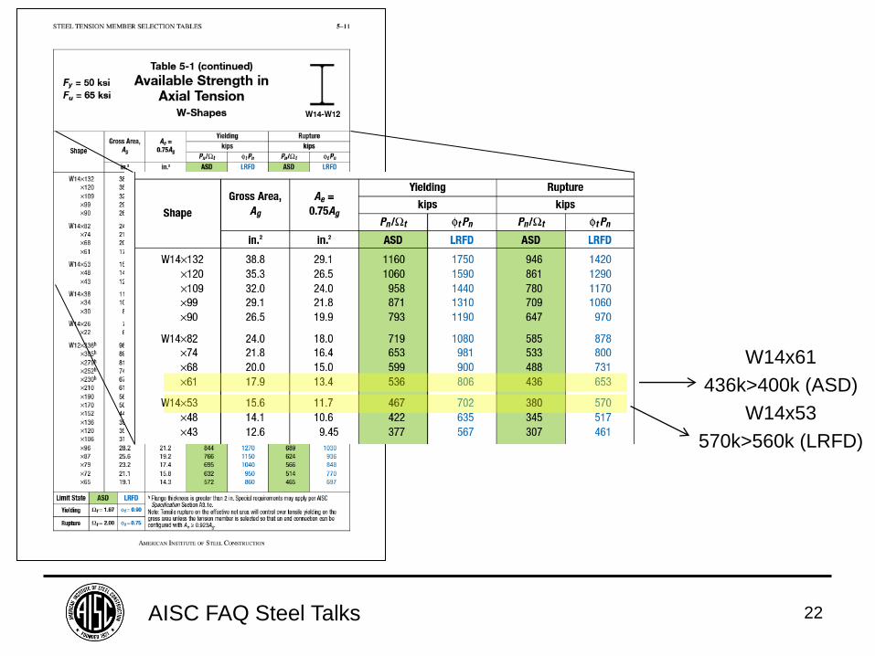
AISC FAQ Steel Talks 22
W14x61
436k>400k (ASD)
W14x53
570k>560k (LRFD)
AISC FAQ Steel Talks 23
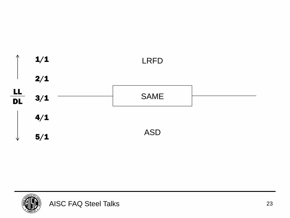
LL
DL
1/1
2/1
3/1
4/1
5/1
SAME
LRFD
ASD
AISC FAQ Steel Talks 24
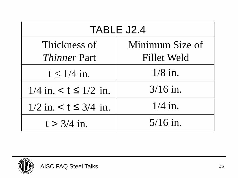
FAQ: Why is the minimum size of fillet welds
now based on the thinner part in the 2010
Specification?
AISC FAQ Steel Talks 25
TABLE J2.4
Thickness of
Thinner Part
Minimum Size of
Fillet Weld
t ≤ 1/4 in. 1/8 in.
1/4 in. < t ≤ 1/2 in. 3/16 in.
1/2 in. < t ≤ 3/4 in. 1/4 in.
t > 3/4 in. 5/16 in.
AISC FAQ Steel Talks 26
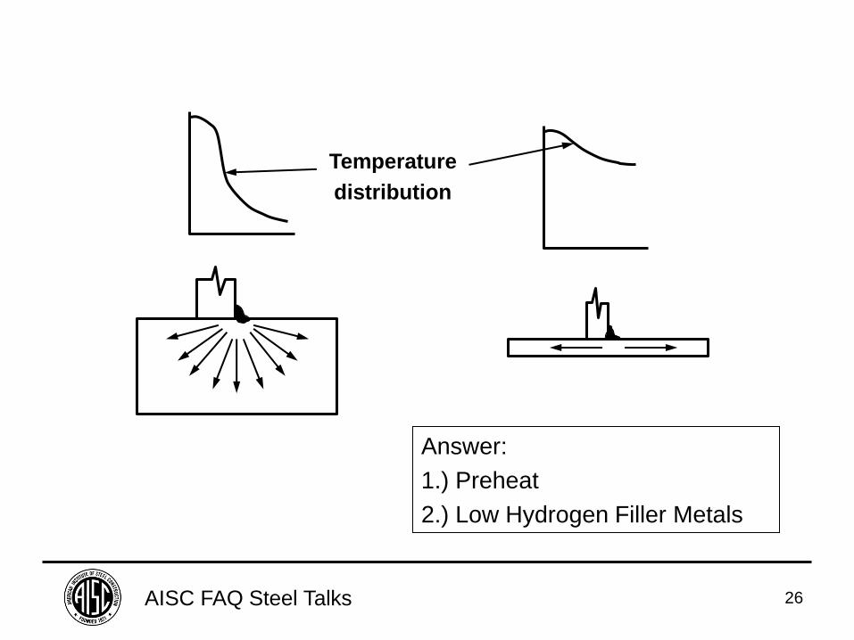
Temperature
distribution
Answer:
1.) Preheat
2.) Low Hydrogen Filler Metals
AISC FAQ Steel Talks 27
FAQ: Do HSS have to be designed for 0.93t?
Where did the factor come from?
AISC FAQ Steel Talks 28
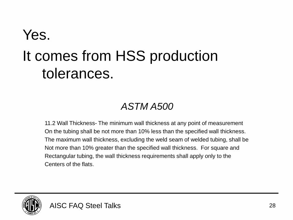
Yes.
It comes from HSS production
tolerances.
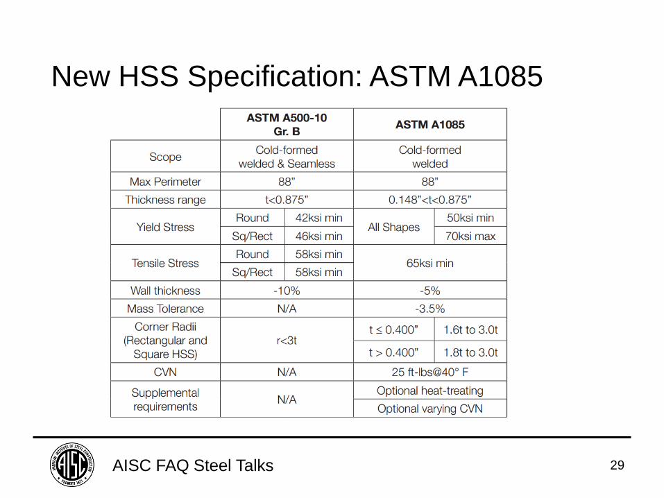
ASTM A500
11.2 Wall Thickness- The minimum wall thickness at any point of measurement
On the tubing shall be not more than 10% less than the specified wall thickness.
The maximum wall thickness, excluding the weld seam of welded tubing, shall be
Not more than 10% greater than the specified wall thickness. For square and
Rectangular tubing, the wall thickness requirements shall apply only to the
Centers of the flats.
AISC FAQ Steel Talks 29
New HSS Specification: ASTM A1085
AISC FAQ Steel Talks 30
FAQ: For single-plate connections, why
is the fillet weld size required to
be 5/8 of the plate thickness.
The plate thickness is also limited
to a maximum of 1/16” more or
less than the bolt size?
AISC FAQ Steel Talks 31
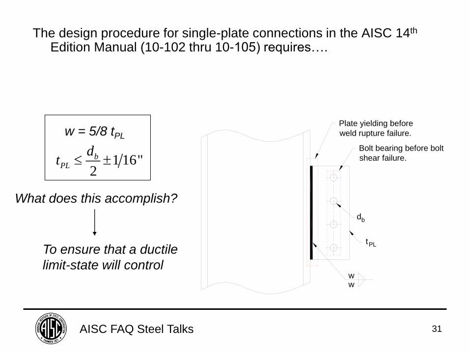
The design procedure for single-plate connections in the AISC 14th
Edition Manual (10-102 thru 10-105) requires….
1 16"2
bPL
dt
w = 5/8 tPL
To ensure that a ductile
limit-state will control ww
Plate yielding before
weld rupture failure.
Bolt bearing before bolt
shear failure.
db
tPL
What does this accomplish?
AISC FAQ Steel Talks 32
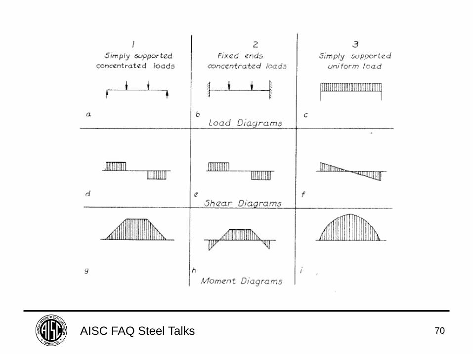
Section B3.6a Simple Connections
-A simple connection transmits a negligible moment.
-In the analysis of the structure, simple connections may be assumed to allow unrestrained rotation between the framing elements being connected.
-A simple connection shall have sufficient rotation capacity to accommodate the required rotation determined by the analysis of the structure.
AISC FAQ Steel Talks 33
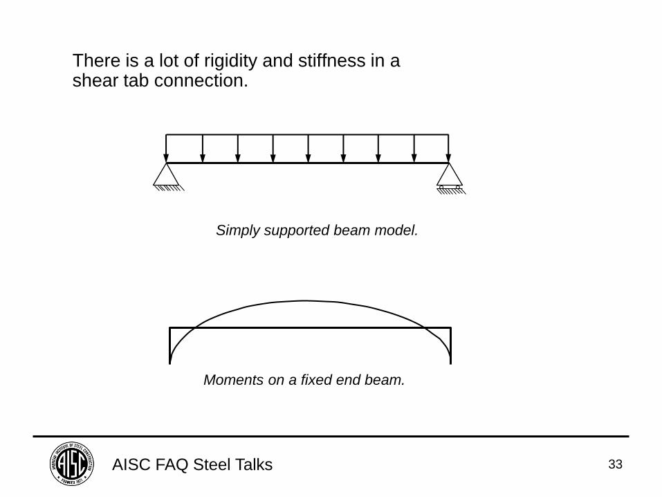
There is a lot of rigidity and stiffness in a shear tab connection.
Simply supported beam model.
Moments on a fixed end beam.
AISC FAQ Steel Talks 34
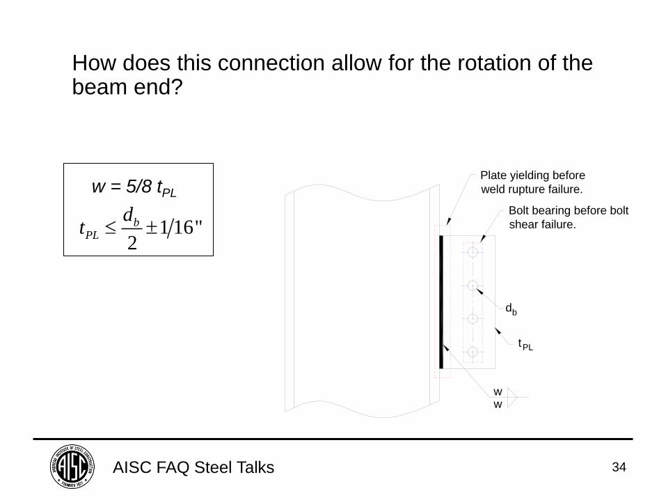
How does this connection allow for the rotation of the beam end?
1 16"2
bPL
dt
w = 5/8 tPL
ww
Plate yielding before
weld rupture failure.
Bolt bearing before bolt
shear failure.
db
tPL
AISC FAQ Steel Talks 35
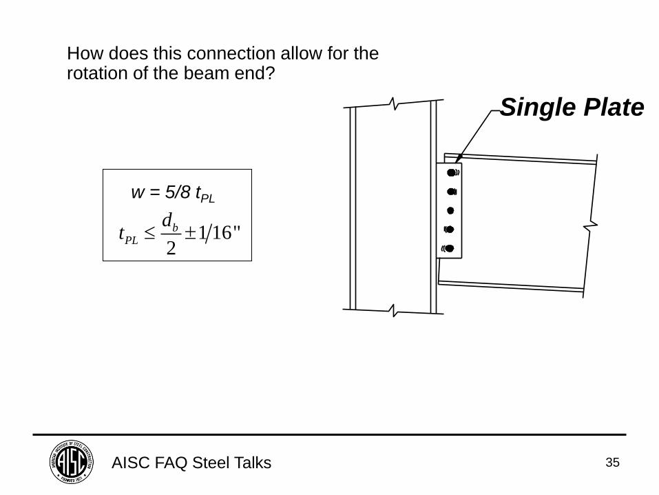
How does this connection allow for the rotation of the beam end?
1 16"2
bPL
dt
w = 5/8 tPL
Single Plate
AISC FAQ Steel Talks 36
FAQ: What is shear lag and when must it
be considered?

AISC FAQ Steel Talks 37
Check Tension Rupture: Ae = An x U = B x tPL x U
B
Tensile stress
along bar
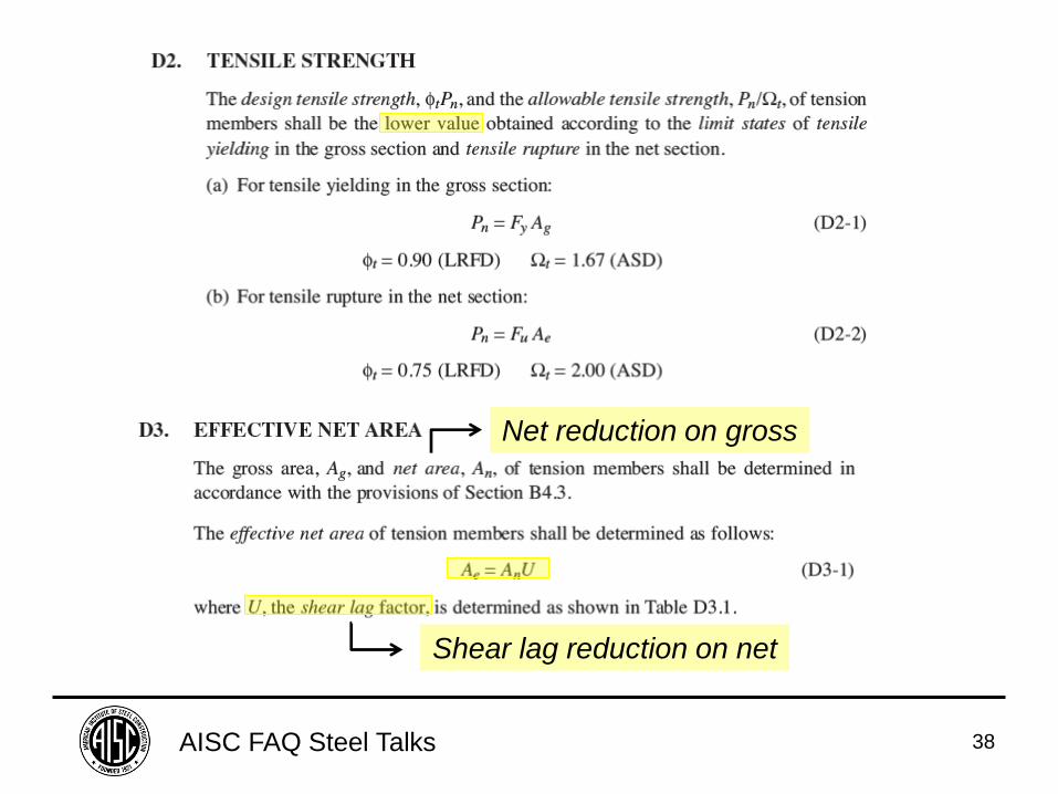
AISC FAQ Steel Talks 38
Net reduction on gross
Shear lag reduction on net
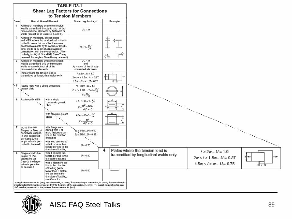
AISC FAQ Steel Talks 39
AISC FAQ Steel Talks 40
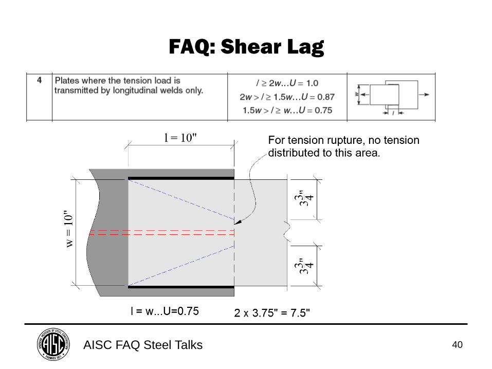
FAQ: Shear Lag
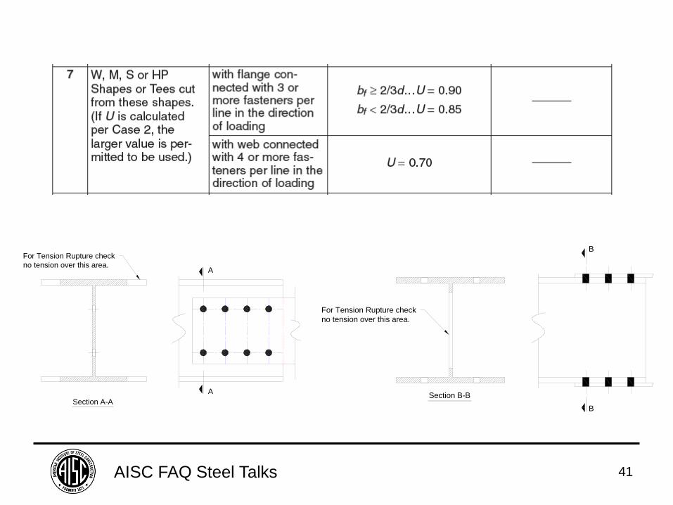
AISC FAQ Steel Talks 41
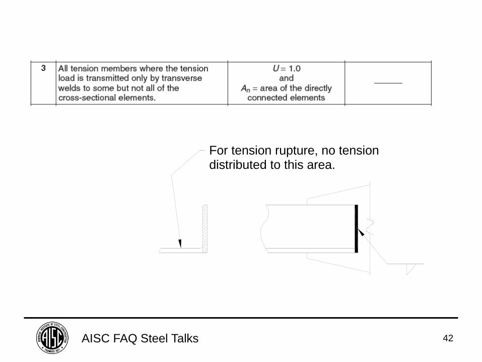
For Tension Rupture check
no tension over this area.
A
A
Section A-A
For Tension Rupture check
no tension over this area.
B
B
Section B-B
AISC FAQ Steel Talks 42
For tension rupture, no tensiondistributed to this area.
AISC FAQ Steel Talks 43
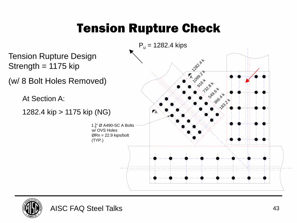
Tension Rupture Check
1 18" Ø A490-SC A Bolts
w/ OVS Holes
ØRn = 22.9 kips/bolt
(TYP.)
A
A
183.
2 k
366.
4 k
549.
6 k
732.
8 k
916
k1099
.2 k
1282
.4 k
Tension Rupture Design
Strength = 1175 kip
(w/ 8 Bolt Holes Removed)
At Section A:
1282.4 kip > 1175 kip (NG)
Pu = 1282.4 kips
AISC FAQ Steel Talks 44
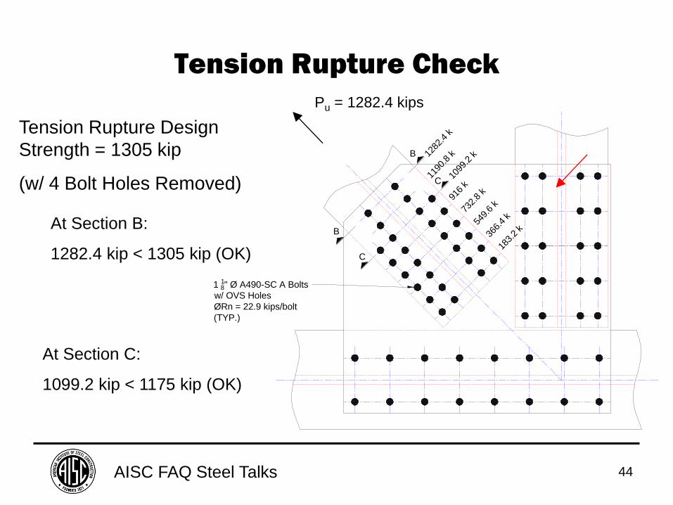
Tension Rupture Check
Tension Rupture Design
Strength = 1305 kip
(w/ 4 Bolt Holes Removed)
At Section B:
1282.4 kip < 1305 kip (OK)
1 18" Ø A490-SC A Bolts
w/ OVS Holes
ØRn = 22.9 kips/bolt
(TYP.)
B
B
C
C
183.
2 k
366.
4 k
549.
6 k
732.
8 k
916
k
1099
.2 k12
82.4
k
1190
.8 k
At Section C:
1099.2 kip < 1175 kip (OK)
Pu = 1282.4 kips
AISC FAQ Steel Talks 45
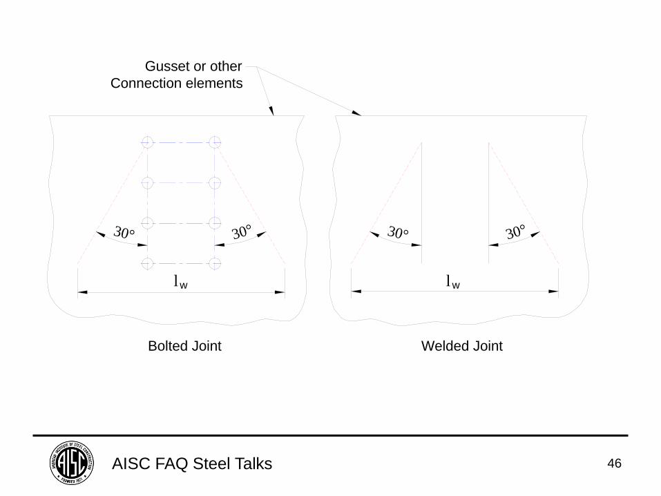
FAQ: In many design examples in the 14th Edition Manual of Steel Construction, yielding and buckling in a
gusset plate or similar fitting are checked on a Whitmore section.
What is a Whitmore section?
AISC FAQ Steel Talks 46
lw lw
30° 30° 30° 30°
Bolted Joint Welded Joint
Gusset or other
Connection elements
AISC FAQ Steel Talks 47
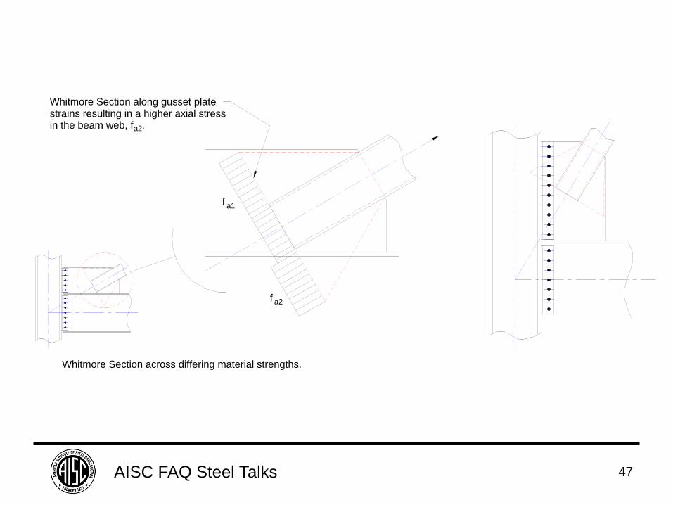
f a1
f a2
Whitmore Section along gusset platestrains resulting in a higher axial stressin the beam web, f .a2
Whitmore Section across differing material strengths.
AISC FAQ Steel Talks 48
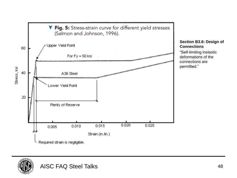
Section B3.6: Design of
Connections
“Self-limiting inelastic
deformations of the
connections are
permitted.”
AISC FAQ Steel Talks 49
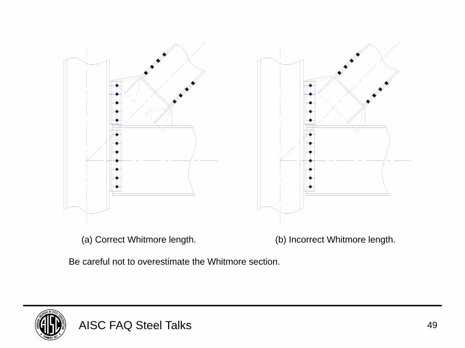
(a) Correct Whitmore length. (b) Incorrect Whitmore length.
Be careful not to overestimate the Whitmore section.
AISC FAQ Steel Talks 50
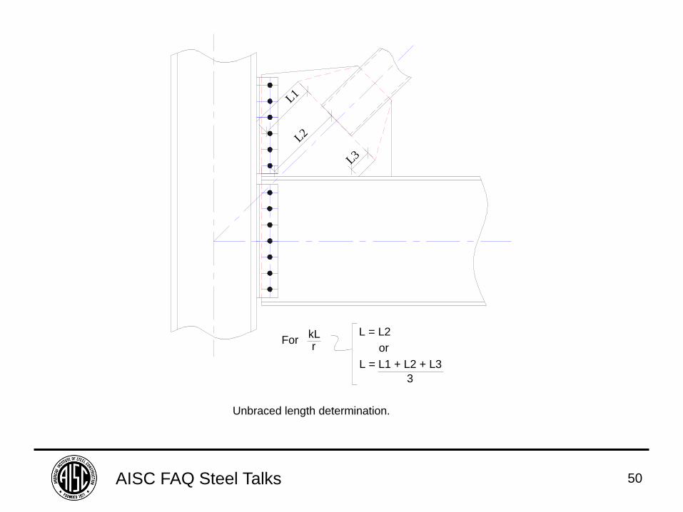
Unbraced length determination.
L1
L2
L3
ForkLr
L = L2
or
L = L1 + L2 + L3
3
AISC FAQ Steel Talks 51
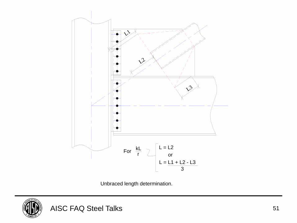
Unbraced length determination.
L1
L2
L3
ForkLr
L = L2
or
L = L1 + L2 - L3
3
AISC FAQ Steel Talks 52
FAQ: Why is use of the least possible
fillet weld size desirable?
AISC FAQ Steel Talks 53
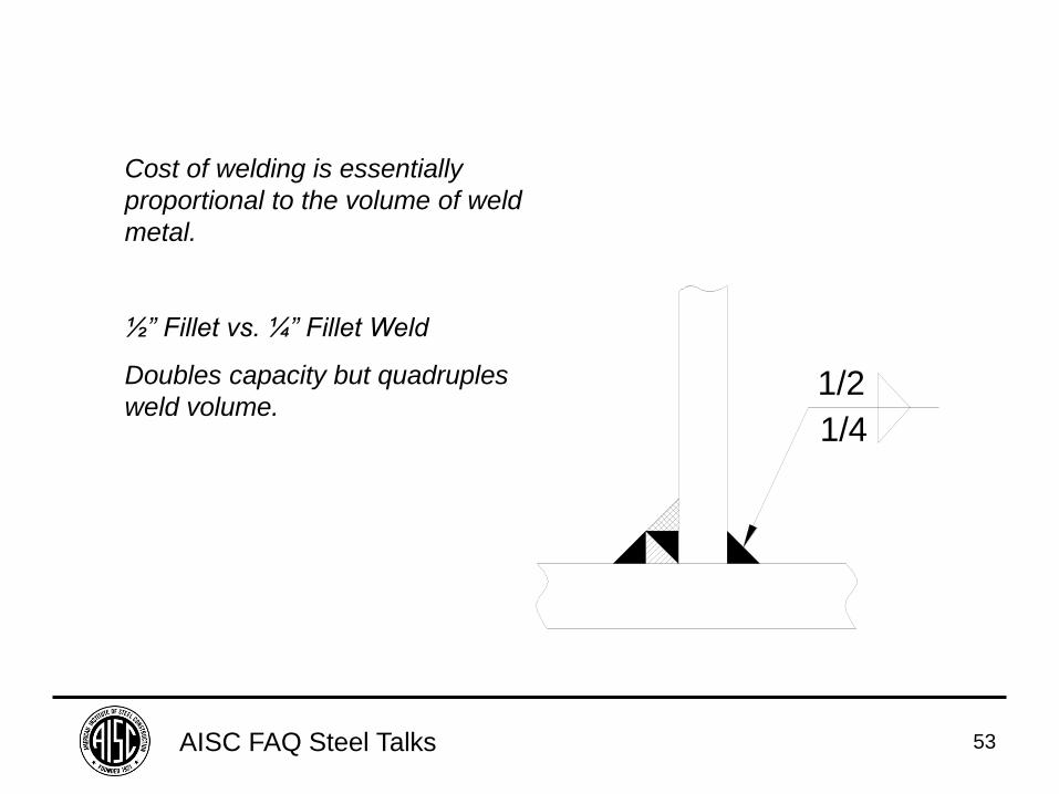
1/4
1/2
Cost of welding is essentially
proportional to the volume of weld
metal.
½” Fillet vs. ¼” Fillet Weld
Doubles capacity but quadruples
weld volume.
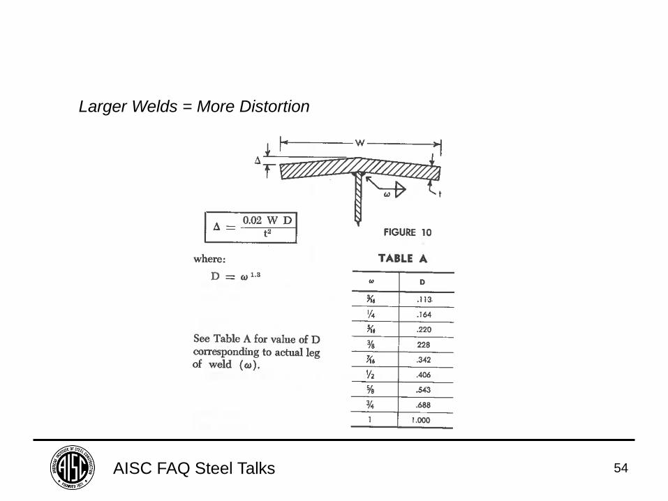
AISC FAQ Steel Talks 54
Larger Welds = More Distortion
AISC FAQ Steel Talks 55
FAQ: Why are fillet welds preferred over
groove welds?
AISC FAQ Steel Talks 56
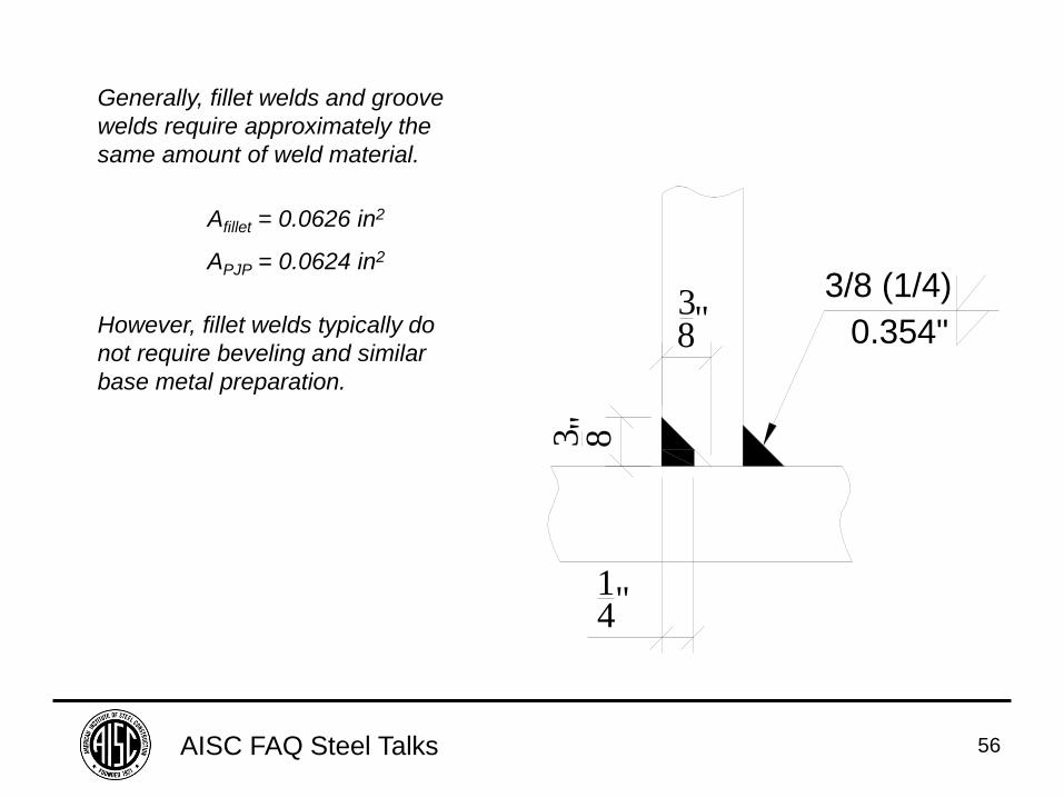
Generally, fillet welds and groove
welds require approximately the
same amount of weld material.
However, fillet welds typically do
not require beveling and similar
base metal preparation.
Afillet = 0.0626 in2
APJP = 0.0624 in2
0.354"
3/8 (1/4)38"
14"
3 8"
AISC FAQ Steel Talks 57
FAQ: When a weld is placed between
plates forming an angle that is less than
60 degrees, why is a Z-loss factor applied
to determine the effective throat?
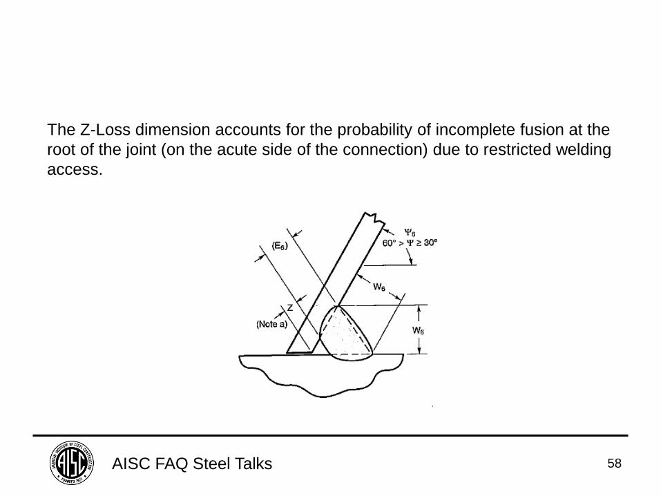
AISC FAQ Steel Talks 58
The Z-Loss dimension accounts for the probability of incomplete fusion at the
root of the joint (on the acute side of the connection) due to restricted welding
access.
AISC FAQ Steel Talks 59
FAQ: When an extended end-plate moment connection is specified as slip-critical, must the slip resistance of the
bolts at the tension flange be reduced for the tension present?
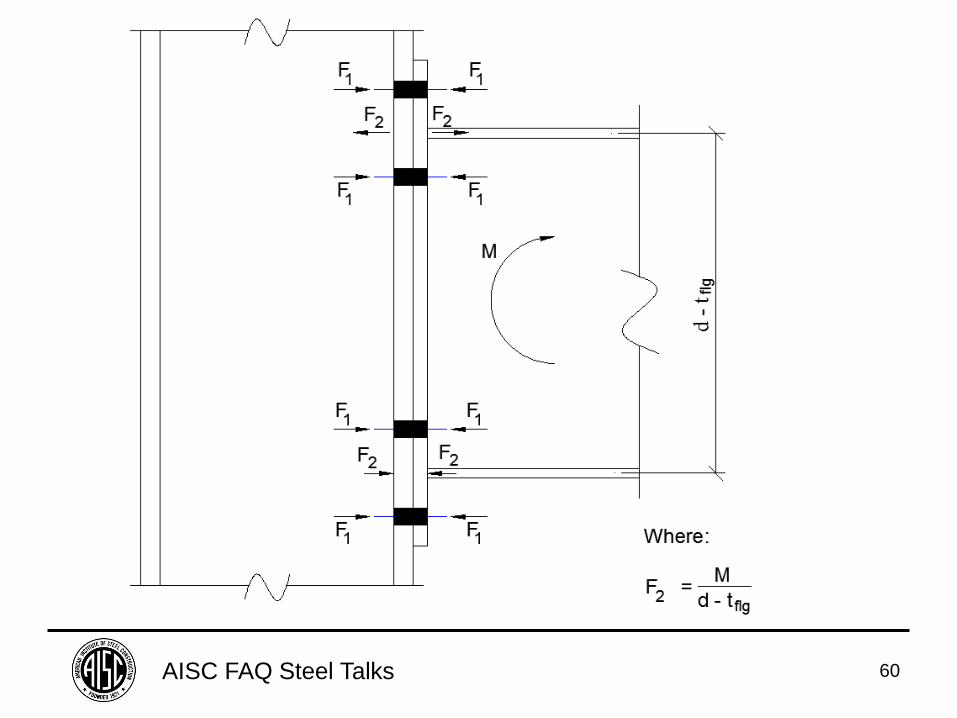
AISC FAQ Steel Talks 60
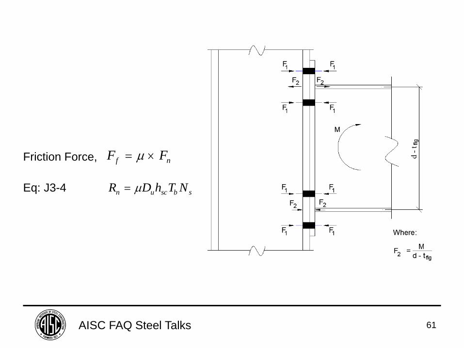
AISC FAQ Steel Talks 61
F Ff n Friction Force,
R D h T Nn u sc b s Eq: J3-4
AISC FAQ Steel Talks 62
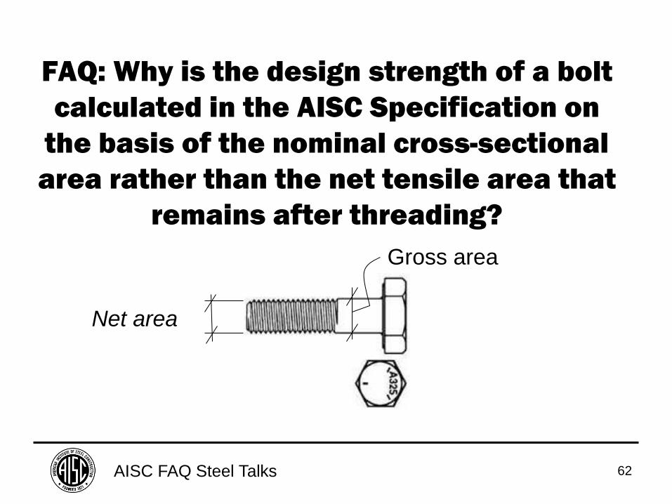
FAQ: Why is the design strength of a bolt
calculated in the AISC Specification on
the basis of the nominal cross-sectional
area rather than the net tensile area that
remains after threading?
Net area
Gross area
AISC FAQ Steel Talks 63
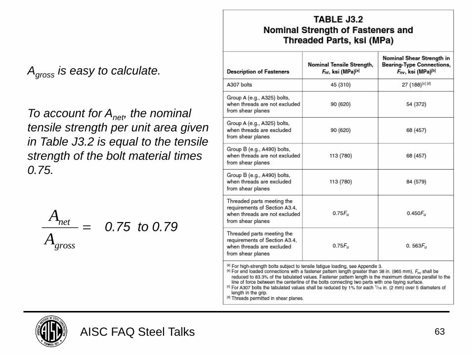
A
A
net
gross
0.75 to 0.79
Agross is easy to calculate.
To account for Anet, the nominal
tensile strength per unit area given
in Table J3.2 is equal to the tensile
strength of the bolt material times
0.75.
AISC FAQ Steel Talks 64
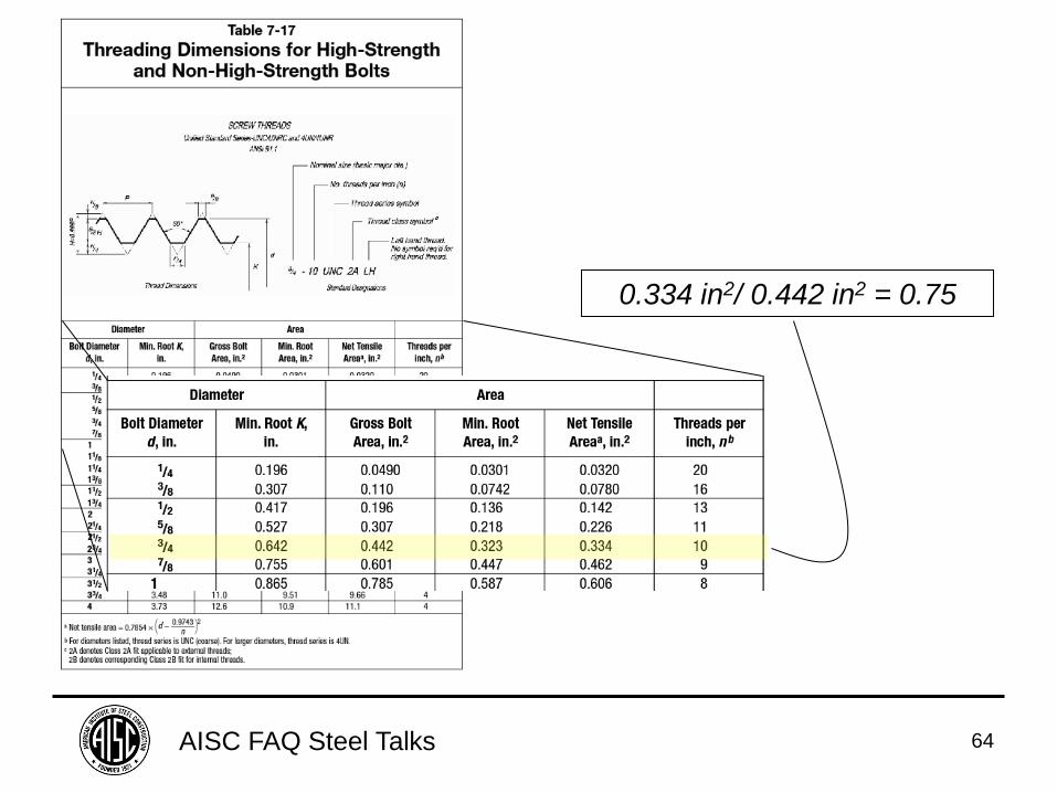
0.334 in2/ 0.442 in2 = 0.75
AISC FAQ Steel Talks 65
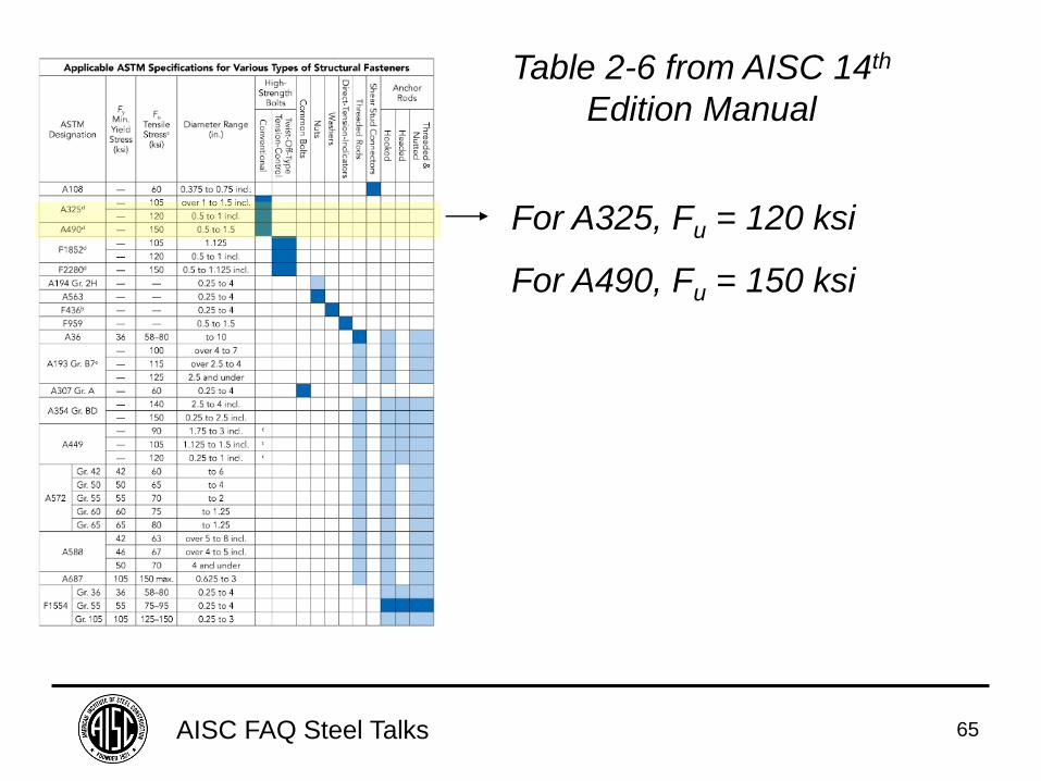
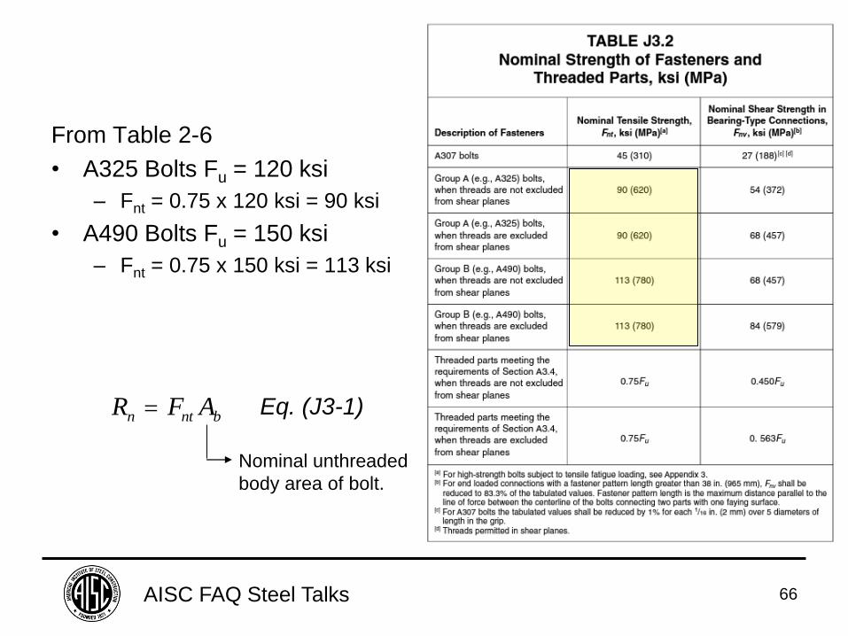
For A325, Fu = 120 ksi
For A490, Fu = 150 ksi
Table 2-6 from AISC 14th
Edition Manual
AISC FAQ Steel Talks 66
From Table 2-6
• A325 Bolts Fu = 120 ksi
– Fnt = 0.75 x 120 ksi = 90 ksi
• A490 Bolts Fu = 150 ksi
– Fnt = 0.75 x 150 ksi = 113 ksi
R F An nt b Eq. (J3-1)
Nominal unthreaded
body area of bolt.
AISC FAQ Steel Talks 67
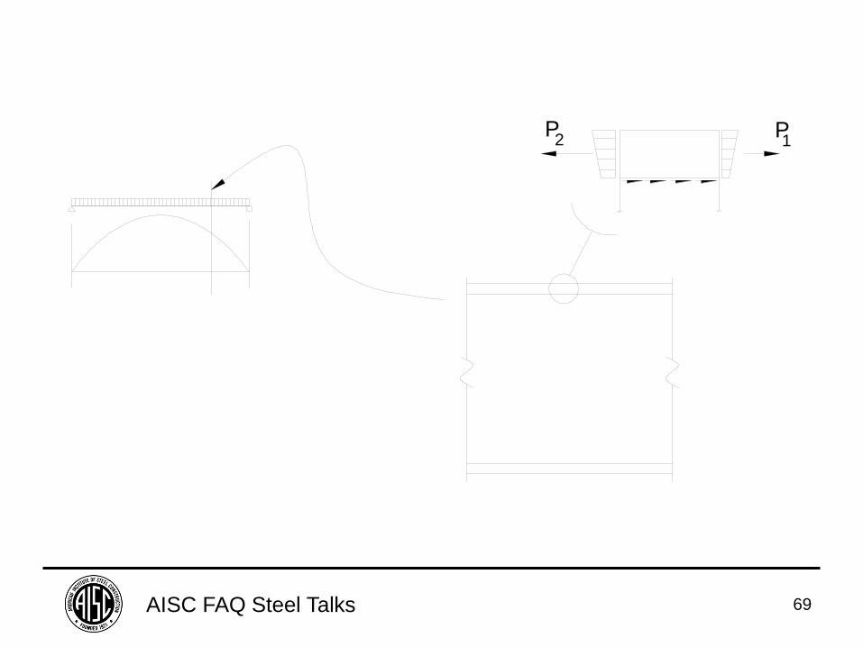
FAQ: In a built-up I-shaped cross-section,
how are welds connecting the plates
designed?
AISC FAQ Steel Talks 68
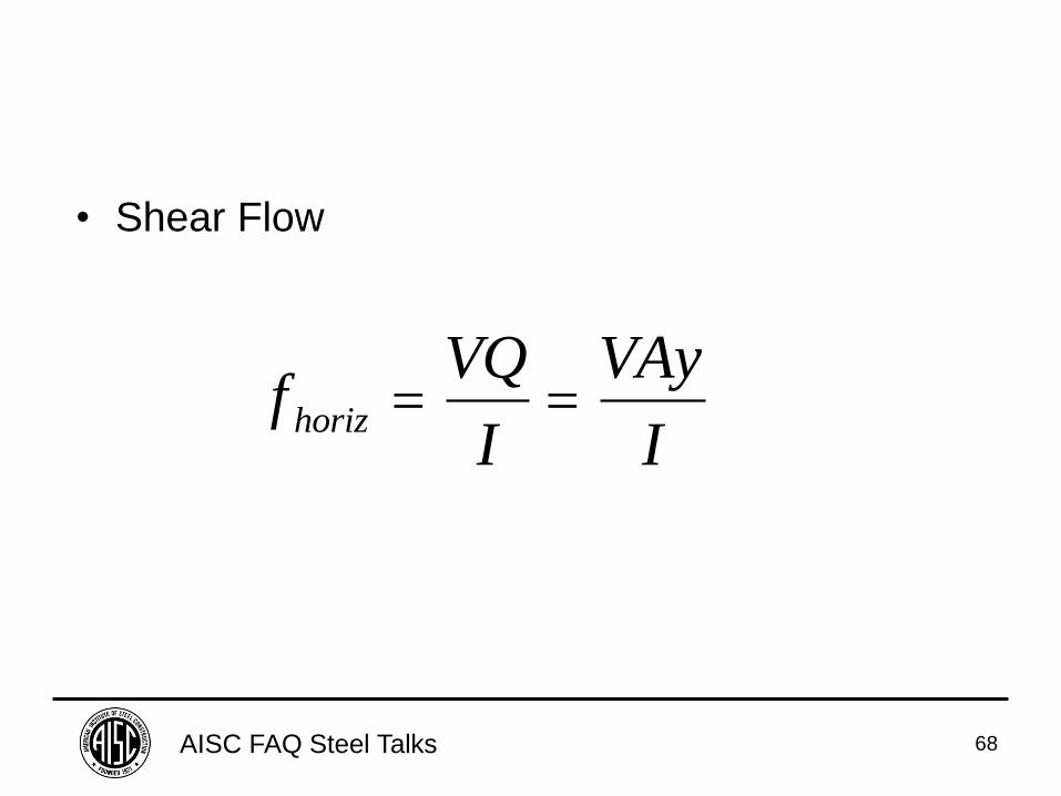
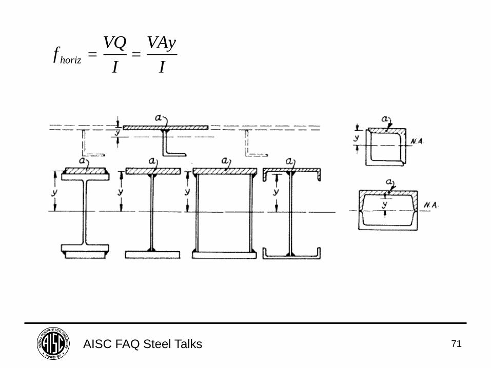
• Shear Flow
fVQ
I
VAy
Ihoriz
AISC FAQ Steel Talks 69
P1
P2
AISC FAQ Steel Talks 70
AISC FAQ Steel Talks 71
fVQ
I
VAy
Ihoriz
AISC FAQ Steel Talks 72
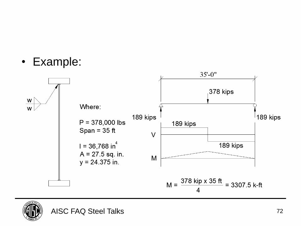
• Example:
AISC FAQ Steel Talks 73
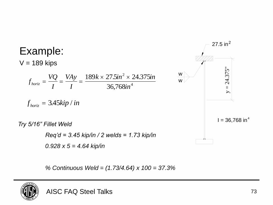
Example: V = 189 kips
fVQ
I
VAy
I
k in in
inhoriz
189 27 5 24 375
36 768
2
4
. .
,
I = 36,768 in4
w
w
y =
24.3
75"
27.5 in2
f kip inhoriz 345. /
Try 5/16” Fillet Weld
Req’d = 3.45 kip/in / 2 welds = 1.73 kip/in
0.928 x 5 = 4.64 kip/in
% Continuous Weld = (1.73/4.64) x 100 = 37.3%
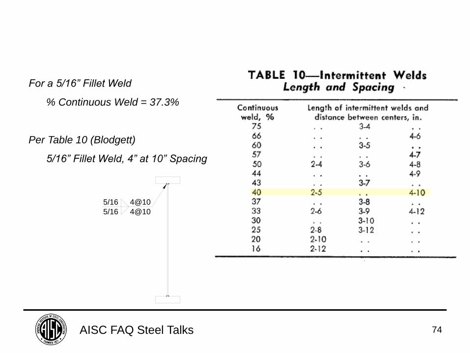
AISC FAQ Steel Talks 74
For a 5/16” Fillet Weld
% Continuous Weld = 37.3%
Per Table 10 (Blodgett)
5/16” Fillet Weld, 4” at 10” Spacing
5/16
5/16
4@10
4@10
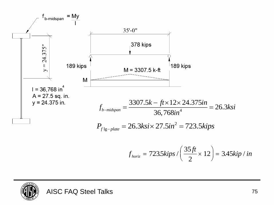
AISC FAQ Steel Talks 75
4
3307.5 12 24.37526.3
36,768b midspan
k ft inf ksi
in
2
lg 26.3 27.5 723.5f plateP ksi in kips
f kipsft
kip inhoriz
7235
35
212 345. / . /
AISC FAQ Steel Talks 76
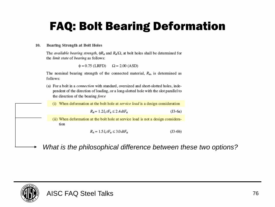
FAQ: Bolt Bearing Deformation
What is the philosophical difference between these two options?
AISC FAQ Steel Talks 77
1 4"
MA
X.
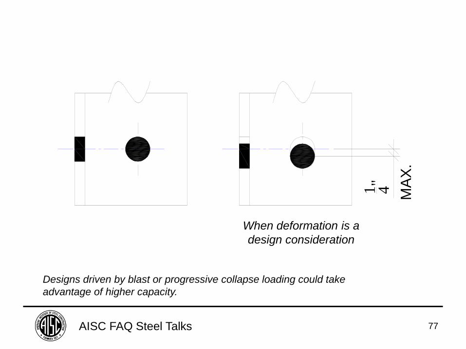
When deformation is a
design consideration
Designs driven by blast or progressive collapse loading could take
advantage of higher capacity.
AISC FAQ Steel Talks 78
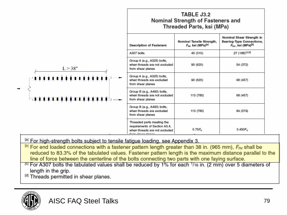
FAQ: As indicated in the 2010 AISC
Specification Table J3.2, when the pattern of
fasteners in a bolted joint exceeds 38 in. in
length, tabulated design strengths should be
reduced to 83.3% of the tabulated values. Why?
AISC FAQ Steel Talks 79
AISC FAQ Steel Talks 80
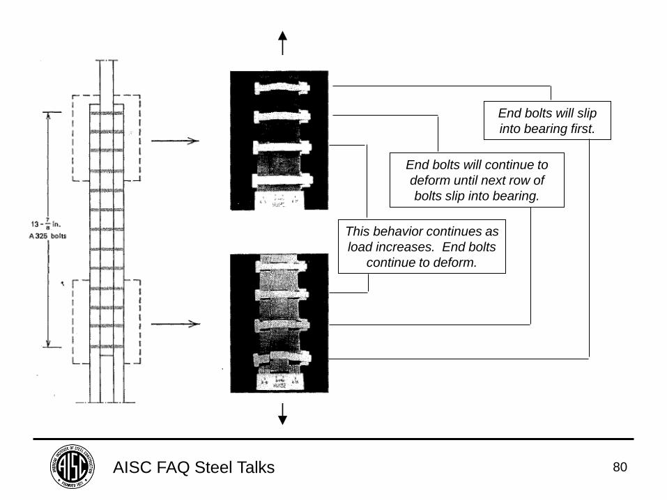
End bolts will continue to
deform until next row of
bolts slip into bearing.
End bolts will slip
into bearing first.
This behavior continues as
load increases. End bolts
continue to deform.
AISC FAQ Steel Talks 81
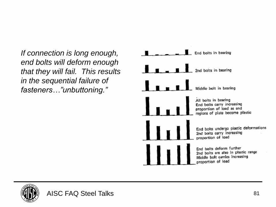
If connection is long enough,
end bolts will deform enough
that they will fail. This results
in the sequential failure of
fasteners…”unbuttoning.”
AISC FAQ Steel Talks 82
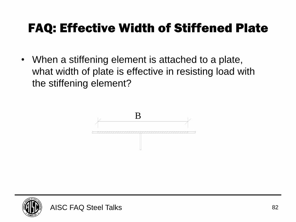
FAQ: Effective Width of Stiffened Plate
• When a stiffening element is attached to a plate,
what width of plate is effective in resisting load with
the stiffening element?
B
AISC FAQ Steel Talks 83
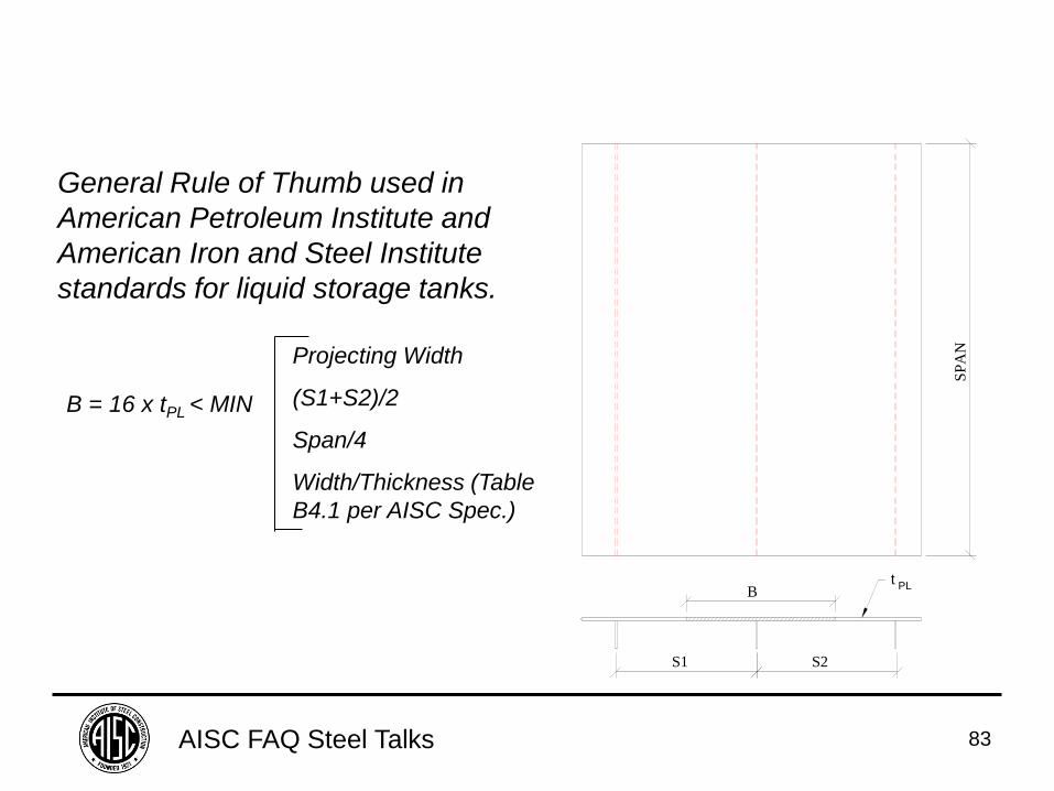
General Rule of Thumb used in
American Petroleum Institute and
American Iron and Steel Institute
standards for liquid storage tanks.
SP
AN
S1 S2
Bt
PL
B = 16 x tPL < MIN
Projecting Width
(S1+S2)/2
Span/4
Width/Thickness (Table
B4.1 per AISC Spec.)
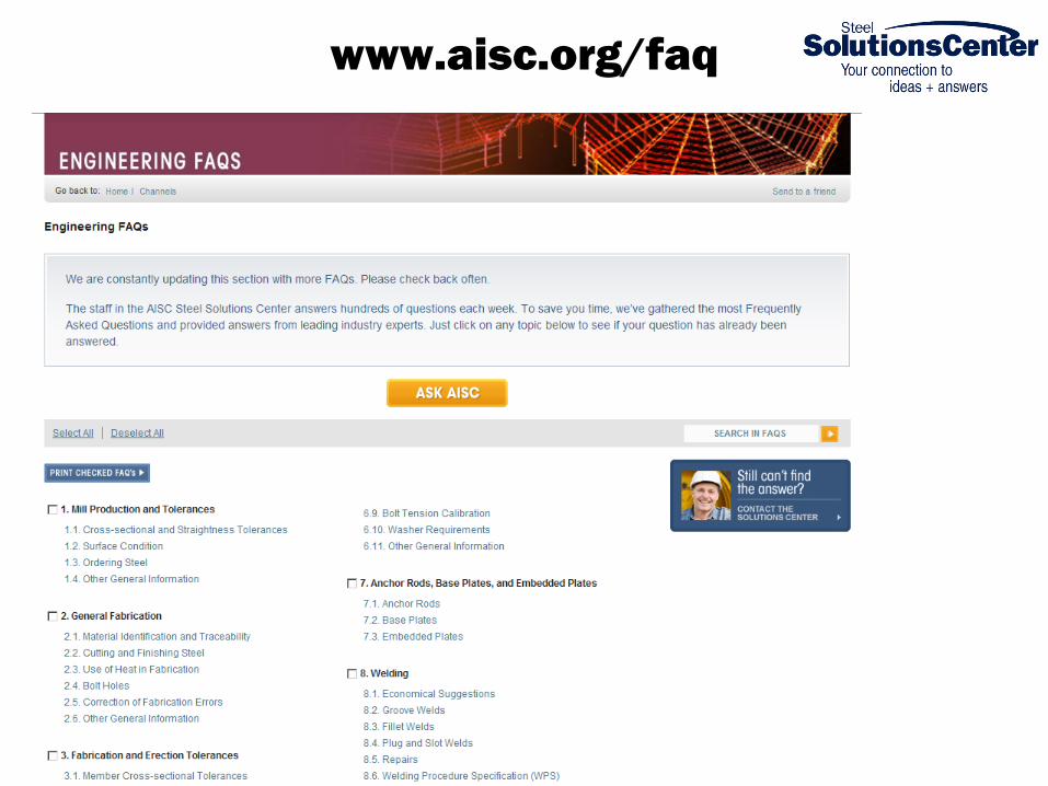
www.aisc.org/faq
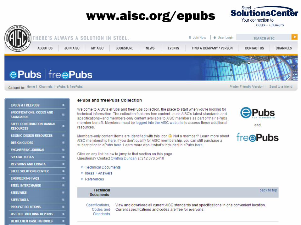
www.aisc.org/epubs
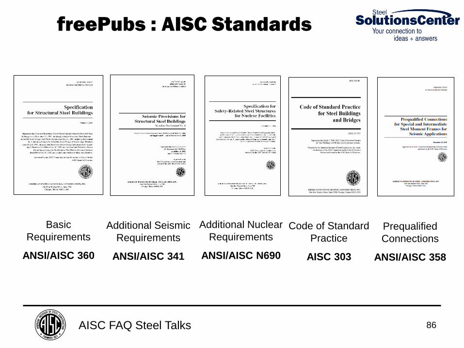
AISC FAQ Steel Talks 86
Basic
Requirements
ANSI/AISC 360
Additional Seismic
Requirements
ANSI/AISC 341
Additional Nuclear
Requirements
ANSI/AISC N690
Code of Standard
Practice
AISC 303
freePubs : AISC Standards
Prequalified
Connections
ANSI/AISC 358
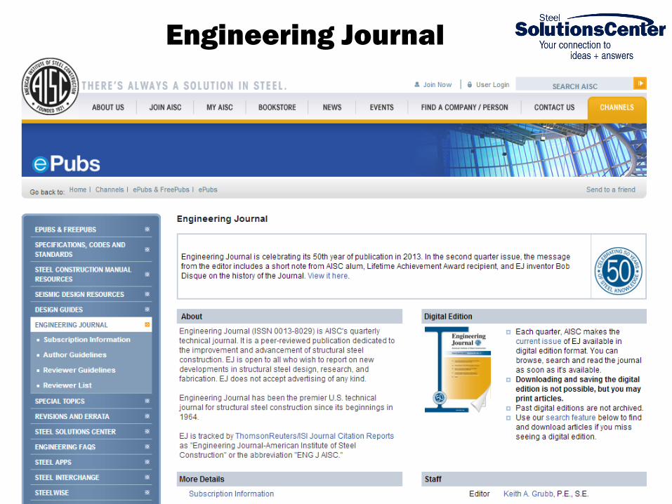
Engineering Journal
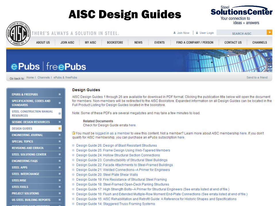
AISC Design Guides
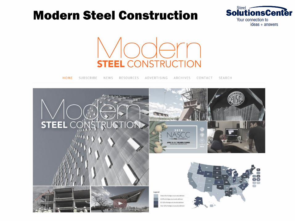
Modern Steel Construction

AISC FAQ Steel Talks 90
SSC Staff
Joe Dardis Katherine Quigg
Carlo Lini Tabitha Stine
Jennie Traut-Todaro
Larry Muir
AISC FAQ Steel Talks 92
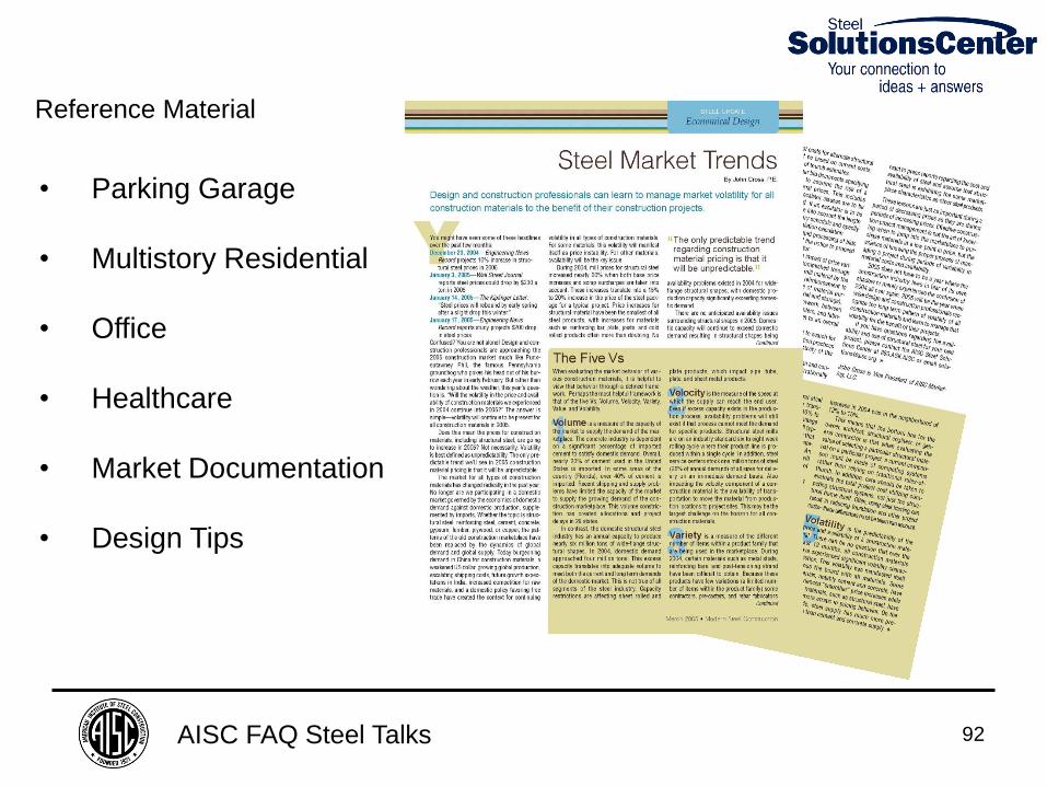
• Parking Garage
• Multistory Residential
• Office
• Healthcare
• Market Documentation
• Design Tips
Reference Material
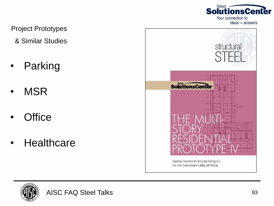
AISC FAQ Steel Talks 93
• Parking
• MSR
• Office
• Healthcare
Project Prototypes
& Similar Studies
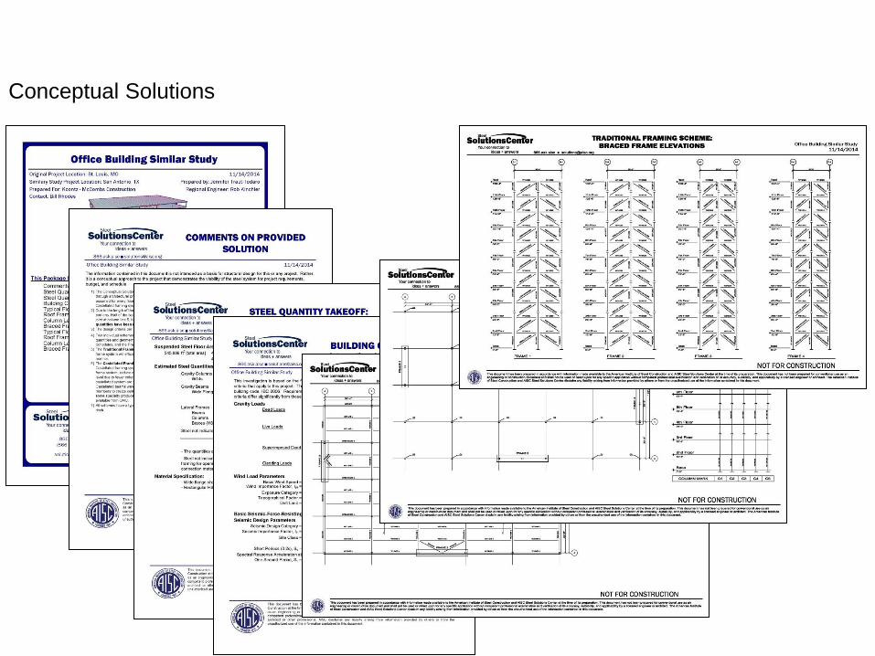
Conceptual Solutions
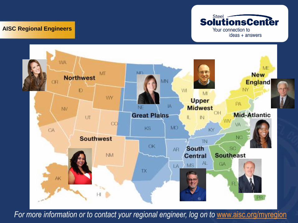
AISC Regional Engineers
For more information or to contact your regional engineer, log on to www.aisc.org/myregion

AISC FAQ Steel Talks 96
A second option for the location of the
“branding title.” A second option for the location of the
“branding title.”
There’s always a solution in steel.
Thank You
American Institute of Steel Construction
One East Wacker Drive, Suite 700
Chicago, IL 60601
Jennie Traut-Todaro