Embed Size (px)
Citation preview
SANYO DENKI Technical Report No.19 May 2005 14
Development of "SANUPS P83A" PowerConditioner for Photovoltaic Systems
Features
Akinori Matsuzaki Yuuji Wada Takashi Kobayashi Yuuzo Kubota
1. Introduction
Since the Kyoto Protocol went in to effect in February of 2005, wehave witnessed increased interest in solar energy as a source ofpollution-free energy that does not contribute to global warming. Untilnow, wide need of photovoltaic systems with output of 100kW ormore for industrial purposes has lated behind residential use due to thespace constraints involved in installing photovoltaic panels, as well asthe high operating costs of these systems. However, certain industrialfields have undergone a recent increase in demand for over 100kWphotovoltaic systems, such as photovoltaic solar mega-projects led byJapan’s Ministry of the Environment, along with water purificationfacilities and other places where a large surface area is available forthe installation of solar panels.
In the past, Sanyo Denki’s conventional "SANUPS PMC-TD"model was often used in photovoltaic systems with capacities over50kW by simply combining several units together in a singleinstallation. In light of current demands for power conditionersexceeding 100kW that require less space for installation, use fewercables, and permit easier maintenance, however, such a solution isbeginning to appear less viable.
To respond to the needs of the market, Sanyo Denki has developedthe "SANUPS P83A" power conditioner, capable of handling large-scale photovoltaic systems, and contributing to an overallimprovement in their quality.
Details on the development of the new "SANUPS P83A" powerconditioner are outlined below.
2. Development Background
Our conventional "SANUPS PMC-TD" model has serial capacitiesranging from 10kW to 50kW. This product has accommodated large-scale systems of 50kW or greater by combining several units in asingle installation, such as using four 50kW units in a photovoltaicsystem with a 200kW capacity, for example.
Since the "SANUPS PMC-TD" offered expandable functions, suchas isolated operation and charged operation functions, as well as autility-connected operation function found in a large percentage ofphotovoltaic systems, it required redundant structures, and relativelyhigh costs.
In addition, the power conditioner also required measures toprevent current leakage due to stray capacitance, a phenomenonpeculiar to photovoltaic cells, when it was configured into large-scalesystems.
This situation is in contrast to initiatives to reduce the cost of
adopting the system, including the expense of installing the powerconditioner, in order to make the overall system more economical.
Taking the limitations of the "SANUPS PMC-TD" intoconsideration, we developed the new "SANUPS P83A" powerconditioner, capable of 100kW output and designed for exclusive useof utility system, the mainstream of photovoltaic systems.
3. Features
3.1 100kW Output Capacity The "SANUPS P83A" has a 100kW output capacity, and is
equipped with a power switching device, controlled power source,operation switches, displays, and utility protective device.
This unit is also capable of receiving signals (after conversion by atransducer) sent from meteorological measurement devices such aspyanometer and thermometers, a feature that is critical to field tests ofphotovoltaic technology projects such as those conducted by Japan’sNew Energy and Industrial Technology Development Organization(NEDO).
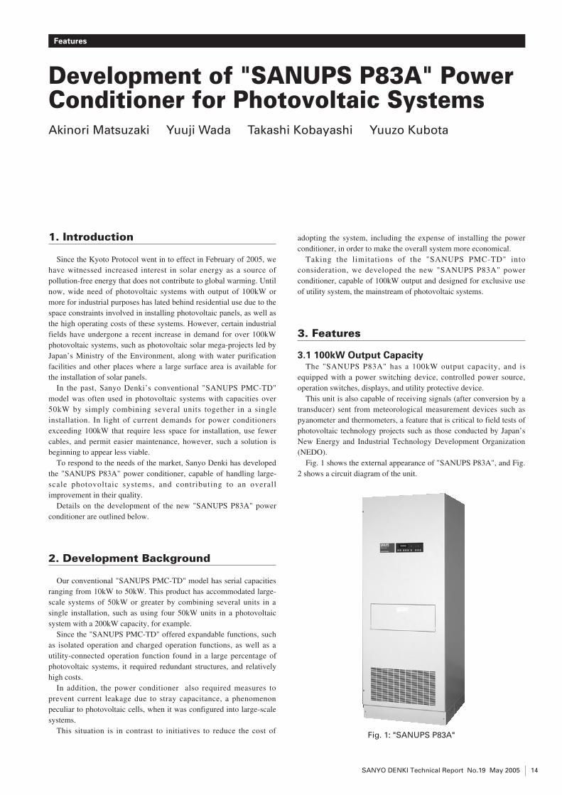
Fig. 1 shows the external appearance of "SANUPS P83A", and Fig.2 shows a circuit diagram of the unit.
Fig. 1: "SANUPS P83A"
3.2 Insulation Transformer TypeWhen a large-scale photovoltaic system is configured, the required
number of photovoltaic modules increases; as a result, the straycapacitance between the solar cells and the ground is increased,causing a larger leakage current. To prevent this leakage current, aninsulation transformer with a commercial frequency has been installedon both the photovoltaic module side and the utility system side. Theuse of a utility frequency insulation transformer has also eliminated acircuit of DC current detection.
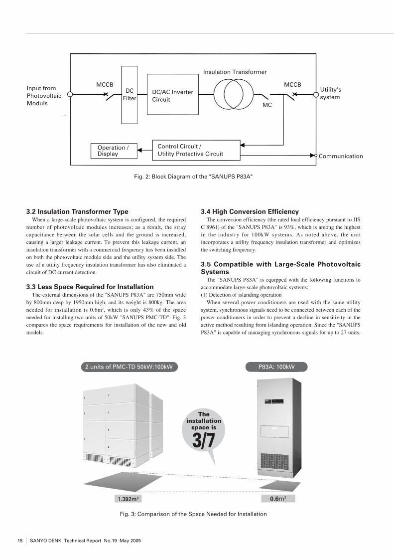
3.3 Less Space Required for InstallationThe external dimensions of the "SANUPS P83A" are 750mm wide
by 800mm deep by 1950mm high, and its weight is 800kg. The areaneeded for installation is 0.6m2, which is only 43% of the spaceneeded for installing two units of 50kW "SANUPS PMC-TD". Fig. 3compares the space requirements for installation of the new and oldmodels.
3.4 High Conversion EfficiencyThe conversion efficiency (the rated load efficiency pursuant to JIS
C 8961) of the "SANUPS P83A" is 93%, which is among the highestin the industry for 100kW systems. As noted above, the unitincorporates a utility frequency insulation transformer and optimizesthe switching frequency.
3.5 Compatible with Large-Scale PhotovoltaicSystems
The "SANUPS P83A" is equipped with the following functions toaccommodate large-scale photovoltaic systems:(1) Detection of islanding operation
When several power conditioners are used with the same utilitysystem, synchronous signals need to be connected between each of thepower conditioners in order to prevent a decline in sensitivity in theactive method resulting from islanding operation. Since the "SANUPSP83A" is capable of managing synchronous signals for up to 27 units,
SANYO DENKI Technical Report No.19 May 200515
Fig. 2: Block Diagram of the "SANUPS P83A"
Fig. 3: Comparison of the Space Needed for Installation
Insulation Transformer
Control Circuit /Utility Protective Circuit
MC
DC/AC InverterCircuit
Operation /Display
MCCB MCCBInput fromPhotovoltaicModuls
DC Filter
Utility’ssystem
Communication
2 units of PMC-TD 50kW:100kW P83A: 100kW
Theinstallation
space is
3/7

SANYO DENKI Technical Report No.19 May 2005 16
Development of "SANUPS P83A" Power Conditioner for Photovoltaic Systems
it is compatible with photovoltaic systems of up to 2700kW.(2) Communication port
Use of the RS-485 interface for communication port has enabled upto 27 power conditioner units to be connected to the same line.(3) Measurement data
When several power conditioners are installed, output power andoutput energy can be monitored on the power conditioner that hasbeen designated as the master unit, without the need for a dedicateddisplay unit.
3.6 Failure History DataThe "SANUPS P83A" can store up to 10 sets of failure data in the
failure history log, in addition to real-time failure data. Maintenancework is facilitated the ability to review failure history data, in theevent that a failure occurs.
3.7 Cross-platform sharing of communicationprotocol
By making both the interface for communication port (RS-485) andthe communication protocol the same as that of old models, the
"SANUPS P83A" power conditioner can be connected with modelssuch as the "SANUPS PMC-TD", "SANUPS P73D" and "SANUPSP73E". In this way, existing systems can be expanded andphotovoltaic systems can be accommodated in a flexible manner.
3.8 OptionsThe following options allow for flexibility, to meet a variety of
needs:(1) Transducer (DC voltage, DC current, AC output power)(2) DC grounding detection function (3) Outdoor enclosure
4. Specifications
Table 1 shows the general specifications of the "SANUPS P83A".
5. Conclusion
To conclude, this report has outlined the major features of the"SANUPS P83A".
Table 1: General Specifications of the "SANUPS P83A"Item P83A104 Notes
Output Capacity 100kW
Method Main Circuit Method Self communication voltage stiff
Switching Method High Frequency PWM
Insulation Method Utility Frequency Link Type
DC Input Rated Voltage DC300V
Maximum Allowable Input Voltage DC500V
Input Operation Voltage Range DC250~450V
Range of Rated Output Voltage DC270~420V
Maximum Power Point Tracking DC250~450V
AC Output Number of Phases / Wires 3-Phase 3-Wire S-Phase Earth
Rated Voltage AC202V
Rated Frequency 50 / 60Hz Auto-identification Fixed installation also available
AC Output Current (Total) 5%≧ Rated Output Current Ratio
Distortion Ratio (Each) 3%≧
Output Power Factor 0.95%≦ At rated output
Linkage Classification Low Voltage / High Voltage
Efficiency 93%※
Interactive Protection Over-voltage (OV) OVGR installed externally
Under-voltage (UV)
Over-frequency (OF)
Under-frequency (UF)
Independent Passive Method VoltNage Phase Jump Method
Operation Detection Active Method Non-effective Power Fluctuation Method
Usage Environment Ambient Temperature -5~40oC
Relative Humidity 30~90% Non-condensing
Altitude 2000m≧
※Rated load efficiency based on JIS C8961

Development of "SANUPS P83A" Power Conditioner for Photovoltaic Systems
SANYO DENKI Technical Report No.19 May 200517
Our experience in developing power conditioners for 100kWcapacity systems has shown us that common components sharedbetween UPS units with identical output capacities must be utilizedwhenever possible. To illustrate this point, we dramatically shortenedthe development period of the "SANUPS P83A" by making maximumuse of the software resources developed for the previous conventionalmodel, "SANUPS PMC-TD".
By developing a power conditioner specifically for photovoltaicsystems connected to utilities, we believe that great improvements ininstallation space requirements and overall system costs can beachieved.
We intend to continue our efforts to enhance the functionality andeconomy of power conditioners, and to move ahead in thedevelopment of products offering compatibility with isolatedoperation and charged operation functions, a feature in demand fordisaster prevention systems.
Finally, the authors of this report wish to thank the manyindividuals who provided cooperation and advice over the course ofdevelopment and product release.
Akinori MatsuzakiJoined Sanyo Denki in 1981.
Power Systems Division, 1st Design Department
Area of Expertise: Development and design of Photovoltaic
Power Systems
Yuuji WadaJoined Sanyo Denki in 1988.
Power Systems Division, 1st Design Department
Area of Expertise: Development and design of Photovoltaic
Power Systems
Takashi KobayashiJoined Sanyo Denki in 1995.
Power Systems Division, 1st Design Department
Area of Expertise: Development and design of Photovoltaic
Power Systems
Yuuzo KubotaJoined Sanyo Denki in 1983.
Power Systems Division, 1st Design Department
Area of Expertise: Development and design of Photovoltaic
Power System.