Embed Size (px)
Citation preview

Public
Alaska LNG Liquefaction Plant Construction Permit Application
Project Information Form Attachment 2:
Alaska LNG Resource Report 1 (General Project Information)
March 2018
Alaska LNG 3201 C Street, Suite 200 Anchorage, Alaska 99503
T: 907‐330‐6300 www.alaska‐lng.com

DOCKET NO. CP17-___-000
RESOURCE REPORT NO. 1 GENERAL PROJECT DESCRIPTION
PUBLIC
DOCUMENT NUMBER : USAI-PE-SRREG-00-000001-000

ALASKA LNG PROJECT
DOCKET NO. CP17-___-000 RESOURCE REPORT NO. 1
GENERAL PROJECT DESCRIPTION
DOC NO: USAI-PE-SRREG-00-000001-000
DATE: APRIL 14, 2017 REVISION: 0
PUBLIC
i
RESOURCE REPORT NO. 1 SUMMARY OF FILING INFORMATION1
Minimum Filing Requirement Found in Section
1. Provide a detailed description and location map of the project facilities (§ 380.12(c)(1)): • Include all pipeline and aboveground facilities. • Include support areas for construction or operation. • Identify facilities to be abandoned.
1.1
2. Describe any non-jurisdictional facilities that would be built in association with the project (§ 380.12(c)(2)):
• Include auxiliary facilities (See § 2.55(a)). • Describe the relationship to the jurisdictional facilities. • Include ownership, land requirements, gas consumption, megawatt size, construction status,
and an update of the latest status of federal, state, and local permits/approvals. • Include the length and diameter of any interconnecting pipeline. • Apply the four-factor test to each facility (see § 380.12(c) (2) (ii)).
1.3.9
3. Provide current original U.S. Geological Survey (USGS) 7.5-minute-series topographic maps with mileposts showing the project facilities (§ 380.12(c)(3)):
• Maps of equivalent detail are acceptable if legible (check with staff) • Show locations of all linear project elements, and label them. • Show locations of all significant aboveground facilities, and label them.
Appendix A
4. Provide aerial images or photographs or alignment sheets based on these sources with mileposts showing the project facilities (§ 380.12(c)(3)):
• No more than 1-year old. • Scale no smaller than 1:6,000.
Appendix A
5. Provide plot/site plans of compressor stations showing the location of the nearest noise-sensitive areas (NSA) within 1 mile (§ 380.12(c) (3,4)):
• Scale no smaller than 1:3,600. • Show reference to topographic maps and aerial alignments provided above.
Appendix B
6. Describe construction and restoration methods (§ 380.12(c)(6)): • Include this information by milepost. • Make sure this is provided for offshore construction as well. For the offshore this information
is needed on a mile-by-mile basis and will require completion of geophysical and other surveys before filing.
1.5.2
6. Identify the permits required for construction across surface waters (§ 380.12(c)(9)): • Include the status of all permits. • For construction in the Federal offshore area be sure to include consultation with the MMS. • File with the MMS for rights-of-way grants at the same time or before you file with the FERC.
Appendix C
7. Provide the names and address of all affected landowners and certify that all affected landowners will be notified as required in § 157.6(d) (§ 380.12(c) (10)):
• Affected landowners are defined in § 157.6(d). • Provide an electronic copy directly to the environmental staff.
Appendix K, filed as Privileged and
Confidential
1 Guidance Manual for Environmental Report Preparation, Volume I (FERC, 2017). Available online at: https://www.ferc.gov/industries/gas/enviro/guidelines/guidance-manual-volume-1.pdf.

ALASKA LNG PROJECT
DOCKET NO. CP17-___-000 RESOURCE REPORT NO. 1
GENERAL PROJECT DESCRIPTION
DOC NO: USAI-PE-SRREG-00-000001-000
DATE: APRIL 14, 2017 REVISION: 0
PUBLIC
1-ii
RESOURCE REPORT NO. 1 SUMMARY OF FILING INFORMATION1
Minimum Filing Requirement Found in Section
Additional Information Often Missing and Resulting in Data Requests
1. Describe all authorizations required to complete the proposed action and the status of applications for such authorizations.
1.8, Appendix C
2. Provide plot/site plans of all other aboveground facilities that are not completely within the right-of-way.
Appendix B
3. Provide detailed typical construction right-of-way cross-section diagrams showing information such as widths and relative locations of existing rights-of-way, new permanent right-of-way, and temporary construction right-of-way.
1.4.2, Appendix E
4. Summarize the total acreage of land affected by construction and operation of the project. 1.4
5. If Resource Report 5, Socioeconomics is not provided, provide the start and end dates of construction, the number of pipeline spreads that would be used, and the workforce per spread.
1.5
6. Send two (2) additional copies of topographic maps and aerial images/photographs directly to the environmental staff of the Office of Energy Projects (OEP).
Filed under separate cover

ALASKA LNG PROJECT
DOCKET NO. CP17-___-000 RESOURCE REPORT NO. 1
GENERAL PROJECT DESCRIPTION
DOC NO: USAI-PE-SRREG-00-000001-000
DATE: APRIL 14, 2017 REVISION: 0
PUBLIC
1-iii
Resource Report No. 1 Agency Comments and Requests for Information Concerning the General Project Description
Agency Comment Date
Comment Response/Resource Report Location
BLM 9/26/2016 Collocation of development and applying lessons learned: We strongly encourage that the proposed action is conducted such that, to the full extent feasible, activities and development are co-located with previously extant development and minimize creation of new footprints on the landscape. Furthermore, many of the issues associated with the proposed natural gas pipeline echo those previously and/or currently encountered by the oil pipeline (TAPS). This natural comparison came up multiple times in our meeting last week. It is strongly recommended that lessons learned by the TAPS building and maintenance are applied to the new project.
As discussed in Section 1.3.2.1 of Resource Report No. 1, the Project generally parallels TAPS, the Dalton Highway, the Parks Highway, and other infrastructure. The Project is located within the existing Dalton highway utility corridor. The Project has worked with personnel associated with TAPS to incorporate lessons learned into the Alaska LNG Project design, restoration, and maintenance planning to the maximum extent practicable. Lessons learned have been acknowledged in the Resource Reports with respect to construction in permafrost and seismicity hazard design measures and implemented into project design. Pipeline and Civil Maintenance (P&CM) engineers for Alyeska Pipeline Service Company and other experts who have experience with TAPS have been retained for their services to participate as Subject Matter Experts on a variety of topics during development of the Resource Reports. These individuals have contributed to the development of stabilization measures for the first five years after construction and to the long-term maintenance planning efforts.
EPA 9/30/2016 On the east side of Cook Inlet on the Kenai Peninsula, Nikiski was identified as the preferred site for the LNG Plant and marine terminal. Directly north of the preferred site is the Agrium Facility and the Kenai LNG Plant. Both facilities support an existing marine terminal. The Reports should evaluate the redevelopment and expansion alternatives for the Agrium Fertilizer Facility and the Kenai LNG Plant to support the proposed LNG Plant and Marine Terminal. The Agrium Facility is currently out of service and has not been operational since 2007. The Reports should evaluate the Agrium Facility site as a reasonable alternative for the AK LNG Plant. The redevelopment of the Agrium Facility would avoid disturbing and impacting new areas around Nikiski. The existing Kenai LNG Plant, north of the Agrium Facility, maintains an active marine terminal sized for smaller volume LNG carriers (87,500 cubic meters to 138,000 cubic meters). We recommend that the Reports discuss the expansion of the Kenai LNG Plant to support the AK LNG Plant as a reasonable alternative.
Please see Sections 10.3.2.5 and 10.3.3.2.1 of Resource Report No. 10 for a discussion of the use of the Agrium facility as an alternative LNG facility.
EPA 9/30/2016 GTP in Prudhoe Bay and the LNG Facility-We understand that additional analysis and data collection is required to evaluate alternatives to dredging and dredge material disposal. We recommend that the relevant
The proposed GTP facilities at West Dock were revised and dredging is no longer required. More details are found in Section 1.5.2.4.2 in Resource Report No. 1 and Section 10.6.4.1.2 in Resource Report No.10.
ALASKA LNG PROJECT
DOCKET NO. CP17-___-000 RESOURCE REPORT NO. 1
GENERAL PROJECT DESCRIPTION
DOC NO: USAI-PE-SRREG-00-000001-000
DATE: APRIL 14, 2017 REVISION: 0
PUBLIC
1-iv
Resource Report No. 1 Agency Comments and Requests for Information Concerning the General Project Description
Agency Comment Date
Comment Response/Resource Report Location
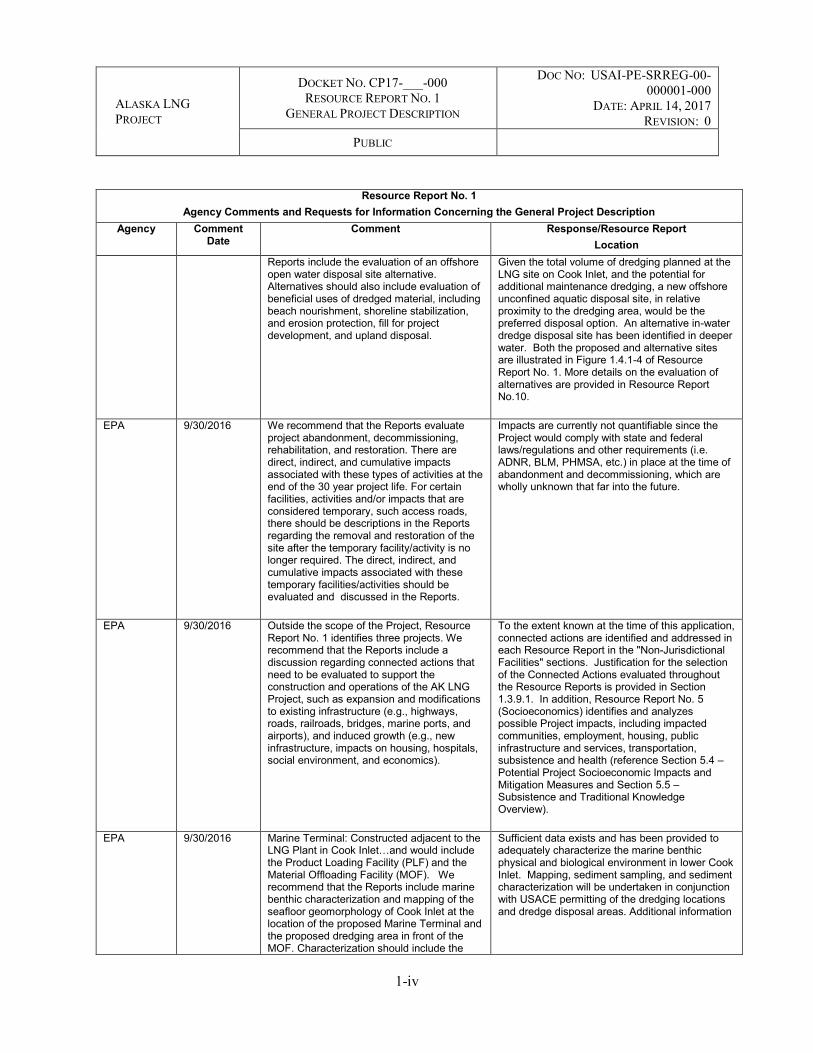
Reports include the evaluation of an offshore open water disposal site alternative. Alternatives should also include evaluation of beneficial uses of dredged material, including beach nourishment, shoreline stabilization, and erosion protection, fill for project development, and upland disposal.
Given the total volume of dredging planned at the LNG site on Cook Inlet, and the potential for additional maintenance dredging, a new offshore unconfined aquatic disposal site, in relative proximity to the dredging area, would be the preferred disposal option. An alternative in-water dredge disposal site has been identified in deeper water. Both the proposed and alternative sites are illustrated in Figure 1.4.1-4 of Resource Report No. 1. More details on the evaluation of alternatives are provided in Resource Report No.10.
EPA 9/30/2016 We recommend that the Reports evaluate project abandonment, decommissioning, rehabilitation, and restoration. There are direct, indirect, and cumulative impacts associated with these types of activities at the end of the 30 year project life. For certain facilities, activities and/or impacts that are considered temporary, such access roads, there should be descriptions in the Reports regarding the removal and restoration of the site after the temporary facility/activity is no longer required. The direct, indirect, and cumulative impacts associated with these temporary facilities/activities should be evaluated and discussed in the Reports.
Impacts are currently not quantifiable since the Project would comply with state and federal laws/regulations and other requirements (i.e. ADNR, BLM, PHMSA, etc.) in place at the time of abandonment and decommissioning, which are wholly unknown that far into the future.
EPA 9/30/2016 Outside the scope of the Project, Resource Report No. 1 identifies three projects. We recommend that the Reports include a discussion regarding connected actions that need to be evaluated to support the construction and operations of the AK LNG Project, such as expansion and modifications to existing infrastructure (e.g., highways, roads, railroads, bridges, marine ports, and airports), and induced growth (e.g., new infrastructure, impacts on housing, hospitals, social environment, and economics).
To the extent known at the time of this application, connected actions are identified and addressed in each Resource Report in the "Non-Jurisdictional Facilities" sections. Justification for the selection of the Connected Actions evaluated throughout the Resource Reports is provided in Section 1.3.9.1. In addition, Resource Report No. 5 (Socioeconomics) identifies and analyzes possible Project impacts, including impacted communities, employment, housing, public infrastructure and services, transportation, subsistence and health (reference Section 5.4 – Potential Project Socioeconomic Impacts and Mitigation Measures and Section 5.5 – Subsistence and Traditional Knowledge Overview).
EPA 9/30/2016 Marine Terminal: Constructed adjacent to the LNG Plant in Cook Inlet…and would include the Product Loading Facility (PLF) and the Material Offloading Facility (MOF). We recommend that the Reports include marine benthic characterization and mapping of the seafloor geomorphology of Cook Inlet at the location of the proposed Marine Terminal and the proposed dredging area in front of the MOF. Characterization should include the
Sufficient data exists and has been provided to adequately characterize the marine benthic physical and biological environment in lower Cook Inlet. Mapping, sediment sampling, and sediment characterization will be undertaken in conjunction with USACE permitting of the dredging locations and dredge disposal areas. Additional information

ALASKA LNG PROJECT
DOCKET NO. CP17-___-000 RESOURCE REPORT NO. 1
GENERAL PROJECT DESCRIPTION
DOC NO: USAI-PE-SRREG-00-000001-000
DATE: APRIL 14, 2017 REVISION: 0
PUBLIC
1-v
Resource Report No. 1 Agency Comments and Requests for Information Concerning the General Project Description
Agency Comment Date
Comment Response/Resource Report Location
seafloor geomorphology, the type of bottom surface substrate/sediments; epifauna and infauna; benthic invertebrates and communities – crustaceans, polychaetes, etc.; marine bottom fish and their distribution; and the location and distribution of rocky outcrops, submerged aquatic vegetation, such as eelgrass,
is provided throughout Resource Report Nos.2 and 3 on the existing environment.
EPA 9/30/2016 Product Loading Facility: The trestle would slope down from the top of bluff (+116 MLLW) to the berths (+50 MLLW). Due to the high erosion rates along the bluff, what, if any, temporary/permanent shoreline protection/armoring would be required to support the trestle for the marine terminal? We recommend including a description of engineering designs depicting how the bluff would be stabilized against erosion and sloughing to support the weight and structure of the trestle.
Other than where the MOF heavy haul road cuts through the bluff, which will require appropriate stabilization, the current plan is to minimize with the intent to eliminate any contact with the rest of the bluff so as to eliminate any need to implement an erosion control plan. The design of the Marine Terminal jetty is such that it will minimize any contact with the bluff and the 1-2 sets of piles that transition the bluff face and top of bluff will be designed to where the pile's structural integrity is not dependent on the presence of the bluff in the event that the bluff continues to slump and erode due to natural causes. Furthermore, the entire LNG plant has been moved sufficiently inland (e.g., east) to where bluff erosion and possible slumping due to earthquake activity is expected to have no detrimental impact on the facilities. This also works to minimize the visibility of the plant from the Cook Inlet and beach.
EPA 9/30/2016 Water Supply System – It is our understanding that AK LNG was planning to conduct aquifer pump tests from water wells in the Nikiski area to determine if water withdraw for construction and operations at the LNG plant site would affect the areas groundwater resources. We recommend that information be provided in the Reports regarding groundwater conditions. We encourage AK LNG to resume the pump tests next year.
Aquifer Pump Testing (APT) was conducted in 2016. Based on conditions encountered during well installation and water quality testing events, it became apparent that the previous selected well field location to a depth of 280 feet below grade, would not provide sufficient capacity nor adequate water quality to meet proposed LNG facility construction and operational project demands. Additional sources of water will be assessed prior to construction.
EPA 9/30/2016 Mainline MOF – We recommend that the Reports include a conceptual drawing of the location of the MOF on the west side of Cook Inlet, and the planned material laydown area and access roads. We recommend revising Figure 1.3.1-3.to show the location or the Mainline MOF structure on an aerial photo depicting the bathymetric elevations.
Comment acknowledged. Figures have been updated accordingly.
EPA 9/30/2016 West Dock - the 650-ft causeway breach between DH2 and DH3 would require use of temporary barge bridges ballasted to the seafloor to transport the GTP modules. What is being proposed to transport the modules
The Applicant will address this comment prior to the initiation of the EIS process.

ALASKA LNG PROJECT
DOCKET NO. CP17-___-000 RESOURCE REPORT NO. 1
GENERAL PROJECT DESCRIPTION
DOC NO: USAI-PE-SRREG-00-000001-000
DATE: APRIL 14, 2017 REVISION: 0
PUBLIC
1-vi
Resource Report No. 1 Agency Comments and Requests for Information Concerning the General Project Description
Agency Comment Date
Comment Response/Resource Report Location
across the 150-ft breach between DH 3 and the STP? Will there be a permanent solid fill with culverts or temporary barge bridges, as well? We recommend discussing this in more detail in the Reports.
EPA 9/30/2016 Induced Growth/Indirect Land Use Effects - How will the Reports evaluate “Induced Growth/Indirect Land Use Effects” from the construction of this project? Induced growth includes growth that would not have had occurred otherwise if the project were not constructed. Induced growth should considers things, such as new infrastructure - roads, highways, airports, housing, schools, hospitals, etc. and other reasonably foreseeable indirect and cumulative effects.
Cumulative impacts are addressed in Resource Report No. 1, Appendix L, following the Council on Environmental Quality's (CEQ) 1997 guidance manual Considering Cumulative Effects under NEPA. The topics of Induced Growth and Indirect Land Use are outside the scope of the CEQ manual. Resource Report No. 1, Appendix L, addresses both projects that will be accomplished by others that this Project will benefit from, as well as projects unrelated to Alaska LNG. Only projects that are permitted, in permitting, or have been announced as being viable were addressed. Other developments that may or may not occur are presently undefined and potential impacts were not evaluated because they are speculative. Such projects would be evaluated through their own environmental permitting process, which would include consideration nearby activities such as the Alaska LNG Project.
EPA 9/30/2016 Gas Interconnection Point Facilities – The Reports indicate that along the mainline pipeline route, there would be at least five gas interconnection points to allow for future in-state deliveries of natural gas. Three approximate locations of the gas interconnection points have been tentatively identified to serve the Fairbanks area, the Matanuska-Susitna Valley and Anchorage, and the Kenai Peninsula. We recommend that a fourth gas interconnection point be considered along the mainline pipeline to allow for future use of natural gas in and/or near the Park boundaries. Natural gas would support existing public and private businesses and facilities, and future development near the Park entrance and visitors center, and within the Park boundaries.
The Applicant will address this comment prior to the issuance of the DEIS.
EPA 9/30/2016 Material Offloading Facility (MOF) – at this time, what is the expected volume (cubic yards) of dredged material? We recommend identification of alternative areas for dredging and offshore disposal of dredged materials in Cook Inlet. We recommend providing the locations of alternative offshore disposal sites on a map.
The expected volume of dredged material required for construction and maintenance at the MOF is provided in Resource Report No. 1, Section 1.5.2.2.1.16. The estimated dredge volume for the Marine Terminal totals approximately 800,000 cubic yards, which includes: 165,000 cubic yards for MOF foundation preparation (conducted over two construction seasons); 492,000 cubic yards for dredging of the MOF berths to -30 MLLW and the approach to -32

ALASKA LNG PROJECT
DOCKET NO. CP17-___-000 RESOURCE REPORT NO. 1
GENERAL PROJECT DESCRIPTION
DOC NO: USAI-PE-SRREG-00-000001-000
DATE: APRIL 14, 2017 REVISION: 0
PUBLIC
1-vii
Resource Report No. 1 Agency Comments and Requests for Information Concerning the General Project Description
Agency Comment Date
Comment Response/Resource Report Location
feet MLLW (conducted over one construction season); and 143,000 cubic yards of over-dredge tolerance for MOF berths and approach. Additionally, approximately 140,000 cubic yards of maintenance dredging is expected to be necessary at the MOF berths and approach during the later construction seasons. Alternative in-water and/or nearshore placement locations Section 10.6.4.1.3. Alternative locations discussed include existing and new locations that would require permitting.
EPA 9/30/2016 We recommend that additional plans include the following: Marine Mammal Protection Plan; Water Withdrawal Plan; Hydrostatic Testing Plan; Archaeological and Cultural Resources Protection Plan; Subsistence Protection Plan; EPCRA (Emergency Planning and Community Right-to-Know Act) Plan; Oil Discharge and Prevention Contingency Plan (ODPCP); Facility Response Plans; Dredge Material and Disposal Plan; Closure, Abandonment and Rehabilitation Plan; Revegetation Plan, etc.
Mitigation plans are listed in their respective resource report. See Resource Reports Nos. 2-9; dredge material and disposal plans would be developed in conjunction with permitting; closure plans are not required nor applicable at this stage of the Project; and the restoration plan is included in Resource Report No. 3. Appendix C of this Resource Report indicates the permits and reviews required for this Project.
EPA 9/30/2016 Offshore Pipeline Construction - The Reports should include marine benthic characterization and mapping of the seafloor geomorphology of Cook Inlet along the Mainline pipeline right-of-way. Characterization should include the seafloor geomorphology, the type of bottom surface substrate/sediments; epifauna and infauna; benthic invertebrates and communities – crustaceans, polychaetes, etc.; marine bottom fish and their distribution; and the location and distribution of rocky outcrops, submerged aquatic vegetation, such as eelgrass, etc..
Benthic communities: Benthic communities for the area near the Offshore Pipeline are described in Resource Report No. 3, Section 3.4.8.1 and 3.4.8.2.2. Seafloor mapping, bottom surface substrate, rocky outcrops: A geophysical and geotechnical investigation along the Cook Inlet crossing is included in Resource Report No. 6, Appendix C, Summary of Geophysical and Geotechnical Surveys, Appendix A Pipeline Marine Shallow Geotechnical Report. The referenced report includes seafloor bathymetry and soil conditions. Detailed geophysical mapping of the final pipeline route across Cook Inlet would be accomplished in support of the State Lease and USACE permitting prior to construction. Marine bottom fish and their distribution: Information on marine fish in the vicinity of the Cook Inlet pipeline crossing are described Resource Report No. 3 Section 3.2.4. Eelgrass: This is addressed in the comment response section of Resource Report No. 3.

ALASKA LNG PROJECT
DOCKET NO. CP17-___-000 RESOURCE REPORT NO. 1
GENERAL PROJECT DESCRIPTION
DOC NO: USAI-PE-SRREG-00-000001-000
DATE: APRIL 14, 2017 REVISION: 0
PUBLIC
1-viii
Resource Report No. 1 Agency Comments and Requests for Information Concerning the General Project Description
Agency Comment Date
Comment Response/Resource Report Location
EPA 9/30/2016 MOF at Beluga – We recommend that the Reports include additional information regarding the proposed MOF at Beluga and proposed dredging locations, area, volumes, and location of dredge material disposal.
Resource Report No. 1 has been revised throughout Section 1.3.2 to include additional information on the Beluga MOF.
EPA 9/30/2016 Prudhoe Bay – We recommend providing the locations of alternative offshore disposal sites in Prudhoe Bay on a map. We recommend that the Reports include marine benthic characterization and mapping of the seafloor geomorphology of Prudhoe Bay at the locations of (1) the proposed dredge material disposal sites and (2) the proposed dredging area for the navigational channel and the turning basin in front of the proposed DH4. We recommend that characterization include the seafloor geomorphology, the type of bottom surface substrate/sediments; epifauna and infauna; benthic invertebrates and communities – crustaceans, polychaetes, etc.; marine bottom fish and their distribution; and the location and distribution of rocky outcrops, submerged aquatic vegetation, such as eelgrass, etc. We recommend that the Reports include a map depicting the location of the sediment sampling sites at West Dock. If additional trench studies and sampling sites are needed near the face of the proposed DH4, include the additional data and information in the Reports and include the sample site locations to the map.
Section 1.5.2.4.2 – West Dock Modifications and Dredging, has been changed to clarify that no offshore dredging disposal sites are proposed in Prudhoe Bay. No dredging is planned near DH4 (including the navigation channel or turning basin). Maps showing sediment sampling sites are included as Figure 2.3.1-9 in Resource Report No. 2.
EPA 9/30/2016 Ballast Water - In addition to LNGC’s, we recommend that the Reports include estimates of ballast water discharges from other commercial vessels that would be used during project construction and operation and identify the number of commercial vessels and the individual and cumulative volume of ballast water discharge into Cook Inlet and Prudhoe Bay. We recommend including a commitment by AK LNG to utilize commercial vessels (regardless of whether the vessel is foreign or U.S. flagged) that comply with Federal and State requirements for ballast water discharges, such as the EPA Vessel GP, USCG Ballast Water management program requirements, and the State’s ODPCP.
At this time, the applicant does not know the specific vessels that will be used as this will be up to the EPC. However, the Project knows the general types of vessels (e.g., module carriers and GHLS) that will be used to deliver modules and the approximate number and timing of shipments relative to the schedule. Also known are the tonnage, and the ballast water will be approximately equal to the tonnage being shipped, so an estimate of the amount of ballast water in whatever units are desired can be provided. This information is in the LNG Basis of Design. All vessels will be commercial vessels that are obligated to follow applicable codes and standards.
EPA 9/30/2016 Future Plans and Abandonment - The Reports should evaluate project abandonment, decommissioning, rehabilitation, restoration, etc. There are
Impacts are currently not quantifiable since the Project would comply with state and federal laws/regulations and other requirements (i.e. ADNR, BLM, PHMSA, etc.) in place at the time of

ALASKA LNG PROJECT
DOCKET NO. CP17-___-000 RESOURCE REPORT NO. 1
GENERAL PROJECT DESCRIPTION
DOC NO: USAI-PE-SRREG-00-000001-000
DATE: APRIL 14, 2017 REVISION: 0
PUBLIC
1-ix
Resource Report No. 1 Agency Comments and Requests for Information Concerning the General Project Description
Agency Comment Date
Comment Response/Resource Report Location
direct, indirect, and cumulative impacts associated with these types of activities at the end of the project life. Please specify the rationale why the Reports do not evaluate actions/impacts at the end of the 30 year life of the project. For certain facilities, we recommend that activities and/or impacts considered “temporary,” such as the MOF and access roads, etc., there should be descriptions in the Reports on the removal and restoration of the site after the “temporary” facility/activity is no longer required. We recommend that the direct, indirect, and cumulative impacts associated with these “temporary” facilities/activities should be evaluated and discussed in the Reports
abandonment and decommissioning, which are wholly unknown that far into the future.
EPA 9/30/2016 We recommend including MPRSA Section 102 under EPA permit or plan for transportation of dredged material for ocean disposal.
The basis for dredge disposal in Cook Inlet does not contemplate disposal in Federal waters, therefore this statute would not apply to the Project.
EPA 9/30/2016 The SPPC Plan requirement is located with NMFS/USFWS. We recommend including to section under EPA after FRP – Page 11 of 44.
Comment acknowledged. The SPCC Plan has been moved to below the Facility Response Plan in Appendix C.
EPA 9/30/2016 For EPA Plans, we recommend including the EPCRA Plan – Emergency Planning and Community Right-to-Know Act (EPCRA)
The Project will comply with PHMSA and FERC requirements for community involvement and notifications during operations.
EPA 9/30/2016 For EPA, we recommend including the CWA Section 402
EPA’s issuance of permits under CWA Section 402 has been added. Also, the following text has been added under "Alaska Construction General Permit (CGP); ADEC, Division of Water": ADEC has assumed permitting authority under CWA Section 402 for NPDES permit issuance except for certain permits and lands.
EPA 9/30/2016 For ADEC, we recommend including Ocean Discharge Prevention Contingency Plan (ODPCP)
We suspect the reviewer is referring to the Oil Discharge Prevention Contingency Plan. The Oil Discharge Prevention Contingency Plan is included in Appendix C for ADEC.
EPA 9/30/2016 Trestle Foundation along bluff. What additional structural supports are need to reinforce and stabilize the bluff and prevent erosion?
The only objects penetrating the bluff face and top of the bluff will be the vertical piles for no more than 2 of the 120-foot spans. The piles penetrating the bluff will be installed in the least disturbing manner (piled/driven or drilled and grouted). They will be installed to a depth such that is the bluff were to sluff or erode, the residual structural stability would be sufficient to support the trestle. No more that 1-2 sets or piles would be installed in the tidal zone and beach, and the

ALASKA LNG PROJECT
DOCKET NO. CP17-___-000 RESOURCE REPORT NO. 1
GENERAL PROJECT DESCRIPTION
DOC NO: USAI-PE-SRREG-00-000001-000
DATE: APRIL 14, 2017 REVISION: 0
PUBLIC
1-x
Resource Report No. 1 Agency Comments and Requests for Information Concerning the General Project Description
Agency Comment Date
Comment Response/Resource Report Location
120-foot span and height should be sufficient to not inhibit beach access.
EPA 9/30/2016 Missing Drawings: Layout plans for the GTP, LNG Plant; West Dock designs for DH4, dredging profiles, turning basin, ballast barge bridge layout; layout for the gravel mine sites, water reservoir, staging pads, new haul roads, operations center and camp.
Layout plans are provided on Resource Report No. 1, Appendix B. Typical drawings of the granular material mining sites are not included and will be provided in subsequent permit applications. The Applicant will provide information related to drawings prior to the initiation of the EIS process.
EPA 9/30/2016 We recommend including in the Reports reference the CEQ Guidance on evaluating Cumulative Impacts: Considering Cumulative Effects Under the National Environmental Policy Act (January 1997). Scope of cumulative impact assessment should be based on this guidance.
CEQ's publication "Considering Cumulative Effects Under the National Environmental Policy Act" (January 1997) is referenced in Resource Report No. 1, Appendix L.
EPA 9/30/2016 Spatial Scale - The geographic scale of the AK LNG Project encompasses the entire state of Alaska. The logistics of construction, operations and maintenance would require transportation by air, land and ocean transportation of cargo, fuel, LNG, personnel, etc. The scope of this project would include the Lower 48 states, Alaska, and potentially the pacific rim, and international countries. How should the geographic scale of the Area of Interest (AOI) for the cumulative impacts analysis be defined? We recommend that there should be a formal analysis/process to evaluate the AOI. What criteria would be used to evaluate the appropriate geographic scale for the AOI? We recommend the Reports address these questions.
The Area of Interest is defined in Section 1.1.1 of Appendix L, Resource Report No. 1 in accordance with available guidance from CEQ and FERC. The geographic scale of the Project does not encompass the entire State of Alaska. The Area of Interest will be discussed with FERC and the cooperating agencies during development of the Environmental Impact Statement.
EPA 9/30/2016 Temporal Scale - The temporal scale being considered for this analysis includes projects taking place from 2019 to 2026 (start of construction to full production). We recommend that the CEA also be extended 30 years within the Projects’ operations to address reasonable foreseeable future actions, which would be to 2056. How would this timeframe address “past and present” actions? How far back in the timeline should past and present actions be evaluated – 10, 20, or 30 years? Starting the analysis in 2009, 1999, or 1989? How should the temporal scale of the AOI for cumulative impacts analysis be defined? We recommend that Reports include a formal analysis/
CEQ's publication "Considering Cumulative Effects Under the National Environmental Policy Act" (January 1997) is included in the document by reference in the text of Section 1.0, Resource Report No. 1, Appendix L and included in the list of References in Section 6.0, Resource Report No. 1, Appendix L.

ALASKA LNG PROJECT
DOCKET NO. CP17-___-000 RESOURCE REPORT NO. 1
GENERAL PROJECT DESCRIPTION
DOC NO: USAI-PE-SRREG-00-000001-000
DATE: APRIL 14, 2017 REVISION: 0
PUBLIC
1-xi
Resource Report No. 1 Agency Comments and Requests for Information Concerning the General Project Description
Agency Comment Date
Comment Response/Resource Report Location
process to evaluate the AOI. What criteria would be used to evaluate the appropriate temporal scale for the AOI? We recommend that the Reports address these questions. We recommend referring to CEQ Guidance (June 24, 2005) Guidance on the Consideration of Past Actions in CEA.
EPA 9/30/2016 A list of the identified reasonably foreseeable future projects within the AOI is provided in Table 1… This list is quite exhaustive and lengthy, but may require additional other projects. We recommend that there should be a thoughtful process to screen reasonable foreseeable future projects from this list. Specific criteria should be developed to use as filters, rather than listing certain projects to be included/excluded.
The Applicant will address this comment prior to the issuance of the DEIS. AGDC will discuss with FERC the recommended approach described in Resource Report No.1, Section 1.1.2 Project Selection Criteria and Methodology, Appendix L.
FERC 10/26/2016 Commitments were made by AKLNG in the resource report as information to be provided or pending in response to previous comments made by FERC or other agencies. If the information will not be included in the application as indicated by Alaska LNG, provide a schedule for when it will be filed with FERC or to the requesting agency as applicable. a. A full assessment of the potential projects required to facilitate the use of Alaska Department of Transportation and Public Facilities’ (ADOT&PF) facilities, including airstrip and highway projects and improvements. (Agency Comments and Requests for Information Concerning General Project Description table, pages 1-ii, 1-viii, and 1-ix)
The Applicant will address State of Alaska agency comments during the State permitting processes and timeframes.
FERC 10/26/2016 Commitments were made by AKLNG in the resource report as information to be provided or pending in response to previous comments made by FERC or other agencies. If the information will not be included in the application as indicated by Alaska LNG, provide a schedule for when it will be filed with FERC or to the requesting agency as applicable. b. Documentation of consultation with ADOT&PF regarding the Project’s potential impacts of the use of public roads and airstrip facilities. (Agency Comments and Requests for Information Concerning General Project Description table, pages 1-viii)
The Applicant will address State of Alaska agency comments during the State permitting processes and timeframes.

ALASKA LNG PROJECT
DOCKET NO. CP17-___-000 RESOURCE REPORT NO. 1
GENERAL PROJECT DESCRIPTION
DOC NO: USAI-PE-SRREG-00-000001-000
DATE: APRIL 14, 2017 REVISION: 0
PUBLIC
1-xii
Resource Report No. 1 Agency Comments and Requests for Information Concerning the General Project Description
Agency Comment Date
Comment Response/Resource Report Location
FERC 10/26/2016 Commitments were made by AKLNG in the resource report as information to be provided or pending in response to previous comments made by FERC or other agencies. If the information will not be included in the application as indicated by Alaska LNG, provide a schedule for when it will be filed with FERC or to the requesting agency as applicable. c. A full assessment of potential Project impacts on human / bear and fox interactions, including a literature review on the efforts developed through the years of Trans-Alaska Pipeline System (TAPS) and other project experiences as well as a comprehensive Wildlife Avoidance and Interaction Plan. (Agency Comments and Requests for Information Concerning General Project Description table, pages 1-iii)
The Applicant will address State of Alaska agency comments during the State permitting processes and timeframes.
FERC 10/26/2016 Commitments were made by AKLNG in the resource report as information to be provided or pending in response to previous comments made by FERC or other agencies. If the information will not be included in the application as indicated by Alaska LNG, provide a schedule for when it will be filed with FERC or to the requesting agency as applicable. d. Gravitational collapse faults and low activity faults exist in the general vicinity of the Point Thomson Gas Transmission Line (PTTL). A Geologic Study will be provided that addresses whether or not these features cross any of the PTTL facilities or pipelines. (Agency Comments and Requests for Information Concerning General Project Description table, pages 1-vi)
No study is required for the Point Thomson Gas Transmission Line (PTTL) to assess gravitational faults. The risk to the pipeline from such a feature is minor, and accommodated in the design of an aboveground pipeline similar to the other existing pipelines built through the North Slope.
FERC 10/26/2016 Commitments were made by AKLNG in the resource report as information to be provided or pending in response to previous comments made by FERC or other agencies. If the information will not be included in the application as indicated by Alaska LNG, provide a schedule for when it will be filed with FERC or to the requesting agency as applicable. e. A full assessment of project Construction Logistics Plan that includes information as requested by ADOT&PF on the locations where pipeline would cross an ADOT&PF road and or be longitudinal within the ADOT&PF highway right-of-way. Include what existing bridges, if any, the pipeline proposes to use or attach its pipeline. Also, include material sources to be used, locations of laydown yards, camps, etc. and proposed
The PTTL crossing of the West Channel of the Sagavanirktok River would be by adding structural extensions to an existing pipeline bridge. The Applicant will address this comment prior to the initiation of the EIS process.

ALASKA LNG PROJECT
DOCKET NO. CP17-___-000 RESOURCE REPORT NO. 1
GENERAL PROJECT DESCRIPTION
DOC NO: USAI-PE-SRREG-00-000001-000
DATE: APRIL 14, 2017 REVISION: 0
PUBLIC
1-xiii
Resource Report No. 1 Agency Comments and Requests for Information Concerning the General Project Description
Agency Comment Date
Comment Response/Resource Report Location
access points to the existing highway system. (Agency Comments and Requests for Information Concerning General Project Description table, pages 1-vi) `
FERC 10/26/2016 Commitments were made by AKLNG in the resource report as information to be provided or pending in response to previous comments made by FERC or other agencies. If the information will not be included in the application as indicated by Alaska LNG, provide a schedule for when it will be filed with FERC or to the requesting agency as applicable. f. A description of the owner/operator of each facility. (Agency Comments and Requests for Information Concerning General Project Description table, pages 1-xi)
Owner/operators are named in Resource Report No. 1, Section 1, Project Description.
FERC 10/26/2016 Commitments were made by AKLNG in the resource report as information to be provided or pending in response to previous comments made by FERC or other agencies. If the information will not be included in the application as indicated by Alaska LNG, provide a schedule for when it will be filed with FERC or to the requesting agency as applicable. g. Information regarding blast rock and construction debris disposal locations. (Agency Comments and Requests for Information Concerning General Project Description table, pages 1-xii)
Disposal locations for blast rock included in the Gravel Plan in Resource Report No. 6.
FERC 10/26/2016 Commitments were made by AKLNG in the resource report as information to be provided or pending in response to previous comments made by FERC or other agencies. If the information will not be included in the application as indicated by Alaska LNG, provide a schedule for when it will be filed with FERC or to the requesting agency as applicable. h. Information regarding location, acreage, and access to pipe and concrete coating yard(s). Include how locations will obtain utilities and water. (Agency Comments and Requests for Information Concerning General Project Description table, pages 1-xiii; section 1.3.2.4, page 1-43)
Resource Report No.1 Section 1.3.2.4 was revised to explain that pipe coating yard location(s) are anticipated to be within developed areas with access to commercial utilities. Any utilities not available commercially will be developed by the project.
FERC 10/26/2016 Commitments were made by AKLNG in the resource report as information to be provided or pending in response to previous comments made by FERC or other agencies. If the information will not be included in the application as indicated by Alaska LNG,
The Applicant has prepared an Essential Fish Habitat Assessment (see Appendix D of Resource Report No. 3).

ALASKA LNG PROJECT
DOCKET NO. CP17-___-000 RESOURCE REPORT NO. 1
GENERAL PROJECT DESCRIPTION
DOC NO: USAI-PE-SRREG-00-000001-000
DATE: APRIL 14, 2017 REVISION: 0
PUBLIC
1-xiv
Resource Report No. 1 Agency Comments and Requests for Information Concerning the General Project Description
Agency Comment Date
Comment Response/Resource Report Location
provide a schedule for when it will be filed with FERC or to the requesting agency as applicable. i. An Essential Fish Habitat Assessment that incorporates comments from agencies. (Agency Comments and Requests for Information Concerning General Project Description table, page 1-xvii)
FERC 10/26/2016 Commitments were made by AKLNG in the resource report as information to be provided or pending in response to previous comments made by FERC or other agencies. If the information will not be included in the application as indicated by Alaska LNG, provide a schedule for when it will be filed with FERC or to the requesting agency as applicable. j. A final Waste Management Plan that incorporates comments from the Alaska Department of Fish and Game and U.S. Fish and Wildlife Service on deterrent measures for wildlife. (Agency Comments and Requests for Information Concerning General Project Description table, page 1-xxiii)
Meeting minutes and a table of agency comments on the Waste Management Plan are incorporated into the updated version found in Resource Report No. 8.
FERC 10/26/2016 Commitments were made by AKLNG in the resource report as information to be provided or pending in response to previous comments made by FERC or other agencies. If the information will not be included in the application as indicated by Alaska LNG, provide a schedule for when it will be filed with FERC or to the requesting agency as applicable. k. A Restoration Plan that describes rehabilitation approaches and outlines performance criteria and timelines required by regulatory agencies. (Agency Comments and Requests for Information Concerning General Project Description table, page 1-xxv)
A draft Restoration Plan is provided as Appendix P to Resource Report No. 3. The purpose of the draft Restoration Plan is to summarize the goals and objectives of the Alaska LNG Project restoration effort for the Mainline pipeline (Mainline) trench and associated right-of-way (ROW) and the various site preparation and plant cultivation techniques that may be employed to achieve the goals and objectives. The performance standards for achieving successful restoration would be developed in collaboration with the appropriate federal, state, and local regulatory agencies and landowners. The Project will work with the appropriate federal, state, and local regulatory agencies and landowners through the development of the EIS to receive input to finalize the Restoration Plan.
FERC 10/26/2016 Commitments were made by AKLNG in the resource report as information to be provided or pending in response to previous comments made by FERC or other agencies. If the information will not be included in the application as indicated by Alaska LNG, provide a schedule for when it will be filed with FERC or to the requesting agency as applicable. l. An updated description of the Project’s footprint that includes helipads and airstrips that would require improvements to existing facilities as well as additional details concerning construction disposal locations, communication towers, height of structures,
The Project footprint has been updated, including helipads and disposal sites. Additional features such as communication towers, power lines, fuel storage locations, site security equipment and other facilities will be provided prior to construction. Note that none of these features will be outside the footprint provided in the FERC application.
ALASKA LNG PROJECT
DOCKET NO. CP17-___-000 RESOURCE REPORT NO. 1
GENERAL PROJECT DESCRIPTION
DOC NO: USAI-PE-SRREG-00-000001-000
DATE: APRIL 14, 2017 REVISION: 0
PUBLIC
1-xv
Resource Report No. 1 Agency Comments and Requests for Information Concerning the General Project Description
Agency Comment Date
Comment Response/Resource Report Location
powerlines, fuel and hazardous material storage locations, site security equipment, and other facilities. (Agency Comments and Requests for Information Concerning General Project Description table, pages 1-xxxiii and 1-lxii; section 1.3.6, page 1-75 and section 1.4.2.3.3, page 1-105)
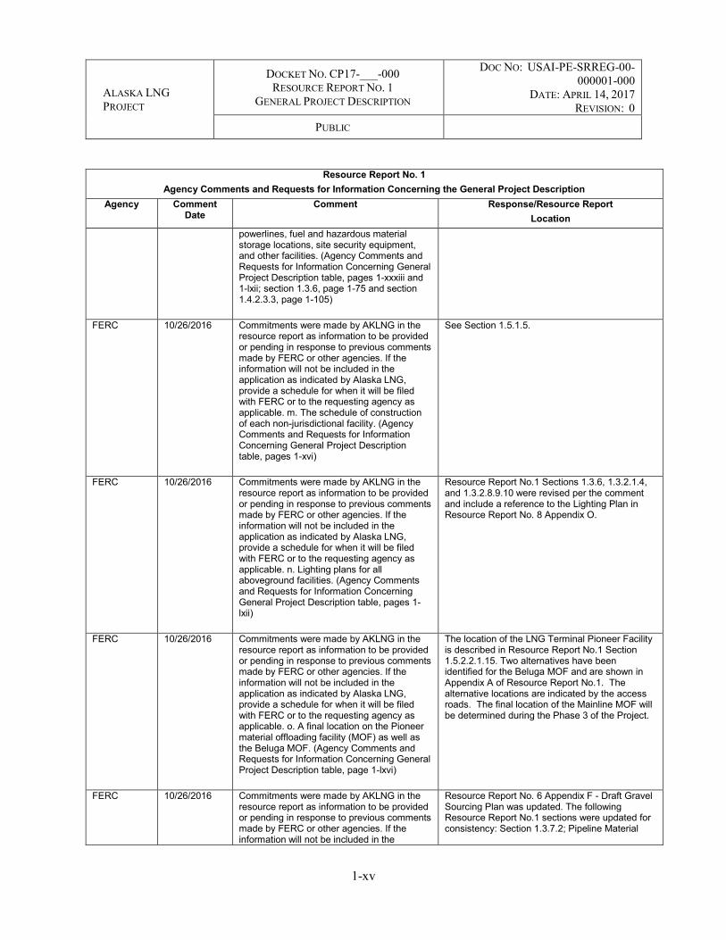
FERC 10/26/2016 Commitments were made by AKLNG in the resource report as information to be provided or pending in response to previous comments made by FERC or other agencies. If the information will not be included in the application as indicated by Alaska LNG, provide a schedule for when it will be filed with FERC or to the requesting agency as applicable. m. The schedule of construction of each non-jurisdictional facility. (Agency Comments and Requests for Information Concerning General Project Description table, pages 1-xvi)
See Section 1.5.1.5.
FERC 10/26/2016 Commitments were made by AKLNG in the resource report as information to be provided or pending in response to previous comments made by FERC or other agencies. If the information will not be included in the application as indicated by Alaska LNG, provide a schedule for when it will be filed with FERC or to the requesting agency as applicable. n. Lighting plans for all aboveground facilities. (Agency Comments and Requests for Information Concerning General Project Description table, pages 1-lxii)
Resource Report No.1 Sections 1.3.6, 1.3.2.1.4, and 1.3.2.8.9.10 were revised per the comment and include a reference to the Lighting Plan in Resource Report No. 8 Appendix O.
FERC 10/26/2016 Commitments were made by AKLNG in the resource report as information to be provided or pending in response to previous comments made by FERC or other agencies. If the information will not be included in the application as indicated by Alaska LNG, provide a schedule for when it will be filed with FERC or to the requesting agency as applicable. o. A final location on the Pioneer material offloading facility (MOF) as well as the Beluga MOF. (Agency Comments and Requests for Information Concerning General Project Description table, page 1-lxvi)
The location of the LNG Terminal Pioneer Facility is described in Resource Report No.1 Section 1.5.2.2.1.15. Two alternatives have been identified for the Beluga MOF and are shown in Appendix A of Resource Report No.1. The alternative locations are indicated by the access roads. The final location of the Mainline MOF will be determined during the Phase 3 of the Project.
FERC 10/26/2016 Commitments were made by AKLNG in the resource report as information to be provided or pending in response to previous comments made by FERC or other agencies. If the information will not be included in the
Resource Report No. 6 Appendix F - Draft Gravel Sourcing Plan was updated. The following Resource Report No.1 sections were updated for consistency: Section 1.3.7.2; Pipeline Material
ALASKA LNG PROJECT
DOCKET NO. CP17-___-000 RESOURCE REPORT NO. 1
GENERAL PROJECT DESCRIPTION
DOC NO: USAI-PE-SRREG-00-000001-000
DATE: APRIL 14, 2017 REVISION: 0
PUBLIC
1-xvi
Resource Report No. 1 Agency Comments and Requests for Information Concerning the General Project Description
Agency Comment Date
Comment Response/Resource Report Location
application as indicated by Alaska LNG, provide a schedule for when it will be filed with FERC or to the requesting agency as applicable. p. Updated Gravel Sourcing Plan and Site Reclamation Measures that includes sources and reclamation measures. (Agency Comments and Requests for Information Concerning General Project Description table, pages 1-vi)
Sites, 1.3.7.3 GTP Material Site, and 1.3.7.3.1 Mine Site.
FERC 10/26/2016 Commitments were made by AKLNG in the resource report as information to be provided or pending in response to previous comments made by FERC or other agencies. If the information will not be included in the application as indicated by Alaska LNG, provide a schedule for when it will be filed with FERC or to the requesting agency as applicable. q. Complete the Application using most recent centerline and update construction workspace layout (we are aware of at least a Rev. C). (Agency Comments and Requests for Information Concerning General Project Description table, pages 1-1xii; section 1.3.2.4, page 1-42)
The most current revision of the alignment is Rev C2. This alignment and associated footprint is what has been used for this version of the Resource Reports.
FERC 10/26/2016 Commitments were made by AKLNG in the resource report as information to be provided or pending in response to previous comments made by FERC or other agencies. If the information will not be included in the application as indicated by Alaska LNG, provide a schedule for when it will be filed with FERC or to the requesting agency as applicable. r. Joint study commissioned with Alaska Police Standards Council to evaluate any impacts on TAPS in areas where the proposed Mainline would be in proximity. (Agency Comments and Requests for Information Concerning General Project Description table, pages 1-lxix)
The general approach for crossing TAPS has been coordinated with the TAPS operator, Alyeska Pipeline Service Company (APSC). See Resource Report No. 11, Section 11.7.2.7.4 for information on the TAPS Impact Study. The has resulted in 9 separate study reports which are included as an attachment to Resource Report No. 11.
FERC 10/26/2016 Commitments were made by AKLNG in the resource report as information to be provided or pending in response to previous comments made by FERC or other agencies. If the information will not be included in the application as indicated by Alaska LNG, provide a schedule for when it will be filed with FERC or to the requesting agency as applicable. s. A comparison of FERC’s Upland Erosion Control, Revegetation, and Maintenance Plan (Plan) and Wetland and Waterbody Construction and Mitigation Procedures (Procedures) to the Project’s proposed Plan and Procedures. (Agency
Resource Report No. 7, Appendix D “Upland Erosion Control, Revegetation, and Maintenance Plan. (Alaska LNG Plan)” is based on the FERC “Upland Erosion Control, Revegetation, and Maintenance Plan” of May 2013, with project specific edits, differences or additions marked in red font.

ALASKA LNG PROJECT
DOCKET NO. CP17-___-000 RESOURCE REPORT NO. 1
GENERAL PROJECT DESCRIPTION
DOC NO: USAI-PE-SRREG-00-000001-000
DATE: APRIL 14, 2017 REVISION: 0
PUBLIC
1-xvii
Resource Report No. 1 Agency Comments and Requests for Information Concerning the General Project Description
Agency Comment Date
Comment Response/Resource Report Location
Comments and Requests for Information Concerning General Project Description table, pages 1-xiv and 1-lxxiii)
FERC 10/26/2016 Commitments were made by AKLNG in the resource report as information to be provided or pending in response to previous comments made by FERC or other agencies. If the information will not be included in the application as indicated by Alaska LNG, provide a schedule for when it will be filed with FERC or to the requesting agency as applicable. t. Consultation with land managing agencies, state and local planning agencies, and other appropriate entities for the cumulative impact assessment. (Agency Comments and Requests for Information Concerning General Project Description table, pages 1-lxxiv).
The appropriate time for addressing this comment will be during the Draft EIS.
FERC 10/26/2016 Commitments were made by AKLNG in the resource report as information to be provided or pending in response to previous comments made by FERC or other agencies. If the information will not be included in the application as indicated by Alaska LNG, provide a schedule for when it will be filed with FERC or to the requesting agency as applicable.on as indicated by Alaska LNG, provide a schedule for when it will be filed with FERC or provided to the requesting agency as applicable. u. To minimize visual impacts, resource reports should describe measures that AKLNG would use to maintain a vegetative buffer along the Dalton Highway and other roadways or explanation why this is not feasible. This may include setting entry and exit bore/drill locations farther from the roadway than is typically done. (Agency Comments and Requests for Information Concerning General Project Description table, pages 1-lxxv)
This discussion is provided in Section 8.14 of Resource Report No. 8. Recommendations for mitigation include maintaining vegetative screens between Project sites and public spaces such as roads, and angling entry roads to camps and other sites so equipment and associated materials are not visible from public roads. Additional information on vegetative buffers and screens, including distances from roadways to reduce visual impacts, will be provided in the stipulations of the ROW Lease (DNR) and the federal Grant of ROW (BLM).
FERC 10/26/2016 Commitments were made by AKLNG in the resource report as information to be provided or pending in response to previous comments made by FERC or other agencies. If the information will not be included in the application as indicated by Alaska LNG, provide a schedule for when it will be filed with FERC or to the requesting agency as applicable. v. Milepost (MP) 169, Atigun Pass – resource reports should include a detailed work plan and assessment of impacts on Atigun Pass, including natural passage for wildlife, operation of the TAPS line, traffic
A detailed construction plan for Atigun Pass would be developed prior to construction once a construction contractor has been selected.

ALASKA LNG PROJECT
DOCKET NO. CP17-___-000 RESOURCE REPORT NO. 1
GENERAL PROJECT DESCRIPTION
DOC NO: USAI-PE-SRREG-00-000001-000
DATE: APRIL 14, 2017 REVISION: 0
PUBLIC
1-xviii
Resource Report No. 1 Agency Comments and Requests for Information Concerning the General Project Description
Agency Comment Date
Comment Response/Resource Report Location
management for the Dalton Highway, and geologic hazards (both natural and man-made). (Agency Comments & Requests for Information Concerning General Project Description table, pages 1-lxxv)
FERC 10/26/2016 Commitments were made by AKLNG in the resource report as information to be provided or pending in response to previous comments made by FERC or other agencies. If the information will not be included in the application as indicated by Alaska LNG, provide a schedule for when it will be filed with FERC or to the requesting agency as applicable. w. MPs 378 and 380 –In areas where there is little separation between TAPS and the planned Alaska LNG Mainline, Alaska LNG may need to prepare a special construction plan and go into greater detail regarding the methods to be used and how it would minimize the effect or risk to TAPS. (Agency Comments and Requests for Information Concerning General Project Description table, pages 1-lxxv)
The general approach for crossing TAPS has been coordinated with the TAPS operator, Alyeska Pipeline Service Company (APSC). See Resource Report No. 11, Section 11.7.2.7.4 for information on the TAPS Impact Study. The has resulted in 9 separate study reports which are included as an attachment to Resource Report No. 11.
FERC 10/26/2016 Commitments were made by AKLNG in the resource report as information to be provided or pending in response to previous comments made by FERC or other agencies. If the information will not be included in the application as indicated by Alaska LNG, provide a schedule for when it will be filed with FERC or to the requesting agency as applicable. x. MP 640.1 – road bore at this location and others like it should have sufficient setback on both sides of Parks Highway to minimize visual impact of the crossing. (Agency Comments and Requests for Information Concerning General Project Description table, pages 1-lxxvi)
The Applicant will address this comment after the FEIS but prior to construction start.
FERC 10/26/2016 Commitments were made by AKLNG in the resource report as information to be provided or pending in response to previous comments made by FERC or other agencies. If the information will not be included in the application as indicated by Alaska LNG, provide a schedule for when it will be filed with FERC or to the requesting agency as applicable. y. Site-specific crossing plans for locations where TAPS is crossed. (Agency Comments and Requests for Information Concerning General Project Description
Site-specific crossing plans will be provided prior to construction. Note pipeline routing was conducted such that all but one crossing of TAPS were located where TAPS is aboveground. Where AKLNG crosses the buried TAPS pipeline near Atigun pass, AKLNG will pass over TAPS in a buried mode with sufficient fill added over AKLNG to meet code required depth of cover. A typical drawing of a buried AKLNG pipeline passing under the aboveground TAPS pipeline can be found in Appendix E. A typical drawing of a buried AKLNG pipeline passing over the buried

ALASKA LNG PROJECT
DOCKET NO. CP17-___-000 RESOURCE REPORT NO. 1
GENERAL PROJECT DESCRIPTION
DOC NO: USAI-PE-SRREG-00-000001-000
DATE: APRIL 14, 2017 REVISION: 0
PUBLIC
1-xix
Resource Report No. 1 Agency Comments and Requests for Information Concerning the General Project Description
Agency Comment Date
Comment Response/Resource Report Location
table, pages 1-lxxxix and section 1.3.2.1.2, page 1-34)
TAPS pipeline near Atigun Pass can also be found in Appendix E.
FERC 10/26/2016 Commitments were made by AKLNG in the resource report as information to be provided or pending in response to previous comments made by FERC or other agencies. If the information will not be included in the application as indicated by Alaska LNG, provide a schedule for when it will be filed with FERC or to the requesting agency as applicable. z. Consideration of an employee shuttle bus system. (Agency Comments and Requests for Information Concerning General Project Description table, pages 1-xci)
Resource Report No.5 explains that workers would be shuttled from the camps to the project sites daily.
FERC 10/26/2016 Commitments were made by AKLNG in the resource report as information to be provided or pending in response to previous comments made by FERC or other agencies. If the information will not be included in the application as indicated by Alaska LNG, provide a schedule for when it will be filed with FERC or to the requesting agency as applicable. aa. Additional information regarding the condensate product volumes, disposition, and means of transport. (section 1.3.1.4.1. page 1-19)
Approximately 1,000 barrels per day of condensate removed from the natural gas stream by the liquefaction process would be distributed by truck (approximately five to six trucks per day) or potentially piped to a customer in the local vicinity of the LNG Plant. The condensate product would first be stored in a condensate storage tank. The truck loading system would include the equipment necessary for the safe and reliable handling and loading of condensate (e.g., pumps or lease automatic custody transfer (LACT) unit, truck loading facility, vapor handling, and disposal).
FERC 10/26/2016 Commitments were made by AKLNG in the resource report as information to be provided or pending in response to previous comments made by FERC or other agencies. If the information will not be included in the application as indicated by Alaska LNG, provide a schedule for when it will be filed with FERC or to the requesting agency as applicable. bb. Include the results of the analysis for the potential use of Homer Electric Association power and associated non-jurisdictional facilities during construction of the Liquefaction Facility. (section 1.3.1.5.4. page 1-24).
Resource Report No. 1, Section 1.3.1.3.9 and Section 1.3.1.5.4 include updated text for the results of the study to use power provided by Homer Electric Association. The initial power demand range during construction would be approximately 20 to 25 MW. Actual power requirements would vary as the construction activity fluctuates between the summer and winter months. Portable generators would be on site for both backup and active work (e.g., welding). The generators would have drip pans and containment. HEA would supply power during construction.
FERC 10/26/2016 Commitments were made by AKLNG in the resource report as information to be provided or pending in response to previous comments made by FERC or other agencies. If the information will not be included in the application as indicated by Alaska LNG, provide a schedule for when it will be filed with FERC or to the requesting agency as applicable. cc. Designs of these three buried crossings (i.e., Shaviovik River, Kadleroshilik
Three crossings (i.e., Shaviovik River, Kadleroshilik River, and Sagavanirktok River Main Channel) would be buried with conventional open-cut methods in the winter. Figures for each crossing are provided in Resource Report No. 2, Appendix I and a design study is provided as Appendix E of Resource Report No. 10.

ALASKA LNG PROJECT
DOCKET NO. CP17-___-000 RESOURCE REPORT NO. 1
GENERAL PROJECT DESCRIPTION
DOC NO: USAI-PE-SRREG-00-000001-000
DATE: APRIL 14, 2017 REVISION: 0
PUBLIC
1-xx
Resource Report No. 1 Agency Comments and Requests for Information Concerning the General Project Description
Agency Comment Date
Comment Response/Resource Report Location
River, and Sagavanirktok River Main Channel) on the PTTL. (section 1.3.2.3. page 1-40)
FERC 10/26/2016 Commitments were made by AKLNG in the resource report as information to be provided or pending in response to previous comments made by FERC or other agencies. If the information will not be included in the application as indicated by Alaska LNG, provide a schedule for when it will be filed with FERC or to the requesting agency as applicable. dd. Location and acreages for equipment fueling facilities, disposal sites for construction generated wastes and excavated material, stumps, blast rock, acid drainage rock, and slash removed from the permanent pipeline right- of-way. (section 1.3.2.4, page 1-42 and section 1.3.8.2, page 1-88)
Equipment fueling will occur anywhere within the construction ROW. All fueling activities will be in accordance with the permit stipulations. Equipment Fuel Storage Locations and projected volume of the required tankage are given in Section 1.3 of Resource Report No. 1. The Acreages of the equipment Fuel Storage Facilities are included in the construction footprint given in table 1.4-1. Disposal sites are shown in Appendix A of Resource Report No. 1.
FERC 10/26/2016 Commitments were made by AKLNG in the resource report as information to be provided or pending in response to previous comments made by FERC or other agencies. If the information will not be included in the application as indicated by Alaska LNG, provide a schedule for when it will be filed with FERC or to the requesting agency as applicable. ee. Evaluation of other potential take-off points including cost to take gas from the tap to the village/community, as well as documentation of discussions with local entities regarding plans to take the gas from the take-off points identified in the resource reports. (appendix L; section 1.3.2.1.3.4, page 1-39)
The Applicant will address this comment prior to the issuance of the DEIS.
FERC 10/26/2016 Commitments were made by AKLNG in the resource report as information to be provided or pending in response to previous comments made by FERC or other agencies. If the information will not be included in the application as indicated by Alaska LNG, provide a schedule for when it will be filed with FERC or to the requesting agency as applicable. ff. Documentation of consultation with land managing agencies, state and local planning agencies, and other appropriate entities to identify additional present and reasonably foreseeable future projects (e.g., roads, bridges, mining, large commercial/industrial/residential developments) in potential resource area of impact that could contribute to a cumulative
The appropriate time for addressing this comment will be during development of the Draft EIS.
ALASKA LNG PROJECT
DOCKET NO. CP17-___-000 RESOURCE REPORT NO. 1
GENERAL PROJECT DESCRIPTION
DOC NO: USAI-PE-SRREG-00-000001-000
DATE: APRIL 14, 2017 REVISION: 0
PUBLIC
1-xxi
Resource Report No. 1 Agency Comments and Requests for Information Concerning the General Project Description
Agency Comment Date
Comment Response/Resource Report Location
effect when considered with the effects of the Project. (appendix L, page 3)
FERC 10/26/2016 2. As required in Title 18 of the Code of Federal Regulations, Part 380.12(c) (18 CFR 380.12[c]), include the information identified below: a. Subpart (3)(i), show nonlinear construction areas on maps at a scale of 1:3,600 or larger, including the West Dock, GTP, Liquefaction Facility, camps, yards, and material sites. For drawings not provided at this scale, include justification for the scale used. (appendix A). b. Subpart (3)(ii), include original aerial images or photographs or alignment sheets that depict current land use with a scale of 1:6,000 or larger showing the purposed pipeline route and location of major aboveground facilities. For drawings not provided at this scale, include justification for the scale used. (appendix A)
Facilities are shown on both topo and aerial imagery. Layouts (footprint) for compressor stations and typical facility designs are included in Resource Report No. 1 Appendix E. Design plans for each location are not available. The limits of areas permanently disturbed are already depicted.
FERC 10/26/2016 2. As required in Title 18 of the Code of Federal Regulations, Part 380.12(c) (18 CFR 380.12[c]), include the information identified below: c. Subpart (4), include the plot plan of each compressor station on aerial imagery. Include the proposed facility plan, auxiliary buildings, access, and limits of areas that would be permanently disturbed. (appendix B). d. Subpart (6), describe and identify by milepost, construction and restoration methods proposed to be used where Project facilities will be installed in: i. areas of rugged topography; ii. residential areas (e.g., on the Kenai Peninsula between Boulder Point and the proposed Liquefaction Facility); iii. sites where the pipeline would be located parallel to and under roads; and iv. sites where explosives are likely to be used.
The Applicant will address subpart Part C prior to the initiation of the EIS process. Information related to Part d is provided in Appendix E (Typical Drawings), Appendix H (Specific Designs for Major Highway, Railroad, and TAPS crossings), and Appendix M (Pipeline Winter and Permafrost Construction Plan) of Resource Report No. 1. Additional information is also provided in Appendix N (Applicant’s Wetland and Waterbody Construction, and Mitigation Procedures) of Resource Report No. 2, Appendix B (Blasting Plan) of Resource Report No. 6, and Appendix D (Applicant’s Upland Erosion Control, Revegetation, and Maintenance Plan) of Resource Report No. 7. Further details will be provided after the FEIS but prior to construction start.
FERC 10/26/2016 2. In addition, given the Project’s location and unique environment, describe and identify by milepost the construction and restoration methods proposed to be used in the in the following areas: v. marine pipelay; vi. anadromous stream crossings; vii. steep terrain; viii. mass wasting (including avalanches, landslides, frozen debris lobes, and debris flows); ix. soil liquefaction; x. fault zones; xi. permafrost; xii. unstable longitudinal and cross slopes; xiii. frozen cross-slopes and side hill cuts; xiv. pingos and palsas, such as the terrain alongside Sukakpak Mountain where palsas appear
Marine pipeline - No unique measures for construction or restoration are required for laying the pipeline across Cook Inlet, similar to the dozens of pipelines already existing in Cook Inlet; Anadromous Stream crossings - working with ADF&G, Alaska LNG does not need to provide unique construction or restoration measures, methods provided in Resource Report No. 3 were developed with ADF&G review; Steep Terrain--measures for building the pipeline in steep terrain are the same as proposed in lower 48 projects, restoration will be as outlined in Resource Report No. 1 and the Project-specific Plans and Procedures; fault zones--site-specific plans will be developed for active faults in consultation with PHMSA prior to construction; permafrost--

ALASKA LNG PROJECT
DOCKET NO. CP17-___-000 RESOURCE REPORT NO. 1
GENERAL PROJECT DESCRIPTION
DOC NO: USAI-PE-SRREG-00-000001-000
DATE: APRIL 14, 2017 REVISION: 0
PUBLIC
1-xxii
Resource Report No. 1 Agency Comments and Requests for Information Concerning the General Project Description
Agency Comment Date
Comment Response/Resource Report Location
between MPs 212 and 213.5; and xv. thermokarst.
construction and restoration methods are outlined in the project-specific Plan and Procedures and winter construction plan; unstable longitudinal and cross slopes--construction and restoration methods are outlined in the project-specific Plan and Procedures as well as text in Resource Report No. 1; frozen cross-slopes and side hill cuts--construction and restoration methods are outlined in the project-specific Plan and Procedures and winter construction plan; pingos and palsas--none are crossed by the Project; thermokarst--construction and restoration methods are outlined in the project-specific Plan and Procedures and winter construction plan; geological hazard assessments are provided in Appendix H of Resource Report No. 6.
FERC 10/26/2016 3. To assist FERC in completing review of traffic impacts on specific areas, include site-specific traffic management plans for the Dalton Highway, Nenana River Gorge area, the Parks Highway in the vicinity of Denali State Park and Denali National Park and Preserve (DNPP), and for the area near Fairbanks where pipe yards are proposed. (Agency Comments and Requests for Information table, page 1-lxxvi)
The requested information was added to Resource Report No. 5, Section 5.4.2.7.2.2
FERC 10/26/2016 4. In addition to the requested traffic management plan, include a detailed work plan for pipeline construction through the Nenana River Gorge between MPs 532 and 540 and MPs 553 and 561, including mitigation measures for unique natural and man-made aspects of the gorge, such as geologic hazards and rail service. (Agency Comments and Requests for Information table, page 1-lxxvi)
A detailed construction plan for the Nenana River Gorge would be developed prior to construction when a construction contractor has been selected.
FERC 10/26/2016 5. Include the name of the owner and operator of each facility included in the Project Description as well as for each of the connected actions described in section 1.3.9.1. (section 1.1, page 1-1)
The names of the owners and operators of each facility included in Resource Report No. 1, Section 1, Project Description. Each of the connected actions are now included in the Project Description.
FERC 10/26/2016 6. In Scoping Comments table prefacing Resource Report 1, EPA’s Dec 4, 2015 letter requested a summary discussion of climate change and ongoing and foreseeable climate change impacts. Discuss the approach to climate change for each Project component as applicable in Resource Report 1. (Agency Comments and Requests for Information table, page 1-lxxix and section 1.3, page 1-6)
As noted in Sections 1.3.1, 1.3.2.1.1, and 1.3.2.8, opportunities for adaptation and resilience to potential effects of climate change are included in the Project facility design considerations.
Variations in the length of thaw season and thawing index are major factors that influence permafrost temperatures during the summer, and interactions of wind, microrelief, vegetation, and especially seasonal snow cover are major factors

ALASKA LNG PROJECT
DOCKET NO. CP17-___-000 RESOURCE REPORT NO. 1
GENERAL PROJECT DESCRIPTION
DOC NO: USAI-PE-SRREG-00-000001-000
DATE: APRIL 14, 2017 REVISION: 0
PUBLIC
1-xxiii
Resource Report No. 1 Agency Comments and Requests for Information Concerning the General Project Description
Agency Comment Date
Comment Response/Resource Report Location
affecting temperatures of permafrost and ground surface temperature in winter. Integrity of the permafrost at the depth of pipe burial will be maintained because of the pipe temperature. Global climate model predictions for the Arctic over the next century are not expected to substantially impact Alaska LNG's operations because it is a buried, chilled pipeline that will operate at below-freezing temperatures. Permafrost is expected to continue warming, but increases in the active layer are not substantial enough to impact pipeline integrity in the next century due to the Alaska LNG design, as well as operations and maintenance protocols to monitor, detect, and correct potential issues or changes. For additional understanding of impacts, a different natural gas pipeline project concept (the Alaska Stand Alone Pipeline Project) that would have some similarities to Alaska LNG underwent an Environmental Impact Assessment. In 2012, the U.S. Army Corps of Engineers carried out an assessment of climate change in the Cumulative Effects section (Section 5.20) of the Impact Assessment.
Final Environmental Impact Statement – Alaska Stand Alone Gas Pipeline. USACE Alaska District. October 2012.
FERC 10/26/2016 7. Verify the following acreages, cited in Resource Report No. 1, and ensure consistency with comparable (but not identical) acreages in table 8.2.2-1 in Resource Report No. 8. It appears that many of these citations are due to rounding (i.e., rounding 141.0 acres in table 8.2.2-1 to “approximately 140 acres” in section 1.4.2.4.2.7); if that is the case, state so or revise the appropriate text, to avoid reader confusion. a. Verify Liquefaction Facility impact acreage. (section 1.3.1, page 1-6)
The appropriate text in section 1.4.2.4.2.8, formerly Section 1.4.2.4.2.7 in Resource Report No. 1 - Rev 2, has been modified along with Table 8.2.2-1 and Section 1.4.2.4.2.7
FERC 10/26/2016 7. Verify the following acreages, cited in Resource Report No. 1, and ensure consistency with comparable (but not identical) acreages in table 8.2.2-1 in Resource Report No. 8. It appears that many of these citations are due to rounding (i.e., rounding 141.0 acres in table 8.2.2-1 to “approximately 140 acres” in section 1.4.2.4.2.7); if that is the case, state so or revise the appropriate text, to avoid reader confusion. b. Verify Liquefaction Facility
All tables have been updated in the final Resource Reports for the FERC Application and the appropriate text edited for consistency with the updated tables thereby addressing this and related comments.

ALASKA LNG PROJECT
DOCKET NO. CP17-___-000 RESOURCE REPORT NO. 1
GENERAL PROJECT DESCRIPTION
DOC NO: USAI-PE-SRREG-00-000001-000
DATE: APRIL 14, 2017 REVISION: 0
PUBLIC
1-xxiv
Resource Report No. 1 Agency Comments and Requests for Information Concerning the General Project Description
Agency Comment Date
Comment Response/Resource Report Location
construction camp impact acreage. (section 1.3.1.5.1, page 1-22)
FERC 10/26/2016 7. Verify the following acreages, cited in Resource Report No. 1, and ensure consistency with comparable (but not identical) acreages in table 8.2.2-1 in Resource Report No. 8. It appears that many of these citations are due to rounding (i.e., rounding 141.0 acres in table 8.2.2-1 to “approximately 140 acres” in section 1.4.2.4.2.7); if that is the case, state so or revise the appropriate text, to avoid reader confusion. c. Clarify the discrepancy between table 8.2.2-1 footnote (stating that mainline block valves would be 0.3 acre), versus the 0.4 acre cited in section 1.4.2.2.4. Also, confirm that this is the acreage for each isolated mainline block valve. (section 1.4.2.2.4, page 1-104)
All tables have been updated in the final Resource Reports for the FERC Application and the appropriate text edited for consistency with the updated tables thereby addressing this and related comments.
FERC 10/26/2016 7. Verify the following acreages, cited in Resource Report No. 1, and ensure consistency with comparable (but not identical) acreages in table 8.2.2-1 in Resource Report No. 8. It appears that many of these citations are due to rounding (i.e., rounding 141.0 acres in table 8.2.2-1 to “approximately 140 acres” in section 1.4.2.4.2.7); if that is the case, state so or revise the appropriate text, to avoid reader confusion. d. Verify offshore acreage for the dredge channel and dredge materials disposal areas. (section 1.4.2.4, page 1-106)
All tables have been updated in the final Resource Reports for the FERC Application and the appropriate text edited for consistency with the updated tables thereby addressing this and related comments.
FERC 10/26/2016 7. Verify the following acreages, cited in Resource Report No. 1, and ensure consistency with comparable (but not identical) acreages in table 8.2.2-1 in Resource Report No. 8. It appears that many of these citations are due to rounding (i.e., rounding 141.0 acres in table 8.2.2-1 to “approximately 140 acres” in section 1.4.2.4.2.7); if that is the case, state so or revise the appropriate text, to avoid reader confusion. e. Verify Gas Treatment Plant (GTP) Pad acreages. (section 1.4.2.4.1, page 1-106)
All tables have been updated in the final Resource Reports for the FERC Application and the appropriate text edited for consistency with the updated tables thereby addressing this and related comments.
FERC 10/26/2016 7. Verify the following acreages, cited in Resource Report No. 1, and ensure consistency with comparable (but not identical) acreages in table 8.2.2-1 in Resource Report No. 8. It appears that many of these citations are due to rounding (i.e.,
All tables have been updated in the final Resource Reports for the FERC Application and the appropriate text edited for consistency with the updated tables thereby addressing this and related comments.
ALASKA LNG PROJECT
DOCKET NO. CP17-___-000 RESOURCE REPORT NO. 1
GENERAL PROJECT DESCRIPTION
DOC NO: USAI-PE-SRREG-00-000001-000
DATE: APRIL 14, 2017 REVISION: 0
PUBLIC
1-xxv
Resource Report No. 1 Agency Comments and Requests for Information Concerning the General Project Description
Agency Comment Date
Comment Response/Resource Report Location
rounding 141.0 acres in table 8.2.2-1 to “approximately 140 acres” in section 1.4.2.4.2.7); if that is the case, state so or revise the appropriate text, to avoid reader confusion. f. Verify mine impact acreage. (section 1.4.2.4.2.7, page 1-108)
FERC 10/26/2016 8. Define the anticipated duration of “short open-water season” in months and describe the vessel traffic management for the MOF, given the anticipated volume and timing of vessel arrivals, as well as unforeseen circumstances. Describe where vessels awaiting dock space would be staged. (section 1.3.1.2.3.1, page 1-14)
As described in Section 1.5, the open-water season in Cook Inlet is anticipated to be mid-April through mid-October in any given construction season, depending on the formation of sea ice and/or the breakup of sea ice. Vessel staging areas will be determined once construction contractors have been selected and their construction and logistics plans are complete. In general, staging areas will be close to the construction site and out of navigation lanes, approaches to docks, and existing facilities. The Applicant will address this comment after the FEIS but prior to construction start.
FERC 10/26/2016 9. Clarify how height of the low pressure flare is measured (i.e., from the existing ground level to the highest tip of the flame, or some other measure), and include information about how often and for what period of time the flare is anticipated to be visible. (section 1.3.1.3.5, page 1-16)
The Applicant will address this comment after the DEIS but prior to the issuance of the FEIS.
FERC 10/26/2016 10. Include the final evaluation of the local utility’s capacity to provide power for construction and operations of the Liquefaction Facility and Marine Terminal. Include a detailed analysis for the need for multiple portable generators to supply power for construction activities and for multiple gas turbines to supply power for the Liquefaction Facility and the Marine Terminal during operations. Describe the fuel to be used by the power generators during construction and ensure the necessary analysis of impact is included in Resource Report No. 9. (section 1.3.1.3.9, page 1-17; section 1.3.1.5.4, page 1-24)
See revised text in Section 1.3.1.5.4 for the results of the study examining the ability of Homer Electric Association of providing power during construction and operations. Fuel for generators would still be required to have a backup for power generation in the event of failure by the utility. The fuel used is as described in the Appendices of Resource Report No. 9. An analysis of the alternatives considered for power generation is provided in Resource Report No. 10, Section 10.3.4.1.2.
FERC 10/26/2016 11. Regarding facility lighting: a. clarify whether lighting at the product loading facility and MOFs would also be shielded and focused downward or, if not, describe how lighting impacts at these facilities would be minimized (section 1.3.1.4.4, page 1-20);
Additional information on lighting are provided in the Lighting Plan in Appendix O of Resource Report No. 8. Operational details would be provided prior to construction.

ALASKA LNG PROJECT
DOCKET NO. CP17-___-000 RESOURCE REPORT NO. 1
GENERAL PROJECT DESCRIPTION
DOC NO: USAI-PE-SRREG-00-000001-000
DATE: APRIL 14, 2017 REVISION: 0
PUBLIC
1-xxvi
Resource Report No. 1 Agency Comments and Requests for Information Concerning the General Project Description
Agency Comment Date
Comment Response/Resource Report Location
FERC 10/26/2016 11. Regarding facility lighting: b. describe the lighting planned for the construction camps, including seasonal variation of lighting requirements, and describe how lighting impacts at the camp would be minimized (section 1.3.1.5.1, page 1-22);
Comment acknowledged. Please see Lighting Plan which is Appendix O of Resource Report No. 8
FERC 10/26/2016 11. Regarding facility lighting: c. describe lighting planned for all compressor stations and heater stations (Section 1.3.2.1.3, page 1-35); and
Lighting for Interdependent Project Facilities such as compressor and heater stations is addressed in Section 1.3.2.1.4, with a reference to the Lighting Pan in Appendix O of Resource Report No.8
FERC 10/26/2016 11. Regarding facility lighting: d. describe how lighting impacts for the compressor stations, heater station, and other aboveground facilities would be minimized. (section 1.3.2.1.4, page 1-40)
Additional information on lighting are provided in the Lighting Plan in Appendix O of Resource Report No. 8. Operational details would be provided prior to construction.
FERC 10/26/2016 12. Include additional details about security staff to be assigned to the construction camps associated with the GTP, Mainline, and Liquefaction Facility and plans for coordination with the applicable local law enforcement officials and other emergency services. (section 1.3.1.5.6, page 1-25; section 1.3.2.4.3.1, page 1-49; section 1.3.2.8.12.3, page 1-69).
The Applicant will address this comment after the FEIS but prior to construction start
FERC 10/26/2016 13. Describe the condensation or other visible plumes during operation of compressor or heater stations, in terms of size, general shape, heights, and frequency of occurrence of plumes. (section 1.3.1.3.10, page 1-17; section 1.3.2.1.3, page 1-35)
The Applicant will address this comment prior to the initiation of the EIS process.
FERC 10/26/2016 14. Explain why the Jack River Heater Station needs to be a standalone facility and couldn’t be combined with either the Healy or Honolulu Creek Compressor Stations. (section 1.3.2.1.3.3, page 1-38).
As part of the RevC2 version of the project alignment, the Jack River Heater Station is no longer required and has been removed from the Project footprint.
FERC 10/26/2016 15. In response to a FWS comment regarding powerlines and electric power, AKLNG notes in table “Agency Comments and Requests for Information Concerning General Project Description” that there are studies underway to examine using electric power for three compressor stations and one heater station as well as power sharing between the GTP and the existing North Slope facilities. However, section 1.3.2.1 states that, “Electric power for the compressor stations would be generated at each site using natural gas engine-driven power generators that would
See Resource Report No. 10, Section 10.4.9.3.

ALASKA LNG PROJECT
DOCKET NO. CP17-___-000 RESOURCE REPORT NO. 1
GENERAL PROJECT DESCRIPTION
DOC NO: USAI-PE-SRREG-00-000001-000
DATE: APRIL 14, 2017 REVISION: 0
PUBLIC
1-xxvii
Resource Report No. 1 Agency Comments and Requests for Information Concerning the General Project Description
Agency Comment Date
Comment Response/Resource Report Location
be adequately sized, taking into consideration sparing of units for uninterrupted operation.” Clarify in table format the power source for all aboveground facilities. (section 1.3.2.1.3.1, page 1-38)
FERC 10/26/2016 16. Explain why the existing Beluga barge landing facility is not suitable to accommodate Project construction. Describe what work/impacts would be required to make it suitable and compare that with the work/impacts needed to construct an entirely new facility. (section 1.3.2.4.1, page 1-43)
More information regarding the proposed Mainline MOF site and reasoning for not using the existing facility is provided in Section 1.3.2.4.1.
FERC 10/26/2016 17. Describe whether the temporary fuel depots along the Dalton Highway would be visible from the highway, and what, if any, screening or other visual mitigation Alaska LNG would use. (section 1.3.2.4.2, page 1-44)
State and BLM land managers will dictate whether screening will be required at each location.
FERC 10/26/2016 18. Section 1.3.1.5 provides a discussion of temporary facilities for the liquefaction facilities. Include a table of all planned temporary facilities for construction and operation of the Project. Include anticipated duration of use of the temporary facilities. Note in the table if the use of the temporary facility will be continuous or seasonal. In the same table, include a summary of the restoration activities that will be conducted to restore the area to its original condition. (section 1.3.1.5, page 1-21)
The Applicant will address this comment after the FEIS but prior to construction start.
FERC 10/26/2016 19.Table 1.3.2-2 and appendix N define collocated rights-of-way as being a corridor within 500 feet of the proposed route. Include further information about the rational for considering any right-of-way within 500 feet as collocated in terms of resource impact benefits. (section 1.3.2.1, page 1-29)
As discussed in Section 10.4.2.2, collocation has to be defined differently than other high pressure natural gas pipelines because of the unique environment, restrictions concerning collocation with TAPS, and operational requirements of infrastructure in permafrost and discontinuous permafrost. The intent of the pipeline routing was to be located close to existing rights of way, but not so close such that operation and maintenance of Alaska LNG would interfere with the use and maintenance of the existing right of way. And conversely, operation and maintenance of the existing right of way would not interfere with Alaska LNG.
FERC 10/26/2016 20. Include updated and detailed information on the following (section 1.3.2.1.3.4, page 1-39; section 1.3.2.4, page 1-42): e. Five interconnection points to allow for in-state gas
The information provided in Section 1.3.2.1.3.4 is accurate and has not changed.
ALASKA LNG PROJECT
DOCKET NO. CP17-___-000 RESOURCE REPORT NO. 1
GENERAL PROJECT DESCRIPTION
DOC NO: USAI-PE-SRREG-00-000001-000
DATE: APRIL 14, 2017 REVISION: 0
PUBLIC
1-xxviii
Resource Report No. 1 Agency Comments and Requests for Information Concerning the General Project Description
Agency Comment Date
Comment Response/Resource Report Location
deliveries. This information should include location and description of facilities.
FERC 10/26/2016 20. Include updated and detailed information on the following (section 1.3.2.1.3.4, page 1-39; section 1.3.2.4, page 1-42): f. Disposal sites for material, blast rock, and construction debris sites, including locations, acreages, and any necessary permitting; and
Preliminary disposal sites are identified in this Resource Report. Final disposal for construction-generated wastes would be provided prior to construction when contractors have been acquired and easements/permitting has been completed with the appropriate authorities. Permitting is addressed in Resource Report No. 1 Appendix C
FERC 10/26/2016 21. For Mainline MOF, Marine Terminal and associated MOF, and West Dock dredging, include or update the following in Resource Report 1 or include a cross-reference to where the information can be found in another resource report (section 1.3.2.4.1, page 1-43, section 1.4.2.3.4, page 1-105; section 1.4.2.4.2.3, page 1-107; section 1.5.2.4, page 1-168): a. Bathymetric data and sediment characteristics for the areas to be dredged, dredged material placement or beneficial use areas, and areas to be filled.
The only dredging currently planned is for construction of the MOF at the LNG facility. Bathymetric information is provided in Resource Report No. 1, Figures 1.4.1-1, 1.4.1-2, and 1.4.1-3. Sediment Characteristics are provided in Resource Report No. 6, Appendix C, Summary of Geophysical and Geotechnical Surveys.
FERC 10/26/2016 21. For the Mainline MOF, Marine Terminal and associated MOF, and West Dock dredging, include or update the following in Resource Report No. 1 or include a cross-reference to where the information can be found in another resource report (section 1.3.2.4.1, page 1-43, section 1.4.2.3.4, page 1-105; section 1.4.2.4.2.3, page 1-107; section 1.5.2.4, page 1-168): b. Plans depicting the plan and profile for the navigation channel, turning basin, and facilities (including bulkhead areas and the granular fill expansion of the West Dock) relative to existing conditions.
Resource Report No. 1 Section 1.4.1.2.1 was revised to included additional details on the Terminal MOF. The current design development does not anticipate dredging at the Mainline MOF. No dredging is anticipated at the navigation channel, turning basin or facilities for the West Dock. Fill related to West Dock is described in Resource Report No. 3 Section 3.4.10.2.2.2.
FERC 10/26/2016 21. For the Mainline MOF, Marine Terminal and associated MOF, and West Dock dredging, include or update the following in Resource Report No. 1 or include a cross-reference to where the information can be found in another resource report (section 1.3.2.4.1, page 1-43, section 1.4.2.3.4, page 1-105; section 1.4.2.4.2.3, page 1-107; section 1.5.2.4, page 1-168): c. Tabulate: i. volume in cubic yards of material to be excavated in total, by component, including, as appropriate, the ship berth, turning basin, navigation channel, etc.; ii. volume in cubic yards of material to be removed by each type of dredge by component, including, as
Table 1.4.1-1 was added to Resource Report No. 1 Section 1.4.1.2.1. It includes additional details on dredging at the Terminal MOF. Dredging is not planned at other locations.

ALASKA LNG PROJECT
DOCKET NO. CP17-___-000 RESOURCE REPORT NO. 1
GENERAL PROJECT DESCRIPTION
DOC NO: USAI-PE-SRREG-00-000001-000
DATE: APRIL 14, 2017 REVISION: 0
PUBLIC
1-xxix
Resource Report No. 1 Agency Comments and Requests for Information Concerning the General Project Description
Agency Comment Date
Comment Response/Resource Report Location
appropriate, the ship berth, turning basin, navigation channel, etc.; iii. volume in cubic yards of material to be placed in total and for each component of the Project; and iv. the area in acres to be filled for each facility.
FERC 10/26/2016 21. For the Mainline MOF, Marine Terminal and associated MOF, and West Dock dredging, include or update the following in Resource Report No. 1 or include a cross-reference to where the information can be found in another resource report (section 1.3.2.4.1, page 1-43, section 1.4.2.3.4, page 1-105; section 1.4.2.4.2.3, page 1-107; section 1.5.2.4, page 1-168): d. Aerial photography or alignment sheets showing all areas to be excavated and areas to be filled including the area of seabed directly affected by fill, excavation, spoil placement, and anchor placement.
Table 1.4.1-2 was added to Resource Report No. 1 with the requested information.
FERC 10/26/2016 21. For the Mainline MOF, Marine Terminal and associated MOF, and West Dock dredging, include or update the following in Resource Report No. 1 or include a cross-reference to where the information can be found in another resource report (section 1.3.2.4.1, page 1-43, section 1.4.2.3.4, page 1-105; section 1.4.2.4.2.3, page 1-107; section 1.5.2.4, page 1-168): e. A description of each excavation method to be used (e.g., clamshell bucket, suction dredge jetting, plow).
Dredging methods are described in Resource Report No. 1, Section 1.5.2.2.1.16, paragraphs 14 and 15. Clamshell or excavator will be used in Season 1 and Hydraulic Suction Cutterhead or Mechanical will be used in Season 2.
FERC 10/26/2016 21. For the Mainline MOF, Marine Terminal and associated MOF, and West Dock dredging, include or update the following in Resource Report No. 1 or include a cross-reference to where the information can be found in another resource report (section 1.3.2.4.1, page 1-43, section 1.4.2.3.4, page 1-105; section 1.4.2.4.2.3, page 1-107; section 1.5.2.4, page 1-168): f. The days/weeks/months of anticipated construction and anticipated construction hours associated with each activity (including each dredging method and pile driving).
The Applicant will address this comment prior to the initiation of the EIS process.
FERC 10/26/2016 21. For the Mainline MOF, Marine Terminal and associated MOF, and West Dock dredging, include or update the following in Resource Report No. 1 or include a cross-reference to where the information can be found in another resource report (section 1.3.2.4.1, page 1-43, section 1.4.2.3.4, page
The Applicant will address this comment prior to the issuance of the DEIS.

ALASKA LNG PROJECT
DOCKET NO. CP17-___-000 RESOURCE REPORT NO. 1
GENERAL PROJECT DESCRIPTION
DOC NO: USAI-PE-SRREG-00-000001-000
DATE: APRIL 14, 2017 REVISION: 0
PUBLIC
1-xxx
Resource Report No. 1 Agency Comments and Requests for Information Concerning the General Project Description
Agency Comment Date
Comment Response/Resource Report Location
1-105; section 1.4.2.4.2.3, page 1-107; section 1.5.2.4, page 1-168): g. A dredged material management plan and the results of the sediment sampling and analysis for the sites planned to be dredged including the location where excess dredge material would be disposed of, the rate of disposal, and the process used for decanting/dewatering the dredge material prior to disposal;
FERC 10/26/2016 21. For the Mainline MOF, Marine Terminal and associated MOF, and West Dock dredging, include or update the following in Resource Report No. 1 or include a cross-reference to where the information can be found in another resource report (section 1.3.2.4.1, page 1-43, section 1.4.2.3.4, page 1-105; section 1.4.2.4.2.3, page 1-107; section 1.5.2.4, page 1-168): h. location, area, and capacity of designated beneficial use nearshore disposal site(s) proposed to be used for dredged material disposal.
The requested information has been added to Resource Report No. 1 Section 1.4.1.2.1, including additional details in the text and new Figures 1.4.1-3 and 1.4.1-4.
FERC 10/26/2016 21. For the Mainline MOF, Marine Terminal and associated MOF, and West Dock dredging, include or update the following in Resource Report No. 1 or include a cross-reference to where the information can be found in another resource report (section 1.3.2.4.1, page 1-43, section 1.4.2.3.4, page 1-105; section 1.4.2.4.2.3, page 1-107; section 1.5.2.4, page 1-168): i. The name, location, size, availability, and necessary federal and/or state permits for any dredged material placement areas to be used.
The requested permit information is provided in Resource Report No. 1, Appendix C.
FERC 10/26/2016 21. For the Mainline MOF, Marine Terminal and associated MOF, and West Dock dredging, include or update the following in Resource Report No. 1 or include a cross-reference to where the information can be found in another resource report (section 1.3.2.4.1, page 1-43, section 1.4.2.3.4, page 1-105; section 1.4.2.4.2.3, page 1-107; section 1.5.2.4, page 1-168): j. A list of each type of equipment and vessel to be used and the numbers of each type that would be deployed during dredging.
Dredging is no longer planned near West Dock. Regarding the referenced Cook Inlet facilities, Resource Report No. 1 Section 1.4.1.2.1, Marine Terminal Dredging, was revised to include the information requested. The Applicant will provide additional details prior to the issuance of the DEIS.
FERC 10/26/2016 21. For the Mainline MOF, Marine Terminal and associated MOF, and West Dock dredging, include or update the following in Resource Report No. 1 or include a cross-reference to where the information can be found in another resource report (section
The Applicant will address this comment prior to the issuance of the DEIS.

ALASKA LNG PROJECT
DOCKET NO. CP17-___-000 RESOURCE REPORT NO. 1
GENERAL PROJECT DESCRIPTION
DOC NO: USAI-PE-SRREG-00-000001-000
DATE: APRIL 14, 2017 REVISION: 0
PUBLIC
1-xxxi
Resource Report No. 1 Agency Comments and Requests for Information Concerning the General Project Description
Agency Comment Date
Comment Response/Resource Report Location
1.3.2.4.1, page 1-43, section 1.4.2.3.4, page 1-105; section 1.4.2.4.2.3, page 1-107; section 1.5.2.4, page 1-168): k. A discussion of any piles that are proposed, including the number and location of the piles, the pile material, diameter, length, and installation depth; the method used to install the piles, and the duration of time to install the piles; and a description of procedures to be implemented to minimize sedimentation, turbidity, noise and in-water pressure (vibration), and spills.
FERC 10/26/2016 22. In providing information on pipe, rail, and contractor yards, the resource report states “Prior to construction, the Applicants would file a complete and updated list of all extra work areas, including construction camps, pipe, rail, and contractor yards.” This information should be included with the Application to allow it to be considered in the preparation of the environmental impact statement. (section 1.3.2.4.3, page 1-46)
Resource Report No. 1 Table 1.3.2-10 “Preliminary Pipeline Construction Camps, Pipe Storage Areas, Contractor Yards, and Rail Spurs” has been updated to reflect the most recent alignment (Rev C2).
FERC 10/26/2016 23. Information on the equipment, materials, and facilities at the construction camp sites is spread throughout the resource report. Include a comprehensive accounting of the equipment, materials, and facilities that would be located at each camp in section 1.3.2.4.3.1. (section 1.3.2.4.3.1, page 1-49)
This information is included in the project typical drawings, which are located in Appendix E of Resource Report No. 1.
FERC 10/26/2016 24. Approximately 17 pioneer camps are planned for Mainline construction with 6 pipeline camps and 3 facility camps (as shown on table 1.3.2-9). Table 1.3.2-10 indicates 29 camps. Explain this apparent discrepancy. In addition, include additional detail on the previous use of the facility and if additional area will be required to be disturbed to accommodate the proposed use. (section 1.3.2.4.2, pages 1-45 and 1-46)
Text has been updated in the Resource Report to align with map books and tables. Known prior use is unavailable at this time. The site footprint as known at this time is as depicted in the tables and map books.
FERC 10/26/2016 25. Clarify if mainline construction camps would occupy approximately 20 acres "each." Per table 8.2.2-1, camp impacts appear to be more than 20 acres. (section 1.3.2.4.3.1, page 1-49)
The text provided in Resource Report No. 1 is a general description of the approximate site size. The tables in Resource Report Nos. 1 and 8 reflect the actual sizes for specific locations.
FERC 10/26/2016 26. Include the individual horsepower rating and the emission controls to be installed on each: a. compressor to be installed in the GTP treated gas compression, refrigeration, and carbon dioxide (CO2) compression systems (sections 1.3.2.8.6 to 1.3.2.8.7, page
Horsepower ratings for the GTP treated gas compression, refrigeration, and CO2 compression systems are provided in Sections 1.3.2.8.7 of Resource Report No. 1 and 9.2.5.2.3 of Resource Report No. 9.

ALASKA LNG PROJECT
DOCKET NO. CP17-___-000 RESOURCE REPORT NO. 1
GENERAL PROJECT DESCRIPTION
DOC NO: USAI-PE-SRREG-00-000001-000
DATE: APRIL 14, 2017 REVISION: 0
PUBLIC
1-xxxii
Resource Report No. 1 Agency Comments and Requests for Information Concerning the General Project Description
Agency Comment Date
Comment Response/Resource Report Location
1-60); and b. each of the power generator natural gas turbines located on the GTP pad. (section 1.3.2.8.9.4, page 1-61)
Potential emission mitigation measures are provided in Section 9.2.8 of Resource Report No. 9. An outline of the Project's Operations Emission Control Plan is provided in Appendix L of Resource Report No. 9 and will be further developed during the permitting to ensure compliance with applicable regulations.
FERC 10/26/2016 27. The GTP will have two Class I disposal wells. Describe the equipment to be used to install these wells, the sequence of activities for well installation, and the duration of each activity. (section 1.3.2.8.9.7, page 1-62; appendix D)
This information would be provided once contractors have been selected and the equipment that would be used is known. Construction installation schedules would be developed prior to construction of the wells when construction plans are completed by the contractors.
FERC 10/26/2016 28. Include location of proposed Putuligayuk River water pump, define what is meant by “acceptable flow rates” relative to water withdrawal, and include average and maximum percent of river water that would be withdrawn. (section 1.3.2.8.11.2, page 1-67)
The requested information will be developed during the permitting of the water intake facility.
FERC 10/26/2016 29. Update the location and layout of the proposed Putuligayuk reservoir and mine to depict the boundaries of the areas to be developed, including temporary workspace and overburden placement areas. (section 1.3.2.8.11.2, page 1-67)
The current footprint depicted in Resource Report No. 1 map books indicates the extent of the site, including overburden storage areas. A more detailed drawing would be developed for permitting with the Alaska Department of Resources.
FERC 10/26/2016 1. Describe power source for water supply pumps and water delivery pumps to be used to take water out of the Putuligayuk River, take water out of proposed Putuligayuk reservoir, and deliver water to the GTP via supply water pipeline. (section 1.3.2.8.11.2, page 1-68)
The power source for the water supply pumps will be further developed during the EIS review period. Current design provides power via a cable that is collocated with the water pipeline and supplied by the main power system located on the GTP Pad.
FERC 10/26/2016 1. In addition to the 650-foot channel crossing, describe the modifications that will be made to the existing bridge on the West Dock Causeway between the channel crossing and the shoreline. (section 1.3.2.8.12.1, page 1-68)
Section 1.3.4.3.1 has been updated with a description of the work required along the entire causeway to Dock Head 4 (DH 4). No bridge replacement or modifications are contemplated.
FERC 10/26/2016 1. Describe the area reduction of the fish passage in the West Dock Causeway channel due to ballasting the barge bridge to the sea bed at the channel crossing. Include a plan and profile scale drawing of the barge bridge. Include the duration the barge bridge will be in place. (section 1.3.4.3.1, page 1-73)
The Applicant will address this comment prior to the initiation of the EIS process.

ALASKA LNG PROJECT
DOCKET NO. CP17-___-000 RESOURCE REPORT NO. 1
GENERAL PROJECT DESCRIPTION
DOC NO: USAI-PE-SRREG-00-000001-000
DATE: APRIL 14, 2017 REVISION: 0
PUBLIC
1-xxxiii
Resource Report No. 1 Agency Comments and Requests for Information Concerning the General Project Description
Agency Comment Date
Comment Response/Resource Report Location
FERC 10/26/2016 33. Include the following detail for each of the general access ice roads and GTP offshore ice roads: a. use/purpose; b. width; c. length; d. volume of water needed; e. construction season(s) each will be used; f. number of years each will be used; and g. maps depicting access roads. (section 1.3.4.3.2.2, page 1-75)
General access roads are addressed in Sections 1.3.4.3.2 and 1.4 to the extent known at this time. They are also depicted on the map books in Appendix A. The number of years each road would be in use would be determined during permitting.
FERC 10/26/2016 34. Cite the regulatory stipulations regarding: a. tundra travel (section 1.3.4.3.2.1, page 1-74); and b. snow cover and depth of freeze required prior to pipeline construction activities on Arctic Coastal Plain. (sec 1.5.2.3.1.1, page 1-133)
Per 11 AAC 96.014(b)(1), a permit from the DNR, DMLW is required for motorized vehicle use on the North Slope area for all state land in townships within the Umiat Meridian.
FERC 10/26/2016 35. Include information on the extent of vegetation clearing required beyond physical boundary of the helipads and runways. (section 1.3.5, page 1-75)
The extent of vegetation clearing at helipads is shown in Figure E-107 of Appendix E of Resource Report No. 1. No clearing at Airports is planned.
FERC 10/26/2016 36. Describe the wastewater management plan for the GTP. (section 1.3.8.3, page 1-82)
This information would be developed during the permitting for the operation if the GTP facility.
FERC 10/26/2016 37. Section 1.3.9.1, Connected Actions Assessment, identifies the PTU Expansion project; the PBU MGS project; and the Kenai Spur Highway relocation project as connected actions to its Project. Include a permit table for each of the identified connected actions. Include available environmental impact data (e.g., wetlands, waterbodies, land use, listed species, etc.) for each action, including construction schedule and footprint of the facilities. (section 1.3.9.1, page 1-83)
Each Resource Report has a subsection for the non-jurisidictional facilities and the impacts, known to date, are tabulated in each Resource Report.
FERC 10/26/2016 38. For each aboveground facility, material site, pipe storage yard, contractor yard, pioneer and construction camp, rail yard or spur, helipad, and airstrip provide the amount of overlap with existing facilities versus new disturbance for the proposed facility. (section1.4, pages 1-96 to 1-108)
The Applicant will address this comment prior to the issuance of the DEIS.
FERC 10/26/2016 39. Describe the procedures for dismantling and disposing of the MOF, including foundations and equipment, and for restoring the site and stabilizing the shoreline. (section 1.4.1.2, page 1-99)
Other than what is provided in the Resource Report, a more detailed construction and reclamation plan for the MOF would be provided prior to construction as a part of permitting.
FERC 10/26/2016 40. Include a detailed description of the construction right-of-way for the offshore portion of the Mainline. Clarify how the
Additional text has been added to Section 1.4.2.1.1.1 describing how the marine ROW would be used and impacted. An expected

ALASKA LNG PROJECT
DOCKET NO. CP17-___-000 RESOURCE REPORT NO. 1
GENERAL PROJECT DESCRIPTION
DOC NO: USAI-PE-SRREG-00-000001-000
DATE: APRIL 14, 2017 REVISION: 0
PUBLIC
1-xxxiv
Resource Report No. 1 Agency Comments and Requests for Information Concerning the General Project Description
Agency Comment Date
Comment Response/Resource Report Location
majority of the construction right-of-way would not be disturbed during construction. Based on the vessels to be used and the marine conditions during the construction season, include the expected seafloor footprint for the anchor sets and an estimate of the seafloor impacts caused by anchor cable sweep. (section 1.4.2.1.1.1, page 1-99)
footprint would be developed once the lay vessel has been selected and the anchor handling plan developed.
FERC 10/26/2016 41. Verify the Mainline right-of-way land ownership percentages, and ensure consistency with table 8.5-3 in Resource Report No. 8. It appears that federal, state, and borough ownership represent about 94 percent, with the remainder in Native and Private ownership. (section 1.4.2.1.1.1, page 1-99)
Verification of Mainline ROW ownership percentages and consistency with Resource Report No. 8, Table 8.5-3 complete.
FERC 10/26/2016 42. Update table 1.4.2-3 with the proposed extent of travel lanes and bypass lanes and update the descriptions and justifications for these lanes as applicable in section 3.2 of appendix M. (section 1.4.2.1.2, page 1-103; appendix M, section 3.2, page 10)
The Table of the Extent of Travel Lanes and Bypass Lanes has been updated. Appendix M of Resource Report No. 1 have been updated.
FERC 10/26/2016 43. Table 1.4-1 identifies in footnote “c” that the permanent right-of-way would be 100 feet for Operation. Appendix G notes that routine vegetation maintenance would be conducted periodically to allow for operational access and states that a corridor “not exceeding 10 feet in width centered on the pipeline would be maintained in an herbaceous state. The remainder of the permanent right-of-way would be kept cleared of trees and tall growth.” Clarify that AKLNG intends to maintain the entire permanent right-of-way. If so, include a justification for maintaining a 100-foot-wide permanent right-of-way for the life of the Project as well as the Project’s intent for permanent right-of-way maintenance in wetland areas. (section 1.4, page 1-96)
The permanent right of way width has been changed to 53’-6”. Maintenance of vegetation will be as described, a 10' swath centered over the pipe in an herbaceous condition. Same as for lower 48 pipelines.
FERC 10/26/2016 44. Address the discrepancy regarding impacts on open water. The second sentence of section 1.4.2.4 states that none of the GTP operational impacts are offshore. However, table 8.2.2-1 in Resource Report No. 8, indicates that 67.3 acres of open water impact would occur during GTP operations. (section 1.4.2.4, page 1-106)
Table 8.2.2-1 of Resource Report No. 8 has been corrected to indicate 0.0 acres of impact at the Berthing Basin during operations.
FERC 10/26/2016 45. Update information on pioneer camp for GTP including its location, acreage required
Once construction contractors are selected, the location of and process for installation and

ALASKA LNG PROJECT
DOCKET NO. CP17-___-000 RESOURCE REPORT NO. 1
GENERAL PROJECT DESCRIPTION
DOC NO: USAI-PE-SRREG-00-000001-000
DATE: APRIL 14, 2017 REVISION: 0
PUBLIC
1-xxxv
Resource Report No. 1 Agency Comments and Requests for Information Concerning the General Project Description
Agency Comment Date
Comment Response/Resource Report Location
for construction and operation, access to the camp, and facilities layout. Describe procedures for dismantling and disposing of buildings, foundations, and equipment, and for restoring site. On a 1:24,000/1:25,000-scale U.S. Geological Survey topographic map and aerial photo-based maps, include the location and boundaries of the pioneer camp that would be established to support development of the GTP. (section 1.4.2.4.2.6, page 1-108)
removal of the construction camp for the GTP would be provided. The contractor would be required to use an existing pad in or near Deadhorse for this pioneer camp.
FERC 10/26/2016 46. construction schedule states that construction activities are divided into phases and first phase is a 6-year-long period (2019 to 2025). Include a Project schedule that shows activities by year that focuses on when construction activities are occurring to enable environmental analysis to better reflect when ground disturbing activities and restoration activities are planned to occur. (section 1.5.1, page 1-108)
ROW Cleanup & Restoration is included in Table 1.5.2-3
FERC 10/26/2016 47. Include the sequence of activities and the duration of each activity in days/weeks/months for the expansion of the West Dock and the establishment of the camps, pads, access roads, granular material site, and water reservoir. (section 1.5.1, page 1-108)
Additional breakdown of the schedule provided in Section 1.5.1 would be provided with the implementation plan filed prior to construction.
FERC 10/26/2016 48. Include additional information on Alaska LNG’s intent for snow management areas. Footnote “b” in table 1.4.2-1 states that the right-of-way width excludes snow management areas; however, in responses listed in the table “Agency Comments and Requests for Information Concerning General Project Description,” the text states “Snow would be blown off of the construction ROW and snow management workspace is not planned.” Clarify this apparent discrepancy. (section 1.4.2.1.1, page 1-101)
Right-of-way width excludes snow management areas. Snow will be blown off of the ROW, but no additional workspace will be required for this activity.
FERC 10/26/2016 49. Include the timing for the Kenai Spur Highway relocation in table 1.5.1-1. (section 1.5.1, page 1-108)
Construction of the Kenai Spur Highway relocation will start in Q1 of 2019 and be complete in Q3 of 2020.
FERC 10/26/2016 50. Section 1.4.2.4.2.6 refers to section 1.3.2.5.12.3, which is not present in the resource report. Include an updated section reference. (section 1.4.2.4.2.6, page 1-108)
The reference was corrected to Section 1.3.2.8.11.1.

ALASKA LNG PROJECT
DOCKET NO. CP17-___-000 RESOURCE REPORT NO. 1
GENERAL PROJECT DESCRIPTION
DOC NO: USAI-PE-SRREG-00-000001-000
DATE: APRIL 14, 2017 REVISION: 0
PUBLIC
1-xxxvi
Resource Report No. 1 Agency Comments and Requests for Information Concerning the General Project Description
Agency Comment Date
Comment Response/Resource Report Location
FERC 10/26/2016 51. Complete an assessment of the need for existing public road improvements. Based on the assessment, identify the locations and scope of work for modifications or improvements that expand the footprint of the road or require reconstruction or other modifications of the road. (section 1.5.2.1.1.2, page 1-117; section 1.5.2.5.1.2, page 1-171)
Assessment completed and improvement list has been reduced (see Resource Report No. 1, Appendix L). The Project will work within the load limits of the roads.
FERC 10/26/2016 52. Describe the anticipated vessel routes and transit frequency to access construction and operations of the GTP, Liquefaction Facility, Beluga MOF, and Point Thomson facility. (section 1.5.2.1.2, page 1-120)
Once construction contractors have developed logistics plans, transit frequency to access construction operations will be determined. Vessel transit routes will be in accordance with USCG COTP transit procedures. The Applicant will address this comment after the FEIS but prior to construction start.
FERC 10/26/2016 53. Section 1.5.2, describe the stages and sequence of construction procedures for aboveground facilities. For LNG plant, GTP, and compressor stations, include approximate construction duration of each facility, number of construction workers for each facility, foundation excavation depths, number & depths of pilings, and associated facilities (e.g., access roads, office) (sec1.5.2, pg. 1-113)
The Applicant will address this comment after the FEIS but prior to construction start.
FERC 10/26/2016 54. Include a schedule as shown in table 1.5.2-3 for each spread, thus creating separate tables for each of the spreads, to convey when each construction activity will occur for that particular spread. Alternatively, modify table 1.5.2-3 to depict the information separately for each spread. One of the objectives is to depict when the activities occur, notably when the ground would be disturbed on the pipeline construction right-of-way and when the construction right-of-way would be restored. (section 1.5.2.3.1.1, page 1-135)
The Table 1.5.2-4 “Construction Spread by Season and Location” details the time when construction activity for the ROW, and the season when pipe laying operations takes place will occur for each spread. The rationale for the timing is given in the last column of this table for each spread segment.
FERC 10/26/2016 55. Open-cut crossings of Arctic Coastal Plain rivers could potentially destabilize the bank at the crossing point, leading to bank erosion and habitat degradation. (section 1.5.2.3.2.2, page 1-148; section 2.3.11.2.1.2, page 2-129) a. Include site-specific crossing plans and reclamation measures for open-cut crossings by the PTTL and the mainline pipeline.
The Applicant will address this comment prior to the initiation of the EIS process.
FERC 10/26/2016 55. Open-cut crossings of Arctic Coastal Plain rivers could potentially destabilize the bank at the crossing point, leading to bank
See Section 1.5.2.3.3.

ALASKA LNG PROJECT
DOCKET NO. CP17-___-000 RESOURCE REPORT NO. 1
GENERAL PROJECT DESCRIPTION
DOC NO: USAI-PE-SRREG-00-000001-000
DATE: APRIL 14, 2017 REVISION: 0
PUBLIC
1-xxxvii
Resource Report No. 1 Agency Comments and Requests for Information Concerning the General Project Description
Agency Comment Date
Comment Response/Resource Report Location
erosion and habitat degradation. (section 1.5.2.3.2.2, page 1-148; section 2.3.11.2.1.2, page 2-129). b. Describe the challenges encountered, the measures in place to stabilize the banks, the lessons learned from the routing and restoration challenges at the Badami Pipeline crossing of the East Channel of the Sagavanirktok River. Indicate which of those lessons are applicable to the proposed PTTL installation, and the measures which will be implemented during siting, construction, and operation of the PTTL crossing to maintain stable river banks and prevent draining of waterbodies. (Agency Comments and Requests for Information Concerning General Project Description table, page 1-l; section 1.5.2.3.2.2, page 1-148)
FERC 10/26/2016 55. Open-cut crossings of Arctic Coastal Plain rivers could potentially destabilize the bank at the crossing point, leading to bank erosion and habitat degradation. (section 1.5.2.3.2.2, page 1-148; section 2.3.11.2.1.2, page 2-129). c. Also, identify on the appendix An aerial imagery and U.S. Geological Survey maps the location of the following features identified by the Alaska Department of Fish and Game in their comments on the first draft resource report: the Badami Weir, a structure put in place by BP Exploration (Alaska), Inc. to stop headcutting of the outlet channel that occurred when outflow was intercepted and eroded the unconsolidated fill over the Badami Pipeline ditch, the Badami Pipeline, and the referenced wetland complex slightly upstream of the Badami Weir. (appendix A)
The Applicant will address this comment prior to the initiation of the EIS process.
FERC 10/26/2016 56. Describe specifically when construction in the Nenana Canyon area (Denali Park commercial area) would occur relative to the tourism season. Discuss the impacts on tourism as a result of construction and if other construction seasons were considered for this area. Also, define the beginning and end of the tourism season for comparison to the May 1 to October 31 summer construction season. (section 1.5.2.3.1.1, pages 1-133 to 1-145)
The Applicant will address this comment prior to the initiation of the EIS process.
FERC 10/26/2016 57. Describe the challenges encountered, the measures in place to stabilize the banks, the lessons learned from the routing and restoration challenges at the Badami Pipeline crossing of the East Channel of the Sagavanirktok River. Indicate which of those
The Applicant will address this comment prior to the initiation of the EIS process.

ALASKA LNG PROJECT
DOCKET NO. CP17-___-000 RESOURCE REPORT NO. 1
GENERAL PROJECT DESCRIPTION
DOC NO: USAI-PE-SRREG-00-000001-000
DATE: APRIL 14, 2017 REVISION: 0
PUBLIC
1-xxxviii
Resource Report No. 1 Agency Comments and Requests for Information Concerning the General Project Description
Agency Comment Date
Comment Response/Resource Report Location
lessons are applicable to the proposed PTTL installation, and the measures which will be implemented during siting, construction, and operation of the PTTL crossing to maintain stable river banks and prevent draining of waterbodies. (Agency Comments and Requests for Information Concerning General Project Description table, page 1-l; section 1.5.2.3.2.2, page 1-148)
FERC 10/26/2016 58. Describe the permanent right-of-way width and right-of-way maintenance procedures at fault crossings. (section 1.5.2.3.6.5, page 1-162)
The ROW width would be the same, depending upon final fault crossing design. Details would be prepared as a part of permitting and easement acquisition.
FERC 10/26/2016 59. A table of the temporary bridges for waterbody crossings on the Project should be included in the Application. The table should include the name of waterbody, type of bridge to be installed, width of bridge, and length of time the bridge would remain in place. Also, indicate in the table the flood stage level the bridge was designed to withstand. (section 1.5.2.3.3.1, page 1-157)
There would be temporary bridges installed (after spring breakup) in most flowing stream crossings (and removed prior to on set of winter). For larger rivers with nearby bridge access, the contractor may elect to use the existing bridge instead of installing a temporary one. The Alaska LNG Procedures found in Resource Report No. 2 outline the types of bridges that would be installed. Sizes would be determined by the contractors based upon site-specific conditions and requirements. The Procedures depict what the typical layout and size would entail.
FERC 10/26/2016 60. Describe the construction power generation equipment to be used at the GTP. Include the quantity, individual horsepower rating, fuel type, and frequency and duration of operation for each of the generators, including the diesel-powered generators that would provide power at the GTP until the natural gas-powered generators are operational. Further, ensure this information, and resulting impacts, are disclosed in Resource Report No. 9. (section 1.5.2.4, page 1-168)
Resource Report No. 9, including the modeling appendices, include the general assumptions made about construction emissions and type of equipment.
FERC 10/26/2016 61. Describe the design and operation of water intakes used during construction (hydrostatic testing, vessel ballast water management, and cooling water) and operation (vessel ballast and cooling water). Include volume, velocity, duration, depth, and screen mesh size. (section 1.5)
Details for the water intakes would be available during permitting for the GTP.
FERC 10/26/2016 62. For maintenance dredging of the Mainline MOF, Marine Terminal and associated MOF, and West Dock facilities, in addition to the relevant information requested in a previous comment, describe the frequency of maintenance dredging and the
The Applicant will address this comment prior to the issuance of the DEIS.

ALASKA LNG PROJECT
DOCKET NO. CP17-___-000 RESOURCE REPORT NO. 1
GENERAL PROJECT DESCRIPTION
DOC NO: USAI-PE-SRREG-00-000001-000
DATE: APRIL 14, 2017 REVISION: 0
PUBLIC
1-xxxix
Resource Report No. 1 Agency Comments and Requests for Information Concerning the General Project Description
Agency Comment Date
Comment Response/Resource Report Location
volume of material collected for disposal per maintenance cycle, include the anticipated daily or weekly movements of vessels (i.e., vessel traffic), including the number of round trips to and from shore and the anticipated operating speed of each vessel; and a discussion of the anchoring systems or dynamic positioning systems to be used to station and move the vessels during dredging. (section 1.5.2.4, page 1-168)
FERC 10/26/2016 63. Clarify whether material sites would be evaluated for asbestos and contamination regardless of the intended use of the material, including for use at the GTP or Liquefaction site. If the material sites would not be evaluated, explain why. (section 1.5.2.5.5, page 1-173)
Text has been revised Resource Report No.1 Section 1.5.2.5.5 to clarify the subject evaluations would or would not occur.
FERC 10/26/2016 64. Include the workforce requirements over time to construct the PTTL. (section 1.5.3.2.4, page 1-174)
The PTTL would require a peak workforce of approximately 800 to 1,000 over a single winter pipeline construction season with a summer hydrotest in the same year. Two pipeline spreads will operate simultaneously during the single winter construction season for construction of VSMs and mainline aboveground pipeline.
FERC 10/26/2016 65. Identify and describe all non-jurisdictional facilities as required by section 380.12(c)(2) of the CFR. Update section 1.3.9 (page 1-83) to include the following information for non-jurisdictional facilities: a. a brief description of each facility, including its owner or sponsor;
Section 1.3.9 has been updated with all the information that Alaska LNG can gather from the third parties proposing the non-jurisdictional facilities. The Applicant will address this comment prior to the issuance of the DEIS.
FERC 10/26/2016 65. Identify and describe all non-jurisdictional facilities as required by section 380.12(c)(2) of the CFR. Update section 1.3.9 (page 1-83) to include the following information for non-jurisdictional facilities: b. a description of any environmental reviews that would be conducted by another agency to support their authorization;
Section 1.3.9 has been updated with all the information that Alaska LNG can gather from the third parties proposing the non-jurisdictional facilities. The Applicant will address this comment prior to the issuance of the DEIS.
FERC 10/26/2016 65. Identify and describe all non-jurisdictional facilities as required by section 380.12(c)(2) of the CFR. Update section 1.3.9 (page 1-83) to include the following information for non-jurisdictional facilities: c. current 1:24,000/1:25,000 scale topographic maps showing the location of the facilities relative to the proposed jurisdictional facilities;
Section 1.3.9 were provided in Draft 2 of the Environmental Report. More detailed mapping is not available from the sponsors of those projects at this time. The Applicant will address this comment prior to the issuance of the DEIS.
FERC 10/26/2016 65. Identify and describe all non-jurisdictional facilities as required by section 380.12(c)(2) of the CFR. Update section 1.3.9 (page 1-83)
Section 1.3.9 has been updated with all the information that Alaska LNG can gather from the third parties proposing the non-jurisdictional

ALASKA LNG PROJECT
DOCKET NO. CP17-___-000 RESOURCE REPORT NO. 1
GENERAL PROJECT DESCRIPTION
DOC NO: USAI-PE-SRREG-00-000001-000
DATE: APRIL 14, 2017 REVISION: 0
PUBLIC
1-xl
Resource Report No. 1 Agency Comments and Requests for Information Concerning the General Project Description
Agency Comment Date
Comment Response/Resource Report Location
to include the following information for non-jurisdictional facilities: d. gas consumption or megawatt size, as appropriate;
facilities. The Applicant will address this comment prior to the issuance of the DEIS.
FERC 10/26/2016 65. Identify and describe all non-jurisdictional facilities as required by section 380.12(c)(2) of the CFR. Update section 1.3.9 (page 1-83) to include the following information for non-jurisdictional facilities: e. the length and diameter of any interconnecting pipeline or powerline to be constructed;
Section 1.3.9 has been updated with all the information that Alaska LNG can gather from the third parties proposing the non-jurisdictional facilities. The Applicant will address this comment prior to the issuance of the DEIS.
FERC 10/26/2016 65. Identify and describe all non-jurisdictional facilities as required by section 380.12(c)(2) of the CFR. Update section 1.3.9 (page 1-83) to include the following information for non-jurisdictional facilities: f. an estimate of the acreage required for both construction and operation of the facilities;
Section 1.3.9 has been updated with all the information that Alaska LNG can gather from the third parties proposing the non-jurisdictional facilities. The Applicant will address this comment prior to the issuance of the DEIS.
FERC 10/26/2016 65. Identify and describe all non-jurisdictional facilities as required by section 380.12(c)(2) of the CFR. Update section 1.3.9 (page 1-83) to include the following information for non-jurisdictional facilities: g. a characterization of waterbodies, wetlands, and other sensitive resources affected by the facilities;
Resource Report No. 2 has been updated with all the information that Alaska LNG can gather from the third parties proposing the non-jurisdictional facilities. The Applicant will address this comment prior to the issuance of the DEIS.
FERC 10/26/2016 65. Identify and describe all non-jurisdictional facilities as required by section 380.12(c)(2) of the CFR. Update section 1.3.9 (page 1-83) to include the following information for non-jurisdictional facilities: h. evidence that the State Historic Preservation Officer (SHPO) has been contacted regarding whether properties eligible for listing on the National Register of Historic Places would be affected, or on need to perform cultural resources surveys to support such a determination. Evidence that adequate comment or consultation has taken place should be in form of a letter from responsible state agency;
Section 1.3.9 has been updated with all the information that Alaska LNG can gather from the third parties proposing the non-jurisdictional facilities. The Applicant will address this comment prior to the issuance of the DEIS.
FERC 10/26/2016 65. Identify and describe all non-jurisdictional facilities as required by section 380.12(c)(2) of the CFR. Update section 1.3.9 (page 1-83) to include the following information for non-jurisdictional facilities: i. evidence of consultation with the FWS and the National Oceanic and Atmospheric Administration, National Marine Fisheries Service (NMFS), if appropriate, regarding potential impacts of
Non-jurisdictional facilities are identified and described in Resource Report No. 1 Section 1.3.9. While a Biological Assessment describing ESA species and impacts is available now as an attachment to Resource Report No. 3, formal consultation with the Services on ESA species typically does not occur until the Draft EIS is noticed to the public. This would occur during the development of the Final EIS.

ALASKA LNG PROJECT
DOCKET NO. CP17-___-000 RESOURCE REPORT NO. 1
GENERAL PROJECT DESCRIPTION
DOC NO: USAI-PE-SRREG-00-000001-000
DATE: APRIL 14, 2017 REVISION: 0
PUBLIC
1-xli
Resource Report No. 1 Agency Comments and Requests for Information Concerning the General Project Description
Agency Comment Date
Comment Response/Resource Report Location
the proposed facility on federally listed threatened and endangered species;
FERC 10/26/2016 65. Identify and describe all non-jurisdictional facilities as required by section 380.12(c)(2) of the CFR. Update section 1.3.9 (page 1-83) to include the following information for non-jurisdictional facilities: j. required permits, including any applicable regulatory siting processes and details regarding environmental reviews that would occur to support permits, authorizations, or approvals of the facilities;
Section 1.3.9 has been updated with all the information that Alaska LNG can gather from the third parties proposing the non-jurisdictional facilities. The Applicant will address this comment prior to the issuance of the DEIS.
FERC 10/26/2016 65. Identify and describe all non-jurisdictional facilities as required by section 380.12(c)(2) of the CFR. Update section 1.3.9 (page 1-83) to include the following information for non-jurisdictional facilities: k. the latest status of federal, state, and local permits/approvals; and
Section 1.3.9 has been updated with all the information that Alaska LNG can gather from the third parties proposing the non-jurisdictional facilities. The Applicant will address this comment prior to the issuance of the DEIS.
FERC 10/26/2016 1. Identify and describe all non-jurisdictional facilities as required by section 380.12(c)(2) of the CFR. Update section 1.3.9 (page 1-83) to include the following information for non-jurisdictional facilities: l. construction status.
None of the non-jurisdictional facilities has started construction. What is known of their respective construction schedules is provided in the text in 1.3.9. The Applicant will address this comment prior to the issuance of the DEIS.
FERC 10/26/2016 66. Include supporting data, studies, or observations that lead Alaska LNG to assume that the backfill of the pipeline in nearshore trenching areas would naturally occur. In addition, include information on measures that would be taken to manage construction based on the Cook Inlet tides. Include further discussion on the selection of the open-cut crossing at Shorty Creek and Boulder Point. (section 1.5.2.3.7.5, page 1-164)
The Applicant will address this comment prior to the initiation of the EIS process.
FERC 10/26/2016 66. For the LNG carriers, include the following information: a. the LNG carrier transit time from the federal/state water boundary to the terminal;
Assuming LNGCs enter federal/state water boundary at Kennedy Entrance (59⁰29’ N 152⁰ 16’W) the distance to the Liquefaction Facility is 133 nautical miles, and at 15 knots, the transit time would be 8 to 9 hours.
FERC 10/26/2016 66. For the LNG carriers, include the following information: b. the size of any anticipated security zones while the ship is transiting and moored at the facility
Security zones would be determined by the USCG COTP. Current COTP Transit Management Plans call for a 500-yard security zone while transiting and 500-yards while moored at the facility .
FERC 10/26/2016 66. For the LNG carriers, include the following information: c. the length of time
The normal length of time a ship would be at the terminal for loading would be 24 to 36 hours.

ALASKA LNG PROJECT
DOCKET NO. CP17-___-000 RESOURCE REPORT NO. 1
GENERAL PROJECT DESCRIPTION
DOC NO: USAI-PE-SRREG-00-000001-000
DATE: APRIL 14, 2017 REVISION: 0
PUBLIC
1-xlii
Resource Report No. 1 Agency Comments and Requests for Information Concerning the General Project Description
Agency Comment Date
Comment Response/Resource Report Location
each ship would be at the terminal for unloading and loading; and
FERC 10/26/2016 66. For the LNG carriers, include the following information: d. list and description of engines and other equipment that would be operating during transit and while at the port. (sec 1.6.1.2, page 1-178)
Steam turbine LNGCs incorporate a boiler(s) to power a turbine coupled with single, or twin propellers via a gearbox. Steam powered generator(s) provide electricity. The boiler(s) remain on-line at all times. A high load on the boiler(s) is required whilst underway to and from the dock. Whilst at anchor, or alongside at the dock, the bolier(s) power the steam generator(s) to provide electricity for all auxiliary needs. Ballast pumps could be steam driven. Steam powered LNGCs primarily use LNG boil-off; however, they can switch to heavy fuel oil and burn it in any combination with boil-off gas. Occasionally, a diesel generator might be used to provide electric power.
Dual-fuel diesel powered LNGCs burn LNG boil-off gas, or fuel oil. A typical power pack consists of four diesel generators sets feeding two electric motors connected to one, or two propellers through a gearbox. Recent developments in controlled gas injection allows for powering slow speed two-stroke dual-fuel engines. This development has drastically lowered fuel consumption, compared to steam plants and first generation diesel powered LNGCs. The controlled gas injection slow speed diesels are clean burning and generate fewer pollutants by comparison. Whilst at anchor, diesel plant(s) will generate electricity to drive electric, and/or hydraulic motors. This class of vessel is designed to burn LNG boil-off, fuel oil, and marine diesel.
FERC 10/26/2016 68. Include a revised table of all authorizations required to complete the proposed action and the status for such authorizations, including actual or anticipated submittal and receipt dates (appendix C). Also, update the permit table to include the “tundra permit” issued by the Division of Mining, Land, and Water for all off- road travel on all state land on North Slope. (app M, sec 3.1, footnote 2, page 10)
A list of all anticipated federal, state, and local authorizations is provided in Appendix C of Resource Report No. 1. The status for federal authorizations and state authorizations delegated by federal authority, including actual and anticipated submittal and approval dates is provided in Exhibit H in accordance with 18 CFR 153.8(a)(9). Appendix C of Resource Report No. 1 has been updated to clarify that the off-road Temporary Land Use Permit is the “tundra permit” referenced in Appendix M of Resource Report No. 1.
FERC 10/26/2016 69. Include copies of agency correspondence, including all correspondence referenced in each resource report. (appendix D)
Copies of agency correspondence are provided in Resource Report No. 1 Appendix D.

ALASKA LNG PROJECT
DOCKET NO. CP17-___-000 RESOURCE REPORT NO. 1
GENERAL PROJECT DESCRIPTION
DOC NO: USAI-PE-SRREG-00-000001-000
DATE: APRIL 14, 2017 REVISION: 0
PUBLIC
1-xliii
Resource Report No. 1 Agency Comments and Requests for Information Concerning the General Project Description
Agency Comment Date
Comment Response/Resource Report Location
FERC 10/26/2016 70. Ensure the proposed permanent right-of-way widths and vegetation maintenance schemes in section 3 in appendix G of Resource Report No. 1 are aligned with the Plan in Resource Report No. 7. (appendix G, section 3, page 12)
Resource Reports were cross-checked for consistency.
FERC 10/26/2016 71. Address the regulatory and permitting requirements for importing gravel fill (both temporary and permanent) into wetlands along the right-of-way, including for gravel pads and travel lanes.
This comment is addressed in Resource Report No. 1 Appendix C as permanent fill for 404 permitting.
FERC 10/26/2016 72.Include additional detail and justification for the proposed right-of-way widths for each construction mode, including (appendix G): a. clarification on the applicable nominal widths of the right-of-way specifying the total width for each mode and its components of minimum width and any additional width for a travel lane and/or bypass lane; and b. detail on the need for the proposed gravel travel lanes along some modes and specifics on where the travel lanes would be required.
The Applicant will address this comment prior to the initiation of the EIS process.
FERC 10/26/2016 73. Revise the descriptions of construction modes to (appendix G): a. identify the targeted season for each (e.g., winter, summer, or shoulder); b. describe conditions that mode would be constructed in (e.g., temperature ranges, slope, and certain soil or geologic conditions); and c. specify the right-of-way stabilization method.
The Applicant will address this comment prior to the initiation of the EIS process.
FERC 10/26/2016 74. Discuss the process for changing construction modes. (appendix G) a. Describe the conditions that would determine the need for a change. b. Address the process for notifying and receiving the approval from the authorizing agencies to change the mode.
The Applicant will address this comment prior to the initiation of the EIS process.
FERC 10/26/2016 75. Include documentation of discussions with local government and community entities regarding plans to take the gas from the take-off points identified in the resource reports. (appendix L, section 1.1.1, page 2)
The Applicant will address this comment prior to the issuance of the DEIS.
FERC 10/26/2016 76. Include the aerial extent (i.e., the distance from the pipeline corridor) and temporal extent of each resource’s zone of indirect impact, that is or will be utilized for purposes
The appropriate time for addressing this comment will be during the Draft EIS.

ALASKA LNG PROJECT
DOCKET NO. CP17-___-000 RESOURCE REPORT NO. 1
GENERAL PROJECT DESCRIPTION
DOC NO: USAI-PE-SRREG-00-000001-000
DATE: APRIL 14, 2017 REVISION: 0
PUBLIC
1-xliv
Resource Report No. 1 Agency Comments and Requests for Information Concerning the General Project Description
Agency Comment Date
Comment Response/Resource Report Location
of assessing cumulative impacts. (appendix L, section 1.1.1, page 2)
FERC 10/26/2016 77. The following projects are shown on the maps but not listed in table 1: a. Geokinetics-Caelus Energy (seismic survey); b. Geokinetics (seismic survey); c. Repsol; d. NordAp; e. ASRC; and f. Exxon-Mobil. Add these projects as appropriate. (appendix L, table 1, pages 1−6)
The status of the subject projects has changed and these have been removed from Table 1.
FERC 10/26/2016 78. Correct the title blocks of the figures. Some figures have numbers but no titles. Others have titles but no figure numbers. (appendix L, various figures)
The comment has been addressed. Figure numbers and titles have been included in Appendix L.
FERC 10/26/2016 79.The following projects are listed in table 1 but not shown on the maps (appendix L, figures 1, 2, and unnumbered figures): a. Fort Knox Mine; b. Pebble Project Mine; c. Pogo Mine; and d. Red Dog Mine. Add these projects as appropriate. (appendix L, figure 1, 2, and unnumbered figures)
Appendix L, the appropriate figures now depict the Fort Knox, Pogo and Red Dog Mines as well as the Pebble Project.
FERC 10/26/2016 80. Include a summary of cumulative impacts encompassing the projects listed by resource. (appendix L, section 4.0 to 4.9, page 46)
The appropriate time for addressing this comment will be during the Draft EIS.
FERC 10/26/2016 81. Include a table showing approximate distance and direction of the projects from planned Alaska LNG facilities. (appendix L)
A figure is included. Table 2 includes this information, when available. Table 3 was updated to include this information.
FERC 10/26/2016 82. Include additional detail and identification on the locations where gravel fill is anticipated for winter construction. For example, the Winter and Permafrost Construction Plan states that construction spread 1B would use a combination of mostly gravel work pad and some frost packed right-of-way but does not distinguish between the two. Additionally, it states that construction spread 3 would require a 30-foot-wide ice or gravel travel lane in some long sections, but does not provide detail on the locations and distances required for each type of construction. (appendix M)
The Applicant will address this comment prior to the initiation of the EIS process.
FERC 10/26/2016 83. Include detail and identification of the proposed right-of-way construction modes that would be used for the 424.2 miles of summer construction identified in the Winter and Permafrost Construction Plan, and any additional gravel travel lanes that would be required. This includes 90 miles in spread 1,
The Applicant will address this comment prior to the initiation of the EIS process.

ALASKA LNG PROJECT
DOCKET NO. CP17-___-000 RESOURCE REPORT NO. 1
GENERAL PROJECT DESCRIPTION
DOC NO: USAI-PE-SRREG-00-000001-000
DATE: APRIL 14, 2017 REVISION: 0
PUBLIC
1-xlv
Resource Report No. 1 Agency Comments and Requests for Information Concerning the General Project Description
Agency Comment Date
Comment Response/Resource Report Location
121.6 miles in spread 2, 105.9 miles in spread 3, and 106.7 miles in spread 4. (appendix M)
FERC 10/26/2016 84. The Winter and Permafrost Construction Plan includes information on construction procedures during the winter and summer. Include additional information on construction during the shoulder seasons (fall and spring), including: a. right-of-way preparation; b. use of granular work pads; c. trench dewatering and spoil storage in freezing conditions; and d. winter and spring thaw erosion control measures (including long-term right-of-way stabilization measures, particularly for areas that may have to overwinter or oversummer before construction resumes in that area). (appendix M).
The Applicant will address this comment prior to the initiation of the EIS process.
FERC 10/26/2016 85. Include a discussion of maintaining temporary erosion control measures in proper working order until installation of permanent erosion control measures or the successful revegetation/stabilization of the right-of-way occurs. For example, it may take years for successful revegetation to occur, explain how temporary erosion controls will be maintained over that period. (appendix M)
The Applicant will address this comment prior to the initiation of the EIS process.
FERC 10/26/2016 86. Confirm that Alaska LNG plans to utilize FERC’s third-party compliance monitoring program.
The Applicant will address this comment prior to the initiation of the EIS process.
NPS 9/26/2016 The current proposed route of the pipeline would pass through Denali State Park. While a state park unit, Denali State Park has been funded in part by grants from the Land and Water Conservation Fund. The project will need to comply with the terms of those grants. LWCF-Funded Areas: The NPS would consider conversion of public outdoor recreation areas to another use if the following conditions are met: Practicable alternatives to the conversion have been evaluated and rejected on a sound basis. Section 6(f)(3) requires that LWCF-funded public areas be maintained for public outdoor recreation unless suitable substitute land with equivalent location, suitability for recreation, and greater than or equal to fair market value of the original land, is approved by NPS; In general, impacts would be temporary and limited to the period of active construction, which could last several weeks to months in any one area. Construction-related impacts
Comment acknowledged.

ALASKA LNG PROJECT
DOCKET NO. CP17-___-000 RESOURCE REPORT NO. 1
GENERAL PROJECT DESCRIPTION
DOC NO: USAI-PE-SRREG-00-000001-000
DATE: APRIL 14, 2017 REVISION: 0
PUBLIC
1-xlvi
Resource Report No. 1 Agency Comments and Requests for Information Concerning the General Project Description
Agency Comment Date
Comment Response/Resource Report Location
on these areas should be managed by constructing these facilities adjacent to existing ROWs to the extent practicable, ensuring effective post-construction restoration of the ROW to preconstruction conditions, and coordinating construction activities with land management agencies so that they occur outside of the primary recreation and special use periods; and The property proposed for substitution is of at least fair market value as the property to be converted
SOA / ADNR / AG / Land Sales Land Sales
9/25/2016 The Alaska LNG project involves crossing/using state land designated for agricultural development. Specifically, the Kashwitna Knob and Whitsol Lake project areas. Agricultural parcels are generally laid out utilizing aliquot parts, therefore we encourage access roads be located on existing section lines. Access to agricultural project areas is vital for success, leaving bridges, culverts, and other access infrastructure in place as well as planning for future public use should be considered in AK LNG project design. The Division of Agriculture requests infrastructure related to the AK LNG project avoid areas of higher agricultural potential; minimal disturbance of Class III & IV soils within agricultural project area should be a goal.
The Applicant will address State of Alaska agency comments during the State permitting processes and timeframes.
SOA / ADNR / DOF
9/25/2016 The Division of Forestry requests material sites and other facilities within the Tanana Valley State Forest not be located on higher productivity timber-growing sites if alternatives exist. Note that the Project will impact 1255 acres of the TVSF during construction & 495 acres during operation [2 and 1 square mile, respectively]
The Applicant will address State of Alaska agency comments during the State permitting processes and timeframes.
SOA / ADNR / DOF
9/25/2016 Request proponent include the legislatively designated Tanana Valley State Forest on this map index, similar to how the Minto Flats State Game Refuge is shown, as the proposed route also crosses state forest lands in this region.
The Applicant will address State of Alaska agency comments during the State permitting processes and timeframes.
SOA / ADNR / SPCS and SCRO
9/25/2016 The mainline MOF (in Beluga) would need an authorization from DNR. Once a plan has been developed the applicant will need to contact DNR to discuss what type of authorization would be needed and which agency would manage it.
The Applicant will address State of Alaska agency comments during the State permitting processes and timeframes.

ALASKA LNG PROJECT
DOCKET NO. CP17-___-000 RESOURCE REPORT NO. 1
GENERAL PROJECT DESCRIPTION
DOC NO: USAI-PE-SRREG-00-000001-000
DATE: APRIL 14, 2017 REVISION: 0
PUBLIC
1-xlvii
Resource Report No. 1 Agency Comments and Requests for Information Concerning the General Project Description
Agency Comment Date
Comment Response/Resource Report Location
SOA / ADNR / SPCS and SCRO
9/25/2016 The Alaska Rail Road Corporation (ARRC) will need to apply with DNR for authorizations for rail spurs located outside of the rail road corridor (which is owned by ARRC) that would be on State owned land.
The Applicant will address State of Alaska agency comments during the State permitting processes and timeframes.
SOA / ADNR / SPCS
9/25/2016 Recommend adding in a reference to Resource Report No. 10 for further information concerning modifications to West Dock.
The Applicant will address State of Alaska agency comments during the State permitting processes and timeframes.
SOA / ADNR / SPCS
9/25/2016 DNR authorizations will be needed for many of the access roads identified by the project on State lands. Determining which roads should be temporary or permanent, private or public use, and abandoning/removing/transferring gravel roads are issues that will take significant effort and planning to resolve. (Note-These are issues that are normally resolved during the application process for the ROW lease.)
The Applicant will address State of Alaska agency comments during the State permitting processes and timeframes.
SOA / ADNR / SPCS
9/25/2016 Table 1.5.1-1 indicates that the first construction activities (camps, material sites, access roads) for the project is planned for 4Q 2019 (October-December). Table 1.5.2-3 indicates that the first mainline construction activities (camps, material sites, access roads) would begin Summer 2019 (May-October). Please clarify when the first construction activities would be for this project.
The Applicant will address State of Alaska agency comments during the State permitting processes and timeframes.
SOA / ADNR / SPCS
9/25/2016 ROW Mode 4; Granular Work Pad over Thaw-Sensitive Permafrost (Winter and Summer) Abandoning the gravel work pads in place raises multiple management questions. Determining if this course of action will be permitted within the proposed state ROW lease will take further discussion with the applicant.
The Applicant will address State of Alaska agency comments during the State permitting processes and timeframes.
SOA / ADNR / DMLW / NRO
9/25/2016 Figure 1.3.2-2 The proposed PTTL traverses through the Phase IV extraction area of the Put23 mine site. DMLW/NRO does not support construction of the PTTL through Put23 as it would cut off that area of the mine site from potential future gravel extraction.
The Applicant will address State of Alaska agency comments during the State permitting processes and timeframes.
SOA / ADNR / DMLW / NRO
9/25/2016 Modifications to West Dock within the existing tideland leases managed by the DMLW must be coordinated with the West Dock lessee, BP Exploration (Alaska) Inc.
The Applicant will address State of Alaska agency comments during the State permitting processes and timeframes.

ALASKA LNG PROJECT
DOCKET NO. CP17-___-000 RESOURCE REPORT NO. 1
GENERAL PROJECT DESCRIPTION
DOC NO: USAI-PE-SRREG-00-000001-000
DATE: APRIL 14, 2017 REVISION: 0
PUBLIC
1-xlviii
Resource Report No. 1 Agency Comments and Requests for Information Concerning the General Project Description
Agency Comment Date
Comment Response/Resource Report Location
SOA / ADNR / DMLW / NRO
9/25/2016 Preliminary discussions indicate that the Put 23 mine could accommodate the initial granular material volumes required for the early stages of construction of the GTP. The amount of material available in PUT 23 may be quite limited, so the NRO encourage the AK LNG project to secure material from a different location.
The Applicant will address State of Alaska agency comments during the State permitting processes and timeframes.
SOA / ADNR / DMLW / NRO / SCRO
9/25/2016 Case-by-case conversations are needed regarding which access roads will be left in place after the construction, who will manage the access roads, and what type of public access they will or will not provide.
The Applicant will address State of Alaska agency comments during the State permitting processes and timeframes.
SOA / ADNR / DMLW / NRO
9/25/2016 For ice road construction, in addition to weather conditions and temperatures at the time of construction, snow pack is a key factor in opening the tundra for ice road construction.
The Applicant will address State of Alaska agency comments during the State permitting processes and timeframes.
SOA / ADNR / DMLW / NRO
9/25/2016 Please note that helicopter use on the North Slope has become a sensitive topic regarding noise pollution and interference with game movement and hunting seasons.
The Applicant will address State of Alaska agency comments during the State permitting processes and timeframes.
SOA / ADNR / DMLW / NRO
9/25/2016 Ice Work Pad ROW Arctic Coastal Plain (Winter) – “The process begins by allowing a prescribed depth of frost and snow to develop on the tundra, normally in December.” Please note that it is weather dependent and tundra may not open until January. In 2015-2016, the snow condition requirements were not met for the Lower Foothills tundra travel area and authorizations for ice pad construction in this area were done on conditional case-by-case basis.
The Applicant will address State of Alaska agency comments during the State permitting processes and timeframes.
SOA / ADNR / DMLW / NRO / SCRO
9/25/2016 Granular Work Pad over Thaw-Sensitive Permafrost (Winter and Summer)— “Removal of the granular material would leave a disturbed vegetation layer that would likely increase albedo, resulting in thermal degradation of the permafrost and potential subsidence or increased runoff. For this reason, it is planned to leave the work pad in place.” Any work pads outside of the ROW and on General State Land that will remain in place at the end of the project will need to be pre-coordinated with DMLW.
The Applicant will address State of Alaska agency comments during the State permitting processes and timeframes.

ALASKA LNG PROJECT
DOCKET NO. CP17-___-000 RESOURCE REPORT NO. 1
GENERAL PROJECT DESCRIPTION
DOC NO: USAI-PE-SRREG-00-000001-000
DATE: APRIL 14, 2017 REVISION: 0
PUBLIC
1-xlix
Resource Report No. 1 Agency Comments and Requests for Information Concerning the General Project Description
Agency Comment Date
Comment Response/Resource Report Location
SOA / ADNR / DMLW / NRO
9/25/2016 Ice and Snow Work Pads and Access Roads- Granular material (meaning gravel?) should not be used for constructing ice and snow work pads.
The Applicant will address State of Alaska agency comments during the State permitting processes and timeframes.
SOA / ADNR / DMLW / NRO
9/25/2016 Lowering In, Tie-ins, and Backfilling “Spoil or rock that is not returned to the trench would be considered construction debris, unless approved for use as mulch, windrow, or for some other use on the construction work areas by the landowner or land managing agency.” How will construction debris be disposed of if it is not use as part of the project?
The Applicant will address State of Alaska agency comments during the State permitting processes and timeframes.
SOA / ADNR / DMLW / NRO and SCRO
9/25/2016 Material Sales Contract; ADNR DMLW, the following statutory and regulatory authority for material sales: AS 38.05.110-.133; 11 AAC 71.005 et seq.; AS 27.19 They are citing the old material sale statutes. Current material sale statutes are located here: AS 38.05.550 - .565.
The Applicant will address State of Alaska agency comments during the State permitting processes and timeframes.
SOA / ADNR / DMLW / SCRO
9/25/2016 The Mainline is projected to cross numerous DNR-DMLW managed public access easements that not currently developed but which may be developed for vehicular access purposes after the construction of the gas line. Planning for road and railroad crossings should also consider public easements that currently lack constructed roads to avoid effectively foreclosing on the use of these easements due to the lack of necessary Mainline design factors.
The Applicant will address State of Alaska agency comments during the State permitting processes and timeframes.
SOA / ADNR / DMLW / SCRO
9/25/2016 Regarding the crossing of electric utility lines (existing or built in the future), the potential for electrostatic interference with any radio controlled infrastructure proposed for installation as part of the Mainline should be considered to avoid subsequent unexpected third party conflicts.
The Applicant will address State of Alaska agency comments during the State permitting processes and timeframes.
SOA / ADNR / DMLW / SCRO
9/25/2016 Regarding the crossing of electric utility lines that may be constructed in the future, the potential for need for AC mitigation at points of future co-location with the Mainline should be considered to avoid subsequent third party conflicts.
The Applicant will address State of Alaska agency comments during the State permitting processes and timeframes.
SOA / ADNR / DMLW / SCRO
9/25/2016 The resource reports describe the potential need to anchor up to five tugboats at undetermined locations within Cook Inlet. Please be advised that the placement of mooring buoys for commercial purposes or
The Applicant will address State of Alaska agency comments during the State permitting processes and timeframes.

ALASKA LNG PROJECT
DOCKET NO. CP17-___-000 RESOURCE REPORT NO. 1
GENERAL PROJECT DESCRIPTION
DOC NO: USAI-PE-SRREG-00-000001-000
DATE: APRIL 14, 2017 REVISION: 0
PUBLIC
1-l
Resource Report No. 1 Agency Comments and Requests for Information Concerning the General Project Description
Agency Comment Date
Comment Response/Resource Report Location
the anchoring of a commercial vessel for a period of over two weeks on State owned tidelands requires a land use permit from DNR.
SOA / ADNR / DGGS / Energy
9/25/2016 There are five interconnection points to allow gas to be delivered to in-state users. The line should also be able to accommodate gas delivered to it from future potential discoveries in the Yukon Flats, Nenana, and Susitna basins. These basins have the potential to host commercial quantities of gas.
The Applicant will address State of Alaska agency comments during the State permitting processes and timeframes.
SOA / ADNR / DGGS / Engineering Geology
9/25/2016 It has been proposed that State of Alaska geologists work in conjunction with the Project’s trenching activities to document and log the geology exposed in the trench walls. This Project will provide an unparalleled opportunity to construct a North-South geologic transect across Alaska. Section describing trenching procedures should include statement that geologists may be present while the trench is open, collecting samples and documenting the geology of the trench walls.
The Applicant will address State of Alaska agency comments during the State permitting processes and timeframes.
SOA / ADNR / DGGS / Minerals
9/25/2016 Lowering In, Tie-ins, and Backfilling section: Along the proposed pipeline route, there are bedrock and surficial units known, or permissible for containing, naturally occurring asbestos (NOA). A preliminary evaluation of bedrock potential for NOA can be found here: http://dggs.alaska.gov/pubs/id/29447 NOA also may be present in surficial materials adjacent to and above bedrock source regions that contain NOA. Surficial materials may be redistributed by down-slope creep, landslides, glacial action, river transport, etc. Transport directions of surficial materials away from identified NOA-bearing bedrock sites should be checked to see if they cross the proposed pipeline route or material sites. Also, NOA airborne- dust and worker-respiratory hazards need to be addressed.
The Applicant will address State of Alaska agency comments during the State permitting processes and timeframes.
ADOT&PF 9/25/2016 It states in the first full paragraph, “Existing State of Alaska transportation infrastructure would be used during the construction of these new facilities including ports, airports, roads, railroads, and airstrips (potentially including previously abandoned airstrips). A preliminary assessment of potential new infrastructure and modifications or additions to these existing in-state facilities is provided in Appendix L.” It is unclear after referring to
The Applicant will address State of Alaska agency comments during the State permitting processes and timeframes.

ALASKA LNG PROJECT
DOCKET NO. CP17-___-000 RESOURCE REPORT NO. 1
GENERAL PROJECT DESCRIPTION
DOC NO: USAI-PE-SRREG-00-000001-000
DATE: APRIL 14, 2017 REVISION: 0
PUBLIC
1-li
Resource Report No. 1 Agency Comments and Requests for Information Concerning the General Project Description
Agency Comment Date
Comment Response/Resource Report Location
Appendix L as to how this is or what is meant by “assessment”. The tables and figures appear to be nothing more than a list of projects with little or no assessment. It is also unclear as to whether these projects are proposed or existing. Additional comment on Appendix L is provided below.
ADOT&PF 9/25/2016 It states the MOF at Nikiski is being built to “minimize the transport of large and heavy loads over road infrastructure”, but this is a temporary facility with a nominal design life of 10 years. What types of loads are anticipated for operational needs, how many and what impact will that have on the road infrastructure? What routes will be used to transport these loads. This information is useful in planning for future road and bridge improvements.
The Applicant will address State of Alaska agency comments during the State permitting processes and timeframes.
ADOT&PF 9/25/2016 Table 1.3.2-2 It states “Approximately 36 percent of the Mainline route is collocated within 500 feet of an existing ROW.” This includes Highways or Major Roads, which is defined as public roads only. In our previous comments (12/11/14) we asked where the Mainline will cross the road or be longitudinal within the highway right of way. The response was to see Table 1.3.2-2. The road crossings can now be identified on the maps provided, but Table 1.3.2-2 does not indicate where the Mainline will be within existing highway ROW. Collocation is not the same as showing where the pipe will physically occupy ADOT ROW. This needs to be identified as soon as possible so we are able to better determine the impacts to our highway and airport infrastructure. A table indicating the route and mileposts along with distances the pipeline is within the highway ROW would be useful information.
The Applicant will address State of Alaska agency comments during the State permitting processes and timeframes.
ADOT&PF 9/25/2016 Tables 1.3.2-4 and 1.3.2-5 The tables identify two types of onshore design and associated pipe wall thickness. Will the pipe wall thickness have to be revisited if, in the future, the highway alignment is changed and moved closer to or crosses the pipeline? If so, at what distance or proximity between the road and pipe would the wall thickness have to be changed? Future road planning and reroutes may be limited by the cost of having to rebuild portions of pipeline and providing a thicker pipe.
The Applicant will address State of Alaska agency comments during the State permitting processes and timeframes.
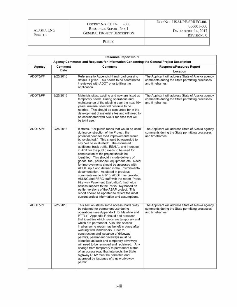
ALASKA LNG PROJECT
DOCKET NO. CP17-___-000 RESOURCE REPORT NO. 1
GENERAL PROJECT DESCRIPTION
DOC NO: USAI-PE-SRREG-00-000001-000
DATE: APRIL 14, 2017 REVISION: 0
PUBLIC
1-lii
Resource Report No. 1 Agency Comments and Requests for Information Concerning the General Project Description
Agency Comment Date
Comment Response/Resource Report Location
ADOT&PF 9/25/2016 Reference to Appendix H and road crossing details is given. This needs to be coordinated / reviewed with ADOT prior to filing the application.
The Applicant will address State of Alaska agency comments during the State permitting processes and timeframes.
ADOT&PF 9/25/2016 Materials sites, existing and new are listed as temporary needs. During operations and maintenance of the pipeline over the next 40+ years, material sites will continue to be needed. This should be accounted for in the development of material sites and will need to be coordinated with ADOT for sites that will be joint use.
The Applicant will address State of Alaska agency comments during the State permitting processes and timeframes.
ADOT&PF 9/25/2016 It states, “For public roads that would be used during construction of the Project, the potential need for road improvements would be evaluated.” This should be reworded to say “will be evaluated”. The estimated additional truck traffic, ESAL’s, and increase in ADT for the public roads to be used for construction of the project should be identified. This should include delivery of goods, fuel, personnel, equipment, etc. Need for improvements should be assessed with ADOT input and defined in the Environmental documentation. As stated in previous comments made 4/3/15, ADOT has provided AKLNG and FERC staff with the report ‘Parks Highway Pavement Evaluation’, that helps assess impacts to the Parks Hwy based on earlier versions of the ASAP project. This report should be updated to reflect the most current project information and assumptions.
The Applicant will address State of Alaska agency comments during the State permitting processes and timeframes.
ADOT&PF 9/25/2016 This section states some access roads “may be retained for permanent use during operations (see Appendix F for Mainline and PTTL).” Appendix F should add a column that identifies which roads are temporary and which are permanent. Also, this section implies some roads may be left in place after working with landowners. Prior to construction and issuance of driveway permits, permanent driveways must be identified as such and temporary driveways will need to be removed and reclaimed. Any change from temporary to permanent status of an access road that intersects the State highway ROW must be permitted and approved by issuance of a new driveway permit.
The Applicant will address State of Alaska agency comments during the State permitting processes and timeframes.

ALASKA LNG PROJECT
DOCKET NO. CP17-___-000 RESOURCE REPORT NO. 1
GENERAL PROJECT DESCRIPTION
DOC NO: USAI-PE-SRREG-00-000001-000
DATE: APRIL 14, 2017 REVISION: 0
PUBLIC
1-liii
Resource Report No. 1 Agency Comments and Requests for Information Concerning the General Project Description
Agency Comment Date
Comment Response/Resource Report Location
ADOT&PF 9/25/2016 Table 1.3.6-1 This section lists several airstrips that may be used for the Project. The table says 18 of the airports listed either require upgrades or it is yet to be determined if upgrades are needed. Many of these airports are State maintained and controlled. Once it is determined which airports will be used, Project staff should meet with ADOT staff to discuss necessary improvements and to what standard. This table and information should be consistent with the information provided on page 1-118 and 1-119, which lists airports to be used for personnel distribution.
The Applicant will address State of Alaska agency comments during the State permitting processes and timeframes.
ADOT&PF 9/25/2016 This sections states, “A preliminary list of potential sources for these various materials is included in Resource Report No. 6, Section 6.3.1”. No list is found under this section but is found in Appendix F of Resource Report No. 6.
The Applicant will address State of Alaska agency comments during the State permitting processes and timeframes.
ADOT&PF 9/25/2016 The last paragraph on this page states, “The totality of these circumstances warrant FERC’s inclusion of the Kenai Spur Highway relocation project in its environmental analysis as a connected action.” What does this mean with respect to the timeframe in which actual construction can be done? Must the analysis be complete prior to construction? Must FERC issue the Notice to Proceed to Construct before the KSH can be relocated? This needs to be spelled out and if so, factored into the Project Construction Schedule.
The Applicant will address State of Alaska agency comments during the State permitting processes and timeframes.
ADOT&PF 9/25/2016 Figure 1.3.9-3 is confusing at best. The ‘Recommended Alternatives’ listed on the bottom left of the figure are not intuitive and need to be better defined / related to the heavy lines shown on the map. An appendix dedicated to the Kenai Spur Relocation, whether in this report or another, seems appropriate.
The Applicant will address State of Alaska agency comments during the State permitting processes and timeframes.
ADOT&PF 9/25/2016 Reference to Table 1.3.2-8 is incorrect. The Applicant will address State of Alaska agency comments during the State permitting processes and timeframes.
ADOT&PF 9/25/2016 Reference to Table 1.3.2-9 is incorrect. The Applicant will address State of Alaska agency comments during the State permitting processes and timeframes.

ALASKA LNG PROJECT
DOCKET NO. CP17-___-000 RESOURCE REPORT NO. 1
GENERAL PROJECT DESCRIPTION
DOC NO: USAI-PE-SRREG-00-000001-000
DATE: APRIL 14, 2017 REVISION: 0
PUBLIC
1-liv
Resource Report No. 1 Agency Comments and Requests for Information Concerning the General Project Description
Agency Comment Date
Comment Response/Resource Report Location
ADOT&PF 9/25/2016 The timeline to complete the relocation of the Kenai Spur Highway is very ambitious. If the LNG Plant is to begin 4Q of 2019 that only leaves approximately 3 years from the time these reports are finalized to have KSH relocated. Same comments as listed above for section 1.3.9.1 pg. 1-84, apply here.
The Applicant will address State of Alaska agency comments during the State permitting processes and timeframes.
ADOT&PF 9/25/2016 Same comments as above. The Applicant will address State of Alaska agency comments during the State permitting processes and timeframes.
ADOT&PF 9/25/2016 Table 1.5.2-1 estimated additional truck traffic, ESAL’s, and increase in ADT for public roads to be used for construction of the project should be identified. This should include delivery of goods, fuel, personnel, equipment, etc. Need for improvements should be assessed with ADOT input and defined in the Environmental documentation. As stated in previous comments made 4/3/15, ADOT has provided AKLNG and FERC staff with the report ‘Parks Highway Pavement Evaluation’, that helps assess impacts to the Parks Hwy based on earlier versions of the ASAP project. This report should be updated to reflect the most current project information and assumptions. It should also be expanded to include other routes as listed in table 1.5.2-1.
The Applicant will address State of Alaska agency comments during the State permitting processes and timeframes.
ADOT&PF 9/25/2016 See comments for section 1.3.6 Project Airstrips.
The Applicant will address State of Alaska agency comments during the State permitting processes and timeframes.
ADOT&PF 9/25/2016 Referring to Talkeetna Airport – Looking at survey information used for the last ALP, it appears that the runway could be extended 500’ on the north end without a significant problem. (Extending the runway to the south could have both wetland and floodplain impacts.). However, there was no mention of the aircraft type associated with the need for 500 more feet of runway. The current runway is B-II which means it has a 75-foot width and runway safety area dimensions and a runway to parallel taxiway offset sized accordingly. Larger aircraft are not precluded from operation on a B-II runway, but if a wider runway were required (C-II or B-III etc.), there would likely be wetland and floodplain impacts to increasing all the associated geometry. It should also be mentioned that although the current airport surfaces are paved, some of the taxiways and aprons
The Applicant will address State of Alaska agency comments during the State permitting processes and timeframes.

ALASKA LNG PROJECT
DOCKET NO. CP17-___-000 RESOURCE REPORT NO. 1
GENERAL PROJECT DESCRIPTION
DOC NO: USAI-PE-SRREG-00-000001-000
DATE: APRIL 14, 2017 REVISION: 0
PUBLIC
1-lv
Resource Report No. 1 Agency Comments and Requests for Information Concerning the General Project Description
Agency Comment Date
Comment Response/Resource Report Location
being constructed with the current project will not be paved. Helicopters regularly use Talkeetna Airport. The FAA does not require dedicated facilities for them. Whether the airport could absorb the additional absorb the additional helicopter traffic without additional facilities needs to be determined, and if so, addressed in the EIS. ADOT&PF requests additional information on the following: clarification of aircraft type that are anticipated to use the airport and whether a B-II runway is adequate; preliminary cost estimates along with probable funding source for any extension; and projected schedule for any improvements as they relate to the larger pipeline construction effort
ADOT&PF 9/25/2016 The estimated truck loads for material, pipe, equipment, etc. should be summarized by route. The impacts of the additional traffic on the highways and on safety should be defined. Much of this information is scattered throughout the report and referenced to other reports. It would be nice to have a consolidated assessment of impact to highway infrastructure in one appendices or location of primary report.
The Applicant will address State of Alaska agency comments during the State permitting processes and timeframes.
ADOT&PF 9/25/2016 The 57,000 truckloads of other materials seems low. What is the number of trucks for imported backfill material?
The Applicant will address State of Alaska agency comments during the State permitting processes and timeframes.
ADOT&PF 9/25/2016 The first bulleted work item is to “Work with ADOT&PF to permanently redirect third-party traffic from the Kenai Spur Highway segment to be abandoned;”. See comments above regarding timelines for the KSH relocation.
The Applicant will address State of Alaska agency comments during the State permitting processes and timeframes.
ADOT&PF 9/25/2016 It states, “For public roads that would be used during construction of the Project, the potential need for road improvements would be evaluated.” See previous comments for section 1.3.4, pg. 1- 71.
The Applicant will address State of Alaska agency comments during the State permitting processes and timeframes.
ADOT&PF 9/25/2016 Reference to Section 1.3.2.1.4.3 is incorrect. The Applicant will address State of Alaska agency comments during the State permitting processes and timeframes.
ADOT&PF 9/25/2016 Encroachment Permit – the reason listed for why the permit is required should state something along the lines of “for non-highway uses within the ROW”
The Applicant will address State of Alaska agency comments during the State permitting processes and timeframes.

ALASKA LNG PROJECT
DOCKET NO. CP17-___-000 RESOURCE REPORT NO. 1
GENERAL PROJECT DESCRIPTION
DOC NO: USAI-PE-SRREG-00-000001-000
DATE: APRIL 14, 2017 REVISION: 0
PUBLIC
1-lvi
Resource Report No. 1 Agency Comments and Requests for Information Concerning the General Project Description
Agency Comment Date
Comment Response/Resource Report Location
ADOT&PF 9/25/2016 Utility Permit – the reason listed for why the permit is required should include facilities longitudinal and within the ROW.
The Applicant will address State of Alaska agency comments during the State permitting processes and timeframes.
ADOT&PF 9/25/2016 The typical section should be modified to show a minimum of 48” from bottom of ditch line to the top of the proposed gas pipeline. This minimum depth extends to 10’ beyond the outer top edge of the ditch section. See attached typical from ADOT Utility Manual.
The Applicant will address State of Alaska agency comments during the State permitting processes and timeframes.
ADOT&PF 9/25/2016 This table should add a column to indicate if the road and approach to an ADOT highway is permanent or temporary. See previous comments for page 1-72, Section 1.3.4.2.
The Applicant will address State of Alaska agency comments during the State permitting processes and timeframes.
ADOT&PF 9/25/2016 The following comments were submitted on 8/11/2015 to FERC and it is unclear as to whether these comments were addressed or considered. Franklin Bluffs Camp/PSY - As noted in previous comments, ADOT has had a request to DNR for this parcel since the 80’s. ADOT intends to construct a permanent maintenance facility at Franklin Bluffs. A maintenance station at this location provides the optimum distance between existing stations, facilities grading, snow plowing and other maintenance operations. This location is used to store materials such as calcium and access is needed. If the project constructs a permanent facility it could be relinquished to ADOT upon completion of construction. Happy Valley Camp/PSY - As indicated on their mapping that area designated for their camp is where we stock pile material extracted from the Sag. Losing this site would add 20 miles of haul from the next closest pit either side and is also a storage site for our calcium also. There would need to be some coordination for their use of this material site. The lay down yard is in a good place; maybe that area would work for a camp also. Atigun PSY - This area is shown as a pipe laydown yard. While the hatched area isn’t an issue, we need to be able to maintain access to our interest which is an old garage shown on the mapping. Chandalar PSY - Hatched area shown is adjacent to the camp, would ask that they ensure that we maintain our access. Gold Creek PSY - The hatched area for the pipe lay down pad is the only area that we are permitted to mine. The line next to Gold Creek has a cabin, shouldn’t be an issue unless they try to mine that area. Old Man Camp/PSY - This area originally built with the material from MP 105 pit which
The Applicant will address State of Alaska agency comments during the State permitting processes and timeframes.

ALASKA LNG PROJECT
DOCKET NO. CP17-___-000 RESOURCE REPORT NO. 1
GENERAL PROJECT DESCRIPTION
DOC NO: USAI-PE-SRREG-00-000001-000
DATE: APRIL 14, 2017 REVISION: 0
PUBLIC
1-lvii
Resource Report No. 1 Agency Comments and Requests for Information Concerning the General Project Description
Agency Comment Date
Comment Response/Resource Report Location
has naturally occurring asbestos. The pad has since been encapsulated and would not recommend any kind of disturbance of the ground. South Branch West Fork Dall River PSY - This material site is active and would need to ensure access. Tributary to North Fork Ray River PSY - Need to ensure access to the Material site is maintained. Five Mile Camp/PSY – Consider using the old airport site for a camp/storage yard. Erickson Creek PSY - Need to ensure access to the pit. This is also a shared material site that Alyeska uses. Cantwell Camp/PSY - The Cantwell Road is a substandard road and is not suitable for heavy and repetitive haul truck traffic. Additionally, ½ mile of the road is along a residential area with a fair amount of foot and ORV traffic.
ADOT&PF 9/25/2016 Appendix L doesn’t accurately report/ list all ADOT projects within the “reasonably foreseeable future” for projects within the AOI. Both the State Transportation Improvement Plan (STIP) and the Airport Improvement Plan (AIP) are documents available to the public and are thoroughly vetted via a public process. These documents identify ADOT’s plan for future infrastructure improvements to the State’s highways and airports. These Plans are updated and amended on a routine basis. Table 2 appears to make a limited attempt at listing 3 ADOT projects on the Dalton, Sterling and Seward Highways, but is by no means a complete list of proposed future improvements along those routes. It is unclear as to whether the Table 3 is intended to be list of proposed improvements needed to facilitate construction of the Project. If so, it should be labeled as such. Also, estimated cost of these improvements should be listed along with the entity that is expected to build the improvements. Better location identification is needed as Figures 3 & 4 are of little use.
The Applicant will address State of Alaska agency comments during the State permitting processes and timeframes.
SOA / ADF&G
An ADF&G T16 Fish Habitat Permit also would be required for gravel removal activities within a resident fish stream. Similarly, a permit also would be required for culvert or bridge installations across anadromous fish streams.
The Applicant will address State of Alaska agency comments during the State permitting processes and timeframes.

ALASKA LNG PROJECT
DOCKET NO. CP17-___-000 RESOURCE REPORT NO. 1
GENERAL PROJECT DESCRIPTION
DOC NO: USAI-PE-SRREG-00-000001-000
DATE: APRIL 14, 2017 REVISION: 0
PUBLIC
1-lviii
Resource Report No. 1 Agency Comments and Requests for Information Concerning the General Project Description
Agency Comment Date
Comment Response/Resource Report Location
SOA / ADHSS
Additional information on construction camps is needed, particularly: closed vs. open camps, transportation to camps inaccessible by bus, how workers will get to camps, a reference to a camp management plan, etc. (or include a reference to another RR if that information is provided elsewhere)
The Applicant will address State of Alaska agency comments during the State permitting processes and timeframes.
SOA / ADHSS
Add a general sentence about the source of water for dust suppression efforts
The Applicant will address State of Alaska agency comments during the State permitting processes and timeframes.
USACE 9/26/2016 11 a. Need location for each access road, helipad, construction camp, pipe storage area, material extraction site and material disposal sites.
Water sources are outlined in the Water Use Plan found as Appendix K of Resource Report No. 2.
USACE 9/26/2016 11b. Typical drawings indicate gas and water pipelines would be on separate vertical support members (VSMs). Please describe whether it’s practicable to collocate these utilities on one set of VSMs.
The water line and the gas lines are on opposite sides of the Gas Treatment Plant. It is not possible to co-locate the lines on the same VSM’s. Reference: Resource Report No.13A, Appendix A.1 GTP Site Plan, Drawing USAG-EC-LDLAY-00-001004-000.
USACE 9/26/2016 11c. Drawings should follow the guidance of SPN-2010-45. Specifically map scale is generally one inch to 100 or 200 feet for best readability, maximum one inch to 400 feet. A number of maps are not readable due to scale and are not considered sufficient for permitting purposes.
Permit quality drawings will be prepared when the draft permit application is prepared and filed with the FERC application. Scale will stay as is for FERC application materials.
USACE 9/26/2016 11d. Trench drawings (Figures E-27 and E-28) need to show the dimension for the full extent of the fill footprint.
The Figures in Appendix E of Resource Report No. 1 have been updated.
USACE 9/26/2016 11e.How does AKLNG plan to account for shoofly roads (E-66) in wetlands? If not identified prior to permit issuance, these features would require a modification to the permit.
All the shoofly roads have been identified in the Project Footprint found in Resource Report No. 1, Appendix A: Aerial Imagery and USAG Mapping of Preliminary Facility Locations.
USACE 9/26/2016 11f. Dimensions needed for wetland impacts associated with off ramps from existing access roads.
Access road impacts to wetlands are provided in Appendix E of Resource Report No. 2.
USACE 9/26/2016 11g. Provide rationale for determining when or if helicopter pads (E-67 and E-68) are needed? Is it possible to have these collocated in camps or other uplands/disturbed areas and avoid wetland impacts?
Helicopter use during construction would use camps and other sites already cleared for construction workspace. Helicopter pads associated with MLBV sites are for operations and would be required at the MLBV sites.

ALASKA LNG PROJECT
DOCKET NO. CP17-___-000 RESOURCE REPORT NO. 1
GENERAL PROJECT DESCRIPTION
DOC NO: USAI-PE-SRREG-00-000001-000
DATE: APRIL 14, 2017 REVISION: 0
PUBLIC
1-lix
Resource Report No. 1 Agency Comments and Requests for Information Concerning the General Project Description
Agency Comment Date
Comment Response/Resource Report Location
USACE 9/26/2016 11h. Equipment crossing drawings need typical dimensions.
The Applicant will address this comment prior to the initiation of the EIS process.
USACE 9/26/2016 11i. Is clearing for Heliport approach/departure modes-clearing area about vegetative roots? Any mechanized land clearing in wetlands may be subject to review and approval under the Corps jurisdiction prior to commencement of activities.
The comment is noted. The clearing is related to above-ground plant growth that could hit or damage helicopter rotors. Project will identify these locations and footprint prior to permitting.
USACE 9/26/2016 11j. Elevation drawings, with dimensions, for camps are needed. Can the camp modules be stacked to minimize impacts? Please include a summary of avoidance and minimization strategies used onsite to maximize uplands or existing disturbed areas and avoid and reduce wetland impacts.
The camp modules are designed to be single story. To the extent possible, camp locations have been selected on previously disturbed sites (existing pads). New camp pad locations were selected as upland sites where practicable. Elevations of the camp pads have been provided in Appendix E of Resource Report No. 1.
USACE 9/26/2016 11k. Elevation drawings, with dimensions, are needed for Pipe Storage Yards. Please include a summary of avoidance and minimization strategies used onsite to maximize uplands or existing disturbed areas and avoid and reduce wetland impacts.
Most locations for pipe or contractor yards and construction camps are on previously disturbed locations (see Table 1.3.2-10). Final drawings of the layout and use of each site would be completed for permitting with the appropriate land managing agency.
USACE 9/26/2016 11L. Elevation drawings, with dimension, are needed for Standalone Contractor yards and Construction water discharge sites. Please include a summary of avoidance and minimization strategies used onsite to maximize uplands or existing disturbed areas and avoid and reduce wetland impacts.
To the extent possible, standalone contractor yards have been selected on previously disturbed sites (existing pads). New standalone contractor yard locations were selected as upland sites where practicable. Elevations of the contractor yards have been provided in Appendix E of Resource Report No. 1.
USACE 9/26/2016 11m. For any temporary-use storage yards and camps, Resource Report No. 1 indicates that the material will be removed to grade and allowed to revegetate. How will the material be recovered and how/where will it be disposed?
There are no plans to remove any fill material that is placed.
USACE 9/26/2016 11n. Elevation drawings needed for Construction hydrostatic test point areas and conceptual “zee” fault crossing design strike-slip fault support sleepers (the symbol looks like you are saying they are on concrete, is this correct?).
The fault crossing and hydrostatic test point drawings have been updated in Appendix E.
USACE 9/26/2016 11o. Is AKLNG including all previously disturbed sites as existing fill/uplands? In some cases, previously disturbed areas may
Mapping of disturbed areas is typically shown as uplands in wetland mapping. Wetland mapping was completed without pre-disposition of prior landscape use. Previously disturbed sites are

ALASKA LNG PROJECT
DOCKET NO. CP17-___-000 RESOURCE REPORT NO. 1
GENERAL PROJECT DESCRIPTION
DOC NO: USAI-PE-SRREG-00-000001-000
DATE: APRIL 14, 2017 REVISION: 0
PUBLIC
1-lx
Resource Report No. 1 Agency Comments and Requests for Information Concerning the General Project Description
Agency Comment Date
Comment Response/Resource Report Location
have converted back to jurisdictional wetlands.
characterized separately from uplands, but do not meet the criteria for jurisdictional wetlands. Unvegetated previously disturbed sites are characterized as “Disturbed” as discussed in Resource Report No. 2, Section 2.4.1.1 and in the Wetland Report provided as Appendix G to Resource Report No. 2
USACE 9/26/2016 11p. Identify gas interconnection point locations and include a schematic of each (narrative indicates there will be different sizes; each ‘size’ will need its own typical drawing).
The Applicant will address this comment prior to the issuance of the DEIS.
USACE 9/26/2016 11q. Please identify all DOT transportation infrastructure which may be utilized to support the project, to include airports, and provide a description of any modifications which may be required.
The information is contained in the FERC application in Resource Report No. 5, Section 5.3.5.
USACE 9/26/2016 11r. Access roads on Resource Report No. 1 Appendix A appear to lack apparent use or connection to material sites or other pipeline support infrastructure (i.e., one area has two access roads in less than a quarter mile stretch (AR-GA-N-205.1 and AR-GA- PSY-N-205.3, also AR-GA-N-220.3 and AR-GA-N-220.4), and another area has seven access roads within a six mile distance (AR-XG-N-210.7 – AR-N- 215.8), this seems excessive). One access road is labelled MS-E-230.9, but has no material site associated with it. All access roads, whether existing or proposed, need to be shown that will support the project, including those accessing material sites, camps, PSY sites, etc.
Appendixes A & F of Resource Report No. 1 have been updated. Appendix F of Resource Report No. 1 identifies which roads are “New” or “Existing”. The use of Public Roads has been assumed. However, public roads are not included in Appendix A or F.
USACE 9/26/2016 11s. What are the modifications/new facilities proposed at the PBU? Please include plan view and cross-section drawings with appropriate dimensions.
Section 1.3.9 has been updated with all the information that Alaska LNG can gather from the third parties proposing the non-jurisdictional facilities.
USACE 9/26/2016 11t. What are the modifications/new facilities proposed at the PTU? Please include plan view and cross-section drawings with appropriate dimensions.
Section 1.3.9 has been updated with all the information that Alaska LNG can gather from the third parties proposing the non-jurisdictional facilities.
USACE 9/26/2016 11u. Regarding the proposed relocation of the Kenai Spur Highway, provide plan view and cross section drawings of the proposed realignment. Additionally, please include a descriptive narrative for the project, a rationale for the single and complete nature of the project (independent utility) and the
Section 1.3.9 has been updated with all the information that Alaska LNG can gather from the third parties proposing the non-jurisdictional facilities.
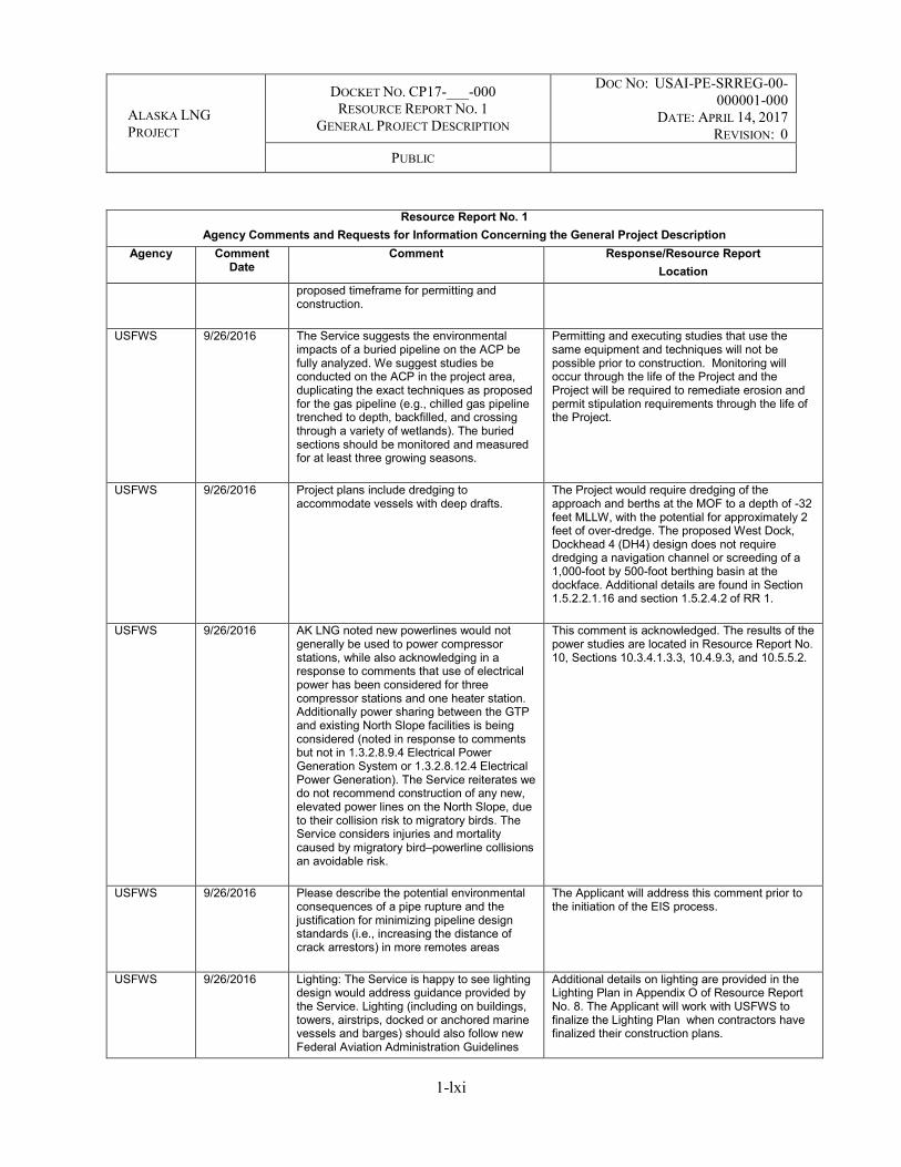
ALASKA LNG PROJECT
DOCKET NO. CP17-___-000 RESOURCE REPORT NO. 1
GENERAL PROJECT DESCRIPTION
DOC NO: USAI-PE-SRREG-00-000001-000
DATE: APRIL 14, 2017 REVISION: 0
PUBLIC
1-lxi
Resource Report No. 1 Agency Comments and Requests for Information Concerning the General Project Description
Agency Comment Date
Comment Response/Resource Report Location
proposed timeframe for permitting and construction.
USFWS 9/26/2016 The Service suggests the environmental impacts of a buried pipeline on the ACP be fully analyzed. We suggest studies be conducted on the ACP in the project area, duplicating the exact techniques as proposed for the gas pipeline (e.g., chilled gas pipeline trenched to depth, backfilled, and crossing through a variety of wetlands). The buried sections should be monitored and measured for at least three growing seasons.
Permitting and executing studies that use the same equipment and techniques will not be possible prior to construction. Monitoring will occur through the life of the Project and the Project will be required to remediate erosion and permit stipulation requirements through the life of the Project.
USFWS 9/26/2016 Project plans include dredging to accommodate vessels with deep drafts.
The Project would require dredging of the approach and berths at the MOF to a depth of -32 feet MLLW, with the potential for approximately 2 feet of over-dredge. The proposed West Dock, Dockhead 4 (DH4) design does not require dredging a navigation channel or screeding of a 1,000-foot by 500-foot berthing basin at the dockface. Additional details are found in Section 1.5.2.2.1.16 and section 1.5.2.4.2 of RR 1.
USFWS 9/26/2016 AK LNG noted new powerlines would not generally be used to power compressor stations, while also acknowledging in a response to comments that use of electrical power has been considered for three compressor stations and one heater station. Additionally power sharing between the GTP and existing North Slope facilities is being considered (noted in response to comments but not in 1.3.2.8.9.4 Electrical Power Generation System or 1.3.2.8.12.4 Electrical Power Generation). The Service reiterates we do not recommend construction of any new, elevated power lines on the North Slope, due to their collision risk to migratory birds. The Service considers injuries and mortality caused by migratory bird‒powerline collisions an avoidable risk.
This comment is acknowledged. The results of the power studies are located in Resource Report No. 10, Sections 10.3.4.1.3.3, 10.4.9.3, and 10.5.5.2.
USFWS 9/26/2016 Please describe the potential environmental consequences of a pipe rupture and the justification for minimizing pipeline design standards (i.e., increasing the distance of crack arrestors) in more remotes areas
The Applicant will address this comment prior to the initiation of the EIS process.
USFWS 9/26/2016 Lighting: The Service is happy to see lighting design would address guidance provided by the Service. Lighting (including on buildings, towers, airstrips, docked or anchored marine vessels and barges) should also follow new Federal Aviation Administration Guidelines
Additional details on lighting are provided in the Lighting Plan in Appendix O of Resource Report No. 8. The Applicant will work with USFWS to finalize the Lighting Plan when contractors have finalized their construction plans.

ALASKA LNG PROJECT
DOCKET NO. CP17-___-000 RESOURCE REPORT NO. 1
GENERAL PROJECT DESCRIPTION
DOC NO: USAI-PE-SRREG-00-000001-000
DATE: APRIL 14, 2017 REVISION: 0
PUBLIC
1-lxii
Resource Report No. 1 Agency Comments and Requests for Information Concerning the General Project Description
Agency Comment Date
Comment Response/Resource Report Location
(12/04/15). These guidelines were amended to reduce bird mortalities with towers and other markers, while providing for safe air space. They are available at: http://www.faa.gov/documentLibrary/media/Advisory_Circular/AC_70_7460-1L_.pdf The Service will work with the applicant to ensure that the latest, component-specific guidance (e.g. guidance specific to communication towers, buildings) is incorporated in project design, to minimize potential for avian collisions. In general, on the Arctic Coastal Plain (ACP), we ask that outdoor security or safety lights be motion-triggered, downcast, and/or down-shielded, and directed inward whenever possible to prevent “star” effects when viewed offsite. This recommendation applies to both permanent and temporary lighting used during construction and operation. We also ask that lights inside buildings be motion-triggered, and blackout shades be installed and used on outward- facing windows at dark, when migratory birds are present (May through October on the ACP).
USFWS 9/26/2016 We suggest elevating the PTTL pipeline on VSMs over the river crossings which is standard construction on the North Slope. This will prevent thermokarst and erosion of river banks as is likely to happen with a trenched pipeline.
Please see Appendix E of Resource Report No. 10 for the analysis of design methods considered along the PTTL.
USFWS 9/26/2016 The proposed Operations Center pad and the north end of the proposed Gas Treatment pad (flares) border a wetland complex/lake that is heavily used by breeding/brood-rearing and staging waterfowl and shorebirds. We suggest alternative locations for these pads – for example the OCP could be moved north and to the west side of the proposed road. The flares proposed for the GTP pad should be relocated away from the lake to avoid impacts to birds.
GTP layout alternatives are discussed in Section 10.5.4 of Resource Report No. 10, including constraints related to placement of the flares and Operations Center. When siting the entire facility, efforts were taken to minimize impacts to waterbodies. Also see Section 1.3.2.8.9.6 of Resource Report No. 1, the flares would not be in continuous use, only for startup, emergency, pre-commissioning, commissioning, shutdown, or upset conditions.
USFWS 9/26/2016 GTP communications tower should be placed as far away from the wetland complex east and south of the pad to minimize bird strikes. Moving the OC pad to the west side of the road and to the north may help. The Service is willing to work with the applicant to minimize tower impacts to migratory birds through the design and lighting of the tower.
Comment acknowledged.

ALASKA LNG PROJECT
DOCKET NO. CP17-___-000 RESOURCE REPORT NO. 1
GENERAL PROJECT DESCRIPTION
DOC NO: USAI-PE-SRREG-00-000001-000
DATE: APRIL 14, 2017 REVISION: 0
PUBLIC
1-lxiii
Resource Report No. 1 Agency Comments and Requests for Information Concerning the General Project Description
Agency Comment Date
Comment Response/Resource Report Location
USFWS 9/26/2016 Water Reservoir – the Putuligayuk River is known to run saline during the winter as well as during storm surges from the north. This may increase in frequency and duration with climate change. Also, fish screens should be installed at use inlets to present mortality. We suggest other sources of water be investigated for this project such as the Sagavanirktok River. The Sag is currently being used as a water source for this area of the oil fields and for Deadhorse. An expansion of the Sag Reservoir was being considered several years ago to increase the supply – but has not yet been built.
Alternative sources of water are addressed in Resource Report No. 10, Section 10.5.4.3.
USFWS 9/26/2016 Pipeline Material Sites – The document states most of the granular material needed for the project will be used for pipeline construction. If the pipeline is elevated on VSMs on the Arctic Coastal Plain (ACP) this would substantially reduce the need for gravel resources in this area.
Most of the gravel in the Arctic Coastal Plain is for the GTP and other non-jurisdictional facilities.
USFWS 9/26/2016 Mine Site – We suggest existing sources of gravel also be considered in order to minimize the size of the proposed mine site. Mine sites should be developed consistent with Best Management Practices developed by the AK DNR for the North Slope to prevent thermokarst and potential draining of adjacent wetlands.
Alternative sources of gravel are addressed in Resource Report No. 10, Section 10.5.4.3. The mine site would be developed following best management practices for working on the North Slope as well as FERC Order and permit conditions.
USFWS 9/26/2016 Construction and Logistics: The Service has concerns the oceangoing barge bridge installed to allow module roll-off could impede passage of wildlife (specifically molting brant, long-tailed duck, and other waterfowl) which often transit back and forth in the nearshore environment in this location during mid to late summer. Please discuss the specific timing and duration of barge bridge installation/the four planned sealifts with the Service to ensure maximum impact avoidance for these migratory birds and other wildlife.
The Applicant will address this comment prior to the issuance of the DEIS.
USFWS 9/26/2016 72,000 acres will be temporarily impacted but after construction is completed, 13,000 acres would be used for project operation. Are the 13,000 acres considered temporarily impacted? Or is this another 13,000 in addition to the 72,000? Define temporary impacts.
This is a subset of the 72,000 construction acres that will be impacted. The 8,600 acres represents permanent impact and the remainder of the 72,000 acres will be restored.
USFWS 9/26/2016 Telecommunications Tower: The Service is happy to see telecommunications tower
Comment acknowledged.

ALASKA LNG PROJECT
DOCKET NO. CP17-___-000 RESOURCE REPORT NO. 1
GENERAL PROJECT DESCRIPTION
DOC NO: USAI-PE-SRREG-00-000001-000
DATE: APRIL 14, 2017 REVISION: 0
PUBLIC
1-lxiv
Resource Report No. 1 Agency Comments and Requests for Information Concerning the General Project Description
Agency Comment Date
Comment Response/Resource Report Location
lighting for the GTP would be designed to address guidance provided by the Service, to reduce the potential for avian collisions. Additionally, we recommend the tower structure be designed to minimize potential impacts, following the Service Interim Guidelines for Recommendations on Communications Tower Siting, Construction, Operation, and Decommissioning. We are providing these guidelines in an email attachment. For example, we recommend self-supporting, un-guyed towers be used wherever possible. This comment applies to all project-associated towers. On the ACP, Service encourages use of monopole rather than lattice towers, to discourage perching and nesting by ravens and raptors/birds of prey, unless use of a monopole structure would require addition of guy wires on an otherwise un-guyed tower. In these cases, projects should work with the Service to incorporate anti-perching, anti-nesting devices into project design. This comment applies to all towers being constructed on the ACP.
USFWS 9/26/2016 Project Construction Procedures: We recommend the following Best Management Practices, to help avoid and minimize risk to threatened eiders and other migratory bird species: Ground-disturbing work (e.g. clearing, mowing, placement of fill) will take place outside the bird nesting season to avoid direct and indirect impacts to breeding birds. The Project will follow the most current guidance available from the USFWS prior to the start of construction; If work must take place within the avoidance period, the project footprint should be rendered unsuitable for breeding birds prior to their arrival. For example, for ground nesting birds, this can be accomplished by placing geotextile fabric and at least one lift of gravel over the project footprint, prior to the onset of nesting. This would facilitate work during breeding season, minimizing impacts to eggs and young; AK LNG will contact the USFWS for specific recommendations if raptors or cliff-nesting birds may be nesting within the Project footprint; and USFWS recommended avoidance periods are currently being revised in Alaska.
Comment acknowledged. The Project will follow the most recent guidance from the U.S. Fish and Wildlife Service (USFWS) Region 7 regarding the recommended time periods to avoid vegetation clearing. In general, clearing of the construction right-of-way (ROW) will occur in the winter prior to a particular construction season. The Applicant will work with the USFWS on other means to avoid impacts or remove habitat prior to the nesting season.
USFWS 9/26/2016 The Service does not recommend trenching/buying the pipe on the North Slope unless it is in naturally –occurring thaw-stable
Construction Scheduling is discussed in Section 1.5 of Resource Report No. 1. Refer to Table

ALASKA LNG PROJECT
DOCKET NO. CP17-___-000 RESOURCE REPORT NO. 1
GENERAL PROJECT DESCRIPTION
DOC NO: USAI-PE-SRREG-00-000001-000
DATE: APRIL 14, 2017 REVISION: 0
PUBLIC
1-lxv
Resource Report No. 1 Agency Comments and Requests for Information Concerning the General Project Description
Agency Comment Date
Comment Response/Resource Report Location
soils (gravel soils of the historic Sagavanirktok River channel). If this is the case, the Project should consider finishing Spread One as late as possible in the mainline construction to decrease the time the pipeline is being unused (un-chilled) in the trench on the North Slope. This might help to minimize impacts from permafrost thaw and thermokarsting.
1.5.2-4 for the current project construction schedule.
USFWS 9/26/2016 Onshore Pipeline Construction and Execution Procedures, Mainline, Clearing: The Service appreciates clearing activities prior to construction are planned to typically occur in the winter season, as this will reduce potential impacts to breeding migratory birds. However, because the ground would be only minimally disturbed until just before construction, clearing three years prior to construction is sufficient time for regrowth of understory plants (including shrubs). Ground- and shrub-nesting migratory birds may nest in areas of regrowth, thereby reducing the efficacy of this protective measure. We suggest clearing one to two winters in advanced of scheduled construction is more appropriate. Please note activities in addition to clearing may impact nesting migratory birds. These activities, including mowing, brush hogging, hydroaxing, placement of fill, and stockpiling activities should be accomplished outside of the migratory bird nesting season, as identified in the most current version of Service guidance. The RR s should be updated to reflect this.
Table 1.5.2-3 and Table 1.5.2-4 of Resource Report No. 1 have been updated to indicate the Start of ROW Construction. ROW Construction includes clearing.
USFWS 9/26/2016 Timber is not typically considered riprap, but instead is used in natural streambank stabilization techniques.
Comment acknowledged. The referenced text was modified to note that timber is not included under the definition of riprap.
USFWS 9/26/2016 Onshore Pipeline Construction and Execution Procedures, Mainline, Lighting: A new italicized subheader is needed in this section of the document to separate Lighting from Clearing. If nighttime lighting is needed during the spring or fall shoulder seasons, when migratory birds may be transiting the construction area, we suggest the following lighting protocol: Lights should be downcast and/or down-shielded, and directed inward whenever possible to prevent “star” effects when viewed offsite, so as not to attract migrating birds and create a collision hazard.
The comment is acknowledged. Due to revisions, the new Section number is: 1.5.2.3.4.1. A new subheading was added called Lighting to separate lighting from clearing.

ALASKA LNG PROJECT
DOCKET NO. CP17-___-000 RESOURCE REPORT NO. 1
GENERAL PROJECT DESCRIPTION
DOC NO: USAI-PE-SRREG-00-000001-000
DATE: APRIL 14, 2017 REVISION: 0
PUBLIC
1-lxvi
Resource Report No. 1 Agency Comments and Requests for Information Concerning the General Project Description
Agency Comment Date
Comment Response/Resource Report Location
USFWS 9/26/2016 Migratory Bird Treaty Act: The MBTA is an Act, not a permit that needs to be obtained. Therefore, the column header, “Permit or Plan,” is somewhat misleading, as is the column, “Why Permit is Required.” We suggest these columns be changed to be more inclusive. It is important to consider the MBTA in project planning and implementation, so as to be in compliance with the Act. We suggest adding the definition of “take” in the table. In addition, we suggest removing the website referenced in the “Data Needs” column, as websites are often subject to change and hyperlinks therefore expire. In place of the website note that general guidance for land clearing and ground disturbing activities to avoid impacts to nesting migratory birds is available through the USFWS Region 7.
Comment acknowledged. Column headers were edited to Permit, Plan or Act; and Why Permit or Compliance with Act is Required. The Definition column was updated to include the definition from 50 Code of Federal Regulations (CFR) 10.12 ("to pursue, hunt, shoot, wound, kill, trap, capture, or collect, or attempt to pursue, hunt, shoot, wound, kill, trap, capture, or collect.) The website reference was deleted and replaced with a note stating "General guidance for land clearing and ground disturbing activities to avoid impacts to nesting migratory birds will be obtained from the Region 7 of the USFWS." Once the application is provided to FERC, FERC will use and update information as appropriate for the drafting of the EIS.
USFWS 9/26/2016 Bald and Golden Eagle Take Permit: The Service suggests the applicant contact Region 7’s Migratory Bird Management Program to verify the 60-day estimate for permit approval. Also, note permit applications for eagle take are processed when the project has a defined footprint and specific sources of potential take can be identified, typically during permitting (after the EIS is published).
Comment acknowledged.
USFWS 9/26/2016 The Service recommends permanent bridges span the entire floodplain to allow for unobstructed floodplain function.
Comment Acknowledged. Text added to Resource Report No. 2 Section 2.3.8.2.1.4: Pilings and abutments will be located to minimize floodplain obstruction to the extent possible.
USFWS 9/26/2016 For sediment control, we recommend a minimum 50-foot vegetated buffer adjacent to wetlands and streams, and 100-foot minimum vegetated buffer on anadromous streams/river s and streams leading to anadromous waterbodies.
Project will utilize sediment barriers and other BMPs identified in Resource Report No. 2, Appendix N for erosion and sedimentation control on the construction ROW. Setbacks from Streams and Wetlands are identified in Resource Report No. 2 Section 2.6.
USCG 9/26/2016 The U.S. Coast Guard (USCG) Bridge Program offers the following comment regarding the Alaska Liquefied Natural Gas (LNG) Project Second Draft Resource Reports: RR 2 describes major, intermediate, and minor waterbodies; however, crossing methods were only described for the listed major waterbodies. Intermediate and minor waterways may also be subject to USCG jurisdiction for bridge permitting purposes. The following waterways along the proposed route have been determined to be navigable
Comment Acknowledged. USCG permit applications will be filed in the year prior to bridge use. The FERC EIS will address the NEPA requirements for crossing the rivers noted that require bridge permits.

ALASKA LNG PROJECT
DOCKET NO. CP17-___-000 RESOURCE REPORT NO. 1
GENERAL PROJECT DESCRIPTION
DOC NO: USAI-PE-SRREG-00-000001-000
DATE: APRIL 14, 2017 REVISION: 0
PUBLIC
1-lxvii
Resource Report No. 1 Agency Comments and Requests for Information Concerning the General Project Description
Agency Comment Date
Comment Response/Resource Report Location
by the USCG. Therefore, all temporary or permanent bridges, including aerial crossings of pipelines, fall under the jurisdiction of the USCG and may require Bridge Permits. Other activities taking place in these waterways may also require Coast Guard review and/or authorization. Please coordinate with the USCG 17th District Bridge Office to determine the minimum navigational clearance requirements and pier placement for any proposed bridges along the project's route. As part of its cooperating agency obligation under NEPA, the USCG will need to adopt the bridge-related portions of the environmental documents for this project. Impacts to environmental resources as a result of each proposed bridge and its pier placement should be included in these resource reports and NEPA documents to facilitate our cooperating agency responsibilities as part of the USCG bridge permitting process.
USCG 9/26/2016 Mainline Route, Putuligayuk River Sagavanirktok River, East Fork Kuparuk River Kuparuk River, Atigun River Dietrich River, Middle Fork Koyukuk River West Fork Koyukuk River South Fork Koyukuk River Jim River, Yukon River Hess Creek, West Fork, Tolovana River Tolovana River, Tatalina River Chatanika River Tanana River Nenana River, Middle Fork Chulitna River East Fork Chulitna River Chulitna River, Deshka River Yentna River Ivan River Lewis River Theodore River Beluga River
Comment Acknowledged. USCG permit applications will be filed in the year prior to bridge use. The FERC EIS will address the NEPA requirements for crossing the rivers noted that require bridge permits. This is addressed in Resource Report No. 2, Section 2.3.7.7
USCG 9/26/2016 Interdependent Project Facilities Pipeline PTTL, Shaviovik River Kadlerushilik River Sagavanirktok River Putuligayuk River
Comment Acknowledged. USCG permit applications will be filed in the year prior to bridge use. The FERC EIS will address the NEPA requirements for crossing the rivers noted that require bridge permits. This is addressed in Resource Report No. 2, Section 2.3.7.7.
PHMSA 12/14/2016 Table 1.3.2-11 – for mainline valve spacing – o PHMSA Comment: Does this table correctly show proposed location of mainline valves?
Table 1.3.2-11 correctly shows the mileposts for the mainline block valves based on filing the special permit for alternative spacing in Class 1 Locations.
EPA
9/30/2016
Integrating the AK LNG Project and the ASAP Project into a Comprehensive EIS. We understand that the State of Alaska (Alaska Gasline Development Corporation) may be assuming leadership of the AK LNG Project. If so, the Corporation would be the project proponent for both the AK LNG Project and
Comment acknowledged.

ALASKA LNG PROJECT
DOCKET NO. CP17-___-000 RESOURCE REPORT NO. 1
GENERAL PROJECT DESCRIPTION
DOC NO: USAI-PE-SRREG-00-000001-000
DATE: APRIL 14, 2017 REVISION: 0
PUBLIC
1-lxviii
Resource Report No. 1 Agency Comments and Requests for Information Concerning the General Project Description
Agency Comment Date
Comment Response/Resource Report Location
the smaller diameter in-state Alaska Stand Alone Pipeline Project. To maximize efficiency, we recommend that the planning and environmental review procedures for both the AK LNG Project and the ASAP Project be integrated into a single comprehensive EIS. We believe that such an approach would reduce delay, duplication and paperwork
EPA
9/30/2016
The Resource Reports evaluate the lifecycle of the project, including construction (7 years), operations, and maintenance (30 years). The Reports do not evaluate potential end of project life aspects such as abandonment, decommissioning, rehabilitation, or restoration. There are direct, indirect, and cumulative impacts associated with these types of activities. We recommend that the Reports evaluate the actions and impacts at the end of the 30-year life of the project. For certain facilities, activities and/or impacts that are considered temporary, such as the Material Offloading Facility (MOF) and access roads, we recommend that the Reports describe the removal and restoration of the site after the temporary facility/activity is no longer required. We recommend that the direct, indirect, and cumulative impacts associated with these temporary facilities/activities be evaluated and discussed in the Reports.
At the present time, it is not known what the requirements will be to address the facilities at the end of life of the project. Therefore, assessing those impacts is not possible.
FERC 10/26/2016 In the tables “Agency Comments and Requests for Information Concerning …” in each resource report, comment responses are provided that are not further carried into the text of the resource reports. Incorporate the information provided in the tables into the text of each resource report to allow readers to have a full understanding of the Project’s commitment and information. For example, in response to a comment from the U.S. Army Corps of Engineers (COE), Alaska Gasline Development Corporation; BP Alaska LNG, LLC; Conoco Phillips Alaska LNG Company; and ExxonMobil Alaska LNG, LLC (collectively referred to as Alaska LNG) commits to conducting additional sampling in both Cook Inlet and Prudhoe Bay in support of potential Alaska LNG Project (Project) dredging. A discussion of this commitment for sampling should be included in the text of the Application.
Comment Acknowledged. Details requested in the comments are reference and incorporated as applicable in the body of the resource reports

ALASKA LNG PROJECT
DOCKET NO. CP17-___-000 RESOURCE REPORT NO. 1
GENERAL PROJECT DESCRIPTION
DOC NO: USAI-PE-SRREG-00-000001-000
DATE: APRIL 14, 2017 REVISION: 0
PUBLIC
1-lxix
Resource Report No. 1 Agency Comments and Requests for Information Concerning the General Project Description
Agency Comment Date
Comment Response/Resource Report Location
FERC 10/26/2016 Address/respond to the comments provided by the Bureau of Land Management (BLM), U.S. Environmental Protection Agency (EPA), National Park Service (NPS), State of Alaska, COE, U.S. Coast Guard, U.S. Forest Service, and U.S. Fish and Wildlife Service. These comments are included as attachment A.
Comment acknowledged. Responses are provided.
FERC 10/26/2016 Include full citations for missing sources and referenced materials, including web- based data. Review all citations and confirm that there are corresponding literature references. Confirm that where multiple references are listed in a year that there are alphabetical modifiers that accurately align between the citation and references, and confirm that literature references are listed alphabetically and then chronologically to facilitate location of the accurate reference. Full citations were found to be missing for the references identified in attachment B; however, the list is not considered all-inclusive.
Comment acknowledged. The editorial changes have been made.
FERC 10/26/2016 Include cross references between resource reports for information applicable to multiple reports so it is clear where information can be found.
Comment acknowledged. The editorial changes have been made.
USFWS 9/26/2016 The Service suggests the environmental impacts of a buried pipeline on the ACP be fully analyzed. We suggest studies be conducted on the ACP in the project area, duplicating the exact techniques as proposed for the gas pipeline (e.g., chilled gas pipeline trenched to depth, backfilled, and crossing through a variety of wetlands). The buried sections should be monitored and measured for at least three growing seasons.
Field trials are not required to know that a buried pipeline can be successfully operated and maintained on the ACP. There are existing examples, including TAPS, which represents a more than worst-case scenario, as it is a hot oil pipeline, but which has operated successfully for decades. TAPS has a track record of demonstrating successful burial on the ACP with appropriate stabilization, revegetation, and water management. A buried, chilled pipeline in permafrost would not be problematic with appropriate control of erosion, revegetation, and adequate water management, including maintaining existing surface flow. The Alaska LNG field maintenance program and in-line inspection program would both apply a maintenance standard of "monitor, detect, and correct". A buried pipeline is safer to the general

ALASKA LNG PROJECT
DOCKET NO. CP17-___-000 RESOURCE REPORT NO. 1
GENERAL PROJECT DESCRIPTION
DOC NO: USAI-PE-SRREG-00-000001-000
DATE: APRIL 14, 2017 REVISION: 0
PUBLIC
1-lxx
Resource Report No. 1 Agency Comments and Requests for Information Concerning the General Project Description
Agency Comment Date
Comment Response/Resource Report Location
public, reduces security concerns and issues related to bullet strikes, and is more beneficial to caribou, which may be affected by multiple linear features, such as highways and elevated pipelines. In addition, the engineering reasons as to why the pipe cannot be elevated on the ACP, namely liquid dropout in the event of prolonged winter shutdown where reduced pressure would occur. A pipe exposed to the ambient air at cold temperatures and pressures below the phase change threshold would result in liquid drop out and infiltration of those liquids into pipeline facilities, which could cause damage and could create excessively long delays to remove and clean.
USFWS 9/26/2016 Project plans include dredging to accommodate vessels with deep drafts.
Comment acknowledged. The Project would require dredging of the approach and berths at the MOF to a depth of -32 feet MLLW, with the potential for approximately 2 feet of over-dredge. The proposed West Dock, Dockhead 4 (DH4) design does not require dredging a navigation channel. Additional details are found in Section 1.5.2.2.1.16 and section 1.5.2.4.2 of Resource Report No. 1.
ADOT&PF 9/25/2016 DOT is currently studying the need and feasibility of a second bridge crossing the Yukon River. This study is expected to be completed Fall 2017. Potential locations and direct or indirect impacts of a proposed second bridge, including collocating with gasline row, may need to be addressed in EIS.
The Applicant will address State of Alaska agency comments during the State permitting processes and timeframes.
ADOT&PF 9/25/2016 Given the magnitude of the project and the potential need for traffic mitigation measures, an overall traffic impact analysis should be completed with the EIS.
The Applicant will address State of Alaska agency comments during the State permitting processes and timeframes.
FERC 12/14/2016 Address/respond to the comments provided by the U.S. Department of Transportation (USDOT), Pipeline and Hazardous Materials Safety Administration (PHMSA) and the State of Alaska on draft Resource Reports Nos.11 and 13. These comments are included as attachment A.
The detailed comments from PHMSA are addressed in Resource Report No. 11.

ALASKA LNG PROJECT
DOCKET NO. CP17-___-000 RESOURCE REPORT NO. 1
GENERAL PROJECT DESCRIPTION
DOC NO: USAI-PE-SRREG-00-000001-000
DATE: APRIL 14, 2017 REVISION: 0
PUBLIC
1-lxxi
Resource Report No. 1 Public Comments
Date Individual/
Organization Comment Response/Resource Report Location 9/29/2016 Peter McKay In general, there seem to be many information conflicts
within the Project document. This is understandable as the document is huge. Please make efforts to ensure consistency in the message and to cross reference common topics where possible.
The comment is acknowledged. The Resource Reports have been revised for consistency.
9/29/2016 Peter McKay The comment by the EPA dated 3-Apr-15 states: “Abandonment - Provide a detailed plan regarding future abandonment of Project facilities, including permanent removal of facilities, restoration, rehabilitation, and revegetation of disturbed sites, including wetlands; removal and disposal of above ground materials; plugging and decommissioning of the pipeline; clean-up of potentially contaminated areas, etc.” The Project response was: “A plan would be developed in consultation with federal, state, and local agencies just prior to abandonment to accommodate the regulations in force at that time.” I fully support the EPA request for detailed information about this critical phase of the Project. The lifespan of the project is short (less than 100 years) and should be planned for and budgeted as part of the Project. I think the Project response to the request for information is inadequate.
The Applicant will address this comment prior to the initiation of the EIS process.
9/29/2016 Peter McKay DRR No. 1 Section 1.5.2.3.7 Offshore Pipeline Construction beginning on Page 163 contains a reference to On-shore construction techniques. Section 1.5.2.3.7.4 states that “A site-specific crossing plan for each shore crossing is provided in Resource Report No. 2 Appendix J. This Appendix does provide explicit details for the river crossings – but nothing for the Shore Crossing Construction. Please provide the same or better detailed drawings for the two (Beluga and Nikiski) Shore Approach Crossing Construction (in DRR No. 2 Appendix J).
The Applicant will address this comment prior to the initiation of the EIS process.
9/29/2016 Peter McKay The same paragraph goes on and states: “The bluffs would be required to be cut down to a workable slope allowing personnel and equipment access to the shoreline. Cutting of the bluffs would also allow for a construction of a trench, providing stability and support for the pipeline as it crosses the shoreline. Spoil material would be temporarily stored near the shore approach and used as backfill, if suitable” This cut down of the bluff is a major concern. How will the excavations at the two bluff locations be performed?
The Applicant will address this comment prior to the initiation of the EIS process.
9/29/2016 Peter McKay The restoration of the bluff and elimination of the access to the beach is critical. Beach access is limited in Nikiski – and if the project were to provide a ROW (route) to the beach this would have a very negative impact on our community. What is the plan to restore the bluff characteristics and eliminate access to the beach via the pipeline ROW? The spoil material storage at the base of the bluff (at least on the Nikiski side) would not be practical as the high tide rises to the base of the bluffs.
The Applicant will address this comment prior to the initiation of the EIS process.

ALASKA LNG PROJECT
DOCKET NO. CP17-___-000 RESOURCE REPORT NO. 1
GENERAL PROJECT DESCRIPTION
DOC NO: USAI-PE-SRREG-00-000001-000
DATE: APRIL 14, 2017 REVISION: 0
PUBLIC
1-lxxii
Resource Report No. 1 Public Comments
Date Individual/
Organization Comment Response/Resource Report Location 9/29/2016 Peter McKay Draft Resource Report No. 1 Table 1.5.2-7 on Page
164 indicates that the onshore trench excavation to be 75' wide and extend for 775'. Total volume is estimated at 310,000 cubic yards. Are these measurements taken from the mean high tide mark? The bluff top? How far (from the bluff face) into the KPB property will the excavation go? What size area would the temporary material storage area encompass? Would this be in addition to area of the pad that is possibly expected for the MLBV and possible helicopter landing pad?
The Applicant will address this comment prior to the initiation of the EIS process.
9/29/2016 Peter McKay Draft Resource Report No. 1 Section 1.5.2.3.7.2 Installation Schedule - I am concerned that the 6-month construction timetable for the offshore pipeline installation (for both the Beluga and Nikiski) is one summer season (as on Page 1-163 indicates). This timetable may be aggressive. Displaced set net fisherman in this area may not have beach access to other sites. This is difficult to mitigate.
The Applicant will address this comment prior to the initiation of the EIS process.
9/29/2016 Peter McKay Draft Resource Report No. 1 Section 1.5.2.3.7.5 Nearshore Trenching discusses the excavation techniques beginning on Page 1-164 – but provides inadequate detail. On Page 1-165 “The nearshore portions of the trench would be constructed as follows:” For Boulder Point the trench would extend out 645 feet to where it transitions to offshore trench. It intends to go to a mean low water depth of 35' plus 6' cover (total 41' depth). My Nikiski marine chart indicates that more than 646' of length will be necessary to get this depth. This 645' distance does not correlate with Table 1.5.2-8 on Page 1-166 which indicate that the Boulder Point end would require 3200' of length to reach 35' of depth. Is the basic idea to get 6' of cover for the nearshore pipeline before the pipeline returns to the top of the seafloor?
Thank you for the comment. The resource report has been revised to report this distance as 655 feet for Cook Inlet as the location where the pipeline would transition to offshore trench. The lengths of subsea trench to -35 feet and -45ft for the Boulder Point end have been updated in the text and in Table 1.5.2-8 to values of 6,400ft and 6,600ft, respectively. Three feet of cover is required out to a depth of below -14 ft. MLLW, but the Project intends to conservatively provide 6' of cover out to -35' depth to ensure that this requirement for at least 3' is always met. The pipe would be encased in concrete after reaching a depth of below -35’ MLLW. Please note that the section heading number for Nearshore Trenching is now updated and changed in the Draft Resource Report No. 3.
9/29/2016 Peter McKay Draft Resource Report No. 1 Section 1.5.2.3.7.7 Nearshore Pipe Installation on Page 1-166 states: “A sufficient length of pipe would be prepared on the beach and then pulled from the beach with a pull barge to a predetermined water depth where the laybarge could complete the recovery for tie-in and initiate pipelay.” There are problems with this scenario and inadequate details to comment effectively. It would not be possible to prepare a sufficient length of pipe on the “beach”. Perhaps up on the bluff over the beach is what was intended. Would the concrete encased pipe be field welded - and then inspected/coated/inspected/concrete encased/inspected - up on the pad above the bluff and pulled down the cut-down bluff and out into the water? How long would this string of Pipe be? Would this string of pipe extend along the ROW at the top of the bluff (prior to being pulled off shore by the pull barge)? Will the ROW (from the Nikiski shore site to the
The Applicant will address this comment prior to the initiation of the EIS process.

ALASKA LNG PROJECT
DOCKET NO. CP17-___-000 RESOURCE REPORT NO. 1
GENERAL PROJECT DESCRIPTION
DOC NO: USAI-PE-SRREG-00-000001-000
DATE: APRIL 14, 2017 REVISION: 0
PUBLIC
1-lxxiii
Resource Report No. 1 Public Comments
Date Individual/
Organization Comment Response/Resource Report Location Liquification site) be the route of transport for the 80' joints of subsea pipe? Where will the concrete encased pipeline transition to standard on-shore piping?
9/29/2016 Peter McKay Draft Resource Report No. 1 Section 1.5.2.3.7.8 Offshore Installation on Page 1-166 discusses the distance from the shore that tie-in of the laybarge. “As noted previously, during the first summer season the shoreline approaches would be installed and the pipe ends completed at a depth appropriate for tie-in and use of a laybarge.” What is the depth of water (MLW) at which this tie in point is expected on both sides of the Inlet? What is the distance from shore (landfall) that this tie-in point is expected on both sides of the Inlet?
The Applicant will address this comment prior to the initiation of the EIS process.
9/29/2016 Peter McKay The last sentence of Section 1.5.2.3.7.8 states: “A site specific crossing plan for both shore crossings is provided in Draft Resource Report No. 2. Appendix J. - I did not find these site-specific plans in Draft Resource Report No. 2 Appendix J.
The Applicant will address this comment prior to the initiation of the EIS process.
9/29/2016 Peter McKay The second paragraphs after the discussion about the Boulder Point (Southern Shore Approach) discusses the possible options for dredging equipment – but no definitive details on how the work will be conducted. It discusses the drawback of driving piles in the Inlet and the plan to use a self-cleaning trench to perform the nearshore excavation for the pipeline. The Project is unclear on the dredging techniques to be utilized. It is understandable that various options be considered as the many Marine offshore options are explored in Draft Resource Report No. 10. However, it is somewhat disconcerting that this critical part of this project is not nailed down. I can envision an ongoing dredging operation that fills back in on each tide, and never achieves the 41' depth that would permit the length of pipe to be installed. How will the trench be maintained open while tides changed? Is there any special equipment or techniques for dealing with the fine gravel, sand and silt in upper Cook Inlet? Draft Resource Report No. 10.6.2.2 Marine Pipeline Installation and Burial Alternatives at the bottom of Page 10-233 states: “It is anticipated that the high-velocity currents in Cook Inlet would rapidly fill a pre-dug trench with sediment before the pipeline could be placed in it.” This is not encouraging.
The Applicant will address this comment prior to the initiation of the EIS process.
9/29/2016 Peter McKay Draft Resource Report No 1 Section 1.5.2.3.7-12 discusses Pre-Commissioning and Hydrotesting. While performing offshore hydrotesting: What will propel the pig? Water pressure? Pumped at which end? Pumped with a diesel driven pump? What filtration will be performed prior to disposal of the 10 million gallons of seawater used for hydrotesting? It is likely that some metal and welding debris would flow out with the seawater. Please describe “chemically dried”. What chemical will be used. How will it be applied? What will become of the chemical drying agent? Will any other corrosion mitigation methods be utilized on the interior
The Applicant will address this comment prior to the initiation of the EIS process.
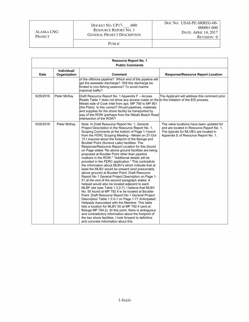
ALASKA LNG PROJECT
DOCKET NO. CP17-___-000 RESOURCE REPORT NO. 1
GENERAL PROJECT DESCRIPTION
DOC NO: USAI-PE-SRREG-00-000001-000
DATE: APRIL 14, 2017 REVISION: 0
PUBLIC
1-lxxiv
Resource Report No. 1 Public Comments
Date Individual/
Organization Comment Response/Resource Report Location of the offshore pipeline? Which end of the pipeline will get the seawater discharge? Will this discharge be limited to non-fishing seasons? To avoid marine mammal traffic?
9/29/2016 Peter McKay Draft Resource Report No. 1 Appendix F – Access Roads Table 1 does not show any access roads on the Nikiski side of Cook Inlet from apx. MP 790 to MP 801 (the Plant). Is this correct? Would pipelines, materials and supplies for the shore facility be transported by way of the ROW (perhaps from the Niksiki Beach Road intersection of the ROW?
The Applicant will address this comment prior to the initiation of the EIS process.
9/29/2016 Peter McKay Note: In Draft Resource Report No. 1, General Project Description in the Resource Report No. 1, Scoping Comments at the bottom of Page 1-1xxxvii from the FERC Scoping Meeting - Nikiski on 27-Oct-15 I inquired about the footprint of the Beluga and Boulder Point (Suneva Lake) facilities. The Response/Resource Report Location for this (found on Page states “No above ground facilities are being proposed at Boulder Point other than pipeline markers in the ROW.” “Additional details will be provided in the FERC application.” This contradicts the information about MLBV's which indicate that at least the MLBV would be present (and presumably above ground) at Boulder Point. Draft Resource Report No 1 General Project Description on Page 1-51 at the end of the second paragraph states: A helipad would also be located adjacent to each MLBF site (see Table 1.3.2-7). I believe that MLBV No. 50 found at MP 792.4 is be located at Boulder Point. Draft Resource Report No 1 General Project Description Table 1.3.5-1 on Page 1-77 Anticipated Helipads Associated with the Mainline. This table lists a location for MLBV 50 at MP 792.4 (and at Beluga MP 764.2). At this point, there is ambiguous and contradictory information about the footprint of the two shore facilities. I look forward to definitive and concrete information about this.
The valve locations have been updated for and are located in Resource Report No. 1. The typicals for MLVB's are located in Appendix E of Resource Report No. 1.

ALASKA LNG PROJECT
DOCKET NO. CP17-___-000 RESOURCE REPORT NO. 1
GENERAL PROJECT DESCRIPTION
DOC NO: USAI-PE-SRREG-00-000001-000
DATE: APRIL 14, 2017 REVISION: 0
PUBLIC
lxxv
TABLE OF CONTENTS
1.0 RESOURCE REPORT NO. 1 – GENERAL PROJECT DESCRIPTION ............................ 1-1 1.1 PROJECT DESCRIPTION .......................................................................................... 1-1 1.2 PROJECT PURPOSE AND NEED ............................................................................. 1-4 1.3 LOCATION AND DESCRIPTION OF FACILITIES ............................................... 1-5
1.3.1 Liquefaction Facility ........................................................................................... 1-6 1.3.1.1 LNG Plant ............................................................................................ 1-7 1.3.1.2 Marine Terminal ................................................................................ 1-11 1.3.1.3 Utilities/Supporting Systems ............................................................. 1-15 1.3.1.4 Associated Infrastructure ................................................................... 1-19 1.3.1.5 Temporary Facilities Associated with the Construction of the
Liquefaction Facility ......................................................................... 1-22 1.3.2 Interdependent Project Facilities....................................................................... 1-28
1.3.2.1 Mainline ............................................................................................. 1-28 1.3.2.2 Prudhoe Bay Gas Transmission Line (PBTL) ................................... 1-42 1.3.2.3 Point Thomson Gas Transmission Line (PTTL) ................................ 1-42 1.3.2.4 Temporary Pipeline Construction Infrastructure ............................... 1-44 1.3.2.5 Mainline Block Valves (MLBVs) ...................................................... 1-51 1.3.2.6 Launchers/Receivers .......................................................................... 1-53 1.3.2.7 Cathodic Protection Facilities ............................................................ 1-54 1.3.2.8 Gas Treatment Plant (GTP) ............................................................... 1-55
1.3.3 Project Meter Stations ....................................................................................... 1-71 1.3.4 Project Access Roads ........................................................................................ 1-72
1.3.4.1 Liquefaction Facility Access Roads ................................................... 1-72 1.3.4.2 Pipeline Access Roads ....................................................................... 1-73 1.3.4.3 GTP Access Roads ............................................................................. 1-73
1.3.5 Project Helipads ................................................................................................ 1-76 1.3.6 Project Airstrips ................................................................................................ 1-78 1.3.7 Project Material Sites ........................................................................................ 1-80
1.3.7.1 Liquefaction Facility .......................................................................... 1-80 1.3.7.2 Pipeline Material Sites ....................................................................... 1-81 1.3.7.3 GTP Material Site .............................................................................. 1-81
1.3.8 Project Waste Management .............................................................................. 1-81 1.3.8.1 Liquefaction Facility Waste Management ......................................... 1-82 1.3.8.2 Pipeline Waste Management.............................................................. 1-83 1.3.8.3 GTP Waste Management ................................................................... 1-83
1.3.9 Non-jurisdictional Facilities ............................................................................. 1-83 1.3.9.1 Connected Actions Assessment ......................................................... 1-84 1.3.9.2 PTU Expansion Project ...................................................................... 1-86 1.3.9.3 PBU Major Gas Sales (MGS) Project ................................................ 1-91 1.3.9.4 Kenai Spur Highway Relocation Project ........................................... 1-95
1.4 LAND REQUIREMENTS .......................................................................................... 1-95 1.4.1 Liquefaction Facility ......................................................................................... 1-99
1.4.1.1 LNG Plant .......................................................................................... 1-99

ALASKA LNG PROJECT
DOCKET NO. CP17-___-000 RESOURCE REPORT NO. 1
GENERAL PROJECT DESCRIPTION
DOC NO: USAI-PE-SRREG-00-000001-000
DATE: APRIL 14, 2017 REVISION: 0
PUBLIC
1-lxxvi
1.4.1.2 Marine Terminal ................................................................................ 1-99 1.4.2 Interdependent Project Facilities..................................................................... 1-106
1.4.2.1 Pipeline Facilities ............................................................................. 1-106 1.4.2.2 Pipeline Aboveground Facilities ...................................................... 1-111 1.4.2.3 Pipeline Associated Infrastructure ................................................... 1-112 1.4.2.4 GTP .................................................................................................. 1-113
1.5 CONSTRUCTION SCHEDULE, PROCEDURES, AND WORKFORCE .......... 1-115 1.5.1 Project Construction Schedule ........................................................................ 1-115
1.5.1.1 Liquefaction Facility Construction Schedule ................................... 1-118 1.5.1.2 Mainline Construction Schedule ...................................................... 1-119 1.5.1.3 GTP Construction Schedule ............................................................. 1-119 1.5.1.4 PBTL and PTTL Construction Schedule ......................................... 1-120 1.5.1.5 Non-jurisdictional Facilities Construction ....................................... 1-120
1.5.2 Project Construction Procedures ..................................................................... 1-120 1.5.2.1 Construction Logistics ..................................................................... 1-122 1.5.2.2 Liquefaction Facility Construction Procedures................................ 1-129 1.5.2.3 Onshore Pipeline Construction Execution and Procedures .............. 1-141 1.5.2.4 GTP Construction Procedures.......................................................... 1-187 1.5.2.5 Associated Infrastructure ................................................................. 1-188
1.5.3 Construction Workforce ................................................................................. 1-191 1.5.3.1 Liquefaction Facility ........................................................................ 1-191 1.5.3.2 Interdependent Project Facilities ...................................................... 1-191
1.5.4 Environmental Compliance, Training, and Inspection Program ..................... 1-192 1.5.5 Public Awareness Program ............................................................................. 1-193
1.6 OPERATIONS AND MAINTENANCE .................................................................. 1-194 1.6.1 Liquefaction Facility ....................................................................................... 1-194
1.6.1.1 Water Use during LNG Operations ................................................. 1-195 1.6.1.2 LNG Marine Operations .................................................................. 1-195
1.6.2 Interdependent Project Facilities..................................................................... 1-196 1.6.2.1 Pipeline Facilities ............................................................................. 1-196 1.6.2.2 Pipeline Aboveground Facilities ...................................................... 1-199 1.6.2.3 GTP .................................................................................................. 1-200
1.7 FUTURE PLANS AND ABANDONMENT ............................................................ 1-201 1.8 PERMITS AND APPROVALS ................................................................................ 1-201 1.9 AGENCY, PUBLIC, AND OTHER STAKEHOLDER COMMUNICATIONS . 1-201 1.10 LIST OF LANDOWNERS ........................................................................................ 1-201 1.11 CUMULATIVE IMPACTS ...................................................................................... 1-202
LIST OF TABLES
TABLE 1.3.1-2 Vessel Types and Characteristics Used for MOF Design ............................................. 1-15 TABLE 1.3.2-1 Mainline Route Summary for a 42-inch Pipeline ......................................................... 1-29 TABLE 1.3.2-2 Collocated ROWs with the Mainline (within 500 feet) ................................................ 1-30 TABLE 1.3.2-3 Gas Quality Limits ........................................................................................................ 1-31 TABLE 1.3.2-4 Pipeline Design – Mainline Segments .......................................................................... 1-32 TABLE 1.3.2-5 Preliminary Design Parameters .................................................................................... 1-33

ALASKA LNG PROJECT
DOCKET NO. CP17-___-000 RESOURCE REPORT NO. 1
GENERAL PROJECT DESCRIPTION
DOC NO: USAI-PE-SRREG-00-000001-000
DATE: APRIL 14, 2017 REVISION: 0
PUBLIC
1-lxxvii
TABLE 1.3.2-6 Preliminary Locations of Pipeline Aboveground Facility Stations .............................. 1-36 TABLE 1.3.2-7 Estimated Diesel Fuel Demand for Mainline and Aboveground Facility
Constructiona ............................................................................................................................... 1-46 TABLE 1.3.2-8 Estimated Number of Diesel Storage Tanksa for Mainline Construction...................... 1-47 TABLE 1.3.2-9 Estimated Number of Gasoline Storage Tanksa for Mainline Construction ................. 1-47 TABLE 1.3.2-10 Preliminary Pipeline Construction Camps, Pipe Storage Areas, Contractor Yards,
and Rail Spurs ............................................................................................................................ 1-48 TABLE 1.3.2-12 Estimated GTP Fuel Systems Storage Size ................................................................ 1-65 TABLE 1.3.2-13 Pipeline Construction ROW Ice Roads....................................................................... 1-75 TABLE 1.3.6-1 Airstrips Under Evaluation by the Project .................................................................... 1-79 TABLE 1.4-1 Estimated Land Required for Construction and Operation of the Project by Facility
Type ............................................................................................................................................ 1-97 TABLE 1.4.1-1 Terminal MOF Dredge Information ........................................................................... 1-103 TABLE 1.4.1-2 Duration of Dredging and Pile Driving Construction Activities ................................ 1-104 TABLE 1.4.2-1 Typical Pipeline Construction Right-of-Way Configurations .................................... 1-107 TABLE 1.4.2-2 Typical ATWS Dimensions Associated with the Pipeline Facilities .......................... 1-108 TABLE 1.5.2-1 Existing Highway Routes Anticipated to be Used by the Project ............................... 1-125 TABLE 1.5.2-2 Preliminary Construction Spreads for the Mainline ................................................... 1-143 TABLE 1.5.2-4 Construction Spread by Season and Location ............................................................ 1-150 TABLE 1.5.2-5 Preliminary Construction Spreads for the PTTL ........................................................ 1-167 TABLE 1.5.2-6 Mainline Pipe Weights ................................................................................................ 1-171 TABLE 1.5.2-7 Summary of Excavation at Shore Crossings (Onshore).............................................. 1-183 TABLE 1.5.2-8 Summary of Offshore Trenching ................................................................................ 1-184 LIST OF FIGURES
Figure 1.1-1 Project Facilities Overview ................................................................................................. 1-3 Figure 1.3.1-1 Lng Plant Overview .......................................................................................................... 1-8 Figure 1.3.1-2 Liquefaction Process Block Diagram .............................................................................. 1-10 Figure 1.3.1-3 Marine Terminal .............................................................................................................. 1-14 Figure 1.3.2-1 Flow Schematic For Compressor Station With Gas-To-Gas Cooling ............................. 1-38 Figure 1.3.2-2 Range Of Gas Temperatures ........................................................................................... 1-40 Figure 1.3.2-3 Gtp Facilities Overview .................................................................................................. 1-57 Figure 1.3.2-4 Gtp Pad Overview .......................................................................................................... 1-58 Figure 1.3.2-5 Gtp Process Block Diagram Of A Gtp Train .................................................................. 1-59 Figure 1.3.9-1 Ptu Facilities .................................................................................................................... 1-89 Figure 1.3.9-2 Pbu Mgs Facilities ........................................................................................................... 1-94 Figure 1.3.9-3 Kenai Spur Highway Relocation Routes Being Analyzed .............................................. 1-96 Figure 1.4.1-1 Terminal Mof Dredge Footprint .................................................................................... 1-102 Figure 1.4.1-2 Terminal Mof Dredge Template.................................................................................... 1-103 Figure 1.4.1-3 Mof Dredge Material Disposal Location ....................................................................... 1-105 Figure 1.4.1-4 Mof Dredge Material Disposal Alternatives ................................................................. 1-106 Figure 1.5.2-1 Construction Of The Marine Terminal – Proposed Dredged Material Disposal Sites .. 1-142 Figure 1.5.2-1a Summer Versus Winter Construction Sections Along The Mainline ........................... 1-148 Figure 1.5.2-1b Summer Versus Winter Construction Sections Along The Mainline .......................... 1-149

ALASKA LNG PROJECT
DOCKET NO. CP17-___-000 RESOURCE REPORT NO. 1
GENERAL PROJECT DESCRIPTION
DOC NO: USAI-PE-SRREG-00-000001-000
DATE: APRIL 14, 2017 REVISION: 0
PUBLIC
1-lxxviii
LIST OF APPENDICES
APPENDIX A Aerial Imagery and USGS Mapping of Preliminary Facility Locations (Provided under Separate Cover)
APPENDIX B Plot Plans of Proposed Aboveground Facilities (Provided under Separate Cover) APPENDIX C Federal, State, and Local Authorizations Anticipated for the Project APPENDIX D Summary of Public, Agency, and Stakeholder Engagement and Correspondence APPENDIX E Typical Drawings APPENDIX F Access Roads APPENDIX G Rationale for the Selection of Pipeline ROW Width APPENDIX H Specific Designs for Major Highway, Railroad, and TAPS Crossings APPENDIX I Construction Camps, Storage Areas, and Contractor Yards APPENDIX J Additional Temporary Workspace Areas APPENDIX K Landowner List (Privileged & Confidential) APPENDIX L Cumulative Impacts APPENDIX M Pipeline Winter and Permafrost Construction Plan APPENDIX N Mainline and PTTL Collocation Opportunities by Milepost

ALASKA LNG PROJECT
DOCKET NO. CP17-___-000 RESOURCE REPORT NO. 1
GENERAL PROJECT DESCRIPTION
DOC NO: USAI-PE-SRREG-00-000001-000
DATE: APRIL 14, 2017 REVISION: 0
PUBLIC
lxxix
ACRONYMS AND ABBREVIATIONS
ABBREVIATION DEFINITION
Abbreviations for Units of Measurement °F degrees Fahrenheit
BSCF/D billion standard cubic feet per day
BTU British Thermal Unit
BBtu/h billion British Thermal Units per hour
Hz hertz
kV kilovolt
μg microgram
MMSCF million standard cubic feet
MMSCF/D million standard cubic feet per day
MMTPA million metric tons per annum
MVA megavolt ampere
MW megawatt
nm nanometer
ppm parts per million
ppmv parts per million by volume
Psi pounds per square inch
psig pounds per square inch gauge Other Abbreviations 3LPE three-layer polyethylene ADEC Alaska Department of Environmental Conservation ADF&G Alaska Department of Fish and Game ADNR Alaska Department of Natural Resources ADOT&PF Alaska Department of Transportation and Public Facilities AGDC Alaska Gasline Development Corporation AGI Apex Gas Injection AGRU acid gas removal unit Applicant’s Plan Applicant’s Upland Erosion Control, Revegetation, and Maintenance Plan Applicant’s Procedures Applicant’s Wetland and Waterbody Construction, and Mitigation Procedures AOG Air Operations Guide AOGCC Alaska Oil and Gas Conservation Commission APCI Air Products and Chemicals Inc.
APDES Alaska Pollutant Discharge Elimination System
API American Petroleum Institute
Applicant Alaska Gasline Development Corporation ARRC Alaska Railroad Corporation ASME American Society of Mechanical Engineers
ATWS additional temporary workspace
BMP best management practice

ALASKA LNG PROJECT
DOCKET NO. CP17-___-000 RESOURCE REPORT NO. 1
GENERAL PROJECT DESCRIPTION
DOC NO: USAI-PE-SRREG-00-000001-000
DATE: APRIL 14, 2017 REVISION: 0
PUBLIC
lxxx
ABBREVIATION DEFINITION
BOG boil-off-gas
C.F.R. Code of Federal Regulations
CEQ Council on Environmental Quality
CGF Prudhoe Bay Unit Central Gas Facility
CO2 carbon dioxide
CP cathodic protection
CPF Central Processing Facility
DF design factor
DGGS Alaska Department of Natural Resources Division of Geological and Geophysical Surveys
DH dock head
DMLW Alaska Department of Natural Resources Division of Mining, Land, & Water
DMT direct microtunneling
DNPP Denali National Park and Preserve
DOE United States Department of Energy
DPOR Alaska Department of Natural Resources Division of Parks and Outdoor Recreation
EIS Environmental Impact Statement
EPA United States Environmental Protection Agency
FAA United States Department of Transportation, Federal Aviation Administration
FGL Fuel Gas Line
FBE fusion bonded epoxy
FERC United States Department of Energy, Federal Energy Regulatory Commission
FERC Plan FERC Upland Erosion Control, Revegetation, and Maintenance Plan
FERC Procedures FERC Wetland and Waterbody Construction and Mitigation Procedures
FTA Free Trade Agreement
GC1 Gathering Center #1
GTP gas treatment plant
H2S hydrogen sulfide
HDD horizontal directional drill
HIPPS high integrity pressure protective system
HP high pressure
IC Impressed Current
IPS Initial Production System ISO International Standardization Organization LACT lease automatic custody transfer LED light-emitting diode Liquefaction Facility natural gas liquefaction facility
LNG liquefied natural gas
LNGC liquefied natural gas carrier
Lo-Lo Lift-on/Lift-Off

ALASKA LNG PROJECT
DOCKET NO. CP17-___-000 RESOURCE REPORT NO. 1
GENERAL PROJECT DESCRIPTION
DOC NO: USAI-PE-SRREG-00-000001-000
DATE: APRIL 14, 2017 REVISION: 0
PUBLIC
lxxxi
ABBREVIATION DEFINITION
LP low pressure
Mainline An approximately 807-mile-long, large-diameter gas pipeline
MAOP maximum allowable operating pressure
MCHE main cryogenic heat exchanger
MGS Major Gas Sales
MLBV Mainline block valve
MLLW Mean Lower Low Water
MOF material offloading facility
MOP maximum operating pressure
MP Mainline milepost
NACE National Association of Corrosion Engineers NEPA National Environmental Policy Act NFPA National Fire Protection Association NGA Natural Gas Act
NMFS National Oceanographic and Atmospheric Administration, National Marine Fisheries Service
NOAA National Oceanographic and Atmospheric Administration
North Slope Alaska North Slope
NPDES National Pollutant Discharge Elimination System
NRO Alaska Department of Natural Resources Division of Mining, Land, & Water, Northern Region Office
NSA Noise Sensitive Area
NSB North Slope Borough
NVIC Navigation and Vessel Inspection Circular
Off-ROW Work areas located off the construction right-of-way
OSHA Occupational Safety and Health Administration
PBTL Prudhoe Bay Gas Transmission Line
PBU Prudhoe Bay Unit
PHMSA United States Department of Transportation, Pipeline and Hazardous Materials Safety Administration
PLF product loading facility
Project Alaska LNG Project
PSY Pipe Storage Yard
PTEP Point Thomson Expansion Project
PTTL Point Thomson Gas Transmission Line
PTU Point Thomson Unit
RCRA Resource Conservation and Recovery Act
Ro-Ro Roll-on/Roll-Off
ROW right-of-way
SAWL longitudinally submerged arc-welded pipe

ALASKA LNG PROJECT
DOCKET NO. CP17-___-000 RESOURCE REPORT NO. 1
GENERAL PROJECT DESCRIPTION
DOC NO: USAI-PE-SRREG-00-000001-000
DATE: APRIL 14, 2017 REVISION: 0
PUBLIC
lxxxii
ABBREVIATION DEFINITION
SCRO Alaska Department of Natural Resources Division of Mining, Land, & Water, Southcentral Region Office
SHPO Office of History and Archaeology, State Historic Preservation Office
SimOps Simultaneous Operations
SMYS Specified Minimum Yield Strength
SPCC Spill Prevention, Control, and Countermeasure
SPCS State Pipeline Coordinator’s Section
SPMT self-propelled module transporter
STP Seawater Treatment Plant
SWAPA Southwest Alaska Pilots Association
SWPPP Stormwater Pollution Prevention Plan
TAPS Trans-Alaska Pipeline System
TBD To be determined
UIC Underground Injection Control
UL Underwriters Laboratories
U.S. United States
USACE United States Army Corps of Engineers
USCG United States Coast Guard
USDOI United States Department of the Interior
USDOT United States Department of Transportation
USFWS United States Department of the Interior, United States Fish and Wildlife Service
USGS United States Geological Survey
VSM vertical support member
WDAP Wastewater Discharge Authorization Program
WHRU waste heat recovery unit
WSA Waterway Suitability Assessment

ALASKA LNG PROJECT
DOCKET NO. CP17-___-000 RESOURCE REPORT NO. 1
GENERAL PROJECT DESCRIPTION
DOC NO: USAI-PE-SRREG-00-000001-000
DATE: APRIL 14, 2017 REVISION: 0
PUBLIC
1-1
1.0 RESOURCE REPORT NO. 1 – GENERAL PROJECT DESCRIPTION
1.1 PROJECT DESCRIPTION
The Alaska Gasline Development Corporation (Applicant) plans to construct one integrated liquefied natural gas (LNG) Project (Project) with interdependent facilities for the purpose of liquefying supplies of natural gas from Alaska, in particular from the Point Thomson Unit (PTU) and Prudhoe Bay Unit (PBU) production fields on the Alaska North Slope (North Slope), for export in foreign commerce and for in-state deliveries of natural gas.
The Natural Gas Act (NGA), 15 U.S.C. § 717a (11) (2006), and Federal Energy Regulatory Commission (FERC) regulations, 18 Code of Federal Regulations (C.F.R.) § 153.2(d) (2014), define “LNG terminal” to include “all natural gas facilities located onshore or in State waters that are used to receive, unload, load, store, transport, gasify, liquefy, or process natural gas that is ... exported to a foreign country from the United States.” With respect to this Project, the “LNG Terminal” includes the following: a liquefaction facility (Liquefaction Facility) in Southcentral Alaska; an approximately 807-mile gas pipeline (Mainline); a gas treatment plant (GTP) within the PBU on the North Slope; an approximately 63-mile gas transmission line connecting the GTP to the PTU gas production facility (PTU Gas Transmission Line or PTTL); and an approximately 1-mile gas transmission line connecting the GTP to the PBU gas production facility (PBU Gas Transmission Line or PBTL). All of these facilities are essential to export natural gas in foreign commerce and will have a nominal design life of 30 years.
These components are shown in Figure 1.1-1, as well as the maps found in Appendices A and B. Their proposed basis for design is described as follows.
The new Liquefaction Facility would be constructed on the eastern shore of Cook Inlet just south of the existing Agrium fertilizer plant on the Kenai Peninsula, approximately 3 miles southwest of Nikiski and 8.5 miles north of Kenai. The Liquefaction Facility would include the structures, equipment, underlying access rights, and all other associated systems for final processing and liquefaction of natural gas, as well as storage and loading of LNG, including terminal facilities and auxiliary marine vessels used to support Marine Terminal operations (excluding LNG carriers [LNGCs]). The Liquefaction Facility would include three liquefaction trains combining to process up to approximately 20 million metric tons per annum (MMTPA) of LNG. Two 240,000-cubic-meter tanks would be constructed to store the LNG. The Liquefaction Facility would be capable of accommodating two LNGCs. The size of LNGCs that the Liquefaction Facility would accommodate would range between 125,000–216,000-cubic-meter vessels.
In addition to the Liquefaction Facility, the LNG Terminal would include the following interdependent facilities:
Mainline: A new 42-inch-diameter natural gas pipeline approximately 807 miles in length would extend from the Liquefaction Facility to the GTP in the PBU, including the structures, equipment, and all other associated systems. The proposed design anticipates up to eight compressor stations; one standalone heater station, one heater station collocated with a compressor station, and six cooling stations associated with six of the compressor stations; four meter stations; 30 Mainline block valves (MLBVs); one pig launcher facility at the GTP meter station, one pig receiver facility at the Nikiski meter station, and combined pig launcher and receiver facilities at each of the compressor stations; and associated infrastructure facilities.

ALASKA LNG PROJECT
DOCKET NO. CP17-___-000 RESOURCE REPORT NO. 1
GENERAL PROJECT DESCRIPTION
DOC NO: USAI-PE-SRREG-00-000001-000
DATE: APRIL 14, 2017 REVISION: 0
PUBLIC
1-2
Associated infrastructure facilities would include additional temporary workspace (ATWS), access roads, helipads, construction camps, pipe storage areas, material extraction sites, and material disposal sites.
Along the Mainline route, there would be at least five gas interconnection points to allow for future in-state deliveries of natural gas. The approximate locations of three of the gas interconnection points have been tentatively identified as follows: milepost (MP) 441 to serve Fairbanks, MP 763 to serve the Matanuska-Susitna Valley and Anchorage, and MP 807 to serve the Kenai Peninsula. The size and location of the other interconnection points are unknown at this time. None of the potential third-party facilities used to condition, if required, or move natural gas away from these gas interconnection points are part of the Project. Potential third-party facilities are addressed in the Cumulative Impacts analysis found in Appendix L;
GTP: A new GTP and associated facilities in the PBU would receive natural gas from the PBU Gas Transmission Line and the PTU Gas Transmission Line. The GTP would treat/process the natural gas for delivery into the Mainline. There would be custody transfer, verification, and process metering between the GTP and PBU for fuel gas, propane makeup, and byproducts. All of these would be on the GTP or PBU pads;
PBU Gas Transmission Line: A new 60-inch natural gas transmission line would extend approximately 1 mile from the outlet flange of the PBU gas production facility to the inlet flange of the GTP. The PBU Gas Transmission Line would include one meter station on the GTP pad; and
PTU Gas Transmission Line: A new 32-inch natural gas transmission line would extend approximately 63 miles from the outlet flange of the PTU gas production facility to the inlet flange of the GTP. The PTU Gas Transmission Line would include one meter station on the GTP pad, four MLBVs, and pig launcher and receiver facilities—one each at the PTU and GTP pads.
Existing State of Alaska transportation infrastructure would be used during the construction of these new facilities including ports, airports, roads, railroads, and airstrips (potentially including previously abandoned airstrips). A preliminary assessment of potential new infrastructure and modifications or additions to these existing in-state facilities is provided in Appendix L. The Liquefaction Facility, Mainline, and GTP would require the construction of modules that may or may not take place at existing or new manufacturing facilities in the United States.
Appendix A contains maps of the Project footprint. Appendices B and E depict the footprint, plot plans of the aboveground facilities, and typical layout of aboveground facilities.
Outside the scope of the Project, but in support of or related to the Project, additional facilities or expansion/modification of existing facilities would be needed to be constructed. These other projects may include:
Modifications/new facilities at the PTU (PTU Expansion project); Modifications/new facilities at the PBU (PBU Major Gas Sales [MGS] project); and Relocation of the Kenai Spur Highway.

!
!
!
!
!
!
!
!
!
!
")")
")
")
")
")
")
")
")
")
")
")
Tetlin NationalWildlife Refuge
Arctic NationalWildlife Refuge
Yukon FlatsNational Wildlife RefugeSelawik National
WildlifeRefuge Kanuti National
Wildlife Refuge
Koyukuk NationalWildlifeRefuge
NoatakNationalPreserve
Gates of the ArcticNational Park & Preserve
Yukon DeltaNational
Wildlife Refuge
Yukon-CharleyRivers National
Preserve
Lake ClarkNational Park
& Preserve
CapeKrusenstern
NationalMonument Kobuk Valley
National Park
Bering LandBridge National
Preserve
NowitnaNational
Wildlife Refuge
Innoko NationalWildlife Refuge
Kenai NationalWildlife Refuge
Wrangell-St.EliasNational Park
& Preserve
ChugachNationalForest
Denali NationalPark & Preserve
Steese NationalConservation Area
NationalPetroleum Reserve
Nelchina PublicUse Area
Minto Flats StateGame Refuge
Tanana ValleyState Forest
PT THOMSONFACILITY
GTPFACILITY
LIQUEFACTIONFACILITY
PT THOMSON TRANSMISSIONPIPELINE
MAINLINE
B e a u f o r t S e a
G u l f o f A l a s k a
PrinceWilliamSound
Cook
Inle t
RAY RIVERCOMPRESSOR
STATION
THEODORE RIVERHEATER STATION
SAGWONCOMPRESSORSTATION
GALBRAITH LAKECOMPRESSORSTATION
COLDFOOTCOMPRESSORSTATION
MINTOCOMPRESSORSTATION
HEALYCOMPRESSOR
STATION
HONOLULU CREEKCOMPRESSORSTATION
RABIDEUX CREEKCOMPRESSOR
STATION
PorcupineSusitna
Colville
Koyukuk
Tanana
Kuskokwim
Yukon
PARK
S HIGHW
AY
DALTON HIGHWAY
NIKISKI
ANCHORAGE
TALKEETNA
COLDFOOT
VALDEZ
TOK
LIVENGOOD
DELTAJUNCTION
BARROW
CA
NA
DA
AL A
S KA
LEGEND
0 50 100 Miles
PROJECT FACILITIESOVERVIEW
!°
SCALE:1 of 1
AGDCPREPARED BY:1:6,000,000
2017-03-01 SHEET:DATE:X:\AKLNG\Resource Reports\RR01\Figure 1_1_1 Project Facilities.mxd
FIGURE 1.1-1!
!
!
CANADARUSSIA
Arctic Ocean
Pacific Ocean
Bering Sea ANCHORAGE
FAIRBANKS
PRUDHOE BAY
VICINITY MAP DISCLAIMERThe information contained herein is for informational or planning purposes only, It does not nor should it be deemed to be an offer, request or proposals for rights or occupation of any kind. The Alaska LNG Project Participants and their respective officers, employees and agents, make no warranty, implied or otherwise, nor accept any liability, as to the accuracy or completeness of the information contained inthese documents, drawings or electronic files. Do not removeor delete this note from document, drawing or electronic file.
") Project Facility") Existing Facility! Alaska Place Names
Alaska LNG Rev C2 Route
Major HighwaysMajor RiversState and FederalConservation Lands

ALASKA LNG PROJECT
DOCKET NO. CP17-___-000 RESOURCE REPORT NO. 1
GENERAL PROJECT DESCRIPTION
DOC NO: USAI-PE-SRREG-00-000001-000
DATE: APRIL 14, 2017 REVISION: 0
PUBLIC
1-4
1.2 PROJECT PURPOSE AND NEED
The purpose of the Alaska LNG Project (Project) is to commercialize the vast natural gas resources2 on Alaska’s North Slope, principally by converting the available natural gas supply to LNG for export. There have been numerous unsuccessful efforts to bring this gas to market, including past projects to transport gas by pipeline to the continental United States.3 As indigenous Lower 48 natural gas supply has increased, an interstate pipeline project from Alaska is currently not economically viable. Foreign demand for natural gas has increased,4 making LNG export the best and only viable option to commercialize these abundant Alaskan resources at this time.
The Project’s intention is to deliver natural gas from the PBU and PTU, which is a subset of total North Slope resources.5 The U.S. Department of Energy (DOE) has conditionally approved an application for the Project to export 20 million metric tons per annum of LNG produced from Alaska for a 30-year period to Free Trade Agreement (FTA) or non-FTA nations.6 Yet no infrastructure exists to deliver this natural gas to market.
Taking these and other factors into account, including economics, technical requirements and environmental considerations,7 the Applicant, determined the location, throughput, and timing for the Project. A new LNG terminal8 to export up to 20 MMTPA of LNG,9 with projected startup in approximately 2024-2025, would include year-round accessible marine facilities near Nikiski, Alaska,10 as well as liquefaction, pipeline, and gas treatment facilities, connecting North Slope natural gas to foreign LNG markets. This integrated LNG terminal would be the largest LNG project constructed in the United States, with an estimated cost of $40 to $45 billion.
2 See DeGolyer and MacNaughton, “Report on a Study of Alaska Gas Reserves and Resources for Certain Gas Supply Scenarios as of December 31, 2012” at Figure 5 (April 2014).
3 http://www.arlis.org/docs/vol1/AlaskaGas/Report/Report_CRS_2011_AK_NGP_IssuesCongress.pdf 4 https://www.mckinseyenergyinsights.com/insights/positive-outlook-for-lng.aspx 5 DeGolyer and MacNaughton at 11. 6 DOE/FE Order No. 3554 (granting authorization to export LNG to FTA nations); DOE/FE Order No. 3643 (granting authorization to export
LNG to non-FTA nations conditioned on FERC’s environmental review process). DOE’s non-FTA approval is conditioned on the satisfactory completion of the ongoing FERC-led National Environmental Policy Act (NEPA) review process, in which DOE is a cooperating agency. DOE Order No. 3643, at 9, 42.
7 See Resource Report No. 10 for a full discussion of the alternatives and reasons for selecting the Project. 8 See 18 C.F.R. 153.2(d)(defining “LNG terminal” to include “all natural gas facilities used to … transport, gasify, liquefy, or process natural gas
that is … exported to a foreign country from the United States”); supra Section 1.1. 9 DOE/FE Order No. 3554 and Order No. 3643. 10 Because the Project requires year-round LNG export by waterborne vessels, the purpose and need of the Project is water-dependent.

ALASKA LNG PROJECT
DOCKET NO. CP17-___-000 RESOURCE REPORT NO. 1
GENERAL PROJECT DESCRIPTION
DOC NO: USAI-PE-SRREG-00-000001-000
DATE: APRIL 14, 2017 REVISION: 0
PUBLIC
1-5
Several important objectives support this substantial investment. The Project would:
Commercialize natural gas resources on the North Slope during the economic life of the PBU field and achieve efficiencies through the use of existing common oil and gas infrastructure and economies of scale;
Bring cost-competitive Alaska LNG to foreign markets in a timely manner; and
Provide at least five interconnection points to allow for in-state gas deliveries, benefiting in-state gas users and supporting long-term economic development.11
In commercializing, North Slope natural gas, the Project would offer multiple benefits, all of which are consistent with the public interest. The Project would:
Stimulate local, state, regional, and national economies through job creation, an enhanced tax base, increased economic activity, and improved U.S. balance of trade, producing “unequivocally positive” economic impacts in Alaska and the United States as a whole;12
Provide a long-term source of revenue to Alaska state and local governments, supporting public services;
Create up to 15,160 jobs during peak construction and approximately 730 jobs for operation of the Project;
Create numerous opportunities for Alaska businesses and contractors during construction and operation of the Project;
Provide infrastructure that may provide opportunity for expansion and incentivize further investment, exploration, and production, leading to more industry activity in the state;
Support the economic and national security interests of the United States by providing a secure source of energy for its trading partners and contributing to the long-term stability of international energy supply; and
Produce local, regional, and global environmental benefits by providing, through natural gas and LNG, a cleaner source of energy than many existing alternatives.
1.3 LOCATION AND DESCRIPTION OF FACILITIES
An overview of the Project’s planned facilities and locations is provided as Figure 1.1-1. The proposed pipeline route (Revision C2), off-right-of-way (ROW) work areas, and locations of major facilities are
11 Id. (estimating demand for in-state use). 12 Id. at 4-5.

ALASKA LNG PROJECT
DOCKET NO. CP17-___-000 RESOURCE REPORT NO. 1
GENERAL PROJECT DESCRIPTION
DOC NO: USAI-PE-SRREG-00-000001-000
DATE: APRIL 14, 2017 REVISION: 0
PUBLIC
1-6
depicted on aerial imagery and U.S. Geological Survey (USGS) maps provided in Appendix A (map set A1 provides USGS base maps, A2 provides aerial base maps, and A3 includes USGS and aerial base maps of work areas located off the construction ROW [off-ROW] that do not fit into the view extent of A1 or A2). Preliminary plot plans of aboveground facilities are provided in Appendix B.
The Project is designed in accordance with applicable laws, regulations, and design codes and standards and with consideration for Alaska-specific conditions. Project design criteria incorporate consideration of a range of variable site conditions that could occur based upon historic information and future conditions. Mitigations are integrated into the design where appropriate or required for facility integrity and safe operations. Opportunities for adaptation and resilience13 to potential effects of climate change are included in these design considerations.
1.3.1 Liquefaction Facility
The Liquefaction Facility would be a new facility constructed on the eastern shore of Cook Inlet in the Nikiski area of the Kenai Peninsula, within the area depicted in the appendices. The proposed Liquefaction Facility would be approximately 921 acres (901 acres onshore and 20 acres offshore), approximately 3 miles from Nikiski, and 8.5 miles from Kenai.
The Liquefaction Facility would consist of the LNG Plant and Marine Terminal. A discussion of the LNG Plant and Marine Terminal is provided below. Associated utilities and supporting infrastructure facilities at the site are discussed in Sections 1.3.1.3 and 1.3.1.4, respectively. Temporary facilities associated with the construction of the Liquefaction Facility are discussed in Section 1.3.1.5.
The Liquefaction Facility design considers the following opportunities for adaptation and resilience:
Sea level changes – The design of the trestle height and facility elevation would account for potential, projected sea level changes (tectonic activity has changed the land surface over time) and extreme weather events;
Temperature – The design of the facility would account for seasonal temperature effects to the plant, plant performance, and material balances; and
Water supply – Forward-looking projections for potential changes in local water supplies and recharge rates would be taken into account for design considerations that affect water use requirements.
13 Adaptation –- Adaptation is an action that can be implemented as a response to changes in the climate to harness and leverage its beneficial opportunities; Resilience –- Resilience is the capability to anticipate, prepare for, respond to, and recover from significant multi-hazard threats with minimum damage to social well-being, the economy, and the environment (National Research Council. 2010. Adapting to the Impacts of Climate Change. The National Academies Press. 292 pp.).

ALASKA LNG PROJECT
DOCKET NO. CP17-___-000 RESOURCE REPORT NO. 1
GENERAL PROJECT DESCRIPTION
DOC NO: USAI-PE-SRREG-00-000001-000
DATE: APRIL 14, 2017 REVISION: 0
PUBLIC
1-7
1.3.1.1 LNG Plant
The LNG Plant would consist of three liquefaction processing units, called trains, that are jointly capable of producing up to 20 MMTPA of LNG. As depicted in Figure 1.3.1-1, the LNG Plant consists of the following main facilities:
Inlet and pre-treatment facilities; Liquefaction process facilities; and LNG storage tanks.
As described in the following section, LNG from the liquefaction facilities would be transferred to LNG storage tanks for subsequent delivery to LNGCs.
1.3.1.1.1 Inlet Receiving and Pre-Treatment Facilities
Natural gas treated by the GTP in the PBU and delivered to Nikiski via the Mainline would flow to the LNG Plant receipt point (plant inlet flange). High-pressure feed gas from the Mainline would enter the inlet facilities at normal inlet pressures of 1,050 to 1,250 pounds per square inch gauge (psig) and at 32 to 45 °F temperature. The natural gas would first be filtered, then heated in the inlet gas heater by steam, and then reduced in pressure through a pressure letdown station.
The feed gas (i.e., gas that is used as the raw material for an LNG plant) for the liquefaction trains would meet LNG processing specification requirements. Even though the quality of this natural gas exceeds pipeline specifications, small amounts of water and potential mercury would need to be removed prior to the liquefaction cooling process.
The natural gas pre-treatment system would consist of the following:
A mercury removal system would be located upstream of the molecular sieve dehydration beds. Although mercury is not expected, if present, it can cause irreparable damage to aluminum cryogenic equipment in the plant. Mercury absorbers would be used to strip any mercury found in the natural gas stream to the acceptable level (0.01 microgram/cubic nanometer [μg/Nm³])14. Specifically, the mercury removal system would be a common system based on three parallel vessels containing adsorbent material. Each vessel would handle one-third of the total feed gas flow. The expected design life for the mercury adsorbent beds is more than five years. The mercury guard bed would be monitored and repaired as needed and would be removed and disposed of by licensed company/professionals in an approved waste disposal facility. After exiting the mercury removal system, the natural gas would be filtered to remove carbon dust particles before being routed to dehydration beds; and
14 Mercury removed by the sulfur impregnated adsorbent is converted by the adsorbent to mercuric sulfide, a naturally occurring and stable compound. Spent adsorbent will be handled according to appropriate disposal procedures and according to applicable safety and transportation regulations.

Keystone Phase IV, US
Gas Line toInlet Treating
LNG Storage
PlantEntry
Ponds
NikiskiMeter
Station
Utilities
Power
Refrig. / Cond.Stg. & Loading
LP Flare
Ground Flare
FirewaterStorage
Heavy HaulRoad
Pond
Pond
Fractionationand Utilities
Train 1
Train 2
Train 3
PlantEntry
Operations/Admin. Building
and ControlRoom
Material OffloadingFacility
Inlet GasTreating/Fuel
0 500 1,000 Feet
LNG PLANTOVERVIEW
AGDC
LNG Property BoundaryLNG Facility FeaturesLNG Train 1LNG Train 2LNG Train 3
X:\AKLNG\Resource Reports\RR01\Figure 1_3_1_1 LNG Plant Overview.mxd
DISCLAIMER
PREPARED BY:
DATE: SHEET:
!°
1 of 1SCALE: 1:12,500
2017-02-27
The information contained herein is for informational or planning purposes only, It does not nor should it be deemed to be an offer, request or proposals for rights or occupation of any kind. The Alaska LNG Project Participants and their respective officers, employees and agents, make no warranty, implied or otherwise, nor accept any liability, as to the accuracy or completeness of the information contained inthese documents, drawings or electronic files. Do not removeor delete this note from document, drawing or electronic file.
!
!
!
CANADARUSSIA
Arctic Ocean
Pacific Ocean
Bering Sea ANCHORAGE
FAIRBANKS
PRUDHOE BAYVICINITY MAP
FIGURE 1.3.1-1
LEGEND
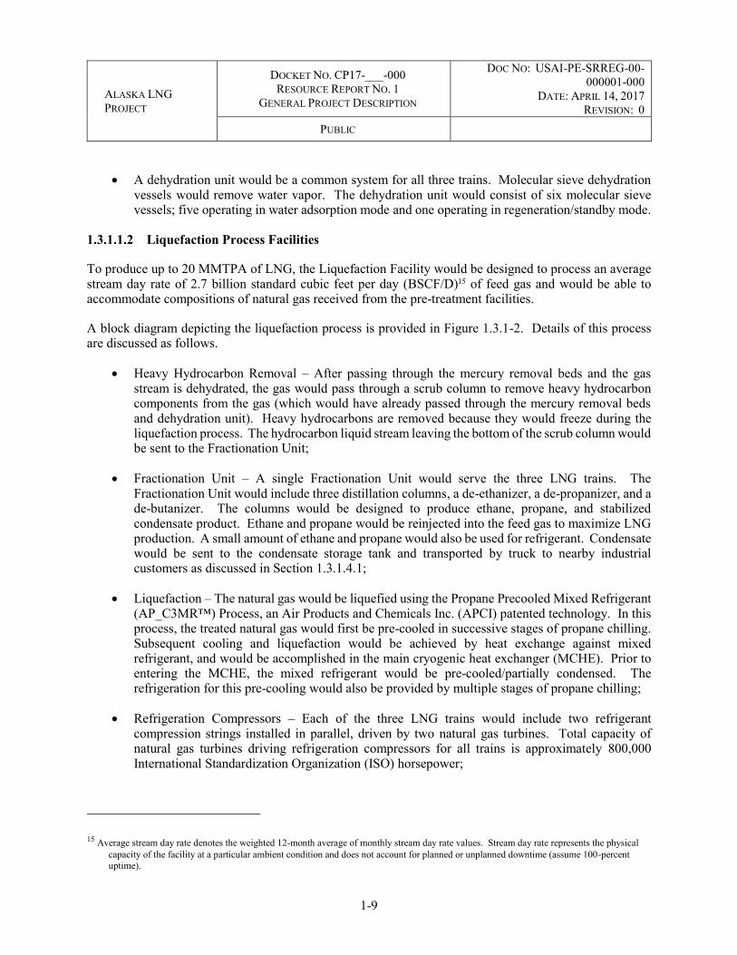
ALASKA LNG PROJECT
DOCKET NO. CP17-___-000 RESOURCE REPORT NO. 1
GENERAL PROJECT DESCRIPTION
DOC NO: USAI-PE-SRREG-00-000001-000
DATE: APRIL 14, 2017 REVISION: 0
PUBLIC
1-9
A dehydration unit would be a common system for all three trains. Molecular sieve dehydration vessels would remove water vapor. The dehydration unit would consist of six molecular sieve vessels; five operating in water adsorption mode and one operating in regeneration/standby mode.
1.3.1.1.2 Liquefaction Process Facilities
To produce up to 20 MMTPA of LNG, the Liquefaction Facility would be designed to process an average stream day rate of 2.7 billion standard cubic feet per day (BSCF/D)15 of feed gas and would be able to accommodate compositions of natural gas received from the pre-treatment facilities.
A block diagram depicting the liquefaction process is provided in Figure 1.3.1-2. Details of this process are discussed as follows.
Heavy Hydrocarbon Removal – After passing through the mercury removal beds and the gas stream is dehydrated, the gas would pass through a scrub column to remove heavy hydrocarbon components from the gas (which would have already passed through the mercury removal beds and dehydration unit). Heavy hydrocarbons are removed because they would freeze during the liquefaction process. The hydrocarbon liquid stream leaving the bottom of the scrub column would be sent to the Fractionation Unit;
Fractionation Unit – A single Fractionation Unit would serve the three LNG trains. The Fractionation Unit would include three distillation columns, a de-ethanizer, a de-propanizer, and a de-butanizer. The columns would be designed to produce ethane, propane, and stabilized condensate product. Ethane and propane would be reinjected into the feed gas to maximize LNG production. A small amount of ethane and propane would also be used for refrigerant. Condensate would be sent to the condensate storage tank and transported by truck to nearby industrial customers as discussed in Section 1.3.1.4.1;
Liquefaction – The natural gas would be liquefied using the Propane Precooled Mixed Refrigerant (AP_C3MR™) Process, an Air Products and Chemicals Inc. (APCI) patented technology. In this process, the treated natural gas would first be pre-cooled in successive stages of propane chilling. Subsequent cooling and liquefaction would be achieved by heat exchange against mixed refrigerant, and would be accomplished in the main cryogenic heat exchanger (MCHE). Prior to entering the MCHE, the mixed refrigerant would be pre-cooled/partially condensed. The refrigeration for this pre-cooling would also be provided by multiple stages of propane chilling;
Refrigeration Compressors – Each of the three LNG trains would include two refrigerant compression strings installed in parallel, driven by two natural gas turbines. Total capacity of natural gas turbines driving refrigeration compressors for all trains is approximately 800,000 International Standardization Organization (ISO) horsepower;
15 Average stream day rate denotes the weighted 12-month average of monthly stream day rate values. Stream day rate represents the physical capacity of the facility at a particular ambient condition and does not account for planned or unplanned downtime (assume 100-percent uptime).

ALASKA LNG PROJECT
DOCKET NO. CP17-___-000 RESOURCE REPORT NO. 1
GENERAL PROJECT DESCRIPTION
DOC NO: USAI-PE-SRREG-00-000001-000
DATE: APRIL 14, 2017 REVISION: 0
PUBLIC
1-10
Cooling System – The propane and mixed refrigerant would be cooled using air coolers. Fans would pull the air over tube bundles, in turn cooling within the tube bundles. The system would involve a number of electric motor and fan assemblies requiring a plant-wide total of approximately 29,000 brake horsepower. Air-cooled LNG plants are influenced by the variation in the air temperature. The Liquefaction Facility air cooler inlet air dry bulb design temperature would vary between a low ambient of 2 degrees Fahrenheit (°F) and a high ambient of 61 °F. Ambient temperatures affect production rates, resulting in a higher achievable liquefaction rate in the winter months than in the summer; and
Boil-off-gas (BOG) Compression – All BOG (i.e., vaporized LNG) generated from the LNG lines, LNG loading pumps, and storage tanks, plus vapor return from LNG loading operations would be compressed and routed to the fuel gas system. BOG generated in excess of fuel gas demand would be recycled to the natural gas stream entering the liquefaction process. BOG from the LNG storage tanks and loading berths would provide the majority of the overall plant fuel needs for operations.
FIGURE 1.3.1-2 Liquefaction Process Block Diagram

ALASKA LNG PROJECT
DOCKET NO. CP17-___-000 RESOURCE REPORT NO. 1
GENERAL PROJECT DESCRIPTION
DOC NO: USAI-PE-SRREG-00-000001-000
DATE: APRIL 14, 2017 REVISION: 0
PUBLIC
1-11
1.3.1.1.3 LNG Storage Tanks
LNG from the three liquefaction trains would be stored in two LNG storage tanks. Each of the tanks would be capable of storing approximately 240,000 cubic meters. The LNG storage tanks, capable of storing 480,000 cubic meters (total) would provide a storage capacity of three to four days of production. The tanks would be above ground, providing full containment, with the design consisting of a precast concrete inner tank with a 9-percent nickel bottom and a precast concrete outer tank.
The two LNG storage tanks would be located between the liquefaction trains and Marine Terminal. Siting of the tanks in this location (1) provides for the shortest distance for the cryogenic lines, (2) provides flexibility for trestle and liquefaction train locations, and (3) minimizes the likelihood of vapor dispersion toward the property boundary.
1.3.1.1.4 LNG Loading Lines
Loading and circulating piping, from the LNG storage tanks to the loading arm would transfer approximately 12,500 cubic meters of LNG per hour. The LNG loading system would consist of two parallel pipe-in-pipe lines each consisting of a 32-inch outer pipe and a 28-inch inner pipe. The outer pipe serves as a liquid and vapor containment system in the unlikely event of a leak from the inner pipe. A 36-inch vapor return line (not pipe-in-pipe) is also provided, carrying vapors from the LNGCs back to the BOG compressors. The loading system would be designed to load one LNGC at a time.
1.3.1.2 Marine Terminal
The Marine Terminal would be constructed adjacent to the LNG Plant in Cook Inlet and would allow LNGCs to dock and load LNG. As shown on Figure 1.3.1-3, marine facilities would include:
Product loading facility (PLF) that would support the piping that delivers LNG from shore to LNGCs and that would include all of the equipment to dock LNGCs; and
Material offloading facility (MOF) that would be a dock used during Project construction to enable direct deliveries of materials, equipment, modules, and other cargo to minimize the transport of large and heavy loads over road infrastructure.
The PLF would be a permanent facility for the duration of the LNG export operations. The MOF would consist of temporary facilities that would be removed during operations of the LNG Plant. As discussed in Section 1.4.1.2.1, the approach and berths at the MOF would need to be dredged to the depths of -30 feet and -32 feet Mean Lower Low Water (MLLW), respectively. An additional allowance of no more than -2 feet may be required for over-dredge.
The design loading rate is proposed to be 12,500 cubic meters of LNG per hour and the facilities would be designed for loading of one LNGC at a time. However, another LNGC may berth or unberth while loading operations are occurring at the other berth. Vessel refueling is not proposed during operations at the facility.
Loading berths would be designed for a range of LNGC sizes to accommodate specific marketing requirements. Based on a nominal 176,000-cubic-meter LNGC design vessel, approximately 21 vessel visits per month would be required to export the produced LNG. The LNGCs would range in size between

ALASKA LNG PROJECT
DOCKET NO. CP17-___-000 RESOURCE REPORT NO. 1
GENERAL PROJECT DESCRIPTION
DOC NO: USAI-PE-SRREG-00-000001-000
DATE: APRIL 14, 2017 REVISION: 0
PUBLIC
1-12
125,000 cubic meters (approximately 30 vessel visits per month) and 216,000 cubic meters (approximately 17 vessel visits per month). The Marine Terminal would be equipped with the appropriate aids to navigation.
1.3.1.2.1 Product Loading Facility
The PLF would consist of the following components that are depicted on Figure 1.3.1-3:
LNGCs would be moored at a berth, consisting of mooring and breasting dolphins and interconnecting walkways. The berths would be located in natural water depths greater than -53 feet MLLW and would be approximately 1,600 feet apart (the distance measured between the centerline of each berth, see Figure 1.3.1-3). The direction of the berth orientation would be with the predominant peak current direction for safe LNGC maneuvering and to minimize mooring loads while LNGCs are berthed. Each berth would include:
○ Four breasting dolphins that include marine fenders. Breasting dolphins assist moored LNGCs by absorbing loads generated by sea state conditions that are transmitted to the berth from the ship, as well as by serving as mooring points to restrict longitudinal movement of the vessel. The breasting dolphin structures would be supported by jacketed structures. The breasting dolphins would have a pre-cast concrete deck (platform) with railings for personnel engaged in the mooring process and emergency release mooring hooks and winch;
○ Six concrete pre-cast mooring dolphins with mooring hooks (three forward and three aft of the moored vessel at each berth). The mooring dolphins would be used to secure the vessel alongside the berth for cargo loading operations. The mooring dolphins would be supported by jacketed structures piled to the seabed. The mooring dolphins are accessible via walkways; and
○ Walkways for personnel access to breasting and mooring dolphins.
The access trestle would be a steel jacket structure with decking that would connect the storage tanks onshore to the loading platforms at the offshore end of the trestle. The loading platforms would be connected to each other and to the shore by means of a single trestle;
The trestle would be approximately 3,300 feet long and would support pipe rack modules and a roadway (side by side) from the shoreline to the loading platforms. The trestle support piles would be spaced at 120 feet, which corresponds to the maximum spacing practicable based on proposed engineering design. The roadway would be a one-lane, standard width of 15 feet with bypass bays (roadway width of 30 feet) at three locations along the trestle. The trestle would slope down from the top of bluff (approximately +116 MLLW) to the berths (approximately +50 MLLW), as measured from the top of the piles; and
The marine operations platform (see Figure 1.3.1-3) is a steel jacketed, pile-supported platform that would include the Marine Terminal Building; electrical substations; and supporting piping, cabling, and equipment used to monitor the loading operations. The marine operations platform

ALASKA LNG PROJECT
DOCKET NO. CP17-___-000 RESOURCE REPORT NO. 1
GENERAL PROJECT DESCRIPTION
DOC NO: USAI-PE-SRREG-00-000001-000
DATE: APRIL 14, 2017 REVISION: 0
PUBLIC
1-13
would have a preliminary design size of approximately 0.4 acre in surface area (approximately 200 feet by 60 feet) and the deck would be capable of supporting a variety of vehicles.
1.3.1.2.2 Marine Terminal Building
The Marine Terminal Building, located on the Marine Operations Platform, would contain the operational controls for marine facilities systems (e.g., quick release mooring hooks, marine loading arms, mooring tension monitoring, berthing systems, winch, and environmental monitoring system) including the ability to initiate loading shut-down in an emergency.
1.3.1.2.3 Temporary Material Offloading Facility
The MOF would enable direct delivery of cargos to the construction site. The cargos would include equipment modules, bulk construction materials, and construction equipment to support the construction of the Liquefaction Facility. Cargos would be unloaded at Roll-on/Roll-off (Ro-Ro) berth or at the Lift-on/Lift-off (Lo-Lo) berth. Direct delivery of modules is critical for maintaining the construction schedule, minimizing the number of vessels delivering materials to the site, and reducing the number of trucks on local roads and highways. The MOF would be designed as a temporary facility with a nominal design life of 10 years. The MOF would be removed early in operations when it is no longer needed to support construction of the Liquefaction Facility.
The MOF would consist of berths and laydown areas and be constructed of local fill materials with site-specific erosion and shoreline protection measures based upon final design.
MOF Berth
To provide access to the MOF, a maneuvering area in front would be dredged to -30 MLLW and the berths at the MOF will be dredged to -32 MLLW (see Figure 1.3.1-3). In addition, the depth requirements at the MOF berths include:
One Lo-Lo berth with a maintained depth alongside of -32 feet MLLW. Lo-Lo vessel cargo is loaded and unloaded by cranes and derricks;
One Ro-Ro berth with a maintained depth alongside of -32 feet MLLW. Ro-Ro vessels are designed to carry wheeled cargo that is rolled off of the vessel on their own wheels or using a self-propelled modular transporter (SPMT); and
One grounded barge bed with a ground pad elevation of +10 feet MLLW.
The MOF would accommodate different types of vessels as listed in Table 1.3.1-2.

Keystone Phase IV, US
MaterialOffloading Facility
(Temporary)
LoadingPlatform
AccessTrestle
LNG Carriers atMarine Berths
BreastingDolphin
MooringDolphins
MarineOperationsPlatform
Dredged Area(Temporary)
ShorelineProtection(Temporary)
Product LoadingFacility (PLF)
-30
0 500 1,000 Feet
MARINETERMINAL
AGDC
LEGEND30 foot Bathymetry Contourfrom Project SurveysLNG Marine FacilityMaterial Offloading FacilityMaterial Offloading FacilityDredging AreaProposed Plant Boundary
X:\AKLNG\Resource Reports\RR01\Figure 1_3_1_3 Marine Terminal.mxd
DISCLAIMER
PREPARED BY:
DATE: SHEET:
!°
1 of 1SCALE: 1:12,500
2017-02-27
The information contained herein is for informational or planning purposes only, It does not nor should it be deemed to be an offer, request or proposals for rights or occupation of any kind. The Alaska LNG Project Participants and their respective officers, employees and agents, make no warranty, implied or otherwise, nor accept any liability, as to the accuracy or completeness of the information contained inthese documents, drawings or electronic files. Do not removeor delete this note from document, drawing or electronic file.
!
!
!
CANADARUSSIA
Arctic Ocean
Pacific Ocean
Bering Sea ANCHORAGE
FAIRBANKS
PRUDHOE BAYVICINITY MAP
FIGURE 1.3.1-3
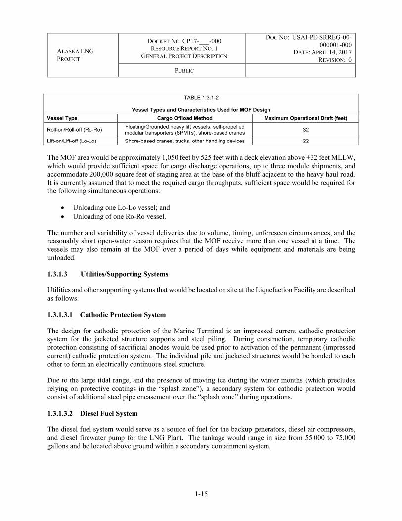
ALASKA LNG PROJECT
DOCKET NO. CP17-___-000 RESOURCE REPORT NO. 1
GENERAL PROJECT DESCRIPTION
DOC NO: USAI-PE-SRREG-00-000001-000
DATE: APRIL 14, 2017 REVISION: 0
PUBLIC
1-15
TABLE 1.3.1-2
Vessel Types and Characteristics Used for MOF Design Vessel Type Cargo Offload Method Maximum Operational Draft (feet)
Roll-on/Roll-off (Ro-Ro) Floating/Grounded heavy lift vessels, self-propelled modular transporters (SPMTs), shore-based cranes 32
Lift-on/Lift-off (Lo-Lo) Shore-based cranes, trucks, other handling devices 22
The MOF area would be approximately 1,050 feet by 525 feet with a deck elevation above +32 feet MLLW, which would provide sufficient space for cargo discharge operations, up to three module shipments, and accommodate 200,000 square feet of staging area at the base of the bluff adjacent to the heavy haul road. It is currently assumed that to meet the required cargo throughputs, sufficient space would be required for the following simultaneous operations:
Unloading one Lo-Lo vessel; and Unloading of one Ro-Ro vessel.
The number and variability of vessel deliveries due to volume, timing, unforeseen circumstances, and the reasonably short open-water season requires that the MOF receive more than one vessel at a time. The vessels may also remain at the MOF over a period of days while equipment and materials are being unloaded.
1.3.1.3 Utilities/Supporting Systems
Utilities and other supporting systems that would be located on site at the Liquefaction Facility are described as follows.
1.3.1.3.1 Cathodic Protection System
The design for cathodic protection of the Marine Terminal is an impressed current cathodic protection system for the jacketed structure supports and steel piling. During construction, temporary cathodic protection consisting of sacrificial anodes would be used prior to activation of the permanent (impressed current) cathodic protection system. The individual pile and jacketed structures would be bonded to each other to form an electrically continuous steel structure.
Due to the large tidal range, and the presence of moving ice during the winter months (which precludes relying on protective coatings in the “splash zone”), a secondary system for cathodic protection would consist of additional steel pipe encasement over the “splash zone” during operations.
1.3.1.3.2 Diesel Fuel System
The diesel fuel system would serve as a source of fuel for the backup generators, diesel air compressors, and diesel firewater pump for the LNG Plant. The tankage would range in size from 55,000 to 75,000 gallons and be located above ground within a secondary containment system.

ALASKA LNG PROJECT
DOCKET NO. CP17-___-000 RESOURCE REPORT NO. 1
GENERAL PROJECT DESCRIPTION
DOC NO: USAI-PE-SRREG-00-000001-000
DATE: APRIL 14, 2017 REVISION: 0
PUBLIC
1-16
1.3.1.3.3 Defrost Gas System
The defrost gas system would consist of heated natural gas. The defrost gas system would be used to warm and remove moisture or heavy hydrocarbons from the liquefaction trains during maintenance and startup activities.
1.3.1.3.4 Firewater System
A firewater tank would provide the primary firewater supply for the facility, and would have sufficient water to fight the largest credible anticipated fire for four hours. Makeup water for the firewater system would be pumped from one or more onsite freshwater wells. The tankage would hold approximately 1,200,000 gallons, which is two times the required National Fire Protection Association (NFPA) 59A amount (fire-fighting capacity for at least two hours). The lines along the trestle would be freeze-protected. Additional details concerning prevention of fire and fire safety equipment are provided in Resource Report Nos. 11 and 13.
1.3.1.3.5 Flare Systems
The Liquefaction Facility would be serviced by two flare systems, a wet/dry ground flare and a low-pressure flare. Any process streams containing a significant amount of water would be routed to a wet flare system in the event of upset conditions. Process streams that do not contain significant amounts of water would be routed to a dry flare. The flare system would be a multipoint ground flare located on the south side of the plant, consisting of a wet and dry ground flare with a common radiation fence. The ground flare’s surface area would be approximately 14 acres, including radiation fencing. The pilot light of the flare would be required to be active at all times for safe operations. Flare operation is only required during limited periods of startup, commissioning, shutdown, maintenance, or upset conditions. In either pilot or operating mode, flame from the flare would not be directly visible to the general public due to shielding by radiation fencing.
Most gas streams from LNG storage and loading systems and the BOG compression system would be routed to the low pressure (LP) flare. The LP flare would be approximately 200 feet high, located onshore adjacent to the Marine Terminal, and would support marine operations. It would be visible to the general public during normal operations and upset conditions. The independent LP flare system, separate from the wet/dry ground flare, is required for these systems due to low backpressure requirements.
A thermal oxidizer would incinerate vented hydrocarbon vapors from condensate storage and loading. Operational vapors from the condensate storage tank resulting from the tank out breathing (i.e., filling causing displacement of gas out of the tank) would be sent to the thermal oxidizer, which would be located in the condensate storage area. In the event of an upset of the thermal oxidizer, gases would be sent to the LP flare via blower assist.
1.3.1.3.6 Fuel Gas System
The Fuel Gas System for the LNG Plant would be a common system that supplies the entire Liquefaction Facility, for both continuous use and applicable intermittent fuel gas use. The Fuel Gas System would supply both high pressure (HP) and LP fuel gas.

ALASKA LNG PROJECT
DOCKET NO. CP17-___-000 RESOURCE REPORT NO. 1
GENERAL PROJECT DESCRIPTION
DOC NO: USAI-PE-SRREG-00-000001-000
DATE: APRIL 14, 2017 REVISION: 0
PUBLIC
1-17
BOG would be the primary source of fuel gas. Makeup fuel gas upstream of the dehydration system would be added to the Fuel Gas System as needed to handle normal fluctuations in fuel gas consumption or in case of loss of BOG.
Makeup fuel gas for startup would come from downstream of the inlet gas filter. The refrigeration gas turbines would consume about 80 percent of the total fuel gas consumed by the Liquefaction Facility. The expected fuel consumption by the refrigeration and the power generation gas turbines would range from 5.1 to 5.4 billion BTU per hour (BBtu/h) and 0.8 to 1.2 BBtu/h, respectively, during normal operations.
1.3.1.3.7 Nitrogen System
Nitrogen gas would be produced on site using a nitrogen system delivering high purity (99.9 percent), low purity (98.7 percent) nitrogen, and flash gas (98.7 percent). The system would supply nitrogen gas for the following purposes:
Mixed refrigerant makeup (high purity); Inert purging; Compressor seals; and Blanketing of equipment (i.e., nitrogen is used to maintain a protective layer of gas).
1.3.1.3.8 Plant/Instrument Air System
An air system for the Liquefaction Facility would supply compressed dry air for instruments, purging, pneumatic tools, and other utility needs. Major components of the plant and instrument air system include motor-driven main air compressors; a low sulfur, diesel-fueled back-up compressor; air receivers; and air dryer.
1.3.1.3.9 Power Supply
The local utility Homer Electric Association (HEA) would serve both temporary construction power and essential power for operations at 24.9 kilovolt (kV) three-phase and use 24.9 kV primary metering. The Project would be responsible for power beyond the 24.9 kV primary metering demarcation. HEA’s current system capabilities to support construction and essential power are 20 megavolt amperes (MVA) (peak maximum) and 8 MVA (peak maximum, respectively).
Onsite power for the Liquefaction Facility would be derived from multiple gas turbine generators in an “N”+1 configuration, such that any “N” (or number of) generators would be able to provide the full power requirement for the LNG Plant and Marine Terminal (plus one in reserve). During normal operations, the power generation facility would supply 124 megawatts (MW). The plant is not designed to export power to the grid.
A sufficient number of diesel generators would be connected to form a centralized essential power system, powering only the essential systems to maintain plant safety during power failure. An automatic transfer scheme would be provided to switch essential loads to the diesel generators upon failure of the normal power system or alternatively to local power if it turns out to be feasible to connect to the local grid for essential and black-start power.

ALASKA LNG PROJECT
DOCKET NO. CP17-___-000 RESOURCE REPORT NO. 1
GENERAL PROJECT DESCRIPTION
DOC NO: USAI-PE-SRREG-00-000001-000
DATE: APRIL 14, 2017 REVISION: 0
PUBLIC
1-18
1.3.1.3.10 Waste Heat Recovery System
Waste heat from the power generation facility would be used to generate steam for the LNG Plant. The main uses of the steam would be:
Generating electricity via steam turbine; Inlet natural gas heater; Distillation column reboilers; Fuel gas heating; and Preheating fresh well water.
1.3.1.3.11 Water Supply System
Freshwater would be supplied by new groundwater well(s) located near the liquefaction trains. For operations, the water supply system would consist of:
Lift pumps;
Intake screens;
Two freshwater storage tanks with a total required storage of over 1 million gallons’ net-working volume;
A supply line to the freshwater tanks;
A supply line to the firewater tank; and
Freshwater tank feed lines.
1.3.1.3.12 Fresh Water Treatment System
A water treatment system would be included in the facility. A cartridge filter in combination with reverse osmosis and electrodeionization would be used to produce high quality demineralized water for high pressure steam generation. Freshwater would be treated through several processes to meet the various water service needs in the plant. These consist of:
Demineralization – this is necessary to produce water of the highest quality required for the steam system, turbine water washing, etc.;
Potable – this is required to produce water for domestic use (i.e., drinking water, safety showers, kitchen facilities, etc.; and
Utility – this is required for general purpose needs such as pump seal cooling and utility stations located throughout the plant.

ALASKA LNG PROJECT
DOCKET NO. CP17-___-000 RESOURCE REPORT NO. 1
GENERAL PROJECT DESCRIPTION
DOC NO: USAI-PE-SRREG-00-000001-000
DATE: APRIL 14, 2017 REVISION: 0
PUBLIC
1-19
Wastewater and wastewater treatments are discussed in Section 1.3.8.
1.3.1.4 Associated Infrastructure
To operate the Liquefaction Facility, additional facilities would be built and maintained on site. A description of these additional facilities is provided as follows.
1.3.1.4.1 Condensate Storage and Truck Loading Facility
Approximately 1,000 barrels per day of condensate removed from the natural gas stream by the liquefaction process would be distributed by truck (approximately five to six trucks per day) or potentially piped to a customer in the local vicinity of the LNG Plant.
The condensate product would first be stored in a condensate storage tank. The truck loading system would include the equipment necessary for the safe and reliable handling and loading of condensate (e.g., pumps or lease automatic custody transfer (LACT) unit, truck loading facility, vapor handling, and disposal). Current design status of the condensate storage and loading system are depicted in the following process flow diagrams included in Resource Report 13, Attachment U: AKLNG-4030-PPP-PFD-DOC-00010 (USAL-CB-PDPFD-70-000634-001) and piping & instrumentation diagrams AKLNG-4030-PID-DWG-DOC-00141 through AKLNG-4030-PID-DWG-DOC-00145, AKLNG-4030-PPP-DWG-DOC-00025, and AKLNG-4030-PID-DWG-DOC-00146 (USAL-CB-PDPID-70-000634-701 through 707). The details of the LACT unit and truck loading facility will be developed prior to construction; but these facilities will be industry typical as appropriate for the local Alaska environment. Additional information regarding product volume, disposition, and means of transport will also be provided prior to construction.
1.3.1.4.2 Refrigerant Production and Storage
In general, refrigerants required for the liquefaction process would be available on site. Propane would be imported for the initial fill for one train and then produced on site for operational use and augmented from the natural gas supply as required by operations. Train 1 would start up utilizing only propane. Ethane would also be produced and stored on site once Train 1 is in operation. The fractionation process would extract propane and ethane from the product stream to be stored as refrigerant on site as required to support refrigerant makeup. The remaining propane and ethane would be reinjected into the LNG product stream. Ethane would be stored in two bullet tanks with a total of approximately 120,000 gallons. Propane would be stored in four tanks with a total capacity of approximately 295,000 gallons.
1.3.1.4.3 Catalysts and Chemicals
The LNG Plant would use catalysts for the following general applications:
Activated Carbon as pellets for mercury removal – approximately 1,900 cubic feet;
Molecular Sieve as pellets for water removal – approximately 2,000 cubic feet;
Activated Alumina as pellets for water removal – approximately 200 cubic feet; and

ALASKA LNG PROJECT
DOCKET NO. CP17-___-000 RESOURCE REPORT NO. 1
GENERAL PROJECT DESCRIPTION
DOC NO: USAI-PE-SRREG-00-000001-000
DATE: APRIL 14, 2017 REVISION: 0
PUBLIC
1-20
Carbon monoxide (CO) catalyst as pellets to reduce CO content of gas turbine exhaust to acceptable levels (vendor to advise quantity).
The catalysts would be placed into the process trains prior to LNG Plant startup. Their effectiveness would be monitored over time to determine if, and when, they need to be replaced during a planned shut-down period. In general, each of the above catalysts is expected to have a minimum four-year life.
Although the LNG Plant would not use any chemicals as part of the process, the following chemicals would be used in small quantities to help treat fresh water, boiler feed water, and various wastewater streams:
Amine for boiler feed water treatment; Oxygen Scavenger for boiler feed water treatment; Scale Inhibitor for boiler feed water treatment; Anti-scale Inhibitor for boiler feed water treatment; Sodium Bisulfite in the Reverse Osmosis unit; Polymer in the clarification package; Oxidizer in the clarification package; Coagulant in the clarification package; Sodium Hypochlorite for treating potable water, fresh water and sanitary effluent; Activated carbon for potable water and steam condensate treatment; Caustic Soda for pH control in the neutralization package; Acid pH control in the neutralization package; Coagulant in the Dissolved Gas Filtration unit; and Desiccant for the Instrument Air Dryer package.
Appropriate quantities of these chemicals based on daily consumption and normal resupply cycles would be stored on site in a chemical storage building that provides segregation of materials and is equipped with fire and gas detection, firewater, spill containment, and other ancillary protective features as required by code.
In addition, about 3,646,000 gallons of diesel would be stored at the site for potential use in the black start16 of the facility and for emergency diesel generators necessary to generate power whenever there is insufficient feed gas to generate power.
1.3.1.4.4 Lighting
The Liquefaction Facility would need lighting for plant operations, perimeter security, access, and emergencies. During operations, lights would be used to illuminate work spaces and to ensure the safety and security of Liquefaction Facility structures and operations, including the Marine Terminal. Liquefaction Facility lighting would meet regulatory requirements, codes, and standards. The lighting
16 Start-up following a total or partial shut-down of supplied power

ALASKA LNG PROJECT
DOCKET NO. CP17-___-000 RESOURCE REPORT NO. 1
GENERAL PROJECT DESCRIPTION
DOC NO: USAI-PE-SRREG-00-000001-000
DATE: APRIL 14, 2017 REVISION: 0
PUBLIC
1-21
design would illuminate only places where needed and avoid impacts to neighboring communities and wildlife.
Area lighting would be provided at the PLF, including task lighting on the mooring dolphins and the breasting dolphins.
Additional details on lighting are provided in the Lighting Plan in Appendix O of Resource Report No. 8.
1.3.1.4.5 Communications Facilities
Communications systems would include:
Fiber optic and structured cabling; A telephone system; A radio system; Safety/security systems; A meteorological system; Marine communications; and A permanent communications tower (approximately 150 feet high).
The telecommunication tower, as well as the BOG Flare stack, would be lit in accordance with Federal Aviation Administration (FAA) requirements once the required FAA determination is rendered.
1.3.1.4.6 Operations Buildings and Control Room
The central control room would be located as close as possible to the plant process trains but outside of any defined hazard zones for its location. The central control room would be part of a consolidated building complex that would also include the following plant services:
Administrative area with offices and conference space for Project workers;
Maintenance/shop area where equipment would be repaired, tested, inspected, etc., with offices;
Emergency response area for medical facilities and response equipment;
Warehouse with separate areas to receive, inspect, and store goods received. It would also include areas for climate control storage, dispensing material for daily operations, and office facilities for warehouse personnel. Rotating equipment parts requiring unique storage needs would also be contained in the warehouse; and,
Laboratory area containing equipment capable of analyzing refrigerants, process gas, fuel gas, LNG, and performing liquid hydrocarbon and water analysis.
Other operations structures located in the liquefaction facilities site would include:

ALASKA LNG PROJECT
DOCKET NO. CP17-___-000 RESOURCE REPORT NO. 1
GENERAL PROJECT DESCRIPTION
DOC NO: USAI-PE-SRREG-00-000001-000
DATE: APRIL 14, 2017 REVISION: 0
PUBLIC
1-22
A staff assembly building to support meetings, training, and/or maintenance activities (e.g., facility startups and turnarounds);
Onsite security buildings for main plant entrances, process area entrance (may be combined with the consolidated building complex), and for marine access control;
A truck loading station (that may be combined with a substation or weather shelter) for support of this operation; and
Weather/break shelters statically located around the plant.
1.3.1.5 Temporary Facilities Associated with the Construction of the Liquefaction Facility
In addition to the permanent facilities identified previously, the design and preliminary construction plan anticipates that the Liquefaction Facility may require the following facilities during construction:
Temporary construction camp and other infrastructure to support the construction workforce;
Temporary infrastructure to support construction (e.g., concrete batch plants, construction equipment storage, site operations center, contractor and owner offices, warehousing, construction fuel storage tanks, construction water source and temporary potable water plant, temporary domestic wastewater treatment plant, construction power, telecommunications tower and radio base station, and laydown areas);
Material sites (if required);
Disposal areas for construction debris and for blast rock (as necessary);
Prior to completion of the Liquefaction Facility MOF, a Pioneer MOF would be required to handle offloading of aggregate and bulk construction materials and equipment needed for the Marine Terminal and/or the LNG Plant, as well as a potential support facility for Cook Inlet pipeline construction; and
MOF to facilitate handling of prefabricated modules and other cargo transported from vessels and marine heavy lift vessels (described in Section 1.3.1.2).
1.3.1.5.1 Construction Camp
The Liquefaction Facility construction camp and associated camp facilities would be located on approximately 81 acres of land adjacent or in close proximity to the Liquefaction Facility. The camp would accommodate the workforce and would include dormitories, a cafeteria, recreation rooms, and other amenities. The camp would have a design life of approximately six years, and its installation would be one of the first onsite activities.
Prior to camp construction, personnel would be housed in local accommodations. The maximum number of construction personnel to be housed in local accommodations at any time would likely be fewer than
ALASKA LNG PROJECT
DOCKET NO. CP17-___-000 RESOURCE REPORT NO. 1
GENERAL PROJECT DESCRIPTION
DOC NO: USAI-PE-SRREG-00-000001-000
DATE: APRIL 14, 2017 REVISION: 0
PUBLIC
1-23
300. The workforce size is predicted to peak at 4,400 to 5,000 persons and the camp design would be modular with the ability to add additional accommodations greater than 5,000, but also be able to function efficiently with a reduced number of camp residents. The construction camp would be located contiguous to the Liquefaction Facility site to prevent the need for offsite traffic and road crossings during shift changes. This would minimize impacts to local traffic and reduces the risk of potential traffic accidents for workers and residents. Workers would be bused within the site. Details on lighting at the construction camps are provided in the Lighting Plan in Appendix O of Resource Report No. 8.
1.3.1.5.2 Construction Fuel Storage Tanks
Each construction contractor would either contract with suppliers to acquire the fuel necessary for construction or would build and maintain a fuel depot to be used during the construction period. The fuel depot would consist of fuel dispensing equipment, storage tanks, secondary containment systems, and safety/cleanup resources required to address any spills during construction. Fuel types would be dictated by the of the types and numbers of equipment each contractor brings to the Project site during construction.
The onshore construction fuel storage tanks would consist of five 10,000-gallon tanks. The five tanks would include three diesels and two gasoline tanks. The tanks would be filled by barge or tanker truck from a local supplier. The tanks would be aboveground, horizontal, double-wall, steel storage tanks in conformance with the Underwriters Laboratories' UL-142 specifications. Tanks would be arranged to allow access alongside all tanks allowing 20 vehicles to fill at once. The fuel depot would also allow for refueling heavy construction equipment.
The fuel area would be designed and operated in compliance with Alaska Department of Environmental Conservation (ADEC) and U.S. Environmental Protection Agency (EPA) requirements. The Project-specific Spill Prevention, Containment, and Control (SPCC) Plan (Resource Report No. 2, Appendix M) would address the following:
Double-walled tanks; Secondary containment area; Providing spill cleanup supplies; Trained and dedicated response personnel to respond to any spills; and Spill reporting procedures.
1.3.1.5.3 Construction Water Source and Temporary Potable Water Plant
Water would be sourced from water wells, with the exception that tank hydrostatic test water would come from Cook Inlet. Onsite water demand would peak at approximately 300,000 gallons per day or 250 gallons per minute for construction and potable water. Potable water demand is estimated to be approximately 50–75 gallons of water per person per day. The following construction activities are the majority contributors to site peak water demand:
Hydrostatic testing each of the 240,000-cubic-meter tanks would require approximately 42,000,000 gallons of Cook Inlet seawater over a 14–21-day period between July and December, with an average fill rate of about 1,400–2,000 gallons per minute. The hydrostatic test water would be treated and managed in accordance with applicable permits, and be returned to Cook Inlet (See

ALASKA LNG PROJECT
DOCKET NO. CP17-___-000 RESOURCE REPORT NO. 1
GENERAL PROJECT DESCRIPTION
DOC NO: USAI-PE-SRREG-00-000001-000
DATE: APRIL 14, 2017 REVISION: 0
PUBLIC
1-24
the Water Use Plan in Resource Report No. 2). Freshwater would be used to rinse the tanks. No biocides would be used, and hydrostatic testing would likely occur in the warmer months;
The concrete batch plants would require dedicated water storage of approximately 50,000 gallons per day of freshwater to allow continuous concrete placement;
Approximately 10,000 gallons per day of freshwater would be required for daily dust suppression during dry summer months (soil compaction requires approximately 20 gallons per cubic yard);
Hydrostatic testing of the LNG Plant piping would be anticipated to require approximately 50,000 gallons of freshwater; and
During commissioning of the LNG Plant, water would be required for flushing and filling the water systems for the first time. Preliminary estimates are that approximately 2,260,000 gallons of freshwater would be required for flushing (i.e., moving the fluid through the system at the same speed at which it would go through it under normal operating conditions) of piping in the water systems (firewater makeup, potable water, demineralized water, and service water). The first filling of the freshwater system would require approximately 510,000 gallons of water.
Groundwater wells would be located near the site, providing approximately 250 gallons per minute with a combined output of 1.4 million gallons per day. These wells would be used for construction and are not currently planned to support operations (see previous Water Supply System section). Groundwater wells would also be used for the temporary potable water plant. This water would be distributed through the construction camp, office complex, mechanic shop, and induction building. One of the groundwater wells would be used as a spare and for dust control.
Existing water wells on the property can be used during the early stages of site construction as additional water supply. However, these wells are not sufficient to supply the anticipated construction water demand.
For construction, the total storage required would be 1,380,000 gallons’ net working volume. The system would consist of:
Two freshwater tanks (690,000 gallons each); Intake screens at pumps suction; and Six-inch freshwater tank feed lines.
During initial site preparation, bladder tanks and temporary ponds may be used for water storage.
Two temporary water treatment plants would be located on site during construction—one adjacent to the construction camp and the second located adjacent to the onsite concrete batch plant. A third temporary water treatment plant is being considered to support hydrostatic testing and would be located near the liquefaction trains. The plants would source water from the new construction wells, potentially supplemented by the existing onsite wells, if they are not removed during site clearing and grading.

ALASKA LNG PROJECT
DOCKET NO. CP17-___-000 RESOURCE REPORT NO. 1
GENERAL PROJECT DESCRIPTION
DOC NO: USAI-PE-SRREG-00-000001-000
DATE: APRIL 14, 2017 REVISION: 0
PUBLIC
1-25
1.3.1.5.4 Construction Power
The initial power demand range during construction would be approximately 20 to 25 MW. Actual power requirements would vary as the construction activity fluctuates between the summer and winter months. Portable generators would be on site for both backup and active work (e.g., welding). The generators would have drip pans and containment. HEA would supply power during construction.
1.3.1.5.5 Telecommunications Tower and Radio Base Station
Temporary communications would require installation of one or more telecommunications towers (estimated to be approximately 150 feet high) and radio base stations, which would also include the associated fiber optics cabling. The Project’s representatives would consult with the U.S. Fish and Wildlife Service (USFWS) regarding designing the tower to minimize impacts on birds.
1.3.1.5.6 Other Liquefaction Facility Temporary Infrastructure
The preliminary design includes temporary facilities to support construction of the Liquefaction Facility. These facilities would be found within the footprint of the site. The preliminary assessment of the infrastructure needs would include:
A main gate security office and main gate reception buildings;
An induction building composed of two offices and two classrooms for personnel training and inductions;
A safety office and clinic, including medical reception area, waiting room, and clinic rooms;
An office complex with offices located to avoid relocation during commissioning and startup. Small satellite offices would be located away from the office complex and close to the work front to streamline daily site construction activities. Satellite offices would include the LNG tank subcontractor office, trestle office, and civil office;
Two temporary offices to support heavy haul road construction. As the earthwork nears completion, two temporary offices would be established near the top of the haul road to enable a direct line of sight to the job site, heavy haul road, MOF, and Cook Inlet;
A temporary vehicle parking lot near the construction gate and office complex for personnel vehicles. The parking lot would be compacted road base surface;
A temporary bus parking lot for approximately 66 buses (45-person capacity per bus) used to transport workers between the camp and the work site. Eleven acres have been allocated on the site for bus parking near the camp to decrease travel time for buses to travel from the camp and the parking lot. This would decrease both onsite and offsite traffic congestion. The parking lot would be compacted road base surface;
Stockpiles, including:

ALASKA LNG PROJECT
DOCKET NO. CP17-___-000 RESOURCE REPORT NO. 1
GENERAL PROJECT DESCRIPTION
DOC NO: USAI-PE-SRREG-00-000001-000
DATE: APRIL 14, 2017 REVISION: 0
PUBLIC
1-26
○ Topsoil stockpiles, located away from onsite pedestrian and daily traffic routes;
○ Aggregate and sand stockpiles located adjacent to the batch plant; and
○ Snow, which would be removed from work areas, roads, parking lots, laydown, and walkways with loaders and graders, and stockpiled in the designated area.
Temporary onsite shops (i.e., pipe fabrication shop, iron workers shop, electrical shop, instrument calibration shop, mechanic shop, and carpentry shop) for repair, preassembly, or fabrication of material before the final installation location is ready;
Five warehouses. Two unheated warehouses would be 10,000 square feet each and two heated warehouses would be 10,000 square feet each. These warehouses would be adjacent to 32 acres of laydown space. Each warehouse would have a concrete slab, office, shelving, and access bay for truck unloading and loading. There would also be a warehouse adjacent to the civil office to store material such as forms, rebar, sheeting, blankets, lumber, and heaters;
Chemical storage (e.g., paints, thinners, specialty cleaning materials), set on a secure 1-acre plot, with fencing, secondary containment, and warning signage;
Laydown areas strategically located on site taking into account site topography, efficient traffic routes to work fronts, and efficient delivery routes from the main gate. A typical laydown area would be designed with a center two-lane road and laydown areas on either side of the road. Laydown areas would be designed with minimal cut and fill earthworks and have a finished surface. Where needed, a compacted layer of sand and granular material would be placed on the surface of the laydown areas. The layer would be sloped to allow surface water to run off without ponding or pooling.
○ Permanent equipment and modules such as vessels, cranes, and pumps would be stored in the permanent equipment and module laydown area if the installation site is not immediately available upon delivery. The laydown would be located adjacent to the heavy haul route and close to the LNG trains;
○ The construction equipment laydown area would be designated for onsite equipment parking;
○ Permanent material such as bulk pipe, pipe supports, embeds, electrical bulks, insulatory materials, and structural steel would be stored in the permanent material laydown area;
○ A dedicated laydown area would be located adjacent to the LNG tanks;
○ Temporary material used for construction would be segregated from permanent material in a dedicated laydown area;
○ A laydown area would be designated to store precast concrete elements (e.g., small foundations, culverts, LNG trenches); and

ALASKA LNG PROJECT
DOCKET NO. CP17-___-000 RESOURCE REPORT NO. 1
GENERAL PROJECT DESCRIPTION
DOC NO: USAI-PE-SRREG-00-000001-000
DATE: APRIL 14, 2017 REVISION: 0
PUBLIC
1-27
○ Scaffold materials (e.g., clamps, poles) would be organized by type on pallets or in bins and racks.
A wash facility, to clean vehicles and equipment, consisting of a drive-through bay with a pressure washer and drainage. The wash-down pad wastewater would be contained in a wash-down pad sump, which would be sized to hold 2,000 gallons. This would be a closed loop system and water would be recycled into the wash-down area;
A waste segregation area to categorize and temporarily store construction waste on site before reuse, recycling, or transport offsite for disposal;
Two onsite concrete batch plants are planned, each capable of producing 120 cubic yards per hour. A backup facility within 25 miles of the site would supplement the onsite batch plants during the pioneer phase. The batch plants would supply and deliver concrete to mixer trucks and pump trucks. Nine to 27 concrete mixer trucks each with minimum capacity of 9 cubic yards would be maintained. The batch plants would be located adjacent to aggregate and sand stockpiles. Wastewater for the batch plants would be on a closed loop system. Materials would be delivered to the batch plants via truck;
A concrete quality testing laboratory capable of testing raw and finished material to demonstrate conformance with American Concrete Institute and National Ready-Mixed Concrete Association Standards;
Heated, fabric lunch tents with concrete slab floors;
A tool room with a design similar to the unheated warehouses;
A self-contained, indoor restroom facility. The building would be trailer-mounted and have separate female and male facilities with multiple stalls and a 1,000-gallon waste tank. During the summer months, the restroom facility would be supplemented with portable restrooms and hand-wash stations; and
A secure, restricted access area to store radioactive materials used in non-destructive testing of facility piping, located within the pipe fabrication shop area separate from fabrication activities and away from vehicular or pedestrian traffic. The material would be stored in a walled and roofed structure for protection against storm and rain. The storage area would be set on a secure plot, with fencing and warning signage.
Heavy Haul Road
The temporary heavy haul road would be used to transport modules, equipment, and bulk materials from the MOF up the bluff to the LNG Plant site. The road would be constructed of compacted road bed materials from local material sites or from on site. The bluff is approximately 100 feet high and forms the western border of the proposed LNG Plant site. Table 1.3.1-3 provides the temporary heavy haul road design characteristics.

ALASKA LNG PROJECT
DOCKET NO. CP17-___-000 RESOURCE REPORT NO. 1
GENERAL PROJECT DESCRIPTION
DOC NO: USAI-PE-SRREG-00-000001-000
DATE: APRIL 14, 2017 REVISION: 0
PUBLIC
1-28
TABLE 1.3.1-3
Preliminary Minimum Construction and Temporary Heavy Haul Road Design Characteristics Design Characteristic Heavy Haul Road Inside Turning Radius 45 feet Lane Width 75 feet Number of Lanes 2 Shoulder Width 0 feet V-Drain Width 4 feet
Marine Terminal Temporary Infrastructure
The temporary facilities at the Marine Terminal to support construction include:
A road constructed along the alignment of the haul road from the MOF, contained within the haul road;
The MOF construction staging area located within the footprint of the MOF and containing an area of fill to allow construction to proceed; and
Shoreline stabilization to prevent erosion of the shoreline undermining the MOF and beach access road.
Initially a laydown area would be placed at the top of the bluff. This area and associated facilities would be used during the construction of the MOF and then removed at the completion of the MOF construction.
Pioneer MOF
Existing facilities in the area would be used for a Pioneer MOF. The Pioneer MOF would support construction prior to completion of the MOF and during peak construction periods. The Pioneer MOF would make use of an existing dock facility along with laydown areas and storage and office space.
1.3.2 Interdependent Project Facilities
In addition to the Liquefaction Facility, Project facilities would include the Mainline, GTP, PBTL, and PTTL to move and process natural gas from the North Slope to the Liquefaction Facility. Preliminary pipeline route maps in Appendix A have assigned mileposts (MPs) on the pipeline according to convention to reflect natural gas flow (i.e., from north to south in the case of the Mainline and from east to west in the case of the PTTL).
1.3.2.1 Mainline
The Mainline would be a 42-inch-diameter natural gas pipeline, approximately 807 miles in length, extending from the GTP in the PBU to the Liquefaction Facility on the shore of Cook Inlet near Nikiski, including an offshore pipeline section crossing Cook Inlet. The pipeline would be a buried pipeline with

ALASKA LNG PROJECT
DOCKET NO. CP17-___-000 RESOURCE REPORT NO. 1
GENERAL PROJECT DESCRIPTION
DOC NO: USAI-PE-SRREG-00-000001-000
DATE: APRIL 14, 2017 REVISION: 0
PUBLIC
1-29
the exception of two planned aerial water crossings, aboveground crossings of active faults, and the offshore pipeline. As presented in Table 1.3.2-1, the Mainline would originate in the North Slope Borough; traverse the Yukon-Koyukuk Census Area, the Fairbanks North Star Borough, the Denali Borough, the Matanuska-Susitna Borough, and the Kenai Peninsula Borough; and terminate at the Liquefaction Facility. The Mainline is designed for a maximum allowable operating pressure (MAOP) of 2,075 psig and an average stream day rate of 3.1 BSCF/D, and a 3.3 BSCF/D peak capacity.17
The proposed Mainline route begins at the GTP in the PBU and would generally follow the Dalton Highway (Alaska Highway 11) and Trans-Alaska Pipeline System (TAPS) southward from the Prudhoe Bay area to Livengood. From there, the route generally parallels the east side of the Tolovana River south, crossing west of Fairbanks near Minto Lakes, to the Tanana River and follows the Parks Highway (Alaska Highway 3) southward to a point just south of Trapper Creek. From this point, the Mainline route would continue to the south and southwest following along the west side of the Susitna River to the Deshka River. From the Deshka River, the Mainline route runs southwest to the north shore of Cook Inlet northeast of Viapan Lake, which is between the communities of Beluga and Tyonek. The offshore portion of the Mainline route crosses Cook Inlet to the Kenai Peninsula at Boulder Point. From the south shore of Cook Inlet at Boulder Point, the Mainline route continues south and west to the termination point at the proposed Liquefaction Facility.
Table 1.3.2-1 provides a summary of the proposed Mainline route, including the pipeline diameter and approximate lengths located within each borough and census area crossed. The location of the Mainline facilities are depicted on aerial imagery and USGS maps provided in Appendix A.
TABLE 1.3.2-1
Mainline Route Summary for a 42-inch Pipeline Segment or Facility Name Boroughs or Census Areas
Approximate Length (miles)
Mainline
North Slope Borough 182 Yukon-Koyukuk Census Areas 304 Fairbanks North Star Borough 2 Denali Borough 87 Matanuska-Susitna Borough 180 Kenai Peninsula Borough 51
Total 806.6
Table 1.3.2-2 summarizes collocation of the Mainline route that is within 500 feet of highways, major roads, TAPS, other pipeline ROWs, utilities, and railroads. Further discussion on Alaska LNG’s definition of collocation is provided in Resource Report No. 10, Section 10.4.2.2. Mainline collocation opportunities by MP are provided in Appendix N. Approximately 34 percent of the Mainline route is collocated within 500 feet of an existing ROW.
17 Average stream day rate denotes the weighted 12-month average of monthly stream day rate values. Stream day rate represents the physical capacity of the facility at a particular ambient condition and does not account for planned or unplanned downtime (assume 100-percent uptime).

ALASKA LNG PROJECT
DOCKET NO. CP17-___-000 RESOURCE REPORT NO. 1
GENERAL PROJECT DESCRIPTION
DOC NO: USAI-PE-SRREG-00-000001-000
DATE: APRIL 14, 2017 REVISION: 0
PUBLIC
1-30
TABLE 1.3.2-2
Collocated ROWs with the Mainline (within 500 feet) Borough/Census Area Category Length (Miles) Length (Feet) North Slope Borough
Trans-Alaska Pipeline System (TAPS) 24.39 128,768
Other Pipelinesa 34.83 183,904
Highways or Major Roadsb 59.97 316,630
Utilities 108.65 573,692 Railroads - -
Yukon-Koyukuk Census Area TAPS 64.14 338,653
Other Pipelinesa - -
Highways or Major Roadsb 94.13 496,985
Utilities 106.42 561,898 Railroads 0.83 4,405
Denali Borough TAPS - -
Other Pipelinesa 0.09 453
Highways or Major Roadsb 13.25 69,984
Utilities 46.21 243,983 Railroads 1.00 5,283
Matanuska-Susitna Borough TAPS - -
Other Pipelinesa 2.31 12,206
Highways or Major Roadsb 26.76 141,289
Utilities 29.76 157,157 Railroads 2.30 12,123
Kenai Peninsula Boroughc TAPS - -
Other Pipelinesa 3.37 17,810
Highways or Major Roadsb 1.58 8,342
Utilities 0.02 130 Railroads - -
Total Collocation Opportunities 289.58 1,528,971 ____________________ a Other Pipelines - any pipeline other than the Trans-Alaska Pipeline System. b Highways or Major Roads - includes public roads only. c Kenai Peninsula Borough - includes offshore portions of the Mainline.
Although the Mainline route is generally parallel with either TAPS or highway ROW, there are locations where collocation is not practical due to the following considerations:

ALASKA LNG PROJECT
DOCKET NO. CP17-___-000 RESOURCE REPORT NO. 1
GENERAL PROJECT DESCRIPTION
DOC NO: USAI-PE-SRREG-00-000001-000
DATE: APRIL 14, 2017 REVISION: 0
PUBLIC
1-31
Minimization of potential impacts to environmental resources (e.g., waterbody crossing locations, cultural sites, State and Federal Conservation Lands, length of route);
Minimization of impacts to existing infrastructure (e.g., pump stations, at pinch points between TAPS and the highway, subdivisions, occupied buildings, private lands) (Note: the Project representatives would be required to acquire a letter of non-objection from TAPS and other existing ROWs to cross or encroach on their ROWs). The general approach for construction in proximity to TAPS and crossing TAPS has been coordinated with the TAPS operator, Alyeska Pipeline Service Company (APSC), with site-specific approaches reported (see Resource Report 11, Section 11.7.2.7.4 for information on the TAPS Impact Study);
Minimization of impacts from geohazards (e.g., cross slopes, at pinch points with infrastructure and mountains, steep longitudinal slopes, watercourses, floodplains, seismic fault lines); and
Restriction in placement options due to the presence of the existing infrastructure.
Additional information that defines constraints to overlap with or abut existing infrastructure is provided in Section 10.4.2.1 (Major Route Alternatives) of Resource Report No. 10.
1.3.2.1.1 System Design
The hydraulics design of the Mainline defines the delivery quantities, and liquid dropout limits, if any, and the operating temperature limits to minimize impact on areas that are vulnerable to frost heave or thaw settlement. The preliminary design parameters of the Project are provided in Table 1.3.2-3.
TABLE 1.3.2-3
Gas Quality Limits
Parameter Limit or Operating Range Basis
Pipeline pressure 2,075 psig maximum at the GTP 1,050–2,075 psig at the LNG Plant
GTP and LNG Plant design
Pipeline temperature 30 °F to 32 °F at the GTP 32 °F to 80 °F at the LNG Plant
Buried pipeline. Temperature chosen to minimize impact to natural permafrost.
Ambient temperature Minimum recorded: -70 °F Minimum daily average: -50 °F
Data collected by National Oceanic and Atmospheric Administration (NOAA) and Western Region Climate Center
H2S 4 ppmv maximum GTP and LNG Plant design
Water content 0.2 lbs./mmscf Chosen to minimize Mainline corrosion and hydrate formation
CO2 < 50 ppmv GTP and LNG Plant design
_________________ Notes:
lbs. = pounds MMSCF = million standard cubic feet ppmv = parts per million by volume psig = pounds per square inch gauge
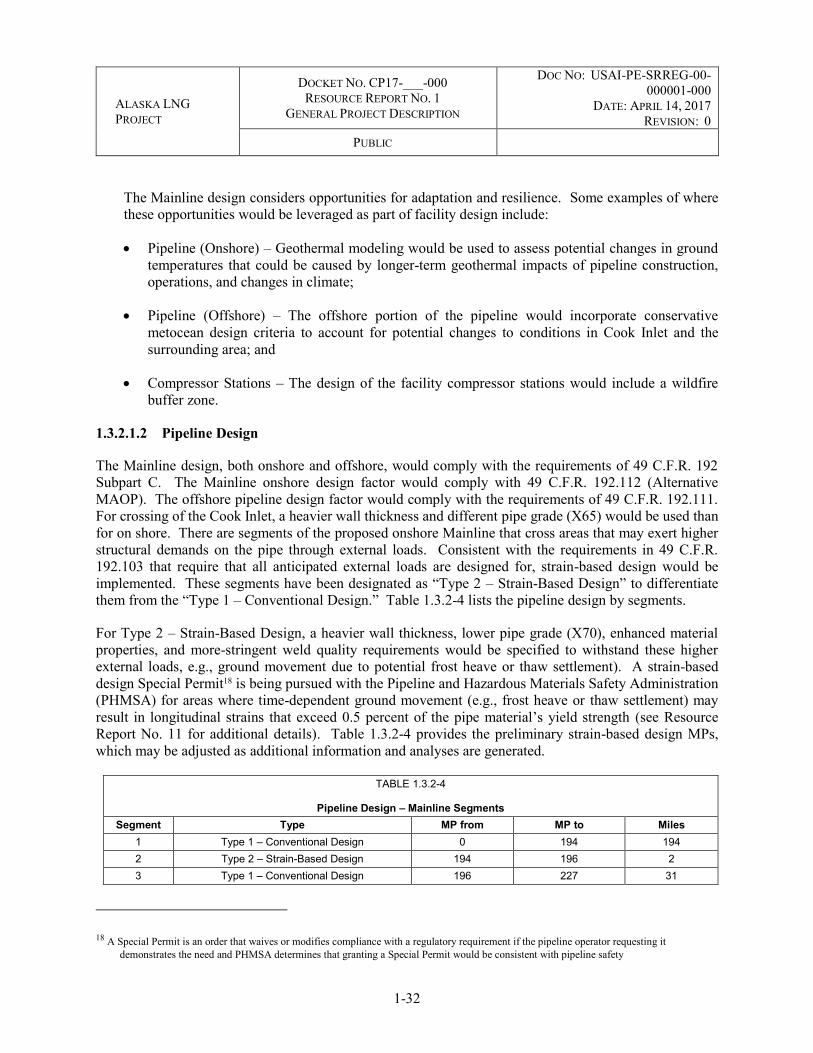
ALASKA LNG PROJECT
DOCKET NO. CP17-___-000 RESOURCE REPORT NO. 1
GENERAL PROJECT DESCRIPTION
DOC NO: USAI-PE-SRREG-00-000001-000
DATE: APRIL 14, 2017 REVISION: 0
PUBLIC
1-32
The Mainline design considers opportunities for adaptation and resilience. Some examples of where these opportunities would be leveraged as part of facility design include:
Pipeline (Onshore) – Geothermal modeling would be used to assess potential changes in ground temperatures that could be caused by longer-term geothermal impacts of pipeline construction, operations, and changes in climate;
Pipeline (Offshore) – The offshore portion of the pipeline would incorporate conservative metocean design criteria to account for potential changes to conditions in Cook Inlet and the surrounding area; and
Compressor Stations – The design of the facility compressor stations would include a wildfire buffer zone.
1.3.2.1.2 Pipeline Design
The Mainline design, both onshore and offshore, would comply with the requirements of 49 C.F.R. 192 Subpart C. The Mainline onshore design factor would comply with 49 C.F.R. 192.112 (Alternative MAOP). The offshore pipeline design factor would comply with the requirements of 49 C.F.R. 192.111. For crossing of the Cook Inlet, a heavier wall thickness and different pipe grade (X65) would be used than for on shore. There are segments of the proposed onshore Mainline that cross areas that may exert higher structural demands on the pipe through external loads. Consistent with the requirements in 49 C.F.R. 192.103 that require that all anticipated external loads are designed for, strain-based design would be implemented. These segments have been designated as “Type 2 – Strain-Based Design” to differentiate them from the “Type 1 – Conventional Design.” Table 1.3.2-4 lists the pipeline design by segments.
For Type 2 – Strain-Based Design, a heavier wall thickness, lower pipe grade (X70), enhanced material properties, and more-stringent weld quality requirements would be specified to withstand these higher external loads, e.g., ground movement due to potential frost heave or thaw settlement). A strain-based design Special Permit18 is being pursued with the Pipeline and Hazardous Materials Safety Administration (PHMSA) for areas where time-dependent ground movement (e.g., frost heave or thaw settlement) may result in longitudinal strains that exceed 0.5 percent of the pipe material’s yield strength (see Resource Report No. 11 for additional details). Table 1.3.2-4 provides the preliminary strain-based design MPs, which may be adjusted as additional information and analyses are generated.
TABLE 1.3.2-4
Pipeline Design – Mainline Segments Segment Type MP from MP to Miles
1 Type 1 – Conventional Design 0 194 194 2 Type 2 – Strain-Based Design 194 196 2 3 Type 1 – Conventional Design 196 227 31
18 A Special Permit is an order that waives or modifies compliance with a regulatory requirement if the pipeline operator requesting it demonstrates the need and PHMSA determines that granting a Special Permit would be consistent with pipeline safety

ALASKA LNG PROJECT
DOCKET NO. CP17-___-000 RESOURCE REPORT NO. 1
GENERAL PROJECT DESCRIPTION
DOC NO: USAI-PE-SRREG-00-000001-000
DATE: APRIL 14, 2017 REVISION: 0
PUBLIC
1-33
TABLE 1.3.2-4
Pipeline Design – Mainline Segments Segment Type MP from MP to Miles
4 Type 2 – Strain-Based Design 227 230 3 5 Type 1 – Conventional Design 230 257 27 6 Type 2 – Strain-Based Design 257 262 5 7 Type 1 – Conventional Design 262 270 8 8 Type 2 – Strain-Based Design 270 276 6 9 Type 1 – Conventional Design 276 429 153 10 Type 2 – Strain-Based Design 429 440 11 11 Type 1 – Conventional Design 440 541 101 12 Type 2 – Strain-Based Design 541 544 3 13 Type 1 – Conventional Design 544 559 15 14 Type 2 – Strain-Based Design 559 563 4 15 Type 1 – Conventional Design 563 766 203 - Offshore Conventional Design 766 793 27
16 Type 1 – Conventional Design 793 807 14
Special Permits are also being pursued for crack arrestor spacing and MLBV spacing in Class 1, remote locations, along with high-integrity, multi-layer external coating for the entire Mainline on shore. In Class 1 regions utilizing alternative MAOP, crack arrestors are required to comply with 49 C.F.R. 192.112(b)(3). However, the probability of rupture is low given the robust size and grade of line pipe. Consequence of a rupture is less given the geographic remoteness; therefore, an increase in the “eight pipe lengths” crack arrestor spacing is being pursued. Similarly, in Class 1 remote locations, an increase in the 49 C.F.R. 192.179 prescribed block valves spacing is being pursued. The alternative block valve spacing would be based upon an assessment that complies with the performance requirements of American Society of Mechanical Engineers (ASME) B31.8 (2014) Section 846.1.1 “Required Spacing of Valves: Transmission Lines.” Lastly, a Special Permit would be required to use multi-layer external coating. These high-resistivity coatings systems exhibit excellent corrosion and mechanical damage protection in service and are expected to result in a coating system that is installed with less damage from transportation and installation, but PHMSA has cited the requirements of 49 C.F.R. 192.112(f)(1) and (2), requiring the Project to pursue a Special Permit.
Specific details of each Special Permit, including conditions, environmental information, and technical justification, are provided in Resource Report No. 11. Design parameters for the Mainline are listed Table 1.3.2-5. For class location details and wall thickness selection, refer to Resource Report No. 11, Section 11.7.2.
TABLE 1.3.2-5
Preliminary Design Parameters
Parameters Type 1 – Conventional Design
Type 2 – Strain-Based Design
Offshore Conventional Design
Pipeline Diameter O.D. Nominal Pipe Size 42
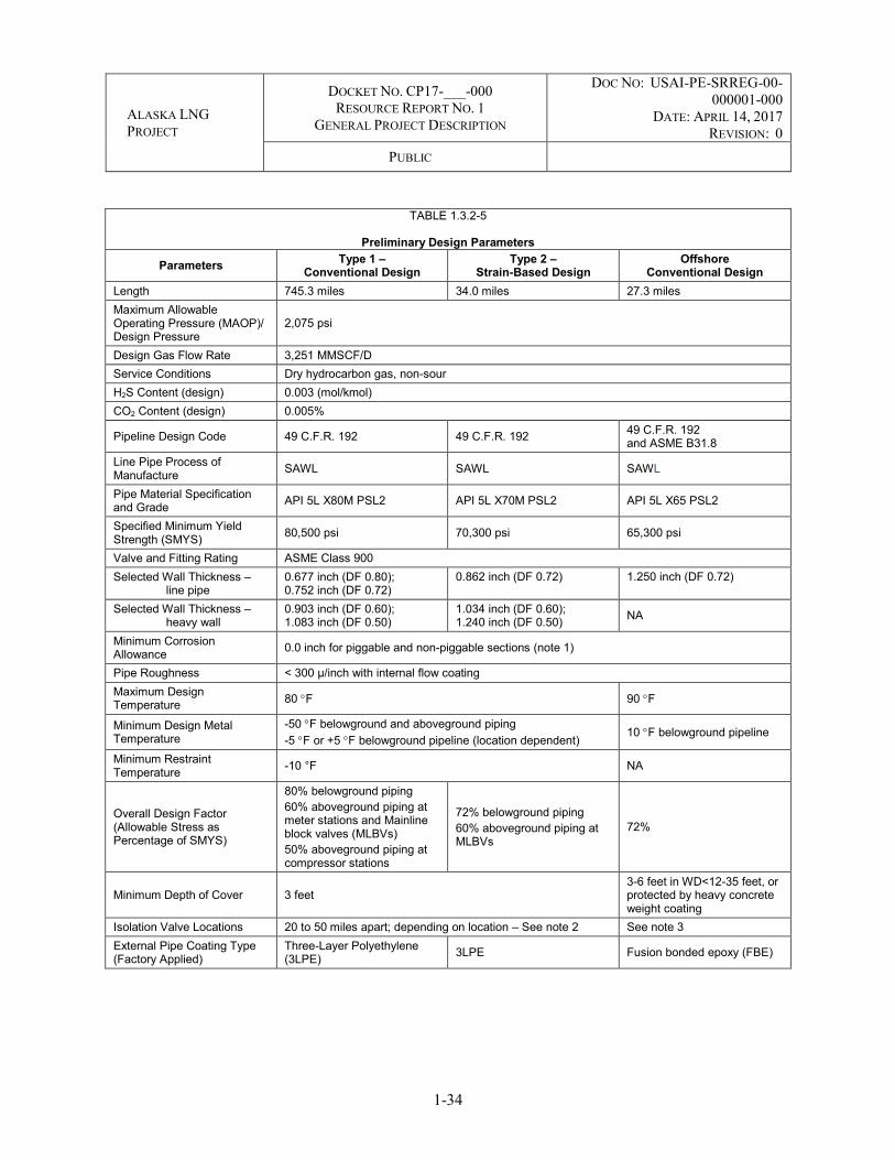
ALASKA LNG PROJECT
DOCKET NO. CP17-___-000 RESOURCE REPORT NO. 1
GENERAL PROJECT DESCRIPTION
DOC NO: USAI-PE-SRREG-00-000001-000
DATE: APRIL 14, 2017 REVISION: 0
PUBLIC
1-34
TABLE 1.3.2-5
Preliminary Design Parameters
Parameters Type 1 – Conventional Design
Type 2 – Strain-Based Design
Offshore Conventional Design
Length 745.3 miles 34.0 miles 27.3 miles Maximum Allowable Operating Pressure (MAOP)/ Design Pressure
2,075 psi
Design Gas Flow Rate 3,251 MMSCF/D Service Conditions Dry hydrocarbon gas, non-sour H2S Content (design) 0.003 (mol/kmol) CO2 Content (design) 0.005%
Pipeline Design Code 49 C.F.R. 192 49 C.F.R. 192 49 C.F.R. 192 and ASME B31.8
Line Pipe Process of Manufacture SAWL SAWL SAWL
Pipe Material Specification and Grade API 5L X80M PSL2 API 5L X70M PSL2 API 5L X65 PSL2
Specified Minimum Yield Strength (SMYS) 80,500 psi 70,300 psi 65,300 psi
Valve and Fitting Rating ASME Class 900 Selected Wall Thickness – line pipe
0.677 inch (DF 0.80); 0.752 inch (DF 0.72)
0.862 inch (DF 0.72) 1.250 inch (DF 0.72)
Selected Wall Thickness – heavy wall
0.903 inch (DF 0.60); 1.083 inch (DF 0.50)
1.034 inch (DF 0.60); 1.240 inch (DF 0.50) NA
Minimum Corrosion Allowance 0.0 inch for piggable and non-piggable sections (note 1)
Pipe Roughness < 300 µ/inch with internal flow coating Maximum Design Temperature 80 F 90 F
Minimum Design Metal Temperature
-50 F belowground and aboveground piping -5 F or +5 F belowground pipeline (location dependent) 10 F belowground pipeline
Minimum Restraint Temperature -10 °F NA
Overall Design Factor (Allowable Stress as Percentage of SMYS)
80% belowground piping 60% aboveground piping at meter stations and Mainline block valves (MLBVs)
50% aboveground piping at compressor stations
72% belowground piping 60% aboveground piping at MLBVs
72%
Minimum Depth of Cover 3 feet 3-6 feet in WD<12-35 feet, or protected by heavy concrete weight coating
Isolation Valve Locations 20 to 50 miles apart; depending on location – See note 2 See note 3 External Pipe Coating Type (Factory Applied)
Three-Layer Polyethylene (3LPE) 3LPE Fusion bonded epoxy (FBE)

ALASKA LNG PROJECT
DOCKET NO. CP17-___-000 RESOURCE REPORT NO. 1
GENERAL PROJECT DESCRIPTION
DOC NO: USAI-PE-SRREG-00-000001-000
DATE: APRIL 14, 2017 REVISION: 0
PUBLIC
1-35
TABLE 1.3.2-5
Preliminary Design Parameters
Parameters Type 1 – Conventional Design
Type 2 – Strain-Based Design
Offshore Conventional Design
____________________ Notes:
1. Non-piggable sections of the pipeline include connection piping to the isolation valve prior scope-break and MLBV by-pass at compressor stations.
2. Pending approval of Special Permit by the Pipeline and Hazardous Materials Safety Administration (PHMSA). 3. Isolation (Block) valves on either shore end of Cook Inlet Crossing
Road, Pipeline, and Utility Crossings
The Mainline would cross numerous roads, railroads, pipelines, utilities, and power lines (see Resource Report No. 8). Design of the road and railroad crossings would be validated for applicability of wall thickness requirements for service loads on crossings in accordance with API RP 1102, using the appropriate design factor for the design class location. The minimum depth of cover would be 4 feet for road crossings and 10 feet for railroad crossings, as specified in Alaska Railroad Corporation (ARRC) standards below travel surface (49 C.F.R. 192 requires a minimum of 3 feet at drainage ditches of public roads and railroads). Specific designs for major highway and railroad crossings are provided in Appendix H.
The general approach for crossing TAPS has been coordinated (see Resource Report 11, Sections 11.7.2.7.3 and 11.7.2.7.4 for information on the TAPS Impact Study) with the TAPS operator, Alyeska Pipeline Service Company (APSC), and would be one of the following two methods, depending on whether TAPS is above ground or below ground at the specific crossing location:
TAPS Belowground Crossing – The preliminary crossing design is to bury the Mainline within a berm so that it crosses over TAPS. The berm would be designed to provide a minimum 3 feet of cover over the Mainline; or
TAPS Aboveground Crossing – The preliminary crossing design is to bury the Mainline so that it crosses at the mid-span between support structures. The crossing angle would depend on the crossing location.
With either crossing alternative, it would be necessary to agree on the approach with APSC. A typical drawing of an aboveground TAPS crossing can be found in Appendix E. A typical drawing of a buried AKLNG pipeline passing over the buried TAPS can also be found in Appendix E.
Crossing of aerial utilities and power line ROWs would be made at approximately the mid-point between the towers that support the overhead lines. This would minimize or remove the possibility of the pipeline interfering with a tower, supporting guy wires, or foundations of the towers. This preliminary crossing design would need to be validated when third-party crossing agreements have been completed.

ALASKA LNG PROJECT
DOCKET NO. CP17-___-000 RESOURCE REPORT NO. 1
GENERAL PROJECT DESCRIPTION
DOC NO: USAI-PE-SRREG-00-000001-000
DATE: APRIL 14, 2017 REVISION: 0
PUBLIC
1-36
1.3.2.1.3 Mainline Aboveground Facilities
The Mainline would include several types of aboveground pipeline facilities. The design would include eight compressor stations, one standalone heater station, two meter stations, multiple pig launching/receiving stations as part of one system (associated with meter stations, GTP, Liquefaction Facility and/or MLBV), multiple MLBVs, and a minimum of five gas interconnection points for in-state deliveries. Three preliminary locations have been identified (see Section 1.1). A list of compressor stations, heater stations, and meter stations is provided in Table 1.3.2-6. The proposed locations of aboveground pipeline facilities are depicted on aerial imagery and USGS maps provided in Appendix A. Preliminary plot plans of aboveground facilities are provided in Appendix B.
TABLE 1.3.2-6
Preliminary Locations of Pipeline Aboveground Facility Stations
Station Type Location (Pipeline MP)
GTP/Mainline Meter Station Meter Station 0.0 Sagwon Compressor Station Compressor Station with Cooling 76.0 Galbraith Lake Compressor Station Compressor Station with Cooling 148.5 Coldfoot Compressor Station Compressor Station with Cooling 240.1 Ray River Compressor Station Compressor Station with Cooling 332.6 Minto Compressor Station Compressor Station with Cooling 421.6 Healy Compressor Station Compressor Station with Cooling 517.6 Honolulu Creek Compressor Station Compressor Station without Cooling 597.4
Rabideux Creek Compressor Station Compressor Station with Heating and without Cooling
675.2
Theodore River Heater Station Heater Station 749.1 Nikiski Meter Station Meter Station 806.6
Facilities would be built on granular pads with the thickness of the granular pads varying depending on site conditions, including the presence and type of permafrost. The type of foundation needed to support aboveground facilities equipment would be based on site-specific subsurface conditions.
Permafrost conditions, ranging between cold, ice-rich to warm, ice-rich, are expected in some areas north of the Honolulu Creek Compressor Station. For these northern locations, adfreeze piles with air space and thermopiles with air space are proposed for the facility design to mitigate heat transfer to the underlying permafrost. The Honolulu Creek Compressor Station and locations to the south would be built on driven steel piles.
Alternate foundation types and various optimizations are possible and would be addressed in later stages of the Project design, incorporating site-specific geotechnical information.
Lighting for Interdependent Project Facilities such as compressor and heater stations is addressed in Section 1.3.2.1.4, with additional details provided in the Lighting Pan in Appendix O of Resource Report 8.

ALASKA LNG PROJECT
DOCKET NO. CP17-___-000 RESOURCE REPORT NO. 1
GENERAL PROJECT DESCRIPTION
DOC NO: USAI-PE-SRREG-00-000001-000
DATE: APRIL 14, 2017 REVISION: 0
PUBLIC
1-37
Compressor Stations
Eight compressor stations would be placed along the Mainline at intervals where natural gas pressure would need to increase to offset the pressure losses caused by friction. The stations would be designed for remote operation and would normally be unmanned. The design for each station includes a turbo-compressor package, which consists of one natural gas-fueled turbine rated between 20,000 and 42,000 horsepower, driving a centrifugal compressor. Station configuration may vary between single units (1 x 100 percent) to multi-unit configuration (2 x 100 percent, 3 x 50 percent). The turbo-compressor package would likely include the following associated equipment:
Gas generator and power turbine skid; Centrifugal compressor skid; Self-cleaning intake air filter and silencer; Electric variable frequency drive starter motor; Gas turbine exhaust gas duct and silencing equipment; Lube oil systems and skids complete with lube oil cooling equipment; and Skid-mounted integral control panels.
The following facilities, equipment, and systems would be located at the compressor stations:
Compressor buildings;
Gas cooling equipment to cool the natural gas leaving station consisting of gas-to-gas exchangers and aerial coolers (specific to the stations with cooling);
Station and unit control systems designed for remote monitoring and operation;
Natural gas engine-driven power generators;
Fuel gas system sourced from the Mainline, for the natural gas turbine;
Utility and power gas systems to provide utility and power gas to auxiliary equipment;
Glycol/hot water system, used for buildings heating, conditioning of fuel gas and turbine g air preheat;
Inlet inline natural gas scrubber;
Aviation, gasoline and/or diesel fuel tanks;
Instrument air system to supply clean, dry, compressed air to control valves, pneumatic instrumentation, and maintenance stations;
Living quarters to provide intermittent accommodation for four to six personnel;
Potable water, wastewater, and solid waste systems;

ALASKA LNG PROJECT
DOCKET NO. CP17-___-000 RESOURCE REPORT NO. 1
GENERAL PROJECT DESCRIPTION
DOC NO: USAI-PE-SRREG-00-000001-000
DATE: APRIL 14, 2017 REVISION: 0
PUBLIC
1-38
Control Room;
Pipeline Pig Launcher and Receiver;
Other structures, such as a storage building, barrel dock, fencing, and exterior lights;
Helicopter landing pad; and
Communication facilities.
Mainline natural gas would enter the compressor station through the station suction isolation valve, after which it would be scrubbed in a suction scrubber to remove any liquids or minor debris. The natural gas would then enter gas-to-gas heat exchangers, to further cool discharged natural gas leaving the compressor station, and then be compressed and discharged to the aerial gas coolers. Cooled natural gas leaving the aerial natural gas coolers is directed through the banks of gas-to-gas heat exchangers for additional cooling prior to leaving the compressor station and entering the pipeline through the discharge isolation valve. Bypass valves would be provided between the inlet and outlet gas-to-gas exchanger headers to allow temperature control to match system operational requirements.
A flow schematic of a typical compressor station with a gas-to-gas and aerial cooling cycle configuration is provided in Figure 1.3.2-1.
FIGURE 1.3.2-1 Flow Schematic for Compressor Station with Gas-to-Gas Cooling
Electric power for the compressor stations would be generated at each site using natural gas engine-driven power generators that would be adequately sized, taking into consideration sparing of units for uninterrupted operation.
MLBV
MAINLINE GAS
COMPRESSOR
SCRUBBER
AERIAL COOLERHEATEXCHANGER

ALASKA LNG PROJECT
DOCKET NO. CP17-___-000 RESOURCE REPORT NO. 1
GENERAL PROJECT DESCRIPTION
DOC NO: USAI-PE-SRREG-00-000001-000
DATE: APRIL 14, 2017 REVISION: 0
PUBLIC
1-39
Gas Temperature Management
To transport natural gas through the pipeline, compression to increase the pressure of natural gas is required at regular intervals. When compressed, the temperature of natural gas increases to a point that could potentially affect the soil surrounding the pipeline, the pipeline material, and pipeline coating. Where the Mainline crosses thaw-sensitive permafrost soils, there is the potential for thaw-induced subsidence, solifluction, and soil creep or thawed layer detachment. In addition, frost bulb development and frost heave could occur in susceptible non-permafrost soils where the pipeline is operated at a mean annual temperature below freezing. These factors have been taken into account for the design and operation of the Mainline, as described below. Additional details on thaw-sensitive permafrost soils and potential impacts are provided in Resource Report No. 7.
Natural gas temperature would be managed by geography, with separate strategies and technologies planned for implementation North and South of the Brooks Range (see Figure 1.3.2-2), described as follows.
From MP 0–MP 180, the pipeline temperature would remain below freezing throughout the year in continuous permafrost. The natural gas in the pipeline would be cooled and maintained to below-freezing temperatures to maintain the stability of thaw-sensitive soils, reducing thaw-related movement of the pipeline and impact to permafrost. For compressor stations with cooling, two types of natural gas cooling equipment are planned: gas-to-gas exchangers and aerial coolers.
From MP 180–MP 567, seasonal variation in natural gas temperatures would range from below freezing in the winter to above freezing in the summer. The in-line temperature in discontinuous permafrost areas was designed for a 32 °F year-round average. This design maintains ground conditions under the pipe close to original conditions.
From MP 567–MP 806, in areas of predominantly warm, non-permafrost conditions, the natural gas temperature would be allowed above freezing temperatures and maintained by using indirect fired natural gas heaters to prevent frost heaving and to meet design inlet natural gas temperature at the LNG Plant.
Heater Stations
As a result of Joule-Thomson cooling19 and pipe-to-soil heat transfer, the temperature of natural gas in the pipeline would generally decrease as it flows through the Mainline. Therefore, gas heating would be required so that the flowing natural gas temperatures are sufficiently high to:
Avoid the freezing of soils adjacent to the pipeline in non-permafrost areas;
Maintain the natural gas temperature above a minimum limit to ensure pipeline fracture toughness; and
19 Joule-Thomson cooling is a thermodynamic process that occurs when a fluid expands from high pressure to low pressure.

ALASKA LNG PROJECT
DOCKET NO. CP17-___-000 RESOURCE REPORT NO. 1
GENERAL PROJECT DESCRIPTION
DOC NO: USAI-PE-SRREG-00-000001-000
DATE: APRIL 14, 2017 REVISION: 0
PUBLIC
1-40
FIGURE 1.3.2-2 Range of Gas Temperatures
Maintain the natural gas temperature above the hydrocarbon dew point temperature to prevent hydrate formation in the natural gas stream.
The design includes the following heating facilities:
Theodore River Heater Station (a standalone heater station); and Heaters installed at the Rabideux Creek Compressor Station.
The heater module package would include the following associated equipment, subject to further study and optimization:
Indirect natural gas-fired heater skid complete with attached horizontal bath vessel; and Burner skid with the exhaust stack.
The following associated facilities would be located at the standalone heater station:

ALASKA LNG PROJECT
DOCKET NO. CP17-___-000 RESOURCE REPORT NO. 1
GENERAL PROJECT DESCRIPTION
DOC NO: USAI-PE-SRREG-00-000001-000
DATE: APRIL 14, 2017 REVISION: 0
PUBLIC
1-41
Instrument and switchgear skid; Gas engine-driven power generators; Utility and power gas system to provide utility and power gas to auxiliary equipment; Other structures, such as a storage building, barrel dock, fencing, and exterior lights; Helicopter landing pad; Aviation, gasoline or diesel fuel tanks; and Communication facilities.
Electric power for the heater station would be generated on site using natural gas engine-driven power generators that would be adequately sized, taking into consideration sparing of units for uninterrupted operation.
Gas Interconnection Points
Interconnection points provide opportunity for connection between the Mainline and any future in-state natural gas treatment facilities and distribution systems that would convey natural gas supplies to utility or industrial users. Currently, there are no known plans for construction of facilities downstream of the interconnection points.
Installation of a tee with an isolation valve(s) would occur at a minimum of five points along the Mainline to allow for future in-state deliveries of natural gas. Gas Interconnection Points are likely to be located near the population centers of Fairbanks, Anchorage, and the Matanuska-Susitna Borough from the north side of Cook Inlet crossing, and the Kenai Peninsula from the south side of the Cook Inlet crossing. Other potential gas interconnection points are also being evaluated. To date, three of the locations for natural gas interconnection points have been identified:
Fairbanks/North Star Gas Interconnection Point – near MP 441 to serve the Fairbanks area;
Anchorage/Matanuska-Susitna Gas Interconnection Point – near MP 764 to connect to the existing ENSTAR pipeline system for delivery to serve the Anchorage/Matanuska-Susitna Valley area; and
Kenai Peninsula Gas Interconnection Point – near MP 806 to connect to the existing ENSTAR pipeline system to serve the Kenai Peninsula area.
1.3.2.1.4 Lighting
Lighting at pipeline aboveground facilities would meet regulatory requirements, codes, and standards for lighting generally established for overall site operations/maintenance, safety, and security. In addition, lighting would be designed to address guidance provided by the USFWS as practicable to reduce potential impacts on birds and other wildlife.
To the extent practical, lighting design for these facilities would minimize projection outward to avoid impacts to wildlife. Final location, number of lights, and shielding installation would be determined as engineering progresses through later stages of the Project.

ALASKA LNG PROJECT
DOCKET NO. CP17-___-000 RESOURCE REPORT NO. 1
GENERAL PROJECT DESCRIPTION
DOC NO: USAI-PE-SRREG-00-000001-000
DATE: APRIL 14, 2017 REVISION: 0
PUBLIC
1-42
Additional details on lighting are provided in the Lighting Plan in Appendix O of Resource Report No. 8.
1.3.2.2 Prudhoe Bay Gas Transmission Line (PBTL)
The GTP and associated facilities, located in the PBU, would receive natural gas from the PBU by way of the PBTL. The PBTL would be an approximately 1-mile, 60-inch-diameter aboveground pipeline to transport natural gas from the PBU Central Gas Facility (CGF) to the GTP, with an average stream day rate of 2.8 BSCF/D, a peak capacity of 4.0 BSCF/D20 and a MAOP of 720 psig. The PBTL would be constructed compliant with the National Association of Corrosion Engineers (NACE) MR0175 Sour Service Specification. The PBTL would be installed on horizontal support members connected to a steel pile, or vertical support members (VSMs), and would be located within the North Slope Borough, crossing lands managed by the State of Alaska.
A typical VSM is illustrated in Appendix E. The VSM would be embedded and slurried at a specified depth in the ground. Design of the supports would be in accordance with appropriate codes and standards, and information received from the geotechnical and hydrology reports.
The PBTL route would begin at the edge of the PBU CGF pad and proceed west to the tie-in point at the GTP. The new pipeline would maintain a minimum of 7 feet from the tundra to the bottom of the pipe.
1.3.2.3 Point Thomson Gas Transmission Line (PTTL)
The GTP and associated facilities, located in the PBU, would receive natural gas from the PTU by way of the PTTL. The PTTL would be an approximately 62.5-mile, 32-inch-diameter aboveground pipeline. Because the PTU facilities are not designed to remove H2S, the proposed PTTL would be designed to carry small concentrations of H2S that may be contained in gas received from the PTU. The PTTL would be constructed compliant with NACE MR0175 Sour Service Specification to provide mitigation for internal corrosion and stress cracking in the event of a process upset or the unplanned introduction of free water into the system. The PTTL design includes an average stream day rate of 865 million standard cubic feet per day (MMSCF/D),21 a peak capacity of 920 MMSCF/D,22 and an MAOP of 1,150 psig.
The PTTL would be located between the PTU and the GTP at Prudhoe Bay, aligned east-west and parallel to the coast of the Beaufort Sea (see Figure 1.1-1 and Appendix A mapbooks). The PTTL would be located entirely within the North Slope Borough, crossing lands managed by the State of Alaska.
The PTTL would begin at the Point Thomson Central Pad, and travel parallel to the existing and operating Point Thomson Export Pipeline until Badami, where it would deviate south to avoid existing infrastructure and align for the crossing of the East Badami Creek. The route then parallels the Badami Sales Oil Pipeline
20 Average stream day rate denotes the weighted 12-month average of monthly stream day rate values. Stream day rate represents the physical capacity of the facility at a particular ambient condition and does not account for planned or unplanned downtime (assume 100-percent uptime).
21 Variability due to changes in in-state gas interconnection points over 30-year design life. 22 Average stream day rate denotes the weighted 12-month average of monthly stream day rate values. Stream day rate represents the physical
capacity of the facility at a particular ambient condition and does not account for planned or unplanned downtime (assume 100-percent uptime).

ALASKA LNG PROJECT
DOCKET NO. CP17-___-000 RESOURCE REPORT NO. 1
GENERAL PROJECT DESCRIPTION
DOC NO: USAI-PE-SRREG-00-000001-000
DATE: APRIL 14, 2017 REVISION: 0
PUBLIC
1-43
until the East Sagavanirktok River where it heads south to better align for the crossing. The PTTL then proceeds northwest and follows existing infrastructure into the Prudhoe Bay area.
The PTTL would be installed on VSMs (see Typical ROW configuration in Appendix E). The VSM would be embedded and backfilled with a slurry granular material mix designed for freezing in permafrost soils at a specified depth in the ground. Excess fill would be taken to an approved disposal site. To account for potential permafrost thawing, the PTTL design basis would conservatively embed the VSM below the surface. Design of the supports would be in accordance with appropriate codes and standards, and information received from the geotechnical and hydrology reports. No heat pipes or other refrigeration methods are anticipated for the VSMs. The bottom of the pipeline would be elevated a minimum of 7 feet above the ground surface.
As detailed in Resource Report No. 2, the PTTL would cross several named waterbodies. Three crossings (i.e., Shaviovik River, Kadleroshilik River, and Sagavanirktok River Main Channel) would be buried with conventional open-cut methods in the winter, as depicted in Resource Report No. 2, Appendix I –Site Specific Waterbody Crossing Plans. The remaining crossings, including the West Channel of the Sagavanirktok River, an Unnamed Tributary to Putuligayuk River, and the Putuligayuk River, would be installed with aboveground pipeline crossings. The West Channel of the Sagavanirktok River would be crossed by adding structural extensions to an existing pipeline bridge, while the Putuligayuk River and its unnamed tributary would be crossed using standard VSMs.
The proposed route of the PTTL is located near active hunting areas; therefore, the PTTL design provides for X65 grade, 0.5-inch wall thickness pipe, which is considered bullet resistant for rifle calibers and ammunition typically used in the area.
Cathodic protection would not be required for the aboveground portions of the PTTL. Cathodic protection would be required for any buried sections of pipe, including buried watercourse crossings. A passive cathodic protection system using sacrificial anodes would be used. A passive system requires no external power supply. Sacrificial anodes are typically made of magnesium, zinc, or aluminum and are bonded to the protected structure. In this system, the elemental electronegativity of the anode metal and the protected structure causes a current flow from the anode to the cathode (protected structure). As the current flows from the anode, it is slowly consumed. The rate of the anode consumption is dependent upon the soil resistivity and acidity; therefore, it requires proper anode sizing and design to ensure ability to meet its intended design life.
The cathodic protection system test stations, positioned on aboveground posts, would be located at any major river crossing and any crossing with foreign structures.
1.3.2.3.1 PTTL Aboveground Facilities
Intermediate natural gas compression or cooling facilities are not planned for the PTTL. There would be one meter station associated with this pipeline that would be built on the existing PTU Central Pad pad. The PTTL would be designed to allow passage of in-line inspection and maintenance tools. A launcher located at the PTU meter station and a receiver located at the GTP inlet are currently planned. There are three MLBVs selected based on the valve spacing requirements of 49 C.F.R. 192.179 and two isolation/sectionalizing valves coinciding with the PTU meter station and GTP inlet. The preliminary design for the standalone block valve assemblies currently consists of an aboveground MLBV, blowdown

ALASKA LNG PROJECT
DOCKET NO. CP17-___-000 RESOURCE REPORT NO. 1
GENERAL PROJECT DESCRIPTION
DOC NO: USAI-PE-SRREG-00-000001-000
DATE: APRIL 14, 2017 REVISION: 0
PUBLIC
1-44
risers on each side of the valve, and a cross-over between the risers. Control systems on MLBV assemblies would include local low pressure monitoring and, in the event of loss of inventory, automatic valve closure occurs. MLBV assemblies would be placed on a platform adjacent to an anchor support.
The preliminary design for the isolation/sectionalizing valve and trap assembly at the PTU meter station consists of a launcher trap placed in parallel with an isolation/sectionalizing valve assembly. The preliminary design for the isolation/sectionalizing valve and trap assembly at the GTP inlet consists of a receiver trap placed in parallel with an isolation/sectionalizing valve assembly.
1.3.2.4 Temporary Pipeline Construction Infrastructure
Construction of each pipeline would require the use of additional temporary facilities and other resources in the area of the permanent pipeline ROW (see mapping with most current alignment and project footprint in Appendix A). The associated infrastructure may include the following facilities, which are discussed in more detail below and in later sections of this report:
Temporary workspace for construction activities (e.g., staging areas, truck turnarounds, and utility crossovers);
Access roads and shoo-flies (i.e., temporary roads bypassing constrained sections of the construction ROW), to transport equipment, material, pipe, and personnel to the Project area, some of which may be retained for permanent use during operations (see Appendix F for Mainline and PTTL Access Roads). Access roads are discussed in the Project Access Roads section of Section 1.3.4;
Water sourcing facilities to support camp raw water supply, snow and ice road construction, hydrostatic testing activities, earthwork moisture conditioning, and dust control (See preliminary information in the Water Use Plan in Resource Report No. 2);
Helipads to transport personnel to remote locations (see Table 1.3.5-1 for the Mainline in Section 1.3.5);
Airstrips for transporting personnel and freight to and from the Project area (See Table 1.3.6-1 for the Mainline in Section 1.3.6, none for other pipelines);
Construction camps (to house workers in remote areas);
Pipe storage areas (for stockpiling pipe prior to installation);
Contractor yards (for construction staging, material storage, and other contractor needs);
Rail spurs (to facilitate offload of pipe and other materials) (see Table 1.3.2-10 and Appendix I);
Equipment fueling facilities;

ALASKA LNG PROJECT
DOCKET NO. CP17-___-000 RESOURCE REPORT NO. 1
GENERAL PROJECT DESCRIPTION
DOC NO: USAI-PE-SRREG-00-000001-000
DATE: APRIL 14, 2017 REVISION: 0
PUBLIC
1-45
Existing and new material sites to supply sand, granular material, and rock/stone for construction of the pipeline and related facilities described in Section 1.3.7 (see also Gravel Sourcing Plan and Reclamation Measures in Resource Report No. 6, Appendix F);
Disposal sites for excavated material, stumps, blast rock, acid drainage rock, and slash removed from the permanent pipeline ROW (general procedures that will be followed are provided in the Waste Management Plan located in Resource Report No. 8, Appendix J); and
Pipe coating yards and concrete coating facilities. Pipe coating yard location(s) are anticipated to be within developed areas with access to commercial utilities. Any utilities not available commercially will be developed by the project..
1.3.2.4.1 Mainline MOF
A Mainline MOF may be required on the west side of Cook Inlet in proximity to the offshore pipeline shore crossing to support onshore and offshore pipeline and facilities construction activities. These construction activities include the offshore shoreline crossing, as well as onshore construction between the shoreline crossing and the Yentna River. All of the supporting equipment, materials, and supplies would need to be delivered by water or by air because the west side of Cook Inlet, where the Project would cross, is not connected to any other area of the state by road. The purpose of the Mainline MOF would be to provide a marine offloading and backhaul loading point for construction equipment and consumables, fuel, camp components, personnel, line pipe, and other construction materials.
At the proposed Mainline MOF location, there is an existing Beluga barge landing facility. However, it is not considered feasible to use the existing facility due to its current high level of utilization and its lack of a robust landing area suitable for larger barges. In addition, the existing access road, facility, and landing would not be suitable for cargo offloading. There is a steep gradient at the landing and sharp bends in the access road. The existing barge landing would be used as an offloading and backhaul point during initial Mainline MOF construction.
The Mainline MOF would be located close to, but at a reasonable distance from, the current Beluga barge landing facility such that construction and operation of the MOF would not interfere with current dock operations. The MOF would consist of berths and space for tugs including:
Lo-Lo Berth for unloading pipes and construction materials; and Ro-Ro Berth and ramp dedicated to Ro-Ro operations.
The overall size of the Mainline MOF would be approximately 600 feet long by 400 feet wide, including an adjacent Ro-Ro ramp. Access roads would be constructed that lead from the MOF to a planned material laydown area that connects to the local road system.
Due to the shallow water at landing site, it is assumed that barges delivering cargo would be grounded at the berths during low tide. An exception would be Ro-Ro barges or vessels, which would be restricted to the tidal window in which they can operate. No dredging is proposed to enhance barge docking capabilities, however adequate fill from onshore would be added at the landing to enable a barge to ground itself and provide for offloading capability.

ALASKA LNG PROJECT
DOCKET NO. CP17-___-000 RESOURCE REPORT NO. 1
GENERAL PROJECT DESCRIPTION
DOC NO: USAI-PE-SRREG-00-000001-000
DATE: APRIL 14, 2017 REVISION: 0
PUBLIC
1-46
The permanent Mainline MOF is anticipated to consist of:
Two 30-foot-wide access roads cut through the existing bluff and leading to a quay; A quay constructed as a gravity structure formed by an anchored sheet-pile wall; A Ro-Ro ramp consisting of anchored sheet pile construction that abuts the quay; and Surfacing on the quay and access roads consisting of graded crushed rock.
1.3.2.4.2 Pipeline Fuel Demand and Storage
The estimated diesel fuel demand for Mainline construction is provided in Table 1.3.2-7.
TABLE 1.3.2-7
Estimated Diesel Fuel Demand for Mainline and Aboveground Facility Constructiona Development of Construction Infrastructure (Civil Spreads) 18,430 gallons per day Pipeline Spreads (Spread is a unit of construction activity by mileage or location) 26,950 gallons per day Facilities Spreads 4,260 gallons per day Pioneer Camps
9,650 gallons per day Mainline Camps Facilities Camps __________________ a Preliminary construction estimates
During development of construction infrastructure, one 10,000-gallon skidded horizontal fuel storage tank would be supplied for each pioneer camp and two 20,000-gallon skidded horizontal fuel storage tanks for each civil construction spread. In addition to the diesel storage, one 500-gallon gasoline storage tank would be provided at each site. For multi-tank installations, the tanks would be connected with piping. The tanks and connecting piping system would also have secondary spill containment in accordance with federal and state requirements.
During the four-season construction of the Mainline, two 20,000-gallon storage tanks would be set up at each pipeline construction camp site and five 20,000-gallon storage tanks at contractor yards for each construction spread, based on a five-day contingency volume. The storage tanks would be located within secondary containment. In addition to the diesel storage, one 500-gallon gasoline storage tank would be provided at each site for small tools and other miscellaneous needs.
Temporary fuel depots would be situated along the Dalton Highway and would provide not only fueling for transport trucks, but would also provide additional fuel storage for the crews should there be an interruption in supply from Fairbanks. The majority of the tanks would be moved approximately every six months (i.e., when the camps are moved); however, interim storage tanks may remain in place for three to four years.
Each active bulk fuel storage site would be operated in compliance with local borough, state, and federal regulatory requirements, and the Project’s SPCC Plan (Resource Report No. 2, Appendix M). Oil-handling personnel would be trained in the operation and maintenance of equipment to prevent discharges in

ALASKA LNG PROJECT
DOCKET NO. CP17-___-000 RESOURCE REPORT NO. 1
GENERAL PROJECT DESCRIPTION
DOC NO: USAI-PE-SRREG-00-000001-000
DATE: APRIL 14, 2017 REVISION: 0
PUBLIC
1-47
accordance with 18 Alaska Administrative Code 75.020 as well as oil discharge prevention training and recordkeeping and 40 C.F.R. 112.7 (f) personnel, training, and discharge prevention procedures.
Temporary tanks with secondary containment are planned for preconstruction and construction fuel requirements. The tanks would be removed following construction.
Table 1.3.2-8 lists the number of diesel storage tanks that would be required, based on the assumption of five-day storage at each site and at the interim terminals.
TABLE 1.3.2-8
Estimated Number of Diesel Storage Tanksa for Mainline Construction
Tank Location 10,000 Gallons Tanks
20,000 Gallons Tanks
30,000 Gallons Tanks Number of Tanks
Pioneer Camp 19 34 0 51 Pipeline Camp 0 31 0 31 Facility Camp 6 0 0 6 Interim Storage Locations 0 0 25 27 Total 25 65 25 115 __________________ Notes: a Preliminary construction estimates
Table 1.3.2-9 lists the number of gasoline storage tanks that would be required, based on the assumption of small tools usage at each site.
TABLE 1.3.2-9
Estimated Number of Gasoline Storage Tanksa for Mainline Construction Tank Location Tanks per Location Number of Locations
Pioneer Camp 1 19
Pipeline Camp 1 6
Facility Camp 1 3
Total
28
__________________ Notes: a Preliminary construction estimates
1.3.2.4.3 Construction Camps, Pipe Storage Areas, Contractor Yards, and Rail Spurs
The Project would require the use of construction camps, pipe storage areas, contractor yards, and rail spurs listed in Table 1.3.2-10 for construction of the pipelines described in this Resource Report. The general locations of these temporary construction infrastructure facilities are identified on the facility location maps included as Appendix A. Land use descriptions of these facilities are included in Resource Report No. 8.

ALASKA LNG PROJECT
DOCKET NO. CP17-___-000 RESOURCE REPORT NO. 1
GENERAL PROJECT DESCRIPTION
DOC NO: USAI-PE-SRREG-00-000001-000
DATE: APRIL 14, 2017 REVISION: 0
PUBLIC
1-48
Typical layouts for these facilities are included in Appendix E. Construction camps and storage facilities for the GTP and Liquefaction Facility are provided in their respective sections and are found on the proposed sites. The construction of the PBTL and Byproducts pipelines would use the camps for the GTP as well as laydown areas on the GTP site and possibly on the PBU CGF pad.
Future design phases and construction contracting may warrant additional pipe, rail, and contractor yards beyond those currently identified. If changes are required, c Project representatives would file an updated list of work areas, including construction camps, pipe, rail, and contractor yards prior to use for FERC approval.
TABLE 1.3.2-10
Preliminary Pipeline Construction Camps, Pipe Storage Areas, Contractor Yards, and Rail Spurs
Borough or Census Area/Facility Name
Approximate Mileposta
Distance (miles) and Direction from
Mainlineb Camp Pipe Storage
Area Contractor
Yard Rail Spurs Existing or Previously
Used Facility
NORTH SLOPE--Mainline
Prudhoe Bay 0.7 0.39 W No Sag River Floodplain 24.7 0.95 E No Franklin Bluffs 43.6 0.23 E Yes Sagwon 66.8 1.00 W Yes Sagwon Compressor Station 76 0.06 W No Happy Valley 85.8 0.77 E Yes Kakuktukruich Bluff 96.8 1.10 E No Slope Mountain 114.5 0.57 E No Toolik Hills 129.6 0.13 W No Galbraith Lake 142.5 1.80 W Yes Galbraith Lake Compressor Station 148.5 0.02 W No Atigun 166.1 0.25 W Yes Chandalar 174.6 0.04 W No
YUKON-KOYUKUK
Tracey's Trickle 190.9 0.10 W No Disaster Creek 205 0.08 W No Dietrich 205.9 0.35 W Yes Gold Creek 218.8 0.27 E Yes Coldfoot Compressor Station 240.1 0.06 W No
Coldfoot 241.1 0.16 W (partial,
regrown) Crossroads Creek 255.3 0.31 W Yes Prospect 278.9 1.35 W Yes Alder Mountain 296.7 0.53 W Yes Old Man 305.7 0.18 W Yes
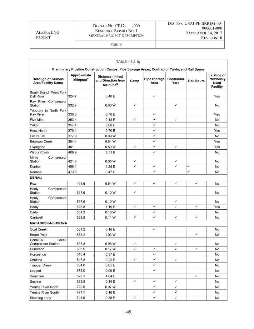
ALASKA LNG PROJECT
DOCKET NO. CP17-___-000 RESOURCE REPORT NO. 1
GENERAL PROJECT DESCRIPTION
DOC NO: USAI-PE-SRREG-00-000001-000
DATE: APRIL 14, 2017 REVISION: 0
PUBLIC
1-49
TABLE 1.3.2-10
Preliminary Pipeline Construction Camps, Pipe Storage Areas, Contractor Yards, and Rail Spurs
Borough or Census Area/Facility Name
Approximate Mileposta
Distance (miles) and Direction from
Mainlineb Camp Pipe Storage
Area Contractor
Yard Rail Spurs Existing or Previously
Used Facility
South Branch West Fork Dall River 324.7 0.40 E Yes Ray River Compressor Station 332.7 0.06 W No Tributary to North Fork Ray River 336.3 0.70 E Yes Five Mile 353.4 0.18 E No Yukon 357.4 0.08 E No Hess North 370.1 0.70 E Yes Future CS 377.9 0.09 W No Erickson Creek 394.4 0.84 W Yes Livengood 401 0.50 W Yes Wilbur Creek 409.9 3.51 E No Minto Compressor Station 421.6 0.05 W No Dunbar 456.1 1.25 E No Nenana 473.6 0.47 E No
DENALI Rex 498.6 0.64 W No Healy Compressor Station 517.6 0.10 W No Healy Compressor Station 517.6 0.10 W No Healy 528.8 1.19 E Yes Carlo 551.2 0.16 W No Cantwell 568.8 0.11 W No
MATANUSKA-SUSITNA
Coal Creek 581.2 0.16 E No Broad Pass 583.2 1.03 W No Honolulu Creek Compressor Station 597.3 0.06 W No Hurricane 606.9 0.17 W No Horseshoe 618.4 0.37 E No Chulitna 647.8 0.22 E No Trapper Creek 664.6 0.05 E No Logged 672.0 0.06 E No Sunshine 676.1 4.04 E No Susitna 693.5 0.14 E No Yentna River North 720.6 0.07 W No Yentna River South 721.5 0.16 E No Sleeping Lady 744.9 0.35 E No

ALASKA LNG PROJECT
DOCKET NO. CP17-___-000 RESOURCE REPORT NO. 1
GENERAL PROJECT DESCRIPTION
DOC NO: USAI-PE-SRREG-00-000001-000
DATE: APRIL 14, 2017 REVISION: 0
PUBLIC
1-50
TABLE 1.3.2-10
Preliminary Pipeline Construction Camps, Pipe Storage Areas, Contractor Yards, and Rail Spurs
Borough or Census Area/Facility Name
Approximate Mileposta
Distance (miles) and Direction from
Mainlineb Camp Pipe Storage
Area Contractor
Yard Rail Spurs Existing or Previously
Used Facility
KENAI PENINSULA
Theodore River Heater Station 749.0 0.16 E No Beluga Marine Camp 766.1 0.14 E No Kenai 803.5 0.21 E No
NORTH SLOPE--PTTL PTTL Prudhoe Bay 18.9 0.47 N No Sag Delta Camp 49.3 0.15 N No Badami 53.7 1.23 SW No
_________________ a PTTL milepost 0.0 starts at the PTU. b N - North, E - East, S - South, W - Westall
Construction Camps
Temporary construction camps would be used to house personnel during construction of the Mainline and associated aboveground facilities. Each camp would be fully self-sustaining with fuel storage, power generation, water treatment, food preparation, and wastewater treatment facilities.
Numerous camps would be required to accommodate the number of construction and support personnel required for Project construction (see Table 1.3.2-10 and Appendix I). Camp sizes would depend on the construction activity and locations that they are supporting. Three types of camps would be needed:
Pioneer (or mobile) camps to house personnel involved in development of construction infrastructure such as developing borrow source material sites, constructing camps, access roads, storage and staging sites;
Main camps for Mainline and PTTL construction; and
Facilities camps for aboveground facility construction.
Pioneer camps would be installed approximately two to three years prior to pipeline construction to support preparing the camp sites and camps, access roads, pipe yards, and extracting the granular material required for construction. Pioneer camps would consist of 120-person, skid-mounted units and would occupy approximately 3 acres of land. Once the pads have been developed, these pioneer camps would be used for pipe and equipment hauls, as well as housing personnel used for the construction of the larger main camps. Once the main camps are operational, the pioneer camps may be relocated depending on the construction plan. However, a number of the pioneer camps would remain in place to support the last year’s work of restoration and cleanup requirements.

ALASKA LNG PROJECT
DOCKET NO. CP17-___-000 RESOURCE REPORT NO. 1
GENERAL PROJECT DESCRIPTION
DOC NO: USAI-PE-SRREG-00-000001-000
DATE: APRIL 14, 2017 REVISION: 0
PUBLIC
1-51
Main camps would occupy approximately 35 acres of land and house approximately 1,200 persons, depending on construction requirements. The camps would consist of camp modules that are transportable by truck and placed on timbers for leveling and drainage (see Appendix E, Typical Drawings).
Facilities camps (240 personnel on average) would support heater station, meter station, MLBVs, and compressor station construction. Generally, these camps would be located on or adjacent to facility sites and would occupy up to 8 acres. Camps established for construction of compressor stations and heater stations would be situated within the station permanent fencing.
Proposed construction camps would use wastewater treatment systems that primarily use filtration for treatment. The resulting treated water would be discharged per Alaska Pollutant Discharge Elimination System (APDES)/National Pollutant Discharge Elimination System (NPDES) permit requirements and the resulting solids would be incinerated or transported for disposal at an approved facility. This concept for sanitary systems would be further developed in later stages of the Project design, and would meet applicable permitting requirements.
Pipe Storage Areas
Pipe storage areas approximately 6 to 15 acres in size would be constructed to store pipe that would ultimately be delivered to the ROW. Pipe would typically be delivered in double-jointed (80-foot nominal, 76-foot estimated) lengths. Exceptions would include allotments of double-random (40-foot nominal, 38-foot estimated) joints to be used for concrete coated crossings, test manifolds, steep terrain, valve pups, and other locations, and possibly some allotments of triple random joints to be used in the stress-based design areas.
Contractor Yards
Contractor yards would be required for staging, material storage, and other contractor needs. Contractor yards would be collocated with camps or pipe storage yards. Overall size of the combined camp contractor yard would vary from 20 to 35 acres depending on camp option selected.
Rail Spurs
It is planned to receive the line pipe and major equipment in Seward and then transfer materials to Fairbanks via the Alaska Railroad system. Most movement would be between existing facilities at Seward and Fairbanks, but some of the line pipe would be delivered to newly built railroad spurs. Eight sidings (i.e., relatively short stretch of track used to store cars or enable trains on the same line to pass) have been identified (Table 1.3.2-10) that are located in proximity to the ROW and pipe storage yards. A spur would be added to each of these sidings to facilitate the unloading of Project material onto a newly built granular pad.
1.3.2.5 Mainline Block Valves (MLBVs)
MLBVs would be used to segment the Mainline for safety, operations, and maintenance purposes. MLBVs would be sited at locations to meet regulatory, operational, and engineering requirements (Table 1.3.2-11). One MLBV would be located at each compressor station and heater station, and the remaining MLBVs

ALASKA LNG PROJECT
DOCKET NO. CP17-___-000 RESOURCE REPORT NO. 1
GENERAL PROJECT DESCRIPTION
DOC NO: USAI-PE-SRREG-00-000001-000
DATE: APRIL 14, 2017 REVISION: 0
PUBLIC
1-52
would be standalone facilities along the Mainline. MLBVs would be automated only to the extent that they would close for line break detection (i.e., a set low pressure condition). Line break detection would be installed on MLBVs to detect and close the valve in the event of line rupture. No remote-control capability to control the valves is proposed.
Each MLBV site would also typically include blowdown valves to evacuate gas and a line break control system to close the valve upon detection of a low-pressure condition. A helipad would also be located adjacent to each MLBV site (see Table 1.3.5-1).
TABLE 1.3.2-11
Preliminary Aboveground Facilities Associated with the Mainline – MLBV, Launchers/Receivers, Gas Interconnection Pointsa
Facility Type/Facility Name Milepostb Borough or Census Area
Mainline Block Valves
MLBV 1 0.00 North Slope
MLBV 2 36.74 North Slope
MLBV 3 75.97 North Slope
MLBV 4 112.04 North Slope
MLBV 5 148.51 North Slope
MLBV 6 194.09 Yukon-Koyukuk
MLBV 7 240.10 Yukon-Koyukuk
MLBV 8 286.05 Yukon-Koyukuk
MLBV 9 332.64 Yukon-Koyukuk
MLBV 10 377.95 Yukon-Koyukuk
MLBV 11 421.56 Yukon-Koyukuk
MLBV 12 444.90 Yukon-Koyukuk
MLBV 13 467.10 Yukon-Koyukuk
MLBV 14 492.96 Denali
MLBV 15 517.62 Denali
MLBV 16 534.79 Denali
MLBV 17 538.79 Denali
MLBV 18 546.50 Denali
MLBV 19 572.23 Denali
MLBV 20 597.35 Matanuska-Susitna
MLBV 21 625.83 Matanuska-Susitna
MLBV 22 648.16 Matanuska-Susitna
MLBV 23 675.24 Matanuska-Susitna
MLBV 24 703.67 Matanuska-Susitna
MLBV 25 725.93 Matanuska-Susitna

ALASKA LNG PROJECT
DOCKET NO. CP17-___-000 RESOURCE REPORT NO. 1
GENERAL PROJECT DESCRIPTION
DOC NO: USAI-PE-SRREG-00-000001-000
DATE: APRIL 14, 2017 REVISION: 0
PUBLIC
1-53
TABLE 1.3.2-11
Preliminary Aboveground Facilities Associated with the Mainline – MLBV, Launchers/Receivers, Gas Interconnection Pointsa
Facility Type/Facility Name Milepostb Borough or Census Area
MLBV 26 749.11 Matanuska-Susitna
MLBV 27 766.01 Kenai Peninsula
MLBV 28 793.34 Kenai Peninsula
MLBV 29 799.85 Kenai Peninsula
MLBV 30 806.57 Kenai Peninsula
Launchers and Receivers
Launcher at GTP Mainline Meter Station 0.00 North Slope
Receiver and Launcher at Sagwon Compressor Station 75.97 North Slope
Receiver and Launcher at Galbraith Lake Compressor Station 148.51 North Slope
Receiver and Launcher at Coldfoot Compressor Station 240.10 Yukon-Koyukuk
Receiver and Launcher at Ray River Compressor Station 332.64 Yukon-Koyukuk
Receiver and Launcher at Minto Compressor Station 421.56 Yukon-Koyukuk
Receiver and Launcher at Healy Compressor Station 517.62 Denali
Receiver and Launcher at Honolulu Creek Compressor Station 597.36 Matanuska-Susitna
Receiver and Launcher at Rabideux Creek Compressor Station 675.23 Matanuska-Susitna
Receiver and Launcher at Theodore River Heater Station 749.12 Matanuska-Susitna
Receiver at Nikiski Meter Station 806.57 Kenai Peninsula
Gas Interconnection Points
Fairbanks/North Star Gas Interconnection Point 441.12 Yukon-Koyukuk
Anchorage/Matanuska-Susitna Gas Interconnection Point 764.26 Kenai Peninsula
Kenai Peninsula Gas Interconnection Point 806.57 Kenai Peninsula __________________ Notes: a Cathodic protection facilities would be installed at the MLBV, compressor station, and meter station sites. Test lead posts
would be distributed along the permanent ROW. b Mainline Milepost 0.0 starts at the GTP.
1.3.2.6 Launchers/Receivers
The Mainline would be designed to allow passage of in-line inspection tools and cleaning pigs. Launchers and receivers installed along the pipeline to launch and receive the inspection tools and pigs are planned along the pipeline to facilitate cleaning and integrity management operations. Mainline launcher/receivers would be installed at compressor stations and meter stations (see Table 1.3.2-11).

ALASKA LNG PROJECT
DOCKET NO. CP17-___-000 RESOURCE REPORT NO. 1
GENERAL PROJECT DESCRIPTION
DOC NO: USAI-PE-SRREG-00-000001-000
DATE: APRIL 14, 2017 REVISION: 0
PUBLIC
1-54
1.3.2.7 Cathodic Protection Facilities
A cathodic protection system to mitigate external corrosion for the Mainline facilities would be installed and maintained in accordance with applicable codes and regulations, including 49 C.F.R. Part 192 Transportation of Natural Gas and Other Gas by Pipeline: Minimum Federal Safety Standards, NACE SP0169 Control of External Corrosion on Underground or Submerged Metallic Piping Systems, and NACE SP0177 Mitigation of Alternating Current and Lightning Effects on Metallic Structures and Corrosion Control Systems.
In addition to protecting a buried steel pipeline from corrosion, the cathodic protection system must also address:
Stray current interference from TAPS, or other pipelines; Alternating Current mitigation near overhead powerlines; and Telluric currents.
Cathodic protection system facilities (e.g., groundbeds and rectifiers) associated with the Mainline would be located at selected compressor stations, meter stations, and MLBV sites to the extent practical.
1.3.2.7.1 Pipeline Corrosion Protection
The use of one of the following cathodic protection system, or combination of cathodic protection systems, would be used to protect the buried pipeline:
Sacrificial anodes – Installed closely and parallel to the pipeline at designated intervals, these anodes are a dissimilar metal from the pipeline. The naturally occurring underground corrosion cycle would deplete (sacrifice) or corrode the anode to protect the pipe;
Deep-well or other remote groundbed systems – This type system is commonly referred to as an Impressed Current system. An Impressed Current rectifier uses an external power source to develop a high electrical potential between the pipeline and a deep-well anode bed. The higher current output from the anode bed to the pipeline enhances the protection of the pipeline; and
A hybrid of these two systems.
The type of cathodic protection system would depend on the type of soil, soil characteristics, length of pipeline segment to be protected, and nearby structures.
1.3.2.7.2 Stray Current Interference
Interference would be mitigated primarily by one or more of the following methods:
Selection of groundbed location – Ensuring that groundbeds are a safe distance from foreign structures (including other pipelines). Stray current considerations are a fundamental aspect of detailed cathodic protection design, particularly groundbed design and location;

ALASKA LNG PROJECT
DOCKET NO. CP17-___-000 RESOURCE REPORT NO. 1
GENERAL PROJECT DESCRIPTION
DOC NO: USAI-PE-SRREG-00-000001-000
DATE: APRIL 14, 2017 REVISION: 0
PUBLIC
1-55
Resistive bonding – If necessary, resistive bonding may be installed between the pipeline and the foreign structure. This is an electrical bonding of the structures thus eliminating stray currents between them. The resistivity of the bond must be adjusted so that each structure maintains the designed level of cathodic protection; and
Dielectric shielding – Electrically insulating material (e.g., robust coating) may be considered near known pipeline crossings to lower the risk of stray current interference.
1.3.2.7.3 Alternating Current Mitigation
Alternating Current interference would be a consideration when the Mainline ROW is in proximity to overhead power lines. Problematic locations would be identified and evaluated during a later stage of the Project design. Alternating Current mitigation systems would be designed by a qualified cathodic protection design firm and installed in locations with identified Alternating Current interference issues.
1.3.2.7.4 Telluric Currents
Telluric currents can form in long buried electrical conductors, such as pipelines. Telluric currents are induced by placing the conductor in the earth’s magnetic field. Tellurics can occasionally disrupt cathodic protection monitoring and control systems. Telluric signals would be mitigated by one or more of the following methods:
Grounding – Anode beds can be used to drain telluric currents to ground; and/or
IC rectifiers and associated groundbeds – Rectifiers of sufficient capacity can be installed to dampen current swings driven by telluric effects.
1.3.2.7.5 Cathodic Protection Test Stations/Monitoring
The cathodic protection system test stations, positioned on aboveground posts, would be located along the Mainline as follows:
At least one every mile; At any crossing with foreign structures; and At any major river crossing.
Remote monitoring of rectifier outputs would be conducted. The specific products and frequency of installation of these systems would be determined in future Project engineering phases.
1.3.2.8 Gas Treatment Plant (GTP)
The GTP is needed to treat natural gas received from the PBU and the PTU. The proposed GTP would be located in the PBU near the Beaufort Sea coast (see Figure 1.1-1). Figure 1.3.2-3 provides a general overview of the GTP and associated facilities. Figure 1.3.2-4 provides details of the GTP Pad, and Appendix B provides more detailed mapping of the facility and the associated facilities. The GTP facility
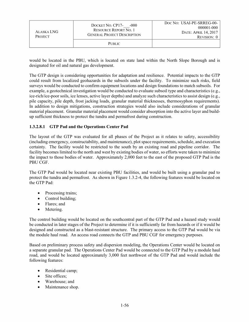
ALASKA LNG PROJECT
DOCKET NO. CP17-___-000 RESOURCE REPORT NO. 1
GENERAL PROJECT DESCRIPTION
DOC NO: USAI-PE-SRREG-00-000001-000
DATE: APRIL 14, 2017 REVISION: 0
PUBLIC
1-56
would be located in the PBU, which is located on state land within the North Slope Borough and is designated for oil and natural gas development.
The GTP design is considering opportunities for adaptation and resilience. Potential impacts to the GTP could result from localized geohazards in the subsoils under the facility. To minimize such risks, field surveys would be conducted to confirm equipment locations and design foundations to match subsoils. For example, a geotechnical investigation would be conducted to evaluate subsoil type and characteristics (e.g., ice-rich/ice-poor soils, ice lenses, active layer depths) and analyze such characteristics to assist design (e.g., pile capacity, pile depth, frost jacking loads, granular material thicknesses, thermosyphon requirements). In addition to design mitigations, construction strategies would also include considerations of granular material placement. Granular material placement would consider absorption into the active layer and build-up sufficient thickness to protect the tundra and permafrost during construction.
1.3.2.8.1 GTP Pad and the Operations Center Pad
The layout of the GTP was evaluated for all phases of the Project as it relates to safety, accessibility (including emergency, constructability, and maintenance), plot space requirements, schedule, and execution certainty. The facility would be restricted to the south by an existing road and pipeline corridor. The facility becomes limited to the north and west by existing bodies of water, so efforts were taken to minimize the impact to those bodies of water. Approximately 2,000 feet to the east of the proposed GTP Pad is the PBU CGF.
The GTP Pad would be located near existing PBU facilities, and would be built using a granular pad to protect the tundra and permafrost. As shown in Figure 1.3.2-4, the following features would be located on the GTP Pad:
Processing trains; Control building; Flares; and Metering.
The control building would be located on the southcentral part of the GTP Pad and a hazard study would be conducted in later stages of the Project to determine if it is sufficiently far from hazards or if it would be designed and constructed as a blast-resistant structure. The primary access to the GTP Pad would be via the module haul road. An access road connects the GTP and PBU CGF for emergency purposes.
Based on preliminary process safety and dispersion modeling, the Operations Center would be located on a separate granular pad. The Operations Center Pad would be connected to the GTP Pad by a module haul road, and would be located approximately 3,000 feet northwest of the GTP Pad and would include the following features:
Residential camp; Site offices; Warehouse; and Maintenance shop.
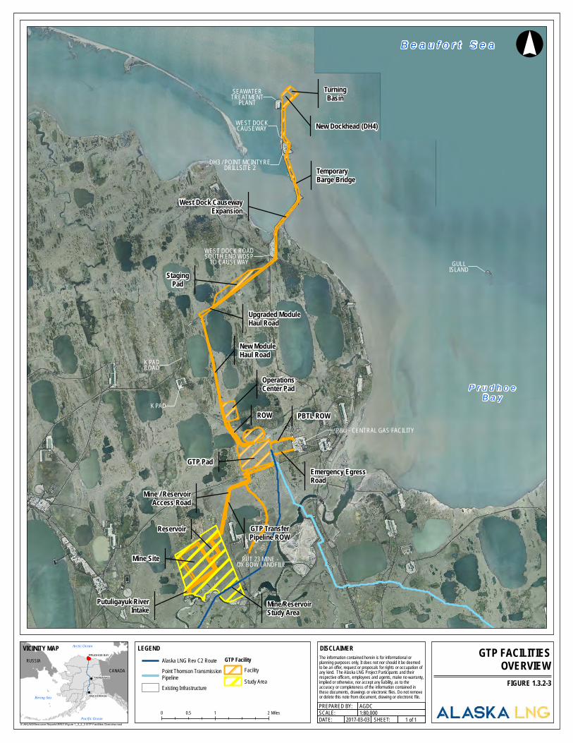
B e a u f o r t S e a
P r u d h o eB a y
West Dock CausewayExpansion
New Dockhead (DH4)
Upgraded ModuleHaul Road
OperationsCenter Pad
Emergency EgressRoad
GTP Pad
PBTL ROW
Mine/ReservoirStudy Area
Mine Site
Putuligayuk RiverIntake
TemporaryBarge Bridge
K PADROW
New ModuleHaul Road
Mine / ReservoirAccess Road
Reservoir GTP TransferPipeline ROW
StagingPad
TurningBasin
GULLISLAND
WEST DOCK ROADSOUTH END WDSPTO CAUSEWAY
SEAWATERTREATMENTPLANT
WEST DOCKCAUSEWAY
DH3 / POINT MCINTYREDRILLSITE 2
K PADROAD
PUT 23 MINE - OX BOW LANDFILL
LEGEND
0 1 20.5 Miles
GTP FACILITIESOVERVIEW
!°
SCALE:1 of 1
AGDCPREPARED BY:1:80,000
2017-03-03 SHEET:DATE:X:\AKLNG\Resource Reports\RR01\Figure 1_3_2_3 GTP Facilities Overview.mxd
Alaska LNG Rev C2 RoutePoint Thomson TransmissionPipelineExisting Infrastructure
GTP FacilityFacilityStudy Area FIGURE 1.3.2-3
!
!
!
CANADARUSSIA
Arctic Ocean
Pacific Ocean
Bering Sea ANCHORAGE
FAIRBANKS
PRUDHOE BAY
VICINITY MAP DISCLAIMERThe information contained herein is for informational or planning purposes only, It does not nor should it be deemed to be an offer, request or proposals for rights or occupation of any kind. The Alaska LNG Project Participants and their respective officers, employees and agents, make no warranty, implied or otherwise, nor accept any liability, as to the accuracy or completeness of the information contained inthese documents, drawings or electronic files. Do not removeor delete this note from document, drawing or electronic file.
PBU - CENTRAL GAS FACILITY
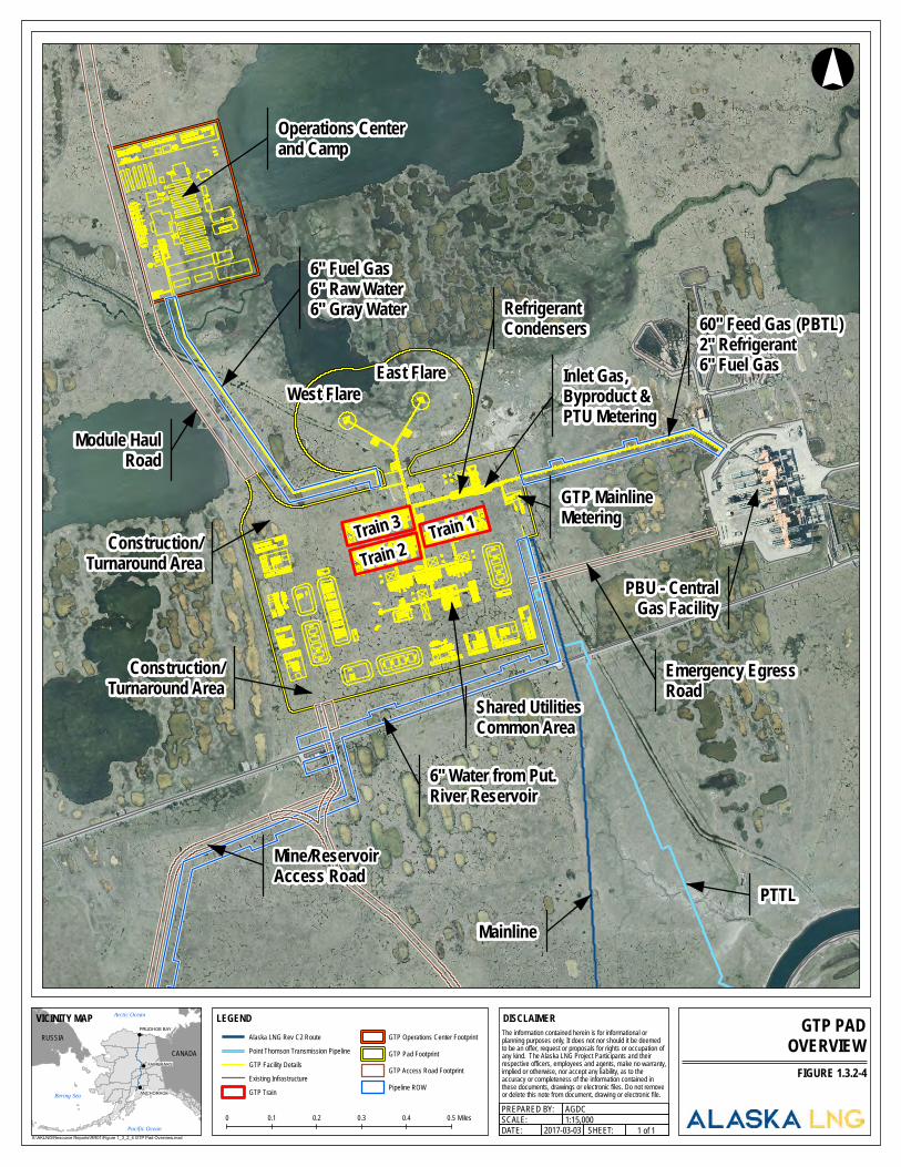
Construction/Turnaround Area
Module HaulRoad
PTTL
Train 3
Mainline
RefrigerantCondensers
Operations Centerand Camp
Shared UtilitiesCommon Area
6" Water from Put.River Reservoir
Train 2Train 1
Inlet Gas,Byproduct &PTU Metering
GTP MainlineMetering
PBU - CentralGas Facility
Mine/ReservoirAccess Road
West FlareEast Flare
60" Feed Gas (PBTL)2" Refrigerant6" Fuel Gas
6" Fuel Gas6" Raw Water6" Gray Water
Construction/Turnaround Area
Emergency EgressRoad
LEGEND
0 0.50.1 0.2 0.3 0.4 Miles
GTP PADOVERVIEW
!°
SCALE:1 of 1
AGDCPREPARED BY:1:15,000
2017-03-03 SHEET:DATE:X:\AKLNG\Resource Reports\RR01\Figure 1_3_2_4 GTP Pad Overview.mxd
FIGURE 1.3.2-4!
!
!
CANADARUSSIA
Arctic Ocean
Pacific Ocean
Bering Sea ANCHORAGE
FAIRBANKS
PRUDHOE BAY
VICINITY MAP DISCLAIMERThe information contained herein is for informational or planning purposes only, It does not nor should it be deemed to be an offer, request or proposals for rights or occupation of any kind. The Alaska LNG Project Participants and their respective officers, employees and agents, make no warranty, implied or otherwise, nor accept any liability, as to the accuracy or completeness of the information contained inthese documents, drawings or electronic files. Do not removeor delete this note from document, drawing or electronic file.
Alaska LNG Rev C2 RoutePoint Thomson Transmission PipelineGTP Facility DetailsExisting InfrastructureGTP Train
GTP Operations Center FootprintGTP Pad FootprintGTP Access Road FootprintPipeline ROW

ALASKA LNG PROJECT
DOCKET NO. CP17-___-000 RESOURCE REPORT NO. 1
GENERAL PROJECT DESCRIPTION
DOC NO: USAI-PE-SRREG-00-000001-000
DATE: APRIL 14, 2017 REVISION: 0
PUBLIC
1-59
The Operations Center Pad would be accessed from the module haul road connected to the GTP Pad.
1.3.2.8.2 Process Systems
The design of the GTP would have an average stream day inlet natural gas treating capacity of 3.7 BSCF/D and a 3.9 BSCF/D peak capacity23, and would be able to accommodate varying compositions of natural gas received from the PBU and PTU.
The design for the GTP consists of three parallel treatment trains, each sized to process roughly 1.3 BSCF/D of sour feed gas. The process removes the majority of carbon dioxide (CO2) and hydrogen sulfide (H2S) from the sour feed gas to the specification of the Liquefaction Facility, and most of the water (to a dew point specification for the Mainline). The treated gas then would be compressed in stages and routed to a natural gas chilling unit. The chilling unit uses a refrigerant to cool the gas. After refrigeration, the natural gas would be delivered to the Mainline at pressures up to 2,075 psig.
The GTP would include facilities in each treatment train to collect the CO2 and H2S removed from the natural gas. The CO2/H2S stream also would contain water and some hydrocarbons. The CO2/H2S stream from each train would be compressed and treated to remove water. The gaseous stream containing predominantly CO2 and some H2S from each train would be combined into a single stream (GTP Byproduct) that would be sent to the PBU.
As discussed in the following sections, the water removed from both the natural gas and the Byproduct streams would be injected at the GTP site through Class 1 industrial wells located on the GTP Pad.
A block diagram depicting the GTP treatment process is provided in Figure 1.3.2-5. Additional details of the process follow.
FIGURE 1.3.2-5 GTP Process Block Diagram of a GTP Train
23 Average stream day rate denotes the weighted 12-month average of monthly stream day rate values. Stream day rate represents the physical capacity of the facility at a particular ambient condition and does not account for planned or unplanned downtime (assume 100-percent uptime).

ALASKA LNG PROJECT
DOCKET NO. CP17-___-000 RESOURCE REPORT NO. 1
GENERAL PROJECT DESCRIPTION
DOC NO: USAI-PE-SRREG-00-000001-000
DATE: APRIL 14, 2017 REVISION: 0
PUBLIC
1-60
1.3.2.8.3 Inlet Facilities
The gas from the PBU would be metered for custody transfer at the PBU before entering the PBTL. Similarly, the feed gas from PTU would be custody transfer metered at the PTU before entering the PTTL.
The PTU gas would be sent through an inlet knock-out drum to allow any liquids that may form in the PTTL to drop out of the natural gas stream before entering the processing trains. The natural gas from PBU would be combined with the natural gas flow from PTU and then sent to the process trains. The inlet facilities would be located on the northeast corner of the GTP Pad (see Appendix B).
1.3.2.8.4 Acid Gas Removal Unit
There would be one acid gas removal unit (AGRU) per train. The AGRU would remove CO2 and H2S from the sour feed gas with the use of an amine solution and packed absorber tower commonly found in the natural gas treatment industry. The natural gas leaving the absorber tower would meet LNG specifications for CO2 and H2S but would also need to be treated by a gas dehydration unit to remove water to meet pipeline specification.
A regenerator, or second packed tower, would be used to release the CO2 and H2S from the amine solution. Once the CO2 and H2S are removed from the amine solution, the amine solution would be recirculated back to the absorber and the gaseous CO2/H2S stream would be compressed and dehydrated prior to return to PBU.
1.3.2.8.5 Treated Gas Dehydration Unit
There would be one treated gas dehydration unit system per train. The system would use glycol in a packed absorber tower to extract water from the natural gas stream. The dry natural gas stream would then flow to a treated gas compression system.
A regenerator, or second packed tower, would be used to release the water from the glycol solution using a stripping gas stream. Once the water has been removed, the glycol would be recirculated.
1.3.2.8.6 Treated Gas Compression
There would be one treated gas compression system per train. The purpose of the treated gas compression system would be to compress the dry natural gas to adequate pressure so that it enters the Mainline at the expected operating pressure. This would be done using natural gas turbine-driven compressors. GTP total treated gas compression power requirements would be approximately 298,000 ISO horsepower (combined for six units). Emissions would be controlled using dry low emissions combustors. The flue gas from the treated gas compression gas turbine drivers and from the CO2 compression gas turbine drivers would be used to heat the process heat medium, as discussed below.
The treated natural gas would flow from the treated gas compression system in each train to common treated natural gas chillers prior to introduction into the Mainline. During winter periods when the air temperature is sufficiently cold, adequate cooling can be provided by the compressor discharge coolers, and the treated natural gas chilling and refrigeration system would not need to operate.
ALASKA LNG PROJECT
DOCKET NO. CP17-___-000 RESOURCE REPORT NO. 1
GENERAL PROJECT DESCRIPTION
DOC NO: USAI-PE-SRREG-00-000001-000
DATE: APRIL 14, 2017 REVISION: 0
PUBLIC
1-61
1.3.2.8.7 Treated Gas Chilling and Refrigeration
Treated natural gas from the three trains would be combined and then cooled to 30 °F upon entering the Mainline, using a propane refrigerant for chilling. The treated natural gas would flow from the chillers through a metering station and into the Mainline.
The refrigeration system would have two compressors (totaling approximately 27,000 brake horsepower) to provide flexibility between the summer months, when both compressors are expected to operate, and winter months when either one or none of the compressors would be operating. For initial fill and makeup, liquid propane would be transferred to the GTP from the PBU.
The treated natural gas chillers and refrigeration system would be located on the northeast corner of the GTP pad (see Appendix B).
1.3.2.8.8 CO2 Compression and Dehydration
Each train would include one CO2 compression and one dehydration system. The CO2 compression system would compress the gaseous stream of predominately CO2 (with some H2S) released from the amine solution in four stages of compression. The first two stages would make up the low-pressure portion of the system and the last two stages would make up the high-pressure portion of the system. The low-pressure system would compress the gas to approximately 530 psig at which point the gas would be dehydrated by glycol in a contact tower. The process for dehydration would be similar to the treated gas dehydration unit described previously. Following dehydration, the CO2 would flow to the high-pressure portion of the system where the gas would be boosted to approximately 4,000 psig for return to PBU. Following compression, the gas from each train would be combined into a single stream and then flow through a meter to the PBU. CO2 compression at the GTP would be driven by natural gas turbines totaling approximately 205,000 ISO horsepower (combined for six units). Emissions would be controlled using dry low emissions combustors.
1.3.2.8.9 Utilities/Supporting Systems
Building Heat Medium System
One building heat medium system would be located in the common utility area. The purpose of the building heat medium system would be to provide heat for freeze protection for process buildings, storage tanks, liquid drums, and air coolers as required to prevent equipment damage (during both normal and off-case operations) and to facilitate equipment maintenance. It would use a mixture of water and glycol in a closed loop system as the heat medium, which is heated by fired heaters. This system would not heat the Operations Center buildings.
Cooling Medium Systems
Cooling medium systems would supply coolant to major GTP machinery (e.g., large compressors, etc.), pumps that require seal cooling, and some process heat exchangers. The cooling medium would be cooled using an air cooler. There would be one cooling medium system in each of the three trains. Additionally, air compressors, refrigeration compressors, and power generators would have their own cooling systems.
ALASKA LNG PROJECT
DOCKET NO. CP17-___-000 RESOURCE REPORT NO. 1
GENERAL PROJECT DESCRIPTION
DOC NO: USAI-PE-SRREG-00-000001-000
DATE: APRIL 14, 2017 REVISION: 0
PUBLIC
1-62
Process Heat Medium Systems
The purpose of the process heat medium systems would be to provide process heating to the AGRU reboilers. The system would use pressurized water as the heat medium, which is heated in the waste heat recovery Units (WHRUs) by the exhaust from the gas turbines on the treated gas compressors and the CO2 compressors in each train. Additional process heating requirements would be supplied by gas-fired duct burners (supplemental firing) within each of the WHRUs. The stacks associated with the WHRUs would be approximately 240 feet tall and are likely to be the tallest structures at the GTP.
Electrical Power Generation System
The essential power generation for the GTP and GTP camp during construction would be supplied by a diesel generator located on the GTP Pad. An emergency diesel generator, located at the GTP Operations Center, would provide backup power for stairwell pressurization fans at the GTP Operations Center. Another emergency diesel generator would be provided at the Communications building to provide backup power.
The main power generation for the operation of the facility would be through six power generator natural gas turbines. The turbines would be located on the GTP Pad totaling approximately 267,000 to 299,000 horsepower. Emissions would be controlled using dry low emissions combustors. Alternatives for GTP power generation are provided on Resource Report 10, Section 10.5.5.2
Fuel Gas System
The fuel gas system supplies gas to the Operations Center via transfer line from the PBU CGF. The fuel gas system would supply fuel gas to the gas turbines, supplemental firing for WHRUs, fired heaters, and flare system purges. Fuel gas would also be used as blanketing gas for a variety of equipment that either requires a higher pressure or a lower oxygen content than the nitrogen blanketing gas.
Flare System
Four flare systems would be provided for the GTP: HP hydrocarbon flare, LP hydrocarbon flare, HP CO2 flare, and LP CO2 flare. The flares are located to minimize radiant heat impacts on the facilities and to minimize downwind personnel exposure resulting from the prevailing wind direction.
Separate HP and LP hydrocarbon flares enable more efficient design by allowing low pressure gas to enter its own flare system with no interference from high pressure gas sources. HP and LP CO2 systems would be segregated to keep water out of the high-pressure CO2 system.
The design of the GTP facilities would not generate any continuous process or utility flow sources to flare or vent, except from limited pilot/purge streams. The flare system is for startup, emergency, pre-commissioning, commissioning, shutdown, or upset conditions. In general, protection systems would be designed to minimize potential flaring/venting flow rates to reduce impacts.

ALASKA LNG PROJECT
DOCKET NO. CP17-___-000 RESOURCE REPORT NO. 1
GENERAL PROJECT DESCRIPTION
DOC NO: USAI-PE-SRREG-00-000001-000
DATE: APRIL 14, 2017 REVISION: 0
PUBLIC
1-63
Drain Systems and Injection Wells
Both open and closed drains would be provided for each train and for the common areas. The open drain system drains would capture utility station spent water (e.g., wash water) as well as any leaks and spills within the modules. Open drain liquids would be collected via sloped floors and drain trenches to sumps. The sump liquids would be pumped to the closed drain collection system.
The closed drain system collects liquids and solvents from process equipment and piping that is generated during normal operation and drained from the system during maintenance activities. The closed drain system would be separated into three separate closed drain systems to facilitate recovery and reuse of solvents: (1) process closed drain system for process fluids such as hydrocarbons and water; (2) triethylene glycol drain system for draining the treated gas dehydration and CO2 dehydrations systems; and (3) the AGRU solvent drain system for draining amine from the AGRU system.
The liquids from the closed drain system (approximately 190 gallons per minute) would be piped to one of two Underground Injection Control (UIC) Class 1 industrial injection wells located on the GTP pad for subsurface disposal. The wells would be approximately 6,000 to 7,000 feet of vertical depth. Design provisions would be made such that fluids from the open drain, triethylene glycol drain, and AGRU solvent drain can be injected into these wells through the process drain system.
Waste streams from each train and the common area would be collected in the common closed drain collection drum. The drum would receive continuous flow from the following:
Grey water from wastewater treatment plant (approximately 59 percent of continuous flow);
Reverse osmosis reject water (approximately 8.5 percent of continuous flow);
Backwash water from potable water treatment (approximately 6.5 percent of continuous flow); and
Process water from the three gas processing trains (approximately 26 percent of continuous flow). This stream is greater than 99 percent water with trace quantities (parts per million) of hydrocarbons, CO2, H2S, and tri-ethylene glycol.
The common closed drain collection drum would also be connected to other process waste streams that have intermittent flow. These waste streams would contain substances intrinsically derived from operations associated with the production of natural gas including oily water, sour water, amine, triethylene glycol, hydrocarbons, and trace amounts of CO2 and H2S (i.e., Resource Conservation and Recovery Act [RCRA] exempt). Liquid waste from the open drain system would be delivered to the common closed drain collection drum. Liquid waste from the common closed drain collection drum would be injected into the disposal well(s). Accounting for these estimated intermittent flows, the liquid waste would be injected at a rate up to 225 gallons per minute and pressure up to 2,000 psig. Although the injection wells are configured to be spares to each other, both would normally operate. To prevent freezing in the wells, diesel, a mixture of methanol/water or other fluid that is miscible with disposal fluids may be injected into the inactive well during winter.
ALASKA LNG PROJECT
DOCKET NO. CP17-___-000 RESOURCE REPORT NO. 1
GENERAL PROJECT DESCRIPTION
DOC NO: USAI-PE-SRREG-00-000001-000
DATE: APRIL 14, 2017 REVISION: 0
PUBLIC
1-64
The injection wells would be permitted under EPA jurisdiction as Class I industrial injection wells for injection of non-hazardous and RCRA-exempt liquid waste streams.
Water Systems
The GTP water systems would provide water of the quality required by various users in the GTP and operations camp, including process makeup requirements, firewater, and potable water. The Putuligayuk River would be the source of freshwater for the GTP. Water from the river would be used to fill a reservoir during the spring breakup period that would be used to ensure year-round water supply to the facility. Additional details of the water reservoir are provided in the GTP Associated Infrastructure Section 1.3.2.8.11.
Process water would be required for makeup to the AGRU, the process heat medium system, and for turbine wash water. A portion of the incoming raw water would be treated through a packaged water treatment unit for process water. The process water treatment system would be located in the common utilities area. Water treatment will be by reverse osmosis, with the reject water sent through the closed drain system to the injection wells.
A portion of the raw water would also be treated to meet drinking water standards in a packaged potable water treatment system located at the GTP and at the camp. The potable water systems would supply water to the control room humidifier, eyewash stations, safety showers, and restroom facilities at both the GTP and operations camp. The potable water treatment would be located in the common utilities area at the GTP pad and on the Operations Center Pad. The backwash from the potable water system would also be sent through the closed drain system to the injection wells.
Methanol System
Methanol would be used for hydrate inhibition or for hydrate mitigation where required (e.g., upstream of aerial coolers in wet gas service in low ambient temperatures conditions). The use of methanol would be a reactive measure; no storage, transfer, or injection equipment would be permanently installed as part of the GTP process. It would be a portable system deployed when required to mitigate hydrate formation.
Lighting
GTP module, tower, and stack lighting would meet regulatory requirements, codes, and standards for lighting for overall site operations/maintenance, safety, and security. In addition, lighting would be designed to address guidance provided by the USFWS as practicable to reduce potential impacts on birds and other wildlife.
To the extent practical, lighting design for the GTP would minimize projection outward to avoid impacts to wildlife. Final location, number of lights, and shielding installation would be determined in future stages of engineering design.
Additional details on lighting are provided in the Lighting Plan in Appendix O of Resource Report No. 8.

ALASKA LNG PROJECT
DOCKET NO. CP17-___-000 RESOURCE REPORT NO. 1
GENERAL PROJECT DESCRIPTION
DOC NO: USAI-PE-SRREG-00-000001-000
DATE: APRIL 14, 2017 REVISION: 0
PUBLIC
1-65
Air Systems
The GTP would include an air system that would be used to supply compressed, dry air to the following systems:
Instrument air; Utility or service air; Breathing air; and Nitrogen Generation System.
The air compressors and dryers would be located in the common utilities area and air would be distributed to the process areas as required. A separate compressed air system would be supplied at the operations camp for equipment maintenance.
Nitrogen System
Nitrogen would be used continuously at the GTP for some tank and vessel blanketing (where oxygen in the blanket gas can be tolerated), small vessel purges, and buffer gas for the dry compressor seals and intermittently at utility stations and to purge vessels for maintenance. The nitrogen for continuous use would be produced from compressed, dried air via separation from oxygen using a nitrogen membrane package or supplied by nitrogen bottle. Intermittent users (and peak continuous loads) would be supplied from liquid nitrogen trucked to the facility. The nitrogen system would be located in the common utilities area of the plant.
Diesel and Gasoline Fuel System
Arctic grade ultra-low sulfur diesel would be trucked to the GTP plant and stored for use on the GTP pad and Operations Center pad. The diesel fuel storage tank on the GTP pad would have a nominal capacity of 19,500 gallons and be sized to hold two weeks of diesel for the emergency and essential generators, diesel firewater pumps, and diesel fuel for service vehicles. The majority of this volume would be for vehicle usage. Usage by the emergency and essential diesel generators and firewater system would be for emergency and testing purposes.
The diesel-driven firewater pumps, communication tower, and the camp emergency diesel generators would be located at the operations camp. Day tanks would be supplied directly via truck delivery to the operations camp. A list and description of the fuel systems equipment is provided in Table 1.3.2-12.
TABLE 1.3.2-12
Estimated GTP Fuel Systems Storage Size Equipment Gallons Diesel Fuel Storage Tank 19,500 Diesel Fueling Station Storage Drum 450 Dormitory Emergency Diesel Generator Day Storage 200 Essential Diesel Generator Day Storage 3,600 Firewater Diesel Day Storage Drum (each – 3 drums total) 350

ALASKA LNG PROJECT
DOCKET NO. CP17-___-000 RESOURCE REPORT NO. 1
GENERAL PROJECT DESCRIPTION
DOC NO: USAI-PE-SRREG-00-000001-000
DATE: APRIL 14, 2017 REVISION: 0
PUBLIC
1-66
TABLE 1.3.2-12
Estimated GTP Fuel Systems Storage Size Equipment Gallons Communication Tower Diesel Generator 24 hours of storage located in the base of the generator
(gallons—TBD) Gasoline Storage 10,000
Gasoline would be trucked to the GTP plant and stored for use at the GTP Operations Center. The gasoline storage tank would have a nominal capacity of approximately 10,000 gallons and would supply gasoline for service vehicles.
The fuel systems would be designed and operated in compliance with federal and state regulatory requirements and the SPCC Plan (Appendix M of Resource Report No. 2).
Chemical Storage
Storage for process chemicals would be provided on the GTP Pad. The chemical storage tanks would include storage for amine (130,000 gallons), triethylene glycol (26,500 gallons), and diesel (discussed previously). There would also be an additional empty tank with a capacity of 962,000 gallons to hold the amine from one train if it were to be taken out of service. A hydrocarbon holding tank would also be provided at the GTP Operations Center. The hydrocarbon holding tank is designed to hold recyclable waste diesel, glycol, solvents, miscellaneous fuels, and lubricants. This tank would be emptied using a vacuum truck as needed and either recycled or transported to an existing approved handling facility. Sizing for the hydrocarbon holding tank would be confirmed during later stages of the Project design.
The chemical storage area would be designed and operated in compliance with ADEC and EPA requirements. The Project-specific SPCC Plan (Appendix M of Resource Report No. 2) would address the measures described in Section 1.3.2.8.9.13.
Telecommunications Tower
The GTP communication tower would be located at the Operations Camp and would be approximately 150 feet tall. The required height for the GTP tower would be determined in later stages of the Project design. The tower would require lights for aviation safety, but would be designed to address guidance provided by the USFWS as practicable to reduce potential impacts on birds and other wildlife.
1.3.2.8.10 Associated Transfer Pipelines
The transfer pipelines that would deliver feed gas to the GTP are described in Section 1.3.2.2 and 1.3.2.3. Several other transfer pipelines would be necessary to supply the GTP, including the following:
Fuel gas pipeline (approximately 2 miles of 6-inch pipe) delivering fuel gas from the PBU CGF to the GTP and GTP Operations Camp;

ALASKA LNG PROJECT
DOCKET NO. CP17-___-000 RESOURCE REPORT NO. 1
GENERAL PROJECT DESCRIPTION
DOC NO: USAI-PE-SRREG-00-000001-000
DATE: APRIL 14, 2017 REVISION: 0
PUBLIC
1-67
Propane pipeline (approximately 1 mile of 2-inch pipe) taking propane from the PBU CGF to the GTP for use in the GTP refrigeration system;
Putuligayuk River pipeline (approximately 1 mile of 14-inch pipe) delivering water from the Putuligayuk River to the reservoir (described in Section 1.3.2.8.11.2, Water Reservoir); and
Supply water pipeline (approximately 5 miles of 6-inch pipe) taking raw water from the reservoir to the GTP and GTP operations camp (described in Section 1.3.2.8.11.2, Water Reservoir).
The PBU CGF to GTP pipelines would be supported on VSMs in a new elevated pipeline system for much of the route between the PBU CGF and GTP (see typical aboveground pipe rack arrangement in Appendix E and a description of VSMs in Section 1.3.2.2). The PBTL, propane pipeline, and fuel gas pipeline would share the same route from the general area of the northwest corner of the PBU CGF to the general area of the northeast corner of the GTP.
1.3.2.8.11 GTP Associated Infrastructure
To operate the GTP facility, additional facilities would be built and maintained on site. A description of these additional facilities and systems is provided as follows.
Permanent Operations Camp
When construction is complete, the onsite construction camp would remain as a permanent operations and turnaround accommodation facility. On a normal operating basis, the operations camp facility would accommodate approximately 125 personnel. During maintenance turnaround activities, the operations camp facility would accommodate a maximum capacity of up to 1,680 beds if required. The permanent camp would include offices, dormitories, kitchen, dining, recreation, and medical and aid facilities.
Water Reservoir
The GTP water systems would provide water to various users in the GTP and operations camp including process makeup requirements, firewater, and potable water (see Water Use Plan located in Resource Report No. 2, Appendix K). A planned water reservoir would likely not be available early enough to provide a portion of the construction water needs. Water supply to the GTP and Integrated Construction and Operations camp would originate from the Putuligayuk River. Due to the low flow in the winter and presence of fish within the river, year-round withdrawal of sufficiently large quantities is unlikely. To ensure year-round water supply, water from the river would be used to fill a reservoir during spring breakup when there is sufficient water runoff.
The exact location and layout of the reservoir site has not been finalized, but it is planned to be located within the study area identified on Figure 1.3.2-3. The preliminary reservoir design includes a footprint of approximately 35 acres with a depth in range of 35 to 60 feet. The reservoir is designed to provide year-round supply and is expected to form a surface ice pack of approximately 8 feet, which is not included in the net available capacity. Pump requirements, silt and salinity layers, side slope, ramp design, and other factors would affect the net available capacity in comparison to the total volume of the reservoir. The preliminary estimate for available capacity is 250 million gallons, a two-year water supply for the GTP that

ALASKA LNG PROJECT
DOCKET NO. CP17-___-000 RESOURCE REPORT NO. 1
GENERAL PROJECT DESCRIPTION
DOC NO: USAI-PE-SRREG-00-000001-000
DATE: APRIL 14, 2017 REVISION: 0
PUBLIC
1-68
would support process and potable water demands. The water intake structure would be located on the Putuligayuk River and draw water during spring breakup at acceptable flow rates through protective fish screens (3/32 inches maximum opening size).
The preliminary design of the GTP water system includes the following pump station modules:
The Putuligayuk River Water Pump Module would pump water from the Putuligayuk River into the reservoir and include the following equipment:
○ The Putuligayuk River pipeline with filter (approximately 1 mile of 14-inch pipe) would draw water up out of the Putuligayuk River to accommodate single- and dual-pump operation. The river intake structures would comply with Alaska Department of Fish and Game (ADF&G) regulations and would be designed to minimize adverse environmental impact;
○ Two motor-driven pumps would be included with normally one pump in operation (approximately 2,500 gallons per minute), and the other as a standby spare; or if a faster reservoir fill-rate is desired (approximately 5,000 gallons per minute), they would be run in parallel;
○ Pump strainers (one for each pump) would remove larger solids from the water stream (primarily to protect the pumps and the downstream flow meter); and
○ Flow meters would be downstream of the pumps and would be sized and spanned to cover single flow from each pump; these meters would need to show instantaneous flow readings, as well show the total volume taken up from the river and transferred to the reservoir.
The Reservoir Water Pump Module would pump water from the reservoir to the GTP and would include the following equipment:
○ The supply water pipeline with filter (approximately 4 miles of 6-inch pipe) would draw water up from the reservoir. The water is anticipated to be about 35 °F, so in the winter season heat-trace is important to protect against freeze-up. The water pipeline travels for most of its route to the GTP using typical pipe supports. At the general area of the south-west GTP Pad, it runs parallel to the existing PBU Gas Handling Expansion pipeline, and travels north along the east side of the GTP Pad, where it ties into the onsite GTP piping proper;
○ Two water supply pumps would take water up and out of the reservoir. The design is for one pump to run, while the other would be available as a standby spare; and
○ Two water delivery pumps would deliver the water to the GTP. The design is for one pump to run, while the other would be available as a standby spare.
Electrical equipment, metering equipment, and air handling equipment would also be housed at the pump stations.

ALASKA LNG PROJECT
DOCKET NO. CP17-___-000 RESOURCE REPORT NO. 1
GENERAL PROJECT DESCRIPTION
DOC NO: USAI-PE-SRREG-00-000001-000
DATE: APRIL 14, 2017 REVISION: 0
PUBLIC
1-69
An integrated granular material/water use system where material excavated for development of the reservoir would be used for project infrastructure such as granular pads and roads. The permits and authorizations required to complete the water reservoir are described in Appendix C (Federal, State, and Local Authorizations Anticipated for the Project).
1.3.2.8.12 Facilities Associated with the Construction of the GTP
West Dock Modifications
The West Dock Causeway, which runs approximately 2.5 miles from the shoreline to the west end of Prudhoe Bay, is a solid fill granular material structure that was constructed in three segments between 1974 and 1981. The first segment is approximately 4,000 feet long extending from land to West Dock Dock Head (DH) 2. During the summer of 1975, the second segment was constructed and extended the causeway approximately 5,000 feet to Dock Head 3 (DH 3). In 1981, a third extension elongated the causeway approximately 5,000 additional feet to accommodate construction of the seawater treatment plant (STP). Due to concerns that the causeway could potentially affect coastal currents and marine resources, a 650-foot channel/breach located between DH 2 and DH 3 was constructed between 1995 and 1996.
GTP construction requires large modules that can only be transported to the North Slope by sealift. A new dock near the STP, to be named DH 4, would be used to offload modules arriving by sealift, and a new staging area would be located south of the existing West Dock staging area. The dock face would be approximately 1,000 feet wide and elevated approximately 8 feet above sea level. The five or more new berths would be dedicated to Project activities. The new dock would provide a working area of approximately 31 acres (see Appendix B). Further information concerning modifications to West Dock is provided Report 2, Section 2.3.8.2.6.8 (West Dock Modifications) and Resource Report 10, Section 10.5.7.1 (West Dock).
All cargo barges would be grounded for the modules offloaded at DH 4. The grounding pad for the barges would be prepared in advance of each sealift.
Module Staging Area
A new module staging area (approximately 86 acres) would be constructed for placement of the modules immediately following offload. The staging area would be an extension off the northwest side of the K Pad road just south of the existing West Dock staging area (see Figure 1.3.2-3). Following construction, the module staging area would remain in place for future equipment deliveries, turnarounds, and decommissioning and dismantling of the facility.
Over-summering of ice work pads for module storage and staging is not practical from a construction standpoint because the modules would be delivered in the summer months, requiring an ice work pad to be made the previous winter and maintained until the delivery of the module. Previous over-summering of ice pads on the North Slope occurred when ambient temperatures trended cooler. The modules for the GTP are very heavy (9,400 tons), which could be problematic with ice pads.

ALASKA LNG PROJECT
DOCKET NO. CP17-___-000 RESOURCE REPORT NO. 1
GENERAL PROJECT DESCRIPTION
DOC NO: USAI-PE-SRREG-00-000001-000
DATE: APRIL 14, 2017 REVISION: 0
PUBLIC
1-70
Camps
Pioneer Camp
A Pioneer Camp would be established to support development of construction infrastructure during GTP construction, including granular mine operations and construction of access roads, granular pads, reservoir, VSMs, and pipelines. The camp would continue to support the Project after the onsite construction/operations camp becomes available. The Pioneer Camp would be located on an existing granular pad in the PBU or in the Deadhorse area to reduce environmental impact and resource requirements. The Pioneer Camp would be sized to accommodate approximately 600 personnel. The Pioneer Camp would be stablished in the winter of 2019–2020.
Construction and Operating Camps
An onsite Integrated Construction and Operations Camp would be constructed to support Project construction. Following construction of the Operations Center granular pad and VSM piles to support the camp structures, the accommodations blocks and common areas of the construction camp would be completed. The onsite Construction and Operations Camp would be sized to accommodate up to 1,680 personnel to manage peak staffing loads during construction and turnarounds and 125 personnel under normal circumstances.
The Integrated Construction and Operations Camp would be used during construction, commissioning, and startup of the facility. As noted, once construction, commissioning, and startup of the facility are complete, the Construction and Operations Camp would remain as a permanent operations and turnaround facility.
Electrical Power Generation
Low-voltage, temporary power generators, and mobile power generators would be used during plant construction, before the first sealift brings the permanent site generators and utilities. Alternatives for GTP power generation are provided on Resource Report 10, Section 10.5.5.2.
Water System
Water for construction would be brought in via trucks and stored on site until the water reservoir and pumping stations necessary to support the construction and operations camp are established. Potential alternative water sources in the vicinity of the GTP are discussed in Resource Report No. 10, Section 10.5.4.3. Estimated water use for GTP is included in the Project Water Use Plan located in Resource Report No. 2, Appendix K.
Waste and wastewater treatment for GTP construction and operations is provided in Section 1.3.8.3 of this Resource Report.
Ultra-low Sulfur Diesel Fuel System
Approximately 42 million gallons of Arctic-grade, ultra-low sulfur diesel fuel would be required for the construction of the GTP, not including marine operations, over an eight-year period. Fuel would be

ALASKA LNG PROJECT
DOCKET NO. CP17-___-000 RESOURCE REPORT NO. 1
GENERAL PROJECT DESCRIPTION
DOC NO: USAI-PE-SRREG-00-000001-000
DATE: APRIL 14, 2017 REVISION: 0
PUBLIC
1-71
delivered by barge and/or truck over the construction period. The average usage for land-based equipment for the duration of the Project would be approximately 500,000 gallons per month.
Construction diesel storage of approximately one to three weeks’ demand would be located on the Operations Center Pad to provide diesel fuel for vehicles and equipment. The size and number of tanks has not yet been determined, but they would be located in a fully lined berm system. The fuel storage area would be designed and operated in compliance with ADEC and EPA requirements, and the Project’s SPCC
Plan (Appendix M of Resource Report No. 2).
Bulk storage of diesel fuel would be in the PBU or in the Deadhorse area to supply peak demand and filling operations of the onsite storage.
1.3.3 Project Meter Stations
Meter stations would be installed to measure gas volume and composition during custody transfer from one entity to another and for verification measurement of natural gas at pipeline design boundaries (likely corresponds to fence line). Only meter stations that would transfer gas custody among the major Project components and between Project components and third-party facilities are included in this section. The design includes four meter stations associated with the delivery of natural gas to the Liquefaction Facility:
Prudhoe Bay Unit Meter Station, collocated with the PBU CGF to provide custody transfer measurements of natural gas entering the PBTL from the PBU;
Point Thomson Unit Meter Station, collocated within PTU to provide custody transfer measurements of natural gas entering PTTL from the PTU;
GTP/Mainline Meter Station, collocated within the GTP to measure natural gas entering the Mainline from the GTP; and
Nikiski Meter Station, collocated within the Liquefaction Facility to measure natural gas entering the Liquefaction Facility from the Mainline.
The design includes several interface meters related to GTP and PBU operations. The interface meters would be used for a variety of purposes including material balances and accounting:
PTU Transmission Line Meter, GTP Inlet: Process meter to measure feed gas transferred from PTU to the GTP;
GTP Byproduct Return Meter: Process meter to measure Byproduct transferred from the GTP facility to PBU;
GTP Fuel Buyback Meter: Process meter to measure treated fuel gas from the Mainline returned to the GTP for fuel use;
Propane Makeup Meter: Custody transfer meter located at PBU to measure propane transferred from PBU to the GTP; and

ALASKA LNG PROJECT
DOCKET NO. CP17-___-000 RESOURCE REPORT NO. 1
GENERAL PROJECT DESCRIPTION
DOC NO: USAI-PE-SRREG-00-000001-000
DATE: APRIL 14, 2017 REVISION: 0
PUBLIC
1-72
PBU Fuel Gas Meter: Custody transfer meter located at PBU to measure fuel gas transferred from PBU to the GTP.
Each meter station would typically include:
Isolation valves; Above-grade piping; Instrument building; A meter-run building; A gas chromatograph; and Flow-metering.
Meter station buildings would be elevated on pilings as required to mitigate heat transfer to the underlying permafrost.
Each meter run consists of the straight length section of piping and equipment required for each ultrasonic meter. The piping “run” is specially fabricated to be smooth and free of internal obstructions so that the gas flow is uniform and an accurate measurement can be taken. There would typically be three to four meter runs at each meter station so that equipment can be isolated for maintenance and calibration, while maintaining system operation. Each piping meter run would include straightening vanes, a multipath ultrasonic flow meter, a single-path ultrasonic flow meter, gas-sampling port, and isolation valves.
1.3.4 Project Access Roads
Access roads would be required during construction of the pipelines and aboveground facilities to transport equipment, material, pipe, and personnel to the ROW, compressor stations, material sites, and other locations (Appendix F). These access roads include existing public roads, existing non-public roads, newly built access roads, and shoo-flies. There are no access roads required for the PBTL and Byproducts pipelines since they will be accessed through the GTP and PBU CGF.
For public roads that would be used during construction of the Project, the potential need for road improvements would be evaluated. Many of the existing non-public roads (e.g., PBU and TAPS access roads), including those that may not currently be used, may require modifications, as well as agreements with the third parties for use, to accommodate large and heavy construction equipment and material.
If existing roads are not readily available, or do not provide adequate access, the Project would require new temporary or permanent access roads using available native material, imported granular material, or temporary use of snow/ice, depending on the intended traffic load, duration, and timing of use. Construction of some new permanent roads to access compressor stations and the heater station would be needed. Permanent or temporary bridges would be constructed, if needed, to cross waterbodies, depending on water levels. A typical cross section for Access Roads is shown on Appendix E.
1.3.4.1 Liquefaction Facility Access Roads
During the operating phase, the main entry to the Liquefaction Facility would be at the southern fence line in proximity to where the Kenai Spur Highway would be rerouted around the LNG Plant (see Section

ALASKA LNG PROJECT
DOCKET NO. CP17-___-000 RESOURCE REPORT NO. 1
GENERAL PROJECT DESCRIPTION
DOC NO: USAI-PE-SRREG-00-000001-000
DATE: APRIL 14, 2017 REVISION: 0
PUBLIC
1-73
1.3.9.4). There would be a secondary entrance to the plant for contractors and large material deliveries from the north, again in the proximity of the Kenai Spur Highway reroute. The finish of the in-plant roads would be a mix of concrete, asphalt, and compacted granular material based on road use classification. The final elevation of the permanent road system would be designed for compatibility with the site stormwater system.
During construction, in-plant road networks would change to address site activities: site preparation, equipment storage and laydown, equipment and module setting, final grading, and transition to the final in-plant road system. The road surface during construction would be stabilized native soils or compacted granular material and the roads would be periodically graded and compacted to maintain trafficability. The heavy haul road from the temporary MOF would be coarse hot-mix asphalt over a crushed aggregate base to withstand the heavy loads and provide a weather-resistant surface with good friction qualities.
1.3.4.2 Pipeline Access Roads
Access roads and shoo-flies24 are used to transport equipment, material, pipe, and personnel to the Project area, some of which may be retained for permanent use during operations (see Appendix F for the Mainline and PTTL). The Project’s representatives would work with landowners to determine the requirements for reclaiming the land and/or leaving the access roads in place after construction.
No access roads are planned for the PBTL for construction or operations at this time.
1.3.4.3 GTP Access Roads
An access road and an emergency egress road to the GTP would be required, with a third service road connecting the GTP to the water reservoir and granular material mine (see Figures 1.3.2-3 and 1.3.2-4). Existing roads would be used to the extent practicable for the GTP access road. The emergency egress road and service road would be new. In addition, a new service road is proposed that would connect the GTP to the southern PBU road network (e.g., Spine Road) and provide greater access to the GTP mine.
An emergency egress road to the GTP site located on the east side of the GTP pad would connect to the existing PBU CGF facility. This road would have a top width of 40–50 feet and be of limited use. It would provide additional egress from the GTP Pad while also providing for an additional access point for emergency support services via the existing PBU CGF. This configuration provides two safe egress points that are cross-wind of the GTP facility.
A third access road would connect the GTP to the water reservoir and the granular material mine. The road would be approximately 3.4 miles long and have a top width of 50 to 60 feet. In addition, a road from this gravel mine access road (southern access road) would connect to the drill site 15 access road to connect the GTP to the southern infrastructure and provide another egress route.
The main access road to the facility would double as the module haul and return roads, entering from the northwest corner of the GTP Pad. The existing portions (i.e., West Dock Causeway and K Pad Road) of
24 Shoo-flies are temporary roads bypassing constrained sections of the construction ROW.

ALASKA LNG PROJECT
DOCKET NO. CP17-___-000 RESOURCE REPORT NO. 1
GENERAL PROJECT DESCRIPTION
DOC NO: USAI-PE-SRREG-00-000001-000
DATE: APRIL 14, 2017 REVISION: 0
PUBLIC
1-74
the main access road would be upgraded to support module hauls, and turn-outs provided to facilitate two-way traffic during construction as modules are being transported to the site. Improvements to the existing roads include using granular material to widen the existing causeway and K Pad access road from the DH 4 dock site to a location approximately 6,000 feet northeast of the K Pad. The improvements are:
A parallel 100–125-foot-wide and approximately 5,000-foot-long causeway would be built on the east side from DH 3 to DH 4 because the existing causeway leading up to the STP is at a much higher elevation;
The other two existing segments of West Dock Causeway would be upgraded to a width of approximately 100–125 feet from the current width ranging from approximately 40 to 80 feet from the dock pad to landfall, an approximate distance of 4,500 feet from DH 3 to DH 2 and 3,800 feet from DH 2 to land. Widening would be conducted on the east side (within the shallow water area) because there is a pipeline along the west side; and
The K Pad access road would be upgraded to a width of 100 feet from its current width of 40 feet. Widening would be done to the northern side since there is a pipeline along the southern shoulder.
A new section of module haul road would be constructed from the existing K Pad access road.
1.3.4.3.1 Barge Bridge
The existing bridge across the 650-foot channel/breach located between DH 2 and DH 3 is limited to single-lane, light vehicle traffic at a width of 20 feet, and an approximate load limit of 100 tons. A bridge with capacity to support the modules would be required for a successful sealift. A temporary barge bridge consisting of two barges ballasted to the sea floor would be used to span the gap. The barges would be placed at the beginning of the open-water season prior to each sealift.
The barge bridge would provide up to three areas for fish passage, if required during the proposed time of use (e.g., between the barges and between each barge and the adjacent bulkhead). Pre-work would be performed a year before the first sealift to prepare the seafloor and install breasting-dolphins for the barge bridge support. The surface would be prepared using minimal fill and placement of gabion mattresses to prevent scour. The barges would be removed at the end of each sealift and the surface would need to be prepared again prior to each sealift year. As additional data is acquired and further guidance received on fish passage requirements, the barge bridge surface, structures, and mooring systems would be re-analyzed and may require updates.
1.3.4.3.2 GTP Ice Roads
The access roads that are planned to be constructed of granular material would accommodate use year round. There are also onshore ice roads planned for construction of GTP infrastructure including winter construction of the pipelines/transfer lines.
Ice roads would be needed in the first few winters of construction to connect the granular material site to the GTP Pad site and to connect water sources to the GTP Pad site. Ice roads would also be required during

ALASKA LNG PROJECT
DOCKET NO. CP17-___-000 RESOURCE REPORT NO. 1
GENERAL PROJECT DESCRIPTION
DOC NO: USAI-PE-SRREG-00-000001-000
DATE: APRIL 14, 2017 REVISION: 0
PUBLIC
1-75
construction of the water pipeline, pipelines on VSMs between the GTP and PBU CGF, and for other utility construction. Estimated volumes of water is provided in Table 1.3.2-13 and potential sources of water for ice road construction is provided in the Water Use Plan located in Resource Report No. 2, Appendix K.
GTP Pipeline Construction ROW Ice Roads
Table 1.3.2-13 summarizes the various construction ROW ice roads and pads needed to construct the pipelines associated with GTP. Ice roads used as construction ROW for transfer pipelines between the PBU and GTP (including PBTL) would be approximately 120 feet wide, with additional space as necessary for laydown and expansion loops. The water/ice chips requirements are estimated for the total expected length of the ROW. It is planned that each ROW section listed would take one winter season to complete, however it has not yet been determined if they would all occur over the same season or over multiple seasons. The mine site and reservoir perimeter roads would be rebuilt each year during construction/mining operations. Ice road corridors would be reused to the extent practicable, while avoiding any tundra damage.
Tundra impacts would be minimized by adhering to standard regulatory conditions for tundra travel, as described below.
Per Title 11 Alaska Administrative Code Section 96.014(b)(1), a permit from the DNR, DMLW is required for motorized vehicle use on the North Slope area for all state land in townships within the Umiat Meridian. The DMLW monitors snow depths and soil temperatures throughout the winter season to determine when to open the tundra to general off-road travel. The tundra is opened to off-road travel in the Coastal Area of the North Slope when the soil temperature at a depth of 12 inches reaches -5 degrees Celsius and when there is a minimum of six inches of snow on the ground. Once opened, there are no restrictions on the type of vehicles that may operate on the tundra under a permit. The tundra is closed by the DMLW when it appears that thawing conditions have resulted in snow that will be too soft or limited to permit travel without damage to the tundra.
TABLE 1.3.2-13
Pipeline Construction ROW Ice Roads Ice Road Purpose/Use Estimated
Width Estimated Length or
Acres
Estimated Seasons Utilized
Estimated Gallons of Water per
Seasonb
Construction of Mine, Reservoir, Pipeline and Transfer Linesa Mine/Reservoir Service Vehicle Access Road ~40 feet ~ 2.1 miles 2019/2020 5.3 million Pipeline Crossing Construction Ice Pads - ~ 4.5 acres 2019/2020 2.8 million Mine Site Perimeter Road - ~ 2.02 miles 2019/2020
2020/2021 2021/2022 2022/2023
21.3 million
Reservoir Perimeter Road - ~ 1.04 miles 2019/2020 2020/2021 2021/2022 2022/2023
7.5 million
Construction ROW/Ice Road for the PBTL (includes Fuel Gas, and propane lines on shared VSM with PBTL between PBU, CGF, and GTP Pad)
~120 feet ~ 0.7 mile 2021/2022 2022/2023
6.1 million

ALASKA LNG PROJECT
DOCKET NO. CP17-___-000 RESOURCE REPORT NO. 1
GENERAL PROJECT DESCRIPTION
DOC NO: USAI-PE-SRREG-00-000001-000
DATE: APRIL 14, 2017 REVISION: 0
PUBLIC
1-76
TABLE 1.3.2-13
Pipeline Construction ROW Ice Roads Ice Road Purpose/Use Estimated
Width Estimated Length or
Acres
Estimated Seasons Utilized
Estimated Gallons of Water per
Seasonb Construction ROW/Ice Road for Electrical/cable trays, Fuel Gas Line, Gray Water Return line, and water line between GTP and Operations Camp
~120 feet ~1.1 miles 2021/2022 9.5 million
Construction ROW/Ice Road for Put River Intake Line (from the Putuligayuk River to Reservoir)
~ 110 feet ~0.8 mile 2021/2022 8.7 million
Construction ROW/Ice Road for Water Line from Reservoir to GTP Pad
~110 feet ~4.0 miles 2021/2022 34.54 million
____________________ a Ice road widths and water usage for the pipeline ROW do not include additional space as necessary for laydown and expansion
loops or general access ice roads to reach pipeline ROW. b Preliminary estimates based on planned design. Estimated amounts for maintenance water
Pipeline construction ROW/ice road typical drawings are included in Appendix E.
GTP General Access Ice Roads
General access ice roads and pads would be needed during the initial phases of construction. The number, routing, length, and duration of use of general access ice roads and pads are outlined above. Tundra impacts would be minimized and ice road corridors would be offset to the extent practicable.
GTP Offshore Ice Roads
Offshore ice roads are not expected to facilitate construction of the proposed offshore infrastructure.
1.3.5 Project Helipads
Temporary helipads would be installed at pipeline construction camps for use during the construction phase. A list of the proposed temporary and permanent helipads is provided in Table 1.3.5-1 and shown on the Appendix A maps. Helipads are not planned for the Liquefaction Facility or GTP during construction or operations. A typical layout for helipads is provided in Appendix E. The typical drawing shows the approach and departure clearing zones required at every helipad. Permanent helipads would be installed using granular material at the compressor station sites, the heater station site, and all MLBV sites along the Mainline. Block valves along the PTTL can be accessed without a dedicated pad or clearing, with one exception at the MLBV at approximate MP 34.9.
TABLE 1.3.5-1
Anticipated Helipads Associated with the Mainline
Helipad Location (MLBVNo./Camp Name/Town Name) Approximate Mileposta Permanent or Temporaryb NORTH SLOPE
Prudhoe Bay Camp 0.61 Temporary

ALASKA LNG PROJECT
DOCKET NO. CP17-___-000 RESOURCE REPORT NO. 1
GENERAL PROJECT DESCRIPTION
DOC NO: USAI-PE-SRREG-00-000001-000
DATE: APRIL 14, 2017 REVISION: 0
PUBLIC
1-77
TABLE 1.3.5-1
Anticipated Helipads Associated with the Mainline
Helipad Location (MLBVNo./Camp Name/Town Name) Approximate Mileposta Permanent or Temporaryb
MLBV 2 36.68 Permanent
Franklin Bluffs Camp 43.65 Temporary
Sagwon Compressor Station 75.97 Permanent
Happy Valley Camp 85.77 Temporary
MLBV 4 111.98 Permanent
Galbraith Lake Camp 142.49 Temporary
Galbraith Lake Compressor Station 148.51 Permanent
YUKON-KOYUKUK
MLBV 6 194.03 Permanent
Dietrich Camp 205.85 Temporary
Coldfoot Compressor Station 240.10 Permanent
Coldfoot Camp 241.11 Temporary
Prospect Camp 278.92 Temporary
MLBV 8 285.99 Permanent
Old Man Camp 305.68 Temporary
Ray River Compressor Station 332.64 Permanent
Five Mile Camp 353.68 Temporary
MLBV 10 377.89 Permanent
Livengood Camp 400.96 Temporary
Minto Compressor Station 421.56 Permanent
MLBV 12 444.88 Permanent
Dunbar Camp 456.06 Temporary
MLBV 13 467.03 Permanent
DENALI
MLBV 14 492.94 Permanent
Rex Camp 498.58 Temporary
Healy Compressor Station 517.62 Permanent
Healy Camp 528.86 Temporary
MLBV 16 534.77 Permanent
MLBV 17 538.76 Permanent
MLBV 18 546.44 Permanent
Cantwell Camp 567.51 Temporary
MLBV 19 572.21 Permanent
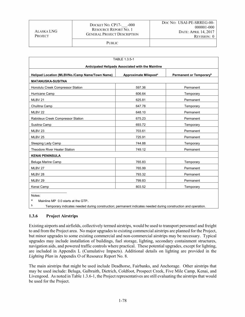
ALASKA LNG PROJECT
DOCKET NO. CP17-___-000 RESOURCE REPORT NO. 1
GENERAL PROJECT DESCRIPTION
DOC NO: USAI-PE-SRREG-00-000001-000
DATE: APRIL 14, 2017 REVISION: 0
PUBLIC
1-78
TABLE 1.3.5-1
Anticipated Helipads Associated with the Mainline
Helipad Location (MLBVNo./Camp Name/Town Name) Approximate Mileposta Permanent or Temporaryb
MATANUSKA-SUSITNA
Honolulu Creek Compressor Station 597.36 Permanent
Hurricane Camp 606.64 Temporary
MLBV 21 625.81 Permanent
Chulitna Camp 647.78 Temporary
MLBV 22 648.10 Permanent
Rabideux Creek Compressor Station 675.23 Permanent
Susitna Camp 693.72 Temporary
MLBV 23 703.61 Permanent
MLBV 25 725.91 Permanent
Sleeping Lady Camp 744.88 Temporary
Theodore River Heater Station 749.12 Permanent
KENAI PENINSULA
Beluga Marine Camp 765.83 Temporary
MLBV 27 765.99 Permanent
MLBV 28 793.32 Permanent
MLBV 29 799.83 Permanent
Kenai Camp 803.52 Temporary ____________________ Notes: a Mainline MP 0.0 starts at the GTP. b Temporary indicates needed during construction; permanent indicates needed during construction and operation.
1.3.6 Project Airstrips
Existing airports and airfields, collectively termed airstrips, would be used to transport personnel and freight to and from the Project area. No major upgrades to existing commercial airstrips are planned for the Project, but minor upgrades to some existing commercial and non-commercial airstrips may be necessary. Typical upgrades may include installation of buildings, fuel storage, lighting, secondary containment structures, navigation aids, and powered traffic controls where practical. These potential upgrades, except for lighting, are included in Appendix L (Cumulative Impacts). Additional details on lighting are provided in the Lighting Plan in Appendix O of Resource Report No. 8.
The main airstrips that might be used include Deadhorse, Fairbanks, and Anchorage. Other airstrips that may be used include: Beluga, Galbraith, Dietrich, Coldfoot, Prospect Creek, Five Mile Camp, Kenai, and Livengood. As noted in Table 1.3.6-1, the Project representatives are still evaluating the airstrips that would be used for the Project.

ALASKA LNG PROJECT
DOCKET NO. CP17-___-000 RESOURCE REPORT NO. 1
GENERAL PROJECT DESCRIPTION
DOC NO: USAI-PE-SRREG-00-000001-000
DATE: APRIL 14, 2017 REVISION: 0
PUBLIC
1-79
TABLE 1.3.6-1
Airstrips Under Evaluation by the Project
Airstrip Name Nearest Project
Pipeline Mileposta Upgrade Required to Meet
Project Standards Discussion
Deadhorse 10 No Full service airport, no improvement required.
Point. Thomson Facilities 0 (PTTL) No
Badami 19 (PTTL) Yes Currently owned by Miller Energy Resources. Condition is unknown; requires verification.
Franklin Bluffs 44 Yes Within Deadhorse service area.
Happy Valley 87 Yes Within Deadhorse service area.
Galbraith Lake 142 Yes Five miles from TAPS pump station #4 and close to Atigun Pass. Currently in use by TAPS for crew changes.
Dietrich Airport 207 Yes
Coldfoot 243 Yes
Prospect Creek 279 Yes Located at TAPS pump station #5. Currently in Use by TAPS for crew changes.
Kanuti 311 Yes This airstrip was used for TAPS construction and is situated near the TAPS Old Man Camp.
Five Mile Camp 352 Yes Located close to Yukon River crossing. Requires verification.
Livengood Camp 401 Yes Next to Livengood camp. Potentially upgradeable, requires verification.
Fairbanks International 450 No
Good airport, no upgrades required. Need to address utilization for personnel changes and project freight requirements. Hanger and transfer station for buses.
Nenana 474 TBD Requires investigation.
Healy 525 TBD Requires investigation.
Summit (Cantwell) 569 TBD Requires investigation.
Talkeetna 664 TBD Requires investigation.
Beluga 764 Yes Requires Investigation.
Anchorage International 764 No Full service international airport. No upgrade
required.
Kenai Municipal Airport 806 TBD Requires investigation.
Dutch Harbor N/A Yes
Seward 806 Yes Currently has commercial/charter service. Port may be used for pipe, equipment and supplies.
Valdez 755 No Port may be used for pipe, supplies, fuel and equipment. Currently has commercial service.
a Milepost provided is for the Mainline unless otherwise indicated

ALASKA LNG PROJECT
DOCKET NO. CP17-___-000 RESOURCE REPORT NO. 1
GENERAL PROJECT DESCRIPTION
DOC NO: USAI-PE-SRREG-00-000001-000
DATE: APRIL 14, 2017 REVISION: 0
PUBLIC
1-80
1.3.7 Project Material Sites
Various materials (e.g., sand, granular material, and stone) would be required for construction of the Project, including base material for work pads, aboveground facility sites, temporary construction facilities, access roads, and other uses. Material may also be used during construction for concrete production, temporary laydown, equipment staging, and other uses. The material required for these facilities would be obtained from material sites that are either existing or would be developed for the Project. A preliminary list of potential sources for these various materials is included in Resource Report No. 6, Section 6.3.1. The Project would require approximately 32 million cubic yards of granular fill for construction. This granular fill would be sourced from multiple locations over the seven-year construction period. Access to these material sites would be by winter road, all-weather road, Project footprint (e.g., pipeline ROW), or some combination of these.
At the conclusion of construction activities, material sites would likely either be used for other projects by the landowner (such as for road construction administered by ADOT&PF) or closed as per land use agreements and regulatory requirements. Additional details are provided in the Project’s Gravel Sourcing
Plan and Site Reclamation Measures, Resource Report No. 6, Appendix F.
1.3.7.1 Liquefaction Facility
Gravel, rock, and other aggregate material would be needed for construction of the Liquefaction Facility. This would include fill for the LNG Plant site, as well as materials for use offshore in support of construction of the Marine Terminal. Approximately 4.7 million cubic yards of granular material would be needed for fill during construction. Geophysical and geotechnical investigations at the proposed site indicate that significant quantities of onsite aggregate are suitable for road base and structural fill. The material located within the Liquefaction Facility site boundaries would be sufficient to provide the material needs of the Project for site preparation, and importation of fill material from off site is not planned. Additional details are provided in the Project’s Gravel Sourcing Plan and Site Reclamation Measures, Resource Report No. 6, Appendix F.
In addition to the structural fill, approximately 0.5 million cubic meters of sand and gravel would be required for ready mixed concrete. This material can be processed on site or sourced from multiple quarries that are located within 20 miles of the site. The materials sourced in the Kenai Peninsula area would be transported to the site by truck on Alaska highways, including the Seward Highway and the Kenai Spur Highway, or through the MOF on Cook Inlet.
At the facility site, bulk materials would be offloaded into a temporary storage location prior to use. A portion of the bulk granular materials would be installed as base materials offshore and would be transported by barge to the location.
Approximately 1.2 million cubic yards of vegetation would be removed during clearing and disposed of at an onsite or approved offsite location. The commercial use of the trees is marginal due to the previous harvesting combined with the spruce beetle damage. Approximately 2.5 million cubic yards of topsoil contains organic materials that are unsuitable for construction. The unsuitable material would be removed during the grubbing of the site and transported to an onsite or approved offsite stockpile location.

ALASKA LNG PROJECT
DOCKET NO. CP17-___-000 RESOURCE REPORT NO. 1
GENERAL PROJECT DESCRIPTION
DOC NO: USAI-PE-SRREG-00-000001-000
DATE: APRIL 14, 2017 REVISION: 0
PUBLIC
1-81
1.3.7.2 Pipeline Material Sites
The majority of the granular material required by the Project would be needed for pipeline construction. The estimated need for granular material is approximately 8.8 million cubic yards for the work pad and an additional 1.95 million cubic yards for bedding and padding of the pipe. Minor amounts would also be needed for weight bags, as fill to protect the ditch and workspace areas, and for slope stabilization, all estimated at approximately 0.56 million cubic yards. A potential list of existing and new sites is provided in the Project’s Gravel Sourcing Plan and Site Reclamation Measures, which is included in Resource Report No. 6, Appendix F. Most of the material required to support the pipeline would be for construction and either left in place or reclaimed as per landowner requirements. The material sites themselves would also be left in place or reclaimed per landowner agreements.
1.3.7.3 GTP Material Site
It is estimated that approximately 6.9 million cubic yards of granular material would be required during construction of the GTP. The Applicant proposes to use granular material excavated from the water reservoir to support the construction of other Project infrastructure. Additional details are provided in the Project’s Gravel Sourcing Plan and Site Reclamation Measures, which is included in Resource Report No. 6, Appendix F. Discussions are underway to determine whether existing mine sites could be used for early granular material supply until the reservoir and/or mine site is/are opened. Preliminary discussions indicate that the Put-23 mine could accommodate the initial granular material volumes required for the early stages of construction of the GTP.
1.3.7.3.1 Mine Site
A new granular material site approximately 1.4 miles (straight-line distance) south-southwest of the GTP site, 1 mile west of the existing Put-23 mine site, and less than 1 mile north of the Putuligayuk River has been explored. The exact location and layout of the mine site has not been finalized, but it is planned to be located within the study area identified on Figure 1.3.2-3. In addition, it is estimated that development of the new reservoir (adjacent to the mine site) would generate material to support GTP construction. Once the reservoir excavation meets design requirements, it would be filled and no longer be used as a granular resource.
Third-party material would be required until the new mine site is producing. It is anticipated that up to 1 million cubic yards of granular material could be acquired from the Put 23 mine or possibly from the ADOT&PF Pit 103, located south of the Deadhorse Airport.
1.3.8 Project Waste Management
A description of the proposed waste characterization procedures, estimated waste quantities, and waste handling/disposal procedures are provided in the Project’s draft Waste Management Plan. This plan addresses hazardous and non-hazardous waste materials in detail and is provided in Resource Report No. 8, Appendix J.

ALASKA LNG PROJECT
DOCKET NO. CP17-___-000 RESOURCE REPORT NO. 1
GENERAL PROJECT DESCRIPTION
DOC NO: USAI-PE-SRREG-00-000001-000
DATE: APRIL 14, 2017 REVISION: 0
PUBLIC
1-82
1.3.8.1 Liquefaction Facility Waste Management
Operational waste materials would be disposed of as required by federal, state, and local regulations. A description of the proposed waste characterization procedures, estimated waste quantities, and waste handling/disposal procedures is provided in the Project’s draft Waste Management Plan. Resource Report No. 8, Appendix J.
1.3.8.1.1 Temporary Domestic Wastewater Treatment Plant
A temporary domestic wastewater treatment plant would be located east of the construction camps. Vacuum trucks and wastewater collection lines would transport wastewater from the camps. Vacuum trucks would take the material to an approved disposal facility. The temporary construction treatment plant would be sized to treat domestic wastewater at a rate of approximately 50 gallons per person per day. The plant capacity is planned for approximately 250,000 gallons per day.
Discharge from the temporary sewage plant would be to a sediment basin on site that would discharge to Cook Inlet through an outfall. The wastewater would be tested prior to discharge in accordance with APDES permit requirements.
1.3.8.1.2 Operations Wastewater Treatment System
A wastewater treatment system would be located adjacent to the liquefaction trains and potable water treatment system (see below). The main liquid effluents would be:
Boiler blowdown;
Reject water from the water treatment system;
Drainage from areas outside of potential sources of contamination (e.g. processing train/facilities drainage); and
Sanitary effluent/black water (e.g., control rooms, administration buildings, security building).
Design of the wastewater treatment system would include provisions for segregation of effluent by source, collection, routing, treatment as necessary, and monitoring to minimize liquid effluents, facilitate selective recycle, and meet ADEC regulations. The wastewater treatment area would consist of the following subsystems:
Oily water; Contaminated stormwater; and Sanitary wastewater.
The surface runoff and oily water from collection sumps would be sent into an equalization tank for treatment. Once treated, the water would be sent to one of the three onsite ponds would serve as the receiving area prior to discharge. Treatment methods would be further defined during later stages of the

ALASKA LNG PROJECT
DOCKET NO. CP17-___-000 RESOURCE REPORT NO. 1
GENERAL PROJECT DESCRIPTION
DOC NO: USAI-PE-SRREG-00-000001-000
DATE: APRIL 14, 2017 REVISION: 0
PUBLIC
1-83
Project. The main discharge location of wastewater effluent streams would be a plant outfall to Cook Inlet shoreline near the trestle. An application for an APDES discharge permit would be filed prior to operations.
Runoff outside of operational areas would drain into stormwater ponds. Overflow of water from these ponds would also be discharged in accordance with APDES requirements via outfalls into Cook Inlet.
1.3.8.2 Pipeline Waste Management
Waste material generated during construction and operation of the pipelines would be managed according to federal, state, and local regulations. Material generated during construction is primarily construction wastes from packing of material and supplies, camp wastes, sanitary waste at camps, and construction debris (vegetation, rock, ice-rich soils, etc.). Disposal sites for the construction generated wastes are provided in the Gravel Sourcing Plan and Site Reclamation Measures, Resource Report No. 6, Appendix F. Disposal of other construction camp wastes and contractor generated wastes would be developed during final design and would generally follow the plan outline provided for the Project’s draft Waste Management
Plan in Resource Report No. 8, Appendix J.
1.3.8.3 GTP Waste Management
Operational or construction waste materials would be disposed of as required by federal, state, and local regulations. A description of the proposed waste characterization procedures, estimated waste quantities, and waste handling/disposal procedures is proved in the Project’s draft Waste Management Plan. This plan addresses hazardous and non-hazardous waste materials in detail and is provided in Resource Report No. 8, Appendix J.
1.3.9 Non-jurisdictional Facilities
There are five identifiable categories of facilities that (i) are outside the scope of the proposed Project, (ii) would be owned and operated by third parties, (iii) are beyond FERC’s jurisdiction under the NGA, but (iv) support or relate to the Project:
Modifications/new facilities at the PTU;
Modifications/new facilities at the PBU, including a new pipeline from GTP to the PBU to transfer GTP Byproduct back to the PBU;
Relocation of the Kenai Spur Highway;
Modifications to or construction of manufacturing facilities to fabricate Project components outside of Alaska; and
Third-party pipelines and associated infrastructure to transport natural gas from the gas interconnection points to markets within Alaska (Gas Interconnect Point Facilities).
The first three of these facilities are described in Sections 1.3.9.2 through 1.3.9.4. As explained in Section 1.3.9.1, the PTU Expansion project, PBU MGS project, and Kenai Spur Highway relocation project would

ALASKA LNG PROJECT
DOCKET NO. CP17-___-000 RESOURCE REPORT NO. 1
GENERAL PROJECT DESCRIPTION
DOC NO: USAI-PE-SRREG-00-000001-000
DATE: APRIL 14, 2017 REVISION: 0
PUBLIC
1-84
be “connected actions” that should be analyzed by FERC in the National Environmental Policy Act (NEPA) review for this Project Manufacturing facilities that may be constructed or modified to fabricate Project components may be considered by FERC as indirect effects of the Project. Gas Interconnect Point Facilities extending from interconnection points along the Mainline of the Project to provide in-state natural gas would be appropriately addressed by FERC as foreseeable future actions included within its cumulative impacts assessment.
1.3.9.1 Connected Actions Assessment
Under the NEPA (40 C.F.R. § 1508.25), “connected” actions must be analyzed under a single Environmental Impact Statement (EIS). Actions are connected if they:
Automatically trigger other actions that may require EISs;
Cannot or would not proceed unless other actions are taken previously or simultaneously; or
Are interdependent parts of a larger action and depend on the larger action for their justification.
The federal courts have reduced these “connected action” factors to a single question: “whether ‘each of the two projects would have taken place with or without the other and thus has independent utility.’”25
In addition, at 18 C.F.R. § 380.12(c)(2), FERC has directed applicants to identify and describe in Resource Report No. 1 all non-jurisdictional facilities, and to apply a four-factor test to determine whether FERC should include such facilities in its environmental review:
Whether the regulated activity comprises “merely a link” in a corridor-type project (e.g., a transportation or utility transmission project);
Whether there are aspects of the non-jurisdictional facility in the immediate vicinity of the regulated activity that uniquely determine the location and configuration of the regulated activity;
The extent to which the entire project would be within FERC’s jurisdiction; and
The extent of cumulative federal control and responsibility.
Applying these factors, applicants and FERC assess whether non-jurisdictional facilities are “integrally related” facilities over which “there is sufficient federal control and responsibility … to warrant environmental analysis of portions of the project outside of [FERC’s] direct sphere of influence.”26
The PTU and PBU modifications and new facilities described in sections 1.3.9.2 and 1.3.9.3, which could only be undertaken by the unit owners and operators, would be essential for the supply of natural gas from
25 Sierra Club v. BLM, 786 F.3d 1219, 1226 (9th Cir. 2015). 26 Guidance Manual for Environmental Report Preparation (FERC 2002), citing Algonquin Gas Transmission Co., 59 FERC 61,255 at 61,934
(1992).

ALASKA LNG PROJECT
DOCKET NO. CP17-___-000 RESOURCE REPORT NO. 1
GENERAL PROJECT DESCRIPTION
DOC NO: USAI-PE-SRREG-00-000001-000
DATE: APRIL 14, 2017 REVISION: 0
PUBLIC
1-85
the PTU and PBU to the Project. These non-jurisdictional facilities would not have independent utility apart from the Project; nor would the proposed Project under any feasible configuration be practicable without them. Construction and operation of these facilities would necessarily occur in the same time frame with development and operation of the proposed Project, and dictate, in part, location and configuration of the PTU and PBU Transmission Lines and the GTP. Because these non-jurisdictional facilities are integral to the proposed Project, NEPA mandates FERC’s inclusion of them in its environmental analysis as “connected actions.”
Relocation of the Kenai Spur Highway, a component of the National Highway System, is described in Section 1.3.9.4. The relocation, which could only be accomplished by the State of Alaska (ADOT&PF), would facilitate construction at and use of the Project’s proposed Nikiski Liquefaction Facility site. Relocation of the Kenai Spur Highway would have independent utility to the local community and industries, but the likelihood, timing, and configuration of this relocation would be uncertain but for the Project. In addition, the proposed Project as a whole would have independent utility from relocation of the Kenai Spur Highway; however, the proposed location for the Liquefaction Facility would not. This proposed Liquefaction Facility location would be compromised without relocation of the Kenai Spur Highway, whether as proposed or to another alternative route. As such, relocation of the Kenai Spur Highway is of direct consequence to the location and configuration of the Project. The totality of these circumstances warrant FERC’s inclusion of the Kenai Spur Highway relocation project in its environmental analysis as a connected action.
Construction of the Project would require the fabrication of new materials and equipment for use in the LNG facility, pipeline, and GTP at facilities that have yet to be identified. These facilities are likely to be located within the contiguous United States and would be subject to federal, state, and local environmental reviews and standards; however, the nature of these facilities, their locations within the United States, and the extent to which major facility modifications or new construction will be required to support such fabrication is not yet known and is unlikely to be known until after the Project has been certified and approved for construction. Although what work might be required to support fabrication of Project components is still being evaluated, it is foreseeable that such work would be required in support of, and caused by, the Project. In such cases, the Council on Environmental Quality (CEQ) regulations anticipate that an EIS would consider the potential effects of such activities as “indirect effects” of the proposed action 40 C.F.R. §1508.8(b). To the extent typical impacts of manufacturing facility construction and operation can be identified and effects evaluated, these effects will be described and analyzed in Resource Report Nos. 2 through 9 in support of FERC’s effects analysis.
The last category of non-jurisdictional facilities consists of Gas Interconnect Point Facilities that may extend from the gas interconnection points to make natural gas available to utility or industrial users within Alaska. Future Gas Interconnect Point Facilities would be undertaken by as-yet unknown third parties. As described in Section 1.3.2.1.3.4, at this time, three interconnection points have been identified: (i) near MP 441 (Fairbanks/North Star Gas Interconnect Point); (ii) near MP 764 (Anchorage/Matanuska-Susitna Gas Interconnect Point); and (iii) near MP 806 (Kenai Peninsula Gas Interconnect Point). The location of other interconnection points is unknown at this time, as are the owner/operator, facilities and size/configurations, route/location and timing for construction and operation. There are no currently pending proposals for any Gas Interconnect Point Facilities, and the likelihood and timing for such proposals applicable to one or more of the interconnection points is uncertain.
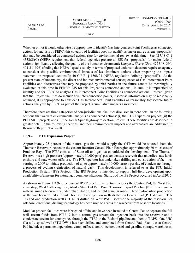
ALASKA LNG PROJECT
DOCKET NO. CP17-___-000 RESOURCE REPORT NO. 1
GENERAL PROJECT DESCRIPTION
DOC NO: USAI-PE-SRREG-00-000001-000
DATE: APRIL 14, 2017 REVISION: 0
PUBLIC
1-86
Whether or not it would otherwise be appropriate to identify Gas Interconnect Point Facilities as connected actions for analysis by FERC, this category of facilities does not qualify as one or more current “proposals” that may be considered as connected actions ripe for environmental review at this time. See 42 U.S.C. § 4332(2)(C) (NEPA requirement that federal agencies prepare an EIS for “proposals” for major federal actions significantly affecting the quality of the human environment); Kleppe v. Sierra Club, 427 U.S. 390, 401-2 (1976) (finding that NEPA “speaks solely in terms of proposed actions; it does not require an agency to consider the possible environmental impacts of less imminent actions when preparing the impact statement on proposed actions.”); 40 C.F.R. § 1508.23 (NEPA regulation defining “proposal”). At the present state of uncertainty, the direct and indirect environmental consequences of Gas Interconnect Point Facilities and alternatives that may be proposed by third parties in the future cannot be meaningfully evaluated at this time in FERC’s EIS for this Project as connected actions. In sum, it is impractical to identify and for FERC to analyze Gas Interconnect Point Facilities as connected actions. Instead, given that the Project facilities do include five interconnection points, insofar as information may be reasonably obtained, it is appropriate to consider Gas Interconnect Point Facilities as reasonably foreseeable future actions analyzed by FERC as part of the Project’s cumulative impacts assessment.
Therefore, there are three categories of non-jurisdictional facilities discussed in more detail in the following sections that warrant environmental analysis as connected actions: (i) the PTU Expansion project; (ii) the PBU MGS project; and (iii) the Kenai Spur Highway relocation project. These facilities are described in greater detail in the following sections, and their environmental impacts and alternatives are addressed in Resource Report Nos. 2–10.
1.3.9.2 PTU Expansion Project
Approximately 25 percent of the natural gas that would supply the GTP would be sourced from the Thomson Reservoir located in the eastern Beaufort Coastal Plain Ecoregion approximately 60 miles east of Prudhoe Bay. The PTU consists of State oil and gas leases unitized for development. The Thomson Reservoir is a high-pressure (approximately 10,000 psig) gas condensate reservoir that underlies state lands onshore and state waters offshore. The PTU operator has undertaken drilling and construction of facilities starting in 2009 to initiate production of up to approximately 10,000 barrels per day of condensate through a process of cycling (reinjection of natural gas). This development is referred to as the PTU Initial Production System (IPS) Project. The IPS Project is intended to support full-field development upon availability of a means for natural gas commercialization. Startup of the IPS Project occurred in April 2016.
As shown in Figure 1.3.9-1, the current IPS Project infrastructure includes the Central Pad, the West Pad, an airstrip, West Gathering Line, Alaska State C-1 Pad, Point Thomson Export Pipeline (PTEP), a granular material mine site currently under rehabilitation, and in-field granular roads. Three hydrocarbon production wells have been drilled at Point Thomson: two injection wells drilled on Central Pad (PTU-15 and PTU-16) and one production well (PTU-17) drilled on West Pad. Because the majority of the reservoir lies offshore, directional drilling technology has been used to access the reservoir from onshore locations.
Modular process facilities were fabricated offsite and have been installed at Central Pad to separate the full well stream fluids from PTU-17 into a natural gas stream for injection back into the reservoir and a condensate stream for conveyance through the PTEP to the Badami pipeline and then to TAPS. One UIC Class I disposal well (PTU-DW1) has been drilled and completed from Central Pad. Facilities at Central Pad include a permanent operations camp, offices, control center, diesel and gasoline storage, warehouses,

ALASKA LNG PROJECT
DOCKET NO. CP17-___-000 RESOURCE REPORT NO. 1
GENERAL PROJECT DESCRIPTION
DOC NO: USAI-PE-SRREG-00-000001-000
DATE: APRIL 14, 2017 REVISION: 0
PUBLIC
1-87
communications equipment, utilities, power generation, and a high-pressure/low-pressure combination emergency flare system. Marine facilities to support seasonal barging, sealift, and emergency response include a service pier, sealift bulkhead, and emergency response boat launch.
The IPS Project infrastructure would need to be expanded to produce gas for delivery to the PTTL. The PTU operator is currently developing the PTU Expansion project. The proposed PTU Expansion project would integrate with the IPS facilities, drilling, and infrastructure to produce the natural gas instead of reinjecting it back into the reservoir. The project would support full field production of natural gas and condensate from the Thomson Reservoir. The PTU Expansion project facilities would be designed, permitted, constructed, and operated by the PTU operator. The timing of construction would coincide with the Project to support commercial delivery of natural gas to the first gas conditioning train at the GTP.
The PTU Expansion project facilities are being designed to produce rates of up to approximately 57,000 barrels per day of associated condensate and approximately 920 MMSCF/D of exported gas.27 The PTU Expansion project facilities would be collocated and integrated with IPS processing facilities to the extent practicable.
1.3.9.2.1 Infrastructure and Facilities
The PTU Expansion project’s design is based upon the use of existing infrastructure and facilities to the greatest extent practicable. An overview of the project facilities is shown on Figure 1.3.9-1. The scope of new development for the PTU Expansion project would include:
Pad Expansion
○ Incremental Expansion of the granular footprint of the Central Pad (approximately 26 acres) to accommodate additional processing facilities; and
○ Construction of the East Pad and East Pad Road (previously permitted by the IPS Project determined not to be required for IPS start-up) (approximately 38 acres).
Pipelines
○ Installation of the previously permitted East Gathering Line (corrosion-resistant, alloy-lined 14-inch-diameter steel pipe) installed on VSMs between the East Pad and Central Pad to deliver produced hydrocarbon stream to the Central Processing Facility (CPF).
Granular Material Mine Development and Rehabilitation
○ Development and rehabilitation of a new granular material mine site (approximately 43 acres) to produce approximately 1–2 million cubic yards of granular material.
27 Based on variability in facility and reservoir performance, production could exceed 920 mmscfd at times. AOGCC has approved a requested maximum allowable annual average gas offtake of 1.1 BCFD from Point Thomson (Conservation Order No. 719 dated October 15, 2015) to accommodate contingency for debottlenecking, operational flexibility, and fuel gas.

WEST PAD WEST GATHERINGLINE CENTRAL PAD
EAST GATHERINGLINE
ALASKA STATE C-1 PAD
EAST PAD
EAST PADROAD
AIRSTRIP
CLOSED GRAVEL MINE SITE - UNDER REHABILITATION
CENTRAL PAD ROAD
WEST PAD ROAD
GAS EXPANSIONGRAVEL MINE
ALASKA LNG PROJECTINFRASTRUCTUREAND FACILITIES
POINT THOMSONEXPORT PIPELINE
LEGEND
0 1 20.5 Miles
PTU FACILITIES
!°
SCALE:1 of 1
AGDCPREPARED BY:1:75,000
2017-02-27 SHEET:DATE:X:\AKLNG\Resource Reports\RR01\Figure 1_3_9_1 PTU Facilities.mxd
Planned Gas Expansion ProjectInfrastructurePermitted but Not YetConstructedExisting Infrastructure
Point ThomsonExport PipelineWest Gathering LineEast Gathering LineAlaska LNG ProjectInfrastructure and Facilities
FIGURE 1.3.9-1!
!
!
CANADARUSSIA
Arctic Ocean
Pacific Ocean
Bering Sea ANCHORAGE
FAIRBANKS
PRUDHOE BAY
VICINITY MAP DISCLAIMERThe information contained herein is for informational or planning purposes only, It does not nor should it be deemed to be an offer, request or proposals for rights or occupation of any kind. The Alaska LNG Project Participants and their respective officers, employees and agents, make no warranty, implied or otherwise, nor accept any liability, as to the accuracy or completeness of the information contained inthese documents, drawings or electronic files. Do not removeor delete this note from document, drawing or electronic file.
B e a u f o r t S e a

ALASKA LNG PROJECT
DOCKET NO. CP17-___-000 RESOURCE REPORT NO. 1
GENERAL PROJECT DESCRIPTION
DOC NO: USAI-PE-SRREG-00-000001-000
DATE: APRIL 14, 2017 REVISION: 0
PUBLIC
1-90
Facilities and Support Infrastructure
○ Offsite fabrication of process facility modules delivered to Point Thomson by sealift and trucks that would separate gas and liquids, dehydrate and stabilize the condensate for delivery to the PTEP, dehydrate and condition the natural gas for delivery to the PTTL, and provide additional power generation and produced water handling capacity;
○ Installation of a high integrity pressure protective system (HIPPS) to accompany the existing high-pressure/low-pressure combination flare;
○ Minor expansion of the sectional bridge and installation of additional mooring dolphins (previously permitted) to enable module delivery at the marine facilities; and
○ Minor dredging (estimated to be less than approximately 5,000 cubic yards) near the sealift bulkhead to enable module delivery; screeding as required. Dredging would take place in the winter months by cutting through the ice. Any excess material removed would be placed along the coast to the west of Point Thomson marine facilities Minor screeding may take place in summer months immediately prior to arrival of barges. Maintenance dredging is not anticipated to be required.
Existing utilities would be leveraged and supplemented as required to accommodate increased capacity from new facilities. The construction and drilling workforce would be billeted in temporary construction camps at Point Thomson as well as camps at Prudhoe Bay and Badami. The existing permanent operations camp at Central Pad would also be used during construction, drilling, and operations. Waste would be managed on site to the extent practicable using an incinerator and disposal wells; waste would be hauled offsite to approved disposal facilities when required.
1.3.9.2.2 Reservoir and Drilling
Full field development at Point Thomson would enable commercialization of an estimated 8 trillion cubic feet of natural gas in place and associated natural gas condensate. Point Thomson gas represents approximately 25 percent of discovered natural gas resources on the Alaska North Slope. The PTU Expansion project would include:
Drilling of six new production wells from two pads, including three from Central Pad, and three from East Pad;
Conversion of the two gas injection wells on Central Pad to production wells; and
Drilling of one new UIC Class I disposal well at Central Pad (previously permitted for IPS).
The crest of the Thomson Reservoir is over 12,000 feet deep and reservoir pressures at Point Thomson (more than 10,000 psig) are much higher than those found in hydrocarbon production locations elsewhere in Alaska. The high pressure of the reservoir requires special design considerations for drilling, process facilities, and materials selection. The flowing wellhead pressure is estimated to be over 6,500 psig.

ALASKA LNG PROJECT
DOCKET NO. CP17-___-000 RESOURCE REPORT NO. 1
GENERAL PROJECT DESCRIPTION
DOC NO: USAI-PE-SRREG-00-000001-000
DATE: APRIL 14, 2017 REVISION: 0
PUBLIC
1-91
The hydrocarbon production wells would be designed to address challenges related to surface permafrost management, a narrow margin high pressure targeted gas zone, sand control completions, and long reach directional drilling. Each well would have a specific design to meet the specific reservoir target and challenges. Drilling in permafrost would also require special considerations. Insulated conductors for production and disposal wells would be used to minimize heat transfer between hydrocarbon fluids and permafrost. Thermosyphons would be installed at new wells to prevent near-bore permafrost from thawing. A well house would be installed over the wells to protect them and local instruments from the elements.
The reservoir pressure at Point Thomson would be adequate to meet the process facility requirements in the early years of production. As hydrocarbons are produced from the reservoir, the reservoir pressure would decline. Booster compression is expected to be required approximately 15 years after facilities start-up.
1.3.9.2.3 Construction and Logistics
Granular roads and pads would be of sufficient thickness to support the loads. Local hydrology would be studied and incorporated into the designs to facilitate natural hydrologic flow during peak breakup periods.
The logistics required to transport and support personnel, materials, equipment, and equipment modules for a remote site development are challenging and expensive. Year-round access is essential, both for routine operations and for responding to emergencies. Significant work scopes would be executed during limited seasonal windows by means of winter ice roads, summer barging, and early winter tundra travel. These brief seasonal windows are uncertain due to unpredictable variations in weather, ice conditions, wildlife interactions, and other circumstances. Maximizing use of these limited access opportunities would be paramount for achieving efficient logistics for construction, drilling, and operations.
Conventional trucks provide the most effective and efficient method of delivering equipment and material to the Point Thomson site. Trucked shipments would be transported to Deadhorse on State highways and then onward to the PTU Expansion project site via annual winter ice road. Air transportation would be used year-round for personnel transit, emergency support, and delivery of equipment, materials, and supplies during periods when there is no ice road or sea access. In the summer, barge and boat transport would be used as required, between dock heads outside Alaska and at Prudhoe Bay, Endicott, and Point Thomson.
Modularization is the most efficient way to fabricate, transport, and install facilities and equipment at the PTU Expansion project site. Modules would be fabricated offsite, transported to the site by sealift, and installed for use. Module design would take into account the Arctic conditions through implementation of winterization techniques. Oceangoing barges would be used to transport sealift large modules and heavy equipment to the site. A barge bridge would be created by ballasting and grounding the oceangoing barges in series, enabling module roll-off from the barges onto Central Pad. One sealift is anticipated for the expansion work.
1.3.9.3 PBU Major Gas Sales (MGS) Project
Approximately 75 percent of the natural gas that would supply the Project would be sourced from the Prudhoe Bay field. The PBU has been a large oil producing and gas cycling operation since 1977. Reservoir fluids from approximately 900 producing wells located on 40 drilling pads are routed to oil, water, and gas separation facilities. The gas produced at each separation facility is dehydrated prior to

ALASKA LNG PROJECT
DOCKET NO. CP17-___-000 RESOURCE REPORT NO. 1
GENERAL PROJECT DESCRIPTION
DOC NO: USAI-PE-SRREG-00-000001-000
DATE: APRIL 14, 2017 REVISION: 0
PUBLIC
1-92
being discharged into a pipeline network that ultimately delivers the gas to the PBU CGF. The PBU CGF is a propane refrigeration-based gas process plant that is designed to extract components in the natural gas that can be fractionated into natural gas liquids and miscible injectant products. The vast majority of the processed natural gas is then routed via various gas pipelines to gas injection compressors located at the Central Compression Plant and the PBU CGF for injection into the reservoir gas cap.
The purpose of the PBU MGS Project is to allow the natural gas currently being produced, compressed, and reinjected within the PBU to be transported to the GTP for processing to remove byproduct and compressing of the hydrocarbon gas to enter the Mainline for transport to the LNG Plant. Much of the existing infrastructure in the field currently supports gas handling, but some modifications to the existing facilities, along with the installation of some new minor facilities (modules), would be required to deliver gas to the GTP for export and sale. The PBU MGS Project also supports the injection of GTP Byproduct into PBU. Because existing wells are currently producing gas along with oil and water, the level of drilling activity to support MGS would be similar to the current level of activity. No improvements to infrastructure at West Dock or to PBU roads are planned solely for the PBU MGS Project. As shown on Figure 1.3.9-2, the PBU MGS Project includes the addition of the facilities discussed in the following subsections.
New Granular Material Infrastructure
The PBU CGF Pad Expansion would be an expansion of an approximately 5-acre pad (requiring approximately 150,000 cubic yards of granular material) at the PBU CGF that would accommodate two new modules: a valve module and a metering module for feed gas.
Feed Gas and Propane Gas Pipelines
Currently, gas from throughout the field is delivered to the PBU CGF system via two existing 60-inch pipelines. The PBU MGS Project includes three new approximately 48-inch pipelines from the PBU CGF LTS system, which would enter a new valve module on the CGF Pad. Upon exiting the new valve module, the new pipelines would combine into a single larger pipeline to deliver gas to a new metering module on the PBU CGF pad. After the gas is metered, it would be delivered to the PBTL, which would connect the PBU CGF metering module to GTP.
Following commissioning of the PBU MGS Project, an additional 5-mile-long gas pipeline from the Lisburne Production Center to PBU CGF may be constructed.
Byproduct Pipelines
New pipelines would be constructed to deliver GTP Byproduct to Well Pad W (W Pad), Well Pad Z (Z Pad), the Apex Gas Injection (AGI) Pad, Drill Site 9, Drill Site 16, and two Point McIntyre drill sites (PM1 and PM2).
A new pipeline and tie-ins to W and Z Pads would be constructed from the GTP Byproduct-receiving module at PBU CGF to the Eileen West End junction, then onto connections at W-Pad and Z-Pad. This pipeline would be approximately 25 miles in total length;
A new pipeline from the GTP Byproduct-receiving module to the AGI Pad that would be approximately 3 miles in length;

ALASKA LNG PROJECT
DOCKET NO. CP17-___-000 RESOURCE REPORT NO. 1
GENERAL PROJECT DESCRIPTION
DOC NO: USAI-PE-SRREG-00-000001-000
DATE: APRIL 14, 2017 REVISION: 0
PUBLIC
1-93
A new pipeline from the GTP Byproduct-receiving module to FS2 and Drill Sites 9 and 16 that would be approximately 8 miles in length; and
A new pipeline from the GTP Byproduct-receiving module to PM1/2 that would be approximately 8 miles in length.
Pipeline tie-ins and associated piping and valves would link the GTP Byproduct line to existing infrastructure on the pad. The PBU may have additional modules to support the GTP Byproduct injection and pipelines may go to other locations for GTP Byproduct injection. The PBU may add a vent stack at Z pad to allow for the pipeline to be depressurized for maintenance activities on the system.
Wells and Tie-Ins
Within a few years prior to or following commissioning of the Project, approximately 10 new production and injection wells may be drilled within PBU to enhance gas recovery. The number of new wells and schedule for their completion would be determined by multiple factors related to gas recovery for sales and GTP Byproduct injection. The number of new wells to support PBU MGS would be within the range of new gas injection or oil production wells anticipated for continued life of the field. Additionally, some existing wells would become obsolete and be shut in as part of normal field operations. Furthermore, the PBU MGS Project would include well tie-in work to support GTP Byproduct injection at W Pad, Z Pad, AGI Pad, and PM1/2.
Well work-overs of existing wells would be necessary to support PBU MGS. Well work-overs are common practice in the Prudhoe Bay Unit. The need for well work-overs would be determined based on multiple factors related to field efficiency, gas sales, gas injection, oil production, GTP Byproduct injection, and well integrity; these work-overs are not anticipated to result in an increase in overall work-overs at PBU above current levels.
Construction
Construction of the PBU MGS Project would be completed in a staged manner over a four-year period and would be completed by the PBU operator in the same timeframe as GTP construction. Construction would take place during the winter, and pipelines would be placed on VSMs following standard North Slope construction practices. The PBU MGS Project may require additional camp space to accommodate workers during the construction period. If needed, a mobile 200-person camp would be located on existing pads near construction activities.
Operations
The PBU MGS Project would include use of existing infrastructure to support gas production and GTP Byproduct injection. An increase in water use or emissions is not anticipated in support of operation of the PBU MGS Project. Water would be sourced from permitted sources, remain within permitted volumes, conducted according to associated permitting requirements. Emission increases at Central Compression Plant and PBU CGF resulting from PBU MGS development are not anticipated at this time, and these facilities would therefore continue to operate under their Title V permits.

B e a u f o r t S e a
West DockModule Staging
Pad
GTP OperationsCenter Pad
GTP Pad
Mine Site
Reservoir
Pipeline ROW
CGF
Drill Site 16
Apex Gas Injection Pad
Skid 50 Pad
Drill Site 9
Well Pad Z
Well Pad W
P r u d h o eB a y
EWE Junction
LEGEND
0 5 Miles
PBU MGSFACILITIES
!°
SCALE:1 of 1
AGDCPREPARED BY:1:225,000
2017-02-27 SHEET:DATE:X:\AKLNG\Resource Reports\RR01\Figure 1_3_9_2 PBU MGS Facilities.mxd
FIGURE 1.3.9-2!
!
!
CANADARUSSIA
Arctic Ocean
Pacific Ocean
Bering Sea ANCHORAGE
FAIRBANKS
PRUDHOE BAY
VICINITY MAP DISCLAIMERThe information contained herein is for informational or planning purposes only, It does not nor should it be deemed to be an offer, request or proposals for rights or occupation of any kind. The Alaska LNG Project Participants and their respective officers, employees and agents, make no warranty, implied or otherwise, nor accept any liability, as to the accuracy or completeness of the information contained inthese documents, drawings or electronic files. Do not removeor delete this note from document, drawing or electronic file.
Prudhoe Bay TransmissionLineByproduct Distribution LinePBU Gas Sales PipelineAlaska LNG Rev C2 Route
Point ThomsonTransmission LineGTP FacilityExisting PBU Pipelinesand Facilities

ALASKA LNG PROJECT
DOCKET NO. CP17-___-000 RESOURCE REPORT NO. 1
GENERAL PROJECT DESCRIPTION
DOC NO: USAI-PE-SRREG-00-000001-000
DATE: APRIL 14, 2017 REVISION: 0
PUBLIC
1-95
The estimated life of the PBU MGS facilities is approximately 30 years. Standard maintenance of facilities would be conducted to ensure gas quality standards, maintenance of pipelines, and well workovers.
1.3.9.4 Kenai Spur Highway Relocation Project
The Kenai Spur Highway is part of the National Highway System that provides intermodal connection from the Sterling Highway (Alaska Highway 1) to the port facility owned and operated by Offshore Systems Kenai, which is located at the north end of Nikishka Beach Road, just north of the Kenai Spur Highway at about Highway MP 26.5. The planned Liquefaction Facility location would require that an approximately 1.33-mile segment of the existing Kenai Spur Highway be relocated to the east to enhance public safety and avoid potential conflicts with the proposed Liquefaction Facility. It is anticipated that the relocation would be completed prior to the start of Project construction.
The existing Kenai Spur Highway is a two-lane road that serves local and regional traffic with a 55-mph speed limit. To meet ADOT&PF standards, the relocated highway would also have two lanes, shoulders and a 55-mph speed limit. The relocated highway would be designed to accommodate anticipated traffic volumes in the study area beyond 2025.
The Project representatives are working with ADOT&PF and Kenai Peninsula Borough on the highway relocation planning including routing discussions, public engagement, permitting, and construction. The ongoing relocation study examined highway relocation routes beginning near Kenai Spur Highway MP 18 and ending near MP 25. Figure 1.3.9-3 provides a summary of preliminary options under consideration. These options are being evaluated with a variety of criteria including environmental features, potential impacts to local residents and businesses, ROW acquisition, traffic considerations, utilities relocation, geotechnical features, road design, and construction timing.
1.4 LAND REQUIREMENTS
The Project’s design includes approximately 68,000 acres of land that would be temporarily affected by construction of the Project. Following completion of construction, approximately 8,600 of these acres would be used for operation of the Project facilities. A summary of the acreages affected during construction and operation of the Project facilities is shown in Table 1.4-1.
The proposed locations of major facilities, pipeline route (Revision C2), and offsite work areas are depicted on aerial imagery and USGS maps provided in Appendix A. Preliminary Plot Plans of aboveground facilities are provided in Appendix B.
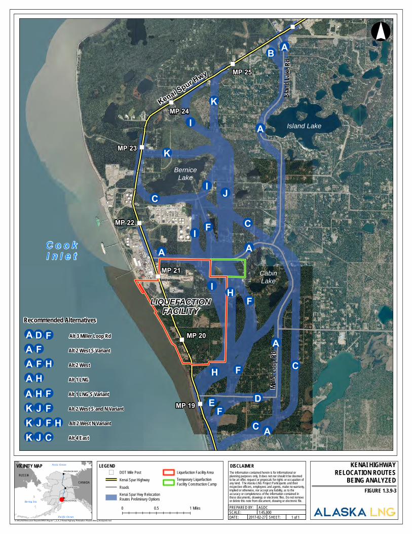
")
")
")
")
")
")
")
")
C o o kI n l e t
LIQUEFACTIONFACILITY
Kenai Spur Hwy
CabinLake
Island Lake
BerniceLake
MP 25
MP 24
MP 23
MP 22
MP 21
MP 20
MP 19
Miller
Loop
RdIsla
nd La
ke Rd
LEGEND
0 0.5 1 Miles
KENAI HIGHWAYRELOCATION ROUTES
BEING ANALYZED
!°
SCALE:1 of 1
AGDCPREPARED BY:1:45,000
2017-02-27 SHEET:DATE:X:\AKLNG\Resource Reports\RR01\Figure 1_3_9_3 Kenai Highway Relocation Routes Being Analyzed.mxd
") DOT Mile PostKenai Spur HighwayRoadsKenai Spur Hwy RelocationRoutes Preliminary Options
Liquefaction Facility AreaTemporary LiquefactionFacility Construction Camp
FIGURE 1.3.9-3
DISCLAIMERThe information contained herein is for informational or planning purposes only, It does not nor should it be deemed to be an offer, request or proposals for rights or occupation of any kind. The Alaska LNG Project Participants and their respective officers, employees and agents, make no warranty, implied or otherwise, nor accept any liability, as to the accuracy or completeness of the information contained inthese documents, drawings or electronic files. Do not removeor delete this note from document, drawing or electronic file.!
!
!
CANADARUSSIA
Arctic Ocean
Pacific Ocean
Bering Sea ANCHORAGE
FAIRBANKS
PRUDHOE BAY
VICINITY MAP
¬A
¬A
¬A ¬A
¬A
¬A¬B
¬C
¬C
¬C
¬C
¬D¬E
¬F
¬F
¬F
¬F
¬I
¬I
¬I
¬I
¬K
¬H
¬K
¬H
¬J
¬A
¬C
¬F
¬H¬J¬K Alt 4 East
Alt 3 Miller Loop Rd
Alt 2 West S Variant
Alt 2 West S and N Variant
¬J¬F
¬A¬F¬A
¬D¬F
¬K¬K¬J¬F
Alt 2 West N Variant
¬F¬H Alt 2 West
¬A¬H Alt 1 LNG S Variant
¬A¬H Alt 1 LNG
Recommended Alternatives
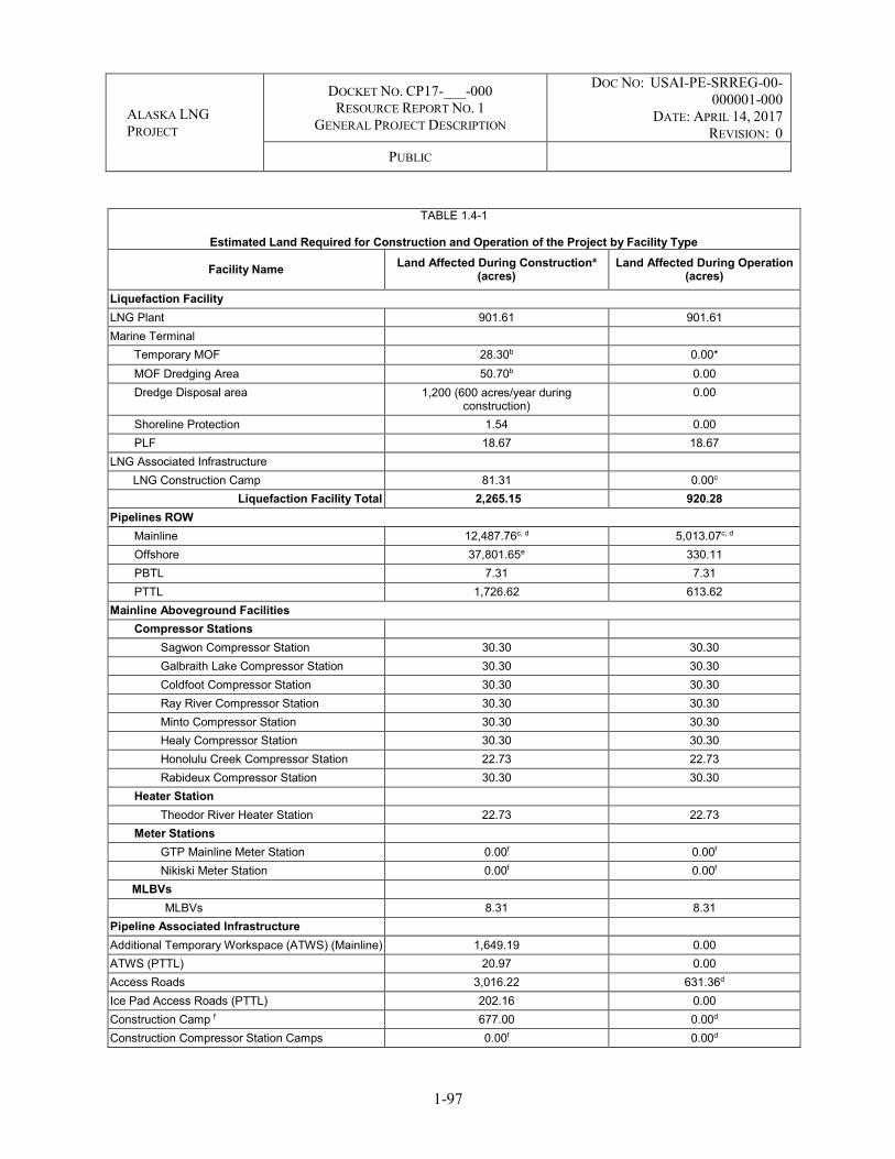
ALASKA LNG PROJECT
DOCKET NO. CP17-___-000 RESOURCE REPORT NO. 1
GENERAL PROJECT DESCRIPTION
DOC NO: USAI-PE-SRREG-00-000001-000
DATE: APRIL 14, 2017 REVISION: 0
PUBLIC
1-97
TABLE 1.4-1
Estimated Land Required for Construction and Operation of the Project by Facility Type
Facility Name Land Affected During Constructiona (acres)
Land Affected During Operation (acres)
Liquefaction Facility LNG Plant 901.61 901.61 Marine Terminal
Temporary MOF 28.30b 0.00* MOF Dredging Area 50.70b 0.00 Dredge Disposal area 1,200 (600 acres/year during
construction) 0.00
Shoreline Protection 1.54 0.00 PLF 18.67 18.67
LNG Associated Infrastructure LNG Construction Camp 81.31 0.00c
Liquefaction Facility Total 2,265.15 920.28 Pipelines ROW
Mainline 12,487.76c, d 5,013.07c, d Offshore 37,801.65e 330.11 PBTL 7.31 7.31 PTTL 1,726.62 613.62
Mainline Aboveground Facilities Compressor Stations
Sagwon Compressor Station 30.30 30.30 Galbraith Lake Compressor Station 30.30 30.30 Coldfoot Compressor Station 30.30 30.30 Ray River Compressor Station 30.30 30.30 Minto Compressor Station 30.30 30.30 Healy Compressor Station 30.30 30.30 Honolulu Creek Compressor Station 22.73 22.73 Rabideux Compressor Station 30.30 30.30
Heater Station Theodor River Heater Station 22.73 22.73
Meter Stations GTP Mainline Meter Station 0.00f 0.00f Nikiski Meter Station 0.00f 0.00f
MLBVs MLBVs 8.31 8.31
Pipeline Associated Infrastructure Additional Temporary Workspace (ATWS) (Mainline) 1,649.19 0.00 ATWS (PTTL) 20.97 0.00 Access Roads 3,016.22 631.36d Ice Pad Access Roads (PTTL) 202.16 0.00 Construction Camp f 677.00 0.00d Construction Compressor Station Camps 0.00f 0.00d

ALASKA LNG PROJECT
DOCKET NO. CP17-___-000 RESOURCE REPORT NO. 1
GENERAL PROJECT DESCRIPTION
DOC NO: USAI-PE-SRREG-00-000001-000
DATE: APRIL 14, 2017 REVISION: 0
PUBLIC
1-98
TABLE 1.4-1
Estimated Land Required for Construction and Operation of the Project by Facility Type
Facility Name Land Affected During Constructiona (acres)
Land Affected During Operation (acres)
Construction Camp (PTTL) f 97.22 0.00d Pipe Storage Yards 474.20 0.00d Pipe Storage Yards (PTTL) 28.01 0.00d Disposal Sites 259.15 0.00 Double Joining Yards 199.74 0.00 Material Sites 5,755.45 0.00d Railroad Spurs 10.87 0.00d Railroad Work Pads 36.70 0.00d Helipads (Mainline) 4.36 4.36 Helipad (PTTL) 0.57 0.57 PTTL Aboveground Facilities MLBVs 0.41 0.41
Point Thomson Meter Station 0.47 0.47 Mainline Total 62,973.74 6,250.27
PTTL Total 2,076.4 615.07 PBTL Total 7.31 7.31
GTP GTP Padg 227.88 227.88 Operations Center Pad 56.00 56.00
GTP Associated Infrastructure
Module Staging Area 86.58 0.00h West Dock Modification/Dock Head 4 Construction 31.05 0.00h
Barge Bridge 2.58 0.00h Turning Basin 13.70 0.00 Access Roads 258.81 258.81 Material (Mine) Site 141.16 141.16 Water Reservoir and Pump Facilities 35.12 35.12 Associated Transfer Pipelines 70.32 70.32 Pioneer Camp 30.00 0.00g Ice Pads 2.75 0.00
GTP Total 955.95 789.29 TOTAL FOOTPRINT 68,290.94 8,576.77

ALASKA LNG PROJECT
DOCKET NO. CP17-___-000 RESOURCE REPORT NO. 1
GENERAL PROJECT DESCRIPTION
DOC NO: USAI-PE-SRREG-00-000001-000
DATE: APRIL 14, 2017 REVISION: 0
PUBLIC
1-99
TABLE 1.4-1
Estimated Land Required for Construction and Operation of the Project by Facility Type
Facility Name Land Affected During Constructiona (acres)
Land Affected During Operation (acres)
____________________ a Construction acreage includes operational areas. b The MOF is a total of 28.3 acres; however, 16.98 acres is included within the MOF dredging footprint. c Preliminary estimate of Mainline land affected during construction and land affected during operation is for the Revision C2
route. ROW widths vary by construction method across the route and would be 53.5 feet for operations. Includes travel and bypass lanes as temporary construction footprint.
d Although granular material would be used to expand/improve existing access roads, camp sites, pipe yard sites and the construction ROW and not removed after construction is completed, the impact is only reported as the permanently maintained footprint for operations. Any impact of granular material left in temporary work areas or along the ROW is addressed in Resource Report Nos. 2, 3, and 8. Leaving the granular material in place is subject to landowner agreements.
e Includes the width of anchoring the offshore pipelay barge, currently assuming a 2.5-mile-wide anchor spread (total). The majority of the construction ROW would not be disturbed during construction.
f Acreage used for the construction and operation of a facility is 0.0 when it occurs within the construction or operation footprint of another facility of the construction or permanent footprint for that facility. Additional acreage is noted if the facility is placed outside of these areas.
g Construction/Operations camp is located on a pad connected to the GTP Pad. The flare pad is contained within the footprint for the GTP Pad.
h Subject to commercial negotiations. * When it is removed during LNG Plant operations.
1.4.1 Liquefaction Facility
Approximately 2,265 acres (of which approximately 1,280 acres is offshore) would be affected during construction of the Liquefaction Facility. The acreage for the Liquefaction Facility would accommodate the associated infrastructure necessary to build the Liquefaction Facility as well as operational facilities. The current land ownership at the Liquefaction Facility site includes commercial, Kenai Peninsula Borough, State of Alaska, and private land holdings. The Marine Terminal portion of the Liquefaction Facility would be located on State of Alaska submerged land within Cook Inlet.
1.4.1.1 LNG Plant
As shown in Table 1.4-1, the entire Liquefaction Facility site would be used during LNG Plant construction, and then converted to use for operations. The site includes the safety and vapor dispersion zones required by regulation (see Resource Report No. 11).
1.4.1.2 Marine Terminal
A summary of the acreage affected during construction and operation of the Marine Terminal is shown in Table 1.4-1. The Marine Terminal would require approximately 20 acres for fixed facilities (i.e., PLF, shoreline protection) during operation. During construction of the permanent facilities, approximately 28 acres would be used for temporary MOF and construction areas, and 50 acres would be dredged. The MOF would be designed for approximately 10 years of use. The sheet piling and other structures would be removed when the MOF is no longer required. Because the marine facilities construction and MOF operation would limit the ability of the public to transit north/south along the beach, the Project

ALASKA LNG PROJECT
DOCKET NO. CP17-___-000 RESOURCE REPORT NO. 1
GENERAL PROJECT DESCRIPTION
DOC NO: USAI-PE-SRREG-00-000001-000
DATE: APRIL 14, 2017 REVISION: 0
PUBLIC
1-100
representatives would consider mitigating this loss with measures such as installing an alternate public beach access point to the south since there is already one to the north.
1.4.1.2.1 Marine Terminal Dredging
The Project would require dredging of the approach and berths at the MOF to a depth of -32 feet MLLW, with the potential for approximately 2 feet of over-dredge. Plan and profile drawings of the dredge area are show in Figure 1.4.1-1 and 1.4.1-2.
The typical anticipated dredge fleet (floating equipment) to perform the first season mechanical dredging for the Terminal MOF is as follows:
One mechanical dredge consisting of either a dredge barge – a spud-secured barge-mounted crane with different clamshell buckets (ranging from 7 to 26 cu yd.), or an excavator barge – a barge mounted long-reach /long-arm excavator with varying buckets.
Split-Hull Dredge Barge of varying capacities may be employed. The split-hull dredge barges are maneuvered by tugs. Anticipate a fleet of three barges of 5,000 cu yd. total capacity (4,000 cu yd. effective capacity) for transport and placement of the dredged material at the disposal site.
Deck Barge/Material Barge of varying sizes may be employed to transport fuel, equipment, and other raw materials to and from fleet vessels and land. The deck barges would be maneuvered by tugs. One deck barge will support the first season mechanical dredge.
Tugboats will position dredge and haul scows to and from dredge and disposal/offloading sites. Anticipate one tender tug (approximately 1,800 HP), and one ocean-going tug (approximately 3,000 HP).
Work Boats will carry personnel and equipment to and from fleet vessels and land.
A Survey Vessel performs before dredge and after dredge hydrographic surveys.
The typical anticipated dredge fleet (floating equipment) to perform the second season hydraulic cutterhead dredging for the Terminal MOF is as follows:
One Hydraulic Suction Cutterhead Dredge.
One Derrick Barge to pull out any obstructions such as boulders.
One Barge Mounted Booster Pump with Onboard Power Plant.
Deck Barge/Material Barge of varying sizes may be employed to transport fuel, equipment, and other raw materials to and from fleet vessels and land. The deck barges would be maneuvered by tugs. One deck barge will support the second season hydraulic cutterhead dredge.
ALASKA LNG PROJECT
DOCKET NO. CP17-___-000 RESOURCE REPORT NO. 1
GENERAL PROJECT DESCRIPTION
DOC NO: USAI-PE-SRREG-00-000001-000
DATE: APRIL 14, 2017 REVISION: 0
PUBLIC
1-101
Tugboats will position dredge and haul scows to and from dredge and disposal/offloading sites. Anticipate one tender tug (approximately 1,800 HP).
A Work Boat will carry personnel and equipment to and from fleet vessels and land.
A Support Vessel as necessary to repair and maintain discharge pipeline and booster pump barge.
The typical anticipated dredge fleet (floating equipment) to perform the second season mechanical dredging for the Terminal MOF is as follows:
Two mechanical dredges consisting of either two dredge barges – a spud-secured barge-mounted crane with different clamshell buckets (ranging from 7 to 26 cu yd.), or two excavator dredges – a barge mounted long-reach /long-arm excavator with varying buckets, or a combination of the two.
Split-Hull Dredge Barge of varying capacities may be employed. The barges are maneuvered by tugs. Anticipate a fleet of five barges of 5,000 cu yd. total capacity each (4,000 cu yd. effective capacity) for transport and placement of the dredged material at the disposal site.
Deck Barge/Material Barge of varying sizes may be employed to transport fuel, equipment, and other raw materials to and from fleet vessels and land. The deck barges would be maneuvered by tugs. One deck barge will support both the second season mechanical dredges.
Tugboats will position dredge and haul scows to and from dredge and disposal/offloading sites. Anticipate one to two tender tugs (approximately 1,800 HP), and two ocean-going tugs (approximately 3,000 HP).
Work Boats will carry personnel and equipment to and from fleet vessels and land.
A Survey Vessel performs before dredge and after dredge hydrographic surveys.

ALASKA LNG PROJECT
DOCKET NO. CP17-___-000 RESOURCE REPORT NO. 1
GENERAL PROJECT DESCRIPTION
DOC NO: USAI-PE-SRREG-00-000001-000
DATE: APRIL 14, 2017 REVISION: 0
PUBLIC
1-102
FIGURE 1.4.1-1 Terminal MOF Dredge Footprint

ALASKA LNG PROJECT
DOCKET NO. CP17-___-000 RESOURCE REPORT NO. 1
GENERAL PROJECT DESCRIPTION
DOC NO: USAI-PE-SRREG-00-000001-000
DATE: APRIL 14, 2017 REVISION: 0
PUBLIC
1-103
FIGURE 1.4.1-2 Terminal MOF Dredge Template
TABLE 1.4.1-1
Terminal MOF Dredge Information Dredge Component Volume (cu yd)
Season 1: Clamshell or Excavator for Sheetpile Foundation Preparation 47,000
Season 2: Hydraulic Cutterhead or Clamshell for Approach and Berth Areas 633,000
Fill Volume (cy) 591,315
Total Dredge Volume 680,000
Fill Volume (cubic yards) 591,315
Fill Area (acres) 4.59

ALASKA LNG PROJECT
DOCKET NO. CP17-___-000 RESOURCE REPORT NO. 1
GENERAL PROJECT DESCRIPTION
DOC NO: USAI-PE-SRREG-00-000001-000
DATE: APRIL 14, 2017 REVISION: 0
PUBLIC
1-104
TABLE 1.4.1-2
Duration of Dredging and Pile Driving Construction Activities Dredge Componenta Period of
Performance Construction
Hours Period of
Performance Construction
Hours Season 1: Clamshell or Excavator for Sheetpile Foundation Preparation No Dredging at this location 10 days 240 hours
Season 2: Hydraulic Cutterhead or Clamshell for Approach and Berth Areas No Dredging at this location 64 days 1,536 hours
Pile Drivingb
Season 1 24 days 288 hours 71 days 852 hours
Season 2 214 2,568 hours 49 days 1,176 hours
Season 3 112 days 1,344 hours MOF Completed in Season 2
MOF Completed in Season 2
Season 4 70 days 840 hours MOF Completed in Season 2
MOF Completed in Season 2
____________________ a Dredging days are based on 24 hours per day at 7 days per week b Pile Driving days are based on 12 hour days at 7 days per week
The Project evaluated options for the capital dredging material disposal and identified a proposed open water disposal location approximately 4 miles offshore and west of the MOF. An alternative open water disposal location was identified in deeper water. Figures 1.4.1-3 and 1.4.1-4 provide the location of the two proposed disposal sites and their bathymetry. DP1 is the shallower of the two disposal sites, DP2 is the deeper of the two disposal sites. Both proposed disposal locations were selected because of their relatively deep water (between -50 ft. to -130 ft. MLLW) with strong currents (over 6.5 knots peak flood and over 5.5 knots peak ebb); which should disperse dredged sediment placed at either site and prevent mounding of the material. Each dredging material disposal site has the capacity to receive all of the anticipated dredged material.
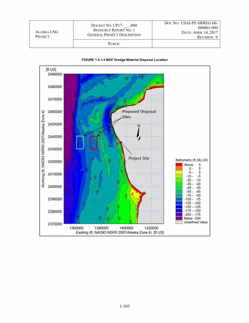
ALASKA LNG PROJECT
DOCKET NO. CP17-___-000 RESOURCE REPORT NO. 1
GENERAL PROJECT DESCRIPTION
DOC NO: USAI-PE-SRREG-00-000001-000
DATE: APRIL 14, 2017 REVISION: 0
PUBLIC
1-105
FIGURE 1.4.1-3 MOF Dredge Material Disposal Location

ALASKA LNG PROJECT
DOCKET NO. CP17-___-000 RESOURCE REPORT NO. 1
GENERAL PROJECT DESCRIPTION
DOC NO: USAI-PE-SRREG-00-000001-000
DATE: APRIL 14, 2017 REVISION: 0
PUBLIC
1-106
FIGURE 1.4.1-4 MOF Dredge Material Disposal Alternatives
1.4.2 Interdependent Project Facilities
1.4.2.1 Pipeline Facilities
1.4.2.1.1 ROW
Mainline
Typical construction ROW cross-section diagrams showing information such as widths and relative locations of existing ROWs, new ROW, and temporary construction ROW are provided in Appendix E. Table 1.4.2-1 provides the typical construction ROW configurations. For the Mainline, a permanent 53.5-foot-wide ROW would be acquired (50 feet plus pipe diameter). The construction ROW width would vary depending on the type of terrain, the season of construction, and the ease of access from nearby roads. The nominal construction ROWs level surface would be 110 feet wide, plus would include travel and bypass lanes where necessary. In addition, the construction footprint would be wider in areas where ATWS are required, such as at river or road crossings, side bends, and for cut/fill slope areas, as required. Any additional workspace would be restricted in areas of environmental or cultural sensitivity. A discussion of the rationale for the selection of pipeline ROW widths is presented in Appendix G.
The Mainline would be sited on land composed of more than 94 percent federal, state, borough, and municipal land of various holdings, with the remainder on privately owned land (see Resource Report No.

ALASKA LNG PROJECT
DOCKET NO. CP17-___-000 RESOURCE REPORT NO. 1
GENERAL PROJECT DESCRIPTION
DOC NO: USAI-PE-SRREG-00-000001-000
DATE: APRIL 14, 2017 REVISION: 0
PUBLIC
1-107
8). The offshore portion of the Mainline would be laid on the seafloor across Cook Inlet on state submerged and submersible lands. The construction ROW would be 13,200 feet wide to accommodate anchoring of the pipelay barge. The majority of the construction ROW for the offshore portion of the Mainline would not be disturbed during construction.
PBTL
A 120-foot-wide nominal construction ROW would be required for the PBTL (see typical ROW configuration in Appendix E). The PBTL would be installed on typical VSMs connected to a horizontal support member. A nominal 120-foot-wide ice road would be constructed along the construction ROW. In locations where additional laydown areas are needed, a wider construction ROW may be required. The VSM installation, pipeline assembly, and erection would be accomplished from the ice road. The PBTL would be located on State of Alaska land and following construction, a 100-foot-wide ROW would be acquired.
PTTL
The PTTL would be installed on typical VSMs connected to a horizontal support member. A 100-foot-wide nominal construction ROW would be required for the PTTL (Table 1.4.2-1; see typical ROW configuration in Appendix E). The width of the construction ROW would likely be wider in areas where additional workspace is required, such as at river crossings. Additional workspace would be restricted in areas of environmental or cultural sensitivity. The PTTL would be located on State of Alaska land and following construction, an 80-foot-wide ROW would be acquired.
TABLE 1.4.2-1
Typical Pipeline Construction Right-of-Way Configurations
Pipeline/Construction Area Construction Season
Nominal Construction Right-of-Way Width b (feet)
Right-of-Way Preparation
MAINLINE North of Brooks Range
Ice Work Pad Winter 145 Granular material or mineral soil work pad
Summer or Winter
140 (+cut/fill slope
areas)
Where required, additional 20 feet for travel lane would be added on working side and 15 feet for bypass lane added on spoil side.
Conventional a or cut and fill Summer or Winter
150 (+cut/fill slope
areas)
Where required, additional 20 feet for travel lane would be added on working side and 15 feet for bypass lane added on spoil side.
South of Brooks Range Frost packed Winter 110 Where required, additional 20 feet for travel lane
would be added on working side and 15 feet for bypass lane added on spoil side.
Granular material or mineral soil work pad
Summer or Winter
140 (+cut/fill slope
areas)
Where required, additional 20 feet for travel lane would be added on working side and 15 feet for bypass lane added on spoil side.
Conventional a or cut and fill Summer or Winter
150 (+cut/fill slope
areas)
Where required, additional 20 feet for travel lane would be added on working side and 15 feet for bypass lane added on spoil side.

ALASKA LNG PROJECT
DOCKET NO. CP17-___-000 RESOURCE REPORT NO. 1
GENERAL PROJECT DESCRIPTION
DOC NO: USAI-PE-SRREG-00-000001-000
DATE: APRIL 14, 2017 REVISION: 0
PUBLIC
1-108
TABLE 1.4.2-1
Typical Pipeline Construction Right-of-Way Configurations
Pipeline/Construction Area Construction Season
Nominal Construction Right-of-Way Width b (feet)
Right-of-Way Preparation
Matted Summer wetlands Summer 110 Using heavy timbers or similar Mountain cut only Summer 65
(+ATWS for pad on slope)
May require shoo-flies or access roads
Cook Inlet Ice-free period 13,200 Direct lay from lay vessel PBTL Ice Work Pad Winter 120 Built on VSMs PTTL
Ice Work Pad Winter 100 Built on VSMs ____________________ Notes: a Conventional preparation includes handling of organics material as detailed in the Applicant’s Procedures. b Right-of-way width excludes snow management areas. Snow will be blown off of the ROW, but no additional workspace will
be required for this activity.
1.4.2.1.2 Additional Temporary Workspace (ATWS)
ATWS would be located outside of, but adjacent to and contiguous with, the pipeline construction ROW where construction activities cannot be executed safely within the ROW or where more equipment may be necessary (e.g., waterbody, road, utility, and other crossings; at bends and timber storage locations; and in other situations,). Table 1.4.2-2 lists the typical sizes of ATWS that would be used for the Project. Each individual location requiring ATWS would be assessed and sized appropriately to account for terrain, soil conditions, site configuration, site-specific construction method, and construction season. Therefore, the exact dimensions of each ATWS may vary from those presented in Table 1.4.2-2. Typical ATWS that would be required for feature crossings are shown on typical drawings provided in Appendix E. Typical ATWS is included as part of the Project footprint depicted in Table 1.4.1-1. A description of the proposed ATWS is included in Appendix J.
TABLE 1.4.2-2
Typical ATWS Dimensions Associated with the Pipeline Facilities
Segment/ATWS Location Location Length (feet)
Width (feet)
MAINLINE Waterbody Crossings
Minor: Less than or equal to 10 feet wide (Summer and Winter)
Upstream/Workside 320 35 Downstream/Workside 320 35 Upstream/Spoilside 110 40 Downstream/Spoilside 110 40
Intermediate: Greater than 10 feet wide but less than or equal to 100 feet wide
Upstream/Workside 340 50 Downstream/Workside 340 50

ALASKA LNG PROJECT
DOCKET NO. CP17-___-000 RESOURCE REPORT NO. 1
GENERAL PROJECT DESCRIPTION
DOC NO: USAI-PE-SRREG-00-000001-000
DATE: APRIL 14, 2017 REVISION: 0
PUBLIC
1-109
TABLE 1.4.2-2
Typical ATWS Dimensions Associated with the Pipeline Facilities
Segment/ATWS Location Location Length (feet)
Width (feet)
Upstream/Spoilside 130 50 Downstream/Spoilside 130 50
Trenchless – Entry and Exit Points Specific to every Crossing 200 250 Trenchless – pipeline drag section false ROW (ROW used to assemble/weld the pipe string before inserting into drill hole)
Specific to every Crossing length of
crossing a 100
Road Crossings Bored
Upstream/Workside 270 50 Downstream/Workside 440 50 Upstream/Spoilside 180 50 Downstream/Spoilside 180 50
Open-Cut Upstream/Workside 80 35 Downstream/Workside 180 35 Upstream/Spoilside 65 35 Downstream/Spoilside 65 35
Utility crossings and or Third-Party pipelines Upstream/Workside 80 35 Downstream/Workside 180 35 Upstream/Spoilside 65 35 Downstream/Spoilside 65 35
Beginning or End of Construction Spread Workside 600 250 Timber Decks Workside 300 40 Horizontal Bends (>12 degrees)
Left Workside (one side of PI) 80 20 Right Workside (wrap around PI) 60 15
POINT THOMSON GAS TRANSMISSION LINE Waterbody Crossing
Minor: Less than or equal to 10 feet wide Aboveground N/A N/A Intermediate: Greater than 10-feet wide but less than or equal to 100 feet wide Aboveground N/A N/A
Major: Greater than 100 -feet wide Upstream 920 b 60 Downstream 700 b 60
Road Crossing
Primary-Secondary Road
Upstream/Workside 90 35 Downstream/Workside 90 35 Upstream/Spoilside 90 35 Downstream/Spoilside 90 35
Winter Trails; Trails; Access Roads; Unknown Aboveground N/A N/A Utility crossings and or Third-Party pipelines Aboveground N/A N/A Horizontal Bends
Left Aboveground N/A N/A Right Aboveground N/A N/A

ALASKA LNG PROJECT
DOCKET NO. CP17-___-000 RESOURCE REPORT NO. 1
GENERAL PROJECT DESCRIPTION
DOC NO: USAI-PE-SRREG-00-000001-000
DATE: APRIL 14, 2017 REVISION: 0
PUBLIC
1-110
TABLE 1.4.2-2
Typical ATWS Dimensions Associated with the Pipeline Facilities
Segment/ATWS Location Location Length (feet)
Width (feet)
____________________ Notes: a Dependent on crossing length of feature. b Average length of identified crossing.
The Project’s ATWS adjacent to the construction ROW (e.g., spoil storage areas) would vary depending on site-specific conditions. The estimated extent for travel lanes and bypass lanes is provided in Table 1.4.2-3 and is part of the ROW included in Table 1.4.2-1.
Travel lanes are needed to allow construction traffic to move along the ROW without interfering with the construction activities, as well as preventing construction activities from blocking traffic. Where easy access to the nearest existing public or private road exists, these lanes would likely not be needed. Travel lanes would be needed in locations where there are no access roads approximately every 2 to 3 miles.
In addition to travel lanes, bypass lanes would also be required when the spoil side of the ROW (i.e., location of excavated material) is next to the main access (e.g., Dalton Highway). Construction traffic reaching the ROW from that spoil side could be blocked from accessing the work side of the ROW or the travel lane by an open ditch or a welded pipe string. Use of the bypass lane would allow traffic to proceed parallel to the ROW until the next open “crossing” of the pipeline centerline before pipe is strung or the ditch excavated.
TABLE 1.4.2-3
Estimated Extent of Travel Lanes and Bypass Lanes
Spread Section From MP To MP Total
Limited Access (miles)
Travel Lane (miles)
Bypass Lane
(miles)
Access Road on
Travel Lane (miles)
1
A 0.00 56.63 56.63 56.63 56.63 0.00
B 56.63 63.33 6.70 6.70 0.00 0.00
B 94.31 109.65 15.34 15.34 0.00 0.00
C 129.58 136.52 6.94 6.94 0.00 0.00
2
A 223.47 224.27 0.80 0.80 0.00 0.00
A 227.71 228.09 0.38 0.38 0.00 0.00
L 389.00 393.95 4.95 4.95 0.00 0.00
3
A 401.20 408.10 6.90 6.90 6.90 6.90
B 408.10 421.51 13.41 0.00 0.00 13.41
C 430.48 464.36 33.88 33.88 33.88 0.00
C 464.36 470.70 6.34 0.00 6.34 0.00
E 473.78 489.38 15.60 15.60 15.60 0.00

ALASKA LNG PROJECT
DOCKET NO. CP17-___-000 RESOURCE REPORT NO. 1
GENERAL PROJECT DESCRIPTION
DOC NO: USAI-PE-SRREG-00-000001-000
DATE: APRIL 14, 2017 REVISION: 0
PUBLIC
1-111
TABLE 1.4.2-3
Estimated Extent of Travel Lanes and Bypass Lanes
Spread Section From MP To MP Total
Limited Access (miles)
Travel Lane (miles)
Bypass Lane
(miles)
Access Road on
Travel Lane (miles)
F 489.38 498.58 9.20 9.20 0.00 0.00
K 538.87 543.08 4.21 4.21 0.00 0.00
4
A 642.28 648.28 6.00 6.00 0.00 0.00
B 674.05 693.94 19.89 0.00 0.00 19.89
B 693.94 703.80 9.86 0.00 0.00 9.86
C 703.80 721.23 17.43 17.43 0.00 0.00
C 721.23 745.00 23.77 23.77 0.00 0.00
Totals 258.23 208.73 119.35 50.06
1.4.2.2 Pipeline Aboveground Facilities
Land requirements for the Project’s Pipeline Aboveground Facilities are summarized as follows.
1.4.2.2.1 Compressor Stations
The Project design anticipates construction of eight compressor stations. Compressor station layouts are designed to accommodate both permanent operation facilities and temporary construction facilities (construction camp and laydown areas) within the same plot, which would be permanently fenced. Land requirements for compressor stations are provided in Table 1.4-1.
1.4.2.2.2 Heater Station
The heater station layout would be designed to accommodate permanent operation facilities and temporary construction facilities (construction camp and laydown areas) within the same plot, which would be permanently fenced. Land requirements for the heater stations are provided in Table 1.4-1.
1.4.2.2.3 Meter Stations
The meter stations would be located within the footprint of the other facilities (e.g., Liquefaction Facility, GTP, and PTU) such that no additional land requirements would be necessary beyond those already associated with construction of the other facilities.
1.4.2.2.4 MLBVs
Construction and operation of the MLBVs would take place within the pipeline ROW, compressor stations, heater station, and other facilities. Therefore, with the potential exception of access requirements, no additional land use would occur beyond those already associated with construction of the other facilities. Isolated MLBVs would be approximately 0.4 acre in size and would be fenced.

ALASKA LNG PROJECT
DOCKET NO. CP17-___-000 RESOURCE REPORT NO. 1
GENERAL PROJECT DESCRIPTION
DOC NO: USAI-PE-SRREG-00-000001-000
DATE: APRIL 14, 2017 REVISION: 0
PUBLIC
1-112
Helipads (see Appendix F) would be required for those MLBVs outside of a compressor station site. However, they would be sited within the pipeline ROW.
1.4.2.2.5 Launchers and Receivers
Construction and operation of launchers and receivers would generally occur within a proposed aboveground facility site (e.g., compressor stations, GTP, and Liquefaction Facility) such that no additional land requirements would be necessary beyond those already associated with construction of the other facilities.
1.4.2.2.6 Gas Interconnection Points
Construction of a gas interconnection point would occur within the pipeline ROW. Therefore, no additional land use associated with the Project would be required beyond the construction ROW.
1.4.2.2.7 Cathodic Protection Facilities
Land requirements for the cathodic protection facilities would primarily be within the pipeline ROW or a compressor station site where practical. Test lead posts would also be located along the permanent pipeline ROW. The requirement for any additional land use associated with the cathodic protection facilities is currently under evaluation.
1.4.2.3 Pipeline Associated Infrastructure
The following sections discuss the land requirements for Pipeline Associated Infrastructure related to both the pipelines and aboveground facilities. The Project representatives would take an integrated approach to minimize the overall Project footprint as practicable.
1.4.2.3.1 Access Roads
A list and description of access roads and shoo-flies that would be used by the Project are included in Appendix F and depicted on the maps in Appendix A. In areas, north of Livengood, construction crews and operations staff would use existing granular material access roads that were built for TAPS and for the Dalton Highway, where appropriate.
South of Livengood, the design is based on access from the nearest existing public or private road to the construction ROW where possible. This access would include improvements to existing roads (e.g., widening, granular material fill, culverts, reduce curvature of the road) or construction of new roads. For winter construction, access roads would be made of ice or granular material, depending on location and season.
Shoo-fly roads would be required where traffic access is not possible along the ROW due to severe slopes or other impediments. The shoo-flies would allow traffic to detour around the steep slope sections and maintain access along the ROW.

ALASKA LNG PROJECT
DOCKET NO. CP17-___-000 RESOURCE REPORT NO. 1
GENERAL PROJECT DESCRIPTION
DOC NO: USAI-PE-SRREG-00-000001-000
DATE: APRIL 14, 2017 REVISION: 0
PUBLIC
1-113
1.4.2.3.2 Helipads
Helipads would be constructed with dimensions of approximately 150 feet by 150 feet. The affected land most likely would be within a construction camp site and/or the permanent operations ROW of the pipeline or a compressor station (see Table 1.3.5-1). If so, no additional land requirements would be necessary beyond those already associated with construction of the other facilities. After construction, the land would be reclaimed as per landowner requirements.
1.4.2.3.3 Airstrips
At this time, there are no major upgrades that may be required for existing public airports or private airfields (See Table 1.3.6-1 for a list of potential minor upgrades required).
1.4.2.3.4 Construction Camps, Pipe Storage Areas, Contractor Yards, and Rail Spurs
Temporary construction camps, pipe storage yards, and contractor yards would be built at various locations to support pipeline construction (see Appendices A and J). In general, construction camps would range in size depending on the number of workers housed there. Pipe storage yards would be spaced approximately every 20 miles along or near the pipeline construction ROW. Appendix E provides typical drawings and the range of sizes for camps, pipe storage, and contractor yards. In some cases, a pipe yard and contractor yard may be collocated together and/or with a construction camp, depending on available acreage, access, and topography. To the extent practical, these sites would be located on previously disturbed areas. Construction camps would be located such that they take into consideration the travel distance from camp to construction site, the duration the camp would remain in the same location, the design occupancy, available water sources, and available pre-existing disturbed areas.
During post-construction reclamation, temporary camps, pipe storage areas, and contractor yards would be disassembled and surface facilities removed unless other arrangements are made with the landowner or land managing agency. Granular material pads installed as part of camp or yard construction would be left in accordance with land use agreements.
The Mainline MOF on the west side of Cook Inlet will be further developed and the size of land required on and offshore will be provided as available.
1.4.2.3.5 Material Sites
In general, a material site would be required approximately every 5 to 15 miles of pipeline ROW to support construction. Potential granular material locations are being evaluated. A list of potential sites that could be used is provided in the Project’s Gravel Sourcing Plan and Site Reclamation Measures which is included in Resource Report No. 6, Appendix F.
1.4.2.4 GTP
Approximately 956 acres would be affected during construction of the GTP. Of the approximately 956 acres, operations would require approximately 789 acres (none of which are offshore). The acreage for the

ALASKA LNG PROJECT
DOCKET NO. CP17-___-000 RESOURCE REPORT NO. 1
GENERAL PROJECT DESCRIPTION
DOC NO: USAI-PE-SRREG-00-000001-000
DATE: APRIL 14, 2017 REVISION: 0
PUBLIC
1-114
GTP would accommodate the associated infrastructure necessary to construct, assemble, and operate the GTP.
1.4.2.4.1 GTP Pad and Operations Center Pad
The GTP Pad would be built using granular material to protect the tundra and permafrost and would require approximately 228 acres of land. The Operations Center Pad would be separate from the GTP Pad, and would include area for the Integrated Construction and Operations Camp along with some construction laydown area. Land required for this pad would impact approximately 56 acres and is expected to be used during construction and operation.
1.4.2.4.2 GTP Associated Infrastructure
GTP Associated Pipelines
The fuel gas and propane pipelines would be installed on the same VSM as the PBTL and share the same construction and operational ROWs (see Table 1.4.2-1). The water line from the reservoir to the GTP is above ground and would be installed on a VSM connected to a horizontal support member. An approximately 110-foot-wide nominal construction and 100-foot-wide ROW would be required for the new water supply pipeline.
ROW maintenance would occur during scheduled pipeline maintenance. Scheduled pipeline maintenance would be conducted during the winter, with access by foot or suitable low pressure type vehicle. Major maintenance would require an ice road be built alongside the pipeline (between the granular material road and pipeline).
Module Staging Area
Land required for the material module staging area would be approximately 86 acres during construction.
West Dock Modifications
Construction of the GTP would require a dock facility at Prudhoe Bay capable of receiving large modules for construction on the North Slope. Installation of the DH 4 facilities would require granular material fill to create a dock head of approximately 31 acres.
The proposed DH 4 design does not require dredging a navigation channel. The proposed DH 4 location/size/orientation is based on preliminary navigational requirements, PBU interface discussions, and currently available field data. Although very recent bathymetric survey data (2016) was used for DH 4 placement, the seafloor will continue to change by sediment erosion/deposition up until construction, which may require adjustments. Based on the development of this and similar items, the DH 4 location/size/orientation may require updates during future Project phases.
Barge Bridge
Dredging is not planned at the proposed barge bridge at this time.

ALASKA LNG PROJECT
DOCKET NO. CP17-___-000 RESOURCE REPORT NO. 1
GENERAL PROJECT DESCRIPTION
DOC NO: USAI-PE-SRREG-00-000001-000
DATE: APRIL 14, 2017 REVISION: 0
PUBLIC
1-115
Water Reservoir
The water reservoir is expected to cover approximately 35 acres, with a nominal depth of approximately 35–55 feet.
GTP Access Roads
Workers would use existing, modified, and new roads to access the GTP site from West Dock (see Appendix F). A total of approximately 258 acres of land would be used during construction and operation of access roads associated with the GTP. This acreage includes the new section of causeway that parallels the existing causeway between DH 3 and DH 4, widening the existing causeway road from the DH 3, widening and extending an existing haul road in the PBU, and constructing new access roads to the mine and reservoir sites as well as the access road to the PBU CGF.
Construction Camps
Pioneer Camp
A Pioneer Camp would be established to support development of construction infrastructure during GTP construction, including granular material mine operations and construction of access roads, granular material pads, water reservoir, VSMs, and pipelines. A specific location for the Pioneer Camp has not been identified at this stage of the Project design but is expected to be within the PBU or Deadhorse. The Pioneer Camp would require approximately 15 to 30 acres of land.
Temporary Construction and Permanent Operations Camp
An onsite Integrated Construction and Operations Camp would be constructed to support Project construction. The onsite construction camp would be located entirely within the GTP Operations Center Pad acreage and would remain as a permanent operations camp (see Section 1.3.2.8.11.1).
Material Sites
The sand and granular material required for construction of the GTP and related facilities would be obtained from a new material sites, the water reservoir, and an existing material site, if available to the Project. The new granular material mine would span up to approximately 141 acres. Additional details are provided in the Project’s Gravel Sourcing Plan and Site Reclamation Measures, located in Resource Report No. 6, Appendix F.
1.5 CONSTRUCTION SCHEDULE, PROCEDURES, AND WORKFORCE
1.5.1 Project Construction Schedule
The Project representatives intend to request that FERC issue authorization to site, construct, and operate the Project no later than late 2018, with construction to most likely commence late 2019. It is anticipated that construction and commissioning of the facilities would take approximately eight years to complete. Construction activities would be divided into phases. The first phase is planned to last from 2019–2025

ALASKA LNG PROJECT
DOCKET NO. CP17-___-000 RESOURCE REPORT NO. 1
GENERAL PROJECT DESCRIPTION
DOC NO: USAI-PE-SRREG-00-000001-000
DATE: APRIL 14, 2017 REVISION: 0
PUBLIC
1-116
and would include construction related to the first LNG and GTP trains, marine facilities, Mainline, PBTL, and PTTL, resulting in first production of LNG. After 2025, the installation of the remaining Project facilities needed for full production would take place. Table 1.5.1-1 summarizes the planned Project schedule.
TABLE 1.5.1-1
Project Schedule Major Milestone Start Date End Date Application Submittal 4Q 2016 Anticipated Draft EIS 4Q 2016 4Q 2017 Anticipated Final EIS 4Q 2017 2Q 2018 Anticipated FERC Order 3Q 2018 Anticipated FERC Notices to Proceed for Construction Start 3Q 2019 1Q 2020 LNG Facility Construction Infrastructure Development (Camps, Granular Material, Access, etc.) 4Q 2019 2Q 2022 Site Preparation Activities, Commence Piling and Equipment Concrete Foundations 1Q 2020 3Q 2023 Commence LNG Tank Construction 2Q 2021 4Q 2024 Installation and Interconnection of Train 1 and 2 Modules and Equipment, Power and Utilities 2Q 2022 2Q 2025 Mechanical Complete of Train 1, Power and Utilities. LNG Product Loading (Trestle) Mechanically Complete. Installation and Interconnection of Train 2 and 3 Modules/Equipment. Commence Pre-Commissioning.
1Q 2024 3Q 2025
Train 2 and Train 3 Mechanically Complete 1Q 2025 4Q 2025 LNG Train 1 Commissioning and Start-up (with GTP Train 1 Gas) 3Q 2024 4Q 2025 LNG Train 2 Commissioning and Start-Up (with GTP Train 1 Gas) 4Q 2025 1Q 2026 LNG Train 3 Commissioning and Start-Up (with GTP Train 2 Gas) 2Q 2026 3Q 2026 Kenai Spur Highway Relocation 1Q2019 1Q2020 Marine Terminal Site Preparation Activities, MOF Construction 4Q 2019 2Q 2021 Dredging, Complete MOF 1Q 2021 2Q 2021 Commence Installation of Trestle and Berths, Quadropod Installation 1Q 2022 4Q 2022 Complete Installation of Trestle, Continue Installation of Berths, Commence Installation of PLF Modules, Berths, and Mooring Dolphins 1Q 2023 4Q 2023
Complete Installation of PLF 1Q 2024 4Q 2024 MOF Reclamation/Demobilization 3Q 2026 3Q 2027 GTP Construction Infrastructure Development (Camps, Granular Material, Access, Etc.) 3Q 2019 1Q 2023 Site Preparation Activities and Field Erected Equipment Delivery/Setting 4Q 2019 2Q 2023 Sealift # 1 Offload/Set Modules 3Q 2023 3Q 2023 Install Plant Utilities, Flares and Flare Pipe-Racks 3Q 2023 1Q 2024 Make Utility Interconnects and Start-Up 1Q 2024 2Q 2024 Sealift # 2 Offload/Set Modules 3Q 2024 3Q 2024 Install Train 1 and Propane Modules and Make Interconnects 3Q 2024 1Q 2025 Commissioning and Start-Up Train 1 and Propane Refrigeration 4Q 2024 2Q 2025

ALASKA LNG PROJECT
DOCKET NO. CP17-___-000 RESOURCE REPORT NO. 1
GENERAL PROJECT DESCRIPTION
DOC NO: USAI-PE-SRREG-00-000001-000
DATE: APRIL 14, 2017 REVISION: 0
PUBLIC
1-117
TABLE 1.5.1-1
Project Schedule Sealift # 3 Offload/Set Modules 3Q 2025 3Q 2025 Install Train 2 and Make Interconnects 3Q 2025 1Q 2026 Commissioning and Start-Up Train 2 4Q 2025 2Q 2026 Sealift # 4 Offload/Set Modules 3Q 2026 3Q 2026 Install Train 3 and Make Interconnects 3Q 2026 1Q 2027 Commissioning and Start-Up Train 3 4Q 2026 2Q 2027 PBTL Construction Install VSMs and Supports 1Q 2022 3Q 2022 Pipeline Construction 1Q 2022 3Q 2023 Hydrostatic test and Final Tie-In 3Q 2023 3Q 2022 Mainline Spread 1 Construction Infrastructure Development (Camps, Borrow Sites, Access and Pads) 2Q 2020 4Q 2022 Site Preparation Activities (ROW Construction) 2Q 2021 3Q 2023 Pipeline Construction 4Q 2022 4Q 2024 Hydrostatic test and Final Tie-In (Summer months only) 2Q 2023 4Q 2024 Spread 2 Construction Infrastructure Development (Camps, Borrow Sites, Access and Pads) 2Q 2020 4Q 2022 Site Preparation Activities (ROW Construction) 4Q 2020 4Q 2022 Pipeline Construction 4Q 2022 4Q 2024 Hydrostatic test (Summer months only) and Final Tie-In 2Q 2023 4Q 2024 Spread 3 Construction Infrastructure Development (Camps, Borrow Sites, Access and Pads) 2Q 2020 3Q 2022 Site Preparation Activities (ROW Construction) 3Q 2020 3Q 2022 Pipeline Construction 4Q 2021 4Q 2023 Hydrostatic test (Summer months only) and Final Tie-In 2Q 2022 4Q 2023 Spread 4 Construction Infrastructure Development (Camps, Borrow Sites, Access and Pads) 2Q 2020 4Q 2022 Site Preparation Activities (ROW Construction) 4Q 2020 1Q 2023 Pipeline Construction 4Q 2021 4Q 2023 Hydrostatic test (Summer months only) and Final Tie-In 2Q 2022 4Q 2023
Aboveground Mainline Facilities Constructiona Sagwon Compressor Station 2Q 2025 2Q 2026 Galbraith Lake Compressor Station 2Q 2024 2Q 2025 Coldfoot Compressor Station 2Q 2025 2Q 2026 Ray River Compressor Station 2Q 2023 2Q 2024 Minto Compressor Station 2Q 2024 2Q 2025 Healy Compressor Station 2Q 2023 2Q 2024 Honolulu Creek Compressor Station 2Q 2025 2Q 2026 Rabideux Creek Compressor Station 2Q 2024 2Q 2025 Theodore Heater Station 2Q 2023 2Q 2024

ALASKA LNG PROJECT
DOCKET NO. CP17-___-000 RESOURCE REPORT NO. 1
GENERAL PROJECT DESCRIPTION
DOC NO: USAI-PE-SRREG-00-000001-000
DATE: APRIL 14, 2017 REVISION: 0
PUBLIC
1-118
TABLE 1.5.1-1
Project Schedule Point Thomson Meter Station 1Q 2024 1Q 2025 GTP/Mainline Meter Station 1Q 2024 1Q 2025 Nikiski Meter Station 1Q 2024 1Q 2025 Fill Main Pipeline and Commissioning/Start-up Facilities (with GTP Gas) 2Q 2024 3Q 2025 Offshore (Cook Inlet) Spread Offshore Pipeline Construction 2Q 2022 1Q 2023 Hydrostatic test and Final Tie-In 2Q 2023 3Q 2023 PTTL Spread 1 Construction Infrastructure Development (Ice Road Construction) 4Q 2022 1Q 2023 Site Preparation Activities (ROW Construction) 4Q 2022 1Q 2023 Pipeline Construction 4Q 2022 1Q 2023 Hydrostatic test and Final Tie-In 2Q 2023 3Q 2023 Spread 2 Construction Infrastructure Development (Ice Road Construction) 4Q 2022 1Q 2023 Site Preparation Activities (ROW Construction) 4Q 2022 1Q 2023 Pipeline Construction 4Q 2022 1Q 2023 Hydrostatic test and Final Tie-In 2Q 2023 3Q 2023 Project Commissioning/In-Service First LNG Product, Train 1 Start-up 3Q 2024 4Q 2025 Intermediate LNG Product, Train 2 Start-Up 1Q 2026 Full LNG Product, Train 3 Start-Up 3Q 2027 ____________________ a The construction schedule for compressor stations and the heater station is preliminary and subject to further optimization. Note: Construction Quarters (Q) 1Q = Jan-01 to Mar-31; 2Q = Apr-01 to June-30; 3Q = Jul-01 to Sept-30; 4Q = Oct-31 to Dec-31
1.5.1.1 Liquefaction Facility Construction Schedule
Liquefaction Facility site preparation would commence after acquisition of necessary property rights, permits, and authorizations, and construction would generally proceed as follows:
Site preparation activities (e.g., clearing, grubbing) and infrastructure development would begin in the first quarter of 2020 and are planned to occur over a two-year period, along with MOF construction, trestle/PLF substructure installation, and site cut and fill work;
A significant number of the major facilities for the LNG Plant would be built as modules off site and delivered by vessel from 2021 through 2024. Other major facilities would be “stick-build” (i.e., constructed fully on site) at the LNG Plant itself. Stick-build facilities, including the LNG storage tanks, would be erected at the site over the course of three to four years; and

ALASKA LNG PROJECT
DOCKET NO. CP17-___-000 RESOURCE REPORT NO. 1
GENERAL PROJECT DESCRIPTION
DOC NO: USAI-PE-SRREG-00-000001-000
DATE: APRIL 14, 2017 REVISION: 0
PUBLIC
1-119
Commissioning of the tanks and processing units would occur as natural gas is delivered to the site.
1.5.1.2 Mainline Construction Schedule
Mainline site preparation would commence after acquisition of necessary property rights, permits, and authorizations. Pipeline work would be divided among a number of different construction spreads determined based on logistics, construction, and other planning considerations. Construction would generally proceed as follows:
The Mainline infrastructure construction and logistical support is planned to begin during 2020. One to three years of infrastructure construction and ROW clearing would take place before primary pipeline construction activities begin. The construction of the Mainline is planned to occur over a two- to three-year period using a number of different construction spreads in winter and summer seasons;
The offshore portion of the Mainline across Cook Inlet would be laid in the ice-free season. The Project representatives would plan to avoid conflicts with other waterway and nearshore users to the extent practicable, including commercial, subsistence, and recreational vessels and activities (see Resource Report No. 5). Hydrostatic testing would occur shortly after installation; and
Aboveground facilities (e.g., compressor stations, meter stations, heater station, and other associated pipeline infrastructure) would also be constructed per Table 1.5.1-1.
1.5.1.3 GTP Construction Schedule
GTP site preparation would commence after acquisition of necessary property rights, permits, and authorizations, and construction would generally proceed as follows:
The Pioneer construction camp would be established at or near Deadhorse or the PBU in the winter of 2019;
Additional infrastructure construction activities are planned to start in the winter of 2019. The majority of this work would be associated with mine/reservoir overburden removal and granular mining, and construction of granular pads and access roads to support the aboveground facility construction efforts as well as construction of the mine site and water reservoir;
Major components of the GTP would be built as modules off site and delivered in a series of sealifts. Four consecutive summer sealift seasons and corresponding construction periods are planned. As installation of the trains is completed each year, the facilities would be released to the facility operations team for commissioning and start-up;
Due to the size of the modules required for the GTP, large oceangoing vessels would be used; and
In total, construction for the GTP facility would last eight years.
ALASKA LNG PROJECT
DOCKET NO. CP17-___-000 RESOURCE REPORT NO. 1
GENERAL PROJECT DESCRIPTION
DOC NO: USAI-PE-SRREG-00-000001-000
DATE: APRIL 14, 2017 REVISION: 0
PUBLIC
1-120
1.5.1.4 PBTL and PTTL Construction Schedule
Site preparation for the PBTL and PTTL would commence after acquisition of necessary property rights, permits, and authorizations. Construction work on the PTTL is scheduled to commence in the 2022–2023 timeframe and take approximately one to two years to complete.
The PBTL would be constructed concurrent with the GTP construction and take approximately one year to complete.
1.5.1.5 Non-jurisdictional Facilities Construction
Site preparation for the PTU modification/new facilities would commence after acquisition of necessary permits and authorizations. Construction is anticipated to be conducted over approximately four years beginning in year three of the proposed Project with construction completed in year seven. Drilling would begin in year five of the proposed Project and be completed in year eight. Initial activities would include mobilization of camp and construction equipment, as well as mining, conditioning, and placement of granular material. Gathering lines would be installed. Modules fabricated off- site would be mobilized to site via truck and sealift. The modules arriving by barge would be moved to shore using a barge bridge. The modules would then be installed and commissioned.
The PBU MGS project would begin construction in year two of the proposed Project and would be completed in year six. Drilling would begin in year six of the proposed Project and be completed in year 10.
Relocation of the Kenai Spur Highway is planned to be completed before construction of the Liquefaction Facility begins to minimize disruption to community traffic requirements.
1.5.2 Project Construction Procedures
Except where otherwise authorized, the proposed facilities would be designed and constructed in accordance with applicable federal, state, and local regulations, permits, and industry-recognized standards. Applicable federal regulations that apply to some or all of the facilities included as a part of this Project include 49 C.F.R. Part 193, Liquefied Natural Gas Facilities: Federal Safety Standards; 49 C.F.R. Part 192, Transportation of Natural Gas and Other Gas by Pipeline: Minimum Federal Safety Standards; 18 C.F.R. § 2.69, Guidelines To Be Followed by Natural Gas Pipeline Companies in the Planning, Clearing and Maintenance of Rights-of Way and the Construction of Aboveground Facilities; 33 C.F.R Part 127, Waterfront Facilities handling Liquefied Natural Gas and Liquefied Hazardous Gases; and American Society of Mechanical Engineers’ Process Piping (ASME B31.3). Any modifications to the provisions of the 49 C.F.R. Part 192 regulations would be addressed through PHMSA special permits in accordance with 49 C.F.R. Part 190.341, Pipeline Safety Enforcement and Regulatory Procedures.
Alaska presents unique and challenging Arctic construction and operating conditions. The oil and gas industry has successfully operated in this environment since the late 1970s. As a result, modified procedures would be proposed where the measures contained in the FERC Upland Erosion Control,
Revegetation, and Maintenance Plan (FERC Plan) and Wetland and Waterbody Construction and
Mitigation Procedures (FERC Procedures) are not considered applicable, are technically infeasible, or are

ALASKA LNG PROJECT
DOCKET NO. CP17-___-000 RESOURCE REPORT NO. 1
GENERAL PROJECT DESCRIPTION
DOC NO: USAI-PE-SRREG-00-000001-000
DATE: APRIL 14, 2017 REVISION: 0
PUBLIC
1-121
unsuitable due to Alaska conditions. The Project representatives have prepared and would implement a Project-specific Upland Erosion Control, Revegetation, and Maintenance Plan (Applicant’s Plan,
Appendix D of Resource Report No. 7) and Wetland and Waterbody Construction and Mitigation
Procedures (Applicant’s Procedures, Appendix N of Resource Report No. 2). The Applicant’s Plan and Applicant’s Procedures have been developed using the 2013 versions of the FERC Plan and FERC Procedures as a basis. The Applicant’s Plan and Procedures have been based upon the FERC Plan and FERC Procedures and applicable permit conditions using known Alaska or Arctic best management practices (BMPs) consistent with the FERC guidance. In addition, a Project-specific Winter and Permafrost
Construction Plan has been prepared and is an appendix to this Resource Report.
Mitigation plans are listed in their respective resource report. A brief description of some of these plans are noted below:
The Avian Protection Plan describes the procedures that would be followed during Project construction for avian protection following the guidelines established by the Avian Power Line Interaction Committee and the USFWS (see Resource Report No. 3). The Project will follow, to the extent practicable, the most recent guidance from USFWS, Region 7 regarding the recommended time periods to avoid vegetation clearing. In general, clearing of the construction ROW will occur in the winter prior to a particular construction season. Alaska LNG will work with the USFWS on other means to avoid impacts or remove habitat if clearing is required during the nesting season
The Blasting Plan describes the measures that would be taken during Project construction to ensure that blasting operations are safely carried out in accordance with the manufacturers’ prescribed safety measures; in compliance with applicable federal, state, and local regulations; and prevent damage to natural resources or otherwise jeopardize public safety (see Resource Report No. 6).;
The Construction Unanticipated Discoveries Plan for Cultural Resources and Human Remains describes the procedures to be used in the event that previously unreported historic properties or human remains are found during construction of the Project (see Resource Report No. 4);
The Fugitive Dust Control Plan describes the procedures that would be used to minimize fugitive dust during Project construction (see Resource Report No. 9);
The Gravel Sourcing Plan and Reclamation Measures describes the material requirements, sources, extraction protocols, transportation logistics, and reclamation measures during the construction and reclamation phases of the Project (see Resource Report No. 6);
The Horizontal Directional Drill (HDD) Inadvertent Release Contingency Plan describes the procedures that would be followed should an inadvertent fluid release occur during HDD activities (see Resource Report No. 2);
The Project Waste Management Plan describes the procedures that would be followed for managing hazardous and non-hazardous solid and liquid wastes generated by the proposed Project (see Resource Report No. 8);

ALASKA LNG PROJECT
DOCKET NO. CP17-___-000 RESOURCE REPORT NO. 1
GENERAL PROJECT DESCRIPTION
DOC NO: USAI-PE-SRREG-00-000001-000
DATE: APRIL 14, 2017 REVISION: 0
PUBLIC
1-122
The Noxious/Invasive Species Control Plan describes preventative and control measures that would be used to avoid or minimize the spread of noxious weeds during the construction and reclamation phases of the Project (see Resource Report No. 3);
The North Slope Activities: Polar Bear and Pacific Walrus Avoidance and Interaction Plan
describes the avoidance, early detection, and deterrence procedures that would be implemented during construction of the Project (see Resource Report No. 3);
The Paleontological Resources Unanticipated Discoveries Plan discusses the procedures that would be used to reduce the potential for damage in the event that significant unanticipated paleontological resources were encountered during construction of the Project (see Resource Report No. 4);
The SPCC Plan describes the management procedures for the prevention of releases of fuels, lubricants, and coolants, as well as potentially hazardous materials, that would be implemented during construction of the Project (see Resource Report No. 2);
The Stormwater Pollution Prevention Plan describes the potential sources of pollution that may reasonably be expected to affect the quality of stormwater discharges from Project construction, describes the practices that would be used to reduce the pollutants in stormwater discharges, and assures compliance with the terms and conditions of the Alaska Construction General Permit (see Resource Report No. 2);
The Timber Management Plan describes the timber removal protocols, including those for salvage timber, that would be used during construction of the Project (see Resource Report No. 8);
The Unanticipated Contamination Plan describes the processes that would be followed by the Project in the event of finding undocumented or anticipated contaminated material during construction of the Project (see Resource Report No. 8);
The Lighting Plan describes the measures that would be followed by the Project to provide adequate lighting for the prevention of accidents and compliance with Occupational Safety and Health Administration (OSHA) requirements while reducing visible light disturbance to the public and wildlife, as practicable, and reduce the potential for light pollution, including backscatter into the sky (see Resource Report No. 8); and
The Traffic Mitigation Plan describes the measures that would be implemented to mitigate for potential traffic impedance during construction (see Resource Report No. 8).
1.5.2.1 Construction Logistics
Logistics activities include the transporting of personnel, equipment, construction materials, camps, and supplies to construction sites via sea, road, rail, and/or air transportation infrastructure. Although site preparation and construction would be phased to lessen impacts to local infrastructure and communities, the size of this Project and duration of construction would require detailed planning with state and local

ALASKA LNG PROJECT
DOCKET NO. CP17-___-000 RESOURCE REPORT NO. 1
GENERAL PROJECT DESCRIPTION
DOC NO: USAI-PE-SRREG-00-000001-000
DATE: APRIL 14, 2017 REVISION: 0
PUBLIC
1-123
agencies to reduce impacts to existing infrastructure. Logistics activities would begin prior to Project infrastructure construction subject to necessary regulatory approvals. The Project representatives are evaluating opportunities to further consolidate and/or coordinate facilities and activities, where practicable.
The majority of materials and equipment would be unloaded and enter Alaska through the following points of entry:
The Port of Anchorage – Barge and vessel routes; The Port of Seward – Barge and vessel routes; The Port of Whittier – Barge routes; The Port of Valdez – Barge and vessel routes; ALCAN Highway U.S.–Canada border crossing – Trucking routes; Direct delivery to the Mainline MOF, Liquefaction Facility MOF, and West Dock.
After construction, it is anticipated that equipment that was brought to Alaska by construction contractors would be demobilized back to its respective point of origin.
A detailed discussion on the existing conditions of Alaska’s transportation infrastructure and potential impacts related to Project construction and operations is provided in Resource Report No. 5. A brief overview of the predominant transportation modes in Alaska anticipated for the Project is provided in the following section. Even without the Mainline route passing through Fairbanks, the Fairbanks area would serve as a logistics hub for Project construction activities given its central location in the state and existing transportation infrastructure (i.e., highway, railroad, and air).
It is anticipated that a major hub for moving materials from the Lower 48 states would be through the Ports of Seattle and Tacoma on the West Coast. Other key ports are anticipated to be Houston, Texas, and Panama City, Florida. In addition, the Seattle-Tacoma International Airport would likely be a personnel hub and collection point for other Lower 48 and international labor pools for consolidated transportation to Alaska.
Based on the results of current engineering studies and discussions with potential vendors and contractors regarding the logistics associated with construction of the Project, there may be additional work required to upgrade existing facilities in Alaska to build, store, and transport the pipe, modules, turbines, and equipment. The extent of the work required is under evaluation, as well as the responsible permitting party (if any permits are required), for this additional work.
1.5.2.1.1 Transportation Modes
Marine Transportation
The main method for marine transportation of construction materials would be through the use of break bulk and container vessels, however tugs/barge and heavy lift Ro/Ro vessels would also be used. The Project would require the use of multiple, existing ports in Southcentral Alaska for both vessel offloading, storage, and docking including:
Port of Anchorage – The Port of Anchorage is located at the head of Cook Inlet, approximately 180 miles north of the ocean entrance to the Gulf of Alaska. Cook Inlet provides navigable, year-

ALASKA LNG PROJECT
DOCKET NO. CP17-___-000 RESOURCE REPORT NO. 1
GENERAL PROJECT DESCRIPTION
DOC NO: USAI-PE-SRREG-00-000001-000
DATE: APRIL 14, 2017 REVISION: 0
PUBLIC
1-124
round access to the Port, which is commercially served with intermodal rail access to Fairbanks, and road access that connects to Fairbanks, Nikiski, and the North Slope. Anchorage would be the predominant point of entry for most of the Project's general freight (i.e., non-modularized items). Once received at the Port, the materials would be deployed outward from Anchorage via rail, truck, and barge;
Port of Seward – The Port of Seward is an ice-free port located in Resurrection Bay opening to the Gulf of Alaska and the Great Circle Route. The Port has an ARRC dock rail that connects to Anchorage, Fairbanks, and southern sections of the Mainline corridor south of Fairbanks. Road access connects the Port of Seward to Nikiski, Anchorage, Fairbanks, and the North Slope. The Port of Seward would be used primarily by the Project for the receipt of pipe; and
Port of Whittier – The Port of Whittier is located in Prince William Sound and it is the only port in Alaska that is able to accept rail barge operations. Whittier is connected to the Alaska road and rail system by the 2.5-mile-long Anton Anderson Memorial Tunnel. The snowfall and accumulation in the area can negatively impact marine operations and productivity. The Port of Whittier would be used by the Project primarily for containerized cargo, pipe, and fuel.
Additional sites such as the Port of Homer, Offshore Systems Kenai dock, or other industrial areas in the port area of Kenai, north of the Liquefaction Facility site, may also be used in a limited capacity by the Project until the temporary, onsite MOF is developed to support construction of the Liquefaction Facility.
The Project could potentially use Port MacKenzie as a distribution center for the concrete coated offshore pipe. Port MacKenzie is located near the mouth of Knik Arm in Cook Inlet, directly north of Anchorage. Further potential use of the port would be dependent upon the completion of the ARRC rail spur.
The Project could potentially use the Port of Valdez as an alternative port for receiving truckable modules, and other materials with destinations in Fairbanks and north of Fairbanks. The Port of Valdez is located in Prince William Sound. The Port has road access that connects it to Fairbanks and the North Slope. The snowfall and accumulation in the area can hinder marine operations and productivity.
At the northern end of the Project, West Dock in Prudhoe Bay would be used for module offloading as discussed in Section 1.3.2.8.12.1. Pipe, camps, materials, equipment, fuel, supplies, and food would be transported by truck to the Alaska North Slope from the south via the Dalton Highway. However, the use of or upgrades to the docks at Badami, West Dock, East Dock, Kuparuk and Endicott would also be studied and assessed as an optimization to mitigate trucking, fuel, supplies, and piping over the Dalton Highway. The evaluation of these docks would also consider the absence/presence of associated required infrastructure, such as connecting access roads, and any new work or upgrades required to ensure these docks are viable alternatives to meet Project requirements.
Road Transportation
The Project area, including the North Slope, would be accessible year-round using ADOT&PF’s State Highway System; however, the over-the-road transport network is limited with few, if any, alternative routes. Limited highway routes connecting ports and cities currently exist, all of which are anticipated to be used by the Project (see Table 1.5.2-1).

ALASKA LNG PROJECT
DOCKET NO. CP17-___-000 RESOURCE REPORT NO. 1
GENERAL PROJECT DESCRIPTION
DOC NO: USAI-PE-SRREG-00-000001-000
DATE: APRIL 14, 2017 REVISION: 0
PUBLIC
1-125
TABLE 1.5.2-1
Existing Highway Routes Anticipated to be Used by the Project Connection Points Highways Distance (miles) Port of Anchorage to the Port of Seward Seward Highway 127 Port of Anchorage to Fairbanks Glenn and Park Highways 359 Port of Anchorage to Nikiski Seward, Sterling, and Kenai Spur Highways 171 Port of Seward to Nikiski Seward, Sterling, and Kenai Spur Highways 117 Fairbanks to Deadhorse Steese, Elliott, and Dalton Highways 495 Canadian border to Fairbanks Alaska Highway and Richardson Highway 292
Large trucks such as on- and off-road dump trucks, dry van trucks, dry van trailer trucks, flatbed trucks, and oversize transport trailers, dry van trailers, and flatbed trailers would transport materials over the course of construction, which would require transportation permits for those that surpass weight and size standards. Bridges would often be the primary constraints, limiting weight and width of loads. Additional pullouts and weigh station enhancements, truck staging, and waiting areas may be needed by the Project and would be identified when a more precise schedule of deliveries along these routes is identified.
In addition to permanent highways, ice roads would also be constructed to Project sites. Most ice roads constructed on the North Slope are typically operational between the middle of February (sometimes as early as January) through early April. The weather conditions at the time of construction, as well as the temperatures during operation, affect the level of maintenance required and the duration an ice road can be in operation.
Air Transportation
Air transportation will be used for mobilizing personnel and materials from out of state. While origins of flights from the continental United States have yet to be decided, the following local Alaska airports would be used for Project commercial transportation needs:
Deadhorse Airport, a state-owned-public use airport with access to Prudhoe Bay, would function as a final destination for personnel involved in construction of the GTP, PBTL, PTTL, and some portions of the Mainline;
Fairbanks International Airport would function as an interim destination for pipeline personnel in route to Project job sites located along the Mainline corridor. Project personnel would be received in Fairbanks and then transferred to smaller craft or buses destined for the final Project sites;
Kenai Municipal Airport, owned by the City of Kenai and open to the public, with access to the nearby Sterling Highway, would function as a final destination for personnel involved in construction of the Liquefaction Facility and some portions of the Mainline. The Project representatives are evaluating the need to add a new light metal building at the airport, which would be a dedicated arrival and departure area with seating and room for expansion; and

ALASKA LNG PROJECT
DOCKET NO. CP17-___-000 RESOURCE REPORT NO. 1
GENERAL PROJECT DESCRIPTION
DOC NO: USAI-PE-SRREG-00-000001-000
DATE: APRIL 14, 2017 REVISION: 0
PUBLIC
1-126
Ted Stevens Anchorage International Airport would function as the primary point of entry for personnel to Alaska. Project personnel from out of state, as well as the local Anchorage-based labor pools, would use Project-chartered planes destined for Kenai, Fairbanks, Deadhorse, or local airfields along the Mainline corridor for deployment to their final Project sites.
In addition, these 10 existing airstrips would be used for the distribution of personnel along the Mainline corridor:
Beluga airport is a continuous operational private airport located on the west coast of Cook Inlet. This airport would likely be used by personnel involved in construction of portions of the Mainline, providing support from the Kenai and Anchorage area to the pipeline’s southern spread;
Cantwell airport is a privately owned, public use airport located in the Denali Borough. This airport would likely be used by personnel involved in construction of portions of the Mainline, providing support for remote sites along the Parks Highway;
Chandalar Shelf airport is a state-owned, public use airport with access to the Dalton Highway. It is located in the in the Yukon-Koyukuk census area. This airport would likely be used by personnel involved in construction of portions of the Mainline, providing support for remote sites along the Dalton Highway;
Coldfoot Airport is a state-owned, public use airport with access to the Dalton Highway. It is located in the Yukon-Koyukuk census area. This airport would likely be used by personnel involved in construction of portions of the Mainline, providing support for remote sites along the Dalton Highway. North of Coldfoot there are no services offered for 240 miles to Deadhorse;
Galbraith Lake Airport is a state-owned, public use airport with direct access to the Dalton Highway. It is located in the North Slope Borough. This airport would likely be used by personnel involved in construction of portions of the Mainline, providing support for remote sites along the Dalton Highway;
Livengood Airport is a state-owned, public use airport with access to the Dalton Highway. It is located in the Yukon-Koyukuk census area. This airport would likely be used by personnel involved in construction of portions of the Mainline, providing support for remote sites along the Dalton Highway;
Nenana Municipal Airport is an operational city-owned, public use airport located 1 mile south of the central business district of Nenana, a city in the Yukon-Koyukuk census area with direct access to the Parks Highway. This airport would likely be used by personnel involved in construction of portions of the Mainline, providing support for remote sites along the Parks Highway;
Prospect Creek Airport is a state-owned, public use airport located approximately 3.5 miles’ northeast of Prospect Creek in the Yukon-Koyukuk census area with direct access to the Dalton Highway. This airport would likely be used by personnel involved in construction of portions of the Mainline, providing support for remote sites along the Dalton Highway;
ALASKA LNG PROJECT
DOCKET NO. CP17-___-000 RESOURCE REPORT NO. 1
GENERAL PROJECT DESCRIPTION
DOC NO: USAI-PE-SRREG-00-000001-000
DATE: APRIL 14, 2017 REVISION: 0
PUBLIC
1-127
Summit Airport is a state-owned, public use airport located in Summit with direct access to the Parks Highway. It is located in the Matanuska-Susitna Borough approximately 6 miles south-southwest of Cantwell. This airport would likely be used by personnel involved in construction of portions of the Mainline, providing support for remote sites along the Parks Highway. Preliminary estimates are that a 200-foot extension of the runway may be necessary at this site; and
Talkeetna Airport is a state-owned, public use airport with direct access to the Parks Highway. It is located approximately 1.2 miles east of Talkeetna, in the Matanuska-Susitna Borough. This airport would likely be used by personnel involved in construction of portions of the Mainline, providing support for remote sites along the Parks Highway.
Helicopters would also be used to transport personnel, including emergency transport.
Rail Transportation
Rail transportation would be used as practical. The ARRC is the only railroad company in Southcentral and Interior Alaska with one main line from Seward to Fairbanks. The Port of Whittier has rail lines that connect to the main line and currently receives rail barges that connect the Alaska rail system to the Lower 48 states. Of note, the Anton Anderson Memorial Tunnel accessing Whittier has published limits on load sizes and cargo types for its use. There are three railroad tunnels between Seward and Anchorage that also have limits on load sizes. The Project representatives would consider use of the Port MacKenzie rail spur if completed prior to the start of this Project.
The North Slope is currently not accessible via rail because the rail ends in Fairbanks. However, rail transportation could be used to transport construction materials to Fairbanks and trucks could be used to transport materials the remainder of the distance. Similarly, because rail transportation does not extend to Nikiski, materials for Nikiski could be trucked directly from Seward or Anchorage from their main railroad depots.
1.5.2.1.2 Transport Logistics
The following sections describe the anticipated material transport required to support Project construction.
Liquefaction Facility
The primary mode of transportation for the Project equipment materials would be via marine vessels. As described in further detail in Section 1.5.2.2, it is estimated that approximately 60 shipments of modules would be made directly to the MOF from the fabrication yards during construction. In addition, the Pioneer MOF is expected to receive approximately 20 shipments of small modules for construction of the Marine Terminal during the third year of construction.
The remaining material and equipment not originating from prefabrication yards would also predominantly be delivered to the site by sea and road. It is anticipated that approximately 10 barges would be circulating from the ports of Anchorage and Seward to the Project’s onsite MOF on a weekly basis for three years. Over the same time period, it is estimated overland shipments that could include up to 20,000 to 25,000

ALASKA LNG PROJECT
DOCKET NO. CP17-___-000 RESOURCE REPORT NO. 1
GENERAL PROJECT DESCRIPTION
DOC NO: USAI-PE-SRREG-00-000001-000
DATE: APRIL 14, 2017 REVISION: 0
PUBLIC
1-128
trucks would also be used to transport materials from Seward and Anchorage, respectively. The concrete batch plants would be located on site, receiving deliveries of material from local suppliers. Overall, it is estimated that deliveries to the Liquefaction Facility site would include 48,000 truckloads of equipment/materials and 192,000 truckloads of civil material, much of which would be cut-and-fill from the site or from nearby.
Mainline and PTTL
The 42-inch pipe for the Mainline would be shipped coated from the mills in 40-foot joint lengths. Once offloaded at the port of entry, the 40-foot pipe would be trucked or railed to a double-jointing plant near the port of entry and/or near Fairbanks for double-jointing. The coated double-jointed 42-inch pipe (80 feet in length) would then either be trucked or railed to the spread sections south of Fairbanks. For spreads, north of Fairbanks, the 42-inch pipe would be railed to a facility in Fairbanks and then distributed by truck to the various pipe storage yards located along the Dalton Highway.
Double-jointed pipe from a new jointing and weld coating facility at/near the Port of Seward would be distributed via barge to the Beluga area and via rail and specialized pipe haulers for the southern spreads south of Fairbanks along the rail corridor and Parks Highways.
The PTTL’s 32-inch, 40-foot bare pipe would be railed to a double-jointing plant near Fairbanks from either the Port of Anchorage or Seward. The pipe would then be double-jointed, coated, and insulated. Pipe would be trucked to storage and laydown areas along the PTTL route. There is an alternative consideration to use the existing Badami dock facilities and upgraded or new laydown areas along Mikkleson Bay to receive the 32-inch pipe and material for the PTTL, as well as the modules for the Sagwon Compressor Station and the 42-inch piping and valves north of the Atigun Pass.
A preliminary estimate of the truckloads and rail cars required to support the logistic requirements for construction of the Mainline, PTTL, and associated aboveground facilities includes:
Approximately 30,000 truckloads of 42-inch pipe (Mainline);
Approximately 1,100 truckloads of 32-inch pipe (PTTL);
Approximately 10,500 rail car loads of 42-inch pipe (Mainline);
Approximately 475 rail car loads of 32-inch pipe (PTTL);
Approximately 57,000 truckloads of other materials and equipment (e.g., MLBVs, pipe bends, fuel, consumables, etc.); and
Approximately 4,000 rail carloads of materials (e.g., MLBVs, pipe bends, fuel, consumables, etc.).
For the Pipeline, Aboveground Facilities, truckable modules and components would be transported in their largest possible size, based on physical Project constraints and the most direct routing from the point of fabrication to the various facility sites. An estimated 320 truckable pipeline modules for various facility

ALASKA LNG PROJECT
DOCKET NO. CP17-___-000 RESOURCE REPORT NO. 1
GENERAL PROJECT DESCRIPTION
DOC NO: USAI-PE-SRREG-00-000001-000
DATE: APRIL 14, 2017 REVISION: 0
PUBLIC
1-129
sites would be assembled and shipped from the Anchorage area or brought in and dispersed along the pipeline from Southcentral Alaska ports.
GTP and PBTL
During GTP construction, it is anticipated that approximately 116 modules would be delivered to West Dock, approximately 65 modules during pre-sealift and 51 modules as part of four planned sealifts:
Sealift 1 – 17 modules (12 barges); Sealift 2 – 15 modules (12 barges); Sealift 3 – 10 modules (10 barges); and Sealift 4 – 9 modules (9 barges).
In addition to the proposed pre-sealifts, it is estimated that approximately 7,000 to 10,000 truckloads would also be required to transport the camps, equipment, electrical cables, piping, pump stations, and other materials (e.g., consumables and supplies) to the GTP. The estimated number of truckloads for the first pre-sealift is approximately 5,500.
1.5.2.2 Liquefaction Facility Construction Procedures
1.5.2.2.1 Liquefaction Facility
The Project would be constructed in accordance with applicable governmental regulations, permits, approvals, and industry-recognized construction methods. A summary of the construction methods is provided in the following section. More-detailed descriptions of construction methods would be prepared in construction specifications and drawings prior to the commencement of work. Construction would be performed in accordance with the Applicant’s Plan (Appendix D of Resource Report No. 7) and Applicant’s Procedures (Appendix N of Resource Report No. 2).
LNG Plant Construction Overview
Three liquefaction trains would be constructed and completed approximately six months apart. Project construction would begin soon after necessary regulatory permits and approvals have been received and would generally adhere to the following sequence of work:
Work with ADOT&PF to permanently redirect third-party traffic from the Kenai Spur Highway segment that is located within the proposed LNG Plant boundary;
Secure the site (fencing);
Clear and prepare the site to include:
○ Installing appropriate erosion control measures along the property line and at property outfalls;
○ Tree cutting, clearing, and grubbing (grubbed material would be placed and disposed of with the clearing material);

ALASKA LNG PROJECT
DOCKET NO. CP17-___-000 RESOURCE REPORT NO. 1
GENERAL PROJECT DESCRIPTION
DOC NO: USAI-PE-SRREG-00-000001-000
DATE: APRIL 14, 2017 REVISION: 0
PUBLIC
1-130
○ Site clearing with collected debris disposed offsite in compliance with local requirements and the Project’s Waste Management Plan (Resource Report No. 8, Appendix J); and
○ Stripping of topsoil with topsoil stockpiled for reuse on site, as needed.
Open onsite quarries excavation pits as permitted and needed for balance cut and fill requirements;
Perform coarse cut and fill to establish basis for work areas and onsite road network;
Begin MOF construction from the Cook Inlet side;
Install the construction camp (see Section 1.3.1.5.1);
Prepare the LNG tank area and initiate tank construction;
Construct the heavy-haul road and related enabling roads;
Reroute the utilities running along the portion of the Kenai Spur Highway to be vacated around the LNG Plant site within the Project-provided utility corridor;
Cut, fill, and rough grading operations, as well as install drainage swales for the remainder of the site;
Construct remaining plant roads, drainage system, parking lots, and temporary facilities;
Install piling;
Install underground services (deepest first);
Construct foundations;
Complete key underground utilities (to support modular construction);
Deliver and hook up pipe rack;
Erect structural steel (stick-built structural elements);
Fabricate and erect piping (stick built structural elements);
Install large non-modularized equipment;
Install modularized, prefabricated buildings;
Hook up process and utilities module;
ALASKA LNG PROJECT
DOCKET NO. CP17-___-000 RESOURCE REPORT NO. 1
GENERAL PROJECT DESCRIPTION
DOC NO: USAI-PE-SRREG-00-000001-000
DATE: APRIL 14, 2017 REVISION: 0
PUBLIC
1-131
Install interconnecting electrical;
Install interconnecting instrument;
Complete insulation (e.g., painting);
Conduct tie-ins (e.g., feed gas);
Perform hydrostatic testing and pneumatic testing;
Complete mechanical;
Conduct loop checks and pre-commissioning; and
Commission and start-up.
This sequence may be adjusted as needed during further Project planning.
Installation of major equipment for the liquefaction trains and other systems would require specialized materials, equipment, and construction techniques. This equipment and its associated infrastructure would be prefabricated off site at specialty manufacturing and prefabrication locations and then incorporated into the modules that would be transported to the site. The construction contractor would ultimately determine the full extent of modularization on the Project, which would be done during later stages of the Project. There are several module types that would be used:
Preassembled Units – Multi-disciplined modules including: steel, piping, electrical, instrumentation, fireproofing and insulation;
Preassembled Racks – Piping modules including: steel, piping, electrical cable tray, fireproofing and insulation;
Vendor-Assembled Units – Preassembled units assembled by a vendor;
Vendor Package Units – Complete packages purchased from a vendor; and
Preassembled Buildings – Preassembled components of larger buildings, remote instrument buildings, substations, etc.
Due to the space, specialized equipment, and labor required to fabricate large modules, the LNG Plant modules would be fabricated off site. Other construction activities may also be conducted off site at a fabrication shop or modularization yard.
Major equipment required for construction of the LNG Plant would include cranes, bulldozers, excavators, loaders, compactors, multiple portable welding units, scaffolding, equipment trailers, and non-destructive testing equipment.

ALASKA LNG PROJECT
DOCKET NO. CP17-___-000 RESOURCE REPORT NO. 1
GENERAL PROJECT DESCRIPTION
DOC NO: USAI-PE-SRREG-00-000001-000
DATE: APRIL 14, 2017 REVISION: 0
PUBLIC
1-132
Site Preparation
The initial site work would concentrate on the site improvements necessary for installing all three LNG trains. The proposed site would be cleared and graded to the extent necessary to install the facility and provide a level platform and sufficient space to execute the work safely, as well as provide for site drainage. Onsite material would be used as structural backfill where permitted by engineering specifications. The importing of fill material would be as described in the Project’s Gravel Sourcing Plan and Site Reclamation
Measures.
The underground pipe would be placed in accordance with the drawings and specifications to a minimum depth of 1 foot below frost line for pipes without insulation and a minimum of 3 feet below finished grade for insulated pipes. Underground electrical lines would have adequate cover at road crossings, a minimum of 2 feet, to protect the trench from design wheel loads. Individual excavations would be made for equipment foundations. Following completion of foundations, the site would be filled, compacted, and brought up to final grade in accordance with the drawings and specifications. Final grading and landscape would consist of granular material, asphalt, concrete, topsoil, and grass surface areas.
Construction Site Drainage
Construction would be performed in accordance with the Applicant’s Plan to prevent erosion and sedimentation as a result of storm events and construction activities. A draft site-specific construction Stormwater Pollution Prevention Plan (SWPPP) has been prepared, including BMPs to prevent sedimentation in stormwater runoff during rain events (see Resource Report No. 2). During construction, stormwater runoff would be directed to designated, graded sediment catch basins that would outflow via one of three outfalls into Cook Inlet, in accordance with the SWPPP. Undisturbed areas of the site would retain their existing natural drainage. The Applicant’s Plan would implement BMPs (e.g., sediment barriers) and wash-down areas to remove soil from vehicles before they exit the site.
Dust Control
Dust control would be implemented during construction with the use of 2,000-gallon water trucks. An estimated 10,000 gallons per day would be required for daily dust suppression during active construction periods.
Foundation Construction
The techniques used to construct the foundations for the associated structures would be based on geotechnical information about the soil bearing capacity of the selected site. The LNG tank foundations may need to be seismically isolated by the use of separated double slabs. Critical equipment and structures, such as process equipment and pipe racks, would have foundations constructed of reinforced concrete and designed according to standard engineering practices. The concrete foundations and earthworks would be designed to meet settlement criteria per American Concrete Institute 376 and FERC guidelines. The top 7 feet of existing ground would be excavated and replaced by structural fill to meet settlement requirements recommended by the current geotechnical investigation. Future investigation and subsequent analysis would finalize ground improvement techniques in the most practicable way to meet settlement requirements. Building floor elevations, and tops of primary roads and primary power equipment would

ALASKA LNG PROJECT
DOCKET NO. CP17-___-000 RESOURCE REPORT NO. 1
GENERAL PROJECT DESCRIPTION
DOC NO: USAI-PE-SRREG-00-000001-000
DATE: APRIL 14, 2017 REVISION: 0
PUBLIC
1-133
be placed above the 100-year flood elevation. Foundations for process equipment and large machinery would typically be completed and cured before equipment and modules arrival on site to allow immediate setting of the equipment and modules.
LNG Trains
The LNG trains would be designed, constructed, operated, and maintained in accordance with the U.S. Department of Transportation Federal Safety Standards for Liquefied Natural Gas Facilities, 49 C.F.R. Part 193. The LNG trains would also meet the NFPA 59A LNG Standards. Resource Report Nos. 11 and 13 include information about reliability and safety of the Liquefaction Facility.
Each LNG train would consist of five main process modules. These modules would be fabricated off site and then transported to the temporary, onsite MOF. Vessels would arrive at the MOF in a specified sequence to enable efficient assembly of the LNG trains. Numerous piperacks, vendor packages and buildings would also be required to complete each train.
The larger modules would be offloaded from vessels at the MOF and moved into final position using SPMTs. The SPMTs would transport each process module sequentially into position and then lower each module onto its foundation. Smaller modules may be lifted off the vessels, transported to site by low-boy trucks, and then set by crane.
Materials and Equipment Delivery
Bulk materials and equipment would be delivered to the site initially using a Pioneer MOF and then later to the temporary, onsite MOF, once constructed. It is anticipated that the Pioneer MOF would be an existing facility, including associated laydown area, located in proximity to the Liquefaction Facility site. The existing facilities being evaluated are currently being used for delivery of aggregate and bulk materials for other projects in the area. Once constructed, the temporary, onsite MOF would be used for the delivery of construction materials and larger equipment deliveries; however, both construction docks would be used during peak periods to facilitate scheduling demands. The concrete batch plants would be located on site, receiving deliveries of material from local suppliers.
Module Hook-Up
The majority of the facilities would be modularized with minimal stick-build occurring on site. After the equipment and modules are set on their foundations, they would be aligned, leveled, and secured. Final alignment of rotating equipment would be performed after the final attachment of the pipe and supporting attachments are installed. After final alignment, precommissioning would begin with lubricant filling, initial electrical loop checks, and energizing the equipment.
Integrity Testing
To the maximum extent practicable, integrity testing would be done in a controlled environment at the prefabrication yards. Prior to being placed into service, the LNG piping would be tested to confirm integrity of the completed systems. Testing would be in accordance with ASME standards. The piping at the site

ALASKA LNG PROJECT
DOCKET NO. CP17-___-000 RESOURCE REPORT NO. 1
GENERAL PROJECT DESCRIPTION
DOC NO: USAI-PE-SRREG-00-000001-000
DATE: APRIL 14, 2017 REVISION: 0
PUBLIC
1-134
would be hydrostatically or pneumatically tested in compliance with the applicable codes that govern the pipe design.
In general, cryogenic piping would be pneumatically tested with dry air or nitrogen at 1.1 times design pressure. Approximately 60 to 70 percent of the piping in LNG plants is cryogenic and is not tested with water because it would cause internal icing during operation from residual water when not properly dried out. As noted, cryogenic piping is pneumatically tested with air.
Non-cryogenic piping would be hydrostatic tested using clean water at 1.5 times design pressure. Hydrostatic test water would be obtained from the onsite water wells; and only approved additives (e.g., oxygen scavengers, biocides or preservatives) would be used as necessary to meet specifications. Hydrostatic test water would be filtered and discharged into the onsite sediment basins in compliance with applicable permits. The water would then be tested prior to discharge via outfall to Cook Inlet. More information is provided in the Water Use Plan located in Resource Report No. 2, Appendix K. To the extent practicable, piping that requires hydrostatic testing would be tested at the fabrication yards prior to arriving on site.
Non-Modular Buildings
Where not part of a modular building, typical stick-build methods would be used for construction.
Pre-Commissioning Activities
To the extent practicable, precommissioning activities would be completed at the prefabrication yards. As the process, mechanical, electrical and instrumentation work is completed on site, precommissioning activities would begin. These activities include:
Systematic discipline conformity checks on each part or item of equipment to ensure that the items have been installed in accordance with the drawings, specifications, suppliers’ instructions, safety rules, codes, standards and accepted practice;
Static de-energized tests of specific equipment to assure the completeness and quality of critical components. This work would cover activities such as machinery alignment, instrument calibration, pressure testing of piping, cable testing for continuity and isolation, and safety device settings;
Flushing and cleaning of piping and equipment; and
Nitrogen leak testing of hydrocarbon piping and associated equipment.
Instruments would be calibrated before loop checks of the electrical and instrumentation circuits are completed.

ALASKA LNG PROJECT
DOCKET NO. CP17-___-000 RESOURCE REPORT NO. 1
GENERAL PROJECT DESCRIPTION
DOC NO: USAI-PE-SRREG-00-000001-000
DATE: APRIL 14, 2017 REVISION: 0
PUBLIC
1-135
LNG Storage Tank
The following description provides a brief outline of the construction procedures for the LNG storage tanks. The construction contractor would perform some offsite fabrication, such as sections of the inner plate and the steel, and would have these items delivered by barge or truck. Large items, such as piles, tank top modules, and pump risers would be delivered by vessel.
Construction of the foundation for the full containment LNG storage tanks would generally consist of the following activities:
Once the site is at the rough grade location, construction of two access tunnels would be started to aid in the construction of the inner and outer tank along with the roof, bottoms, and insulation;
To the extent possible, concurrent excavation of the perimeter of the lower slab would start along with a layer of blinding concrete that would be used as a construction surface for the base slab construction;
After roughly one-third of the excavation and blinding is completed, rebar installation would begin starting at the perimeter and working around the tank with the center being the final area completed. The lower slab would be poured is segments of approximately 1,200 cubic yards again starting at the perimeter and finishing in the center;
When half of the lower slab is completed work on the plinths and isolators would begin;
Once one-third of the plinths and isolators are completed, work on the upper slab would begin with the temporary formwork deck and rebar installation. Similarly, for the lower slab the pours are planned to be in 1,200-cubic-yard segments;
Once the upper slab is completed, construction of the inner tank bearing ring would start. This involves installation of the bottom liner plate, foam glass blocks and precast concrete bearing blocks;
The precast panels for the inner and outer tank would be shipped to the MOF and transported via SPMTs to the tank laydown area adjacent to the tank being built;
Once panels are on site and the bearing ring is completed, the temporary framing for the inner tank precast panels would be installed. Panels would be up-righted and transported to the tank from the laydown area via a pick and carry operation with crawler cranes;
Installation of the inner panels will follow these steps: ○ Set panels in place on the precast bearing blocks and supporting off of the temporary framing; ○ Install temporary panel to panel connections; ○ Weld liner closure plate and skirt plate; and

ALASKA LNG PROJECT
DOCKET NO. CP17-___-000 RESOURCE REPORT NO. 1
GENERAL PROJECT DESCRIPTION
DOC NO: USAI-PE-SRREG-00-000001-000
DATE: APRIL 14, 2017 REVISION: 0
PUBLIC
1-136
○ Fill cavity between the panels with shotcrete. 28
Once a quarter of the inner tank is installed, the temporary support framing would be jumped around the tank so a full perimeter of temporary framing is not needed;
After panels are erected, the outside of the inner tank would be wrapped with wire strands and coated with shotcrete;
After the completion of the inner tank wall, erection of the roof inside of the inner tank can begin. Once completed, the roof would be lifted to a temporary position with an air lift operation and then mechanically raised to its final position and temporarily secured. Once the outer tank is completed, the final roof bays would be installed;
Once the work on the outside of the inner tank is complete, work on the outer tank would begin. Outer panel installation would follow the same steps as outlined above for the inner panels;
After the outer tank is wrapped and shotcrete is installed, the seismic tendons would be installed at the base of the outside of the outer tank. Additionally, work on the ring beam at the top of the tank would start. Once the ring beam is completed, the remaining roof bays can be installed and welded out, and the temporary roof supports removed;
Work on the inner tank bottom and insulation would run concurrently with the erection of the outer tank panels. Once the final bays of the roof are installed, work inside the tank would be completed. Then the tank can be closed and pressurized for the roof concrete pour;
After completion of the roof concrete pour, the tanks top side work can be completed. This includes structural steel, piping, electrical, instrumentation and piping insulation; and
The final step is testing, which would include hydrostatic testing and the following activities: ○ Pneumatic test; ○ Perlite insulation; ○ Installation of pumps; and ○ Drying and purging.
Hydrostatic Testing
Hydrostatic testing would be carried out in accordance with applicable state and federal codes and requirements. The inner container of the LNG storage tanks would be hydrostatically tested in accordance with the requirements of API 620. Hydrostatic testing of the LNG tanks would occur during the summer, during the sixth year of construction. After mechanical completion, one tank would be filled for hydrostatic
28 Shotcrete refers to a process in which compressed air forces mortar or concrete through a hose and nozzle onto a surface at a high velocity and forms structural or non-structural components

ALASKA LNG PROJECT
DOCKET NO. CP17-___-000 RESOURCE REPORT NO. 1
GENERAL PROJECT DESCRIPTION
DOC NO: USAI-PE-SRREG-00-000001-000
DATE: APRIL 14, 2017 REVISION: 0
PUBLIC
1-137
testing (see the Water Use Plan, located in Resource Report No. 2, Appendix K). If timing allows, test water would be transferred to the other tank when it is mechanically complete.
Water for testing would be salt water withdrawn from Cook Inlet (see the Water Use Plan, located in Resource Report No. 2, Appendix K). In advance of filling each tank, the hydrostatic test water source would be tested to ensure that the water would meet applicable code requirements. On completion of hydrostatic testing the tanks, the test water would be filtered and discharged into the sediment basins onsite in compliance with applicable permits.
Roads
Final paving of roads and other finished surfaces (e.g., parking areas) would typically be the last work scope completed. This work would be scheduled after work with heavy equipment (cranes, heavy haul trucks, etc.) is complete, to reduce potential damage to the roads by heavy equipment. Most roads would be paved.
Restoration
Areas disturbed by construction of the Liquefaction Facility would be stabilized with temporary erosion controls until construction is complete unless covered by equipment, granular material or other covering. The Applicant’s Plan and Procedures describe appropriate erosion control and soil stabilization. Following construction, areas of the site affected by the construction would be permanently stabilized by application or establishment of granular material, concrete, asphalt, or revegetation/landscaping.
Pioneer MOF
Prior to the completion of the MOF, existing dock facilities at Arctic Slope Regional Corporation’s Nikiski Fabrication Facility and Rig Tenders Marine Terminal would be used without major modification to receive shipments during the early Liquefaction Facility site development. Whether the existing dock facilities would require upgrading will be determined in detailed engineering.
Marine Terminal
The schedule for Marine Terminal offshore construction activities is based on using ice-free working windows in Cook Inlet from approximately April 1 through October 31. Onshore construction work could occur year-round. The first season of construction would include:
Establishing a laydown area for the cantilever bridge (overhead construction) system at the top of the bluff where the access trestle begins; and
Establishing a pioneer road cut along the alignment of the heavy haul road to access the MOF from the bluff.
Material from the pioneer road would be used to build the MOF construction staging area and as initial fill for the MOF. The staging area would be located onshore next to and in the footprint of the MOF. Temporary shore protection would be placed on the shore side to prevent erosion of fill into the dredged

ALASKA LNG PROJECT
DOCKET NO. CP17-___-000 RESOURCE REPORT NO. 1
GENERAL PROJECT DESCRIPTION
DOC NO: USAI-PE-SRREG-00-000001-000
DATE: APRIL 14, 2017 REVISION: 0
PUBLIC
1-138
areas. he construction access road (heavy haul road) would be installed at the base of the existing bluff and would be protected with erosion control stabilization measures as required.
Mobilization of floating equipment would start during the spring of the second construction season based on seasonal constraints and ice conditions. A construction schedule is provided in Table 1.5.1-1 and there would be multiple marine construction activities starting in the second year of construction including the following:
MOF; Trestle 0 to -30 feet MLLW; Trestle -30 feet MLLW to PLF and berths; and Heavy-lift module installation.
MOF construction would be land-based work. The MOF is designed to consist of a combi-wall of pilings and sheets backfilled with granular materials and tied back to a sheet pile anchor wall. The MOF sheet piling would be started on the north and south side in coordination with the dredging operation. As pilings are set, fill material would be stabilized with erosion control measures as necessary. The MOF leading edge would be stabilized for the winter months such that the work can be continued the following work season. Fill material for the MOF would be placed from land.
The work along the east-west portion of the access trestle is anticipated to be done using a cantilever bridge system (overhead construction) that would allow marine work without being overly influenced by large tidal swings. This work would consist of the installation of two and three pile bents with 120-foot spans and prefabricated roadways and pipe racks fed from shore. No marine floating equipment is anticipated in this work area. The pile bents (i.e., piles driven in a row transverse to the long dimension of the structure and fastened together by capping) would be delivered from landside via the temporary access road and then along the trestle roadway to the crane. The crane would set the piling and pile cap, move forward then place the permanent roadway behind for the next delivery of piling.
The bases for the north-south portion of the PLF trestle, the loading platforms, and dolphins would be supported on steel-jacketed (quadrupod) structures. The 10-foot diameter quadrupod units would be installed from barges and anchored with four 48-inch anchor piles. The prefabricated topsides would be 120-foot spans lifted with a dedicated heavy lift derrick barge. The marine spreads would work the areas from opposite ends to avoid vessel conflict during the placement of these bents. Quadrupods would be brought to a larger derrick barge, offloaded, and then set in place with a smaller derrick barge assisting. Once the quadrupod is set, the smaller barge would place the pile pins to ensure it is stabilized. The larger derrick barge would then move onto the next quadrupod location while the smaller derrick barge completes the remaining pin piles and finishes the set prior to rejoining the other derrick barge to assist in placement. This cycle would continue until all quadrupods are set and secured.
During the final stages of construction, modules would be offloaded at the MOF and transported via the beach access road onto the trestle. Installation would start from offshore and work inward. Heavy lifts would consist of 160-foot-long roadway/pipe rack modules and platform modules. This work is anticipated to be done from an anchored derrick barge. Quadrupod piles, roadways, pipe racks, and platforms are anticipated to be modular and fabricated off site and delivered for installation via barge. The corrosion protection system would also be installed and commissioned in the final year of marine construction.

ALASKA LNG PROJECT
DOCKET NO. CP17-___-000 RESOURCE REPORT NO. 1
GENERAL PROJECT DESCRIPTION
DOC NO: USAI-PE-SRREG-00-000001-000
DATE: APRIL 14, 2017 REVISION: 0
PUBLIC
1-139
If equipment would be used for multiple construction seasons, it would be demobilized to an ice-free location (e.g., Seward) in the event of ice conditions and winter shutdown.
Options under evaluation for disposal of dredged material include fill for Project development and upland placement. Preliminary evaluation determined that upload placement may pose other challenges during execution, such as onshore decanting, spoils contamination, and community disturbance with increase in local traffic. These options are further described in Resource Report No. 10.
Corrosion Protection
The cathodic protection system including sacrificial anodes and impressed currents would be further designed during later stages of the Project.
Dredging
The estimated dredge volume for the Marine Terminal totals approximately 800,000 cubic yards, which includes:
165,000 cubic yards for MOF foundation preparation (conducted over two construction seasons);
492,000 cubic yards for dredging of the MOF berths to -30 MLLW and the approach to -32 feet MLLW (conducted over one construction season); and
143,000 cubic yards of over-dredge tolerance for MOF berths and approach.
Additionally, 140,000 cubic yards (approximately) of maintenance dredging is expected to be necessary at the MOF berths and approach during the later construction seasons.
The dredged material is anticipated to be a heterogeneous mix of sandy silt and sand with hard-packed clay.
Dredging at the MOF during the first season of marine construction may be conducted with either an excavator or clamshell (both mechanical dredges). Various bucket sizes may be used. The mechanical dredgers provide the greatest flexibility for the range of dredge material that could be encountered and are suitable given the relatively small volume of material to be dredged and the location of the dredge area close to shore in shallow water depths. Sediment removed by mechanical dredge would be placed in split hull or scow/hopper barges (approximately 4,000 cubic yards’ effective capacity per barge) tended by tugs that would transport the material to the location of dredge material placement. Decanting/dewatering of the dredge material in the barges at the dredge site would be conducted to maximize the amount of dredged material in each barge and therefore minimize the number of transits from the dredge location to the dredge placement location. A work boat would carry personnel between land and the dredging vessel fleet. One or several deck/material barges also maneuvered by tugs may be used to support the dredge equipment with fuel, equipment, and other supplies. A survey vessel would conduct a hydrographic survey prior to, during, and after dredging.
Dredging at the MOF during the second season of marine construction at Nikiski may be conducted with either a hydraulic (cutterhead) dredger or a mechanical dredger. For a hydraulic dredger, the dredged
ALASKA LNG PROJECT
DOCKET NO. CP17-___-000 RESOURCE REPORT NO. 1
GENERAL PROJECT DESCRIPTION
DOC NO: USAI-PE-SRREG-00-000001-000
DATE: APRIL 14, 2017 REVISION: 0
PUBLIC
1-140
material would be pumped from the dredge area as a slurry to the disposal location or pumped into split-hull barges for decanting and transport to the dredged material placement location. If split-hull barges are used rather than direct piping of material, a manifold system may be set up to load multiple barges simultaneously. The split-hull barges would release the dredged material beneath the water surface at the disposal site. A floating or semi-submerged pipeline system may also be used instead of split-hull barges for dredged material transport. A booster pump may be required depending upon the distance between the dredge area and dredge disposal area. The pipeline would be capable of withstanding local metocean conditions and would not impede navigation in Cook Inlet by other waterway users. A typical dredge fleet for hydraulic dredging would include the hydraulic suction cutterhead dredge, a small working boat, a tending tug, a derrick barge, and a barge mounted booster pump with onboard power plant. A work boat would carry personnel between land and the dredging vessel fleet. One or several deck/material barges also maneuvered by tugs may be used to support the dredge equipment with fuel, equipment, and other supplies. A survey vessel would conduct a hydrographic survey prior to, during, and after dredging.
For a mechanical dredger, two or more sets of equipment would likely be required to achieve total dredging production to meet the Project schedule. Various bucket sizes may be used. Sediment removed by mechanical dredge would be placed in split-hull or scow/hopper barges (approximately 4,000 cubic yards’ effective capacity per barge) tended by tugs that would transport the material to the location of dredge material placement. Similar to during the first year of dredging, decanting/dewatering of the dredge material in the barges would be conducted at the dredge site. Personnel transfer, support equipment, and supply would be similar to the first season. A survey vessel would conduct a hydrographic survey prior to, during, and after dredging.
It is anticipated that maintenance dredging may be required to maintain the approach and/or berths. Preliminary sedimentation modeling predicts that, in the nearshore zone of the MOF, approximately 3–4 feet of sediment per year would fill in uniformly across the site. It is expected that approximately 140,000 cubic yards may be need to be removed during one of the years of MOF operations.
Given the total volume of dredging planned at the site and the potential for additional maintenance dredging, a new offshore unconfined aquatic disposal site, in relative proximity to the dredging area, would be the preferred option for disposition of the dredged material. The proximity of the dredged disposal site to the dredged area would allow the potential for direct pumping of dredge material if a hydraulic cutterhead dredger is used (thereby reducing turbidity in the water column during dredging and placement operations) or would enable reasonably short vessel transit if mechanical dredgers and scow/split hull barges are used. The Project representatives have identified a proposed open-water disposal location (DP-1) approximately 4 miles west of the MOF. DP-1 was selected as a potential option because it is in relatively deep water (between -60 feet and -85 feet MLLW) with strong currents (over 6.5 knots peak flood and over 5.5 knots peak ebb), which will disperse dredged sediment placed at the site and prevent mounding of the material. Based upon historical AIS data, the site has lower vessel traffic than other potential locations to the west (which has deeper water and is heavily trafficked by vessels transiting North of Nikiski) or east (which has vessels transiting to and from the other marine facilities at Nikiski).
An alternative in-water dredge disposal site (DP-2) has been identified west of the DP-1 site in deeper water, (between -85 feet MLLW to -110 feet MLLW). Both the proposed and alternative sites are illustrated in Figure 1.5.2-1.

ALASKA LNG PROJECT
DOCKET NO. CP17-___-000 RESOURCE REPORT NO. 1
GENERAL PROJECT DESCRIPTION
DOC NO: USAI-PE-SRREG-00-000001-000
DATE: APRIL 14, 2017 REVISION: 0
PUBLIC
1-141
Construction Vessel Traffic
The marine construction equipment would include derrick and crane barges, deck barges, service and towing tugs, and ice mitigation vessels. During the construction period, vessel traffic to and from as well as near the marine facility would include:
Marine deliveries of bulk granular materials and rock; Delivery and installation of structural steel, sheet piling, and pipe piling; Delivery and installation of steel-jacketed (quadropod) structures; Vessel/barge transport of dredge material to deep water placement areas; and Delivery and installation modules for the PLF decks, pipe racks, and roadways.
It is anticipated that approximately 50 barge shipments of steel products and approximately 100 barge shipments of bulk materials would be required over the period of construction of the Marine Terminal. In addition, there would be approximately 45 marine shipments of quadropods and PLF modules. Shipments would be made during the summer shipping season with as many as three shipments arriving during a seven-day period.
1.5.2.3 Onshore Pipeline Construction Execution and Procedures
1.5.2.3.1 Onshore Pipeline Execution
Mainline
Factors considered in developing the Mainline construction execution plan included technical aspects such as varying terrain, soil types, seasonal extremes, environmental and community impacts, as well as logistics and cost-efficiency. Alternative construction approaches considering these factors are outlined in Resource Report No. 10.
1.5.2.3.1.1.1 Construction Spreads and Seasons
Mainline construction would be divided into four pipeline construction spreads that would be built over a two-year period of pipe-lay construction with an emphasis to balance summer and winter construction within a practical time schedule (Table 1.5.2-2). Clearing activities would typically occur in the winter season and one to three years prior to each scheduled construction season. Material sites for granular and rock would be opened one year in advance to allow stockpiling.
Once the number of spreads was determined, the boundaries for those spreads were established by selecting a preferred construction season taking into a number of factors. These factors considered terrain, soil conditions, access and construction effort balance, and allocating several sections to each spread so that spreads shared the same degree of overall difficulty. Parameters such as length, terrain, permafrost, river crossings, access, ROW construction methods, ditching methods, camp locations and logistics, and what could be accomplished in the schedule, were taken into consideration to identify spread boundaries to optimize construction execution.

Keystone Phase IV, US
C o o kI n l e t
-75
-75
-50
-100
-100
-50
-125
-50 -25
-75-75
-75-75
-125
Disposal Site DP2
Disposal Site DP1
0 2,500 5,0001,250 Feet
DREDGE DISPOSAL AREAS- LIQUEFACTION FACILITY
AGDC
LEGENDLNG Marine FacilityMaterial Offloading FacilityMaterial Offloading FacilityDredging AreaBathymetry Contour (ft)Proposed LiquefactionFacility Plant BoundaryProposed DredgedMaterial Disposal Sites
X:\AKLNG\Resource Reports\RR01\Figure 1_5_2-1 Dredge Disposal Areas - Liquefaction Facility.mxd
DISCLAIMER
PREPARED BY:
DATE: SHEET:
!°
1 of 1SCALE: 1:63,360
2017-02-27
The information contained herein is for informational or planning purposes only, It does not nor should it be deemed to be an offer, request or proposals for rights or occupation of any kind. The Alaska LNG Project Participants and their respective officers, employees and agents, make no warranty, implied or otherwise, nor accept any liability, as to the accuracy or completeness of the information contained inthese documents, drawings or electronic files. Do not removeor delete this note from document, drawing or electronic file.
!
!
!
CANADARUSSIA
Arctic Ocean
Pacific Ocean
Bering Sea ANCHORAGE
FAIRBANKS
PRUDHOE BAYVICINITY MAP
FIGURE 1.5.2-1

ALASKA LNG PROJECT
DOCKET NO. CP17-___-000 RESOURCE REPORT NO. 1
GENERAL PROJECT DESCRIPTION
DOC NO: USAI-PE-SRREG-00-000001-000
DATE: APRIL 14, 2017 REVISION: 0
PUBLIC
1-143
As shown in Table 1.5.2-2, the northern spreads (Spreads 1 and 2) encompass the first 400.8 miles from Prudhoe Bay to Livengood, and are in mostly continuous permafrost with Arctic climate. The southern spreads (Spreads 3 and 4) encompass the southern 405.9 miles which includes the 27.2-mile offshore Cook Inlet section. Excluding the offshore section, Spreads 3 and 4 encompass 378.7 miles of pipe, 13.3 miles of which is on the Kenai Peninsula. Spread 3 is mostly discontinuous permafrost with Subarctic climate whereas Spread 4 is mostly non-permafrost but with isolated or sporadic segments of permafrost and a northern climate with a variable maritime climate on the southern end.
TABLE 1.5.2-2
Preliminary Construction Spreads for the Mainline Spread
No. Geographic
Area Starting
MP Ending MP
Total Length
Starting Location
Ending Location
Planned Pipe Lay (miles) Year One Year Two
1 North Slope 0 208.9 208.9 GTP North side of the Dietrich River Crossing No. 3
114.7 94.2
2 Interior Alaska
208.9 400.7 191.8 North side of the Dietrich River Crossing No. 3
Livengood; South side of Elliott Highway
139.0 52.8
3 Alaska Range
400.7 607.4 206.7 Livengood; South side of Elliott Highway
Hurricane Camp
119.0 87.7
4 South Central
607.4 806.6 172.0 Hurricane Camp
LNG Plant MLBV 53
97.8 75.2
Within each Mainline spread, the work was further segmented into smaller sections according to seasonal suitability for pipe lay, which was selected based on terrain, geotechnical conditions, most efficient ROW construction mode, season length, accessibility and other factors. For planning purposes, the construction year for the Project was divided into equal six-month winter and summer seasons. Summer is generally considered from May 1 through September 30 and winter from October 1 through April 30. Spring (April-May) and Fall (October-November) are also referred to as shoulder seasons. Generally, May is a good month to begin summer construction but May north of the Brooks Range and April south of the Brooks Range are breakup months when rivers and streams begin flowing again, ROW conditions become sloppy, and productive on-ROW work is limited. Conversely, the Fall shoulder months can be unseasonably warm some years or early winter in other years. The fall and early winter ‘shoulder season’ extends from October 1 through December 20 and can be an extension of the summer construction schedule for pipe lay. Even in cold years, the Fall shoulder months are usually less severe than the dead of winter months January – March, and thus a better time to schedule work. Use of heavy equipment on the tundra north of the Brooks Range requires an annual ‘Tundra Permit’ issued by the ADNR and BLM. Artic Coastal Plain tundra permits may be issued as early as December 10 or as late as January 20. Foothill tundra permits typically are issued in late January, but in some years, are not issued at all if the freeze depth and snow depth criteria are not met. Tundra permits are pulled in early May. The tundra permits allow low ground pressure equipment to travel

ALASKA LNG PROJECT
DOCKET NO. CP17-___-000 RESOURCE REPORT NO. 1
GENERAL PROJECT DESCRIPTION
DOC NO: USAI-PE-SRREG-00-000001-000
DATE: APRIL 14, 2017 REVISION: 0
PUBLIC
1-144
over the tundra and to construct ice roads. Heavy equipment is only allowed to operate after ice roads are built.
A description of the Mainline construction progression is provided in Table 1.5.2-3. Preliminary civil work (e.g., clearing, material sites, access roads, camp pads, aboveground facility pads, pipe storage yards) is planned to start one to two and a half years prior to pipe lay. The factors that determine the start dates of winter construction are different for ROW construction and pipe laying activities. ROW preparation can only begin when low temperatures freeze the ground surface deep enough to support the weight of equipment. On the Arctic Coastal Plain regulatory stipulations regarding snow cover and depth of freeze must be met. Pipe lay can only begin when there is enough prepared ROW in front of the pipe lay crews so they do not catch the Ice Work Pad or frost pack construction crews. All hydrostatic testing is planned as summer work. Overall, pipe lay would occur during three winters and three summers in a winter-summer-winter-summer progression.
To delineate the timing of construction of various sections in different seasons, winter and summer designations were used in conjunction with sequential numbers (Table 1.5.2-3). Seasons in the pipe lay construction sequence are designated by a winter (W) or summer (S) followed by a number where winters are numbered, W1 and W2. Winter-one (W1) represents the first winter of pipe lay. Summers are numbered S1.5 and S2.5. Accordingly, S1.5 falls between W1 and W2. Table 1.5.2-3 shows the typical progression for Mainline construction.
TABLE 1.5.2-3
Typical Construction Progression for the Mainline Designation Description Year Construction Activity Example for Summer Construction – Spread 1B
S -0.5 “summer minus point five” – summer between W-1 and W0 2021
Prep and process material sites Set up pioneer camp by civil contractors
S0.5 “summer point five” – summer between W0 and W1 2022
Off ROW civil construction (access roads, pipeline construction camp pads, and pipe storage yards)
Set up construction camp at Happy Valley
W1 “winter one” 2022/2023 ROW clearing and preparation Continue with Off ROW civil construction
S1.5 “summer one point five” – summer between W1 and W2 2023
Pipe lay ROW restoration begins
S2.5 “summer two point five” – summer between W2 and W3 2024
Restoration work continues Hydrotesting and drying Final tie-ins
S3.5 “summer three point five” – summer after W3 2025
Restoration work continues Line fill
Example for Winter Construction – Spread 4B
S -1.5 “summer minus one point five” –summer before W-1 2020
Prep and process material sites Set up pioneer camp by civil contractors Off ROW civil construction (access roads, pipeline
construction camp pads, and pipe storage yards)
W -1 “winter minus one” 2020/2021 Continue Off ROW civil construction ROW clearing and preparation
S -0.5 “summer minus point five” – summer between W-1 and W0 2021
Set up construction camps at Chulitna and Susitna Finish Off ROW civil construction

ALASKA LNG PROJECT
DOCKET NO. CP17-___-000 RESOURCE REPORT NO. 1
GENERAL PROJECT DESCRIPTION
DOC NO: USAI-PE-SRREG-00-000001-000
DATE: APRIL 14, 2017 REVISION: 0
PUBLIC
1-145
TABLE 1.5.2-3
Typical Construction Progression for the Mainline Designation Description Year Construction Activity
W0 “winter zero” 2021/2022 Pipe lay ROW restoration begins
S0.5 “summer point five” – summer between W0 and W1 2022
Restoration work continues Hydrotesting and drying Final tie-ins
S1.5 “summer one point five” – summer between W1 and W2 2023 Restoration work continues
S2.5 “summer two point five” – summer between W2 and W3 2024 Restoration work continues
S3.5 “summer three point five” – summer after W3 2025
Restoration work continues Line fill
After completing the first round of community information meetings held in early 2014, the Project evaluated the sensitivities expressed by each community, their issues, concerns, and ideas. Moving from a 2,000-foot-wide study corridor to a study route, the Project took into consideration a variety of socioeconomic issues including potential impacts to residences and communities, commercial businesses including tourism, subsistence harvest areas, and transportation issues including trails, air quality, noise, and visual aesthetics, to the extent practicable. Thus, the Mainline route and associated infrastructure was located to address initial socioeconomic concerns (e.g., near Healy, Glitter Gulch, McKinley Village and the Intertie, near the Alaska Veterans Memorial and Byers Lake Campground, near Troublesome Creek and the proposed Chulitna River crossing, near the Mt. McKinley Princess Wilderness Lodge, through the Trapper Creek community, and near Beluga). Socioeconomic concerns were also factored into pipeline construction seasons, to the extent practicable, to minimize potential adverse impacts to subsistence hunters and fishermen along the route, and the tourism industry. For example, in the Nenana Canyon area (Denali Park commercial area; aka Glitter Gulch), the construction season was shifted to avoid potential conflicts with the tourism season. The Project would continue to consider socioeconomic inputs in Project planning.
There are several reasons why an all winter construction plan would not be suitable:
There are many hills too steep to be safely laid in winter; Increased amount of blasting for grading and ditching in frozen materials; The amount of granular work pad would not change significantly; Shorter working duration in the Winter vs. Summer South of the Brooks Range; Slower production rates in the Winter; Standby time or multiple Mob/Demob for Contractor’s equipment; and Increased maintenance and fuel costs.
Working entirely in the winter would not reduce the amount of granular materials placed as work pad. In fact, some sections of the route would be near impossible and/or dangerous to construct in the winter. Furthermore, moving some sections to winter would make them very expensive as the ground would be seasonally frozen and have to be blasted for both ROW grading and the ditch.

ALASKA LNG PROJECT
DOCKET NO. CP17-___-000 RESOURCE REPORT NO. 1
GENERAL PROJECT DESCRIPTION
DOC NO: USAI-PE-SRREG-00-000001-000
DATE: APRIL 14, 2017 REVISION: 0
PUBLIC
1-146
Areas selected for winter construction are outlined below. Winter construction methods and procedures associated with these areas are detailed in the Project’s Winter and Permafrost Construction Plan provided in Appendix M:
Thaw Sensitive Permafrost – This is a major driver for winter construction in many locations. Long segments of hilly terrain cannot be safely constructed in the winter, so thaw sensitive soils on steep hills, even with massive ice, may have to be done in the summer. Although there are instances of isolated hills in some winter sections, winter sections are generally flat or gently rolling.
Wet Surface (Wetland) Soils – If the topsoil or near-surface soils are wet and the terrain is flat, the segment was selected as winter work when possible, even if the underlying soils were unfrozen or thaw stable (i.e., including discontinuous permafrost in the Minto Flats and west of the Nenana River south of the Tanana River crossing and extending to Rex). The issue here is not the ditch construction but the ROW. Areas with competent underlying soils but wet surface soils can easily be frost-packed in the winter and offer opportunities for reduced environmental impact.
High Groundwater – In floodplain areas, winter construction was sometimes chosen to avoid wet ditches. This approach would reduce fisheries or water use impacts. In the headwaters of the Dietrich and Atigun Rivers, the ditch is anticipated to be dry in the winter.
Inundated or Saturated Wetlands – It is preferable to cross inundated or saturated wetlands in the winter to minimize wetland impacts and rutting in wetlands, which affects restoration. Areas in Southcentral Alaska with bogs between birch and spruce ridges were selected for winter construction (though no permafrost). Wet terrain (between Little Goldstream Creek and the Tanana River) was also chosen for winter construction. Frost packing may be a suitable right-of-way preparation method.
Presence of Water Sources – Only for the northernmost 50 to 60 miles of the Project is an Ice Work Pad possible for winter construction due to terrain flatness and the proximity of numerous lakes in the area.
River and Stream Seasonality – Winter construction was chosen for crossing several Anadromous streams based on input received from ADF&G.
Areas for summer or early fall construction were chosen by considering geotechnical and terrain issues, but also considering that construction activities in permafrost areas can take place during the summer if the ground is thaw stable or if Granular Work Pads are placed over the permafrost. Areas selected for summer construction along the Mainline include:
Steep terrain – Hills with steep slopes, even with permafrost soils, were selected for summer construction due to safety concerns for operation of heavy equipment on steep hills in the winter. Winter construction also brings a heightened threat of avalanches. Northern foothills of the Brooks Range, Atigun Pass, the hills between Prospect Creek and Five Mile, the hills

ALASKA LNG PROJECT
DOCKET NO. CP17-___-000 RESOURCE REPORT NO. 1
GENERAL PROJECT DESCRIPTION
DOC NO: USAI-PE-SRREG-00-000001-000
DATE: APRIL 14, 2017 REVISION: 0
PUBLIC
1-147
between the Yukon River and Livengood, Summer Ridge and the hilly sections of the Alaska Range and upper Chulitna valley are all areas reserved for summer construction due to terrain and safety considerations.
Unfrozen terrain suitable for graded ROW – Geotechnical conditions that would allow a high proportion of graded ROW are candidates for summer construction, including thaw-stable permafrost, unfrozen ground with surface or near surface soils that support construction equipment, granular floodplains, bedrock hills, weathered bedrock, drum and kettle topography, sand deposits, and farmland (i.e., Broad Pass, West Cook Inlet, and Kenai).
Sidehill cuts – Areas requiring side hill cuts to make a level ROW parallel to the ditch bottom are best accomplished in the summer. Side hills must be cut or filled regardless of the season and cuts in frozen material are more difficult. Frozen side hill cuts would also require more blasting. Areas with extensive side hill cuts include the Atigun Pass, the upper Dietrich River valley, the Nenana River valley between Healy and Cantwell and the Glitter Gulch Special Design Area.
Isolated ROW – In locations where the ROW is a long distance from the road system and there is no existing access, an obvious break point from summer to winter cannot be made. For instance, in the hills north of Livengood, there are areas where soils are such that it would be preferable to lay the pipe in the winter, but some of the segments are not accessible due to extremely steep hills on both sides and a lack of access roads (i.e., Erickson Creek area). For winter construction, a greater environmental impact may result if additional access is required to be constructed.
Availability of material sites –Selection of the Atigun, Dietrich, and Middle Fork valleys for summer construction was driven by the availability of materials even though much of the route would be on thaw sensitive soils.
Anadromous stream crossings—to avoid incubating eggs and juvenile fish, some crossings were requested by ADF&G to be crossed in the summer.
The length and planned seasons of construction for each spread are shown in Figures 1.5.2-1A and 1.5.2-1B and listed in Table 1.5.2-4. Several factors were considered when defining sections of a spread for winter or summer construction. These included climate, geologic conditions along the route, presence of large wetland complexes, the ability of local terrain to support construction equipment during summer, logistics movements from section to section, and recreation/tourism and community feedback (see below). The amount of pipe that can be laid for each season in each spread largely depends upon season length and terrain, which varies with latitude.

LEGEND SUMMER VERSUS WINTERCONSTRUCTION SECTIONS
ALONG THE MAINLINE
SCALE:1 of 2
AGDCPREPARED BY:1:0
2017-03-17SHEET:DATE:X:\AKLNG\Resource Reports\RR01\Figure 1_5_2_1a Summer versus Winter Construction Sections along the Mainline.mxd
FIGURE 1.5.2-1A!
!
!
CANADARUSSIA
Arctic Ocean
Pacific Ocean
Bering Sea ANCHORAGE
FAIRBANKS
PRUDHOE BAY
VICINITY MAP DISCLAIMERThe info rmatio n c o ntained herein is for info rmational o r planning p urp o ses only, It does no t nor sho uld it be deemed to be an offer, req uest or pro p o sals for rights or o c c up atio n o f any kind. The Alaska LNG Projec t Participants and their resp ec tive officers, emplo yees and agents, make no warranty, implied or o therwise, no r ac cep t any liability, as to the ac c urac y o r c o mpleteness o f the info rmation c o ntained inthese do c uments, drawings or elec tro nic files. Do no t remo veor delete this no te fro m do c ument, drawing or elec tronic file.
Construc tio n Seaso n ScheduleW1 = “winter o ne” – the first winter of pipe layW2 = “winter two ” – the sec o nd winter of pipe layS1.5 = “summer o ne p o int five” – the summer between W1 and W2S2.5 = “summer two p o int five” – the summer between W2 and W3
MP
MP
SEASON
SEASON
Elev
atio
n (ft
)El
evat
ion
(ft)

LEGEND SUMMER VERSUS WINTERCONSTRUCTION SECTIONS
ALONG THE MAINLINE
SCALE:2 of 2
AGDCPREPARED BY:1:0
2017-03-17SHEET:DATE:X:\AKLNG\Resource Reports\RR01\Figure 1_5_2_1b Summer versus Winter Construction Sections along the Mainline.mxd
FIGURE 1.5.2-1B!
!
!
CANADARUSSIA
Arctic Ocean
Pacific Ocean
Bering Sea ANCHORAGE
FAIRBANKS
PRUDHOE BAY
VICINITY MAP DISCLAIMERThe info rmatio n c o ntained herein is for info rmational o r planning p urp o ses only, It does no t nor sho uld it be deemed to be an offer, req uest or pro p o sals for rights or o c c up atio n o f any kind. The Alaska LNG Projec t Participants and their resp ec tive officers, emplo yees and agents, make no warranty, implied or o therwise, no r ac cep t any liability, as to the ac c urac y o r c o mpleteness o f the info rmation c o ntained inthese do c uments, drawings or elec tro nic files. Do no t remo veor delete this no te fro m do c ument, drawing or elec tronic file.
Construc tio n Seaso n ScheduleW1 = “winter o ne” – the first winter of pipe layW2 = “winter two ” – the sec o nd winter of pipe layS1.5 = “summer o ne p o int five” – the summer between W1 and W2S2.5 = “summer two p o int five” – the summer between W2 and W3
MP
MP
SEASON
SEASON
Elev
atio
n (ft
)El
evat
ion
(ft)

ALASKA LNG PROJECT
DOCKET NO. CP17-___-000 RESOURCE REPORT NO. 1
GENERAL PROJECT DESCRIPTION
DOC NO: USAI-PE-SRREG-00-000001-000
DATE: APRIL 14, 2017 REVISION: 0
PUBLIC
1-150
TABLE 1.5.2-4
Construction Spread by Season and Location
Spread Section Start (MP)
End (MP)
Length (miles)
Start of ROW Construction a
Pipe Lay Season b Rationale
1 A 0.0 56.6 56.6 S-0.5
W1 Section 1A is selected to be constructed in the winter because it is flat and has enough water available to use low cost ice work pads. Also, it is entirely in thaw-sensitive permafrost and across wet tundra. The Putuligayuk River crossing would be mostly frozen with some surface flow possible. All other streams in the section should be frozen solid and would allow the pipe to be laid through. Because of the numerous lakes in this area that could be sources for ice and water, it is assumed the winter ROW mode would be ice work pad for the entire section.
1 B 56.6 114.8 58.1 S-0.5
S1.5 Section 1B is characterized by gently rolling hills overlain in most areas with thaw-sensitive permafrost overlain by wetlands. A large portion of this section must be on a granular work pad and in some segments on the floodplain itself. There are few lakes for water sources for ice work pad construction and the terrain is not flat enough for efficient ice work pad construction, so can be started in winter as a continuation of 1A or wait until warmer summer months.
1 C 114.8 166.2 51.5 W-1 W2 Section 1C is flat to gently rolling terrain consisting mostly of thaw-sensitive permafrost and wetlands and would be constructed during the winter pipelay season from a granular work pad with some grading in the Toolik Hills. From MP 151 to 166.3 the route is east of the Dalton Highway in boulder strewn terrain with sidehill and some bedrock outcrops. Significant winter crossings include Upper Kuparuk River, Atigun River, and Roche Moutonee. Frost packing and ice bridges are planned at stream crossings where topography and soils are suitable.
1 D 166.2 168.7 2.4 Early S1.5 W2 Section 1D is in the upper floodplains and some alluvial fans of the Atigun River on the north side of Atigun Pass (i.e., upper Atigun Valley). This section is gently sloping, with few cross slopes and no steep longitudinal slopes. Installing in the winter alleviates the problem of dewatering this area of high and active groundwater flow.
1 E 168.7 170.3 1.6 S0.5 S2.5 Section 1E consists of steep terrain on both sides of Atigun Pass. The Pass itself is a pinch point where the Alaska LNG pipeline is squeezed between the TAPS pipeline and the Dalton Highway. Because of its high elevation (~5000 feet), snow load, steep grades, and avalanche danger, this mountain section is summer construction on a graded ROW.
1 F 170.3 177.7 7.5 S0.5 S2.5 Section 1F, known as Chandalar Shelf, is between Atigun Pass and the Upper Dietrich

ALASKA LNG PROJECT
DOCKET NO. CP17-___-000 RESOURCE REPORT NO. 1
GENERAL PROJECT DESCRIPTION
DOC NO: USAI-PE-SRREG-00-000001-000
DATE: APRIL 14, 2017 REVISION: 0
PUBLIC
1-151
TABLE 1.5.2-4
Construction Spread by Season and Location
Spread Section Start (MP)
End (MP)
Length (miles)
Start of ROW Construction a
Pipe Lay Season b Rationale
River valley. It is gently rolling to rugged terrain with steep side hill and would be constructed during the summer pipelay season from a graded ROW with some granular work pad.
1 G 177.7 182.2 4.4 W0 W2 Section 1G is in the upper floodplains of the Dietrich River. The floodplains are gently sloping, with no cross slopes or steep longitudinal slopes. This section is similar to 1D and would be constructed with 1D in winter to depress the water table. Two winter crossings of the Dietrich River are included in this section.
1 H 182.2 208.9 26.7 W0 S2.5 Section 1H encompasses almost 27 miles of the upper Dietrich Valley, most of it east of the Dalton Highway on sidehill terrain characterized by glacial till, mass wasted rubble, and intermittent debris flows. Some lowland areas in the Dietrich flood plain are alluvial gravels. It is flat to gently rolling with irregular sections at stream crossings and paralleling the Dalton Highway. The ROW mode is mostly drill and shoot grade on side hill in permafrost with some granular workpad.
Spread 1 Total: 208.9 2 A 208.9 228.9 20.0 W-1 W1 Sections 2A, 2C, and 2E are similarly located
on flat to gently rolling terrain and parallel the Dalton Highway. Section 2A includes most of the sidehill terrain on the east side of the ROW in Spread 2. Sections 2A through 2E are the most challenging due to the number and width of river and stream crossings. Some of the water crossings in the summer pipe lay sections will be installed “out of season” in the winter, e.g. MF Koyukuk HDD out of season: S1.5
2 B 228.9 241.1 12.2 W-1 W1 The route generally follows the Dalton Highway. Terrain is flat to slightly rolling with less than 5 percent slope and sidehill greater than 10 percent. Predominant ROW mode is granular work pad in thaw-sensitive permafrost. Mostly flat, a short drop to Minnie Creek; some low relief chop; gentle side slopes when present.
2 C 241.1 251.2 10.2 W-1 W1 See description under Section 2A. Some rolling hills, sidehill near Cathedral Mountain; Rosie Creek & others in season W1. The predominant ROW mode is granular work pad in thaw-sensitive permafrost.
2 D 251.2 281.4 30.2 S-0.5 S1.5 Sections 2D, 2E, 2F, 2G and 2H are scheduled in sequence from north to south. Section 2D generally follows the Dalton Highway. Terrain is flat to slightly rolling with less than 5 percent slope and sidehill greater

ALASKA LNG PROJECT
DOCKET NO. CP17-___-000 RESOURCE REPORT NO. 1
GENERAL PROJECT DESCRIPTION
DOC NO: USAI-PE-SRREG-00-000001-000
DATE: APRIL 14, 2017 REVISION: 0
PUBLIC
1-152
TABLE 1.5.2-4
Construction Spread by Season and Location
Spread Section Start (MP)
End (MP)
Length (miles)
Start of ROW Construction a
Pipe Lay Season b Rationale
than 10 percent. The predominant ROW mode is granular work pad in thaw-sensitive permafrost. Has a few steep hills including one leading down to SF Koyukuk otherwise flat to slightly rolling terrain and thaw sensitive geotechnical conditions.
2 E 281.4 314.7 33.3 S-0.5 S1.5 Section 2E includes steep longitudinal grades on fall lines in range of difficult hills between Prospect Creek and Finger Mountain. Some flat to slightly rolling south of Old Man and including out of season crossings NF & SF Bonanzas and Kanuti (W1).
2 F 314.7 326.7 12.0 S-0.5 S1.5 Section 2F is gently rolling. Predominant ROW modes are grading thaw-stable hilly and bedrock with connecting granular work pads.
2 G 326.7 340.3 13.6 S-0.5 S1.5 Sections 2G, 2I, and 2K have similar gently rolling terrain. The predominant ROW mode is granular work pad due to the thaw-susceptible terrain.
2 H 340.3 347.8 7.6 S-0.5 S1.5 Section 2H is gently rolling. Predominant ROW modes are grading thaw-stable hilly and bedrock with connecting granular work pads.
2 I 347.8 355.8 7.9 S-0.5 W2 The predominant ROW mode is granular work pad due to the thaw-susceptible terrain.
2 J 355.8 376.4 20.7 S-0.5 S2.5 Section 2J is hilly. Potential problem soils for summer trench construction from MP 357.18 to MP 364.22 and MP 365.72 to MP 366.90. It is steep coming up from the Yukon to about 359.3. From 359.3 to 363.7 is flatter but from 363.7 to 365.8 it is steep & hilly. From 365.8 to 366.9 is flat (Isom Creek bottomlands). Remainder to 376.4 is hilly to choppy.
2 K 376.4 382.3 5.9 W0 W2 The predominant ROW mode is granular work pad due to the thaw-susceptible terrain. MP 377.0 to 379.9 in frozen silt with considerable massive ice from MP 379.9 to MP 381.0. Will need frequent access to Dalton for trucks to get around steeper portions. Flat and extremely wet/boggy at Hess Creek south of MP 381.
2 L 382.3 400.7 18.4 W0 S2.5 Very hilly. Potential problem soils for summer trench stability from MP 384.94 to MP 388.30 (Elx), MP 389.1 to MP 394.15 (Elx), and MP 395.1 to 395.93 (Fs). Local occurrences of thick massive ice. From 385.9 to 388.0 there are very steep hills and the pipeline is a long way from the Dalton. And 389.1 to 394.2 also has some really steep sections and is still a long way from access. MP 395 to 396 is less steep and has access to the Dalton. The balance to MP 400.8 is hilly.
Spread 2 Total: 191.8

ALASKA LNG PROJECT
DOCKET NO. CP17-___-000 RESOURCE REPORT NO. 1
GENERAL PROJECT DESCRIPTION
DOC NO: USAI-PE-SRREG-00-000001-000
DATE: APRIL 14, 2017 REVISION: 0
PUBLIC
1-153
TABLE 1.5.2-4
Construction Spread by Season and Location
Spread Section Start (MP)
End (MP)
Length (miles)
Start of ROW Construction a
Pipe Lay Season b Rationale
3 A 400.7 408.8 8.1 W-1 W0 Section 3A, 3B, 3C will be executed in sequence from north to south. 3A is located south of Livengood across the upper Minto Flats wetlands to Summer Ridge. It includes the Tolovana River crossing and is a short wet section between Livengood and access to the Summer Ridge (Section 3B). Thaw sensitive permafrost terrain will use granular workpad for ROW.
3 B 408.8 430.2 21.4 W-1 W0 Section 3B (Summer Ridge) is drier, but will need a few shoo fly access roads around a few steeper hills to allow year round access to the South. The route follows high gentle ridges and ends at Washington Creek in wet lowlands. The ROW is alternating grade and granular workpad.
3 C 430.2 473.3 43.1 W-1 W0 Section 3C requires a pioneer access road to start Chatanika Bridge in S-0.5; extremely isolated winter work; one steep hill. Material for workpad north of farmed areas might be imported via rail. Grad
3 D 473.3 473.8 0.5 W-1 W1 Sections 3D, 3E, and 3G are similar. Section 3D is flat to gently rolling terrain and would be constructed during the winter pipe lay season from a graded, granular material or frost-packed ROW. Sections 3D and 3E run from the south side of the Tanana River to Rex and traverse flat wetlands underlain by Nenana fluvial material. Need to make summer access road from Nenana Drill Rig Access to south side of Tanana for S1.5 HDD.
3 E 473.8 489.3 15.5 W-1 W1 Sections 3E is wet and boggy South of the Tanana River until MP 486 but may be wet ditch even South of that to Nenana #2. Need bridge over Nenana #1 for access. The entire section is flat to gently rolling terrain and would be constructed during the winter pipe lay season from a graded, granular material or frost packed ROW. Section 3D is underlain by Nenana fluvial material.
3 F 489.3 498.5 9.3 W-1 W1 Sections 3F is flat Nenana floodplain material and is drier than 3D and 3E. ROW mode is graded.
3 G 498.5 520.8 22.3 W-1 W1 Section 3G is a flat discontinuous permafrost section with frequent areas of very wet surface soils with poor drainage from Rex to Panguingue Creek, also underlain by Nenana fluvial material. The entire section is flat to gently rolling terrain and would be constructed during the winter pipelay season from a, granular workpad or frost packed ROW.
3 H 520.8 531.9 11.0 S-1.5 S0.5 Section 3Hleaves Nenana bench for hills and sidehills, but is drier than Nenana bench to North. Potential problem soils for summer

ALASKA LNG PROJECT
DOCKET NO. CP17-___-000 RESOURCE REPORT NO. 1
GENERAL PROJECT DESCRIPTION
DOC NO: USAI-PE-SRREG-00-000001-000
DATE: APRIL 14, 2017 REVISION: 0
PUBLIC
1-154
TABLE 1.5.2-4
Construction Spread by Season and Location
Spread Section Start (MP)
End (MP)
Length (miles)
Start of ROW Construction a
Pipe Lay Season b Rationale
trench stability in very short areas from MP 530.13 to MP 531.91 in ice rich Ff and in fine grained GL from MP 532.37 to 532.41.
3 I 531.9 534.9 3.0 S-1.5 S0.5 Sections 3I and 3J are similar, paralleling the Parks Highway from the Moody Bridge to Junco Creek. This is a Special Design Area where the pipe ditch is between the east shoulder of the Parks Highway and the mountain. Work will be in the fall and early winter after the tourist season.
3 J 534.9 538.7 3.8 S-1.5 S0.5 Sections 3J includes a section at the base of a large cut which is unstable and active rock falls.
3 K 538.7 542.8 4.1 W-1 S0.5 Section 3K is rough steep mountainous terrain from the base of Junco Creek on the Parks Highway to Yanert Fork. Crossings are also required at Lynx Creek and Montana Creek with a fault crossing south of Lynx Creek.
3 L 542.8 566.8 24.0 W-1 S0.5 Section 3L has a variety of terrain types, access issues, and construction challenges including 10 miles of flat terrain south of the Yanert Fork, 8 miles of sidehill to the Denali Fault, the Denali Fault crossing, and 5 miles of remote access over Reindeer Mountain to the Jack River.
3 M 566.8 607.4 40.6 W0 S1.5 Section 3M has a variety of terrain types and construction challenges including flat to slightly rolling terrain with intermittent bogs through Broad Pass and numerous incised water crossings such as MF Chulitna, Honolulu Cr, and Little Honolulu Creek, and Hurricane Gulch. This section will be constructed from graded ROW, granular Workpad and some matted areas.
Spread 3 Total: 206.6 4 A 607.4 665.9 58.5 W-1 S0.5 Section 4A is slightly rolling to choppy with a
few deeply incised streams and short winch hills.
4 B 665.9 705.1 39.2 W-1 W0 Section 4B is flat to gently rolling terrain following uplands but crossing intermittent string bogs and would be constructed during the winter pipelay season from a graded or frost-packed work pad. South boundary is the Deshka River crossing.
4 C 705.1 746.0 40.9 W-1 W1 Section 4C is flat to gently rolling terrain following uplands but crossing intermittent string bogs and would be constructed during the winter pip lay season from a graded or frost-packed work pad. Yentna River crossing is at MP 721 and requires an ice bridge for moving spread to south side.
4 D 746.0 766.1 20.1 W0 S1.5 Section 4D is gently rolling to choppy and includes crossings of several Anadromous

ALASKA LNG PROJECT
DOCKET NO. CP17-___-000 RESOURCE REPORT NO. 1
GENERAL PROJECT DESCRIPTION
DOC NO: USAI-PE-SRREG-00-000001-000
DATE: APRIL 14, 2017 REVISION: 0
PUBLIC
1-155
TABLE 1.5.2-4
Construction Spread by Season and Location
Spread Section Start (MP)
End (MP)
Length (miles)
Start of ROW Construction a
Pipe Lay Season b Rationale
streams and rivers including Alexander Creek, Lewis River, Beluga River, and Theodore River which are out of season crossings done in W1.
4 E 793.3 806.6 13.3 W0 S1.5 Section 4E is flat to gently rolling, and includes crossings of several small streams and wetlands, but no significant river crossings.
Spread 4 Total: 172.0 Grand Total 779.3
(on land) ____________________ Notes: a Start of ROW Construction Season = Construction season when ROW clearing and preparation activities begin. This may
include the installation of work pads, if applicable. ROW Construction activities will be continuous through the Pipe Lay Season. b Pipe lay season = Construction season when pipe laying activities take place. Examples are listed below. Additional values are
provided in table 1.5.2.3 - Typical Construction Progression for the Mainline W0 = “winter zero” – the first winter of pipe lay W1 = “winter one” – the second winter of pipe lay W2 = “winter two” – the third winter of pipe lay S0.5 = “summer zero point five” – the summer between W0 and W1 S1.5 = “summer one point five” – the summer between W1 and W2 S2.5 = “summer two point five” – the summer after W2
1.5.2.3.1.1.2 ROW Construction Modes
Depending on season, terrain, geotechnical conditions, vegetation, and availability of materials (water or granular fill), the Mainline would be constructed using one of the following construction modes:
Ice Work Pad ROW North Slope (Winter) – ROW Mode 1; Winter Frost Packed – ROW Mode 2; Matted Summer Wetlands – ROW Mode 3; Granular Work Pad over Thaw-Sensitive Permafrost (Winter or Summer) – ROW Mode 4; Graded Cross Slopes (Winter or Summer) – ROW Mode 5A; and Mountain Graded Cut (Summer) – ROW Mode 5B.
Appendix E contains the proposed typical cross section for each of these Modes. In these drawings, the required width of the ROW is shown. Details on each of these Modes is provided below.
ROW Mode 1 – Ice Work Pad ROW North Slope (Winter)
ROW Mode 1 is the preferred method for winter construction in flat wetlands, including non-permafrost swamps, flat thaw-sensitive permafrost terrain suitable for ice work pads because it preserves the fragile

ALASKA LNG PROJECT
DOCKET NO. CP17-___-000 RESOURCE REPORT NO. 1
GENERAL PROJECT DESCRIPTION
DOC NO: USAI-PE-SRREG-00-000001-000
DATE: APRIL 14, 2017 REVISION: 0
PUBLIC
1-156
tundra with little or no damage, melts in the summer after its use, and requires little or no remediation after construction.
ROW Mode 1 was developed for cross-country winter travel and heavy transport on the Arctic Coastal Plain, which is almost entirely covered with wetlands created by a spongy, saturated tundra over a very ice-rich active layer underlain by thaw-sensitive and ice-rich permafrost soils. ROW Mode 1 has been used successfully for thirty years for high speed travel roads and also for aboveground pipeline construction ROWs.
To minimize impacts to the tundra, active layer and permafrost, the Project will take advantage of three conditions that make ice work pads feasible in the Arctic Coastal Plain:
flat terrain; long, cold winters; and abundance of fresh water and ice from nearby lakes
The process to construct ice work pads has been well developed on Alaska’s North Slope since 1975, and is endorsed by Alaska resource management agencies. The process begins by allowing a prescribed depth of frost and snow to develop on the tundra, normally in December. Refer to Section 1.3.4.3.2.1 for a description of tundra travel snow depth and soil temperature requirements. Early winter weather is critical to achieve this. Once the frost depth criterion is met, the resource agencies (BLM and Alaska DNR) open the Arctic Coastal Plain to off road or “tundra travel” using low ground pressure (LGP) equipment. Construction of the ice work pad is then accomplished by combining snow with water and oftentimes ice chips to a specified thickness and width for construction. As the thickness of the ice pad progresses, conventional tracked and rubber-tired construction equipment can be used for its completion.
Once finished the ice pad can support heavy loads and pipeline construction equipment without damage to the underlying vegetation provided there is ongoing maintenance by adding water and ice chips where needed. There is no stripping of the organic mat involved in this method. Pipeline construction would then follow normal winter practices.
In the spring, normally during May, resource agencies will monitor weather and ice work pad conditions and will issue a notice to stop work and remove equipment when the ice work pad can no longer support the loads. Prior to demobilization the ditch spoil will be placed back into the ditch, and where necessary, select fill will be brought in to replace ice-rich ditch spoil that is deemed unsuitable for use as backfill. After backfilling is complete, erosion and sediment control measures will be deployed.
Erosion and sediment controls along the ditch line will be monitored through the summer as the ditch spoil consolidates. Locations where remedial action is needed will be surveyed and scheduled for the following winter when tundra access is open again. If necessary, LGP equipment can be used to access locations where the remedial action needs to be done in the summer.
Since much of the pipeline ROW in Mode 1 comprises wetlands, the restoration goal will be to reclaim wetland habitats along the ditch line that are integrated with the adjacent, undisturbed tundra. This will be achieved using a combination of fertilizing and either natural recovery or plant cultivation, as needed.

ALASKA LNG PROJECT
DOCKET NO. CP17-___-000 RESOURCE REPORT NO. 1
GENERAL PROJECT DESCRIPTION
DOC NO: USAI-PE-SRREG-00-000001-000
DATE: APRIL 14, 2017 REVISION: 0
PUBLIC
1-157
Ice work pads are not feasible south of the Arctic Coastal Plain due to high demand for water with few lakes, and rolling terrain factors.
ROW Mode 2 – Winter Frost Packed
ROW Mode 2 was developed for use on flatter, level terrain non-permafrost wetlands and flat terrain thaw-stable permafrost with organic peaty soils that may not have the strength to support construction equipment without rutting, soil mixing, or compressing the organic layer, when thawed during the summer. These locations could have either upland or wetland vegetation. The frost packed ROW mode helps to minimize impacts to these resources by maintaining plant root structure and associated surficial organic soils in place. The technique is limited to flatter terrain. It is not safe to operate equipment on an icy or frost-packed slope. When cross slopes or longitudinal slopes are encountered, ROW Mode 5A (grading) or Mode 4 (granular work pad) must be used.
Frost packing is most suitable on terrain underlain by non-permafrost mineral or organic soils, thaw-stable permafrost soils, or thaw-sensitive permafrost if the active layer is deep. Conversely, it is not suitable for fine-grained thaw-sensitive permafrost soils where disturbance of the surface vegetation or thin active layer by tracked or wheeled equipment during winter could subsequently cause thermal degradation of the underlying permafrost during subsequent summers.
Once finished, the frost packed ROW can support heavy loads and pipeline construction equipment without significant damage to the underlying vegetation or mixing of the surface organics and sub-soils. Pipeline construction will follow normal winter practices.
In some cases, mats, might also be used during winter construction if frost packing is too slow or not deep enough to support equipment. This may occur in southern portions of the project where winters are shorter, not very cold, and snow cover insulates the ground.
This method is preferred in areas where there are few trees to avoid the need for grubbing or stump grinding, or there is sufficient snow volumes to in-fill local depressions in the ground. Large woody bushes and trees can create very uneven micro-topography and frost packing requires a near level surface without high points that would need to be graded or grubbed – particularly so if over permafrost.
It is also possible to frost pack permafrost terrain if the active layer is deep, the terrain flat and the permafrost is not ice-rich. Generally, the active layer north of the Brooks Range is too shallow for frost packing with underlying thaw-sensitive permafrost.
Stripping of surface organics will not occur with this ROW mode because it would cause unnecessary disturbance of the organic layer. Prior to demobilization the ditch spoil will be placed back into the ditch and if necessary, select fill will be brought in to replace ice-rich spoil that may be unsuitable for use as backfill.
The backfilled trench will be stabilized using erosion and sediment control measures outlined in the Project’s Plan and Procedures, including where necessary, hydro-seeding the following spring. Erosion and sediment controls along the ROW will be monitored through the summer as the backfilled ditch spoil consolidates over the trench line. Locations where remedial action is needed will be surveyed and

ALASKA LNG PROJECT
DOCKET NO. CP17-___-000 RESOURCE REPORT NO. 1
GENERAL PROJECT DESCRIPTION
DOC NO: USAI-PE-SRREG-00-000001-000
DATE: APRIL 14, 2017 REVISION: 0
PUBLIC
1-158
scheduled for the following winter when frost packing or LGP equipment can be used to gain access to the ROW. If necessary, LGP equipment can be used to access locations where the remedial action needs to be done in the summer.
Mode 2 construction will occur in both wetlands and uplands, so restoration will vary, depending on local conditions. In areas where the ROW crosses wetlands, similar to Mode 1, emphasis will be placed on establishing wetland habitats that are integrated with the adjacent, undisturbed tundra. This will be achieved using a combination of fertilizing and either natural recovery or plant cultivation, as needed. Although the topdressing on the trench will be low in organic matter, Mode 2 will occur south of the Brooks Range, where warmer summer temperatures and higher precipitation will help promote vegetation recovery.
For upland areas, vegetation recovery may result in re-establishing plant communities over time through promoting natural recovery, but only to the extent the ROW does not develop into a forested community. Due to concerns of pipeline integrity, the pipeline ROW will be actively maintained in forested areas to prevent trees from establishing.
ROW Mode 3 – Matted Summer Wetlands
ROW Mode 3 was developed for summer construction across wetlands that cannot support equipment without rutting, which causes surface organics and subsurface soil mixing. Typical wetlands on the project that will be crossed using this technique include those from the palustrine system with classes of unconsolidated bottom, aquatic bed, unconsolidated shore, and emergent (non-persistent). These wetlands are often flooded or water inundated.
To cross these inundated wetlands the Project plans to place mats on the surface to support equipment and materials. Mats help to distribute loads across a wide surface and reduce compaction of the underlying vegetation and soils. Mats can be made from a variety of materials but are typically hardwood timber. The flat surface of sawn timbers is important to the functionality of mats for the equipment using them and also on the underside in contact with the vegetation. If available, locally sourced logs from the ROW might be used to build mats but they do not have the durability of manufactured mats. The white spruce, cottonwood, and birch available in Alaska along the ROW are all soft wood – even though the cottonwoods and birch are botanically classified as “hardwoods”. Anything other than true hardwoods like oak will be severely damaged by the track grousers. Logs may also be used as temporary support under mats. If available, locally sourced logs from the ROW might be used to build a short “corduroy” pad if not needed for significant vehicle use.
Matting will typically occur over short segments of 500 feet or less as these inundated wetlands are usually small and isolated along the southern third of the route. If the crossing length is greater than 500 feet, or if the wetland is too soft to support mats, such as in string bogs, alternative wetland crossing methods such as “Push-Pull” will be considered. If the water depth is deep and the crossing relatively narrow then waterbody crossing procedures, such as an isolated crossing may also be considered.
Surface organics will not be stripped from the construction workspace. Erosion and sediment controls will be deployed where practicable at the boundaries between inundated areas and adjacent wetland or upland.
ALASKA LNG PROJECT
DOCKET NO. CP17-___-000 RESOURCE REPORT NO. 1
GENERAL PROJECT DESCRIPTION
DOC NO: USAI-PE-SRREG-00-000001-000
DATE: APRIL 14, 2017 REVISION: 0
PUBLIC
1-159
Matting materials will be removed after installation of the pipeline, with fabricated mats reused at other locations. Logs would be salvaged and reused or disposed of as per permit stipulations.
As stated before, Mode 3 construction will occur in inundated wetlands, some of which may be mosaics of open water and emergent graminoids or moss and string bogs. Thus, the restoration goal will be to re-establish the wetland hydrologic regime and not the development of a specific wetland plant community. Restoring hydrologic functionality is considered the most effective means of facilitating natural colonization by local indigenous plant species.
ROW Mode 4 – Granular Work Pad over Thaw-Sensitive Permafrost (Winter and Summer)
Thaw sensitive permafrost soils are often covered by wetland vegetation, even on sloping terrain. The permafrost creates an aquiclude (i.e., impermeable body of rock or stratum of sediment that acts as a barrier to the flow of groundwater) that keeps water from draining into the soil, thus forming a water regime suitable for wetland vegetation. Application of ROW Mode 4 would fill these wetlands by placing granular fill over the working side and trench area.
ROW Mode 4 was developed for flat or sloping terrain which is underlain by fine-grained thaw-sensitive permafrost, thaw-stable permafrost with a thick organic mat or other organic or fine-grained soils where other modes cannot be used. Granular fill is used on top of the undisturbed top layer to prevent disturbance of the vegetative root mat to help mitigate post construction erosion and to preserve some insulation value of the tundra or vegetative mat over permafrost, limit damage to the active layer, reduce compression of organic materials, level the working area, and provide structural support for construction equipment.
ROW Mode 4 leaves the vegetation in place and provides for a level working surface that has the required traction and structural support for safely operating construction equipment in summer or winter. It prevents the breaching of the organic layer, maintains the ROW surface above existing ground level, and prevents short-term thermal degradation and erosion of underlying permafrost.
Stripping of surface organics will not occur on this ROW mode as the ditch line will be covered with granular material before trenching to provide a level working surface for equipment. Geotextile materials might be placed under the working side fill if geotechnical analysis indicates the need. Otherwise no materials will be placed between the working side fill and vegetation.
Removal of the granular material after construction would leave a disturbed vegetation layer that could cause rapid or long-term thermal degradation of the permafrost. In non-permafrost areas, removal of the granular material would leave a depressed surface that would adversely impact cross drainage and could promote channeling of runoff on the disturbed area. For this reason, the Project plans to leave the granular work pad in place.
In thaw-sensitive permafrost areas, the granular work pad that is left in place will, over years and decades, slowly melt the uppermost layer of permafrost and the work pad will settle. This process takes time and there is ample opportunity to remediate any drainage issues that may arise from this. The TAPS granular fill work pad has been in place for over 40 years without significant problems in this regard.

ALASKA LNG PROJECT
DOCKET NO. CP17-___-000 RESOURCE REPORT NO. 1
GENERAL PROJECT DESCRIPTION
DOC NO: USAI-PE-SRREG-00-000001-000
DATE: APRIL 14, 2017 REVISION: 0
PUBLIC
1-160
After the pipeline is lowered-in and the trench backfilled, the thicker section of granular work pad material may be spread from the working side across the trench to provide a uniform cover over the existing surface. Erosion and sediment controls will be deployed along the edge of the granular work pad between adjacent wetlands or uplands.
ROW Mode 5A – Graded Cross Slopes (Winter or Summer)
ROW Mode 5A was developed for flat or sloping terrain that is underlain by thaw-stable permafrost and non-permafrost soils. This ROW mode is typical for non-Arctic regions but would be used in all spreads where these soils conditions are found, unless the organic mat is too thick for efficient removal and replacement. In those cases, frost packing or a thin structural granular work pad would be considered. The Nenana River floodplain north of Healy is an example of where frost packing and/or thin structural work pad may be preferable to stripping a thick organic layer overlying thaw-stable permafrost.
ROW Mode 5A may be used in winter and summer seasons, and would be used across alluvial deposits, bedrock, uplands and wetlands that are drier and more stable than those wetlands discussed in ROW Mode 3.
When grading across wetlands during summer, the top layer made of surface organics will be segregated and re-used for restoration. If the ROW is flat, the entire width will be stripped, and if the ROW is sloped, only the ditch and the work side will be stripped.
Cleanup and grading activities would bring any ROW cuts and fills to stable angles of repose and restore existing drainage patterns. Once reinstatement of the graded ROW is complete, erosion and sediment controls would be deployed.
The restoration goal for Mode 5A is to promote natural vegetation or establish plant community that will stabilize the ROW and may provide some value for wildlife over time. Restoring wetlands will be done by re-establishing wetland hydrology, thereby promoting wetland vegetation recovery over time. Upland habitats will be established according to the Project’s Plan and may include fertilizer to enhance natural recovery or through planting of upland species such as forbs and selected grasses.
ROW Mode 5B – Mountain Graded Cut (Summer)
ROW Mode 5B was developed for steep mountain sidehill work, such as east of the Parks Highway in the Denali Park area. These areas are too steep for conventional cut and fill operations as the existing slope is steeper than the angle of repose for the fill material. Therefore, these areas would be cut only, with waste material hauled to nearby disposal sites. Areas identified to require excessively high fills may also be considered for a cut only configuration to reduce risk of instability of the fill.
After the initial cut is complete, ditching operations would commence and the spoil would be placed and spread across the working side of the ROW. Pipe laying equipment would then work on top of the spread spoil material and install the pipeline. Ditch backfill material would be pulled from the working side pad.
Final restoration of the ROW would depend on geotechnical conditions of the cut and may include no treatment when in stable bedrock or using stabilization measures such as soil nails or other retaining

ALASKA LNG PROJECT
DOCKET NO. CP17-___-000 RESOURCE REPORT NO. 1
GENERAL PROJECT DESCRIPTION
DOC NO: USAI-PE-SRREG-00-000001-000
DATE: APRIL 14, 2017 REVISION: 0
PUBLIC
1-161
structures when slope failure is a risk. For some sections, this may require an armored surface with no revegetation. For other sections, some degree of revegetation may be possible, but with the primary goal of preventing soil erosion. In these areas, the primary objective would be to rapidly establish a vegetation cover with the secondary objective of establishing vegetation that is sustainable over the long term.
Continuity of Construction
Selecting a ROW mode must not only take into account the factors listed above, but also must consider how the various modes relate to each during construction of the ROW and use for pipe laying.
One factor that enters into the selection of ROW mode is continuity of construction. That is, in any given season when the ROW is being constructed, there can’t be a mode that significantly prevents continuous progress of the work effort.
For instance, in an isolated area without access roads for many miles, there can’t be a segment of a certain ROW mode that will prevent access to the rest of the ROW. As an example, because of the early limitations on tundra travel to prepare for ice pad construction, it is not possible to have a short segment of ice work pad just because there is a single lake nearby when the ROW on either side is granular fill work pad. The construction of the granular work pad needs to take place earlier in the winter or even the summer before while the ice pad segment cannot be started until in the middle of the winter of pipe installation. Having such a short, intermittent ice pad segment would deny access to the construction or use of the ROW beyond.
Continuity of Season
ROW modes must match the season in which the ROW is constructed and the pipe is laid. If the pipe is being laid in the summer, the ROW mode has to be compatible with summer use of the ROW. Use of wood chips, ice pads, frost packing and other modes that would only work in the winter can’t be considered if the pipe is laid in the summer.
Continuity of a season is critical when considering the length of construction sections. The Alaska LNG project must balance the location of summer versus winter ROW modes with the season of adjacent ROW. In other words, a short segment of ice pad or frost packing, cannot be done in isolation in the middle of a summer graded section. Short seasonal sections create inefficiencies and costs relative to move arounds, camp locations, increased travel time, and other factors.
1.5.2.3.1.1.3 Selection of the ROW Construction Mode
The construction modes were selected initially using a “decision tree” approach applied to certain classes of route data.
The first tier criteria included:
Thaw Sensitive Permafrost? – Yes or No:
o Must be one of two modes:
ROW Mode 1 Ice Workpad – Winter only

ALASKA LNG PROJECT
DOCKET NO. CP17-___-000 RESOURCE REPORT NO. 1
GENERAL PROJECT DESCRIPTION
DOC NO: USAI-PE-SRREG-00-000001-000
DATE: APRIL 14, 2017 REVISION: 0
PUBLIC
1-162
ROW Mode 4 Granular Workpad – Winter or Summer
Winter Construction Season? – Yes or No
o Winter allows four modes:
ROW Mode 1 Ice Workpad – Arctic Coastal Plain only
ROW Mode 2 Frost Pack – Flat wetlands mostly non-permafrost
ROW Mode 4 Granular Workpad – Thaw sensitive permafrost and bog crossings where access along ROW is needed
ROW Mode 5A Grading – Primarily non-permafrost and some thaw stable permafrost, includes drill and shoot bedrock or permafrost
o Summer allows three modes:
ROW Mode 3 Summer Matted Wetland – Saturated, flat wetlands
ROW Mode 4 Granular Workpad - Thaw sensitive permafrost and bog crossings where access along ROW is needed
ROW Mode 5A Graded - Primarily non-permafrost and some thaw stable permafrost, includes drill and shoot bedrock or permafrost
ROW Mode 5B Graded Mountain Cut – Very steep side slope terrain where cut material must be hauled off ROW. Limited to mountain bypass route adjacent to Denali National Park
Arctic Coastal Plain? – Yes or No
o Winter – selected as season for estimate
ROW Mode 1 Ice Workpad over thaw sensitive permafrost
o Summer – not selected for estimate, but would be allowable
ROW Mode 4 Granular Workpad over thaw sensitive permafrost
The second-tier criteria included:
Wetland? – Yes or No
o Winter
Non-permafrost
Flat – ROW Mode 2 Frost Pack
Side slope – ROW Mode 5A Graded
Thaw Stable Permafrost
ROW Mode 2 Frost Pack
ROW Mode 4 Granular Workpad if thick organic mat
ROW Mode 5A Graded

ALASKA LNG PROJECT
DOCKET NO. CP17-___-000 RESOURCE REPORT NO. 1
GENERAL PROJECT DESCRIPTION
DOC NO: USAI-PE-SRREG-00-000001-000
DATE: APRIL 14, 2017 REVISION: 0
PUBLIC
1-163
Thaw Sensitive Permafrost
ROW Mode 1 Ice Workpad, only on ACP
ROW Mode 2 Frost Pack, only with deep active layer
ROW Mode 4 Granular Workpad, thaw sensitive permafrost
o Summer
Non-permafrost
Flat – ROW Mode 3 Matted
Thaw Stable Permafrost
ROW Mode 4 Granular Workpad sidehill <10%
ROW Mode 5A Graded sidehill >10%
Thaw Sensitive Permafrost
ROW Mode 4 Granular Workpad
Cross slope > 2%? – Yes or No
o Winter
Thaw-sensitive Permafrost
Yes: Mode 4 Granular Workpad
No: Mode 4 Granular Workpad
Thaw-stable permafrost or Non-permafrost
Yes: Mode 5A Graded
No: Mode 2 Frost Pack or Mode 5A Graded
o Summer
Thaw-sensitive Permafrost
Yes: Mode 4 Granular Workpad
No: Mode 4 Granular Workpad
Thaw-stable permafrost or Non-permafrost
Yes: Mode 5A Graded
No: Mode 2 Frost Pack or Mode 5A Graded
Cross slope > 10%? – Yes or No
o Winter
Thaw-sensitive Permafrost

ALASKA LNG PROJECT
DOCKET NO. CP17-___-000 RESOURCE REPORT NO. 1
GENERAL PROJECT DESCRIPTION
DOC NO: USAI-PE-SRREG-00-000001-000
DATE: APRIL 14, 2017 REVISION: 0
PUBLIC
1-164
Yes: Mode 5A Graded with mitigation
No: Mode 4 Granular Workpad
Thaw-stable permafrost or Non-permafrost
Yes: Mode 5A Graded
No: Mode 5A Graded
o Summer
Thaw-sensitive Permafrost
Yes: Mode 5A Graded with mitigation
No: Mode 4 Granular Workpad
Thaw-stable permafrost or Non-permafrost
Yes: Mode 5A Graded
No: Mode 5A Graded
After this analysis provided the initial mode, the suggested modes were reviewed in GIS and length of selected mode in combination with construction practicality was assessed. The selected modes were updated with an over-ride that took into account these practical considerations.
However, once a segment is characterized and analyzed and a ROW Mode selected, there is potential for future changed conditions. Such conditions can be associated with changes in alignment, subsurface conditions (e.g. soil properties, permafrost conditions, groundwater conditions, geothermal conditions and effects), or weather conditions.
Each segment selection would be documented, and if changed conditions occur during subsequent phases - construction and operation - this documentation can be checked to see if changed condition has occurred that could alter the stability or future restoration of the segment. These changes may or may not be significant in terms of influencing the selection for any given segment. If deemed significant, the proper notifications would be issued, and a prompt resolution agreed with the stakeholders.
1.5.2.3.1.1.4 Selection of the ROW Width
Appendix G - Rationale for the Selection of the Pipeline ROW Width provides a full description of how the Construction and Permanent ROW Widths were chosen. The following section provides a summary.
Construction Right-of-Way
The proposed Project would be constructed under various seasonal and construction conditions. The construction right-of-way widths proposed for the Project are the minimum widths required to effectively, efficiently, and safely construct the Project pipelines. The chosen right-of-way widths can speed construction and restoration efforts and reduce the potential for negative environmental impacts.

ALASKA LNG PROJECT
DOCKET NO. CP17-___-000 RESOURCE REPORT NO. 1
GENERAL PROJECT DESCRIPTION
DOC NO: USAI-PE-SRREG-00-000001-000
DATE: APRIL 14, 2017 REVISION: 0
PUBLIC
1-165
Construction right-of-way widths will be further refined as the route centerline is updated, additional geotechnical data is developed, and the construction execution plan finalized. The following cases represent the majority of expected construction scenarios. It is also expected that some of the final centerline would pass through restricted areas, which may reduce construction right-of-way widths.
Right-of-Way
The construction right-of-way for the Project is divided into five main areas and a number of subareas, depending on the specific construction situation.
Spoil Area – part of the “flat” ROW and typically 41 ½ feet – includes: o Trench spoil; o Organics spoil (if applicable); and o One half of the trench.
Work Area – part of the “flat” ROW and typically 68 ½ feet – includes: o One half of the trench; o Pipe stringing and bending; and o Welding shelters and passing area.
The above two areas could be called “core ROW” because they extend uninterrupted from one end to the other of the Mainline.
Grading Area – width depends on topography– includes: o Cut and/or fill slope areas; and o Storage of loose surface material, where applicable.
In some areas, the right-of-way alone would not provide sufficient space for the construction equipment and personnel to move around. That may be because access to nearby existing roads is limited and far between, or because that access leads to the wrong side of an open ditch, making it impossible for vehicles to reach their destination. The Project would, therefore, require additional space in a few selected areas for:
Travel Lanes – 20 feet on working side Bypass Lanes –15 feet on spoil side
Appendix E contains the proposed Typical Cross Section for each of these Modes. In these drawings, the required width of the ROW is clearly depicted.
Additional Temporary Work Spaces
In addition to the above right-of-way and while construction activities are undergoing, additional temporary work spaces (ATWS) would be required at crossings (i.e. waterbodies, roads, railroads, utilities, etc.), at side bends, and to store snow, or timber. All these ATWS are constrained to specific sites and are not of any significant length, thus are not part of the determination of the right-of-way width. Typical dimensions for these ATWS are provided in Appendix E; drawings ROW-07, 08, and 09.

ALASKA LNG PROJECT
DOCKET NO. CP17-___-000 RESOURCE REPORT NO. 1
GENERAL PROJECT DESCRIPTION
DOC NO: USAI-PE-SRREG-00-000001-000
DATE: APRIL 14, 2017 REVISION: 0
PUBLIC
1-166
Permanent Right-of-Way
The Project entity would acquire permanent easement for both the Mainline and the PTTL. The Project entity would request from the corresponding landowners a 50-foot-wide easement along the Mainline, and an 80-foot wide easement along the PTTL. The reasons for these widths are provided below.
During normal operations, the Project entity would require access to various points along the right-of-way to conduct inspection and maintenance activities on the pipeline and aboveground facilities. These inspection and maintenance activities are identified in the Integrity Management Program (IMP) discussed in Resource Report No. 11 and include accessing:
Compressor stations; Mainline block valves located approximately every 20 miles between compressor stations; Cathodic protection test leads installed approximately every mile along the pipeline; Short sections of the buried pipeline along the permanent right-of-way for investigative digs; and Sections of the permanent right-of-way requiring erosion control, slope stability management, and
drainage mitigation/control.
1.5.2.3.2 PBTL
The PBTL would be constructed in an aboveground mode supported on VSMs. As shown in Table 1.5.1-1, construction of the PBTL would be completed in one pipeline construction spread working over one winter season to install the aboveground support system and the pipeline from an ice road. Tie-ins and cleanup are planned to be completed before the end of winter season. Pressure testing, dehydration, tie-ins, and restoration would occur the following summer.
1.5.2.3.3 PTTL
The PTTL would be constructed in an aboveground mode supported on VSMs except for the river crossings as described in this section. As shown in Table 1.5.2-5, construction of the PTTL would be completed in two pipeline construction spreads working over one winter season to install the aboveground support system and the pipeline from an ice work pad. Pressure testing, dehydration, and restoration would occur the following summer. Spread 1 would be based at Badami and would require mobilizing a 500-person camp and early schedule construction equipment (ice work pad and VSM drilling, and also potentially a portion of the VSM and pipe materials) via barge in the summer of 2021. Spread 2 would be based out of Deadhorse and would also require a 500-person camp. The break between the two spreads is planned to be the east bank of the Kadleroshilik River crossing (MP 35).
The PTTL route is predominantly flat, permafrost terrain with water sources to allow construction of an ice work pad for winter VSM installation and winter pipe lay in the same winter season. Tie-ins and cleanup are planned to be completed before the end of winter season. Hydrostatic test crews would mobilize in the following summer to Point Thomson and Badami to test the line and make tie-ins after hydrostatic testing. Tie-in of MLBVs are planned to be completed the following winter.
As detailed in Resource Report No. 2, the PTTL would cross 98 waterbodies. Three of the major crossings, the Shaviovik River, Kadleroshilik River, and Sagavanirktok River Main Channel, would be buried crossings with conventional open-cut construction methods conducted in the winter. The remaining major

ALASKA LNG PROJECT
DOCKET NO. CP17-___-000 RESOURCE REPORT NO. 1
GENERAL PROJECT DESCRIPTION
DOC NO: USAI-PE-SRREG-00-000001-000
DATE: APRIL 14, 2017 REVISION: 0
PUBLIC
1-167
crossings, including the West Channel of the Sagavanirktok, an Unnamed Tributary to Putuligayuk River, and the Putuligayuk River, would be installed with aerial crossings. The West Channel of the Sagavanirktok would be crossed by adding structural extensions to an existing pipeline bridge, while the Putuligayuk and its unnamed tributary would be crossed using VSMs.
One historic case relevant to the PTTL is the Badami Pipeline crossing of the Sagavanirktok River Main (East) Channel, which intersected the outflow of an adjacent oxbow lake resulting in headcutting of the outlet channel and erosion of unconsolidated fill over the Badami Pipeline ditch. A weir was constructed to mitigate erosion and maintain water level of the oxbow lake and larger wetland complex, however by-pass channels quickly developed around the weir causing extensive erosion. Long term corrective action included the placement of a weir, flanking jersey barriers, riprap armoring of the outflow channel, and bank revegetation with continued monitoring. This has become known as the Badami Weir or Sag River Weir. Routing and design of the PTTL has adopted the lessons learned from the Badami Weir, the most prominent of which being that trenched river crossings are to avoid tributaries or other defined hydraulic connections of adjacent waterbodies and wetlands to the main channel. The PTTL alignment currently crosses the Sagavanirktok River approximately 2,800 feet upstream of the Badami Pipeline, where the impacted oxbow lake is approximately 1,800 feet bankward from the west river bank.
TABLE 1.5.2-5
Preliminary Construction Spreads for the PTTL Spread Start
(MP) End (MP)
Length (Miles)
ROW Season Pipeline Season
1 0.0 35.0 35.0 W1 W1 2 35.0 62.5 27.5 W1 W1 ____________________ Note: Construction Season Schedule W1 = “winter one” – the first winter of pipe lay
1.5.2.3.4 Onshore Pipeline Construction
The following provides a brief description of typical construction procedures that would be implemented. These procedures would be modified as necessary to comply with site-specific route characteristics including environmental considerations.
Mainline
The generic construction procedures are outlined as follows, but would be timed and sequenced specific to the ROW mode selected (see previous discussion).
Surveying
Limits of ROW boundaries and facilities would be staked, including construction and ATWS areas. This includes the staking and/or exclusion fencing of known archaeological sites, select wetland areas, and water
ALASKA LNG PROJECT
DOCKET NO. CP17-___-000 RESOURCE REPORT NO. 1
GENERAL PROJECT DESCRIPTION
DOC NO: USAI-PE-SRREG-00-000001-000
DATE: APRIL 14, 2017 REVISION: 0
PUBLIC
1-168
crossing boundaries, as well as other areas (i.e., environmentally sensitive) requiring protection during the construction process. Existing underground utilities would be located and flagged prior to construction.
Surveying and staking activities would also be required during construction to mark the locations of changes in pipe wall thickness, test lead installation locations, buoyancy control features and facility placement within sites.
Throughout construction, surveys would be conducted to document depth of cover, weld locations, and other as-built information.
Clearing
Clearing activities would typically occur in the winter season and would begin one to three years prior to each scheduled construction season. Clearing would include removing trees and brush but would not include grubbing or removing of the root structures. Vegetation would be removed mainly using heavy equipment. Some handwork with power saws would also be required. Except for some sites with aboveground facilities where the cleared work space is to be grubbed, root structures would not be removed until the season of ROW construction.
Access to the ROW for personnel and equipment would be required for clearing. Winter access would include the installation of snow-fill and log-fill ramps, and bridges and culverts where required for crossing drainages and watercourses. Summer access may also include bridges and culverts and the use of mats, log corduroy, geotextile fabric, or combinations of these, and may be overlain with natural material to allow heavy construction equipment and support vehicles to cross, subject to permit conditions.
Temporary erosion control mitigation measures would be installed in accordance with the Applicant’s Plan. Timber may be used as one of the mitigation measures. Other useable timber may be stored on, or immediately adjacent to, the work area in authorized storage areas. The non-salvaged vegetation may be used for rollback, erosion control, access control, or riprap. As appropriate, the burning or mulching of non-salvaged vegetation would be completed following clearing activities in accordance with agency criteria, permitting, and timing constraints.
Lighting
During winter construction, when little natural light is available for much of the day, artificial lighting, such as lighted equipment and portable light towers, would be used for clearing and subsequent construction activities. When artificial lighting is needed, task-specific lighting would be used to the extent practical. This lighting would meet state and federal worker safety regulations. If nighttime lighting is needed, the light it would be directed toward the center of where activities are occurring and would be shielded if there are nearby homes or businesses. In spite of these measures, however, there may be times, if there is nighttime construction, when the Project route may temporarily appear as a brightly lit area when viewed from nearby locations.
Additional details on lighting are provided in the Lighting Plan in Appendix O of Resource Report No. 8.

ALASKA LNG PROJECT
DOCKET NO. CP17-___-000 RESOURCE REPORT NO. 1
GENERAL PROJECT DESCRIPTION
DOC NO: USAI-PE-SRREG-00-000001-000
DATE: APRIL 14, 2017 REVISION: 0
PUBLIC
1-169
Grading
Work surface grading is necessary to level the work surface for the safe use of heavy equipment during construction. Grading is also necessary to level side slopes across the work surface and to reduce the angle of longitudinal slopes along the work surface. In some cases, shoo-fly access roads would be required to provide less hazardous routes that bypass sections of steep topography.
Surface disturbance would be minimized where practical for erosion mitigation. Temporary environmental and erosion control mitigation measures would also be used as required in accordance with the Applicant’s Plan.
During summer construction periods, crossing wetlands or sensitive soils containing high-moisture content may require the use of construction mats, log corduroy, geotextile products, or combinations thereof to condition the work surface to support heavy construction equipment and reduce rutting as applicable for the ROW mode selected. Wetland crossings would be in accordance with the Applicant’s Procedures.
Winter season grading activities can be enhanced by taking advantage of frozen soil conditions to support construction equipment and vehicles. For thaw-stable soils, ROW preparation activity may begin by driving frost into the ground so that heavy construction equipment would be supported. For thaw-sensitive soils, initial preparation activities may include installation of a granular or snow/ice working surface as applicable for the ROW mode selected. Snow/ice working surfaces are planned to be applied in thaw-sensitive tundra areas on the Arctic Coastal Plain although work pads constructed from granular material may be used as conditions warrant. During winter construction, snow and loose surface material may be windrowed over the trench line to reduce seasonal or mechanical penetration of frost. This material would be bladed away just prior to trenching activities.
During winter seasons, crossing wetlands or soils that are otherwise sensitive due to high moisture content would be frost packed. In some instances, the use of construction mats, log corduroy, and/or geotextile fabric and fill may be required to bridge a wet or otherwise sensitive area to ensure that heavy construction equipment and support vehicles can pass as applicable for the ROW mode selected.
In areas where rock at grade is encountered, the surface would be ripped with ripper tractors if practical. If the rock cannot be ripped, it would be drilled and blasted after removal of any loose surface material. Bucket-wheeled or chain trenchers may also be used instead of ripper tractors. Blasting may also be necessary in permafrost soils. Grading of rock areas may be undertaken a season or more in advance of construction.
Construction in close proximity to the Dalton Highway and TAPS will incorporate Graded ROW modes for mountainous terrain which are narrower to avoid impacts. The Dalton Highway crossings in Atigun Pass will be bored. The TAPS crossing within the Atigun Pass will be in a gravel berm over TAPS where it is below ground. The gravel berm will ensure adequate depth of cover over the AKLNG line. This crossing method minimizes impacts to existing infrastructure.

ALASKA LNG PROJECT
DOCKET NO. CP17-___-000 RESOURCE REPORT NO. 1
GENERAL PROJECT DESCRIPTION
DOC NO: USAI-PE-SRREG-00-000001-000
DATE: APRIL 14, 2017 REVISION: 0
PUBLIC
1-170
Ice and Snow Work Pads and Access Roads
In certain tundra and wetland areas, winter work pads would be required. Winter work pads and roads may be constructed of compacted snow, ice aggregate, granular material, mixtures of snow and water, manufactured snow, or ice created by flooding the tundra surface to achieve a design thickness and width.
Access roads would be developed for access to approved water sources to obtain water and ice for manufacturing ice roads, developing the winter work pad on the ROW, acquiring ice aggregate from the frozen surfaces of approved waterbodies, and filling depressions on the ROW and on more conventional winter access roads. Access roads to material sites would also be required. Once the winter work pads and access roads are in use, they would require maintenance to repair damage caused by tracked equipment. Maintenance would include adding snow, ice and water, granular material (for roads to material sites, roads used all year, and roads to MLBVs or hydrostatic testing locations), grading, and in some cases, adding ice aggregate as fill.
Work crews would decommission winter snow and ice work pads and roads at the end of each winter season in accordance with land use and fish habitat permits.
Erosion Control
Work sites would be stabilized during construction to reduce surface erosion and siltation. Stabilization work would be done using BMPs that would be outlined in the Applicant’s Plan, in which installation and maintenance of temporary and permanent environmental mitigation measures would depend on site-specific conditions and needs. For erosion control efforts, this may include installation of temporary slope breakers and trench plugs, surface drainage ditches, sediment barriers, erosion-control mulch, matting, or synthetic bales, and other means that have traditionally been used to mitigate and control surface erosion.
Erosion control measures would be installed after initial disturbance of the soil, and would be left in place and repaired, replaced, and supplemented as required through the end of the construction period to mitigate surface soil erosion that could occur as a result of the spring thaw and snow melt or summer precipitation events. Additional information regarding erosion and sediment control measures would be provided in the Applicant’s Plan and the Stormwater Pollution Prevention Plan (SWPPP).
Snow Management
During construction, crews would use snowblowers and groomers to keep the ROW and access roads clear, by moving any accumulated snow to keep drifts from forming on the ROW.
Stringing
Hauling and stringing (i.e., placing joints of pipe end to end along the ROW in preparation for laying) of individual pipe joints are planned to take place as the ROW grading progresses. The joints are planned to be laid next to the trench alignment. In certain trench soil conditions, such as those requiring drilling and blasting, stringing would take place after trenching. Individual pipe lengths would be nominally 40 or 80 feet in length. Pipe would normally be transported for stringing by trucks with trailers. In some areas of challenging terrain, tracked pipe carriers or helicopters may be used.

ALASKA LNG PROJECT
DOCKET NO. CP17-___-000 RESOURCE REPORT NO. 1
GENERAL PROJECT DESCRIPTION
DOC NO: USAI-PE-SRREG-00-000001-000
DATE: APRIL 14, 2017 REVISION: 0
PUBLIC
1-171
The weights of the pipes would dictate the number of joints of pipe per load that can be transported to the ROW for stringing (see Table 1.5.2-6). Other factors affecting the number of joints per trailers are the terrain and the ease of access. Whenever possible, multiple joints would be transported at a time depending on methodology.
TABLE 1.5.2-6
Mainline Pipe Weights
Mainline pipe Wall Thick (inches)
Joint Length (feet)
Joint Weight (pounds)
No. of 80-foot Joints
Joints per Truck Truck Count
Line Pipe 0.677 80 23,900 36,159 2 18,080 Heavy wall pipe 0.752 80 26,500 3,840 2 1,920 Heavy wall pipe 0.903 80 31,700 381 1 381 Heavy wall pipe 1.083 80 37,900 177 1 177 Fault Crossings 0.862 80 30,300 129 1 129 Trenchless Water Crossings 1.240 80 43,200 213 1 213 Line Pipe - SBD 0.862 80 30,300 10,418 1 10,418 Heavy wall pipe - SBD/Aerial 1.034 80 36,200 218 1 218
Total 51,535 31,536
Bending
Pipe bending operations are planned to follow pipe stringing. The bending crew would bend the pipe to fit the vertical profile and horizontal alignment of the graded ROW. Typically, manufactured bends would be used where pipe cannot be cold-bent in the field to create the desired angle.
Hydraulic pipe benders would be pulled along the ROW by a tow tractor and positioned at intervals along the ROW. At each location, individual pipe joints would be carried to the bending machine by a pipelayer, inserted into the pipe bender, and bent to the required angle as identified by the bending engineer.
Production Welding
Pipe joints would be aligned and set up for field production welding. Production welding would be performed to the requirements of qualified welding procedures using generally a mechanized welding system; however, manual welding (i.e., shielded metal arc welding or stick welding) may also be used.
Non-Destructive Testing
Qualified and certified non-destructive examination inspectors would perform non-destructive testing of welds. Each weld would be inspected after pipe joints are welded together. The welds would be inspected by means of ultrasonic and/or radiography inspection. If the weld does not meet the minimum acceptance criteria it would be repaired or cut out and replaced. Welds would meet specification and applicable code requirements prior to coating.

ALASKA LNG PROJECT
DOCKET NO. CP17-___-000 RESOURCE REPORT NO. 1
GENERAL PROJECT DESCRIPTION
DOC NO: USAI-PE-SRREG-00-000001-000
DATE: APRIL 14, 2017 REVISION: 0
PUBLIC
1-172
Joint Coating and Coating Inspection
Following welding and non-destructive testing, field or girth welds would be coated in accordance with field coating specifications. The field joint coating materials and application process would be appropriately matched to the pipe coating applied in coating mills and anticipated field conditions. The coating process would be performed in compliance with a Project-specific coating specification and procedure.
Each section of welded pipe would be inspected to locate any coating defects after field joint coating is complete and prior to lowering in. Pipe coating damage identified would be repaired in accordance with an approved Project-specific specification and procedure that will be developed prior to construction.
Trenching
The pipeline trenches would be excavated with bucket wheel or chain trenching machines, or track-mounted excavators. Track-mounted mechanical rippers, rock hammers, or rock trenchers would be used to fracture and excavate rock or frozen soil. Drilling and blasting would be required where other means of excavation are not practical. See the Blasting Plan in Appendix B of Resource Report No. 6 for more information on blasting methods.
In both summer and winter periods of construction, pipe would typically be welded and girth weld coated ahead of trenching, except where blasting is required. This sequence results in the trench remaining open for only a short time before the welded pipe sections are lowered in, making the trench less likely to fill with snow and reducing the likelihood that the spoil material would freeze. During summer periods, the trench would be less likely to fill with water if a rain storm event occurs. Blasting would take place prior to stringing and welding.
The pipe would be buried with depths of cover meeting the requirements of 49 C.F.R. Part 192.
Lowering In, Tie-ins, and Backfilling
Before welded pipe, sections are lowered into the trench, the trench would be inspected to ensure that it is free of rocks and other debris that could damage the pipe or its protective coating. Dewatering or removal of snow may be necessary to allow for inspection of the trench bottom. In rock trench conditions or where soils include the presence of frozen soil lumps, boulders, or cobbles; foam pillows or imported select fill bedding material (e.g., sand or trench spoil fines) may be placed as bedding on the trench bottom before the pipe sections are lowered in. Suitable padding material would be placed around the pipe to protect the pipe and coating from damage. Other pipe protection measures such as a rock-shield material may be installed before the lowering in of pipe strings.
After the pipe sections are lowered into the trench, tie-in welds would be performed to join together welded sections of pipe. Tie-in welds would be performed in accordance with qualified weld procedures and non-destructively examined in accordance with qualified procedures.
Suitable material excavated during trenching would be replaced in the trench. In areas where excavated material is unsuitable for backfilling (e.g., high ice content or containing large rocks), additional select fill

ALASKA LNG PROJECT
DOCKET NO. CP17-___-000 RESOURCE REPORT NO. 1
GENERAL PROJECT DESCRIPTION
DOC NO: USAI-PE-SRREG-00-000001-000
DATE: APRIL 14, 2017 REVISION: 0
PUBLIC
1-173
may be required. The top of the trench may be slightly crowned as needed to compensate for future subsidence.
Rock excavated from the trench may be used to backfill the trench only to the top of the existing bedrock profile. Spoil or rock that is not returned to the trench would be considered construction debris, unless approved for use as mulch, windrow, or for some other use on the construction work areas by the landowner or land managing agency.
Hydrostatic Testing and Final Tie-Ins
After backfilling, the pipeline would be pressure tested. The proposed hydrostatic test approach, including pipeline cleaning, gauging plate pig run, pressure testing, caliper pig run, and pipeline dehydration is based on testing up to 20-mile-long sections during the summer or fall. Sections of pipeline to be tested as single segments would be determined according to water availability, pipeline length, and terrain contours. Potential water sources for pipeline hydrostatic testing include streams crossed by the pipeline ROW and nearby lakes and parallel streams. Anticipated volumes and potential sources of test water are provided in the Water Use Plan, located in Resource Report No. 2, Appendix K. Once final water sources are identified, pressure test plans for each construction spread would list permitted water sources, the associated pipeline MP, and the permitted water volume and conditions for water withdrawals and discharge received from the regulatory authorities.
As stated before, hydrostatic testing is planned for the summer and fall, however some testing may also be carried out during the winter. If testing is done during summer or fall, no additives, including antifreeze chemicals, biocides, corrosion inhibitors, oxygen scavengers, or leak detection tracers, would be added to the test water. If winter testing becomes necessary, the pressure test plans would list which additives are proposed for use. One exception would be that testing on the North Slope might require the use of additives year-round, and the hydrostatic testing waste water would be injected to UIC permitted wells.
Cleanup and Stabilization
In both summer and winter construction, initial cleanup would begin after backfilling of the trench is complete. Cleanup would continue as weather and ground surface conditions allow, in accordance with the Applicant’s Plan and Procedures, and would continue until permit conditions have been met. Winter cleanup activities and stabilization work would be completed during subsequent winter seasons, as necessary; however, final cleanup may also occur during summer months if access roads and the ROW can be used. Summer remedial work may be required following winter construction to reestablish erosion control measures and address surface water drainage or final grade issues.
Construction debris would be disposed as required by easement agreements. Surface drainage patterns would be reestablished. In most areas, a crown of trench backfill material would be centered over the trench to compensate for settling of the backfill material as it consolidates. Surface cross-drainage patterns would be reestablished where the backfilled trench line has been crowned. This may involve remobilizing construction personnel and equipment during the following construction season to specific areas to reestablish drainage patterns where grading of the initial backfill is required.
ALASKA LNG PROJECT
DOCKET NO. CP17-___-000 RESOURCE REPORT NO. 1
GENERAL PROJECT DESCRIPTION
DOC NO: USAI-PE-SRREG-00-000001-000
DATE: APRIL 14, 2017 REVISION: 0
PUBLIC
1-174
Segregated, loose surface materials removed during summer pipeline construction, would be spread over the surface of the ROW. Post-construction restoration will be conducted in accordance with the Project Restoration Plan.
Markers showing the location of the pipeline would be installed at fence and road crossings to identify the owner of the pipeline and convey emergency contact information in accordance with applicable governmental regulations and Project-specific specifications. Special markers providing information and guidance to aerial patrol pilots would also be installed.
Wetland Crossings
Because of the large expanses of wetlands in Alaska, it is not feasible for the Project to avoid crossing wetlands or to treat them as isolated features on a case-by-case basis. The construction techniques used in wetlands depend on site-specific conditions at the time of construction, including season and weather conditions, the degree of soil saturation, presence and extent of permafrost, soil stability, and wetland type. The Applicant’s Procedures will identify where modifications to the FERC required techniques will be needed and why. Further justification for site-specific crossing methods is provided in Resource Report No. 2.
Summer construction in wetlands where ROW grading (i.e., cuts and/or fills) is required, and where sub-soils can support construction equipment, would proceed using ROW Mode 5A as described elsewhere in this section. For low-strength soils that do not support construction equipment without adverse impacts such as deep rutting, alternative wetland crossing techniques would be considered—for example ROW Mode 3 for saturated wetlands or ROW Mode 4 when underlain by thaw-sensitive permafrost. The Applicant’s Procedures provide further detail for the proposed summer construction and reclamation of wetlands as appropriate to for site conditions and are provided in Resource Report No. 2, Appendix N.
Winter construction in wetlands would proceed as described previously in this section. Even though sections of the pipeline would be constructed during winter months using mainly ROW Modes 1 and 2, it is expected that under certain conditions the subsoil or work surface would not be frozen or trafficable. If the subsoil cannot support construction equipment without adverse impacts, such as soil mixing or deep rutting, an alternate crossing method would be considered, for example ROW Mode 4. The Project Winter
and Permafrost Construction Plan, provided in Appendix M, includes further details for the proposed winter construction and reclamation of wetlands as appropriate for the site conditions.
Waterbody Crossings
Pipeline routing has avoided numerous waterbodies within the Project corridor, however, some perennial waterbodies, seasonally intermittent watercourses, and other permanent waterbodies, such as ponds and lakes would be crossed. Waterbodies would be crossed using a number of different crossing methods described as follows, and also described in more detail in the Applicant’s Procedures. Crossing methods for each waterbody are provided in Resource Report No. 2, Appendix H.
Proposed crossing methods based on each waterbody’s characteristics and site-specific conditions would be identified as follows:
ALASKA LNG PROJECT
DOCKET NO. CP17-___-000 RESOURCE REPORT NO. 1
GENERAL PROJECT DESCRIPTION
DOC NO: USAI-PE-SRREG-00-000001-000
DATE: APRIL 14, 2017 REVISION: 0
PUBLIC
1-175
If the waterbody is dry or frozen to the bed, cross the waterbody using an open-cut crossing method;
If the waterbody is flowing (continuous or intermittent), determine whether fish are present in the waterbody, and if so, assess the type of fish and fish habitat present within the affected reach and determine whether an open-cut timing window is available;
If the potential fisheries impact is rated as acceptable, or if an open-cut timing window is available and the in-stream work can be completed within the timing window, proceed with the installation using the open-cut crossing method;
If an open-cut timing window is not available or is too short to complete the in-stream work, consider the use of isolated (dry ditch) crossing methods; or
If the potential fisheries impact is rated as not acceptable and if isolated crossing methods are not feasible or appropriate, consider using a trenchless crossing method such as HDD (a minimum practical length of 1,700 to 1,900 feet on level terrain is required for using the HDD method with large-diameter pipe), Direct/Directional Microtunneling (DMT) Pipe, boring, or aerial crossing.
Crossing installations would be performed in accordance with construction specifications and terms and conditions included in each crossing permit. If local conditions at the time of the planned installation dictate that the planned installation method is not practical, the Project representatives would prepare a site-specific crossing plan for review and approval by the corresponding agencies.
Based on the results of the waterbody analysis completed to date, the Project representatives have identified a list of crossings by MP where topographic or other site-specific factors would preclude the standard 50-foot setback between the ATWS and the edges of waterbodies. Section 2.6.2 of Resource Report No. 2 summarizes the locations of ATWS that would require deviation from the standard 50-foot setback.
During clearing activities, temporary bridges would be installed, where necessary, across waterbodies to allow construction equipment and personnel to proceed based on permit and landowners' conditions. Temporary bridges would be removed when construction and reclamation activities are complete. A number of bridging methods could be used for access during construction and operations to cross waterbodies, depending on season of use and waterbody flow and width, including the following:
Equipment pads and culvert(s); Single-span structures, equipment pads, or railroad car bridges without culverts; Clean rock fill and culvert(s); Flexi-float or portable bridges; and Ice or snow fill, and ice bridges that would be breached to allow water flow before the spring melt.
Road and Highway Crossings
Construction across paved roads, highways, and critical unpaved roads would be in accordance with Project-specific specifications, and the requirements of road crossing permits and approvals. Some major
ALASKA LNG PROJECT
DOCKET NO. CP17-___-000 RESOURCE REPORT NO. 1
GENERAL PROJECT DESCRIPTION
DOC NO: USAI-PE-SRREG-00-000001-000
DATE: APRIL 14, 2017 REVISION: 0
PUBLIC
1-176
paved roads and highways, as well as critical unpaved roads, would be crossed by conventional horizontal boring techniques. Other paved roads, smaller unpaved roads, and driveways would likely be crossed using the open-cut method, where permitted by local agencies.
Authorities that have jurisdiction over roads and highways to be crossed by the pipeline, including ADOT&PF, would be consulted to determine acceptable crossing methods and to obtain crossing permits and develop traffic management plans as necessary.
Trenchless Crossing Methods
Subsurface geology (including boulders) may affect the successful use of a particular trenchless crossing method. Conceptual site-specific construction plans would be prepared for areas of trenchless crossing using either the HDD or DMT method.
Conventional boring consists of creating a tunnel-like shaft for a pipeline to be installed below roads, waterbodies, wetlands, or other sensitive resources without affecting the surface of the resource. Bore pits would be excavated on both sides of the resource to the depth of the adjacent trench and graded to match the proposed slope of the pipeline. A boring machine would then be used within the bore pit to tunnel under the resource or wetland by using a cutting head mounted on an auger. The auger would rotate and be advanced forward as the hole is bored. The pipeline would then be pushed through the borehole and welded to the adjacent section of pipeline.
The HDD method also avoids disturbing surface and shallow subsurface features (such as waterbodies, wetlands, vegetation, manmade structures, and public use and protected areas) between two construction areas. The HDD method typically involves establishing workspaces in upland areas on both sides of the feature(s) to be crossed and confining the work and equipment to these areas. The process commences with the drilling of a pilot hole in an arced path beneath the feature using a drill rig positioned on the entry side of the crossing. Throughout the drilling process, a slurry of naturally occurring, non-toxic, bentonite clay and water, referred to as drilling mud or drilling fluid, would be pressurized and pumped through the drilling head to lubricate the drill bit, remove drill cuttings, and hold the hole open. When the pilot hole is completed, reamers are attached and used to enlarge the hole in one or more passes until its diameter is sufficient to accommodate the pipeline. As the hole is being reamed, a pipe section long enough to span the entire crossing is fabricated (staged and welded) on one side of the crossing (typically the exit side) and then hydrostatically tested to ensure the integrity of the welds. When the reaming is complete, the prefabricated pipe section is pulled through the pre-reamed drilled hole back to the entry side.
The DMT method is another trenchless construction method that is similar to HDD, but is also combined with processes related to microtunneling. A single, continuous process allows the trenchless installation of prefabricated pipeline simultaneously with development of the borehole. A DMT installation is different from an HDD because a much larger initial cutterhead is used, eliminating the reaming process. Excavation and hole boring is performed with a navigable microtunneling machine and cutterhead. Temporary flushing pipes located inside the pipeline are used to transport the drilling fluids to the cutterhead and earthen cuttings to the surface. The pressure used to advance the boring process and simultaneously install the pipeline is applied directly to the pipeline by a piece of equipment called a “pipe thruster.” The force applied on the pipeline pushes the cutting head forward.

ALASKA LNG PROJECT
DOCKET NO. CP17-___-000 RESOURCE REPORT NO. 1
GENERAL PROJECT DESCRIPTION
DOC NO: USAI-PE-SRREG-00-000001-000
DATE: APRIL 14, 2017 REVISION: 0
PUBLIC
1-177
Trans-Alaska Pipeline System and Other Third-Party Utility Crossings
Crossings of the TAPS would be in accordance with procedures approved by APSC. The Project representatives would work closely with the State-Federal Joint Pipeline Office and APSC to develop a specific drawing for crossings of TAPS.
Buried and overhead pipelines and utilities would be crossed during construction of the Project. Prior to the start of ROW grading and construction activities, the owner of the pipeline or utility would be notified and the crossings would be surveyed. Third-party agreements and crossing permits would be obtained prior to crossing installation. Crossing of existing facilities that have cathodic protection would be designed to ensure that the existing utilities’ cathodic protection system and the Project’s cathodic protection system are non-interfering.
Longitudinal and Cross Slopes
Areas of steep terrain may require special construction techniques for pipeline installation, such as ROW Mode 5B. Such techniques may include:
Constructing shoo-flies around the slope for use by most pipeline equipment and traffic;
Grading to a shallower slope angle to accommodate pipe bending limitations and to provide for safe operation of construction equipment; and/or
Limiting grading of longitudinal and cross slopes in areas of thaw-sensitive permafrost and applying measures to address potential thermal degradation as required.
In areas where the pipeline route crosses laterally along the side of a slope, a built-up work pad may be required to create a safe, relatively flat terrace. Mitigation measures and techniques to reduce impacts when working on slopes would be outlined in the Applicant’s Plan and Procedures.
Residential, Commercial, and Industrial Areas
In residential, commercial, and industrial areas, construction activities would be completed in a manner that would minimize disturbance to residents and to daily commercial and industrial activities. If alternative access around the pipeline route is not available, there may be temporary bridging over the open portion of the pipeline trench for the duration of construction activities. If necessary, access mitigation plans would be developed for residences within 50 feet of the construction work area, and home and business owners would be notified in advance of any anticipated utility disruption.
The construction ROW would either be narrowed or adjusted to avoid occupied structures and temporary safety fences may be erected on both limits of the ROW extending for a minimum distance of 100 feet beyond any nearby residence.
ALASKA LNG PROJECT
DOCKET NO. CP17-___-000 RESOURCE REPORT NO. 1
GENERAL PROJECT DESCRIPTION
DOC NO: USAI-PE-SRREG-00-000001-000
DATE: APRIL 14, 2017 REVISION: 0
PUBLIC
1-178
Construction in Permafrost
Where permafrost is present, construction methods would address the potential thawing resulting from construction disturbance and in some cases of thaw-sensitive permafrost, special techniques for grading, trenching, backfilling, and blasting may be required. Proposed construction methods that would be used across permafrost are further explained in the Project Winter and Permafrost Construction Plan that is (Appendix M).
1.5.2.3.5 PBTL
The PBTL would be installed on typical VSMs connected to a horizontal support member. A description of the VSM construction in provided in Section 1.5.2.3.5 PTTL.
Standard industry practice is to construct aboveground pipelines and support systems from ice roads and ice work pads to minimize impact to the tundra and the surrounding habitat. A 120-foot-wide nominal ice road would be constructed along the construction ROW. In locations where additional laydown areas are needed, a wider construction ROW may be required. The VSM installation, pipeline assembly, and erection would be accomplished from the ice road.
If required, the pipeline would be electrically isolated from the PBU CGF and GTP with the use of flange insulating kits. The pre-insulated pipe would provide electrical isolation between each pipeline and the pipe supports located along the route.
Individual pipe spools would be externally coated with a FBE prior to being insulated with a shop applied polyurethane insulation and bonderized sheet metal jacket. Field weld joints would be coated with a field-applied FBE coating or an approved epoxy paint. The PBTL would not be internally coated.
Once constructed, the PBTL would be hydrostatically tested in the summer. Anticipated test water volumes and potential sources are provided in the Water Use Plan, located in Resource Report No. 2, Appendix K. Once final water sources are identified, pressure test plans would list all permitted water sources, the associated pipeline MP, and the permitted water volume and conditions for water withdrawals and discharge received from the regulatory authorities. No additives, including antifreeze chemicals, biocides, corrosion inhibitors, oxygen scavengers, or leak detection tracers would be added to the test water.
1.5.2.3.6 PTTL
As noted previously, the use of ice roads and ice work pads for construction of aboveground pipelines and support systems minimizes impacts to the tundra and the surrounding habitat. A full-length ice road would be built that would include two lay-down ice work pads to store materials and to provide fabrication space for pipeline construction. In addition, a heavy haul ice road from Prudhoe Bay to Point Thomson would be built to transportation Project materials and construction equipment from one end of the PTTL construction ROW to the other, without interfering with construction activities on the ROW. The ice work pad construction (i.e., installation of access roads, access ramps, and equipment turnaround pads) would be simultaneous with the heavy haul ice road and would follow closely behind an initial survey crew. Ice ramps and turnouts would be located to provide multiple access points to the ROW.

ALASKA LNG PROJECT
DOCKET NO. CP17-___-000 RESOURCE REPORT NO. 1
GENERAL PROJECT DESCRIPTION
DOC NO: USAI-PE-SRREG-00-000001-000
DATE: APRIL 14, 2017 REVISION: 0
PUBLIC
1-179
An 80-foot-wide nominal construction ROW would be required, as shown on the sketch E-36 provided in Appendix E. The width of the construction ROW would likely be wider in areas where additional workspace is required, such as at river crossings. Additional workspace may be restricted in sensitive environmental or cultural areas.
Once the ROW ice work pad has advanced, VSMs would be installed. Stringing crews would haul VSMs and crossbeams from the lay-down areas to the work pad along the ROW. Drilling crews would drill the holes for the VSM. Each construction spread may require several rotary air drills working simultaneously. The baseline design provides for up to 3 feet of ice lenses at each VSM location before site-specific adjustments are needed. Therefore, the VSM would be designed to extend below tundra surface as the minimum embedment to resist uplift and settlement. If ice thickness in excess of 3 feet is encountered when drilling pilot holes for VSM installation, the dimensions of the VSM would be increased an additional 1 foot for each additional one foot of ice.
Crossbeams would be attached in the field to the VSM pile cap before they are set. Setting crews would follow the drilling crews, stabbing and slurrying the VSM into place. It is anticipated that granular material and water for slurry would be supplied from existing sources from Prudhoe Bay for Spread 2 and from a Point Thomson or Badami facility for Spread 1.
When sufficient VSM have been installed, field welding of the pipeline would begin. The pipe is planned to be laid west to east based on standard side boom configuration (lay to the left). A stringing crew would haul line pipe from the lay-down areas and place it on skids along the work pad. Pipe would be placed using field engineered “stringing diagrams” that dictate placement locations. The pipe would then be welded using qualified procedures. Qualified and certified non-destructive examination inspectors would perform non-destructive testing of welds. Welds would meet specification and applicable code requirements prior to coating.
Application of field joint coatings (i.e., FBE coatings) and insulation (i.e., pre-formed foam “Alpine type” insulation kits) at the weld joint areas would begin after weld inspection. Sections of welded, FBE coated, and weld joint insulated pipe would then be “raised-up” and placed into the pipe saddles after the slide and guide assemblies are installed on the survey lay lines and anchors are welded to built-up anchor cross beams. After “raise up” tie-in welds would be made by tie-in crews.
Once constructed in winter, the PTTL would be hydrostatically tested in the following summer. Anticipated test water volumes and potential sources are provided in the Water Use Plan, located in Resource Report No. 2, Appendix K. Once final water sources are identified, pressure test plans for each construction spread would list permitted water sources, the associated pipeline MP, and the permitted water volume and conditions for water withdrawals and discharge received from the regulatory authorities. No additives, including antifreeze chemicals, biocides, corrosion inhibitors, oxygen scavengers, or leak detection tracers would be added to the test water.
A separate excavation and backfill crew would provide trenching for the open-cut river crossings. The crew would also install the cathodic protection ribbons prior to backfill of the river crossings.

ALASKA LNG PROJECT
DOCKET NO. CP17-___-000 RESOURCE REPORT NO. 1
GENERAL PROJECT DESCRIPTION
DOC NO: USAI-PE-SRREG-00-000001-000
DATE: APRIL 14, 2017 REVISION: 0
PUBLIC
1-180
1.5.2.3.7 Pipeline Aboveground Facilities
Aboveground facilities would be modularized and on skids, with the exception of compressor buildings, which would be stick built on site.
Compressor and Heater Stations
The eight compressors and one heater station facilities would be constructed on granular pads. The pad thickness would vary and depend on soil and permafrost conditions at each site. In thaw-sensitive permafrost areas, an airspace separation between the pad and the base of the facility’s structure may be used. In non-permafrost areas, the pad would be thinner and no airspace would be necessary.
After the facility site, has been prepared, a fence would be erected around the site and piles would be installed to support buildings, equipment, and structures. Station buildings would be constructed on site by erecting steel frame structures followed by the installation of the roofing and walls. Prefabricated utility building skids would be installed along with major vessels and equipment. Piping would generally be welded, except where it is connected to flanged components. Welders and welding procedures would be qualified in accordance with API Standards or the ASME Boiler and Pressure Vessel code. Welds in natural gas piping systems would be examined using non-destructive testing or other approved examination procedures.
Water for the stations would be trucked in or sourced from an onsite well. Wastewater and other station wastes would be stored on site, trucked to an approved disposal site, or disposed of on site in an approved septic system as site conditions dictate. Debris and wastes generated from construction would be incinerated or disposed at an approved disposal site.
Meter Stations
Meter station facilities would be constructed on granular pads developed as part of the Liquefaction Facility, GTP, and PTTL sites. Following the installation of piles, building skids would be installed along with a scrubber, meter runs, and piping. Site work follows the same process as described previously for the compressor stations.
MLBVs and Pig Launchers and Receivers
Launchers and receivers would be constructed concurrently with compressor stations and meter stations using similar construction methods. MLBV and compressor station side valve assemblies would be prefabricated and tested prior to installation, and would be installed after hydrostatic testing of the pipeline is complete. Upon completion, the site would be fenced. Granular material may be applied at sites, if necessary. Along the PTTL, MLBVs would be constructed from ice work pads.

ALASKA LNG PROJECT
DOCKET NO. CP17-___-000 RESOURCE REPORT NO. 1
GENERAL PROJECT DESCRIPTION
DOC NO: USAI-PE-SRREG-00-000001-000
DATE: APRIL 14, 2017 REVISION: 0
PUBLIC
1-181
Proposed Gas Interconnection Points
The assemblies required for the gas interconnection points discussed in Section 1.3.2.1.3.4 (i.e., a tee with isolation valves and blind flange) would also be prefabricated and tested prior to installation, and would be installed after hydrostatic testing of the pipeline is complete. Upon completion, the site would be fenced. Granular material may be placed at these sites, if necessary.
Fault Crossings
The design for the Mainline at fault crossings is an aboveground pipeline sitting on grade beams (or sleepers). The crossing sites will first be graded, and a granular pad would be built to support the beams. The pipeline section would be welded and coated as the rest of the Mainline, incorporating any fittings or bends called for in the design. Once finished, it would be lifted and placed on the sleepers. The sections of pipe would be hydrostatic tested together with the adjacent Mainline sections.
1.5.2.3.8 Offshore Pipeline Construction
Pre-Construction Surveys
Prior to mobilization of the pipelay vessel, the contractor would carry out the preinstallation anchor clearance and pipelay corridor survey along the proposed Mainline route in Cook Inlet. As part of the survey, a detailed bathymetric profile (longitudinal and cross) would be produced. This survey would support engineering design and installation. During construction, as-built surveys would also be conducted to document the pipeline’s as-built position on the seabed.
A geophysical and geotechnical investigation along the Cook Inlet crossing is included in Resource Report No. 6, Appendix C Summary of Geophysical and Geotechnical Surveys, Appendix A, Pipeline Marine Shallow Geotechnical Report. Biological survey information for benthic communities for the area near the Offshore Pipeline are described in Resource Report 3, Section 3.4.8.1 and 3.4.8.2.2. Information on marine fish in the vicinity of the Cook Inlet pipeline crossing are described Resource Report No. 3 Section 3.2.4. Information pertaining to eelgrass is included in Resource Report 3 Section 3.3.6.
Installation Schedule
Based on metocean conditions, the available window for offshore pipeline installation in Cook Inlet is expected to span approximately six months from mid-April to mid-October. The Project representatives will consult with NMFS to develop a strategy to minimize potential impacts of summer construction. Based on this window, construction is planned for two summer seasons, and shore approach construction is planned to occur in the year prior to pipeline installation across the Inlet. The construction window would provide:
Sufficient time to mobilize contractor equipment, perform the work, and demobilize; and
Relatively ice-free weather conditions to ensure that weather downtime does not prevent completion of work within a two-season (summer) construction period and to minimize vessels operation in the vicinity of moving ice.

ALASKA LNG PROJECT
DOCKET NO. CP17-___-000 RESOURCE REPORT NO. 1
GENERAL PROJECT DESCRIPTION
DOC NO: USAI-PE-SRREG-00-000001-000
DATE: APRIL 14, 2017 REVISION: 0
PUBLIC
1-182
Construction Procedures
Offshore construction is anticipated to include the following equipment spreads:
Onshore and near shore trenching/backfilling dredge spreads; Trailing suction hopper dredger or similar; Survey vessel(s); Supply/pipe-haul vessels; Anchor handling tugs; Pull barge; Pipelay barge; and Diving spread may include separate dive boat(s).
The relatively large pipe size and concrete coating (weight) requirements for the offshore section of the Mainline would require a sizeable pipeline installation vessel with pipe tensioners on the order of 350 to 400 metric tons. This class of S-lay vessel is generally larger than a traditional shallow water pipelay barge, with minimum light drafts of roughly 20 feet, and more typically in the range of 25 to 35 feet.
The anticipated construction sequence includes:
Complete shore approach and crossing construction; Install the shore crossing pipe strings for recovery by the laybarge; Preinstallation surveys (pipeline corridor and anchor clearance); Preinstallation of the cable crossings, trenching, or concrete mattresses; Transportation of line pipe to the lay barge; Installation of the pipeline across the Cook Inlet; Final tie-in by above water tie-in or subsea spool-piece; Perform an as-built survey; Install free spans supports where required; Flood, clean, and gauge the pipeline; and Hydrostatic test the pipeline and dewater and dry if required.
Additional details about the different specific construction activities are provided as follows.
Shore Approach/Shore Crossing Construction
The onshore portion of the shore approaches would be prepared utilizing standard onshore excavation and earth working tools. A site-specific crossing plan for each shore crossing is provided in Resource Report No. 2, Appendix I. Earthworks at bluffs would be required to reduce slope grade to facilitate safe access for personnel and equipment to the shoreline. Cutting of the bluffs would also allow for a construction of a trench, providing stability and support for the pipeline as it crosses the shoreline. Spoil material would temporarily be stored near the shore approach and be used as backfill, if suitable. This material may be replaced to remediate the site after pipeline burial, if required, or relocated for use elsewhere on the Project or disposed. A summary of the onshore excavation is provided in Table 1.5.2-7.

ALASKA LNG PROJECT
DOCKET NO. CP17-___-000 RESOURCE REPORT NO. 1
GENERAL PROJECT DESCRIPTION
DOC NO: USAI-PE-SRREG-00-000001-000
DATE: APRIL 14, 2017 REVISION: 0
PUBLIC
1-183
TABLE 1.5.2-7
Summary of Excavation at Shore Crossings (Onshore)
Site Width of Cut at the Base
Onshore Trench Slope
Length of Onshore Trench
Total Onshore Excavation
Volume
Units feet h:w feet cubic yards
Shorty Creek 75 1:1.5 655 56,000
Boulder Point 75 1:1.5 655 217,000
The pipeline is planned to be buried at each shore crossing location along the pipeline route. The burial of the pipeline would provide additional protection from human activities or natural events. The design of the shore crossing would be further refined during later phases of the Project.
Nearshore Trenching
As noted previously, a nearshore, shoreline approach trench would be constructed using an open-cut method and extend seaward to ensure the pipeline is:
Compliant with applicable design codes and regulations; and
Protected from damage from local hazards (such as vessel grounding, ice keel scour, or dropped objects, etc.).
The nearshore portion of the trench would be constructed as follows:
Shorty Creek (Northern Shore Approach, also referred to as Beluga Landing South, see Section 10.4.3.2 of Resource Report No. 10) – The nearshore portion of the trench would extend from landfall out approximately 655 feet in Cook Inlet where it transitions to offshore trench. Further, the pipeline would be covered with up to 6 feet of cover out to a water depth of 35 feet below MLLW; and
Boulder Point (Southern Shore Approach, also referred to as Suneva Lake, see Section 10.4.3.2 of Resource Report No. 10) – The nearshore portion of the trench would extend from landfall out approximately 655 feet in Cook Inlet where it transitions to offshore trench. The same as Shorty Creek, the pipeline would be buried out to a water depth of 35 feet below MLLW plus another 6 feet of cover.
The nearshore trench for each shoreline is expected to be constructed using amphibious or barge-based excavators to trench to a transition water depth where a dredge vessel can be employed. A backhoe dredge may also be required to work in the nearshore region.
It is unlikely that sheet piles would be necessary along the trench sides prior to excavation and the presence of boulders could potentially prevent driving of sheet piles. Similarly, the use of pilings in the high currents

ALASKA LNG PROJECT
DOCKET NO. CP17-___-000 RESOURCE REPORT NO. 1
GENERAL PROJECT DESCRIPTION
DOC NO: USAI-PE-SRREG-00-000001-000
DATE: APRIL 14, 2017 REVISION: 0
PUBLIC
1-184
of Cook Inlet is not currently considered practical. Therefore, the trench basis is to excavate a shallow slope trench that would not retain sediments (i.e., a self-cleaning trench).
Following pipeline installation, the trench is expected to naturally backfill. Backfilling is anticipated to occur rapidly, within a matter of several days. If manual backfilling is required, the backfill would be placed by reversing the flow of the trailing suction hopper dredger used offshore (see below) or mechanically with the use of excavators.
Offshore Trenching
In the event the pipeline is required to be buried beyond water depths accessible by amphibious excavators, a trailing suction hopper dredger would be used to excavate the trench for the pipeline. Alternative pipeline burial techniques such as plowing, backhoe dredging or clamshell dredging, would be considered if conditions become problematic for the dredger. After installation of the near shore pipelines, a jetsled or mechanical burial sled may be used to achieve post-dredge burial depths.
Trench Volumes
Table 1.5.2-8 provides a summary of offshore trenching requirements for a 6-foot-deep trench (to the top of pipe), with a slope between 1:3 to 1:6 and extending out to a water depth of 35 feet and 45 feet MLLW.
Based on the bathymetry of Cook Inlet, the buried shore approaches could extend up to approximately 6,600 feet at Boulder Point to 8,800 feet at Shorty Creek.
TABLE 1.5.2-8
Summary of Offshore Trenching
Site Length of Subsea
Trench to -35 feet
Length of Subsea
Trench to -45 feet
Overcut Trench Slope
Subsea Trench Area
Total subsea excavation to -35 feet
Total subsea excavation to
-45 feet
Units Feet Feet % Depth: Width
Square feet Cubic yards Cubic yards
Shorty Creek 8,300 8,800 5 1:3 500 155,000 163,000
1:6 900 274,000 289,000
Boulder Point 6,400 6,600 5 1:3 500 118,000 123,000
1:6 900 209,000 218,000
Nearshore Pipe Installation
A sufficient length of pipe would be prepared on the beach and then pulled from the beach with a pull barge to a predetermined water depth where the laybarge could complete the recovery for tie-in and initiate pipelay.

ALASKA LNG PROJECT
DOCKET NO. CP17-___-000 RESOURCE REPORT NO. 1
GENERAL PROJECT DESCRIPTION
DOC NO: USAI-PE-SRREG-00-000001-000
DATE: APRIL 14, 2017 REVISION: 0
PUBLIC
1-185
Offshore Installation
As noted previously, during the first summer season the shoreline approaches would be installed and the pipe ends completed at a depth appropriate for tie-in and use of a laybarge. During the second summer season, the pipeline would be laid across Cook Inlet using conventional laybarge methods. All pipe joints would be welded on the laybarge, which would be pulled along the ROW using anchors. The barge would normally employ 12 anchors to keep it positioned as it is pulled ahead along the ROW. It is anticipated that three anchor handling attendant tugs would be used to constantly reposition the anchors and thereby maintain a proper anchoring spread. Mid-line buoys may be used on the anchor chains when crossing other subsea infrastructure (i.e., pipelines and cables). A site-specific crossing plan for both shore crossings is provided in Resource Report No. 2, Appendix I.
Qualified and certified non-destructive examination inspectors would perform non-destructive testing of welds. Each weld would be inspected after pipe joints are welded together. The welds are inspected by means of ultrasonic and/or radiography inspection. Welds would meet specification and applicable code requirements prior to coating.
Utility Crossings
As part of the preconstruction survey, existing utilities would be located to support crossing design. Depending upon consultation with the applicable utility operator(s), generally separation between the Mainline and utilities at the crossing would be achieved with the use of concrete pads or sacks. Where the pipeline crosses over existing cables, concrete mattresses (or similar) would be placed ahead of the crossing prior to pipe lay and positioned with the aid of sector scan sonar.
The proposed Mainline route would cross two utility cables. Prior to pipe lay:
Cable crossing points would be surveyed; The utility cable operator would be consulted; Crossing design(s) would be finalized; and Crossings would be installed (the use of concrete mattresses, or similar may be required).
Free-Span Correction
After completion of pipe lay, an as-built survey would be carried out to detect any free spans (i.e., not supported by the seabed) in the pipeline. Unacceptable free spans can lead to potential pipeline failure. Any locations that are identified in excess of the allowable free-span length would be surveyed in detail for confirmation. In addition, diver verification may also be required. If the length of the free span at any location exceeds the permissible values, the span would be reduced by providing intermediate supports (typically with grout bags), spaced to ensure effective support.
Above-water Tie-ins
After completing the pipeline shore approaches and pipe lay to the offshore tie-in point, there would be two pipeline ends lying adjacent on the seabed. The pipelay vessel would be outfitted with davits and winches

ALASKA LNG PROJECT
DOCKET NO. CP17-___-000 RESOURCE REPORT NO. 1
GENERAL PROJECT DESCRIPTION
DOC NO: USAI-PE-SRREG-00-000001-000
DATE: APRIL 14, 2017 REVISION: 0
PUBLIC
1-186
suitable to recover the pipe ends to the surface. The pipelay vessel would set up on anchors in a suitable location to recover each free end of the pipeline.
After completion of the pipe lay across the Cook Inlet, the free end of the pipe would be lowered (from the pipelay vessel) to the seabed so it is adjacent to the end of shore crossing pipe installed the previous season. The connection of these two free pipe ends would be performed using an above-water tie-in, described as follows:
Using anchors, the pipelay vessel would set its position so it can recover the two pipe ends using its onboard davits and winches;
Divers would be deployed into the water to:
○ Install the buoyancy aids to the pipe ends to control the lifting loads and manage the pipe stresses;
○ Install lifting clamps and rigging to the pipeline ends (this may be performed in advance to reduce tie-in time);
○ Connect the pipelay vessel davit wires to the pipeline;
Pipelay vessel would lift the pipeline ends to the surface;
Pipeline ends would be prepared for welding; and
Pipeline ends would be clamped and tie-in weld would be completed.
After both pipeline ends are recovered, the concrete coating would be removed and the pipe ends cut. Once pipe ends have been cut, they would be clamped, welded, weld tested, and field joint coated. The pipeline would then be redeployed to the seabed.
Pre-Commissioning and Hydrostatic testing
Precommissioning activities for the offshore portion of the Mainline would be completed from shore to shore and are not anticipated to require the assistance of the pipelay vessel. Toward completion of the pipelay operations and after installation of any free-span crossing supports and utility crossings, the pipeline would be flooded and gauged from end to end. This would ensure that the offshore portion of the pipeline is complete prior to tie-in to the onshore section.
A temporary pig launcher/receiver would be installed at the respective shore crossing limit. Using a pig train, the pipeline would be flooded, cleaned, and gauged with chemically treated and filtered seawater. Once all pigs are received, the gauging plate would be checked for any signs of damage. Once an acceptable gauging run is complete, the pipeline would be ready for hydrostatic testing. Approximately 10 million gallons of seawater would be required to conduct hydrostatic testing of the offshore segment of the Mainline. Following hydrostatic testing, the pipeline would be dewatered, chemically dried, and

ALASKA LNG PROJECT
DOCKET NO. CP17-___-000 RESOURCE REPORT NO. 1
GENERAL PROJECT DESCRIPTION
DOC NO: USAI-PE-SRREG-00-000001-000
DATE: APRIL 14, 2017 REVISION: 0
PUBLIC
1-187
nitrogen packed at ambient pressure for storage until the onshore tie-in is completed. Hydrostatic test water would be discharged to Cook Inlet according to regulatory requirements and permit conditions.
1.5.2.4 GTP Construction Procedures
Installation of work pads and road construction to support the GTP would primarily be completed in winter to avoid tundra degradation. During construction, snow blowers, dozers, graders, etc., would be used to clear snow from construction ROW and access roads. As practicable, summer construction would occur on the roads and granular pads that were constructed during the previous winter season.
GTP facilities would be constructed on a granular pad of sufficient thickness to reduce the potential for heat transfer to the permafrost and reduce against damage/disturbance to the tundra. After the site, has been prepared, piles would be installed to support modules, buildings, equipment, and structures. Preparation work includes road widening, pipeline crossings, GTP Pad construction, support pipeline construction, and reservoir construction. The majority of the GTP facility would consist of modules transported to the site via seagoing vessel and then transported from the dock to the site using SPMTs. It is expected that the modules would be delivered during four summer sealift seasons. The remaining facility components would be constructed on site. Module piping and vessels would be hydrostatically tested in the fabrication facilities. Therefore, limited hydrostatic testing activities would be required on the North Slope. Information on anticipated test water volumes and potential sources is provided in the Water Use Plan located in Resource Report No. 2, Appendix K.
The improvements at West Dock would include construction of DH 4. The new area would be dedicated to Project activities only during construction. The West Dock DH 4 addition would include installing sheet piling and fill material behind the sheet piling, and installing mooring dolphins. A barge bridge would be required to facilitate construction (see Section 1.3.4.3.1).
Construction activities and storage of construction materials and equipment would require the use of the GTP site and other existing commercial storage areas on the North Slope. Water for the site would initially be trucked in from the existing water supply facilities or a nearby permitted water source until the dedicated GTP reservoir is operational. A discussion on estimated water use for GTP construction (Water Use Plan) is provided in Resource Report No. 2, Appendix K. Wastewater and other select liquid wastes would initially be disposed of at North Slope Borough facilities until onsite Class I industrial wells are completed. Debris and waste generated from construction would be disposed of at an approved disposal site. A summary of wastes and estimated quantities during construction would be included in the Project’s Waste
Management Plan provided in Resource Report No. 8, Appendix J.
Two wells would be developed at the GTP consistent with Class I wells under the UIC program. The wells would be constructed in accordance with EPA's UIC program and Alaska Oil and Gas Conservation Commission (AOGCC) regulations to ensure the mechanical integrity of the wells and reviewed with the PBU operator. Details of the actual drilling of the well have not yet been developed and would be the responsibility of the contractor hired. Typical duration of similar well depth on the Alaska North Slope has taken approximately three months to drill using a typical Arctic Coastal Plain rig.

ALASKA LNG PROJECT
DOCKET NO. CP17-___-000 RESOURCE REPORT NO. 1
GENERAL PROJECT DESCRIPTION
DOC NO: USAI-PE-SRREG-00-000001-000
DATE: APRIL 14, 2017 REVISION: 0
PUBLIC
1-188
Initial construction and commissioning activities prior to start-up of the primary power plant and processing trains would involve operation of power generation facilities. The construction power generation may be engine or turbine generator sets.
A 6-inch fuel gas line would be installed from the PBU CGF as soon as practicable. Until that point, diesel-powered generators would provide essential power until the natural gas-powered generators brought in Sealift 1 are operational.
1.5.2.4.1 GTP Associated Pipelines
The construction procedures for the transmission pipelines that would bring natural gas to the GTP are described previously (see Onshore Pipeline Construction Procedures). Several other transfer lines would be necessary at the GTP including a fuel gas pipeline and a propane pipeline.
These pipelines would be supported on a shared pipeline support system between the PBU CGF and GTP (see typical aboveground pipe rack arrangement in Appendix E) and thus the construction procedures for these pipeline facilities are the same as described for the PBTL. Hydrostatic testing for these facilities is discussed in Resource Report No. 2 and the Project’s Water Use Plan, located in Resource Report No. 2, Appendix K.
It is not anticipated that the GTP associated pipelines (including the waterline) would require any associated ROW maintenance. Scheduled pipeline maintenance would be conducted, with access by foot or suitable low pressure type vehicle. Major maintenance would require an ice road be built alongside the pipeline.
1.5.2.4.2 West Dock Modifications
The latest bathymetric and sedimentation studies have been utilized to select the location of DH 4. Given the high degree of variability of bathymetric and sedimentation studies, additional surveys would need to be conducted as design progresses to ensure the dock head is constructed in the best location to avoid dredging. DH 4 is centered at the required berthing basin depth.
Results from sediment samples collected in the West Dock area and prior sampling conducted in proximity of DH 2 of West Dock are provided in Resource Report No. 2.
A barge bridge is proposed to span the 650-foot breach in the causeway between DH 3 and DH 2 to enable transportation of the GTP modules to the site. The proposed barge bridge would be installed and removed each summer season. Preparation of the seabed at this site could be performed in the summer, winter, or both and is influenced by the type of material encountered, need to fill, and amount/method of doing so.
1.5.2.5 Associated Infrastructure
The following provides a brief description of typical infrastructure construction procedures that would be implemented. These procedures would be modified as necessary to comply with site-specific environmental considerations. More detail on the associated infrastructure is provided in the sections under each facility description. Following is a brief description of how these associated facilities would be built.

ALASKA LNG PROJECT
DOCKET NO. CP17-___-000 RESOURCE REPORT NO. 1
GENERAL PROJECT DESCRIPTION
DOC NO: USAI-PE-SRREG-00-000001-000
DATE: APRIL 14, 2017 REVISION: 0
PUBLIC
1-189
1.5.2.5.1 Access Roads
Liquefaction Facility
A dedicated heavy haul road would be constructed for the transit of large heavy modules from the MOF to their permanent foundations. The road would be constructed from the shoreline to the top of the bluff. This would require cutting through the bluff and involve considerable excavation, compaction, paving, and stabilization of cut areas. To minimize the area used for the heavy haul road up the bluff from the MOF, the road would be arranged with a “Z” shape, so that rather than use up space on a wide swept bend, the module on its SPMTs would change direction by reversing to navigate the road. The heavy haul road would be designed to meet the requirements of transporting modules by SPMT during construction.
Onshore Pipeline
For public roads that would be used during construction of the Project, the potential need for road improvements would be evaluated. Many of the existing non-public roads (e.g., PBU and TAPS access roads), including those that may not currently be used, may require modifications to accommodate large and heavy construction equipment and material. Modifications may include adding granular material and/or ice and snow to increase the road’s load-bearing capacity, grading rough areas, filling in low spots and potholes, widening roadbeds and curves, brushing/grading of shoulders, and installing culverts or bridges. In locations where the soils are stable, driving directly on the ground is planned.
If existing roads are not readily available, or do not provide adequate access, the Project would require new temporary or permanent access roads using available native material, imported granular material, or temporary use of snow/ice, depending on the intended traffic load, duration, and timing of use. Construction of new permanent roads to access compressor stations, heater stations, and some MLBVs may be needed. Permanent and temporary bridges would be constructed, as needed, to cross waterbodies, depending on water use.
The material for building an access road would depend on a number of factors, including:
Seasonality of required access; Durability, stability or load requirements; Terrain contours; Readily available native materials; and Temporary or permanent usage.
To construct all-season access roads, the area to be constructed would be surveyed, staked, cleared of any trees, and graded as necessary. Compacted granular material, ice, and/or snow would then be placed to create a trafficable surface where needed. Trees and brush within the construction area would be cut and mulched or burned. If leveling is required, low areas would be filled in respect to drainage patterns with granular material or thaw-stable material and culverts would be installed to maintain surface flow during summer months (if the road is not made of ice/snow). Any fish bearing streams crossed would comply with ADF&G permit conditions for maintaining flow in the streams and not impeding fish passage. Furthermore, where bridging over waterbodies or culverts is required, the Applicant’s Procedures would be followed.

ALASKA LNG PROJECT
DOCKET NO. CP17-___-000 RESOURCE REPORT NO. 1
GENERAL PROJECT DESCRIPTION
DOC NO: USAI-PE-SRREG-00-000001-000
DATE: APRIL 14, 2017 REVISION: 0
PUBLIC
1-190
Grading would be completed to establish a level area. The access road would be constructed by placing and compacting fill material directly over the surface organic layer to the specified thickness. A geotextile fabric may be placed to provide additional support and separation of the overlying fill and the native materials. In addition, culverts would be removed and waterbody crossings and drainage patterns would be stabilized. Regular maintenance of roads would be provided under the Project’s control as needed to maintain a trafficable surface and to control water or seasonal runoff. Constructing access roads would require water for compacting fill material, for other construction activities, and for use by personnel. The Project’s Water Use Plan (located in Resource Report No. 2, Appendix K) provides additional discussion of water use for constructing access roads.
Ice roads and work pads share similar construction methodologies. Prior to construction, the locations for work pads and ice road routes would be surveyed and staked. The ice roads would be routed to avoid tussock areas, deep holes in streams, steep river banks, cultural resources, stands of willow, and any prior year’s work pad locations and road routes wherever possible. The Project’s Water Use Plan (located in Resource Report No. 2, Appendix K) provides additional discussion of water use for constructing ice roads.
Construction would begin once the ground temperature and snow cover on the tundra meets ADNR criteria for tundra travel.
Ice roads and work pads would be groomed to maintain width, thickness, and surface condition as required. The roads would be inspected regularly for spills, safety reflectors, and trash. Spills or trash associated with the roads would be removed immediately. Reflectors would be removed at end of use.
GTP
Access roads and module haul roads would be constructed to provide access to the site and to transport modules from the dock location to the GTP. Construction would involve both widening of existing roads and construction of new roads. To construct granular roads, the route would be surveyed, staked, and cleared as necessary. Granular material would then be placed to a specified thickness to create a trafficable surface and to stabilize the footprint of the road. Work would be completed according to permits and requirements to avoid additional impacts. During construction, restrictions/limitations would be put in place to avoid damaging the tundra outside of the pad and road footprint and communicated to the construction teams during project kickoff and tailgate meetings.
Temporary onshore winter season ice roads would be constructed following standard construction techniques commonly used on the Alaska North Slope and in accordance with permit requirements.
1.5.2.5.2 Helipads
Where helipad sites are required outside of the construction sites for the construction camps, contractor yards, compressor station facilities, heater stations, and some MLBVs, each site would be cleared and leveled. Where required, granular pads would be constructed for stability. In some cases, the site may be sufficiently stable to allow helicopter operations without the use of a granular pad.

ALASKA LNG PROJECT
DOCKET NO. CP17-___-000 RESOURCE REPORT NO. 1
GENERAL PROJECT DESCRIPTION
DOC NO: USAI-PE-SRREG-00-000001-000
DATE: APRIL 14, 2017 REVISION: 0
PUBLIC
1-191
1.5.2.5.3 Airstrips
Planned use of existing airstrips is discussed in Sections 1.3.6 and 1.4.2.3.3.
1.5.2.5.4 Construction Camps, Pipe Yards, Contractor Yards, and Rail Spurs
Camps, storage areas, and contractor yards would be established at previously disturbed sites to the extent practical or on the proposed Liquefaction Facility, GTP, or compressor station sites. Where new sites are established or existing sites would be expanded, the sites would be cleared of vegetation and then leveled and stabilized, as necessary, prior to installation of the site facilities. Gravel pad thickness may vary based upon site conditions.
Estimated volumes of water and potential sources of water that would be used during construction by the construction camps is provided in the Water Use Plan provided in Resource Report No. 2, Appendix K.
1.5.2.5.5 Material Sites
New material sites would be surveyed and staked, any trees and brush would be cleared, and an access road into the site would be constructed and evaluated for asbestos and other contamination, if required. Existing material sites which have already been evaluated for asbestos and other contaminants will not require further evaluation. The material sites would be developed in accordance with any permit requirements related to site preparation. Existing material sites may be expanded and/or improved to facilitate use for the Project in accordance with landowner agreements and any permit amendments. Additional details are provided in the Project’s Gravel Sourcing Plan and Site Reclamation Measures, Resource Report No. 6, Appendix F.
1.5.3 Construction Workforce
Based on the design, preliminary estimates of the number of personnel required to construct each facility are detailed in Resource Report No. 5 and outlined in the following sections.
1.5.3.1 Liquefaction Facility
It is estimated that a total peak workforce of approximately 4,400 to 5,000+ persons would be needed during the seven-year construction of the LNG Plant and the Marine Terminal facilities.
1.5.3.2 Interdependent Project Facilities
1.5.3.2.1 Mainline
The Mainline would require a peak workforce of approximately 5,000 to 7,000 employees over several summer and winter construction seasons, with individual spreads using a peak workforce of approximately 1,400 (750 to 1,600).

ALASKA LNG PROJECT
DOCKET NO. CP17-___-000 RESOURCE REPORT NO. 1
GENERAL PROJECT DESCRIPTION
DOC NO: USAI-PE-SRREG-00-000001-000
DATE: APRIL 14, 2017 REVISION: 0
PUBLIC
1-192
1.5.3.2.2 Compressor Stations, Meter Stations, and Heater Station
The design anticipates that an individual compressor station would be built in approximately one year and require approximately 160 personnel (on average) to construct, inspect, and precommission the station. It is anticipated that an individual meter station would be constructed in approximately three to four months and would require approximately 100 personnel to construct, inspect, and precommission the station. An individual heater station is estimated to be built in approximately one year using a workforce of 110 personnel.
1.5.3.2.3 GTP and PBTL
The design anticipates that construction of the GTP, including GTP infrastructure and dock modifications and pipelines between the GTP and PBU CGF, (including PBTL) would require approximately 500 to 2,000 personnel at peak work.
1.5.3.2.4 PTTL
The PTTL would require a peak workforce of approximately 800 to 1,000 over a single winter pipeline construction season with a summer hydrotest in the same year. Two pipeline spreads will operate simultaneously during the single winter construction season for construction of VSMs and mainline aboveground pipeline.
1.5.4 Environmental Compliance, Training, and Inspection Program
Experienced, trained personnel are essential for the successful implementation of environmental compliance and mitigation measures. Project staff and contractors would undergo mandatory environmental and safety training before they could proceed to any work sites. The training program would be designed to improve awareness of Project environmental compliance responsibilities and safety requirements (including climate exposure [e.g., frostbite] and protection against large predators). At a minimum, Project personnel would receive training on environmental permit requirements and the Project’s environmental specifications, including:
FERC Certificate conditions, including the Applicant’s Plan and Procedures; Agency permit requirements; Fuel handling, storage, and spill response; Waste handling; Cultural resource protection; Stream and wetland crossing requirements; Permit and/or land managing agency requirements; Wildlife interactions; and Sensitive species and habitat protection measures.
Different levels of training would be required for different contractor personnel and crews based upon job responsibilities. Contractor supervisors, managers, field foremen, and other contractor personnel designated by the Project would be required to attend a comprehensive environmental supervisory training

ALASKA LNG PROJECT
DOCKET NO. CP17-___-000 RESOURCE REPORT NO. 1
GENERAL PROJECT DESCRIPTION
DOC NO: USAI-PE-SRREG-00-000001-000
DATE: APRIL 14, 2017 REVISION: 0
PUBLIC
1-193
session prior to construction kickoff. Other rank-and-file contractor personnel would attend a training session before the beginning of construction, and during construction as environmental issues and incidents warrant.
Additional training sessions would be held for newly assigned personnel prior to commencing work on the Project. Training rosters would be maintained, and personnel would be required to carry documentation of training. Contractor personnel would attend tailgate refresher or classroom training if compliance is not satisfactory or to receive supplemental information or direction as new issues and associated compliance procedures arise.
In addition to the crew training described, visitors and any other personnel without specific work assignments would be required to attend a safety and environmental awareness orientation before they are allowed to enter the work area.
For purposes of quality assurance and compliance with mitigation measures, other applicable regulatory requirements, and Project specifications, the Project would be represented by three onsite Chief Inspectors: one for the Liquefaction Facility, one for the GTP facility, and one for the pipeline facilities. One or more craft inspectors and one or more Environmental Inspectors would assist each Chief Investigator. Inspectors would have access to the relevant compliance specifications and other documents contained in the construction contracts. The Environmental Inspectors’ duties would be fully consistent with those contained in paragraph III.B (Responsibilities of the Environmental Inspector) of the Plan, to ensure that the environmental conditions associated with other permits or authorizations are satisfied. Environmental Inspectors would have authority to stop work or require other corrective action(s) to achieve environmental compliance. In addition to monitoring compliance, the Environmental Inspectors’ duties would include training Project personnel about environmental requirements and reporting compliance status to the contractors, the Project, FERC, and other parties, as required. An environmental training program would be developed and implemented that is tailored to the construction of the Project. The program would be designed to ensure that:
Qualified environmental training personnel provide thorough training;
Sessions regarding the environmental requirements applicable to the trainees’ activities;
Individuals receive environmental training before they begin work;
Adequate training records are kept; and
Refresher training is provided as needed to maintain high awareness of environmental requirements.
1.5.5 Public Awareness Program
An integrated public awareness program would be developed to educate and inform the public concerning Project construction. The Project representatives would continue to keep the public informed throughout the construction phase.

ALASKA LNG PROJECT
DOCKET NO. CP17-___-000 RESOURCE REPORT NO. 1
GENERAL PROJECT DESCRIPTION
DOC NO: USAI-PE-SRREG-00-000001-000
DATE: APRIL 14, 2017 REVISION: 0
PUBLIC
1-194
1.6 OPERATIONS AND MAINTENANCE
The integrated Project operations would employ a core team of experienced workers supplemented with experienced and newly trained staff hired locally or from out of state.
1.6.1 Liquefaction Facility
The Liquefaction Facility would be operated and maintained in accordance with applicable federal and state requirements. In particular, pursuant to the provisions of the Natural Gas Pipeline Safety Act (Public Law 112-90, 49 USC 60101) amended in 2011, the facilities would be operated and maintained in accordance with 49 C.F.R. 193, Federal Safety Standards for Liquefied Natural Gas Facilities (and as referenced in 49 C.F.R. 193, the National Fire Protection Association 59A LNG Standards). The Marine Terminal would be operated and maintained in accordance with 33 C.F.R Part 127, Waterfront Facilities handling Liquefied Natural Gas and Liquefied Hazardous Gases. Safety for the overall Liquefaction Facility would be addressed in Resource Report Nos. 11 and 13.
Operation and maintenance of the Liquefaction Facility would require approximately 310 personnel, 240 of whom would be located at the Liquefaction Facility and 70 support staff personnel would be based in Anchorage. Early staffing plans assume that the 240 operations and maintenance staff would live off site in the Nikiski and Kenai/Soldotna areas and 70 support staff would live in the Anchorage area. In addition, all personnel brought in for the turn-around maintenance at the LNG Plant would be housed in local accommodations.
The Liquefaction Facility would be designed and operated in compliance with ADEC and EPA requirements. Personnel would be trained for proper handling, storage, disposal, and spill response of hazardous fluids, and a SPCC Plan would be developed (Resource Report No. 2, Appendix M). Storage tanks and containers for fuels and hazardous liquids at the facility would be constructed with appropriately sized secondary containment. Oil-filled operational equipment would be addressed in a manner consistent with the requirements of 40 C.F.R. 112.
Natural buffer areas around the Liquefaction Facility that were not developed as part of facility construction would be retained during operations. Maintenance would be conducted of these areas in accordance with the Applicant’s Plan and Procedures.
During operations, routine testing of the firewater system would be conducted. As part of the routine testing, the system would be run for approximately 30 minutes; however, there would not be any discharge of water. The system design would incorporate a recycling loop for the water that is continually circulating to keep the waterlines from freezing. Water use during operations of the Liquefaction Facility is discussed in Section 1.3.1.3.12 Water Supply System.
Periodically, maintenance would be required for equipment in the plant. This maintenance can be unplanned (e.g. equipment breakdown) or may be required to meet regulatory inspection needs and/or equipment performance specifications/needs. Any required materials for support maintenance needs would be transported to the site via existing roads. Personnel brought in for the turnaround would be housed in local accommodations.

ALASKA LNG PROJECT
DOCKET NO. CP17-___-000 RESOURCE REPORT NO. 1
GENERAL PROJECT DESCRIPTION
DOC NO: USAI-PE-SRREG-00-000001-000
DATE: APRIL 14, 2017 REVISION: 0
PUBLIC
1-195
1.6.1.1 Water Use during LNG Operations
Raw water would be provided to the LNG Plant from new groundwater wells as discussed in Section 1.3.1.3. It is anticipated that a flow rate of 250 gallons per minute would be required for boiler feed makeup water, potable water, and utilities and would be stored in onsite freshwater tanks (1,440,000 gallons net-working volume).
1.6.1.2 LNG Marine Operations
A Follow-on Waterway Suitability Assessment (WSA) Report was filed with the U.S. Coast Guard (USCG) in accordance with Navigation and Vessel Inspection Circular (NVIC) No. 01-2001, which summarizes the outcomes of a USCG-led multi-stakeholder risk assessment on the topics of safety and security to inform the USCG's decision as to the suitability of Nikiski for a Liquefaction Facility and Cook Inlet for LNGC operations. Taking into consideration the Follow-on WSA Report, the USCG has filed a letter of recommendation with FERC recommending Cook Inlet as a suitable waterway for this Liquefaction Facility and LNGC operations.
The LNGCs transiting to and from the proposed Liquefaction Facility would be boarded by one or more marine pilots, likely from the South West Alaska Pilots Association (SWAPA), based in Homer. SWAPA pilot(s) board/disembark the LNGCs at the pilot station west of the Homer Spit, by pilot launch. The pilot(s) duty is to advise the LNGC master on the safe transit to/from the terminal and for docking/undocking operations. Pilot(s) would support LNGC transit to/from potential anchorage/port of refuge at the Port of Homer.
A total of five assist tugs are currently planned to support LNGC operations, with four of the tugs used to assist the LNGCs during berthing operations. The five tugs would include three 90-ton-minimum certified effective static bollard pull (i.e., the static force exerted on a fixed tow line at zero speed), Azimuth Stern Drive tugs, as well as two tugs which are slightly larger with more skeg (i.e., sternward extension of the keel), bollard pull (approximately 120 tons) and towing and ice mitigation capability. One each of the latter tug types would be stationed in Homer and Nikiski.
Tugs used to support berthing and mooring of LNGCs at the Marine Terminal would be anchored in the vicinity of Nikiski when not assisting an LNGC. Anchoring of tugs and support vessels is common in the Nikiski area. A frequently used anchoring site located to the south of the proposed PLF would be a suitable location for anchorage of tugs assisting LNGCs while performing standby duty and while off duty or on standby as a guard tug. Tug anchorage in lieu of new construction of a support vessel facility has lower environmental impact, lower maintenance and operational requirements, and lower cost.
When ice is present in Cook Inlet, an ice management system would be implemented to support safe and reliable LNGC transit and in Cook Inlet and maneuverability at the proposed Marine Terminal. The ice management system would include metocean and ice monitoring, analysis, and forecasting; ice management operations planning and management; data management and communications system; and ice-breaking tugs. Support tugs would be ice class and would assume the additional responsibilities of patrol/scouting, ice clearing, and ice breaking during winter months.

ALASKA LNG PROJECT
DOCKET NO. CP17-___-000 RESOURCE REPORT NO. 1
GENERAL PROJECT DESCRIPTION
DOC NO: USAI-PE-SRREG-00-000001-000
DATE: APRIL 14, 2017 REVISION: 0
PUBLIC
1-196
1.6.1.2.1 Cooling Water Use and Ballast Water Discharge
LNGCs calling at the Marine Terminal would be carrying ballast water (sea water) upon arrival to Cook Inlet. The ballast water would have been exchanged in international waters, or treated according to the IMO Ballast Water Management Convention, that will enter into force in September 2017. As LNG is loaded onto the LNGCs at the Marine Terminal, the LNGCs would release the ballast water, thereby replacing the sea water with LNG product as ballast to maintain stability of the LNGC in the water. Approximately 2.9–3.2 billion gallons of ballast water would be discharged per year from LNGCs during LNG loading operations at the Marine Terminal, with the range in annual discharge volume due to varying LNGC sizes and number of voyages which may call at the Marine Terminal. The water discharged would be approximately 0–25 °F warmer than ambient water temperature in Cook Inlet. Ballast water discharged in Cook Inlet would be treated according to U.S. regulations. LNGCs will be fitted with IMO approved ballast water treatment systems, per Convention schedules, and comply with those regulations. The USCG is expected to come up with its own regulations within five years of the Convention coming into force.
Approximately 1.6–2.4 billion gallons of sea water per year may be taken in and discharged by LNGCs as cooling water while at the Marine Terminal. The water would undergo minimal filtration upon intake and supports a heat exchange process to provide cool water needed for the LNGC integrated cooling systems for equipment onboard such as main engines and diesel generators. The range in intake/discharge volumes account for the varying LNGC sizes and estimates of the number of LNGC calls at the Marine Terminal. The water discharged could be approximately 5 °F warmer than ambient water temperature in Cook Inlet.
1.6.2 Interdependent Project Facilities
1.6.2.1 Pipeline Facilities
Pipeline and pipeline-related aboveground facilities would be operated and maintained to meet the requirements of the Transportation of Natural and Other Gas By Pipeline: Minimum Federal Safety Standards (49 C.F.R. Part 192) and other applicable federal and state requirements. Any PHMSA special permits would follow 49 C.F.R. Part 190.341, Pipeline Safety Enforcement and Regulatory Procedures.
Operation and maintenance of the pipelines, meter stations, compressor stations, and the heater station are expected to require approximately 140 personnel, of which 55 would be full time O&M field staff and 85 would be support staff. Approximately 105 employees would be based in Anchorage with the remainder 35 based at a regional field office in Fairbanks. The Project representatives’ safety design and systems for the pipelines are addressed in Resource Report No. 11.
1.6.2.1.1 Pipeline Control Center and Telecommunications
The design includes satellite telecommunication for both construction and operation. Further investigation of the other available telecommunication services would be completed during later stages of the Project together with local service providers to determine feasibility of use of the existing telecommunication networks.

ALASKA LNG PROJECT
DOCKET NO. CP17-___-000 RESOURCE REPORT NO. 1
GENERAL PROJECT DESCRIPTION
DOC NO: USAI-PE-SRREG-00-000001-000
DATE: APRIL 14, 2017 REVISION: 0
PUBLIC
1-197
Satellite communication uses a ground-mounted antenna and earth station to communicate with a geostationary satellite orbiting the earth. The opposite end of the communication link uses similar ground-mounted antennae and electronic equipment.
Redundant telecommunication network would be used during operation. The redundant network uses two earth stations and two separate orbiting satellites for communication. If one network fails, the redundant network would continue to provide communication to an operations site.
Facilities would be monitored and operated from the control center, located in Anchorage, which would be staffed 24 hours a day. A second, fully functional backup control center (currently envisioned to be in Fairbanks) would be available in the event the primary control center becomes unavailable for any reason. Both control centers would have redundant communication to monitor pipeline status.
1.6.2.1.2 ROW Monitoring and Maintenance
ROW Maintenance
After the pipeline is installed, the ROW would be maintained to facilitate the identification of surface conditions such as:
Construction activities on or near the ROW;
Unauthorized activities on or near the ROW;
Urban encroachment;
Soil defects, including backfill and thermal subsidence;
Erosion at waterbody crossings, flooding on the ROW or sedimentation in streams;
Damage to company property;
Missing or moved aerial markers, pipeline markers, survey markers, or identification signs;
Evidence of leaks; and
Reduction of stability of soils indicated by jacking, settling and/or leaning and physical damage or defect of the VSM.
The pipeline ROW would be maintained free of obstructions. The ROW would be clearly marked for anyone performing construction or other work nearby. Third-party incidents are a leading cause of damage to transmission pipelines and often occur when excavation or other construction activity occurs near the pipeline and the pipe is accidentally struck. ROW access for maintenance and emergency response in areas subject to seasonal ground transportation limitations, such as permafrost areas on the North Slope, would use approved air transport or low pressure tire ground transportation methods. In some cases, this may include construction of temporary ice roads to access ROW areas in the winter.

ALASKA LNG PROJECT
DOCKET NO. CP17-___-000 RESOURCE REPORT NO. 1
GENERAL PROJECT DESCRIPTION
DOC NO: USAI-PE-SRREG-00-000001-000
DATE: APRIL 14, 2017 REVISION: 0
PUBLIC
1-198
If pipeline damage occurs, both the pipeline operator and emergency response personnel would need direct and immediate access to the pipeline via an adequately maintained and clear ROW. Obstructions on the ROW can prohibit emergency personnel’s ability to respond.
Maintenance of the pipeline ROW would be conducted according to the measures outlined in the Applicant’s Plan and Procedures. Revegetation of soils disturbed by Project-related activities, or in other areas where application of thermal stabilization measures precludes revegetation (such as where a permanent mulch or other ground cover has been installed) would be carried out as outlined in the Project’s Restoration Plan (located in Resource Report No. 3, Appendix P).
The ROW would be kept clear of trees, except over HDD or DMT crossings, because tree roots have the potential to damage the pipeline coating, which may contribute to the loss of integrity of the pipeline. In accordance with the Project Restoration Plan, grass and certain types of shrubs may be permitted within the ROW, provided that the plantings do not interfere with the maintenance, inspection, and operation of the pipeline and related facilities.
Pipeline Surveillance
According to pipeline safety regulations, transmission pipeline operators must have an inspection program to inspect and observe surface conditions on and adjacent to the pipeline ROW for indications of leaks, construction activity, and other factors affecting safety and operation.
Most inspections would be performed via aerial patrol Other methods of inspecting pipelines, such as vehicle and foot patrols, may be used depending on ROW conditions and access. Pipe surveillance would be conducted with a minimum frequency in accordance with 49 C.F.R. Part 192.
Public Awareness Program
An integrated public awareness program would be developed to educate and inform excavators, contractors, emergency services, public officials, and landowners about pipeline safety associated with the Project. Information would be communicated through newspaper advertisements, social media, and Project-specific mailings to targeted audiences. The Project representatives would work with land managers to consider providing interpretive signage and/or educational kiosks.
The pipelines would be clearly marked at road crossings and other key points. Markers identifying the operator would indicate the presence of the pipelines and provide a contact number and address to be used in the event of an emergency or before any excavation in the area is started. The Project would participate in Alaska’s One-Call system also called “811 Alaska Digline.”
1.6.2.1.3 Pipeline Integrity Management
A pipeline integrity management program would be developed for use throughout the operating phase to monitor public and staff safety, reduce environmental impacts, and protect the installed pipelines and associated facilities. The Project’s Integrity Management Program is described in Resource Report No. 11.

ALASKA LNG PROJECT
DOCKET NO. CP17-___-000 RESOURCE REPORT NO. 1
GENERAL PROJECT DESCRIPTION
DOC NO: USAI-PE-SRREG-00-000001-000
DATE: APRIL 14, 2017 REVISION: 0
PUBLIC
1-199
1.6.2.2 Pipeline Aboveground Facilities
Planned maintenance activities at compressor stations, meter stations, and heater stations would include routine checks, calibration of equipment and instrumentation, inspection of critical components, and servicing and overhauls of equipment. Unplanned maintenance activities would include investigating problems identified by the natural gas control center and station monitoring systems and the implementation of corrective actions.
A fire buffer zone would be included for compressor stations and the heater station. This zone is a cleared strip of land that extends outward approximately 130 feet from the station fence on three sides, to provide separation between the station equipment and the surrounding vegetation. On the fourth side of the station, the fence is placed at the edge of the pipeline ROW and the buffer zone is located within the station fence. This buffer is part of the entire compressor station acreage provided in Section 1.4. The fire buffer zone should reduce the potential for forest fires to spread to the station equipment. In the unlikely event of a fire within a pipeline facility, it would also reduce the potential for the fire to spread to surrounding vegetation. Vegetation in the buffer zone would be controlled by cutting and removing large trees and brush.
During operations, the Project’s overall effects on visual conditions during hours of both daylight and darkness would be low. Some nighttime lighting would be required for operational safety and security at pipeline facilities. Offsite visibility and potential glare from the lighting would be minimized by using non-glare fixtures and placement of lights to illuminate only those areas where needed. However, because of other minimal manmade sources of light in these remote areas, when viewed from nearby offsite locations, the overall change in ambient lighting conditions at the Project site may be moderate to substantial.
Meter stations would be provided with natural gas detection and alarm systems. Compressor and heater stations would be provided with natural gas detection to comply with existing regulations. Emergency shutdown systems would be designed to be initiated automatically or locally if an unsafe condition is detected. Over-pressure protection monitoring would prevent over-pressuring of natural gas piping and equipment.
Line break, low-pressure control devices would be installed at MLBVs. These include pressure sensing devices that would automatically close a valve if the pipeline internal pressure drops below a pre-established value, indicating a potential leak.
1.6.2.2.1 Water Use during Compressor and Heater Station Operations
Because the compressor and heater stations are normally unmanned, water use during operation of the facilities would not be significant. Water use at these unmanned facilities would consist of engine wash, facility cleaning, and human use/consumption for maintenance personnel onsite. Compressor and heater station facilities would include potable and black water storages, each having approximately 3,000 gallons of capacity. The potable water would be trucked in to provide adequate supply and black water would be pumped out as required and trucked to predesignated disposal location. General maintenance and engine wash water would be collected in designated separate drain tanks, pumped out, and trucked to a predesignated disposal location. Bottled drinking water would be trucked in as required.
ALASKA LNG PROJECT
DOCKET NO. CP17-___-000 RESOURCE REPORT NO. 1
GENERAL PROJECT DESCRIPTION
DOC NO: USAI-PE-SRREG-00-000001-000
DATE: APRIL 14, 2017 REVISION: 0
PUBLIC
1-200
1.6.2.3 GTP
Approximately 110 GTP-based O&M personnel would be located on site. Each shift is expected to require approximately 55 personnel. It is expected that the normal staffing requirements would result in a normal Operations Camp occupancy of approximately 125 beds. An additional 1,555 beds would be required to support the peak Operations/Maintenance workforce requirement during construction and turnarounds. Support staff of approximately 170 persons are expected to be based in Anchorage.
The GTP would be monitored and controlled from a control center located on the GTP Pad. The control room building would include a work permit area, break/lunch room, rest/change rooms, and several offices.
Additional facilities required for operations would be located at the Operations Center. This includes site office space, a lab, a warehouse, and a maintenance shop. The warehouse would include bulk, bin, shelved, and pallet storage areas and a tool room. The maintenance shop would include instrument, electrical, and mechanical shop areas and light vehicle/equipment maintenance areas.
Natural gas detection and alarm systems would be installed throughout the facility and emergency de-pressuring and/or shutdown systems would be designed to be initiated automatically, locally (at the equipment module), or remotely (in the control room). In addition, an equipment health monitoring system would be installed to collect and trend data, monitor critical rotating equipment, and manage data so that it can be accessed both locally and remotely to enable troubleshooting, optimization, and predictive maintenance planning. Additional details concerning the GTP safety systems and requirements will be addressed in Resource Report No. 11.
GTP maintenance personnel would be trained and qualified to perform most day-to-day maintenance activities. Infrequent major maintenance would be performed by qualified contractors or original equipment manufacturer service representatives, including during plant turnarounds.
Personnel would be trained for proper handling, storage, disposal, and spill response of hazardous fluids, and a SPCC Plan would be developed (Resource Report No. 2, Appendix M). Storage tanks and containers for fuels and hazardous liquids at the facility would be constructed with appropriately sized secondary containment. Oil-filled operational equipment would be addressed in a manner consistent with the requirements of 40 C.F.R. Part 112.
Turnaround durations and frequencies would be determined by results of the gas turbine major inspections and over-hauls. Other inspection and maintenance work would be assumed to occur within those outages. Turnarounds at the GTP would be scheduled and coordinated to coincide with scheduled Liquefaction Facility turnaround. Scheduled maintenance of the PBTL, PTTL and other GTP transfer lines would be conducted during the winter. Access for unscheduled maintenance during summer would be by foot or suitable low pressure-type vehicle. Major maintenance would require an ice road be built alongside the pipeline. Operation of the PBTL and other transfer lines would be monitored from the GTP control room.
During operations, snow removal would follow typical Alaska North Slope practices. Snow on the GTP Pad would be pushed to the west side of the pad to minimize drifting. Locations that are not practical to clear to the west would be pushed off adjacent areas of the pad and/or staged on previous construction laydown space/module movement path, maintaining minimum distance from flow lines, valves, or well

ALASKA LNG PROJECT
DOCKET NO. CP17-___-000 RESOURCE REPORT NO. 1
GENERAL PROJECT DESCRIPTION
DOC NO: USAI-PE-SRREG-00-000001-000
DATE: APRIL 14, 2017 REVISION: 0
PUBLIC
1-201
houses to avoid contact, damage, or movement of lines. Snow handling procedures would minimize granular material entrainment.
Prior to breakup, reserve pits and other designated impoundments are cleared of uncontaminated snow to a level above any stored waste or residual contamination. Contaminated snow is hauled to an approved disposal facility. As much snow as practical is removed to minimize the volume of snowmelt at breakup. Snowmelt from uncontaminated snow is considered a discharge and is covered under APDES permit AKG-33-1000. The discharge locations are inspected twice annually.
1.6.2.3.1 Water Use during GTP Operations
Raw water would be provided to the GTP from a water reservoir, as discussed in Section 1.3.2.2, and the Water Use Plan (located in Resource Report No. 2, Appendix K). The raw water would flow into the plant at a rate of approximately 190 gallons per minute. This water would be split between the process water treatment system and the potable water treatment systems. It is expected that approximately 60 gallons per minute of process water would be treated for use at the GTP and approximately a peak of 130 gallons per minute of potable water would be treated for use between the GTP area and the GTP Operations Center.
1.7 FUTURE PLANS AND ABANDONMENT
At a future time when operation of the Project is no longer commercially viable, abandonment plans would be developed in accordance with Project authorizations and legal requirements in effect at the time.
1.8 PERMITS AND APPROVALS
Appendix C includes tables that identify the federal, state, and local permits and authorizations that may be required to complete the Project.
1.9 AGENCY, PUBLIC, AND OTHER STAKEHOLDER COMMUNICATIONS
A summary of the agency, public, and stakeholder meetings and correspondence is provided in Appendix D.
1.10 LIST OF LANDOWNERS
In accordance with the requirements of 18 C.F.R. Section 157.6(d), affected landowners have been identified. Filed under separate cover is an updated list of affected landowners and adjacent landowners in Appendix K as “Privileged and Confidential.”
Affected landowners have been contacted to secure survey permission and inform them of the potential Project. Letters were sent to the landowners of record. Follow-up phone calls were made, and in some cases visits, to secure permission for field surveys. Repeated visits/calls were made to try to secure permission for field programs and inform the landowners of the Project.

ALASKA LNG PROJECT
DOCKET NO. CP17-___-000 RESOURCE REPORT NO. 1
GENERAL PROJECT DESCRIPTION
DOC NO: USAI-PE-SRREG-00-000001-000
DATE: APRIL 14, 2017 REVISION: 0
PUBLIC
1-202
1.11 CUMULATIVE IMPACTS
Cumulative impacts are those that result “from the incremental impact of the action when added to other past, present, and reasonably foreseeable future actions regardless of what agency (federal or non-federal) or person undertakes such other actions” (40 C.F.R. Part 1508.7). Cumulative impacts may result when the environmental effects associated with a proposed project are added to temporary (construction-related) or permanent (operations-related) impacts associated with past, present, or reasonably foreseeable projects.
A list of projects and activities that, in combination with the Project, may have cumulative impacts is included in Appendix L. This document follows the procedures outlined in the CEQ’s 1997 guidance manual, Considering Cumulative Effects under the National Environmental Policy Act.
Resource Report 5 (Socioeconomics) identifies and analyzes possible Project impacts, including impacted communities, employment, housing, public infrastructure and services, transportation, subsistence and health (see Sections 5.4 – Potential Project Socioeconomic Impacts and Mitigation Measures, Section 5.5 – Subsistence and Traditional Knowledge Overview, and Section 5.6 – Health Impact Assessment).