Embed Size (px)
Citation preview
Alaska LNG Project
Docket No. PF14-21-000 Preliminary Resource Report No. 1 – General Project Description Public Version Document Number: USAKE-PT-SRREG-00-0001
ALASKA LNG PROJECT DOCKET PF14-21-000
ALASKA LNG PROJECT PRELIMINARY RESOURCE REPORT 1 -
GENERAL PROJECT DESCRIPTION
DOC NO: USAKE-PT-SRREG-00-0001 DATE: OCTOBER 1, 2014
Rev 0
PUBLIC VERSION Page i of 47
i
TABLE OF CONTENTS PRELIMINARY DRAFT
1.0 RESOURCE REPORT 1 – GENERAL PROJECT DESCRIPTION ............................................ 1
1.1 PROJECT DESCRIPTION ................................................................................................................... 1
1.2 PROJECT PURPOSE AND NEED ...................................................................................................... 4
1.3 LOCATION AND DESCRIPTION OF FACILITIES ......................................................................... 4 1.3.1 Liquefaction Facility ................................................................................................................. 5
1.3.1.1 LNG Plant .................................................................................................................. 5 1.3.1.2 Marine Terminal ......................................................................................................... 5 1.3.1.3 Other Infrastructure .................................................................................................... 5 1.3.1.4 Other Facilities Associated with the Construction of the Liquefaction Facility ........ 7
1.3.2 Associated Facilities.................................................................................................................. 7 1.3.2.1 Mainline ..................................................................................................................... 8 1.3.2.2 Pipeline Aboveground Facilities ................................................................................ 8 1.3.2.3 Pipeline Construction Infrastructure ........................................................................ 11 1.3.2.4 Gas Treatment Plant (GTP) ...................................................................................... 12 1.3.2.5 Associated GTP Infrastructure ................................................................................. 12 1.3.2.6 PBU Gas Transmission Line (PBTL) ....................................................................... 13 1.3.2.7 PTU Gas Transmission Line (PTTL) ....................................................................... 13
1.3.3 Non-Jurisdictional Facilities ................................................................................................... 13 1.3.3.1 Point Thomson Unit Expansion ............................................................................... 14 1.3.3.2 Prudhoe Bay Unit Modifications .............................................................................. 14 1.3.3.3 Kenai Spur Highway Relocation .............................................................................. 14 1.3.3.4 Third Party Pipelines ................................................................................................ 15
1.4 LAND REQUIREMENTS .................................................................................................................. 15 1.4.1 Liquefaction Facility ............................................................................................................... 16 1.4.2 Pipeline Facilities .................................................................................................................... 17
1.4.2.1 Pipeline Aboveground Facilities .............................................................................. 17 1.4.2.2 Pipeline Associated Infrastructure ........................................................................... 18
1.4.3 Gas Treatment Plant ................................................................................................................ 20 1.4.3.1 GTP Associated Infrastructure ................................................................................. 20
1.5 CONSTRUCTION SCHEDULE AND PROCEDURES ................................................................... 21 1.5.1 Project Construction Schedule ................................................................................................ 21
1.5.1.1 Liquefaction Facility Construction Schedule ........................................................... 21 1.5.1.2 Mainline Construction Schedule .............................................................................. 22 1.5.1.3 Gas Treatment Plant (GTP) Construction Schedule ................................................. 22 1.5.1.4 Other Pipeline Construction Schedule ..................................................................... 22
1.5.2 Project Construction Procedures ............................................................................................. 22 1.5.2.1 Construction Logistics ............................................................................................. 23 1.5.2.2 Aboveground Facility Construction Procedures ...................................................... 24 1.5.2.3 Pipeline Construction Procedures ............................................................................ 26

ALASKA LNG PROJECT DOCKET PF14-21-000
ALASKA LNG PROJECT PRELIMINARY RESOURCE REPORT 1 -
GENERAL PROJECT DESCRIPTION
DOC NO: USAKE-PT-SRREG-00-0001 DATE: OCTOBER 1, 2014
Rev 0
PUBLIC VERSION Page ii of 47
ii
1.5.2.4 Gas Treatment Plant ................................................................................................. 35 1.5.2.5 Infrastructure Construction ...................................................................................... 36
1.5.3 Construction Workforce .......................................................................................................... 37 1.5.3.1 Liquefaction Facility ................................................................................................ 37 1.5.3.2 Associated Facilities ................................................................................................. 37
1.6 OPERATION AND MAINTENANCE PROCEDURES ................................................................... 38 1.6.1 Liquefaction Facility ............................................................................................................... 38 1.6.2 Pipelines .................................................................................................................................. 38 1.6.3 GTP ......................................................................................................................................... 38
1.7 FUTURE PLANS AND ABANDONMENT ...................................................................................... 39
1.8 PERMITS AND APPROVALS .......................................................................................................... 39
1.9 AGENCY, PUBLIC, AND OTHER STAKEHOLDER COMMUNICATIONS ............................... 39
LIST OF TABLES
TABLE 1.3.2-1 Associated Facilities .......................................................................................................... 7
TABLE 1.4-1 Preliminary Estimate of Land Required for Construction and Operation of the Project by Facility Type. .............................................................................................................................................. 16
TABLE 1.4.2-1 Typical Construction Right-of-Way Configurations ....................................................... 17
LIST OF APPENDICES
A. Aerial Imagery and USGS Mapping of Preliminary Facility Locations B. Preliminary Plot Plans of Proposed Aboveground Facilities C. Major Federal, State, and Local Authorizations Anticipated for the Project D. Summary of Public, Agency, and Stakeholder Engagement
ALASKA LNG PROJECT DOCKET PF14-21-000
ALASKA LNG PROJECT PRELIMINARY RESOURCE REPORT 1 -
GENERAL PROJECT DESCRIPTION
DOC NO: USAKE-PT-SRREG-00-0001 DATE: OCTOBER 1, 2014
Rev 0
PUBLIC VERSION Page iii of 47
iii
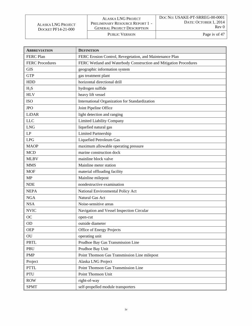
ACRONYMS AND ABBREVIATIONS
ABBREVIATION DEFINITION
Abbreviations for Units of Measurement
°F degrees Fahrenheit
BSCF/D billion standard cubic feet per day
Cfs cubic feet per second
G Gram
Hp Horsepower
Kg Kilogram
m3 cubic meters
Mg Milligram
Mm Millimeter
MMBtu/hr million British thermal units per hour
MMSCF/D million standard cubic feet per day
MTPA million metric tons per annum
ng Nanograms
Psig pounds per square inch gauge
Other Abbreviations
§ section or paragraph
The Applicants’ Plan Applicants’ Upland Erosion Control, Revegetation, and Maintenance Plan
The Applicants’ Procedures Applicants’ Wetland and Waterbody Construction and Mitigation Procedures
AD aggregate dock
ADOT&PF Alaska Department of Transportation and Public Facilities
AGDC Alaska Gasline Development Corporation
APCI Air Products and Chemicals Inc.
APDES Alaska Pollutant Discharge Elimination System
API American Petroleum Institute
ASME American Society of Mechanical Engineers
ATWS additional temporary workspace
BOG boil-off gas
C.F.R. Code of Federal Regulations
CGF central gas facility
CO2 carbon dioxide
DOT U.S. Department of Transportation
EIS Environmental Impact Statement
EPA U.S. Environmental Protection Agency
FEED front-end engineering design
FERC U.S. Federal Energy Regulatory Commission
ALASKA LNG PROJECT DOCKET PF14-21-000
ALASKA LNG PROJECT PRELIMINARY RESOURCE REPORT 1 -
GENERAL PROJECT DESCRIPTION
DOC NO: USAKE-PT-SRREG-00-0001 DATE: OCTOBER 1, 2014
Rev 0
PUBLIC VERSION Page iv of 47
iv
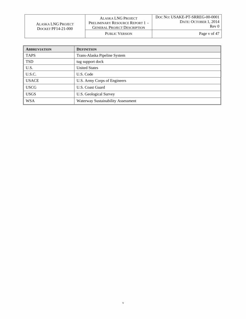
ABBREVIATION DEFINITION
FERC Plan FERC Erosion Control, Revegetation, and Maintenance Plan
FERC Procedures FERC Wetland and Waterbody Construction and Mitigation Procedures
GIS geographic information system
GTP gas treatment plant
HDD horizontal directional drill
H2S hydrogen sulfide
HLV heavy lift vessel
ISO International Organization for Standardization
JPO Joint Pipeline Office
LiDAR light detection and ranging
LLC Limited Liability Company
LNG liquefied natural gas
LP Limited Partnership
LPG Liquefied Petroleum Gas
MAOP maximum allowable operating pressure
MCD marine construction dock
MLBV mainline block valve
MMS Mainline meter station
MOF material offloading facility
MP Mainline milepost
NDE nondestructive examination
NEPA National Environmental Policy Act
NGA Natural Gas Act
NSA Noise-sensitive areas
NVIC Navigation and Vessel Inspection Circular
OC open-cut
OD outside diameter
OEP Office of Energy Projects
OU operating unit
PBTL Prudhoe Bay Gas Transmission Line
PBU Prudhoe Bay Unit
PMP Point Thomson Gas Transmission Line milepost
Project Alaska LNG Project
PTTL Point Thomson Gas Transmission Line
PTU Point Thomson Unit
ROW right-of-way
SPMT self-propelled module transporters
ALASKA LNG PROJECT DOCKET PF14-21-000
ALASKA LNG PROJECT PRELIMINARY RESOURCE REPORT 1 -
GENERAL PROJECT DESCRIPTION
DOC NO: USAKE-PT-SRREG-00-0001 DATE: OCTOBER 1, 2014
Rev 0
PUBLIC VERSION Page v of 47
v
ABBREVIATION DEFINITION
TAPS Trans-Alaska Pipeline System
TSD tug support dock
U.S. United States
U.S.C. U.S. Code
USACE U.S. Army Corps of Engineers
USCG U.S. Coast Guard
USGS U.S. Geological Survey
WSA Waterway Sustainability Assessment
ALASKA LNG PROJECT DOCKET PF14-21-000
ALASKA LNG PROJECT PRELIMINARY RESOURCE REPORT 1 -
GENERAL PROJECT DESCRIPTION
DOC NO: USAKE-PT-SRREG-00-0001 DATE: OCTOBER 1, 2014
Rev 0
PUBLIC VERSION Page vi of 47
vi
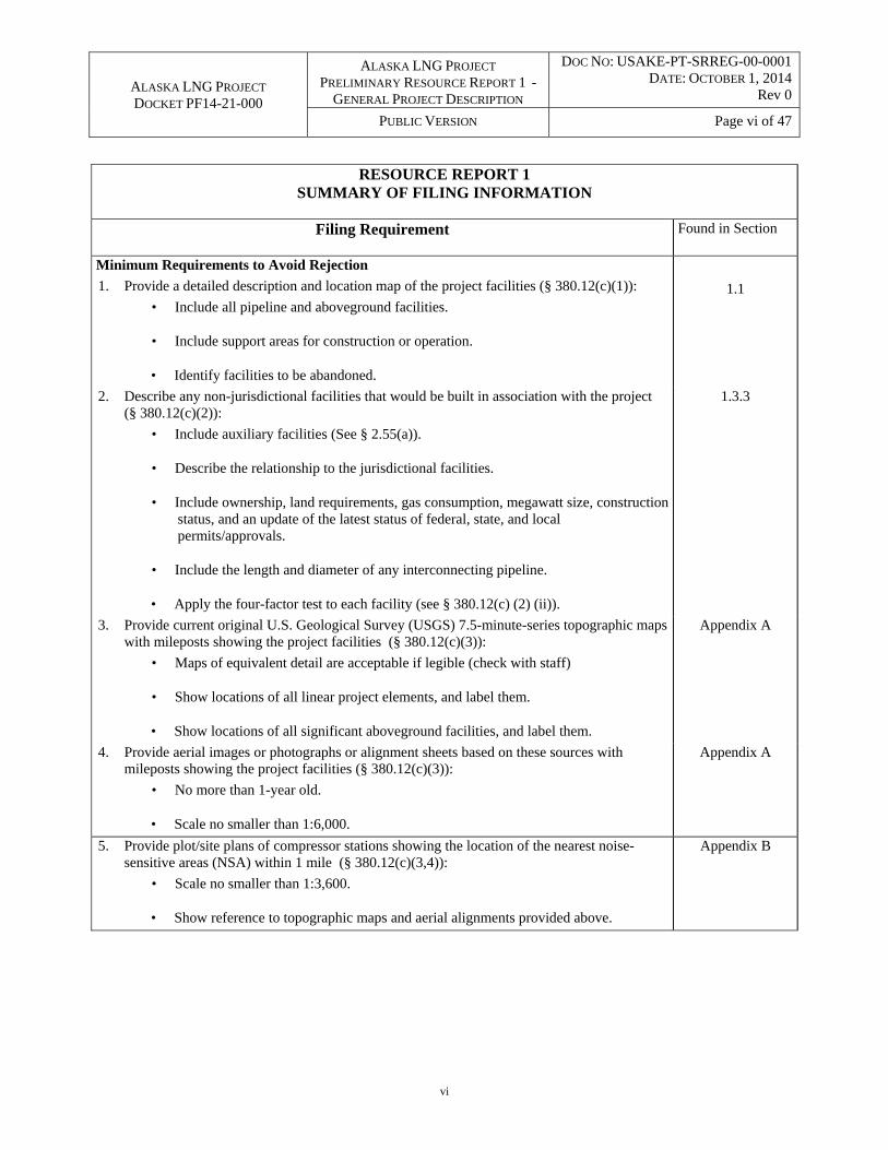
RESOURCE REPORT 1 SUMMARY OF FILING INFORMATION
Filing Requirement Found in Section
Minimum Requirements to Avoid Rejection
1. Provide a detailed description and location map of the project facilities (§ 380.12(c)(1)):
• Include all pipeline and aboveground facilities.
• Include support areas for construction or operation.
• Identify facilities to be abandoned.
1.1
2. Describe any non-jurisdictional facilities that would be built in association with the project (§ 380.12(c)(2)):
• Include auxiliary facilities (See § 2.55(a)).
• Describe the relationship to the jurisdictional facilities.
• Include ownership, land requirements, gas consumption, megawatt size, construction status, and an update of the latest status of federal, state, and local permits/approvals.
• Include the length and diameter of any interconnecting pipeline.
• Apply the four-factor test to each facility (see § 380.12(c) (2) (ii)).
1.3.3
3. Provide current original U.S. Geological Survey (USGS) 7.5-minute-series topographic maps with mileposts showing the project facilities (§ 380.12(c)(3)):
• Maps of equivalent detail are acceptable if legible (check with staff)
• Show locations of all linear project elements, and label them.
• Show locations of all significant aboveground facilities, and label them.
Appendix A
4. Provide aerial images or photographs or alignment sheets based on these sources with mileposts showing the project facilities (§ 380.12(c)(3)):
• No more than 1-year old.
• Scale no smaller than 1:6,000.
Appendix A
5. Provide plot/site plans of compressor stations showing the location of the nearest noise-sensitive areas (NSA) within 1 mile (§ 380.12(c)(3,4)):
• Scale no smaller than 1:3,600.
• Show reference to topographic maps and aerial alignments provided above.
Appendix B
ALASKA LNG PROJECT DOCKET PF14-21-000
ALASKA LNG PROJECT PRELIMINARY RESOURCE REPORT 1 -
GENERAL PROJECT DESCRIPTION
DOC NO: USAKE-PT-SRREG-00-0001 DATE: OCTOBER 1, 2014
Rev 0
PUBLIC VERSION Page vii of 47
vii
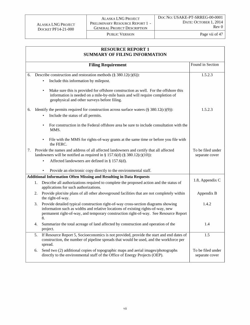
RESOURCE REPORT 1 SUMMARY OF FILING INFORMATION
Filing Requirement Found in Section
6. Describe construction and restoration methods (§ 380.12(c)(6)):
• Include this information by milepost.
• Make sure this is provided for offshore construction as well. For the offshore this information is needed on a mile-by-mile basis and will require completion of geophysical and other surveys before filing.
1.5.2.3
6. Identify the permits required for construction across surface waters (§ 380.12(c)(9)):
• Include the status of all permits.
• For construction in the Federal offshore area be sure to include consultation with the MMS.
• File with the MMS for rights-of-way grants at the same time or before you file with the FERC.
1.5.2.3
7. Provide the names and address of all affected landowners and certify that all affected landowners will be notified as required in § 157.6(d) (§ 380.12(c)(10)):
• Affected landowners are defined in § 157.6(d).
• Provide an electronic copy directly to the environmental staff.
To be filed under separate cover
Additional Information Often Missing and Resulting in Data Requests
1. Describe all authorizations required to complete the proposed action and the status of applications for such authorizations.
1.8, Appendix C
2. Provide plot/site plans of all other aboveground facilities that are not completely within the right-of-way.
Appendix B
3. Provide detailed typical construction right-of-way cross-section diagrams showing information such as widths and relative locations of existing rights-of-way, new permanent right-of-way, and temporary construction right-of-way. See Resource Report 8.
1.4.2
4. Summarize the total acreage of land affected by construction and operation of the project.
1.4
5. If Resource Report 5, Socioeconomics is not provided, provide the start and end dates of construction, the number of pipeline spreads that would be used, and the workforce per spread.
1.5
6. Send two (2) additional copies of topographic maps and aerial images/photographs directly to the environmental staff of the Office of Energy Projects (OEP).
To be filed under separate cover
ALASKA LNG PROJECT DOCKET PF14-21-000
ALASKA LNG PROJECT PRELIMINARY RESOURCE REPORT 1 -
GENERAL PROJECT DESCRIPTION
DOC NO: USAKE-PT-SRREG-00-0001 DATE: OCTOBER 1, 2014
Rev 0
PUBLIC VERSION Page 1 of 47
1
Information in this draft report, including maps, is preliminary and subject to change as plans progress. Updated information will be provided in subsequent versions of this report.
1.0 RESOURCE REPORT 1 – GENERAL PROJECT DESCRIPTION
1.1 PROJECT DESCRIPTION
The Alaska Gasline Development Corporation, BP Alaska LNG LLC, ConocoPhillips Alaska LNG Company, ExxonMobil Alaska LNG LLC, and TransCanada Alaska Midstream LP (Applicants) plan to construct one integrated LNG Project (Project) with interdependent facilities for the purpose of liquefying supplies of natural gas from Alaska, in particular the Point Thomson Unit and Prudhoe Bay Unit production fields on the Alaska North Slope (North Slope), for export in foreign commerce.
The Natural Gas Act (NGA) (15 U.S.C. § 717a(11) (2006)) and FERC regulations (18 C.F.R. § 153.2(d) (2014)) define “LNG terminal” to include “all natural gas facilities located onshore or in State waters that are used to receive, unload, load, store, transport, gasify, liquefy, or process natural gas that is ... exported to a foreign country from the United States.” With respect to this Project, the “LNG terminal” includes: a liquefaction facility (Liquefaction Facility) in south central Alaska; an approximately 800-mile, large diameter gas pipeline (Mainline); a gas treatment plant (GTP) on the North Slope; a gas transmission line connecting the GTP to the Point Thomson Unit (PTU) gas production facility (PTU Gas Transmission Line or PTTL); and a gas transmission line connecting the GTP to the Prudhoe Bay Unit (PBU) gas production facility (PBU Gas Transmission Line or PBTL). All of these facilities are essential to export natural gas in foreign commerce.
These components are shown in Figure 1.1-1 and their current basis for design is described below.
The new Liquefaction Facility will be constructed on the eastern shore of Cook Inlet in the Nikiski area of the Kenai Peninsula. The Liquefaction Facility will include the structures, equipment, underlying access rights and all other associated systems for pre-processing (other than that performed by the GTP) and liquefaction of natural gas, and storage and loading of LNG, including terminal facilities (dock) and auxiliary marine vessels used in support of marine terminal operations (excluding LNG carriers). The Liquefaction Facility includes three liquefaction trains combining to process up to approximately 20 million metric tons per annum (MTPA) of LNG. Three 160,000 cubic meter (m3) tanks will be constructed to store the LNG. The Liquefaction Facility will be capable of accommodating two LNG carriers. The size range of LNG carriers that the Liquefaction Facility will accommodate is to be determined through further engineering study and consultation with the United States Coast Guard (USCG) as part of the Waterway Suitability Assessment (WSA) process.
In addition to the Liquefaction Facility, the LNG Terminal includes the following interdependent facilities:
Mainline: A new large-diameter natural gas pipeline approximately 800 miles in length extending from the Liquefaction Facility to the GTP on the North Slope, including the structures, equipment, and all other associated systems. The Mainline will include: compressor stations, heater stations, meter stations, and various mainline block valves within the permanent pipeline right-of-way footprint; pig launcher and receiver facilities; and associated ancillary and auxiliary facilities. Ancillary and auxiliary facilities will include additional temporary work spaces, access

!
!
!
!
!
!
!
!
!
!!
!
!!
!
!
!!
!
!!!
!
!
!
!
!
!
!
!
! ! !
!
")
GTPFACILITY PT THOMSON
") LIQUEFACTIONFACILITY
")
KENAINIKISKI
ANDERSON
TYONEKBELUGA ANCHORAGE
WILLOW
TRAPPER CREEK TALKEETNA
MINTO
RAMPART
ALLAKAKETALATNA
STEVENS VILLAGE
EVANSVILLEBETTLES
COLDFOOTWISEMAN
WASILLA
VALDEZ
CANTWELL
HEALY
McKINLEYVILLAGE TOK
NENANAFAIRBANKS
LIVENGOOD
DELTAJUNCTION
ANAKTUVUKPASS
BIG LAKE
NUIQSUTPRUDHOEBAY KAKTOVIK
Porcupine
Susitina
Kuskokwim
Colville
Koyuk
uk
Yukon
N o r t hN o r t hS l o p eS l o p e
B o r o u g hB o r o u g h
N o r t h w e s tN o r t h w e s tA r c t i cA r c t i c
B o r o u g hB o r o u g h
F a i r b a n k s N o r t hF a i r b a n k s N o r t hS t a rS t a r
B o r o u g hB o r o u g h
M a t a n u s k a - S u s i t n aM a t a n u s k a - S u s i t n aB o r o u g hB o r o u g h
B e t h e lB e t h e lC e n s u sC e n s u s
A r e aA r e aK e n a iK e n a i
P e n i n s u l aP e n i n s u l aB o r o u g hB o r o u g hD i l l i n g h a mD i l l i n g h a m
C e n s u sC e n s u sA r e aA r e a
L a k e a n dL a k e a n dP e n i n s u l aP e n i n s u l a
B o r o u g hB o r o u g h
V a l d e z - C o r d o v aV a l d e z - C o r d o v aC e n s u s A r e aC e n s u s A r e a
Y u k o n - K o y u k u kY u k o n - K o y u k u kC e n s u s A r e aC e n s u s A r e a
S o u t h e a s tS o u t h e a s tF a i r b a n k sF a i r b a n k s
C e n s u s A r e aC e n s u s A r e aD e n a l iD e n a l iB o r o u g hB o r o u g h
NelchinaPublic
Use Area
Wrangell-St.Elias National
Park
Wrangell-St.Elias National
Preserve
Lake ClarkNational Park
NoatakNationalPreserve
Kobuk ValleyNational
Park
DenaliNational
Park
Gates ofthe Arctic
National Park
Arctic NationalWildlife Refuge
Nowitna NationalWildlife Refuge
YukonFlats National
Wildlife Refuge
!
!
!
! CanadaAlaska
ANCHORAGE
FAIRBANKSLIVENGOOD
PRUDHOEBAY LEGENDVICINITY MAP
0 50 10025 Miles
FIGURE 1.1-1PROJECT OVERVIEW
MAP
!°
SCALE:1 of 1
EXP ENERGY SERVICES INC.PREPARED BY:1:5,000,000
2014-09-15 SHEET:DATE:
! Alaska Place NamesPre-FEED Rev A Base CorridorPre-FEED Rev A Alternate CorridorBorough/Census Area Boundary
Major HighwaysMajor RiversFederal LandsState Lands
DATA SOURCES(1) Alaska Project Data(2) AKDOT(3) AKDNR(4) USGS
X:\Projects\ExxonMobil\SCLNG\Mapping\20140910_Resource_Report_Rev_C\04_MXD\01_Ver0\Prj_Overview_map_Pre_FEED.mxd
CANADAALASKA

ALASKA LNG PROJECT DOCKET PF14-21-000
ALASKA LNG PROJECT PRELIMINARY RESOURCE REPORT 1 -
GENERAL PROJECT DESCRIPTION
DOC NO: USAKE-PT-SRREG-00-0001 DATE: OCTOBER 1, 2014
Rev 0
PUBLIC VERSION Page 3 of 47
3
roads, helipads, construction camps, pipe storage areas, contractor yards, material extraction sites, and material disposal sites. Along the Mainline route, there will be at least five off-take interconnection points to allow for the opportunity for future in-state deliveries. The size and location of such interconnection points are unknown at this time. None of the facilities used to move natural gas away from these off-take points will be part of the Project.
GTP: The Project includes a new GTP and associated facilities near the PBU for receiving natural gas from the PBU Gas Transmission Line, the PTU Gas Transmission Line and/or other facilities. The GTP will treat/process the natural gas to provide an average annual capacity of up to 3.4 billion standard cubic feet per day (BSCF/D) of treated gas to the Mainline (3.7 BSCF/D peak flow). The Project also includes a new pipeline that will deliver gas processing byproducts from the GTP to the PBU.
PBU Gas Transmission Line: The Project includes a new natural gas transmission line extending approximately one mile from the inlet flange of the GTP to the outlet flange of the PBU gas production facility.
PTU Gas Transmission Line: The Project includes a new natural gas transmission line extending approximately 60 miles from the inlet flange of the GTP to the outlet flange of the PTU gas production facility.
Ancillary Facilities: Existing State of Alaska transportation infrastructure will be used during the construction of these new facilities. Existing airports, roads, airstrips (potentially including previously abandoned airstrips) will also be used. The potential need for new infrastructure and modifications or additions to these existing in-state facilities is under evaluation. The GTP and Liquefaction Facility sites will require the construction of material offloading facilities.
Appendices A and B contain general maps of the Project footprint. Detailed plot plans will be developed during the pre-front-end engineering and design (pre-FEED) process and will be provided to the Commission. Additional work related to the proposed Project, but outside the scope of the Project, will likely need to be completed by other entities and/or the State of Alaska. These other projects may include:
Expansion of the PTU (PTU operator);
Modifications/new facilities at the PBU (PBU operator);
Relocation of the Kenai Spur Highway (Alaska Department of Transportation & Public Facilities [ADOT&PF]); and
Third party pipeline and associated infrastructure to transport natural gas from the off-take interconnection points to markets in Alaska.

ALASKA LNG PROJECT DOCKET PF14-21-000
ALASKA LNG PROJECT PRELIMINARY RESOURCE REPORT 1 -
GENERAL PROJECT DESCRIPTION
DOC NO: USAKE-PT-SRREG-00-0001 DATE: OCTOBER 1, 2014
Rev 0
PUBLIC VERSION Page 4 of 47
4
1.2 PROJECT PURPOSE AND NEED
The purpose of the Alaska LNG Project is to enable the commercialization of the vast natural gas resources1 that were initially discovered on Alaska’s North Slope in 1968. These resources have remained stranded for decades despite numerous previous attempts to promote the development of infrastructure to bring natural gas to market and to capitalize on Alaska’s abundant natural gas resource base. Now, for the first time, the Applicants, supported by the State of Alaska, have aligned to progress the development of the Project and have determined that the most economical and beneficial solution to commercializing North Slope natural gas is to transport the gas from the North Slope via pipeline to a new Liquefaction Facility in south central Alaska for export to foreign markets.
It has been estimated that there will be significant demand for LNG exports from Alaska, and that natural gas will also be required for in-state consumption over the same period.2 This Project will facilitate LNG export to foreign markets, and, in addition, will include at least five off-take points to allow for the opportunity for future in-state deliveries of natural gas.
The Project will be the largest integrated natural gas/LNG project of its kind designed and constructed in the United States, with an estimated cost of $45 billion to $65 billion. It will result in the following benefits, all of which are consistent with the public interest:
Stimulate the Alaska state, regional and national economies through job creation, an enhanced tax base, and an increase in overall economic activity, thus producing “unequivocally positive” economic impacts in Alaska and the United States as a whole;3
Create up to 15,000 jobs during construction and approximately 1,000 jobs for operation of the Project;
Develop infrastructure for future exploration and production opportunities; and
Provide the opportunity for a reliable in-state gas supply that potentially will enable future economic development.
1.3 LOCATION AND DESCRIPTION OF FACILITIES
An overview of the Project’s planned facilities and locations is provided as Figure 1.1-1. The current design study corridor and preliminary locations of major facilities are depicted on aerial imagery and U.S. Geological Survey (USGS) maps provided in Appendix A. Preliminary plot plans and/or facility maps are provided in Appendix B.
Across the Project footprint, work is underway to define the facility locations. An approximately 2,000-feet wide study corridor for the Mainline and PTTL has been identified and is presented in the
1 See, e.g., DeGolyer and MacNaughton, “Report on a Study of Alaska Gas Reserves and Resources for Certain Gas Supply Scenarios as of December 31, 2012” at Figure 5 (April 2014).
2 NERA Economic Consulting, “Socio-Economic Impact Analysis of Alaska LNG Project” at Figure 3 (June 19, 2014) (“Socio-Economic Report”).
3 Id. at 4-5.
ALASKA LNG PROJECT DOCKET PF14-21-000
ALASKA LNG PROJECT PRELIMINARY RESOURCE REPORT 1 -
GENERAL PROJECT DESCRIPTION
DOC NO: USAKE-PT-SRREG-00-0001 DATE: OCTOBER 1, 2014
Rev 0
PUBLIC VERSION Page 5 of 47
5
appendices. Within this study corridor, a preliminary route is being identified during pre-FEED and refined during future Project phases based on data collected in subsequent summer field seasons. North of the community of Livengood, Alaska, the Project design incorporates certain prior work related to commercializing North Slope natural gas. The routing for the PBTL is under investigation and will be provided to the Commission.
1.3.1 Liquefaction Facility
The Liquefaction Facility will be a new facility constructed on the eastern shore of Cook Inlet in the Nikiski area of the Kenai Peninsula, within the area depicted in the appendices. Factors contributing to the site selection of the Liquefaction Facility include, but are not limited to, access to deep water shipping channels close to shore; relatively level ground to facilitate construction; proximity to existing industrial facilities; and pre-existing oil and gas businesses and infrastructure in Nikiski and Kenai.
The LNG Plant includes storage and liquefaction processing facilities and the Marine Terminal includes the trestle(s), piping, and berthing facilities associated with LNG carrier loading and berthing. Together, the LNG Plant and Marine Terminal comprise the Liquefaction Facility.
1.3.1.1 LNG Plant
Gas treated by the GTP and delivered to Nikiski via the Mainline will flow from the LNG Plant receipt point (plant inlet flange) through a pressure letdown station and undergo flow control, separation and filtration. Molecular sieve dehydration beds will remove water vapor, and mercury guard beds will reduce the mercury to levels that meet the liquefaction system equipment specifications. The gas will be liquefied through a combination of heat exchange and pressure reduction using Air Products and Chemicals Inc. (APCI) patented technology. LNG is then pumped to the LNG storage tanks for subsequent delivery to LNG carriers. The current design basis includes three 160,000-m3 LNG storage tanks. Pre-FEED studies will finalize the design of the LNG Plant including the size and number of LNG storage tanks.
1.3.1.2 Marine Terminal
The Marine Terminal will be constructed in the Cook Inlet and allow LNG carriers to dock and load LNG. Marine facilities will be designed for two loading berths and will include:
LNG trestles to support two loading berths to accommodate LNG carriers;
Cryogenic pipelines from the LNG tanks to the loading berths and vapor return lines;
Tug and support vessel dock; and
Material Offloading Facility (MOF).
1.3.1.3 Other Infrastructure
To operate the Liquefaction Facility, additional facilities will be built and maintained on site. The current design basis that will be studied and optimized during pre-FEED may include:
ALASKA LNG PROJECT DOCKET PF14-21-000
ALASKA LNG PROJECT PRELIMINARY RESOURCE REPORT 1 -
GENERAL PROJECT DESCRIPTION
DOC NO: USAKE-PT-SRREG-00-0001 DATE: OCTOBER 1, 2014
Rev 0
PUBLIC VERSION Page 6 of 47
6
Plant flares;
Marine flare;
Refrigerant storage;
Miscellaneous storage (lube oil, chemical, low sulfur diesel, etc.);
Condensate storage;
Liquefied petroleum gas (LPG) storage;
Fuel gas system;
Defrost gas system;
LNG storage and loading system;
Boil-off gas (BOG) compression;
Effluent and wastewater treatment;
Water systems;
Demineralized water;
Seawater intake system;
Power generation and power distribution;
Cooling system;
Steam system;
Firewater systems;
Plant/instrument air;
Heating medium system;
Waste heat recovery;
Nitrogen system;
Diesel fueling system;
Liquefaction facility operations control building; and

ALASKA LNG PROJECT DOCKET PF14-21-000
ALASKA LNG PROJECT PRELIMINARY RESOURCE REPORT 1 -
GENERAL PROJECT DESCRIPTION
DOC NO: USAKE-PT-SRREG-00-0001 DATE: OCTOBER 1, 2014
Rev 0
PUBLIC VERSION Page 7 of 47
7
Loading operations control building.
1.3.1.4 Other Facilities Associated with the Construction of the Liquefaction Facility
In addition to the permanent facilities identified above, the Liquefaction Facility will require the following facilities during construction:
A construction camp and other infrastructure to support the large workforce;
Temporary infrastructure to support construction (e.g., concrete batch plant(s), construction equipment storage, contractor and owner offices, and laydown areas);
Gravel and sand from nearby sources;
Disposal areas for blast rock and other construction debris;
Water to mix concrete and for hydrostatically testing the tanks;
MOF to facilitate handling of pre-fabricated modules transported from vessels and marine heavy lift vessels (HLVs);
A separate Aggregate Dock (AD) to handle off-loading of bulk materials needed for the Liquefaction Facility; and
A Marine Construction Dock (MCD) to accommodate the needs during construction of the Marine Terminal portion of the Liquefaction Facility.
1.3.2 Other Project Facilities
In addition to the Liquefaction Facility, Project facilities include the Mainline, GTP, PBU Gas Transmission Line, and PTU Gas Transmission Line as presented in Table 1.3.2-1 to move and process natural gas from the North Slope to the Liquefaction Facility. Appendix A map books have placed mileposts on the pipelines according to convention to reflect gas flow (i.e., from north to south in the case of the Mainline and from east to west in the case of the PTTL).
TABLE 1.3.2-1
Associated Facilities
Segment or Facility Name Boroughs or Census Areas Approximate Length (miles)*
Mainline ~805 (819)
Kenai Peninsula Borough ~21.5 (43.9)
Cook Inlet Crossing ~28.2 (27.4)
Matanuska-Susitna Borough ~178 (170.6)
Denali Borough ~88.1 (88.1)
Fairbanks North Star Borough ~2.5 (2.5)
ALASKA LNG PROJECT DOCKET PF14-21-000
ALASKA LNG PROJECT PRELIMINARY RESOURCE REPORT 1 -
GENERAL PROJECT DESCRIPTION
DOC NO: USAKE-PT-SRREG-00-0001 DATE: OCTOBER 1, 2014
Rev 0
PUBLIC VERSION Page 8 of 47
8
Yukon-Koyukuk Census Area ~311.4 (311.4)
North Slope Borough ~174.9 (174.9)
GTP North Slope Borough N/A
PTTL North Slope Borough ~60
PBTL North Slope Borough ~1
*The two mileage numbers presented reflect the preferred corridor first and then the alternate corridor. 1.3.2.1 Mainline
The Mainline will be a new large-diameter natural gas pipeline, approximately 800 miles in length, extending from the Liquefaction Facility to the GTP on the North Slope. As presented in Table 1.3.2-1, the Mainline will originate in the Kenai Peninsula Borough, traverse the Matanuska-Susitna Borough, the Denali Borough, and the Yukon-Koyukuk Census Area, and terminate in the North Slope Borough at the new GTP. The Mainline’s current design platform is a 42-inch-diameter pipeline, with a maximum allowable operating pressure (MAOP) of 2,075 pounds per square inch gauge (psig), and an initial annual average receipt capacity of 3.4 BSCF/D. This design platform will be further validated through the Pre-FEED studies.
The Mainline corridor crosses Kenai Peninsula in a northerly direction to Boulder Point. From there it heads north crossing Cook Inlet to the vicinity of Shorty Creek on the northern shore of Cook Inlet. The corridor next heads in a north-northwesterly direction across the Beluga highway, around Viapan Lake. It then turns in a north-northeasterly direction across the Beluga highway to continue northerly on the west side of the Susitna River to the Deshka River crossing. From there, the pipeline corridor follows the Parks Highway (Alaska Highway 3) north-northeast to a point just north of the town of Trapper Creek. At that point, the Mainline corridor heads north-northeast to the vicinity of Livengood. From Livengood, the Mainline corridor follows the Dalton Highway and Trans-Alaska Pipeline System (TAPS) corridor north to the GTP. The corridor will cross the Beluga, Theodor, Lewis, Ivan, Yentna, Deshka, Tanana, and Yukon Rivers among others.
An alternative corridor from the Nikiski site to just north of the Deshka River is currently under investigation by the engineering team. This alternative follows the northern coast of the Kenai Peninsula and crosses Cook Inlet between Boulder Point and Moose Point, coming ashore west of Point MacKenzie. From there the alternative corridor crosses the Little Susitna and Big Susitna Rivers and continues north (see Figure 1.1-1). This corridor (depicted on maps provided in Appendix A) follows a more northeasterly direction to a point just north of the Deshka River.
North of the Brooks Range, the natural gas in the pipeline will be cooled to below freezing to maintain the stability of thaw-sensitive soils, thereby reducing thaw-related movement of the pipeline. South of the Brooks Range, seasonal variation in station discharge gas temperature will range from below freezing in the winter to above freezing in the summer.
1.3.2.2 Mainline Aboveground Facilities
The Mainline includes several aboveground pipeline facilities. The current design includes eight compressor stations; four custody transfer meter stations, as specified below; and multiple pig launching/receiving stations, heater stations, and mainline block valves (MLBV). This design platform will be further validated through the Pre-FEED studies.

ALASKA LNG PROJECT DOCKET PF14-21-000
ALASKA LNG PROJECT PRELIMINARY RESOURCE REPORT 1 -
GENERAL PROJECT DESCRIPTION
DOC NO: USAKE-PT-SRREG-00-0001 DATE: OCTOBER 1, 2014
Rev 0
PUBLIC VERSION Page 9 of 47
9
Compressor Stations
Compressor stations will be placed along the Mainline at intervals where gas pressure will need to increase to offset pressure losses caused by friction. The current design includes a turbo-compressor package consisting of one or more natural gas-fueled turbines (nominally International Organization for Standardization (ISO)-rated at 30,000 horsepower) driving a centrifugal compressor. The gas turbine may include the following associated equipment:
Self-cleaning intake air filter and silencer;
Electric variable frequency drive starter motor;
Gas-turbine exhaust gas duct and silencing equipment;
Lube oil systems and skids complete with lube oil cooling equipment; and
Skid-mounted integral control panels.
The following auxiliary facilities may be included at a compressor station:
Station and unit control systems designed for remote monitoring and operation from a gas control center;
Gas engine driven power generators, configured in a “two operating, plus one standby” arrangement;
Fuel gas system to provide fuel gas for the gas turbine;
Utility and power gas systems to provide utility and power gas to auxiliary equipment;
Glycol/hot water system to heat buildings, fuel, and utility gas;
Instrument air and utility air systems to supply clean, dry, compressed air to control valves, pneumatic instrumentation, and maintenance stations;
Living quarters to provide intermittent accommodation for four to six personnel; and
Helicopter landing pad.
Communication facilities will be included at the compressor site. Pre-FEED engineering studies will determine the types of communication systems to be used.
Intermediate natural gas compression is not expected to be required on the PBTL or the PTTL.
ALASKA LNG PROJECT DOCKET PF14-21-000
ALASKA LNG PROJECT PRELIMINARY RESOURCE REPORT 1 -
GENERAL PROJECT DESCRIPTION
DOC NO: USAKE-PT-SRREG-00-0001 DATE: OCTOBER 1, 2014
Rev 0
PUBLIC VERSION Page 10 of 47
10
Heater Station
The current design requires heater stations to maintain gas temperature above a minimum value in colder seasons. Pipeline gas enters the station and flows through a number of identical trains configured in a parallel arrangement.
Custody Transfer Meter Stations
The current design includes four meter stations associated with the receipt of gas at the Liquefaction Facility and the GTP:
Liquefaction Meter Station: located at the Liquefaction Facility to provide custody transfer measurement of sales-quality gas entering the Liquefaction Facility at Nikiski;
Mainline Meter Station: located at the GTP to provide custody transfer measurement of sales-quality gas entering the Mainline from the GTP;
Prudhoe Bay Meter Station: located at the GTP to provide custody transfer measurement of gas delivered to the GTP through the PBTL from the Central Gas Facility (CGF); and
Point Thomson Meter Station: located at the PTU to provide custody transfer measurement of gas deliveries from the PTU to the GTP through the PTTL.
Other than pipe size, the meter stations will have consistent designs.
Mainline Block Valves (MLBVs)
MLBVs are used to segment the pipeline for safety, operations, and maintenance purposes. MLBVs will be sited at locations to meet regulatory, operational, and engineering requirements. For the Mainline, one MLBV will be located at each compressor station, heater station, and meter station, and the remaining MLBVs will be standalone facilities along the Mainline. In addition to the block valve and operator, each MLBV site will typically include blow-down valves and a line break control system to close the valve upon detection of a low-pressure condition. A helipad will be located adjacent to standalone MLBV sites.
For the PTTL, MLBVs will be located with the facilities at start and end of the pipeline, and the remaining MLBVs will be standalone facilities along the PTTL. The PBTL is still under evaluation.
Launchers/Receivers
The Mainline, PBTL, and PTTL will be designed to allow passage of in-line inspection tools and cleaning pigs throughout their entire lengths. Launchers and receivers are planned for locations along the pipelines to facilitate cleaning and integrity management operations.
Off-Take Interconnection Points
Installation of a tee with an isolation valve will occur at several points along the Mainline to allow for the opportunity for future in-state deliveries. The timing of construction, size, and location of the meter stations at these interconnection points are not known at this time.
ALASKA LNG PROJECT DOCKET PF14-21-000
ALASKA LNG PROJECT PRELIMINARY RESOURCE REPORT 1 -
GENERAL PROJECT DESCRIPTION
DOC NO: USAKE-PT-SRREG-00-0001 DATE: OCTOBER 1, 2014
Rev 0
PUBLIC VERSION Page 11 of 47
11
Cathodic Protection Facilities
A cathodic protection system for the pipeline facilities will be installed and maintained in accordance with applicable codes and regulations. The cathodic protection system test stations, positioned on aboveground posts, will be located at approximately two-mile intervals along both the Mainline and the PTTL. All cathodic protection system facilities (i.e., ground beds and rectifiers) associated with the Mainline and PTTL will be located at selected compressor stations, meter stations, and MLBV sites to the extent practical. The PBTL is still under evaluation.
Aboveground Pipeline Construction
For selected sections of the respective routes, the Mainline, PTTL, and PBTL will be installed above ground using a combination of vertical support members, horizontal support members and/or sleepers. Aboveground installation of pipeline may be required at certain fault crossings, areas of permafrost conditions and/or terrain conditions, and river and stream crossings. Pre-FEED engineering studies will determine where the Mainline is required to be installed above ground and the design necessary to address the constraints at each selected location.
1.3.2.3 Pipeline Construction Infrastructure
Construction of the pipelines will require the use of additional temporary facilities and other resources in the area of the permanent pipeline right-of-way (ROW). The associated infrastructure may include:
Temporary workspace for construction activities (e.g., staging areas, truck turnarounds, utility crossovers, etc.);
Access roads and shooflies to transport equipment, material, pipe, and personnel to the Project area, some of which may be maintained for permanent use during operations;
Water sourcing facilities to support snow and ice road construction and hydrostatic testing activities;
Equipment fueling facilities;
Helipads to transport personnel to remote locations;
Airstrips for transporting personnel and freight to and from the Project area;
Construction camps to house workers in remote areas;
Pipe storage areas for stockpiling pipe prior to installation;
Existing and new material sites to supply sand and gravel for construction of the pipelines and related facilities;
Disposal sites for excavated material, stumps, and slash removed from the permanent pipeline ROW;
ALASKA LNG PROJECT DOCKET PF14-21-000
ALASKA LNG PROJECT PRELIMINARY RESOURCE REPORT 1 -
GENERAL PROJECT DESCRIPTION
DOC NO: USAKE-PT-SRREG-00-0001 DATE: OCTOBER 1, 2014
Rev 0
PUBLIC VERSION Page 12 of 47
12
Pipe coating yard and concrete coating facility; and
Contractor yards for construction staging, material storage, and other contractor needs.
Potential infrastructure locations associated with construction support have been identified north of Livengood and will be reexamined during pre-FEED, whereas potential locations south of Livengood are under development. A list of proposed locations will be provided to the Commission.
1.3.2.4 Gas Treatment Plant (GTP)
The GTP is designed to treat natural gas received from the PBU and the PTU for delivery to the Mainline. The GTP will be constructed on the North Slope near the Beaufort Sea coast (see Figure 1.1-1). The GTP facility will be located entirely within the existing PBU, which is located on State land within the North Slope Borough. The GTP will have an initial gas treating capacity up to 4.3 BSCF/D of feed gas and will be able to accommodate varying compositions of gas relating to supply received from the PBU and PTU. Current design for the GTP consists of three parallel treatment trains, each of which removes CO2, H2S, and some of the water from the feed gas. The gas then will be compressed in stages and routed to a gas chilling unit. The chilling unit utilizes a refrigerant to cool the gas. Cooling the gas will help to maintain the stability of the thaw-sensitive soils within the section of the Mainline north of the Brooks Range. After refrigeration, the gas will be delivered to the Mainline at pressures up to 2,075 psig.
The GTP will include facilities to collect the CO2 and H2S byproduct streams from each of the treatment units. These streams also will contain water and some hydrocarbons. The byproduct streams from each train will be compressed and treated to remove water before transportation to the PBU for re-injection. The byproduct streams then will be transported to the PBU for injection via an approximately one mile pipeline, the diameter of which is under evaluation. The byproduct pipeline is being designed to transport an annual average of 490 million standard cubic feet per day (MMSCF/D) of CO2 and H2S (peak flow of 520 MMSCF/D). The byproduct pipeline will be elevated and cross land managed by the State of Alaska.
1.3.2.5 Associated GTP Infrastructure
Development of the GTP requires the construction of infrastructure, including:
Improvements to the existing PBU West Dock loading/unloading facilities, additional dredging to facilitate delivery of modules by vessel, and widening of the access road from the West Dock;
Module staging area near the existing West Dock;
Temporary ice roads for winter construction and permanent gravel roads for access from the West Dock area to the GTP;
Construction camp on the GTP site footprint to house workers;
Temporary infrastructure to support construction (e.g., concrete batch plant(s), construction equipment storage, contractor and owner offices, and laydown areas);
ALASKA LNG PROJECT DOCKET PF14-21-000
ALASKA LNG PROJECT PRELIMINARY RESOURCE REPORT 1 -
GENERAL PROJECT DESCRIPTION
DOC NO: USAKE-PT-SRREG-00-0001 DATE: OCTOBER 1, 2014
Rev 0
PUBLIC VERSION Page 13 of 47
13
Use of existing material sites to supply sand and gravel for construction of the GTP and related facilities; and
Water reservoir, pump facilities, and a transfer line to provide water for GTP construction and operation.
1.3.2.6 PBU Gas Transmission Line (PBTL)
According to the current design, the PBTL will be an approximately one-mile, large diameter aboveground pipeline to transport gas from the CGF to the GTP, with an annual average capacity up to 4.1 BSCF/D (peak capacity of 4.4 BSCF/D). The PBTL will be installed on vertical support members and coated with fusion bond epoxy over its full length, insulated, and jacketed. The PBTL will cross public lands managed by the State of Alaska.
1.3.2.7 PTU Gas Transmission Line (PTTL)
According to the current design, the PTTL will be an approximately 60-mile pipeline, with a maximum 30-inch diameter, to transport gas from the PTU to the GTP. The current design calls for an annual average receipt capacity of 950 MMSCF/D with a MAOP of 1,130 psig (peak capacity of 1 BSCF/D). The PTTL will be located entirely within the North Slope Borough. The PTTL will head east from the GTP, crossing the Putuligayuk, Sagavanirktok, Kadleroshilik, and Shaviovik Rivers before following east along the south side of the existing Badami pipeline, all the way to the PTU. The route is intended to avoid multiple crossings of existing oil pipelines.
Pre-FEED studies will determine the best installation method (i.e., buried or elevated) for the PTTL. No active faults are crossed by the current PTTL route. If the PTTL is buried, the natural gas from the PTU will be cooled to temperatures below freezing prior to delivery to the PTTL to maintain the stability of thaw-sensitive soils. The PTTL will cross public lands managed by the State of Alaska.
1.3.3 Non-Jurisdictional Facilities
There is a possibility that additional facilities or expansion/modification of existing facilities in support of the Project would be built by third parties. These facilities would be beyond FERC’s jurisdiction.
In determining whether to include these non-jurisdictional facilities in the FERC Resource Reports, and ultimately the Environmental Impact Statement (EIS), the Applicants and FERC determine whether they are connected actions. Applying FERC’s four-factor test,4 these additional facilities will not be built or modified “but for” the Project. These facilities, although not regulated by FERC, are presented here in the environmental documents for consideration along with the proposed action in the EIS.
4 These factors are: • Whether or not the regulated activity comprises “merely a link” in a corridor type project (e.g., a transportation or utility
transmission project). • Whether there are aspects of the non-jurisdictional facility in the immediate vicinity of the regulated activity which uniquely
determine the location and configuration of the regulated activity. • The extent to which the entire project will be within the Commission’s jurisdiction. • The extent of cumulative federal control and responsibility. Refer to the Commission’s June 2, 1992 order in Docket No. CP91-1983
ALASKA LNG PROJECT DOCKET PF14-21-000
ALASKA LNG PROJECT PRELIMINARY RESOURCE REPORT 1 -
GENERAL PROJECT DESCRIPTION
DOC NO: USAKE-PT-SRREG-00-0001 DATE: OCTOBER 1, 2014
Rev 0
PUBLIC VERSION Page 14 of 47
14
The potential non-jurisdictional facilities identified below will be discussed as necessary in subsequent drafts of this and other Resource Reports once additional information is available from responsible third parties.
1.3.3.1 Point Thomson Unit Expansion
The PTU expansion may include:
Installation of up to 13 additional wells;
A new gravel well pad and connecting road;
Expansion of the existing central pad;
Expansion of condensate production facilities;
Addition of gas conditioning facilities;
Expansion of gathering system; and
New on-site access roads; and
Modifications to existing marine infrastructure (e.g., adding dolphins as needed to offload barges).
The expansion would be designed, permitted, constructed, and operated by the PTU operator. The timing of this construction would coincide with the construction of the PTTL.
1.3.3.2 Prudhoe Bay Unit Modifications
Modifications at the PBU may include:
New tie-ins at the PBU CGF and a new metering module for gas delivery to the PBTL;
A new CO2 receiving module, CO2 injection module and possibly injection wells for CO2 receipt and injection, and
A new pipeline from the CO2 receipt module to existing gas cap injection wells for a back-up CO2 injection location.
These modifications would be completed by the PBU operator in the same timeframe as GTP construction.
1.3.3.3 Kenai Spur Highway Relocation
The planned Liquefaction Facility location would require that the existing Kenai Spur Highway be relocated to allow for site safety and security buffer zones. ADOT&PF would be responsible for
ALASKA LNG PROJECT DOCKET PF14-21-000
ALASKA LNG PROJECT PRELIMINARY RESOURCE REPORT 1 -
GENERAL PROJECT DESCRIPTION
DOC NO: USAKE-PT-SRREG-00-0001 DATE: OCTOBER 1, 2014
Rev 0
PUBLIC VERSION Page 15 of 47
15
designing, permitting, constructing, and operating the relocation. The road relocation would need to be designed, permitted, and constructed prior to the start-up of the Liquefaction Facility.
1.3.3.4 Third Party Pipelines
Other parties may build pipelines and other facilities to move gas from the Mainline to local communities and/or pipeline distribution systems within the State of Alaska. These pipelines are not part of the scope of the Project.
1.4 LAND REQUIREMENTS
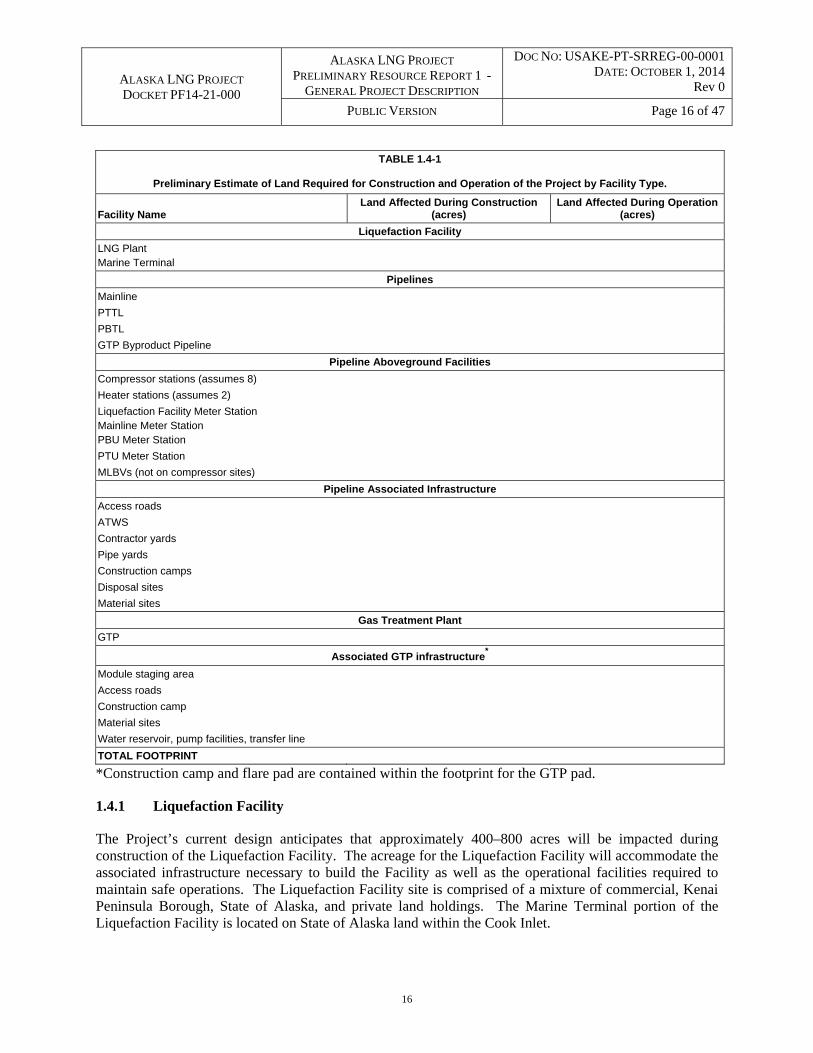
The Project’s current design includes approximately 30,000 acres of land that will be temporarily affected by construction of the Project. Following completion of construction, approximately 15,000 of these acres will be permanently converted for operation of the Project facilities. More specific acreages relating to the Project components will be provided in future drafts of this resource report. Table 1.4-1 shows how the acreage affected during construction and operation of all Project facilities will be presented in such future drafts. .
ALASKA LNG PROJECT DOCKET PF14-21-000
ALASKA LNG PROJECT PRELIMINARY RESOURCE REPORT 1 -
GENERAL PROJECT DESCRIPTION
DOC NO: USAKE-PT-SRREG-00-0001 DATE: OCTOBER 1, 2014
Rev 0
PUBLIC VERSION Page 16 of 47
16
TABLE 1.4-1
Preliminary Estimate of Land Required for Construction and Operation of the Project by Facility Type.
Facility Name Land Affected During Construction
(acres) Land Affected During Operation
(acres)
Liquefaction Facility
LNG Plant
Marine Terminal
Pipelines
Mainline
PTTL
PBTL
GTP Byproduct Pipeline
Pipeline Aboveground Facilities
Compressor stations (assumes 8)
Heater stations (assumes 2)
Liquefaction Facility Meter Station Mainline Meter Station PBU Meter Station
PTU Meter Station
MLBVs (not on compressor sites)
Pipeline Associated Infrastructure
Access roads
ATWS
Contractor yards
Pipe yards
Construction camps
Disposal sites
Material sites
Gas Treatment Plant
GTP
Associated GTP infrastructure*
Module staging area
Access roads
Construction camp
Material sites
Water reservoir, pump facilities, transfer line
TOTAL FOOTPRINT
*Construction camp and flare pad are contained within the footprint for the GTP pad.
1.4.1 Liquefaction Facility
The Project’s current design anticipates that approximately 400–800 acres will be impacted during construction of the Liquefaction Facility. The acreage for the Liquefaction Facility will accommodate the associated infrastructure necessary to build the Facility as well as the operational facilities required to maintain safe operations. The Liquefaction Facility site is comprised of a mixture of commercial, Kenai Peninsula Borough, State of Alaska, and private land holdings. The Marine Terminal portion of the Liquefaction Facility is located on State of Alaska land within the Cook Inlet.
ALASKA LNG PROJECT DOCKET PF14-21-000
ALASKA LNG PROJECT PRELIMINARY RESOURCE REPORT 1 -
GENERAL PROJECT DESCRIPTION
DOC NO: USAKE-PT-SRREG-00-0001 DATE: OCTOBER 1, 2014
Rev 0
PUBLIC VERSION Page 17 of 47
17
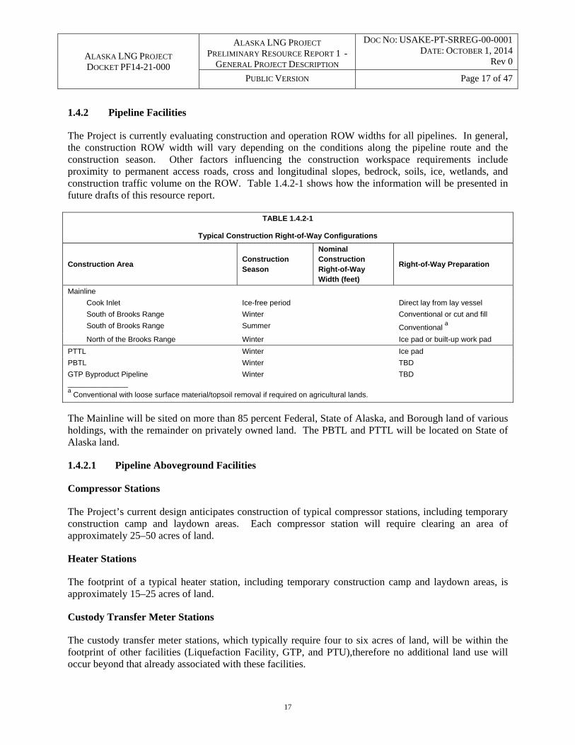
1.4.2 Pipeline Facilities
The Project is currently evaluating construction and operation ROW widths for all pipelines. In general, the construction ROW width will vary depending on the conditions along the pipeline route and the construction season. Other factors influencing the construction workspace requirements include proximity to permanent access roads, cross and longitudinal slopes, bedrock, soils, ice, wetlands, and construction traffic volume on the ROW. Table 1.4.2-1 shows how the information will be presented in future drafts of this resource report.
TABLE 1.4.2-1
Typical Construction Right-of-Way Configurations
Construction Area Construction Season
Nominal Construction Right-of-Way Width (feet)
Right-of-Way Preparation
Mainline
Cook Inlet Ice-free period Direct lay from lay vessel
South of Brooks Range Winter Conventional or cut and fill
South of Brooks Range Summer Conventional a
North of the Brooks Range Winter Ice pad or built-up work pad
PTTL Winter Ice pad
PBTL Winter TBD
GTP Byproduct Pipeline Winter TBD ________________ a Conventional with loose surface material/topsoil removal if required on agricultural lands.
The Mainline will be sited on more than 85 percent Federal, State of Alaska, and Borough land of various holdings, with the remainder on privately owned land. The PBTL and PTTL will be located on State of Alaska land.
1.4.2.1 Pipeline Aboveground Facilities
Compressor Stations
The Project’s current design anticipates construction of typical compressor stations, including temporary construction camp and laydown areas. Each compressor station will require clearing an area of approximately 25–50 acres of land.
Heater Stations
The footprint of a typical heater station, including temporary construction camp and laydown areas, is approximately 15–25 acres of land.
Custody Transfer Meter Stations
The custody transfer meter stations, which typically require four to six acres of land, will be within the footprint of other facilities (Liquefaction Facility, GTP, and PTU),therefore no additional land use will occur beyond that already associated with these facilities.
ALASKA LNG PROJECT DOCKET PF14-21-000
ALASKA LNG PROJECT PRELIMINARY RESOURCE REPORT 1 -
GENERAL PROJECT DESCRIPTION
DOC NO: USAKE-PT-SRREG-00-0001 DATE: OCTOBER 1, 2014
Rev 0
PUBLIC VERSION Page 18 of 47
18
Mainline Block Valves (MLBVs)
Construction and operation of the MLBVs will take place within the pipeline ROW, compressor station, or meter station site. Therefore, no additional land use will occur beyond that already associated with these facilities. However, permanent access to MLBVs will be determined as the Project is designed and may include new or improved access roads and/or helipads outside of a compressor or meter station site.
Launchers and Receivers
Construction and operation of launchers and receivers will occur within a proposed aboveground facility site (e.g., GTP, compressor stations, and meter stations) such that no additional land use will occur beyond that already associated with these facilities. However, the engineering team is evaluating the potential need for additional land use associated with setting launchers and receivers at the shore crossings of Cook Inlet.
Off-Take Interconnection Points
Construction of an off-take interconnection point will occur within the pipeline ROW or a compressor or meter station site. Therefore, no additional land use will occur beyond that already associated with these facilities.
Cathodic Protection Facilities
The land required for cathodic protection facilities (ground beds and rectifiers) will primarily be within the pipeline ROW or a compressor station or meter station site where possible. Test lead posts will also be located along the permanent ROW. The requirement for any additional land use associated with these facilities is under evaluation.
Aboveground Pipeline Construction
The support structures and any permanent access roads will be constructed within the permanent ROW for the pipeline.
1.4.2.2 Pipeline Associated Infrastructure
Additional Temporary Workspace (ATWS)
ATWS will be located outside of, but adjacent to, the pipeline construction ROW where construction activities cannot be executed safely within the ROW or where extra equipment is required (e.g., waterbody, road, utility, and other crossings; at bends and timber storage locations; and in other situations). Each individual location requiring ATWS will be assessed and sized appropriately to account for terrain, soil conditions, site configuration, site-specific construction method, and construction season.
Access Roads
Existing roads and newly constructed access roads will be utilized during the construction and operation phases of the Project. North of Livengood, construction crews and operations staff will utilize the gravel and access roads that were built for TAPS and for the Denali highway, where appropriate.
ALASKA LNG PROJECT DOCKET PF14-21-000
ALASKA LNG PROJECT PRELIMINARY RESOURCE REPORT 1 -
GENERAL PROJECT DESCRIPTION
DOC NO: USAKE-PT-SRREG-00-0001 DATE: OCTOBER 1, 2014
Rev 0
PUBLIC VERSION Page 19 of 47
19
South of Livengood, the current design requires an access road approximately every 10 miles of pipeline from the nearest existing public or private road to the construction ROW . This access may include improvements to existing roads (e.g., widening, gravel fill, culverts, reduce curvature of the road) or construction of new roads. For winter construction, access roads will be made of an ice and gravel combination.
Helipads
Each helipad will be constructed of borrow material with dimensions of approximately 100 feet by 100 feet. All affected land will be within the construction camp site and/or the permanent operations ROW of the pipeline or a compressor station. Therefore, no additional land use will occur beyond that already associated with these facilities. Approximately 24 potential temporary and 32 potential permanent helipad locations north of Livengood have been identified to date.
Airstrips
The potential need to upgrade any existing public airports and private airfields for the Project is under evaluation.
Construction Camps, Pipe Storage Areas, and Contractor Yards
Temporary construction camps, pipe storage yards, and contractor yards will be built at various locations to support pipeline construction. In general, construction camps will range in size from 10–40 acres, depending on the number of workers housed there. Pipe storage yards will range in size from 20–25 acres and be spaced about every 20 miles along or near the pipeline construction ROW. In some cases, a pipe yard and contractor yard may be collocated together and/or with a construction camp, depending on available acreage, access, and topography. To the extent possible, these sites will be located on previously disturbed areas.
Temporary construction camps will be self-contained, as well as operated and maintained, throughout the pipeline and facilities construction period. Some camps will be relocated as the construction work progresses. In addition to housing facilities, the camps will typically be equipped with appropriate emergency medical facilities, electrical power generation, fuel storage, facilities for sewage gathering or treatment, and waste incineration and management facilities. Depending on availability, potable water for the camps will be piped or trucked in or water wells may be drilled at the camp location. Pioneer camps (50–125 personnel) will support development of Project infrastructure, clearing, and isolated construction operations (e.g., major river crossings and material site locations). Generally, these camps will be located at sites planned for other uses such as pipeline and facility camps, pipe storage areas, contractor yards, and the pipeline construction ROW.
Compressor and heater camps (75–250 personnel) will support heater station and compressor station construction. Generally, these camps will be located at facility construction sites. Camps established for construction of compressor stations will be situated as near as possible to the station that the crews will be constructing. These camps will likely consist of approximately 20-50 portable modules that may be moved from location to location during the course of construction.
ALASKA LNG PROJECT DOCKET PF14-21-000
ALASKA LNG PROJECT PRELIMINARY RESOURCE REPORT 1 -
GENERAL PROJECT DESCRIPTION
DOC NO: USAKE-PT-SRREG-00-0001 DATE: OCTOBER 1, 2014
Rev 0
PUBLIC VERSION Page 20 of 47
20
Pipeline camps (750–1,600 personnel) will support pipeline and aboveground facilities construction. These larger camps will generally be collocated with contractor yards and some of the pipe storage areas. Each new camp will consist of approximately 250–500 portable modules and may be moved from spread to spread up to three times during the course of pipeline construction.
Pipe storage areas will temporarily house the pipe to be installed. Pipe storage areas will be either standalone or collocated with camps and contractor yards. Contractor yards will be used for construction staging, storing materials, equipment rig-up, setting up temporary construction trailers, fabrication work, safety and environmental training, equipment repair, and contract administration.
During post-construction reclamation, all temporary camps, pipe storage areas, and contractor yards will be disassembled and surface facilities removed unless other arrangements are made with the landowner or land managing agency. Gravel pads installed as part of camp or yard construction will be left in accordance with land use agreements.
Temporary Docks
The potential need for construction of temporary dock facilities along the north shore of Cook Inlet is under evaluation. The potential temporary dock facilities would support the transportation of pipe, construction equipment, and other materials to this remote section of the Mainline during the construction phase.
Material Sites
Various materials (e.g., sand, gravel, and stone) will be required for Project activities, including base material for compressor station sites, temporary construction facilities, access roads and other uses. Material may also be used during construction for concrete production, temporary laydown, equipment staging, and other uses. The material required for these facilities will be obtained from material sites that are either existing or will be developed for the Project. At the conclusion of pipeline construction activities, material sites will either be used for other projects, such as for road construction administered by ADOT&PF, or closed as per land use agreements and regulatory requirements. In general, a material site is required approximately every 20 miles of pipeline ROW to support construction.
1.4.3 Gas Treatment Plant
It is estimated that approximately 1,000 acres will be used during construction of the GTP and all ancillary and associated facilities. Of the approximately 1,000 acres, operations will impact 200–300 acres. The GTP and associated facilities will be located on State of Alaska land on the North Slope.
1.4.3.1 GTP Associated Infrastructure
Module Staging Area
Land required for the module staging area will impact 20–40 acres during construction. Following construction, the module staging area will be maintained for additional equipment deliveries during operations.

ALASKA LNG PROJECT DOCKET PF14-21-000
ALASKA LNG PROJECT PRELIMINARY RESOURCE REPORT 1 -
GENERAL PROJECT DESCRIPTION
DOC NO: USAKE-PT-SRREG-00-0001 DATE: OCTOBER 1, 2014
Rev 0
PUBLIC VERSION Page 21 of 47
21
Access Roads
Workers will use existing, modified, and new roads to access the GTP site from the West Dock. A total of 100–150 acres of land will be used during construction and operation of access roads associated with the GTP. This includes two to five acres to widen the existing causeway road from the West Dock’s Dock Head 2, 15–20 acres to widen an existing road in the PBU, and approximately 100 acres to construct new north and south roads.
Material Sites
The sand and gravel required for construction of the GTP and related facilities will be obtained from existing material sites and/or the water reservoir location (see below).
West Dock Modifications
Modifications to the West Dock’s Dock Head 2 facilities will require gravel fill that will increase the dock head by approximately 25 acres. The existing channel from Dock Head 2 will need to be widened and deepened (out to the 16-foot-depth contour) to accommodate the larger vessels for module offloading.
Water Reservoir
A water reservoir used for the supply of firewater, potable water, and process makeup water will be constructed on the north side of the Putuligayuk River. Water will be withdrawn from the Putuligayuk during the spring break-up period and stored in the reservoir for use during the year.
1.5 CONSTRUCTION SCHEDULE AND PROCEDURES
1.5.1 Project Construction Schedule
The Applicants will request that FERC issue authorization to site, construct, and operate the Project no later than July 2018, with construction to commence between late 2018 and early 2019. The construction and startup period is approximately seven years.
1.5.1.1 Liquefaction Facility Construction Schedule
Liquefaction Facility site preparation will commence after acquisition of all necessary property rights, permits and authorizations, and construction will generally proceed as follows:
Site preparation activities and infrastructure development will begin in 2019 and are currently planned to occur throughout a two-year period.
The major facilities (for the GTP and LNG Plant) will be built as modules and delivered in a series of sealifts from 2022–2024 (and tied in upon delivery). Major site facilities, including the LNG storage tanks, will be erected at site over the course of three to four years.
On-site fabrication of the modules will take place over the seven-year time period.
Commissioning of the tanks and processing units will occur as gas is delivered to the site.
ALASKA LNG PROJECT DOCKET PF14-21-000
ALASKA LNG PROJECT PRELIMINARY RESOURCE REPORT 1 -
GENERAL PROJECT DESCRIPTION
DOC NO: USAKE-PT-SRREG-00-0001 DATE: OCTOBER 1, 2014
Rev 0
PUBLIC VERSION Page 22 of 47
22
1.5.1.2 Mainline Construction Schedule
Mainline site preparation will commence after acquisition of all necessary property rights, permits and authorizations, and construction will generally proceed as follows:
The Mainline infrastructure construction and logistical support will begin in 2019. The construction of the Mainline is currently planned to occur over a three-year period using a number of different construction spreads in winter and summer seasons.
Compressor stations, meter stations, heater stations, and other associated pipeline infrastructure will also be constructed during this time.
1.5.1.3 Gas Treatment Plant (GTP) Construction Schedule
GTP site preparation will commence after acquisition of all necessary property rights, permits and authorizations, and construction will generally proceed as follows:
Infrastructure construction activities are currently planned to start in the winter of 2019. The majority of this work will be associated with preparation of granular material and construction of dock modifications, gravel pads, and access roads to support the aboveground facility construction efforts.
Preparation for GTP construction is anticipated to start in 2019 with other infrastructure
construction. Modules are planned for completion at the fabrication sites in order to reduce the time required for facility installation on the North Slope. Four consecutive summer sealift seasons and corresponding construction periods are planned. Sealifts one, two, three, and four will arrive on the North Slope during 2021 through 2024. As installation of the modules is completed each year, the facilities will be released to the facility operations team for commissioning and startup.
Due to the size of the modules required for the GTP, large ocean going vessels will be utilized.
Dredging of the shallow waters at Prudhoe Bay will be required to prepare a channel deep enough for the vessels. Both summer and winter dredging options are being evaluated at this time. Initial dredging will occur from one to two years before the first sealift.
1.5.1.4 Other Pipeline Construction Schedule
Site preparation for the other Project pipelines will commence after acquisition of all necessary property rights, permits and authorizations. Construction work on the PTTL and the PBTL will commence in the 2021-2022 timeframe.
1.5.2 Project Construction Procedures
Except where otherwise authorized, the proposed facilities will be designed and constructed in accordance with all applicable federal, state and local regulations, permits, and industry-recognized standards. Applicable federal regulations include 49 C.F.R. Part 193, Liquefied Natural Gas Facilities: Federal Safety Standards; 49 C.F.R. Part 192, Transportation of Natural Gas and Other Gas by Pipeline: Minimum Federal Safety Standards; 18 C.F.R. Part 2.69, Guidelines To Be Followed by Natural Gas

ALASKA LNG PROJECT DOCKET PF14-21-000
ALASKA LNG PROJECT PRELIMINARY RESOURCE REPORT 1 -
GENERAL PROJECT DESCRIPTION
DOC NO: USAKE-PT-SRREG-00-0001 DATE: OCTOBER 1, 2014
Rev 0
PUBLIC VERSION Page 23 of 47
23
Pipeline Companies in the Planning, Clearing and Maintenance of Rights-of Way and the Construction of Aboveground Facilities; 33 C.F.R Part 127, Waterfront Facilities handling Liquefied Natural Gas and Liquefied Hazardous Gases; and ASME B31.3.
Alaska presents unique construction and operating conditions. As a result, modified procedures will be proposed where the measures contained in the FERC Erosion Control, Revegetation, and Maintenance Plan (FERC Plan) and Wetland and Waterbody Construction and Mitigation Procedures (FERC Procedures) are not considered applicable, are technically infeasible, or are unsuitable due to Alaska conditions. The Applicants will prepare and implement a Project-specific Erosion Control, Revegetation, and Maintenance Plan (the Applicants’ Plan) and Wetland and Waterbody Construction and Mitigation Procedures (the Applicants’ Procedures). The Applicants’ Plan and Applicants’ Procedures are being developed using the 2013 versions of the FERC Plan and FERC Procedures. The Applicants’ Plan and Applicants’ Procedures will build upon the FERC Plan and FERC Procedures and applicable permit conditions using a “toolbox” approach consistent with the FERC guidance. The toolbox will contain a set of best management practices. 1.5.2.1 Construction Logistics
Logistics activities include the transporting of personnel, equipment, construction materials, and supplies to construction sites via sea, road, rail, and/or air transportation infrastructure. Although site preparation and construction will be phased to lessen impacts to local infrastructure and communities, the size of this Project and duration of construction will require detailed planning with state and local authorities to minimize impacts to existing infrastructure. Logistics activities will begin prior to Project infrastructure construction subject to any and all necessary regulatory approvals.
Logistics Timeline
Construction contractors are expected to mobilize and demobilize construction equipment to and from specific construction sites from late 2018/early 2019 through 2025. Stockpiling of material and staging of construction equipment is anticipated to begin approximately one year prior to construction on facilities that already exist.
Logistics Plans
Detailed logistics plans developed prior to construction will address the following activities:
Plans for securing, transporting, lodging, and feeding the construction workforce;
Transportation of material and equipment from existing marine facilities to the individual spread storage/laydown yards, including coordination through the various staging areas;
Transportation of construction equipment and rolling stock from point of entry premises and initial contractor storage;
Ground and air transportation of Liquefaction Facility, pipeline, and GTP crews and supervisors;
Transportation of and coordination with camps and associated camp material and equipment provided by the camp suppliers;
ALASKA LNG PROJECT DOCKET PF14-21-000
ALASKA LNG PROJECT PRELIMINARY RESOURCE REPORT 1 -
GENERAL PROJECT DESCRIPTION
DOC NO: USAKE-PT-SRREG-00-0001 DATE: OCTOBER 1, 2014
Rev 0
PUBLIC VERSION Page 24 of 47
24
Transportation of Liquefaction Facility and GTP modules from modular fabrication sites to Cook Inlet and Prudhoe Bay, respectively;
Transportation of supplies and consumables during construction, including fuel;
Return of construction equipment, rolling stock, storage tanks, camp modules, surplus materials, and equipment for salvage at the completion of the Project;
Location and development of material sites and the methods for transporting materials to processing and stockpiling areas and finally, to work sites;
Customs clearance procedures;
Execution of the approved Project Waste Management Plan for construction wastes (hazardous and non-hazardous);
Seasonal ice-window open and close dates;
Road traffic management;
Integrated transportation schedule for Project-wide marine transportation in U.S. waters; and
Response plans for accidents or spills.
1.5.2.2 Aboveground Facility Construction Procedures
Liquefaction Facility
Initial construction activities will focus on the infrastructure required to support the actual construction of the Liquefaction Facility. This will include:
The installation of a pioneer camp to support the early work;
The excavation and stockpiling of gravel for the roads and pads;
Building or relocating access roads to the site;
Site clearing and topsoil removal;
Earthworks to support the facility construction;
A gravel pad and foundations for the main construction camp;
Installation of underground and overhead utilities;
Construction of a MOF and laydown areas;

ALASKA LNG PROJECT DOCKET PF14-21-000
ALASKA LNG PROJECT PRELIMINARY RESOURCE REPORT 1 -
GENERAL PROJECT DESCRIPTION
DOC NO: USAKE-PT-SRREG-00-0001 DATE: OCTOBER 1, 2014
Rev 0
PUBLIC VERSION Page 25 of 47
25
Construction of a channel from the 12-foot bathymetry line to the future MOF;
Construction of a dock to support vessels and tugs;
AD for bulk materials;
Construction dock;
Construction of an office, warehouses, and fabrication shops to support construction;
Installation of the main construction camp; and
Installation of security fencing and security systems required to support construction.
Once the site work has been completed, a concrete batching plant can be erected along with other infrastructure necessary to support construction.
LNG Plant
Major components of the LNG trains and ancillary infrastructure (e.g., power generation) will be delivered to the site as modules, with other infrastructure (e.g., LNG storage tanks) built on the site. Structural steel work and assembly of the LNG train modules will be followed by pipe work and installation of mechanical equipment, including gas turbines, electric motors, and compressors. Electrical and instrumentation is the final major work scope installed before the Liquefaction Facility is commissioned.
The construction of the LNG storage tanks will be in parallel with the LNG plant construction. The tanks will be built on a concrete foundation and floor. Reinforced concrete for the outer containment walls may be constructed on site using methods to ensure a leak-tight structure. Alternate construction methods will also be studied during the pre-FEED effort. The LNG tank roof will be constructed at ground level and then lifted into position. Bridging sections will then be inserted between the main body of the roof and the outer cylindrical wall. Tank filling and equipment for LNG carrier loading systems will be installed on top of the tanks. The primary containment or membrane will undergo hydrostatic testing at the completion of construction. The primary containment or membrane will be cleaned and dried following hydrostatic testing and may be pre-cooled using a small amount of LNG.
It is expected that the Liquefaction Facility will require fresh water during construction, as well as materials and disposal sites to handle construction debris during construction. The pre-FEED studies will examine the complete construction plan, logistics requirements, and infrastructure needs to support construction of the facilities. Temporary support facilities (e.g., construction offices, workshops, warehouses, parking lots, and portable toilets) will be installed on the plant site during the construction phase of the Project.
Marine Terminal
The trestle(s) and LNG export berths will be supported on piles driven into the seafloor. The LNG export berths will be built at the seaward end of the trestle(s) after completion. One method of construction currently being evaluated uses a jack-up or vessel-mounted crane to place precast concrete or steel pile
ALASKA LNG PROJECT DOCKET PF14-21-000
ALASKA LNG PROJECT PRELIMINARY RESOURCE REPORT 1 -
GENERAL PROJECT DESCRIPTION
DOC NO: USAKE-PT-SRREG-00-0001 DATE: OCTOBER 1, 2014
Rev 0
PUBLIC VERSION Page 26 of 47
26
caps at the top of the piles, where they will be fixed and welded into place. The breasting and mooring dolphins will also be built during this time. The remainder of the catwalks, decking, and headstock systems will be installed, followed by the installation of the mechanical and electrical works and utilities and loading arms. The jack-up or vessel-mounted crane will lift the pre-fabricated trestle and berth sections into position.
The potential need to dredge the Marine Terminal or channel to the Marine Terminal is under evaluation. A jack-up vessel or floating crane will drive piles for the berth and dolphin piles. Vessel types will be confirmed in development of the execution strategy. Performance criteria, including lift capacity, payload, bearing pressure, bulk product requirements, will also be determined during pre-FEED. It is not envisioned that this facility will have re-fueling or bunker offloading capabilities for marine diesel fuel.
1.5.2.3 Pipeline Construction Procedures
The following provides a brief description of typical construction procedures that will be implemented. These procedures will be modified as necessary to comply with site-specific environmental considerations.
Surveying
Limits of ROW boundaries and facilities will be staked, including construction and ATWS areas that will require the use of permitted access roads. This includes the staking and/or exclusion fencing of known archaeological sites, select wetland areas, and water crossing boundaries, as well as other areas (e.g., environmentally sensitive) requiring protection during the construction process. Existing underground utilities will be located and flagged prior to construction.
Surveying and staking activities will also be required during construction to mark the locations of utility crossings and facility placement within sites. During construction, as-built surveys will be conducted to document as-built information.
Clearing
Clearing activities will typically occur in the winter season prior to each scheduled construction season and will include removing trees and brush. Vegetation will be removed mainly using heavy equipment, including feller-bunchers, mulchers, de-limbers, hydro-axes, and cable and grapple skidders. Some handwork with power saws will also be required. Except for some sites with aboveground facilities, the cleared work space will generally not be grubbed; that is, root structures will not be removed until the season of construction. At aboveground sites, a gravel pad is usually installed on a leveled area. The clearing activity for winter construction may also involve snow management.
Temporary erosion control mitigation measures will be installed in accordance with the Applicants’ Plan, and merchantable timber may be stored on, or immediately adjacent to, the work area in authorized storage areas. The burning or mulching of non-salvaged vegetation will be completed following clearing activities in accordance with agency criteria, permitting and timing constraints.
ALASKA LNG PROJECT DOCKET PF14-21-000
ALASKA LNG PROJECT PRELIMINARY RESOURCE REPORT 1 -
GENERAL PROJECT DESCRIPTION
DOC NO: USAKE-PT-SRREG-00-0001 DATE: OCTOBER 1, 2014
Rev 0
PUBLIC VERSION Page 27 of 47
27
Grading
Work surface grading is necessary to level the work surface for the safe use of heavy equipment during construction. Grading is also necessary to level side slopes across the work surface and to reduce the angle of longitudinal slopes along the work surface.
The surface layer of native material will normally be bladed to one or both sides of the work area and stored in windrows for re-use. For summer pipeline construction in actively cultivated or rotated crop lands, topsoil may be stripped from the entire width of the ROW and moved to one or both sides of the ROW, stored in windrows, and segregated from stockpiled mineral soils and trench spoil. Additional temporary environmental and erosion control mitigation measures will also be utilized as required in accordance with the Applicants’ Plan.
Winter season grading activities are enhanced by taking advantage of frozen soil conditions to support construction equipment and vehicles. For thaw-stable soils, ROW preparation activity will begin by driving frost into the ground so that heavy construction equipment will be supported. For thaw-sensitive soils, initial preparation activities may include installation of a gravel or snow/ice working surface. Snow/ice working surfaces will be applied in thaw-sensitive tundra areas on the North Slope. Grade cuts will be required on steeper slopes. During winter construction, snow and loose surface material may be windrowed over the trench line to reduce seasonal or mechanical penetration of frost. This material is bladed away just prior to trenching activities.
For access roads, laydown yards, storage yards, the pipeline ROW, and other temporary work areas during winter seasons, wetlands or soils that are otherwise unstable due to high moisture content will be frost packed. Frost packing improves surface bearing capacity so that heavy equipment can be safely supported. In some instances, the use of construction mats, log corduroy, and/or geotextile products and fill may be required to bridge a wet or otherwise unstable area to ensure that heavy construction equipment and support vehicles can pass.
In areas where rock at grade is encountered, the surface will be ripped with ripper tractors if possible. If it cannot be ripped, it will be drilled and blasted after removal of any loose surface material. Grading of rock areas may be undertaken a season or more in advance of construction.
Ice and Snow Work Pads and Access Roads
In certain tundra and wetland areas, winter work pads will be required. Winter work pads and roads may be constructed of compacted snow, ice aggregate, mixtures of snow and water, manufactured snow, or ice created by flooding the tundra surface to achieve a design elevation.
Access roads will be developed for access to approved water sources to obtain water and ice for manufacturing ice roads, developing the winter work pad on the ROW, acquiring ice aggregate from the frozen surfaces of approved waterbodies, and filling depressions on the ROW and on more conventional winter access roads. Once in use, winter work pads and access roads will require maintenance to repair damage caused by tracked equipment. Maintenance of work pads will include adding snow, ice and water, grading, and in some cases, adding ice aggregate as fill.
Work crews will decommission winter snow and ice work pads and roads at the end of each winter season in accordance with land use permits.
ALASKA LNG PROJECT DOCKET PF14-21-000
ALASKA LNG PROJECT PRELIMINARY RESOURCE REPORT 1 -
GENERAL PROJECT DESCRIPTION
DOC NO: USAKE-PT-SRREG-00-0001 DATE: OCTOBER 1, 2014
Rev 0
PUBLIC VERSION Page 28 of 47
28
Erosion Control during Construction
Work sites will be stabilized during construction to reduce surface erosion and siltation. Stabilization work will be done using best management practices outlined in the Applicants’ Plan, in which installation and maintenance of temporary and permanent environmental mitigation measures will depend on site-specific conditions and needs. For erosion control efforts, this may include installation of diversion berms, surface drainage ditches, French drains, silt fences, erosion-control matting, straw or synthetic bales, and other means that have traditionally been used to mitigate and control surface erosion.
Erosion control measures will be left in place and repaired, replaced, and supplemented as required through the end of construction to mitigate surface soil erosion that could occur as a result of the spring thaw and snow melt or summer precipitation events. Additional information regarding erosion and sediment control measures will be provided in the Applicants’ Storm Water Pollution Prevention Plan.
Stringing
Hauling and stringing (i.e., laying) of individual pipe segments (also referred to as “joints”) will take place as access to the ROW progresses. The joints will be laid next to the trench as access to the ROW progresses. In certain trench soil conditions, such as those requiring drilling and blasting, stringing will take place after trenching. Individual pipe lengths are nominally 40, 60, or 80 feet in length. Pipe will normally be transported for stringing by trucks with trailers. In some areas of challenging terrain, tracked pipe carriers or helicopters may be utilized.
Bending
Pipe bending operations will follow pipe stringing. The bending crew will bend the pipe to fit the vertical profiles and horizontal alignments of the graded ROW. Typically, manufactured fittings or hot bends will be used where pipe cannot be cold-bent in the field to create the desired angle.
Hydraulic pipe benders will be pulled along the ROW by a tow tractor and positioned at intervals along the ROW. At each location, individual pipe joints will be carried to the bending machine by a pipe-layer, inserted into the pipe bender, and bent to the required angle as identified by the bending engineer.
Production Welding
Pipe joints will be aligned and set up for field production welding. Generally, production welding will be done using a mechanized welding system, however, manual (“stick” welding) and semi-automatic welding may also be used. Qualified and certified non-destructive examination inspectors will perform non-destructive testing of all welds. Welds that do not meet specification will be repaired or cut-out and replaced in accordance with specifications and applicable code requirements.
Joint Coating
Following welding and non-destructive testing, field or girth welds will be coated in accordance with field coating specifications. The field joint coating materials and application process will be appropriately matched to the pipe coating applied in coating mills. The coating process will be performed in compliance with a Project-specific coating procedure and specification.
ALASKA LNG PROJECT DOCKET PF14-21-000
ALASKA LNG PROJECT PRELIMINARY RESOURCE REPORT 1 -
GENERAL PROJECT DESCRIPTION
DOC NO: USAKE-PT-SRREG-00-0001 DATE: OCTOBER 1, 2014
Rev 0
PUBLIC VERSION Page 29 of 47
29
Each section of welded pipe will be inspected to locate any coating flaws after field joint coating is complete and prior to lowering in. Pipe coating damage identified will be repaired in accordance with an approved Project-specific procedure and specification.
Trenching
The pipeline trenches will be excavated with bucket wheel or chain trenching machines, or track-mounted excavators. Track-mounted mechanical rippers, rock hammers, or rock trenchers will be used to fracture and excavate rock or frozen soil. Drilling and/or blasting will be required where other means are not practical.
In both summer and winter construction, pipe will typically be welded and girth weld coated ahead of trenching, except where blasting is required. This sequence results in the trench remaining open for only a short time before the welded pipe sections are lowered in, making the trench less likely to fill with snow and less likely that the spoil material will freeze. Blasting, if required, will normally take place prior to stringing and welding. Pipe will be buried with depths of cover meeting the requirements of 49 C.F.R. Part 192.
Lowering In, Tie-ins, and Backfilling
Before welded pipe sections are lowered into the trench, the trench will be inspected to ensure that it is free of rocks and other debris that could damage the pipe or its protective coating. Dewatering or removal of snow may be necessary to allow for inspection of the trench bottom. In rock trench conditions or where soils include the presence of frozen soil lumps, boulders, or cobbles; foam pillows or imported select fill bedding material (e.g., sand or soil fines) will be placed on the trench bottom before the pipe sections are lowered in. Suitable bedding and padding material will be placed around the pipe to protect the pipe and coating from damage. Other pipe protection measures such as a rock-shield material may be installed before the lowering in of pipe strings.
After the pipe sections are lowered into the trench, tie-in welds will be performed to join together welded sections of pipe. Similar to production welding discussed above, tie-in welds will be performed in accordance with qualified weld procedures and non-destructively examined in accordance with qualified procedures.
Testing and Final Tie-Ins
After backfilling, the pipeline will be pressure tested. Sections of pipeline to be tested as single segments will be determined according to water availability and terrain contours. Water for pressure testing will be obtained from approved water sources and may be treated with an appropriate biocide depending on hydrostatic test holding times. During winter conditions, hydrostatic testing will likely be performed using heated water or water mixed with freeze-depressant additives. If additives are used, the hydrostatic test water will be distilled or treated to separate the additives from the water prior to discharge or will be disposed using an approved disposal method. Sheltering and heating exposed pipe and test heads during winter conditions is required.
ALASKA LNG PROJECT DOCKET PF14-21-000
ALASKA LNG PROJECT PRELIMINARY RESOURCE REPORT 1 -
GENERAL PROJECT DESCRIPTION
DOC NO: USAKE-PT-SRREG-00-0001 DATE: OCTOBER 1, 2014
Rev 0
PUBLIC VERSION Page 30 of 47
30
After completion of the pressure test, the water will be discharged in accordance with applicable permits. Once the pipeline is dewatered, it will be cleaned and dried. After all testing is complete, the test heads will be removed and the final tie-ins completed.
Cleanup and Reclamation
In both summer and winter construction, initial cleanup will begin after backfilling of the trench is complete. Cleanup will continue as weather and ground surface conditions allow, in accordance with the Applicants’ Plan and Applicants’ Procedures, and will continue until all permit conditions have been met. Winter cleanup activities and restoration work will be completed during subsequent winter seasons, as necessary; however, final cleanup may also occur during summer months if access roads and the ROW are drivable. Summer remedial work may be required following winter construction to reestablish erosion control measures and address surface water drainage or final grade issues.
Construction debris will be recycled or disposed of at approved off-ROW disposal sites. Surface drainage patterns will be reestablished. In most areas, a crown of trench backfill material will be centered over the trench to compensate for settling of the backfill material as it consolidates. Surface cross-drainage patterns will be reestablished where the trench line has been crowned.
Segregated, loose surface materials removed during winter construction before grading operations and stripped topsoil/loose surface material set aside during summer pipeline construction will be spread over the surface of the ROW. Permanent erosion control devices appropriate for the application will be installed. Afterwards, disturbed and non-cultivated work areas will be seeded using approved seed mixes in accordance with Project-specific revegetation and reclamation plans.
Markers showing the location of the pipeline will be installed at fence and road crossings in order to identify the owner of the pipeline and convey emergency contact information in accordance with applicable governmental regulations and Project-specific specifications. Special markers providing information and guidance to aerial patrol pilots will also be installed.
Marine Pipe Lay (Cook Inlet)
For crossing of Cook Inlet, marine pipeline construction procedures used throughout the world, and modified for this unique environment, will be used. During pre-FEED, the engineering contractor will assess the environmental, regulatory, engineering, and construction factors to determine the proper construction methods, timing, and equipment necessary to safely and effectively build the pipeline across Cook Inlet.
The current design weights the pipeline (concrete coating, set on weights, and/or other means) for placement directly on the seafloor bottom. Where utilities exist in Cook Inlet (e.g., other pipelines or fiber optic lines), they will be located and a method to ensure separation will be designed in consultation with the utility owner. Stages of marine pipeline construction are outlined below.
Pre-Sweep
Pre-lay seabed preparation may be required. Pre-sweep activities potentially include debris and rock removal, and installing hardware to enable the crossing construction of existing fiber optic or other utilities by the Mainline.
ALASKA LNG PROJECT DOCKET PF14-21-000
ALASKA LNG PROJECT PRELIMINARY RESOURCE REPORT 1 -
GENERAL PROJECT DESCRIPTION
DOC NO: USAKE-PT-SRREG-00-0001 DATE: OCTOBER 1, 2014
Rev 0
PUBLIC VERSION Page 31 of 47
31
Pipelay
Using a specialty vessel fitted and used for pipeline construction, the pipeline will be welded and inspected, field joint coated, and equipped with cathodic protection on the vessel before it is lowered to the seafloor. The vessel is held in place with an array of anchors. When the pipeline is lowered to the seafloor, the vessel is advanced in a slow and controlled pace by retracting front anchor lines and paying out rear anchor lines while maintaining the pipelay tension. Once the anchor line stroke is reached, anchor handing vessels will pick up and move anchors during this operation.
Landfalls
There are four landfalls along the pipeline route being considered as part of the west (preferred) and east (alternative) routes south of Trapper Creek. Depending on which route is ultimately selected, there are two landfalls associated with the northern side of Cook Inlet and the western shore of the Kenai Peninsula, and two landfalls associated with the western side of Cook Inlet and western shore of the Kenai Peninsula near Nikiski. Agency guidance to date has indicated that the pipeline should cross where there are bluffs along Cook Inlet and not across shallow mud flats. Current routing has incorporated these constraints into the design.
Methods for installing the pipeline across the landfall include open-cut trenching and horizontal directional drilling (HDD) under the shoreline. Open cut landfall involves the pipelay vessel positioning offshore, typically between a half and one mile, and with the vessel stationary, pipe is pulled by linear winches located on the beach through a pre-dredged trench. HDD is a method of landfall construction that is also used for river and other crossings. The HDD process has three distinct stages:
An initial pilot hole is drilled with a down-hole navigation package, relaying the position and depth to the drilling crew;
The diameter of the hole is increased using different types of reamers depending upon the ground conditions; and
When the hole is opened to a suitable diameter, the pipeline is pulled into position.
Micro-tunneling methods are also under evaluation.
Wetland Crossings
Because of the large expanses of wetlands in Alaska, it is not feasible for the Project to avoid crossing wetlands or to treat them as isolated features on a case-by-case basis. The construction techniques used in wetlands will, therefore, depend on site-specific conditions at the time of construction, including season and weather conditions, the degree of soil saturation, presence and extent of permafrost, soil stability, and wetland type. The Applicants’ Procedures will identify where conventional upland cross-country construction will occur and where modifications to the conventional techniques will be needed.
Summer Conditions
Summer construction in wetlands where ROW grading (i.e., cuts and/or fills) is required, and where sub-soils can support construction equipment, will proceed as described in Section1.5.2.3. For low-strength
ALASKA LNG PROJECT DOCKET PF14-21-000
ALASKA LNG PROJECT PRELIMINARY RESOURCE REPORT 1 -
GENERAL PROJECT DESCRIPTION
DOC NO: USAKE-PT-SRREG-00-0001 DATE: OCTOBER 1, 2014
Rev 0
PUBLIC VERSION Page 32 of 47
32
soils that do not support construction equipment without adverse impacts such as soil mixing or deep rutting, alternative wetland crossing techniques will be considered. The Applicants’ Procedures will provide further detail for the proposed summer construction and reclamation of wetlands as appropriate to site conditions.
Winter Conditions
Winter construction in wetlands will proceed as described in Section 1.5.2.3. Even though sections of the pipeline will be constructed during winter months, it is expected that under certain conditions the subsoil or work surface will not be frozen or trafficable. If the subsoil cannot support construction equipment without adverse impacts, such as soil mixing or deep rutting, an alternate crossing method will be considered. The Applicants’ Procedures will provide further detail for the proposed winter construction and reclamation of wetlands as appropriate to site conditions.
Waterbody Crossings
Perennial waterbodies; seasonally intermittent watercourses; and other permanent waterbodies, such as ponds and North Slope lakes; will be crossed. Waterbodies will be crossed using a number of different crossing methods described below, and will be described in more detail in the Applicants’ Procedures. Crossing installations will be performed in accordance with construction specifications and all terms and conditions included in each crossing permit. For those waterbodies that are dry or frozen to the bottom when crossed, the Applicants propose to use conventional upland cross-country construction techniques and procedures.
Proposed crossing methods based on each waterbody’s characteristics and site-specific conditions will be identified as detailed below:
If the waterbody is dry or frozen to the bed, the Applicants will cross the waterbody using an open-cut (OC) crossing method;
If the waterbody is flowing, assess the type of fish and fish habitat present within the affected reach and determine whether an OC timing window is available;
If the potential fisheries impact is rated as acceptable, and if an OC timing window is available, and the in-stream work can be completed within the timing window, the Applicants will proceed with the installation using the OC crossing method;
If an OC timing window is not available or is too short to complete the in-stream work, the use of isolated (dry) crossing methods will be considered; and
If the potential fisheries impact is rated as not acceptable and if isolated crossing methods are not feasible or appropriate, then consideration will be given to using a trenchless crossing method such as HDD (a minimum practical length of 1,700 to 1,900 feet on level terrain is required for using the HDD method with 42-inch-diameter pipe), boring, or aerial crossing.
ATWS will typically be required on both sides of waterbodies to stage construction equipment and materials and to fabricate the crossing section. The ATWS will typically be located at least 50 feet from the water’s edge, except in those cases where the adjacent upland areas are actively cultivated, are used as
ALASKA LNG PROJECT DOCKET PF14-21-000
ALASKA LNG PROJECT PRELIMINARY RESOURCE REPORT 1 -
GENERAL PROJECT DESCRIPTION
DOC NO: USAKE-PT-SRREG-00-0001 DATE: OCTOBER 1, 2014
Rev 0
PUBLIC VERSION Page 33 of 47
33
rotated cropland, other disturbed land, or where terrain precludes a set-back. The Applicants are currently assessing where site-specific factors will preclude using the standard 50-foot setback between an ATWS and a waterbody’s edge.
A number of bridging methods could be used during construction and operations to cross waterbodies, depending on season of use and waterbody flow and width, including:
Single-span bridges;
Multi-span bridges;
Portable sectional bridges;
Ice bridges;
Ramp and culvert bridging structures; or
Synthetic or wooden mats.
Road and Highway Crossings
Construction across paved roads and highways, and critical unpaved roads, will be in accordance with Project-specific specifications, and the requirements of road crossing permits and approvals. Some major paved roads and highways, as well as critical unpaved roads, will be crossed by conventional horizontal boring techniques. Other paved roads, smaller unpaved roads, and driveways will likely be crossed using the OC method, where permitted by local authorities.
The Applicants will work with authorities that have jurisdiction over roads and highways to be crossed by the pipeline to determine acceptable crossing methods and to obtain crossing permits and develop traffic management plans as necessary.
Trans-Alaska Pipeline System (TAPS) and Other Third-Party Utility Crossings
Crossings of the TAPS will be in accordance with procedures approved by the TAPS operator. The Applicants will work closely with the Alaska Joint Pipeline Office (JPO) and Alyeska Pipeline Service Company to develop site-specific drawings for crossings of TAPS. In Cook Inlet, existing utilities will be located during pre-construction surveys and crossing design will be determined through discussions with the operator. In most cases, separation between the Mainline and the utility is achieved with concrete pads or sacks.
Buried and overhead pipelines and utilities will be crossed during construction of the Project. Prior to the start of ROW grading and construction activities, all overhead crossings will be identified and warning systems will be installed. Crossings of existing facilities that have cathodic protection will be designed to ensure that the existing system and the Project’s cathodic protection system are compatible.
ALASKA LNG PROJECT DOCKET PF14-21-000
ALASKA LNG PROJECT PRELIMINARY RESOURCE REPORT 1 -
GENERAL PROJECT DESCRIPTION
DOC NO: USAKE-PT-SRREG-00-0001 DATE: OCTOBER 1, 2014
Rev 0
PUBLIC VERSION Page 34 of 47
34
Longitudinal and Cross Slopes
Areas of steep terrain may require special construction techniques for pipeline installation. Such techniques may include:
Constructing a shoo-fly access road around the slope for use by pipeline equipment and traffic;
Grading to a shallower slope angle to accommodate pipe bending limitations and to provide for safe operation of construction equipment; and/or
Limiting grading of longitudinal and cross slopes in areas of thaw-sensitive permafrost and applying special measures to address potential thermal degradation.
In areas where the pipeline route crosses laterally along the side of a slope, a built-up work pad will be required to create a safe, relatively flat terrace. Mitigation measures and techniques to reduce impacts when working on slopes will be outlined in the Applicants’ Plan and Applicants’ Procedures.
Geologic Faults
Pipelines crossing potentially active fault zones must be able to deform in both longitudinal and transverse directions to accommodate potential ground surface displacements without failing or resulting in a rupture or leak. The Mainline will traverse areas of seismic activity and known, potentially active fault crossings along the pipeline. Neither the PBTL nor PTTL crosses known, potentially active fault areas.
Project facilities will be designed to accommodate longitudinal strains associated with faults and environmental loading that may be encountered. To allow the pipeline to move in the event of seismic activity, it is currently anticipated that an aboveground support system may be installed at known active faults to mitigate potential strain.
Agricultural Land
Lands used for agricultural purposes are being identified. The Applicants’ Plan will address relevant aspects of pipeline construction and reclamation as they relate to cultivated lands (e.g., topsoil segregation, depth of cover, importation of soils, compaction limits, rock removal, irrigation/drain structures, weed and pest control, and easement restrictions). Landowners will be consulted regarding final cleanup activities. Residential, Commercial, and Industrial Areas
In residential, commercial, and industrial areas, construction activities will be completed in a manner that will reduce disturbance to residents and to daily commercial and industrial activities. If alternative access around the pipeline route is not available, there will be temporary bridging over the open portion of a trench for the duration of construction activities. If necessary, construction mitigation plans will be developed for residences within 50 feet of the construction work area, and home and business owners will be notified in advance of any anticipated utility disruption.
ALASKA LNG PROJECT DOCKET PF14-21-000
ALASKA LNG PROJECT PRELIMINARY RESOURCE REPORT 1 -
GENERAL PROJECT DESCRIPTION
DOC NO: USAKE-PT-SRREG-00-0001 DATE: OCTOBER 1, 2014
Rev 0
PUBLIC VERSION Page 35 of 47
35
The construction ROW will either be narrowed or adjusted to avoid occupied structures and will erect temporary safety fences on both limits of the ROW that will extend for a minimum distance of 100 feet beyond any nearby residence.
Construction in Permafrost
Where thaw-stable permafrost is present, conventional construction methods will generally be applied. However, in some cases of thaw-sensitive permafrost, special techniques for grading, trenching, backfilling, and blasting may be required, and these techniques are under development.
Compressor Stations
Compressor station facilities will be constructed on a gravel pad. The pad thickness will vary and depend on soil and permafrost conditions at the site. Where required, an airspace separation between the pad and the base of the facility’s structure will be maintained. In non-permafrost areas, the pad will be thinner and no airspace will be required. After a compressor site has been prepared, piles will be installed to support buildings, equipment, and structures. Compressor buildings will be constructed on site by erecting steel frame structures followed by the installation of the roofing and walls. Pre-fabricated utility building skids will be installed along with major vessels and equipment.
Water for the stations will be trucked in or sourced from an on-site well. Waste water and other station wastes will be stored on site, trucked to an approved disposal site, or injected in a Class I well to be built on site. Debris and wastes generated from construction will be disposed of at an approved disposal site.
Custody Transfer Meter Stations
Meter station facilities will be constructed on gravel pads developed as part of the Liquefaction Facility, GTP and PTU sites. Following the installation of piles, building skids will be installed along with a scrubber, meter runs, and aboveground piping. Piping segments will be pre-fabricated and transported to the site for installation. Electrical and instrument cabling will then be installed.
Mainline Block Valves (MLBVs)
Some MLBVs will be located within compressor stations or other facilities and will be constructed in conjunction with those facilities using similar construction techniques. The remaining MLBVs will be freestanding and spaced along the pipelines as required by code.
Launchers and Receivers
Launchers and receivers will be constructed concurrently with compressor stations and meter stations using similar construction methods.
1.5.2.4 Gas Treatment Plant
Due to the pervasiveness of wetlands and waterbodies across the tundra of the GTP site, installation of work pads and road construction to support the GTP will primarily be completed in winter to avoid tundra degradation. Summer construction will mainly occur on the roads and gravel pads that were constructed in the winter.
ALASKA LNG PROJECT DOCKET PF14-21-000
ALASKA LNG PROJECT PRELIMINARY RESOURCE REPORT 1 -
GENERAL PROJECT DESCRIPTION
DOC NO: USAKE-PT-SRREG-00-0001 DATE: OCTOBER 1, 2014
Rev 0
PUBLIC VERSION Page 36 of 47
36
GTP facilities will be constructed on a gravel pad designed to insulate the permafrost. After the site has been prepared, piles will be installed to support modules, buildings, equipment, and structures. The majority of the GTP facility will consist of modules transported to the site via vessel and Self-Propelled Module Transporters (SPMT). It is expected that the modules will be delivered with four summer sealifts seasons. The remaining facilities will be constructed on site. The improvements at Dock Head 2 of West Dock will include expanding the dock head by installing sheet piling and fill material behind the sheet piling and dredging a wider, deeper, and longer channel from the dock head out to approximately the 16-foot contour.
Construction activities and storage of construction materials and equipment will require the use of the Project area and other existing commercial storage areas on the North Slope. Water for the site will initially be trucked in from the existing water supply facilities or sourced from a nearby lake or river until the dedicated GTP reservoir is operational. Waste water and other select liquid wastes will initially be disposed of at North Slope Borough facilities until on-site Class I disposal wells are completed. Debris and waste generated from construction will be disposed of at an approved disposal site.
Initial construction and commissioning activities will involve operation of power generation facilities (mechanical drive using gas turbines) and will occur prior to start-up of the processing trains. This will require a tie into the PBU fuel gas system.
1.5.2.5 Infrastructure Construction
The following provides a brief description of typical construction procedures that will be implemented. These procedures will be modified as necessary to comply with site-specific environmental considerations.
Access Roads
To construct all-season access roads, an access road route will be surveyed, staked, cleared of any trees, and graded as necessary. Compacted granular material, soil, ice, and/or snow will then be placed directly over the surface organic layer to a specified thickness to create a trafficable surface. If leveling is required, low areas will be filled with granular material or thaw-stable material and high areas will be graded to establish a level area.
Helipads
Where helipad sites are required outside of the construction sites for the Liquefaction Facility, GTP, construction camps, contractor yards, or compressor station facilities, each site will be cleared of vegetation and leveled. Where required, gravel pads will be constructed for stability. In some cases, the site may be sufficiently stable to allow helicopter operations without the use of a gravel pad.
Airstrips
Where non-commercial airstrips will be used and require upgrades, the sites will be cleared, leveled, and stabilized with material such as gravel. Facilities needed for operation of the airstrips will then be installed in accordance with regulatory requirements.

ALASKA LNG PROJECT DOCKET PF14-21-000
ALASKA LNG PROJECT PRELIMINARY RESOURCE REPORT 1 -
GENERAL PROJECT DESCRIPTION
DOC NO: USAKE-PT-SRREG-00-0001 DATE: OCTOBER 1, 2014
Rev 0
PUBLIC VERSION Page 37 of 47
37
Construction Camps, Storage Areas, and Contractor Yards
Camps, storage areas, and contractor yards will be established at previously disturbed sites to the extent possible or on the proposed Liquefaction Facility, GTP, or compressor station sites. Where new sites are established or existing sites will be expanded, the sites will be cleared of vegetation and then leveled and stabilized, as necessary, prior to installation of the site facilities.
Material Sites
New material sites will be surveyed and staked, any trees and brush will be cleared, and an access road into the site will be constructed, if necessary. Prior to removing material, a portion of the material site footprint will be graded level for equipment use in accordance with any permit requirements related to site preparation.. Existing material sites may be expanded and/or improved to facilitate use for the Project in accordance with landowner agreements and any permit amendments. 1.5.3 Construction Workforce
Based on the current design, preliminary estimates of the number of personnel required to construct each facility are outlined below.
1.5.3.1 Liquefaction Facility
It is estimated that a peak workforce of 3,000–5,000+ people will be needed during the seven-year construction of the LNG Plant and up to 1,500 people for the Marine Terminal facilities.
1.5.3.2 Associated Facilities
Mainline
The Mainline will require a peak workforce of approximately 5,000–7,000 over two summer and three winter construction seasons, with individual spreads using a peak workforce of 1,400. Not all pipeline spreads will be built in any given season.
Compressor Stations, Meter Stations, and Heater Station
The current design anticipates that an individual compressor station will be built in approximately one year and require approximately 150 personnel to construct, inspect, and pre-commission the station. It is anticipated that an individual meter station will be constructed in approximately 100 days and will require approximately 100 personnel to construct, inspect, and pre-commission the station. An individual heater station is estimated to be built in approximately one year using a workforce of 150 personnel.
Gas Treatment Plant and PBTL
The current design anticipates that construction of the GTP, including GTP infrastructure and dock modifications, and pipelines between the GTP and CGF, will require approximately 500–2,000 personnel at peak work and take approximately seven years to complete. The PBTL will be constructed concurrent with the GTP construction and take approximately one year to complete.
ALASKA LNG PROJECT DOCKET PF14-21-000
ALASKA LNG PROJECT PRELIMINARY RESOURCE REPORT 1 -
GENERAL PROJECT DESCRIPTION
DOC NO: USAKE-PT-SRREG-00-0001 DATE: OCTOBER 1, 2014
Rev 0
PUBLIC VERSION Page 38 of 47
38
PTU Gas Transmission Line
The PTTL will be constructed in one spread over two construction seasons. The first season is for vertical support member installation and the second season is for pipe installation. Workforce requirements are under development.
1.6 OPERATION AND MAINTENANCE PROCEDURES
1.6.1 Liquefaction Facility
The Liquefaction Facility will be operated and maintained in accordance with applicable Federal and State requirements. In particular, pursuant to the provisions of the Natural Gas Pipeline Safety Act of 1968, as amended, the facilities will be operated and maintained in accordance with 49 C.F.R. 193, Federal Safety Standards for Liquefied Natural Gas Facilities (and as referenced in 49 C.F.R. 193, the National Fire Protection Association 59A LNG Standards). The Marine Terminal portion of the Liquefaction Facility will be operated and maintained in accordance 33 C.F.R Part 127, Waterfront Facilities handling Liquefied Natural Gas and Liquefied Hazardous Gases. Safety for the overall Liquefaction Facility will be addressed in Resource Report Nos. 11 and 13.
Operation of the Liquefaction Facility will require approximately 350 personnel. This will include approximately 200 daytime-only staff and approximately 150 shift personnel. All positions will be located at the Liquefaction Facility. Staffing assumptions presume that Facility personnel will reside in the local community.
1.6.2 Pipelines
Pipelines and pipeline-related aboveground facilities will be operated and maintained to meet the requirements of the Transportation of Natural and Other Gas By Pipeline: Minimum Federal Safety Standards (49 C.F.R. Part 192) and other applicable federal and state requirements. Operation and maintenance of the pipelines, meter stations, and compressor stations are expected to require approximately 60–80 full-time workers, comprised of trade technicians, technical specialists, safety personnel, support staff, and management. Additional engineering, maintenance, and management support will be provided by the Project-sponsoring companies. Safety design and systems for the pipelines will be addressed in Resource Report No. 11.
1.6.3 GTP
The GTP will be monitored and controlled from a control center located on site. Gas detection and alarm systems will be installed throughout the facility and emergency de-pressuring and/or shutdown systems will be designed to be initiated automatically, locally (at the equipment module), or remotely (in the control room). In addition, an equipment health monitoring system will be installed to collect and trend data, monitor critical rotating equipment, and manage data so that it can be accessed both locally and remotely to enable troubleshooting, optimization, and predictive maintenance planning. Additional details concerning the GTP safety systems and requirements will be addressed in Resource Report No. 11.
The GTP operations will initially employ a core team of experienced workers from the Project-sponsoring companies, coupled with experienced and trained local hires. It is intended that local hires will progressively replace non-local workers over time as they achieve the required skill levels and gain
ALASKA LNG PROJECT DOCKET PF14-21-000
ALASKA LNG PROJECT PRELIMINARY RESOURCE REPORT 1 -
GENERAL PROJECT DESCRIPTION
DOC NO: USAKE-PT-SRREG-00-0001 DATE: OCTOBER 1, 2014
Rev 0
PUBLIC VERSION Page 39 of 47
39
sufficient experience. On-site operations staff will include approximately 200 workers. Another 200 workers will be on off-rotation, and approximately 100 workers will comprise off-site support.
1.7 FUTURE PLANS AND ABANDONMENT
While the facilities will be constructed in a manner that will allow for expansion, there are no current or reasonably foreseeable plans for future expansion of the Project at this time. Provisions for the abandonment of Project facilities in the future will be considered in the pre-FEED work underway.
1.8 PERMITS AND APPROVALS
Appendix C includes tables of the major federal, state, and local permits and authorizations that may be required to complete the Project.
1.9 AGENCY, PUBLIC, AND OTHER STAKEHOLDER COMMUNICATIONS
A summary of the agency, public and stakeholder meetings and correspondence is provided in Appendix D.