Embed Size (px)
Citation preview

8/7/2019 alculating Motor Speed
http://slidepdf.com/reader/full/alculating-motor-speed 1/10
alculating Motor Speed:
A squirrel cage induction motor is a constant speed device. It cannot operate for any length of time at speeds below those shown on the nameplate without danger of burning out.
To Calculate the speed of a induction motor , apply this formula: Srpm = 120 x F
P
Srpm = synchronous revolutions per minute.120 = constantF = supply frequency (in cycles/sec)P = number of motor winding poles
Example:What is the synchronous of a motor having 4 poles connected to a 60 hz power
supply?Srpm = 120 x F
P
Srpm = 120 x 60
4
Srpm = 7200
4
Srpm = 1800 rpm
Calculating Braking Torque:
Full-load motor torque is calculated to determine the required braking torque of a motor. To Determine braking torque of a motor, apply this formula:
T = 5252 x HP
rpm
T = full-load motor torque (in lb-ft)5252 = constant (33,000 divided by 3.14 x 2 = 5252)
HP = motor horsepower rpm = speed of motor shaft
Example: What is the braking torque of a 60 HP, 240V motor rotating at 1725 rpm?
T = 5252 x HP
rpm
T = 5252 x 60

8/7/2019 alculating Motor Speed
http://slidepdf.com/reader/full/alculating-motor-speed 2/10
1725
T = 315,120
1725
T = 182.7 lb-ft
Calculating Work:
Work is applying a force over a distance. Force is any cause that changes the position, motion,direction, or shape of an object.Work is done when a force overcomes a resistance. Resistance isany force that tends to hinder the movement of an object.If an applied force does not causemotion the no work is produced.
To calculate the amount of work produced, apply this formula:
W = F x D W = work (in lb-ft)F = force (in lb)D = distance (in ft)
Example: How much work is required to carry a 25 lb bag of groceries vertically from streetlevel to the 4th floor of a building 30' above street level?
W = F x D W = 25 x 30
W = 750 -lb
Calculating Torque:
Torque is the force that produces rotation. It causes an object to rotate. Torque consist of a forceacting on distance. Torque, like work, is measured is pound-feet (lb-ft). However, torque, unlikework, may exist even though no movement occurs.
To calculate torque, apply this formula:
T = F x D
T = torque (in lb-ft)
F = force (in lb)
D = distance (in ft)
Example:What is the torque produced by a 60 lb force pushing on a 3' lever arm?
8/7/2019 alculating Motor Speed
http://slidepdf.com/reader/full/alculating-motor-speed 3/10
T = F x D
T = 60 x 3
T = 180 lb ft
Calculating Full-load Torque:
Full-load torque is the torque to produce the rated power at full speed of the motor. The amountof torque a motor produces at rated power and full speed can be found by using a horsepower-to-torque conversion chart.When using the conversion chart, place a straight edge along the twoknown quantities and read the unknown quantity on the third line.
To calculate motor full-load torque, apply this formula:
T = HP x 5252
rpm T = torque (in lb-ft)
HP = horsepower
5252 = constant
rpm = revolutions per minute
Example:What is the FLT (Full-load torque) of a 30HP motor operating at 1725 rpm?
T = HP x 5252
rpm
T = 30 x 52521725
T = 157,560
1725
T = 91.34 lb-ft
Calculating Horsepower:
Electrical power is rated in horsepower or watts. A horsepower is a unit of power equal to 746
watts or 33,0000 lb-ft per minute (550 lb-ft per second). A watt is a unit of measure equal to thepower produced by a current of 1 amp across the potential difference of 1 volt. It is 1/746 of 1horsepower. The watt is the base unit of electrical power. Motor power is rated in horsepower and watts.Horsepower is used to measure the energy produced by an electric motor while doing work.
To calculate the horsepower of a motor when current and efficiency, and voltage are
known, apply this formula:

8/7/2019 alculating Motor Speed
http://slidepdf.com/reader/full/alculating-motor-speed 4/10
HP = V x I x Eff
746
HP = horsepower
V = voltage
I = curent (amps)Eff. = efficiency
Example: What is the horsepower of a 230v motor pulling 4 amps and having 82%
efficiency?
HP = V x I x Eff
746
HP = 230 x 4 x .82
746
HP = 754.4
746 HP = 1 Hp
Eff = efficiency / HP = horsepower / V = volts / A = amps / PF = power factor
Horsepower Formulas
To Find Use Formula Example
Given Find Solution
HP HP = I X E X Eff.
746
240V, 20A, 85% Eff. HPHP = 240V x 20A x 85%
746
HP=5.5
II = HP x 746
E X Eff x PF10HP, 240V,
90% Eff., 88% PF II = 10HP x 746240V x 90% x 88%
I = 39 A
To calculate the horsepower of a motor when the speed and torque are known, apply this
formula:
HP = rpm x T(torque)
5252(constant)
Example: What is the horsepower of a 1725 rpm motor with a FLT 3.1 lb-ft?
HP = rpm x T
5252
HP = 1725 x 3.1
5252
HP = 5347.5
8/7/2019 alculating Motor Speed
http://slidepdf.com/reader/full/alculating-motor-speed 5/10
5252
HP = 1 hp
Understanding The Basics of Wye
Transformer Calculations
Dec 1, 2004 12:00 PM, By Mike Holt, NEC Consultant
29 Comments | Related Content Share184Add this information to what you know about delta transformers and you may be ready to solvepower quality problems
Find more articles on: Transformers
Last month's Code Calculations article covered transformer calculation definitions and somespecifics of delta transformer calculations. This month we turn our attention to the differencesbetween delta and wye transformers and to wye transformer calculations.We'll close by lookingat why it's so important to know how to perform these calculations, but you'll likely see the
reasons as we go.In a wye configuration, three single-phase transformers are connected to a common point(neutral) via a lead from their secondaries. The other lead from each of the single-phasetransformers is connected to the line conductors. This configuration is called a ³wye,´ because inan electrical drawing it looks like the letter Y. Unlike the delta transformer, it doesn't have a highleg.
8/7/2019 alculating Motor Speed
http://slidepdf.com/reader/full/alculating-motor-speed 6/10
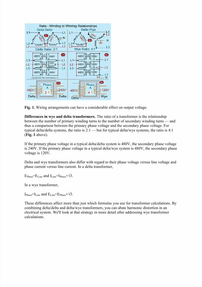
Fig. 1. Wiring arrangements can have a considerable effect on output voltage.
Differences in wye and delta transformers. The ratio of a transformer is the relationshipbetween the number of primary winding turns to the number of secondary winding turns ² andthus a comparison between the primary phase voltage and the secondary phase voltage. For typical delta/delta systems, the ratio is 2:1 ² but for typical delta/wye systems, the ratio is 4:1(Fig. 1 above).
If the primary phase voltage in a typical delta/delta system is 480V, the secondary phase voltageis 240V. If the primary phase voltage in a typical delta/wye system is 480V, the secondary phasevoltage is 120V.
Delta and wye transformers also differ with regard to their phase voltage versus line voltage andphase current versus line current. In a delta transformer,
EPhase=ELine and ILine=IPhase×¥3.
In a wye transformer,
IPhase=ILine and ELine=EPhase×¥3.
These differences affect more than just which formulas you use for transformer calculations. Bycombining delta/delta and delta/wye transformers, you can abate harmonic distortion in anelectrical system.We'll look at that strategy in more detail after addressing wye transformer calculations.

8/7/2019 alculating Motor Speed
http://slidepdf.com/reader/full/alculating-motor-speed 7/10
Fig. 2. As this example shows, the line and phase currents are equal in a wye transformer.
Wye current and voltage calculations. In a wye transformer, the 3-phase and single-phase120V line current equals the phase current (IPhase = ILine) (Fig. 2 on page C20).
Let's apply this to an actual problem.What's the secondary phase current for a 150kVA, 480V to208Y/120V, 3-phase transformer (Fig. 3 on page C20)? ILine=150,000VA÷(208V×1.732)=416A,or IPhase=50,000VA÷120=416A
To find wye 3-phase line and phase voltages, use the following formulas:
EPhase=ELine÷¥3ELine=EPhase×¥3
Since each line conductor from a wye transformer is connected to a different transformer winding (phase), the effects of 3-phase loading on the line are the same as on the phase (Fig. 4
on page C21). A 36kVA, 208V, 3-phase load has the following effect:
Line power=36kVAILine=VALine÷(ELine×¥3)ILine=36,000VA÷(208V×¥3)=100APhase power=12kVA (any winding)IPhase=VAPhase÷EPhase IPhase=12,000VA÷120V=100A
Wye transformer balancing and sizing. Before you can properly size a delta/wye transformer,you must make sure that the secondary transformer phases (windings) or the line conductors are
balanced. Note that balancing the panel (line conductors) is identical to balancing the transformer for wye transformers. Once you balance the wye transformer, you can size it according to theload on each phase. The following steps will help you balance the transformer:
8/7/2019 alculating Motor Speed
http://slidepdf.com/reader/full/alculating-motor-speed 8/10
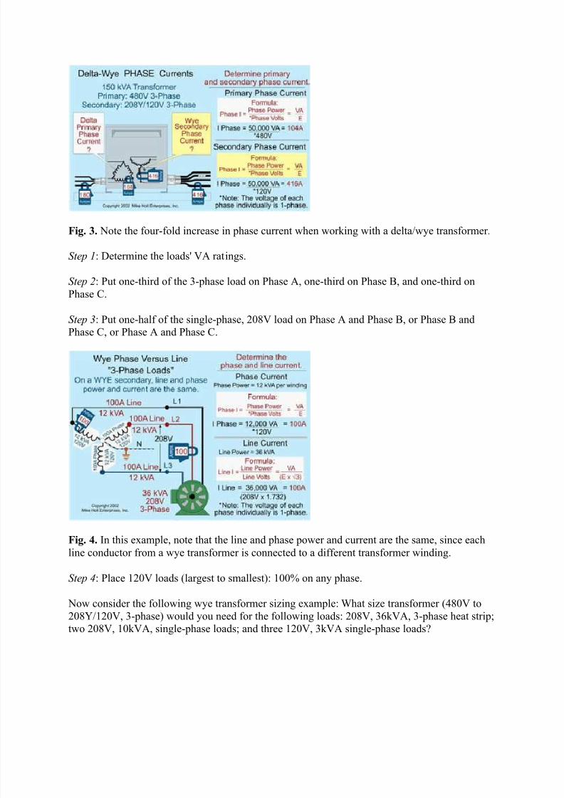
Fig. 3. Note the four-fold increase in phase current when working with a delta/wye transformer.
Step 1: Determine the loads' VA ratings.
Step 2: Put one-third of the 3-phase load on Phase A, one-third on Phase B, and one-third onPhase C.
Step 3: Put one-half of the single-phase, 208V load on Phase A and Phase B, or Phase B andPhase C, or Phase A and Phase C.
Fig. 4. In this example, note that the line and phase power and current are the same, since eachline conductor from a wye transformer is connected to a different transformer winding.
Step 4: Place 120V loads (largest to smallest): 100% on any phase.
Now consider the following wye transformer sizing example:What size transformer (480V to208Y/120V, 3-phase) would you need for the following loads: 208V, 36kVA, 3-phase heat strip;two 208V, 10kVA, single-phase loads; and three 120V, 3kVA single-phase loads?

8/7/2019 alculating Motor Speed
http://slidepdf.com/reader/full/alculating-motor-speed 9/10
a) three single-phase, 25kVA transformersb) one 3-phase, 75kVA transformer c) a or bd) none of these
Phase A=23kVAPhase B=22kVAPhase C=20kVA
The Table sums up the kVA for each phase of each load. Note that the phase totals (23kVA,22kVA, and 20kVA) should add up to the line total (65kVA). Always use a ³checksum´ like thisto ensure you have accounted for all items and the math is right.
If you're dealing with high-harmonic loads, the maximum unbalanced load can be higher than thenameplate kVA would indicate. Matching the transformer to the anticipated load then requires ahigh degree of accuracy if you want to get a reasonable level of either efficiency or power
quality.One approach to such a situation is to supply high-harmonic loads from their own delta/deltatransformer. Another is to supply them from their own delta/wye and double the neutral. Theapproach you choose will depend on the characteristics of your loads and how well you lay outyour power distribution system.
For example, you might put your computer loads (which have switching power supplies) on adelta/delta transformer, which you would feed from a delta/wye transformer. This would greatlyreduce the presence of harmonics in the primary system, partly due to the absence of a neutralconnection. But the behavior of the delta/delta transformer itself, combined with the interaction
of delta/delta and delta/wye, will also cause a reduction in harmonics. Notice the word ³might´in the question of whether to implement this kind of design. Grounding considerations can makeit an undesirable approach, depending on the various loads and the design of the overall electricalsystem. Keep in mind that this is one of the many ways to mix and match transformers to solvepower quality problems.
Due to uptime or power quality concerns with complex loads, you may need to mix and matchtransformer configurations as in the previous example. And that's something you can't do unlessyou understand both delta and wye calculations.
Another issue is proper transformer loading. As a rule of thumb, 80% loading is a good target. If you overload the transformer, though, it goes into core saturation and output consists of distortedwaveforms. The clipped peaks typical of saturated transformers cause excess heating in theloads. This issue of transformer loading means you're going to have to perform the transformer calculations just to get basic power quality and reasonable efficiency.
So it's important not to oversimplify your approach to transformer selection. It's usually best todo all the calculations using the nameplate kVA. Then, design the distribution system as thoughall loads are linear.When that's done, identify which loads are high harmonic, such as electronic

8/7/2019 alculating Motor Speed
http://slidepdf.com/reader/full/alculating-motor-speed 10/10
ballasts, computer power supplies, and motors with varying loads. At this point, you canefficiently work with a transformer supplier to develop a good solution.
Now that you understand delta and wye transformer calculations, you can see how importantthey are to being able to do a quality installation any time you're specifying transformers or
considering adding loads to existing transformers. This ability is also important if you're trying tosolve a power quality problem or a problem with ³unexplained´ system trips. You may wish tosharpen this ability by purchasing an electrical calculations workbook or taking on this kind of work in your electrical projects.
Advantages and Disadvantages of Electric Traction
y View
y Edit
Advantages include:
* Lower running cost of locomotives and multiple units* Higher power-to-weight ratio, resulting in
o Fewer locomotiveso Faster accelerationo Higher practical limit of power o Higher limit of speed
* Less noise pollution (quieter operation)* Lower power loss at higher altitudes* Lack of dependence on crude oil as fuel
Disadvantages include:
* Significant cost of electrification* Increased maintenance cost of the lines* Overhead wires further limit the clearance in tunnels


![·AC Input BLDC Motor Speed Control System ·Wide Speed ...Speed range of Ezi-SPEED: 50~4,000 [rpm] Speed range of Inverter + AC induction motor: 200~2,400 [rpm] (Speed Ratio: 1:80)](https://img.pdfslide.net/doc/110x75/5f05a68b7e708231d41404c9/ac-input-bldc-motor-speed-control-system-wide-speed-speed-range-of-ezi-speed.jpg)


![Digital Speed Control of DC Motor for Industrial ...eprints.covenantuniversity.edu.ng/8667/1/WCE2017_pp371-375.pdf · motor speed control [11]. These devices control the motor speed](https://img.pdfslide.net/doc/110x75/5e69a6e5b6b4f7034015a3e3/digital-speed-control-of-dc-motor-for-industrial-motor-speed-control-11-these.jpg)