Embed Size (px)
DESCRIPTION
alfa laval, aldec g2-95 decanter operating manual
Citation preview

Rev. 1; 8/2011
TYPICAL ALDEC G2-95 Decanter & Controls Operation and Maintenance Manual
TABLE OF CONTENTS
VOLUME I SECTION 1 TAB NO. General Information
Purpose of this Manual ............................................................................ 1 Safety Precautions for Alfa Laval Centrifuges ......................................... 2 Important Customer Service Information ................................................. 3 Warranty .................................................................................................. 4 Storage Requirements ............................................................................. 5 Glossary and Abbreviations ..................................................................... 6 SECTION 2
Decanter Information
Installation Data ....................................................................................... 1 Operator’s Manual ................................................................................... 2 Spare Parts Catalogue ............................................................................ 3 SECTION 3
Mechanical Drawings
Centrifuge Dimensional Dwg. 61242879 ................................................. 1 Installation Guide Dwg. 61241412 ........................................................... 2 Materials of Construction Dwg. 61241413 ............................................... 3 Centrifuge Supplied Flexible Connections, Dwg. No. 75701 ................... 4 Centrifuge Accessory Cut Sheets ............................................................ 5 I Rev. 1

Rev. 1; 8/2011
SECTION 4 TAB NO. Supplied Tools and Spares
Supplied Tools ......................................................................................... 1 Supplied Spares ...................................................................................... 2 Supplied Plate Dams ............................................................................... 3 Supplied Bowl Truck ................................................................................ 4 SECTION 5 Supplementary Information
Troubleshooting Guide ............................................................................ 1 Recommended Spare Parts .................................................................... 2 Centrifuge Data Sheets ........................................................................... 3 Equipment Data Summary Forms ........................................................... 4 I Rev. 1 Preventive Maintenance Summary Forms ............................................... 5 I Rev. 1 Startup Documentation & Test Reports ................................................... 6 SECTION 6 Electrical Drawings
Operator Panel Wiring Diagram; Dwg. 8731875...................................... 1 Starter Panel Wiring Diagram; Dwg. 8731876 ......................................... 2 Interconnect Wiring Diagram; Dwg. 8731877 .......................................... 3 Spare Parts Bill of Material; Dwg. 8731878 ............................................. 4 Process & Instrumentation Diagram; Dwg. 8731879 ............................... 5 Main Drive Motor Data ............................................................................. 6 Backdrive Motor Data .............................................................................. 7 SECTION 7 Controls Operating Data
Sequence of Operation ............................................................................ 1 Parameter Sheets .................................................................................... 2 “As-Installed” Main Drive VFD Parameters ..................................... a “As-Installed” Backdrive VFD Parameters ...................................... b “As-Installed” DLM+ Parameters ..................................................... c Decanter Logic Manager; Operator Interface Manual .............................. 3 Variable Frequency Drive (VFD) Manual ................................................. 4 Electrical Documentation CD ................................................................... 5 I Rev. 1
Electrical Documentation; Operator and Starter Panel Cut Sheets CD ... 5 I Rev. 1


_______________________________________________________________________________
Warranty The following warranty applies to the equipment manufactured by Alfa Laval Inc. for the City of Tallahassee, FL, Thomas P. Smith WRF Improvements Project; Alfa Laval Project No. 395293. Alfa Laval warrants to the original Purchaser/Owner that the decanters are free from defects in materials and workmanship for a period of twenty-four (24) months from the date of shipment, or eighteen (18) months from successful startup and acceptance, whichever occurs first. In addition to the above, Alfa Laval warrants to the original Purchaser/Owner defects and wear on the abrasion resistant protection systems as follows;
a) Scroll Conveyor Tiles - 15,000 hours or 3-years (whichever occurs first) b) Cake Discharge Ports – 15,000 hours or 3-years (whichever occurs first) c) Centrifuge Bowl – 25,000 hours or 3-years (whichever occurs first)
The maximum acceptable conveyor tile abrasion loss shall be as called out in the specifications. It is the responsibility of the Owner, to notify Alfa Laval in writing of the alleged defect within the timeframe stipulated above. Alfa Laval reserves the right to review the operating and maintenance records for the equipment to ensure compliance with the Alfa Laval supplied guidelines. This shall be the sole and exclusive remedy available to the Owner. Excluded from the foregoing guarantee are damages caused by ordinary wear and tear, erosion or corrosion; or by misuse, abuse or improper handling by the Purchaser/Owner or any third party. LIMITATION OF LIABILITY Alfa Laval makes no additional warranties, expressed or implied, whether of merchantability or otherwise, other than stated above. Alfa Laval shall in no event be liable for any general, special or consequential damages for loss, damage or expense directly or indirectly arising from Owner’s inability to use the equipment either separately or in combination with any other equipment or from any other cause. Owner agrees that Alfa Laval shall not be liable to Owner for any indirect, special or consequential damages, whether alleged in the contract or in tort. Equipment, parts or accessories manufactured by others carry the guarantee of the manufacturer only. Any warranties or claims which differ from the foregoing are unauthorized by Alfa Laval and become the warranty solely of the party making them, unless specifically authorized in writing by an Officer of Alfa Laval. Should any provisions of the foregoing be held ineffective, the remaining provisions shall continue in full force and effect.
______________________________________________________________________________ ALFA LAVAL INC.
5400 International Trade Drive, Richmond, VA 23231 USA Main: (804) 222-5300 Fax: (804) 236-3276 Rev. 0 05/14/010

Section 1: Storage Area Requirements and Stored Equipment Maintenance
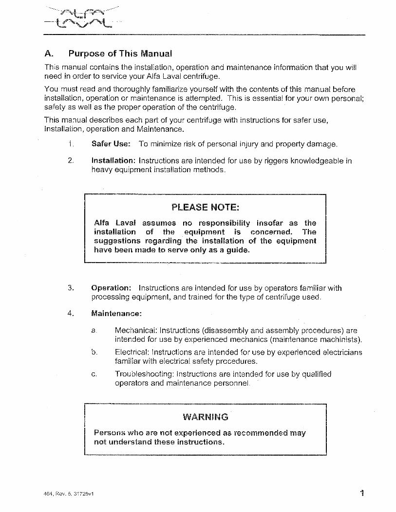
A. General
Storage Environment - Applicable to all equipment
1. Storage of an Alfa Laval Centrifuge System is to be indoors, in a temperature controlled environment, protected from the elements.
2. “Temperature controlled environment” is an area that is thermostatically controlled with adequate air ventilation to prevent stratification and has a temperature range maintained between 50° and 90°F.
3. If a temperature controlled environment is not available, power must be provided to the motor space heaters and control panel space heaters as a minimum protection against accumulation of condensate. If heaters are not provided, then commercial space heaters should be acquired for use during storage.
CONCERNING OUTDOOR STORAGE
Although Alfa Laval centrifuges are capable of outdoor operation, Alfa Laval does not recommend storing centrifuges outdoors. The difference is that the bearing lubricants of operating centrifuges continuously cover and protect the bearings due to circulation and distribution.
If storing outdoors cannot be avoided, then the centrifuge only may be stored outdoors for up to one month. It must be suitably protected from the direct impingement of the elements. All control and drive components must be stored indoors. Outdoor storage of centrifuges in corrosive environments, typical of coastal regions, must be avoided entirely.
4. To prevent bearing fret, the storage area, whether indoors or outdoors, should not be subjected to constant vibration.
5. Openings: Keep all openings leading to the interior of the equipment sealed.
6. Coat unpainted surfaces with a rust inhibitor.
7. Painted Parts:
A. Clean and degrease the parts. B. Touch-up or repaint as necessary.

8. Wrap the entire Centrifuge System to minimize dirt and dust infiltration.
NOTE
Do not paint rotating shafts or threaded parts.
9. Lubrication: At the beginning of the storage period, lubricate all grease lubricated centrifuge bearings and drive motor and backdrive motor bearings in accordance with the lubrication instructions. Thereafter, grease every six months while in storage. On motors, all drains must be fully operable while in storage and/or the drain plugs removed. All breathers and automatic “Tee” drains on motors must be operable to allow breathing at points other than through the bearing fits.
10. Maintenance Log: Maintain a log to record each task performed during storage of equipment.
B. Motors
1. Every six months and just prior to placing in operation, measure the resistance of the motor windings with a megger. Minimum reading is 1 megaohm. If the reading is below this value, drying is necessary. Contact the motor manufacturer for drying procedures.
2. Every Month, rotate the shafts of the motors at least 10 revolutions to keep the bearings lubricated and to prevent them from rusting and brinnelling.
C. Control Consoles
Change corrosion inhibitors once a year.
D. Programmable Controllers
Observe the humidity recommendations and replace batteries as directed in the programmable controller manufacturer’s instructions.
E. Centrifuge
1. Initially, when placed in storage, and monthly thereafter, rotate the bowl by hand at least 20 revolutions. Hold the pinion shaft (the shaft protruding from the gear box) stationary while rotating the bowl.
CAUTION
DO NOT PLACE HANDS NEAR PULLEYS, BELTS, AND OTHER PINCH POINTS WHILE ROTATING BOWL!
NOTE
Ideally, if possible, the centrifuge should be installed and run a minimum of one hour at least once a week. If this is possible, the lubrication interval should be the same as an
operating centrifuge.

Section 2: General Pre-Startup Procedures
This section is applicable to all equipment.
A. If Equipment Has Been Stored More Than One Year
1. Before startup, inspect all seals, gaskets, O-rings, belts and other elastomeric parts to determine their condition, since these parts can become brittle over time.
2. If the equipment has been exposed to low temperature for an extended period of time, unpacking it before it has reached room temperature can cause water condensation on the cold surfaces. This must be avoided, especially with motors, since the presence of moisture can cause electrical failures.
B. If Equipment Has Been Stored More Than Two Years
Replace all bearings, seals, gaskets, O-rings, belts, and other elastomeric parts.
C. Motor
1. Be sure all lubrication passages are clear of hardened lubricant.
2. Purge bearings of grease to their proper operating quantity.
3. If motor has been stored for more than six months, measure the resistance of the motor windings with a megger. If the reading is less than 1 megohm, contact the motor manufacturer for drying procedures.
4. If stored more than three years, the motor should be completely dismantled and inspected by an authorized service facility of the motor manufacturer.
D. Electrical Controls
1. If dirty, vacuum clean. Do not use metal tipped hoses.
2. Check and tighten all terminal connections.
3. Check for moisture and corrosion. Do not operate until all corroded parts have been replaced or repaired.
4. Remove desiccant and corrosion inhibitor.
E. Coated Parts
If parts have been coated with rust preventive materials, remove these materials before startup.
F. Lubrication
Lubricate the equipment before placing in service.

Section 3: Specific Pre-Startup Procedures
A. Centrifuge – After long term storage, Alfa Laval recommends Pre-Startup activities be performed by an Alfa Laval Field Service Representative.
1. Gear Box: If the gear box has been stored for more than one year, completely drain and re-fill with the recommended quantity of specified oil.
2. Main Drive Motor: Purge bearings of grease to proper operating quantity.
3. Backdrive Motor: Purge bearings of grease to proper operating quantity.
4. Bowl Main Bearings: Purge bearings of grease to proper operating quantity.
5. Conveyor Bearings: Purge bearings of grease to proper operating quantity.
6. Check and tension belts as required.
Section 4: Cleaning
A. Vacuum Cleaning
Vacuuming is efficient in removing dust from most equipment, but is especially necessary with electrical controls, and is the only method recommended.
WARNING
Do NOT use compressed air for cleaning!
_______________________________________________________________________________________________________________________
Section 1-6 O & M Instruction Manual
_______________________________________________________________________________________________________________________
1
GLOSSARY BACK DRIVE Used to vary the pinion shaft speed, which varies the conveyor
speed via the gearbox ratio. BOWL ASSEMBLY The main rotating element inside of the centrifuge. It is a stainless
steel cylinder which houses the conveyor. BOWL EXTENSION The conical end of the bowl assembly. This is at the rear end,
where the solids are discharged. The interior surface of the bowl extension is known as the beach.
CONVEYOR BEARINGS Located inside the conveyor and are used to support conveyor
inside bowl assembly. CONVEYOR The conveyor is the helically flighted screw housed inside of the
bowl. It rotates at a speed slightly slower than the bowl speed. The scrolling action conveys settled solids out of the centrifuge.
CENTRATE See EFFLUENT. DAMS The dams are adjustable or interchangeable weirs at the liquids
end of the machine. They raise or lower the pond level in the centrifuge.
DELTA See DIFFERENTIAL RPM. DIFFERENTIAL RPM The difference in speed between the bowl and the conveyor. Also
called “DELTA”, or Delta RPM. EFFLUENT The liquid leaving the centrifuge after it has separated from the
cake. Also called Centrate. FEED The process slurry containing solids and liquid. FEED NOZZLE Port in the feed zone of the conveyor through which the feed is
discharged from the conveyor into the bowl. FEED TUBE The stationary pipe that injects the feed stock into the rotating
assembly. It is located at the rear of the centrifuge.

_______________________________________________________________________________________________________________________
Section 1-6 O & M Instruction Manual
_______________________________________________________________________________________________________________________
2
FEED ZONE The interior section of the conveyor where the feed nozzles and
accelerator are located. The feed stock is accelerated to conveyor speed in the feed zone.
FRAME The main system of support for the rotating assembly. It is the
structural portion of the Frame and Casing assembly. FRONT HUB An element of the bowl assembly, it is the “cap” at the front end.
The gearbox adapter mounts to it and the front pillow block bearing is located on it.
G-FORCE Gravity. The acceleration constant which we use to describe the
force which separates the solids from the liquids. GEARBOX A two stage planetary transmission that controls the rotational
speed of the conveyor. GEARBOX ADAPTOR Mounted on the front hub, this is the connecting interface between
the bowl and the gearbox. LUBE OIL SYSTEM The component mounted near the centrifuge that filters, cools, and
pumps lubricating oil to the main pillow block bearings. MAIN DRIVE ASSEMBLY The drive motor, base, and belts that provide the rotational energy
for the rotating assembly. O-RINGS Elastomers with circular cross sections used to seal metal to metal
surfaces. OIL FLOW INDICATORS Monitors flow of oil to the main pillow block bearings and will shut
down the machine if flow is insufficient. PILLOW BLOCK Two spherical contact roller bearings located at the front and the BEARING rear of the bowl. They support the rotating assembly. PINION SHAFT Input shaft of the gearbox. POLYMER/POLY A polyelectrolyte chemical added in small amounts to improve
settling of solids in liquids.

_______________________________________________________________________________________________________________________
Section 1-6 O & M Instruction Manual
_______________________________________________________________________________________________________________________
3
POND LEVEL The actual depth of liquid inside the bowl as measured from the
inner diameter of the bowl to the surface of the liquid “cylinder“ formed inside the rotating bowl. This depth of liquid is defined by the physical measurement of the dams that are installed in the front end of the machine.
REAR HUB An element of the bowl assembly. It is the “cap” located at the
rear. The pulley mounts to it and the rear pillow block bearing is located on it.
RETURN OIL TEMP. Monitor the temperature of the oil returning from the main pillow SWITCHES block bearings and will shut the machine down if the temperature
exceeds the set point. ROTATING ASSEMBLY The group of centrifuge parts that rotate within the frame and
casing assembly. The rotating assembly is composed of the bowl assembly, conveyor assembly, pillow block bearing housings, and gearbox adapter.
SEALS Used to retain grease inside bearing cavities. THICKENING Liquid/Solids separation. Y-STRAINERS Metal screens housed in pipe threaded fittings used to filter oil
before introduction to the main pillow block bearings.

_______________________________________________________________________________________________________________________
Section 1-6 O & M Instruction Manual
_______________________________________________________________________________________________________________________
4
ABBREVIATIONS ABC2 Advanced Backdrive Controller, Series 2 AC Alternating Current A-O-M Auto /Off/Manual Aux Auxiliary BD Backdrive CIP Clean-in-Place DC Direct Current DCS Distributive Control System E-Stop Emergency Stop GFCI Ground Fault Circuit Interrupter GPM Gallons (US) per Minute HTMAS High Tensile Micro Alloy Steel I / O Input / Output JB Junction Box LED Light Emitting Diode LPM Liters per Minute MCC Motor Control Center MCP Main Control Panel OIU Operator Interface Unit PB Pushbutton PLC Programmable Logic Controller RPM Revolutions per Minute RTD Resistance Temperature Detector SD Shutdown SS Selector Switch TB Terminal Block V Volt VFD Variable Frequency Drive W Warning W-D Wye - Delta

h
ID English EN
INSTALLATIONDATA
Decanter Centrifuge
Alfa LavalAlfa Laval
FRONT


Alfa Laval Rev. 2007-08 ID
Chapter Contents
0.00.0
0 About This Manual
1 Safety Instructions
2 General Information
3 Space Requirements
4 Foundation
5 Connections and Venting
6 Electrical Installation
7 Supplementary DocumentationThe material inserted in section “Supplementary Documenta-tion” consists mainly of technical documentation specific tothe actual delivery of the decanter, i.e. installation dimensions,electrical wiring diagrams, extra control equipment, etc.
InstalenTOC.fm i


Alfa Laval Rev. 2007-08 ID
0.0INSTALLATION DATA
ABOUT THIS MANUAL
This Installation Guide (volume ID) forms part of a set of man-uals including Operators Manual (volume OM) and SpareParts Catalogue (volume SP). The three volumes contain thenecessary information for installing, running and servicingthe Alfa Laval decanter centrifuges.
This manual contains information and sketches necessary forplanning the installation of site and for the actual installationprocedure.
0
WARNING Never allow persons who have not read and understood the safety in-structions in this manual to operate or service the decanter. The material inserted in section 'Supplementary Documenta-tion' consists mainly of technical documentation specific to theactual delivery of the decanter, i.e. installation dimensions,electrical wiring diagrams, extra control equipment, etc.
0.0-1INSTALDA.EN0.EN0


Alfa Laval Rev. 2005-05 ID
1.01 Safety Instructions1.0
The Decanter
1. The decanter delivered must not be used to separate flam-mable, toxic, corrosive, or radioactive process mediawithout prior written approval from Alfa Laval.
2. Read this manual and the Operator's Manual before at-tempting to install or operate the decanter equipment,and follow all recommendations.
3. Do not operate the decanter with damaged or missingwarning labels.
4. Do not operate the decanter if the vibration level exceeds24 mm/sec (RMS) (US: 1 inch/sec).
5. Do not operate the decanter with feed temperatures ex-ceeding the limits stated on the DATA SHEET included inall three volumes of the Instruction Manual.
6. Never attempt to start the decanter with frozen water orfrozen or hardened process material in the bowl.
7. Do not exceed the maximum bowl speed or solids densityspecified on the decanter name-plate and DATA SHEET.
8. Do not operate the decanter without belt guards and otherguards provided.
9. Periodically check all the automatic shut-off devices andmonitoring systems for correct operation.
contd...
FAILURE TO FOLLOW THESE RULES MAYRESULT IN SEVERE PERSONAL INJURY ORPROPERTY DAMAGE.
1.0-1INSTALDA.EN1.EN1

Alfa Laval Rev. 2005-05 ID
10. Do not attempt dismantling until the decanter has cometo a complete stop, the main power is shut off, and the dis-connected main switch is locked with a safety lock.
11. Do not operate the decanter if the bowl, motor, or sup-porting structure show cracks, pitting, holes, or grooves.
12. Do not use tools other than those recommended by AlfaLaval to dismantle and assemble the decanter.
13. Do not attempt to use the decanter for any application orprocess material other than that stated on the original pur-chase documentation without first consulting Alfa Laval.
14. Follow all lubricating procedures and schedules.
15. Check periodically - at least once a year - for loose bolts onfoundation and supporting structures, covers, hatchesand pipe connections of decanter and motor.
16. Do not get rags or loose clothing near rotating parts.
17. At all times follow the recommended sequence and proce-dures for dismantling, assembly, operation, and mainte-nance. Do not introduce new procedures without firstconsulting Alfa Laval.
18. Only allow trained personnel to operate, clean, dismantleor assemble the decanter.
19. Do not operate the decanter before the installation is com-plete.
20. Do not operate the decanter with any electrical motor run-ning in the opposite direction to that indicated by the ar-rows on the frame or otherwise specified.
contd...
1.0-2 INSTALDA.EN1.EN1

Alfa Laval Rev. 2005-05 ID
21. If the decanter is fitted with a frequency inverter, makesure that the maximum possible frequency will not causeoverspeeding of the decanter. At least two separate pro-tections against overspeed must be provided. See section6.9.
22. Do not turn on feed or water before the decanter has at-tained its full speed.
23. If the decanter is operated with hot, corrosive, or aggres-sive liquids, care should be taken that any incidental spill-age from the decanter cannot hit persons below the centreline of the decanter.
24. Never turn on feed or large amounts of hot, corrosive, oraggressive liquids when the decanter is at a standstill, asthese liquids might hit persons below the centre line of thedecanter.
25. Never start the feed pump or flush the decanter beforeopening the discharge valves or starting the dischargepumps, including any conveying means for the liquid andsolids phases.
26. When personnel are working on a decanter with a hingedcover, care should be taken that the cover is not closed un-intentionally by other persons or by moving machinery,which might cause injury.
27. Do not touch the solids phase discharging from the de-canter as hard lumps being ejected with high speed mightcause injury.
28. When using straps to lift the complete decanter or any ofits parts such as the rotating assembly, make sure to pre-vent the part hanging by the straps from sliding.
29. When lifting the decanter, use the slings specified on thedimensioned drawing.
30. The lifting eyes in the bearing housings, if fitted, must notbe used for lifting the bowl assembly.
contd...
1.0-3INSTALDA.EN1.EN1

Alfa Laval Rev. 2005-05 ID
Electrical Installation1. Install and earth all equipment in accordance with re-quirements of the Local Electricity Authority.
2. Use an “on-load” isolator or circuit breaker (a main switchfor switching off during run-up) on the main power sup-ply.
3. Check that the voltage and the frequency are in agreementwith labels on motors and other electrical equipment.
4. De-energize all equipment before connecting and discon-necting test equipment.
Repairs
1. Major repairs to decanter must not be made without firstconsulting with Alfa Laval.
In no circumstances should weld repairs, heating witha naked flame, or other alterations be made to bowl shells,bowl hubs, gearbox adapter, shafts, or other rotating partswithout prior written approval and instructions fromAlfa Laval. Failure to obtain this approval may result infailure of parts involved with possible serious damage toequipment, property, or personnel.
2. Do not operate the decanter on completion of the repairsuntil the belt and/or other guards are re-fitted.
contd...
1.0-4 INSTALDA.EN1.EN1

Alfa Laval Rev. 2005-05 ID
3. Do not exceed the maximum load carrying capacity of thelifting tools. Only use the lifting tools for the intendedpurpose.
4. Replace worn or damaged parts with only originalAlfa Laval parts.
Alfa Laval cannot be held responsible for any damageto property or for injury to persons if genuine parts arenot used.
5. Do not interchange bowl parts, since specific parts are bal-anced as a unit.
The Motor
1. Do not operate a decanter equipped with flame proof mo-tor(s) and control unit(s) until all enclosures have been as-sembled in accordance with the appropriate standards.
2. If a motor should become inoperative, immediately shutoff the power.
3. Always follow motor manufacturer's specifications onbearing lubrication.
4. Do not attempt to operate a motor that is overheated dueto frequent starts and stops. Allow motors to cool to am-bient temperature (as designated on the motor name-plate) before each restart.
Do not attempt to start motor unless the rotating elementsturn freely.
contd...
1.0-5INSTALDA.EN1.EN1

Alfa Laval Rev. 2005-05 ID
Corrosion, Erosion and Pitting of DecanterEquipment It should be recognized that equipment sub-jected to severe erosive or corrosive environments may deteri-orate over a period of time, depending upon the severity of ex-posure and/or possible misuse. Users of high speed centrifu-gal equipment should be aware of this fact and also that ex-tremely high forces are brought into play when their equip-ment is in operation. Any weakening of highly stressed mem-bers by misuse, erosion, corrosion, chemical pitting, or stresscracking must be guarded against.The following points should be noted and the recom-mended action taken:
1. Inspect the outside of the bowl for erosion and corrosion,at least every two months.
2. Do not operate equipment when:
2.1 Holes are worn through rotating parts.2.2 Grooves greater than 2 mm (0.08 inch) deep are worn
in rotating parts.2.3 Evidence of cracks is present in rotating parts.2.4 Chemical pitting of 2 mm (0.08 inch) depth or greater
is present on rotating parts.
3. Chemical Pitting Observed:
All cases of chemical pitting, even under 2 mm depth,should be monitored carefully. This action is almost al-ways due to the breakdown of the passive film on stain-less bowl shell walls, in the presence of chlorides. This of-ten occurs under deposits that have not been cleaned fromthe outside of the bowl wall. High temperature and highacidity accelerate the action.
4. Pay special attention to the bolts assembling the bowl sec-tions. If the process liquid or cleaning agents contain chlo-rides, check these bolts at least once a year and exchangethem at least every three years. Contact Alfa Laval, if indoubt.
Contact Alfa Laval regarding the repair or replacement of pit-ted bowl shells or other parts.
1.0-6 INSTALDA.EN1.EN1

Alfa Laval Rev. 2000-04 ID
2 - General Information2.1 See the last pages ”Supplementary Documentation” for
precise data of the actual delivery of decanter.
2.2 Follow the recommendations below in order to facilitatedaily operations and to create an effective and secure en-vironment for service and repair personnel.
2.3 The decanter and its electric equipment must be protect-ed against rain and snow, and temperatures below 0°C(32°F). If it is not possible to avoid exposing the equip-ment to temperatures below 0°C, make sure that the heatexchanger (if fitted) in the hydraulic back drive system isdrained of water whenever not in use. Standard ABBmotor complies with DIN/ISO IP 55 (ECB Brake IP 54).All other electrical equipment complies with an equal orhigher protection class.
2.4 Place warning lamps and acoustic alarms in such a waythat they can be seen or heard everywhere in the processarea.
2.5 Place control panels and valves in a way that makes iteasy for the operator to reach them.
2.6 Place control panels in a way that they are not damagedmechanically or sprayed by water or product duringtransportation, repair, maintenance, or operation.
2.0-1INSTALDA.EN2.EN2


Alfa Laval Rev. 2000-04 ID
3 - Space Requirements3.1 The passageways must be of adequate width to allow the
passage of necessary transport equipment (fork lifts etc.).
3.2 Lifting gear to remove the bowl from the frame musthave adequate lifting height and capacity (see Dimen-sional Drawing).
3.3 Adequate space must be allowed to accommodate com-plete removal of the feed tube (see Dimensional Draw-ing).
3.4 Allow adequate floor space around the decanter forwork benches, tools, dismantled and new parts, andtransport trolleys.
3.0-1INSTALDA.EN3.EN3


Alfa Laval Rev. 2000-04 ID
04 - Foundation4.1 The decanter must be fastened securely to the floor orany base frame or steel structure.
The maximum static and dynamic foundation loadsfrom the decanter are stated on the dimensioned draw-ing.
The maximum dynamic foundation loads are speci-fied due to the liquid-induced vibrations which may oc-cur at speeds, depending on decanter size, between 200and 1500 rpm during run-down and start-up with a liq-uid-filled bowl.
All static and dynamic loads are distributed equallyon each leg unless otherwise specified on the dimen-sioned drawing.
4.2 If the decanter is mounted on a steel frame it must be suf-ficiently stiff to be free from any resonance within therange from standstill to full speed of the decanter. The maximum permissible vertical and horizontal de-flection of the frame caused by a load in each direction ofthe same magnitude as the maximum static load is
0.5 mm for decanters with bowl size below 430 mm
1 mm for decanters with bowl size above 430 mm
4.3 Maximum permissible vertical misalignment of the vi-bration dampers:
2 mm for decanters with bowl diameter less than430 mm.
4 mm for decanters with bowl diameter greater than430 mm.
4.4 If a decanter and other machinery are placed in the samearea, do not place the machinery in such a way that vi-brations or dynamic forces can be transmitted to the de-canter.
4.0-1INSTALDA.EN4


Alfa Laval Rev. 2006-06 ID
5 - Connections and Venting
5.0 The feed pipe must always be pushed home in the de-canter.
5.1 For plants comprising more than one decanter, each de-canter must have its own feed line with its own feedpump(s).
5.2 As the outlets for solids and liquid are placed under thedecanter, enough space must be provided for collection ofsolids and liquid, and for transport equipment for their re-moval.
5.3 The installation must be made in such a way that the ro-tating bowl or any scraping device cannot be reachedfrom underneath the decanter.
5.0-1INSTALDA.EN5

Alfa Laval Rev. 2006-06 ID
5.4 The free flow from the liquid discharge must not be ob-structed. For this reason:
• always dimension the liquid discharge duct accord-ing to the flow rate. The liquid discharge duct mustnot be the limiting factor for the hydraulic capacity.
• avoid too sharp or too many bends.
• always arrange for a slope in the liquid dischargeduct.
5.0-2 INSTALDA.EN5
Alfa Laval Rev. 2006-06 ID
5.5 The liquid and solids discharge ducts or connectionsshould be arranged in short easily assembled and disas-sembled sections to facilitate maintenance and replace-ments.
5.6 Material for connections and fittings should be chosenwith respect to the process.
Special attention must be paid to corrosion, tempera-ture, and safety.
5.7 The connection between the external piping and the feedtube must be flexible. If the decanter blocks, the pressurein the system will increase to full pump pressure, there-fore high quality industrial hose compensator and fittingssuited for the actual pressures must be used.
Take care not to bend or stress plastic connections.
5.8 All connections for feed tube, solids, and liquid discharg-es must be flexible. They must be able to compensate forvibration amplitudes of +/- 5 mm in any direction.
contd...
5.0-3INSTALDA.EN5

Alfa Laval Rev. 2006-06 ID
5.9 The Dimensional Drawing (see supplementary section ofthis book) gives the dimensions for pipe and flange con-nections. The flexible connections should preferably befitted directly to the flanges shown in the dimensionaldrawing.
For the solids and liquid outlets under the decanterthe maximum permissible distance from the flange to theflexible connection is 600 mm and the maximum permis-sible weight of any adaptor is 30 kg.
The weight of any connection fitted between the endof the feed tube and the flexible connection must not ex-ceed 5 kg, and the maximum permissible distance be-tween the feed tube connection and the flexibleconnection is 200 mm.
5.10 Over-pressure in the casing may cause main bearing fail-ures because liquid, steam, solids, dirt, etc. will pass thesealing between casing and bearings.
If both solids and liquid discharge are closed, a suc-tion fan must create the under-pressure in the casing. Thesuction fan should preferably be placed in the neutralcompartment of the casing closest to the liquid end (seepage 5.0-5, figure A).
Optionally, chimneys in the ducting system fromboth liquid discharge and solids discharge can be fitted(see page 5.0-5, figure D).
Alternatively, one shared chimney for both liquidand solids can be used (see page 5.0-5, figure C). Finally,the suction fan can be placed in the chimney(s) (see page5.0-5, figure B).
5.0-4 INSTALDA.EN5

Alfa Laval Rev. 2006-06 ID
5.0-5INSTALDA.EN5

Alfa Laval Rev. 2006-06 ID
5.11 Ensure that large amounts of water vapour from tanks po-sitioned below the decanter will not pass through the liq-uid and solids discharge lines during long periods ofstandstill as the bearings might be damaged.
5.12For Decanters with Paring DiscA blockage of the liquid discharge opening may result ina very high pressure.
For that reason, the downstream pipings and valveson the centrate side should always be open for flow. If itseems probable that this is not the case (logical, electricalor operator's fault) a safety valve which must be set atmax 5 bar should be connected to the liquid dischargeopening.
5.13 Paring disc decanters have a ventilation opening placedbeside the liquid outlet. This opening must not be blockedor restricted.
5.0-6 INSTALDA.EN5

Alfa Laval Rev. 2000-04 ID
6 - Electrical Installation 6.0
6.1 Alfa Laval cannot be held responsible for any damage orinjury caused by faults in installation, design or manu-facturing of electrical equipment not supplied by AlfaLaval.
6.2 The electrical connections and the cable size must be inconformity with Local Electricity Authority regulations.
6.3 For decanters supplied with an electrical panel fromAlfa Laval the diagram is shipped within the panel.
Always study the diagram carefully before startinginstallation work. Ask your Alfa Laval representative ifin doubt.
6.4 The cables on the decanter are normally wired to a junc-tion box. A drawing of the connections to this box is en-closed in the rear of this manual.
6.5 The safety functions must be checked before the firststart.
6.6 Contactors and Cables for Star-Delta ConnectedMotors:When a star-delta starter is used to start the decanter,contactors and cables must be dimensioned to withstandthe load during the starting period.
ATTENTION The starting time in star connection is 2.5 to 4 minutes de-pending upon motor size and the decanter speed. Dur-ing this period of time the amperage is approx. 2.3 times thefull load amperage of the motor.
Example: The full load amperage of a 3 X 380V, 37 kWmotor is 75. During start-up the amperageincreases to 170.Consequently contactors and cables mustbe dimensioned to carry 170 Amp.
contd...
6.0-1INSTALDA.EN6

Alfa Laval Rev. 2000-04 ID
6.7 Contactors and Cables for Motors with Hydrau-lic or Frictional Start Coupling:When a start coupling is used to start the decanter, con-tactors and cables must be dimensioned to withstand theload during the starting period.
ATTENTION In most installations the motor is accelerated in the starmode for maximum 5 seconds to attain its full speed.During this period the maximum amperage will be 2.3 timesfull load amperage.
The delta mode is used to accelerate the decanter to itsfull speed. The starting time in delta connection is 1 to 1.5minutes depending on motor size and full speed. Duringthis period the maximum amperage will be 3 times the fullload amperage.
6.8 Cables and electrical wires must not be attached to thedecanter by means of stiff connections. Arrange for thecabling and wiring to absorb decanter vibration ampli-tudes of +/-5 mm in any direction.
contd...
6.0-2 INSTALDA.EN6

Alfa Laval Rev. 2000-04 ID
6.9 Control panels must not be placed in rooms where the at-mosphere is corrosive as this might cause serious dam-age to the built-in electronic equipment, such as back-drive controllers, frequency converters, PLCs, amplifi-ers, etc.
This applies especially to control equipment with built-in ventilation. In such cases external supply of clean cool-ing air must be provided. As an alternative the controlequipment could be installed in a separate room.
A control panel must fulfil the following minimum safe-ty requirements:
Obligatory Alarms:
The following alarms are obligatory:
• disengaged cover switch
• conveyor load high (see also 'Other Control PanelRequirements' below)
• tripped thermal protection for main motor
Extra Alarms:
The most common extra alarms are:
• speed too high (main drive controlled by frequencyconverter)
• vibration level high
• high oil temperature in the hydraulic system
• low oil level
• low / high brake speed
• high bearing temperature
contd...
6.0-3INSTALDA.EN6

Alfa Laval Rev. 2000-04 ID
Functions which must be switched off by an activatedalarm, emergency stop, or main switch:Each of the mentioned alarms, the activation of the emer-gency stop, or stop by means of the main switch must en-gage the following actions (if decanter is equipped withthe appropriate items):
• stop main motor
• stop feed pump (incl CIP liquid, water, polymer, etc.)
• stop sun wheel motor or electric motor for hydraulicback drive (timer)
• stop solids scraper
• stop vibrator for solids
• stop solids conveyor
Restarting: On a tripped alarm, an activated emergency stop, or abroken mains supply circuit automatic restarting of thedecanter must not be possible before having eliminatedthe conditions which caused the alarm to trip and resetthe tripped alarm and the emergency stop, and after thisremedy a signal has been given to start the decanteragain.
Other Control Panel Requirements:
It must not be possible to start the feed pump before thedecanter has attained its full speed. This can be achievedby using a timer relay or an interlocking to the main mo-tor star-delta starter.
For decanters fitted with an automatic back drive, twoalarm levels are defined: one which should only stop thefeed pump, and one which stops all as above.
Driving a decanter by means of a frequency converter in-volves the immediate risk of overspeeding the decanter.Consequently, electric control panels for decanters mustcontain at least two mutually independent circuits forthe shut down of the decanter in case of overspeeding.These circuits can be:
• frequency converter frequency
• speed signal from main speed sensor.
6.0-4 INSTALDA.EN6

Alfa Laval Rev. 2000-04 ID
0y7 - Supplementary Documentation
7.0-0INSTALDA.EN7


h
OM English EN
OPERATOR’SMANUAL
OPERATIONSERVICEMAINTENANCE
Decanter Centrifuge
Alfa LavalAlfa Laval
Original instruction
FRONT


Decanter Centrifuge Data Sheet
Decanter Specification, Type ALDEC G2-95 Machine No.: 5024795 Date of issue: 2010-09-15
Specification: 882051002-0
Process liquid: Min. 0°C (32°F) - max. 60°C (140°F)
Max. density of compact wet cake at max. bowl speed: 1.5 kg/dm³ Bowl Maximum main speed: 3250 rpm Bowl length: 2244 mm Bowl diameter: 510 mm Beach angle: 10° Solids discharge type: 360°-type with 8 wear liners Solids discharge radius: 138 mm Solids transportation aids, cylindrical section: Ribs Solids transportation aids, taper section: Ribs Material - hubs: AL 111 2377 (Duplex stainless steel) Material - bowl shell: AL 111 2327 (Lean duplex stainless steel) Attention: If the
product is corrosive; Please see note in the description field on top of this document
Material - bolts: A4-80 (AISI 316) Material - seals: Liquid outlet, type: 6 Liquid outlet, radius: 130 mm (fitted from factory: 139 mm)
Conveyor Material - flights: AL 111 2349 (AISI 316) Material - hub: AL 111 2349 (AISI 316)
Wear Protection Bowl solids discharge: Wear liner in tungsten carbide. 8 pieces Part No.
61233941-03 Bowl feed zone liner: Conveyor flights: Tungsten Carbide Tiles / PTA Conveyor feed zone: Tungsten Carbide wear liners Frame / casing: Wear liner in upper casing
Frame and Casing Material - casing / cover: Stainless steel (AISI 316) Inside surface of casing: Liners of stainless steel at discharge areas - painting in
neutral compartment. Gaskets / seals - casing:

Drives Power supply: 3 x 480V / 60 Hz Gearbox, type: Planetary - 2-stage DD Gearbox, max. torque: DD 12.0 kNm Gearbox, ratio: 1:100.8 Back drive: Variable Frequency Drive 30 Hp NEMA (460V, 60Hz) -
max. diff. speed 17.5 rpm at 12 kNm - diff. speed 29.8 rpm at max. 7.1 kNm (Back drive motor, 460VD, 1800rpm, 60Hz,NEMA 286T, part no. 61195635-50)
Back drive parts: Operating main speed: 3250 rpm (NEMA) Max. diff. speed and torque (at operating speed):
G-force at operating speed: 3011 G Main motor: 75 Hp Baldor 460VD Y/D-VFD (365) foot heating –
part No. 61195625-51 Main motor, protection:
Documents & Drawings Manuals, language: Manuals in English Dimension drawing: 61242878 Diagram, decanter junction box: 61211283
Spare Parts Important: When ordering spare parts, always state:
Machine number and type indicated above Part number and designation Quantity
The decanter centrifuge complies with the essential health and safety requirements of council directives 2006/42/EC Machinery Directive
2006/95/EC Low Voltage Directive
2004/108/EC EMC Directive To meet the requirements, the harmonised standard EN 12547 has been used. The technical file for decanter centrifuge is compiled and retained by Product Centre Decanters, Alfa Laval Copenhagen A/S, Maskinvej 5, DK-2860 Søborg, Denmark. Authorised person: Jan Cederkvist, Mechanical Technology.

DATASHEET
Noise Declaration Noise emission data for the decanter declared in accordance with the re-quirements in EN ISO 4871 and EN12547:
LwAd : Declared A-weighted sound power level from the decanter
LpAd : Declared A-weighted emission sound pressure level in a free field over a re-flecting plane at 1 m distance from the decanter
Uncertainty on declared values : LwAd : KwA=2 dB
LpAd : KpA=4 dB
The noise does not contain significant impulsive or tonal components and the peak C-weighted instantaneous sound pressure level LpCpeak is below 130 dB(C) at all operat-ing speeds.
The emission sound power level is measured according to ISO 9614-2 while operatingthe decanter with water as process medium. The sound pressure level is determinedfrom the measured sound power level according to EN ISO 11203.
The sound pressure level can vary –1dB to 2 dB at different positions around the decanter.
The declared values are based on measurements conducted on typical new decanters.
Note that the sound pressure levels are based on free-field conditions and not guaran-teed values. In a normal indoor installation the sound pressure level will be significant-ly higher than the declared free-field sound pressure level due to the reflection ofsound from walls and surroundings.
In order to minimise the sound pressure level at the decanter it is recommended to in-stall the decanter in a room with low reflection of sound from the walls and alwayskeep the decanter in a properly maintained condition.
Operating Speed
[rpm]
Sound Power LevelLwAd
[B(A) re 1 pW]
Sound Pressure LevelLpAd
[dB(A) re 20 μPa]
3250 10.1 823075 10.1 822900 9.9 80
enNOI5150.fm


Alfa Laval OMChapter Contents Page
0.0 1 Safety Instructions .............................................................. 1.0-1
2 Decanter Operating Principle ...................................... 2.0-1
2.1 Main Drive ...................................................................................... 2.1-1
2.2 Differential Speed Control ...................................................... 2.2-12.2.1 VFD Direct Drive .............................................................................. 2.2-2
EN510001.TOC+ 0.0-1

Alfa Laval OMChapter Contents Page
3 Operation and Routine Maintenance .................... 3.1-1
3.1 Before First Start ........................................................................ 3.1-13.1.1 Noise and Vibrations ........................................................................ 3.1-2
3.2 Start/Stop procedures .............................................................. 3.2-13.2.1 Inspect Bowl ...................................................................................... 3.2-13.2.2 Before Start ......................................................................................... 3.2-1
3.2.2.1 Checkpoints ....................................................................................... 3.2-13.2.2.2 Decanters with Mechanical Seals (Optional Equipment) ........... 3.2-1
3.2.3 Start Decanter .................................................................................... 3.2-23.2.4 Stop Decanter .................................................................................... 3.2-2
3.3 Monitoring Operation ................................................................ 3.3-13.3.1 Overload ............................................................................................. 3.3-1
3.3.1.1 Causes of Overload ........................................................................... 3.3-23.3.1.2 Cleaning an Overloaded Bowl ........................................................ 3.3-2
3.3.2 Vibrations ........................................................................................... 3.3-33.3.2.1 Vibration Switch (Optional Equipment) ....................................... 3.3-3
3.4 Routine Cleaning Procedure ................................................... 3.4-1
3.5 Performance Optimization ...................................................... 3.5-1
3.6 Main Drive ...................................................................................... 3.6-1
3.7 Variable Frequency Drive (VFD) ............................................ 3.7-1
3.8 Lubrication ..................................................................................... 3.8-13.8.1 Lubrication of Main Bearings .......................................................... 3.8-13.8.2 Lubrication of Conveyor Bearings ................................................. 3.8-4
3.8.2.1 “Solid Oil” Conveyor Bearings ....................................................... 3.8-43.8.3 Change of grease type - Compatibility of greases ....................... 3.8-53.8.4 Cleaning out grease exits on decanters .......................................... 3.8-53.8.5 Grease accepted by Alfa Laval for lubrication
of decanter bearings ......................................................................... 3.8-53.8.6 Gearbox .............................................................................................. 3.8-7
3.9 Recommended service intervals .......................................... 3.9-1
0.0-2 EN510001.TOC+

Alfa Laval OMChapter Contents Page
4 Disassembling and Assembling ................................... 4.0-1
4.1 Rotating Assembly ...................................................................... 4.1-14.1.1 Remove Bowl ..................................................................................... 4.1-14.1.2 Install Bowl ........................................................................................ 4.1-54.1.3 Remove Large End Hub ................................................................... 4.1-74.1.4 Install Large End Hub ...................................................................... 4.1-74.1.5 Remove Small End Hub ................................................................... 4.1-94.1.6 Install Small End Hub ...................................................................... 4.1-94.1.7 Remove Gearbox ............................................................................... 4.1-104.1.8 Install Gearbox .................................................................................. 4.1-114.1.9 Fit New Wear Liners ........................................................................ 4.1-12
4.2 Main Bearings ............................................................................... 4.2-14.2.1 Disassemble Main Bearing Large End ........................................... 4.2-14.2.2 Assemble Main Bearing Large End ................................................ 4.2-34.2.3 Disassemble the Main Bearing Small End ..................................... 4.2-74.2.4 Assemble Main Bearing Small End ................................................ 4.2-8
4.3 Conveyor Bearings ...................................................................... 4.3-14.3.1 Disassemble Conveyor Bearing Large End ................................... 4.3-14.3.2 Assemble Conveyor Bearing Large End ........................................ 4.3-34.3.3 Disassemble Conveyor Bearing Small End ................................... 4.3-54.3.4 Assemble Conveyor Bearing Small End ........................................ 4.3-6
4.4 Conveyor ......................................................................................... 4.4-14.4.1 Remove Conveyor from Bowl ......................................................... 4.4-14.4.2 Insert Conveyor into Bowl ............................................................... 4.4-2
4.5 Main Drive ...................................................................................... 4.5-14.5.1 Disassemble Main Drive .................................................................. 4.5-14.5.2 Assemble Main Drive ....................................................................... 4.5-34.5.3 Tighten V-belts, Belt Tension Tables .............................................. 4.5-4
4.6 Variable Frequency Drive (VFD) ............................................ 4.6-14.6.1 Disassemble Variable Frequency Drive ......................................... 4.6-14.6.2 Assemble Variable Frequency Drive .............................................. 4.6-1
5 Supplementary Documentation ................................. 5.0-0
EN510001.TOC+ 0.0-3


Alfa Laval Rev. 2008-01 OM
1.11.11 Safety Instructions1.0
The Decanter
1. The decanter delivered must not be used to separate flam-mable, toxic, corrosive, or radioactive process mediawithout prior written approval from Alfa Laval.
2. Read this manual and the Operator's Manual before at-tempting to install or operate the decanter equipment,and follow all recommendations.
3. Do not operate the decanter with damaged or missingwarning labels.
4. Do not operate the decanter if the vibration level exceeds24 mm/sec (RMS) (US: 1 inch/sec).
5. Do not operate the decanter with feed temperatures ex-ceeding the limits stated on the DATA SHEET included inall three volumes of the Instruction Manual.
6. Never attempt to start the decanter with frozen water orfrozen or hardened process material in the bowl.
7. Do not exceed the maximum bowl speed or solids densityspecified on the decanter name-plate and DATA SHEET.
8. Do not operate the decanter without belt guards and otherguards provided.
9. Periodically check all the automatic shut-off devices andmonitoring systems for correct operation.
FAILURE TO FOLLOW THESE RULES MAYRESULT IN SEVERE PERSONAL INJURY ORPROPERTY DAMAGE.
1.0-1SAFETYIN.EN0

Alfa Laval Rev. 2008-01 OM
10. Do not attempt dismantling until the decanter has come toa complete stop, the main power is shut off, and the dis-connected main switch is locked with a safety lock.
11. Do not operate the decanter if the bowl, motor, or sup-porting structure show cracks, pitting, holes, or grooves.
12. Do not use tools other than those recommended by AlfaLaval to dismantle and assemble the decanter.
13. Do not attempt to use the decanter for any application orprocess material other than that stated on the original pur-chase documentation without first consulting Alfa Laval.
14. Follow all lubricating procedures and schedules.
15. Check periodically - at least once a year - for loose bolts onfoundation and supporting structures, covers, hatchesand pipe connections of decanter and motor.
16. Do not get rags or loose clothing near rotating parts.
17. At all times follow the recommended sequence and proce-dures for dismantling, assembly, operation, and mainte-nance. Do not introduce new procedures without firstconsulting Alfa Laval.
18. Only allow trained personnel to operate, clean, dismantleor assemble the decanter.
19. Do not operate the decanter before the installation is com-plete.
20. Do not operate the decanter with any electrical motor run-ning in the opposite direction to that indicated by the ar-rows on the frame or otherwise specified.
1.0-2 SAFETYIN.EN0

Alfa Laval Rev. 2008-01 OM
21. If the decanter is fitted with a frequency inverter, makesure that the maximum possible frequency will not causeoverspeeding of the decanter. At least two separate pro-tections against overspeed must be provided. See section6.9.
22. Do not turn on feed or water before the decanter has at-tained its full speed.
23. If the decanter is operated with hot, corrosive, or aggres-sive liquids, care should be taken that any incidental spill-age from the decanter cannot hit persons below the centreline of the decanter.
24. Never turn on feed or large amounts of hot, corrosive, oraggressive liquids when the decanter is at a standstill, asthese liquids might hit persons below the centre line of thedecanter.
25. Never start the feed pump or flush the decanter beforeopening the discharge valves or starting the dischargepumps, including any conveying means for the liquid andsolids phases.
26. When personnel are working on a decanter with a hingedcover, care should be taken that the cover is not closed un-intentionally by other persons or by moving machinery,which might cause injury.
27. Do not touch the solids phase discharging from the de-canter as hard lumps being ejected with high speed mightcause injury.
28. When using straps to lift the complete decanter or any ofits parts such as the rotating assembly, make sure to pre-vent the part hanging by the straps from sliding.
29. When lifting the decanter, use the slings specified on thedimensioned drawing.
30. The lifting eyes in the bearing housings, if fitted, must notbe used for lifting the bowl assembly.
of the ID manual.
1.0-3SAFETYIN.EN0

Alfa Laval Rev. 2008-01 OM
Electrical Installation1. Install and earth all equipment in accordance with re-quirements of the Local Electricity Authority.
2. Use an “on-load” isolator or circuit breaker (a main switchfor switching off during run-up) on the main power sup-ply.
3. Check that the voltage and the frequency are in agreementwith labels on motors and other electrical equipment.
4. De-energize all equipment before connecting and discon-necting test equipment.
Repairs
1. Major repairs to decanter must not be made without firstconsulting with Alfa Laval.
In no circumstances should weld repairs, heating witha naked flame, or other alterations be made to bowl shells,bowl hubs, gearbox adapter, shafts, or other rotating partswithout prior written approval and instructions fromAlfa Laval. Failure to obtain this approval may result infailure of parts involved with possible serious damage toequipment, property, or personnel.
2. Do not operate the decanter on completion of the repairsuntil the belt and/or other guards are re-fitted.
1.0-4 SAFETYIN.EN0

Alfa Laval Rev. 2008-01 OM
3. Do not exceed the maximum load carrying capacity of thelifting tools. Only use the lifting tools for the intendedpurpose.
4. Replace worn or damaged parts with only originalAlfa Laval parts.
Alfa Laval cannot be held responsible for any damageto property or for injury to persons if genuine parts arenot used.
5. Do not interchange bowl parts, since specific parts are bal-anced as a unit.
The Motor
1. Do not operate a decanter equipped with flame proof mo-tor(s) and control unit(s) until all enclosures have been as-sembled in accordance with the appropriate standards.
2. If a motor should become inoperative, immediately shutoff the power.
3. Always follow motor manufacturer's specifications onbearing lubrication.
4. Do not attempt to operate a motor that is overheated dueto frequent starts and stops. Allow motors to cool to am-bient temperature (as designated on the motor name-plate) before each restart.
Do not attempt to start motor unless the rotating elementsturn freely.
1.0-5SAFETYIN.EN0

Alfa Laval Rev. 2008-01 OM
Corrosion, Erosion and Pitting of DecanterEquipment It should be recognized that equipment sub-jected to severe erosive or corrosive environments may deteri-orate over a period of time, depending upon the severity of ex-posure and/or possible misuse. Users of high speed centrifu-gal equipment should be aware of this fact and also that ex-tremely high forces are brought into play when their equip-ment is in operation. Any weakening of highly stressed mem-bers by misuse, erosion, corrosion, chemical pitting, or stresscracking must be guarded against.The following points should be noted and the recom-mended action taken:
1. Inspect the outside of the bowl for erosion and corrosion,at least every two months.
2. Do not operate equipment when:
2.1 Holes are worn through rotating parts.2.2 Grooves greater than 2 mm (0.08 inch) deep are worn
in rotating parts.2.3 Evidence of cracks is present in rotating parts.2.4 Chemical pitting of 2 mm (0.08 inch) depth or greater
is present on rotating parts.
3. Chemical Pitting Observed:
All cases of chemical pitting, even under 2 mm depth,should be monitored carefully. This action is almost al-ways due to the breakdown of the passive film on stain-less bowl shell walls, in the presence of chlorides. This of-ten occurs under deposits that have not been cleaned fromthe outside of the bowl wall. High temperature and highacidity accelerate the action.
4. Pay special attention to the bolts assembling the bowl sec-tions. If the process liquid or cleaning agents contain chlo-rides, check these bolts at least once a year and exchangethem at least every three years. Contact Alfa Laval, if indoubt.
Contact Alfa Laval regarding the repair or replacement of pit-ted bowl shells or other parts.
1.0-6 SAFETYIN.EN0

Alfa Laval Rev. 2006-08 OM
2 - Decanter Operating Principle
The feed enters the decanter at the intersection of the conicaland the cylindrical part of the bowl through a central feed pipein the hollow drive shaft. After leaving the feed pipe, the feedsuspension is distributed into the rotating liquid in the bowland smoothly accelerated to the full rotational speed. The cen-trifugal force makes the solids settle at the bowl shell. Thescrew conveyor continuously transports the solids toward theconical end of the bowl and through conical bowl part.
The separation takes place throughout the total length of thecylindrical part of the bowl, and the clarified liquid dischargesat the large end where it flows over the rim of exchangeableand/or adjustable plate dams.
The solids are discharged from the small end by centrifu-gal force through outlet openings.
2.0-1nall2001.en0

Alfa Laval Rev. 2006-08 OM
Decanter with Baffle DiscThe space in the cylindrical and conical parts of the bowl, withthe baffle disc between them, act as two communicating ves-sels. The plate dams can be set to a smaller radius than that ofthe solids discharge (negative beach).
Then the heavy phase (the solids) is pressed under thebaffle disc by the hydrostatic pressure of the light phase (theclarified liquid).
ATTENTION The liquid and the solids are discharged at roughly the same radius,and consequently, during start-up, flushing, and irregularities inprocess, discharge of liquid through the solids discharge ports mayoccur owing to lack of solids in the bowl. This should be taken intoconsideration when the decanter is installed.
Figure 2.0.1
2.0-2 nall2001.en0

Alfa Laval Rev. 2001-05 OM
2.1 Main DriveThe decanter i driven by an electric motor. The motor shaftcarries a drive pulley, and motive power is transmittedthrough V-belts to the bowl pulley to drive the bowl.
2.1-1NALL2101.EN0


Alfa Laval Rev. 2006-01 OM
2.2 Differential Speed ControlThe purpose of the differential speed control system is tomake it possible to control the differential speed betweenbowl and conveyor by controlling the speed of the sunwheelshaft of the gearbox.
This is achieved by using an AC motor with Variable Frequen-cy Drive (VFD) in connection with the special Alfa Laval Di-rect Drive gearbox together with a specially designed controlsystem (VFD Direct Drive).
Two ranges of specialized control systems are available, onebased on the Differential Speed Controller (DSC) and onebased on the more advanced Decanter Core Controller (DCC)which takes care of all basic control functions related to the de-canter.
For further details see specific manuals DCC or DSC.
2.2-1NALL2213.EN0

Alfa Laval Rev. 2006-01 OM
2.2.1 VFD Direct DriveThe VFD direct drive system consists mainly of three compo-nents, the specialized control system (based on the DCC orDSC), a variable frequency converter, and a variable speed ACmotor.
The variable speed motor is connected to the decanter gearboxin-line with a flexible coupling.
Direct control of the motor is achieved by varying the electri-cal output voltage, and frequency from the VFD. The VFD re-ceives its speed command signal from the controller and sendsback a motor load or torque signal. If a motor encoder is used,then the quadrature signal from this is connected to the VFDfor determining motor speeds.
The controller (DCC or DSC) is the master controller of thesystem and calculates the speed command signal based on themeasured differential speed and conveyor torque. To determine the differential speed the controller needs infor-mation about the gearbox ratio and measured speed of themotor/sun wheel shaft, and the speed of the bowl.
The bowl speed and the sunwheel speed is measured by in-ductive speed sensors located on the decanter.
2.2-2 NALL2213.EN0

Alfa Laval Rev. 2006-01 OM
WARNING Care must be taken when setting up operational parameters.Firstly, the direct drive motor must always rotate in the same direc-tion as the bowl.
Secondly, the maximum speed specified for the back drive motormust not be exceeded. For most machine types, this means that thespeed limit must be lower than the maximum bowl speed.
The maximum bowl speed depends on the type of decanter,whereas the actual bowl speed also depends on the process.
Thirdly, it must also be ensured that the maximum load does not ex-ceed the gearbox rating. This will result in damage to the gearboxand the pinion shaft. The maximum gearbox load depends on the sizeand type of gearbox fitted.
contd...
2.2-3NALL2213.EN0


Alfa Laval Rev. 2009-12 OM
3 Operation and Routine Maintenance
3.1 Before First Start
Ensure that the transport safety devices (the yellow wedges) have beenremoved. Check that the bowl rotates freely in both directions.
Read all manuals before starting the decanter. Pay special attention to the safety instructions and the procedures for
electrical and mechanical installation of the decanter.
ATTENTION Because the main bearings are filled with grease from the factory, therunning-in procedure described in section 3.8 must be followed inorder to avoid temperature problems.
3.1-1NALL3101.EN0

Alfa Laval Rev. 2009-12 OM
3.1.1 Noise and VibrationsIn spite of the most accurate balancing a rotating body is always slightlyout of balance. As the bowl and the conveyor are two separately bal-anced units rotating at different speeds, the negligible unbalance ofeach unit will coincide, and a momentary increase of noise and vibra-tion occurs in the machine.
The period of time between the moments when this happens dependson the difference in the speeds of bowl and conveyor. The higher thedifferential speed the shorter the intervals, and vice versa.
Increased unbalance caused by wear and/or accumulation of solidswill increase the amplitude of noise and vibration.
A practical hint: The differential speed of the conveyor can be found bycounting these vibrations for exactly one minute.
3.1-2 NALL3101.EN0
Alfa Laval Rev. 2000-03 OM
3.2 Start/Stop procedures3.2.1 Inspect Bowl
A bowl which has not been cleaned, but left clogged by solidsafter operation must be cleaned before the decanter is restart-ed, because dried solids may cause severe unbalance andeventual generation of an overload condition. See section3.3.1.
3.2.2 Before Start
3.2.2.1 Checkpoints
If the decanter has stopped due to overload, the followingpoints must be checked before the decanter is started:
• Are the upper and lower casings free from solidsdeposits?
• Are the discharges open?
• Is the bowl easily rotated by hand?
• Are all guards correctly placed and properly secured?
3.2.2.2 Decanters with Mechanical Seals(Optional Equipment)
Before starting a decanter with mechanical seals, the gas sup-ply system for the seals must be activated and the flow andpressure of gas to the seals must be checked. If the decanter isto be used for inflammable substances, it must be purged withinert gas and it must be ensured that the oxygen concentrationhas gone down to a safe level before the machine is started.Also during run-down until the decanter has stopped, the gassupply to the seals must be activated. See section 3.10.1 ’Instal-lation, Start-up and Operation of Decanters with Circumfer-ential Seals’.
3.2-1NALL3201.EN0

Alfa Laval Rev. 2000-03 OM
3.2.3 Start DecanterRelease EMERGENCY STOP (in most cases: pull out theEMERGENCY STOP knob - or turn it as indicated by arrows).
Start the decanter motor.
Wait 2-4 minutes for the decanter to attain full speed with starconnected circuit before switching to delta connected circuit.
Start the belt conveyor or other transport means for dis-charged solids.
Open the feed valve (if any).
Start polymer pump (if used).
Start the feed pump.
3.2.4 Stop Decanter
ATTENTION When stopping a decanter with mechanical seals make sure that thesupply of gas continues until the decanter has stopped.
Stop feed and polymer pumps (if used), close feed valve (if fit-ted).
Before stopping, flush out with water of suitable temperature.Flush while the machine is running.
Stopping the decanter before its bowl is sufficientlycleaned may give rise to heavy vibrations both during decant-er rundown and during its successive run-up.
ATTENTION When flushing decanters for fat and oil applications, optimal flushingeffect is achieved by using flushing liquids holding temperatures abovethe melting points of the fats and oils run through the decanter.
Using e.g. cold water might cause solidified lumps of fat/oils to re-main in the decanter, which in their turn would give unbalance duringdecanter rundown and during its successive run-up.
Stop the decanter motor when the bowl is thoroughly flushed.Do not flush the decanter when it is inactive.
Press the CENTRIFUGE STOP button on operator panel.
3.2-2 NALL3201.EN0

Alfa Laval Rev. 2008-03 OM
3.3 Monitoring OperationMake particularly sure that there is no increase in vibration.
Check the surface temperature of the main bearing housingsfrom time to time. A temperature rise may indicate a possiblemalfunction in the bearing.
The decanter can optionally be equipped with temperatureprobes for continuous monitoring of the bearing tempera-tures.
ATTENTION The alarm level for main bearing temperature is 100°C (212°F). Atthis temperature level the bearing must be monitored. Especially ifthe increase of temperature is very steep or appears without any ob-vious reason such as after lubrication of the bearing or increased feedor ambient temperature.
The shut down level is 110° C (230°F). At this temperature the de-canter must shut down immediately. If after a restart the tempera-ture again increases to 110°C (230°F), the bearing must be replaced.
After lubrication the temperature may remain high for some hours.
The decanter can optionally be equipped with automaticgreasing system for the main bearings, see Chapter 5 Supple-mentary Documentation.
3.3.1 Overload
If the centrifuge torque exceeds a certain limit, the control sys-tem will deactivate the feed permissive contact and stop thefeed and polymer pumps.
Under these circumstances the control system can be resetand the feed pump restarted from the control panel.
If the conveyor torque exceeds a higher limit, the main motorwill also be switched off.
Then it is advisable to have the feed replaced by water un-til the bowl speed has reached 300 r p m.
When the bowl has stopped rotating, reset the control sys-tem to operative condition.
3.3-1SOME3302.EN0

Alfa Laval Rev. 2008-03 OM
3.3.1.1 Causes of OverloadThe causes of overload may be:
• Too high throughput.• Too high feed concentration.• The properties of the solids (prestraining or grinding the
process liquid before feeding it into the decanter may benecessary).
• Too low differential speed.• Solids clogging the discharge from the casing. (Main mo-
tor overload.)• Too high bowl speed.
3.3.1.2 Cleaning an Overloaded Bowl
If the decanter has stopped due to too high torque on the con-veyor, and the decanter is unable to scroll itself free during anew start, the causes of overload may be as described above,and the only way to clean the bowl will be to disassemble thebowl according to instructions given in section 4.4.1.
When cleaning the conveyor, be careful to clean all of theflights to avoid unbalance when running the decanter after as-sembly.
ATTENTION It is forbidden to attempt to eliminate the overload on a decanter witha standard gearbox by fixing the sunwheel shaft and rotate the bowl,or on a decanter with DD gearbox to use spanners or the like to rotatethe sunwheel shaft, due to the fact that it can cause damage on eitherthe gearbox, the spline shaft or the large end hub.
3.3-2 SOME3302.EN0

Alfa Laval Rev. 2008-03 OM
3.3.2 VibrationsIf excessive vibrations occur while the bowl rotates, stop themain motor immediately and supply liquid to soften the vi-brations.
3.3.2.1 Vibration Switch (Optional Equipment)
To protect the decanter against damage due to heavy vibra-tion, it can be equipped with a vibration sensor which cuts offthe power supply to the main motor and the feed pump in caseof excessive decanter vibrations.
The control panel (or the motor starter) must be providedwith a terminal for the vibraswitch.
Being erected on vibration dampers, the decanter deflectsgreatly during starting and stopping, but these oscillations areso soft that they will not activate the vibraswitch.
Three types of vibration switches are available:
Vibration Level Monitor
See specific manual VLM for further information.
Vitec Vibration Switch
The standard factory-set levels are ¾ in/sec (19 mm/sec) foralarm level and 1¼ in/sec (31 mm/sec) for decanter shut-down level.
For further details about the vibration switch, see sub-supplier's descriptions included in the decanter supply.
3.3-3SOME3302.EN0

Alfa Laval Rev. 2008-03 OM
Robertshaw Vibration Switch (Fig. 3.3.2.1)ResettingThis vibration switch is reset manually by pressing the resetbutton, see figure 3.3.2.1 below
AdjustingTo adjust this vibration switch to trip at the correct vibrationlevel, proceed as follows:When the decanter is not operating, turn the adjusting screwclockwise until the vibraswitch trips.
Then reset it and find the tripping point again. Repeat thisprocedure a couple of times to ensure that the correct trippingpoint has been found.
Then turn the adjusting screw counterclockwise one timeand a third.
ATTENTION Re-adjustment may be required if the vibraswitch shuts off the powersupply because the building where the decanter equipped with vi-braswitch is operating begins to vibrate heavily.
Figure 3.3.2.1 Resetting the Robertshaw Vibration Switch
Reset Button Adjusting Screw
3.3-4 SOME3302.EN0

Alfa Laval Rev. 2010-08 OM
3.4 Routine Cleaning ProcedureBefore starting a cleaning process, please note that the belowprocedure is not product specific and therefore is only intend-ed as a guide.
Before the decanter is stopped, close the valve to the feed andraise the differential speed, if possible, in order to transportthe last solids remains out of the bowl. Always make sure totake precautions against outflow of fluids to other machineswhich provide further treatment of the solids after the separa-tion process, such as for instance sludge drier or the like. Thiscan be done by redirecting the decanter's slide gates or by-passsystem.
Instructions:
1. Flush the decanter with water until the discharged flush-ing water from the large end looks clean and clear.
ATTENTION On decanters with paring disc the flow must not exceed the capacityof the paring disc.
2. Switch off the main motor, but continue to flush. Shut offthe water before the bowl speed decelerates below 300rpm.
3. Open the upper casing of the bowl and check visually ifboth upper and lower casings are clean. Check also ifthere is still product in the bowl. This is done by lookinginto the bowl through the holes of the large end hub andthe solids discharge.
4. Now check if the flushing had the intended effect on thebowl. This is done by turning the sun wheel shaft by handwithout moving the bowl.
3.4-1SOME3401.EN0

Alfa Laval Rev. 2010-08 OM
5. If item 3 and item 4 are not satisfactory, the decanter mustbe accelerated to operating speed again, and the proce-dure is repeated from item 1. If it is not possible to prop-erly clean the bowl according to the above procedure, thebowl must be disassembled and then cleaned.
After having done the above procedure, the observationsshould be evaluated regarding time intervals of the flushingtime in order to obtain the optimum cleaning.
Note!The optimum flushing time of the decanter very much de-pends on the operating conditions.
• If the vibrations level is higher than normal during start-up, the time interval of the flushing of the bowl must be in-creased.
• If the vibrations are not too high at any time, the flushingis of appropriate length.
3.4-2 SOME3401.EN0

Alfa Laval Rev. 1998-01 OM
3.5 Performance OptimizationThe decanter can be adjusted to suit individual requirementsby varying the following control parameters:
Bowl Speed
By varying the rotational speed of the bowl, the G-force can beadjusted to suit the application. The higher speed, the betterseparation.
Liquid Level
Adjust the liquid level (pond depth) to give the optimal bal-ance between liquid clarity and solids dryness by selecting dif-ferent plate dams.
In general terms, the centrate becomes more clear and thecake more wet when diminishing the liquid radius and viceversa.
Differential Speed (Δn or ΔRPM)
The dryness of the cake can be increased when operating witha lower differential speed, but the centrate will be less clearand vice versa. The torque increases with the lower Δn.
The differential speed can be regulated automatically tocompensate for varying content of solids in the feed.
Feed rate
The lower feed rate, the better separation.
contd...
3.5-1NALL3501.en0


Alfa Laval Rev. 2005-04 OM
3.6 Main DriveATTENTION Store spare V-belts in a dry and cool place.Never roll up the V-belts. Sharp bends will damage them.
Before installing new belts, check the pulleys for wear, using,if necessary, a profile and groove gauge.
When installing new belts, rotate the belt drive a few turns be-fore measuring the belt tension, repeating this procedure untilthe belt tension is correct. For the belt tension values, refer tosection 1.9.
Check the belt tension after 0.5-4 hours of full load opera-tion and then every 4000 hours, referring to section 1.9 for thebelt tension values, and not forgetting to rotate the belt driveevery time before measuring the belt tension.
All types of V-belts used for the main drive should normallybe exchanged every 16000 hours.
N9103601.en0 3.6-1


3.7-1NALL3709.EN0
Alfa Laval Rev. 1997-11 OM3.7 Variable Frequency Drive (VFD)
Refer to section 5 ’Supplementary Documentation’ for thespecific descriptions of the electrical motor and the frequencyinverter and follow the given instructions for service andmaintenance.

Alfa Laval Rev. 2009-12 OM
3.8contd...
Figure 3.8.11. Main Bearing, Large End 2. Main Bearing, Smal End3. Conveyor Bearing, Large End 4. Conveyor Bearing, Small End5. Discharge opening, Large End 6. Discharge Opening, Small End
3.8-0 N5103801.EN0

Alfa Laval Rev. 2009-12 OM
3.8 Lubrication(Fig. 3.8.1 shows where the lubricating nipples are located)
GeneralThe lubricants for the decanter must always be stored in a cool, dry, in-door area, and be protected from sunlight. Lubricant properties are verysensitive to contamination and lubricants must never be stored in opencontainers. It is strongly recommended to use lubrication grease suppliedin 400 g (14 ounce) cartridges. If larger containers are used, it is requiredto be very careful, avoid any contamination and always keep the contain-ers completely closed. Lubricant properties will change during storageand the recommended maximum shelf life from the date of filling of thelubricant container is 2 years for grease and 10 years for oil.
ATTENTION The lubrication kit supplied with decanter contains two grease gunslabelled with grease type, one for the main bearings and one for theconveyor bearings. Be very careful not to mix the grease types whenlubricating the bearings or filling the grease guns. Use of wronggrease in the bearings may result in bearing failure.
The grease gun included in the standard decanter delivery will give1.5 g (0.05 oz) in each stroke. For part number: see list of tools inSpare Parts catalogue.
3.8.1 Lubrication of Main Bearings(Nipples 1 and 2 in Fig. 3.8.1)
The main bearings shall always be lubricated while the decanter is run-ning. The optimal lubrication result is obtained if the decanter is lubricat-ed while running at low speed such as during stopping of the decanter ortowards the end of a low speed CIP cycle. Lubrication at low speed shallbe used whenever possible.
Lubricants used for the decanter bearings:
Main bearings: Alfa Laval part number 61203671-50Conveyor bearings: Alfa Laval part number 61203671-58
The standard lubrication interval and lubricant quantity is:
Lubrication time interval: 300 operating hoursLubricant quantity: 24 g (0.85 oz) - 16 strokes with std. grease gun
Lubricate bearings in both ends with the above, specified quantity.
For further information:See Table 3.8.1.
3.8-1N5103801.EN0

Alfa Laval Rev. 2009-12 OM
For decanters operating under extreme temperature conditions and withbearing temperatures constantly above 70°C (160°F), the time interval be-tween each lubrication shall be shortened to 150 hours.It is possible to use shorter time intervals, but if a shorter time interval isused, the quantity of grease shall always be reduced with the same factoras the time interval.
Example: If the quantity of grease specified for 300 hours is X grams,and the time interval between lubrication is 24 hours therequired grease quantity is:
Note: If the standard lubrication time interval is shortened due to extremetemperature conditions, the shortened interval shall be used in the abovecalculation.
The grease quantity and the specified lubrication interval must never beexceeded. Exceeding the specified quantity will cause over-greasing andrisk of high bearing temperatures. Exceeding the time interval will lead toinsufficient lubrication of the bearings.
Temperature alarm limitsThe bearings can withstand a temperature of 120°C / 274°F. For decanterswhere the bearing temperature is measured with a PT100 sensor directlyon the bearing outer race, the temperature limits are:
Warning limit: 110°C / 256°F
Stop limit: 120°C / 274°F
For bearing temperatures measured on the surface of the bearing hous-ings, the temperature limits shall be reduced with approximately 10°C(18°F).
It is always important to ensure that PT100 sensors are properly fitted andthe tip of the sensor is in good contact with the bearing outer race.
Temperature peaksWhen a bearing is lubricated it is normal that there is a temperature peakjust after lubrication. The temperature peaks are caused by the heat gen-erated, when grease is pushed away from the rolling elements. The tem-perature peaks are not critical, unless the bearing temperature exceeds thetemperature limits or does not start to decrease to a normal level after 2-4
24300--------- X grams
3.8-2 N5103801.EN0

Alfa Laval Rev. 2009-12 OM
hours. If the temperature does not decrease it can be a sign of either bear-ing contamination or hardened grease inside the bearing. Frequent greas-ing with smaller quantities will normally lead to smaller temperaturepeaks and is therefore recommended, if there are problems with high tem-perature peaks.If there is a suspicion that a bearing has hardened or contaminated grease,the recommended procedure is to dismantle and clean the bearing com-pletely or change it. Grease should not be tried to be pushed out by add-ing large amounts of new grease or blowing with compressed air.
First start of a decanter – running inWhen a decanter is received from the factory the bearing is filled withgrease. This is to protect the bearing against contamination and dryingout during transport and storage. It is therefore advised not to the start thedecanter at full speed, but first do a low speed rotation of the decanter. Ifthe decanter is driven with a frequency inverter, this can be obtained byrunning the decanter 15-20 minutes at the speed for low speed CIP or runa low speed CIP cycle without feed or water. If the decanter does not havea frequency inverter, it is advised to do 5 repeated starts where the decant-er is stopped when it has reached a speed of approximately 500 r.p.m.
Automatic lubrication system (Optional)The decanter can be equipped with an automatic lubrication system forthe main bearings. The pumping time and the time interval between lu-brication are controlled with a timer.
*) The pumping time is based on a pump delivering 6 grams per hour ateach outlet at continuous pumping. If the lubrication pump is calibratedto deliver a different amount per hour, the pumping time shall be adjust-ed in a proportional manner in order to obtain the same quantity of greaseas obtained with the above settings.
The timer settings shall be:
Time interval between lubrication: 6 hoursLubricant quantity at each lubrication: 0.5 grams (0.018 ounce)
Pumping time*): 5 minutes
3.8-3N5103801.EN0

Alfa Laval Rev. 2009-12 OM
3.8.2 Lubrication of Conveyor Bearings(Nipples 3 and 4 in Fig. 3.8.1)
At lubrication of conveyor bearings, the decanter must be stopped and themain power must be properly disconnected according to the safety in-structions.
For decanters operating with feed temperatures above 90°C (200°F), thelubrication interval shall be shortened to 500 hours.
If the decanter is cleaned with low speed CIP, it is recommended to lubri-cate the conveyor bearings after the low speed. The quantity of greaseshall be reduced according to the number of operating hours betweeneach low speed CIP.
Example: If the quantity of grease specified for 1000 hours is Xgrams, and the time interval between lubrication is 40 op-erating hours, the required grease quantity is
3.8.2.1 “Solid Oil” Conveyor Bearings (Optional)
The decanter can for some applications be equipped with conveyor bear-ings of the “Solid Oil” type.
The “Solid Oil” bearings are lubricated for life and are, in principle, main-tenance free, but it is recommended to now and then lubricate these bear-ings with a smaller amount of grease to protect the bearings against con-tamination from the outside. Do not use more than 1/4 of the normalgrease quantity in order not to damage the seals.
contd...
The conveyor bearings shall normally be lubricated for each 1000 hours. Note that this will coincide with the mandatory visual inspection of bowl, casing and gearbox.
Lubricant quantity, both ends: 70 g (2.5 oz) - 45 strokes with std. grease gun
Lubricate bearings in both ends with the above, specified quantity.
401000------------ X grams
3.8-4 N5103801.EN0

Alfa Laval Rev. 2009-12 OM
3.8.3 Change of grease type - Compatibility ofgreasesIf the grease used for a bearing is changed, it must be checked that thethickener of new grease is compatible with the old grease. If they are notcompatible, the bearings and lubrication channels must be cleaned andfree of old grease before the grease is changed. For main bearings it isstrongly recommended to clean out even if the grease types are listed ascompatible in order to get the optimum result. For conveyor bearings it isusually enough to purge out the old grease. Lubricating with twice theamount specified for normal lubrication will ensure this.
3.8.4 Cleaning out grease exits on decantersIt is recommended to do a cleaning of the grease exits from the bearinghousings each time the decanter is stopped for conveyor bearing lubrica-tion and inspection. This will ensure that the grease exit is not blockedwith old, hardened grease.
3.8.5 Grease accepted by Alfa Laval for lubricationof decanter bearings
■ Lubricants applied to the decanter when delivered▲ Lubricant applied to conveyor bearings on sanitary decanters when delivered❑ Lubricants accepted by Alfa LavalΔ Lubricants accepted by Alfa Laval for conveyor bearings on sanitary decanters◆ Food grade grease
Brand Part No. / Designation Main bearings Conveyor bearings
Alfa Laval61203671-50 ■
61203671-58 ◆ ■ / ▲
SKF LGHP 2 ■
Chevron FM CSC EP2 ◆ ■ / ▲
Texaco Cygnus CSC EP2 ◆ ■ / ▲
KlüberMicrolube GLY 92 ❑
Isoflex NBU 15 ❑
Shell Cassida EPS 2 ◆ ❑ / Δ
SKF LGHB 2 ❑
Table 3.8.1
3.8-5N5103801.EN0

Alfa Laval Rev. 2009-12 OM
Figure 3.8.2
3.8-6 N5103801.EN0

Alfa Laval Rev. 2009-12 OM
3.8.6 Gearbox (Fig. 3.8.2)Change the oil in the gearbox for each 2000 operating hours.
In the front face of the gearbox there are two plugs (drain plugs) screwedinto two holes.
Drain the oil from the gearbox into a suitable container as follows: Rotate the gearbox until the two drain plugs are set in vertical align-
ment.Remove the upper plug and subsequently the lower plug, and drain
all oil from the gearbox.After draining, flush the gearbox with clean gearbox oil: Insert one of
the removed drain plugs into the lower hole and pour approx. 1 litre ofgearbox oil through the upper hole, using an oil syringe. Insert the secondplug into the upper hole and rotate the gearbox by hand as fast as possibleand drain it again as described above.
Then refill the gearbox with oil of the quality given in the lubricationtable. To check the oil level, rotate the gearbox until its arrow marked"UP" points straight up. The oil surface inside the gearbox should thenlevel with the upper drain hole (see level indication mark in Fig. 3.8.3 be-low).
contd...
Lubricant QuantitiesAlfa Laval 61203671-10
61203671-16
Statoil Mereta 320
3.5 kNm DD : 4.0 Litres (4 1/ 4 quarts)
8.0 kNm DD : 8.2 Litres (8 2/ 3 quarts)
12.0 kNm DD : 7.5 Litres (7 9/ 10 quarts)
Figure 3.8.3
Oil level
3.8-7N5103801.EN0
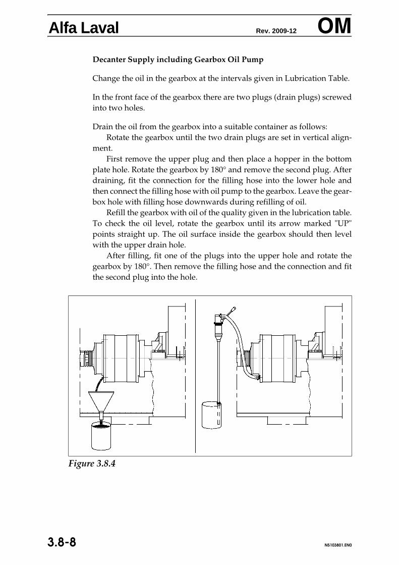
Alfa Laval Rev. 2009-12 OM
Decanter Supply including Gearbox Oil PumpChange the oil in the gearbox at the intervals given in Lubrication Table.
In the front face of the gearbox there are two plugs (drain plugs) screwedinto two holes.
Drain the oil from the gearbox into a suitable container as follows:Rotate the gearbox until the two drain plugs are set in vertical align-
ment.First remove the upper plug and then place a hopper in the bottom
plate hole. Rotate the gearbox by 180° and remove the second plug. Afterdraining, fit the connection for the filling hose into the lower hole andthen connect the filling hose with oil pump to the gearbox. Leave the gear-box hole with filling hose downwards during refilling of oil.
Refill the gearbox with oil of the quality given in the lubrication table.To check the oil level, rotate the gearbox until its arrow marked "UP"points straight up. The oil surface inside the gearbox should then levelwith the upper drain hole.
After filling, fit one of the plugs into the upper hole and rotate thegearbox by 180°. Then remove the filling hose and the connection and fitthe second plug into the hole.
Figure 3.8.4
3.8-8 N5103801.EN0

Alfa Laval Rev. 2009-11 OM
3.9 Recommended service intervals
Major service is replacement of all bearings and all seals while intermedi-ate (or minor) service is replacement of seals only.
It is difficult give a precise answer how often major service and interme-diate service must be done because the wear and contamination risk isboth application and installation related. Therefore it must be based on ac-tual application experience. As a rule of thumb it is recommended to carryout a major service every second year and a minor service in the interme-diate year. For some applications such as applications with high temper-atures, frequent CIP, contaminated environment and for decanters withparing disks, a major service at least once every year is recommended.
3.9-1NALL3901.EN0

Alfa Laval Rev. 2009-11 OM
Maintenance Table1) 2000 hours, unless specified otherwise in separate motor manual.
contd...
Recommended Intervals for MaintenanceItem Interval
Gearbox Oil Leakage CheckChange lip seal(s) at sunwheelshaft(s) if leaking
Monthly
Oil Level Check 1000Oil Change 2000
GearboxSpline Shaft Lubricate splines At each major service
Motor(s) Lubrication 20001) V-belts Tightening up and Check 2000
Change 16000 Bowl Check for wear and corrosion.
For decanters operating at high tempera-tures and/or high chloride levels in feed,check bolts connecting bowl section forcorrosion and stress corrosion cracks.See safety instructions for details.
1000
Solids Discharge Wear Protection
CheckIf damaged or excessively worn,fit new immediately.
1000
Safety Equipment Check functioning of: All alarm devices Safety equipment
2000
Labels Check: Nameplate and warning labels.Replace if not readable.
2000
Foundation bolts Check tightening 4000 Vibration dampers Check
Fit new, if necessary. 4000
Table 3.9.1
3.9-2 NALL3901.EN0

Alfa Laval Rev. 2009-04 OM
4 Disassembling and Assembling
WARNING Do not make any disassembly/assembly operations on the decanterunless the main power is shut off, and the disconnected main switchis locked with a safety lock.
Replacing parts
To ensure trouble-free operation of the decanter, great caremust be taken during replacement of parts:
• Contacting and sliding surfaces, as well as O-rings andseals must be care fully cleaned.
• Always place removed parts on a clean, soft surface toavoid scratching the surfaces.
• Ensure that screws used to pull parts from each otherhave smooth ends.
O-rings, Seals, and Gaskets
Check O-rings, seals and gaskets for defects.
Check that O-ring grooves and sealing surfaces are clean.
After replacing an O-ring, check that it fills the groove com-pletely and that it is not twisted.
Ensure that seals are mounted with the open end pointing thecorrect way. See illustrations.
4.0-1NALL4001.EN0

Alfa Laval Rev. 2009-04 OM
Special tools Always use the recommended special tools for removing,disassembling, assembling, and mounting the bowl. In case ofnegligence of this point, Alfa Laval accepts no liability for pos-sible damage to the parts.Alfa Laval supplies a variety of special tools and accesso-ries to facilitate maintenance of the decanter. See volume SPC(Spare Parts Catalogue).
When lifting the decanter assembly use theslings specified on the dimensioned drawing.
When Lifting Minor Decanter Parts by Strapsalways use lifting straps having a load capacity of minimum1000 kg (2200 lbs).
Vibration Dampers Check regularly and change those crumbled and damperswhose rubber has swelled or cracked. Do not run the decanterif any of its dampers is defective.
4.0-2 NALL4001.EN0
Alfa Laval Rev. 2009-04 OM
Spare Parts KitsAlfa Laval supplies three types of spare parts kits for the de-canter:
The intermediate kit for main bearings and conveyorbearings, respectively, contain rubber parts for the main bear-ings and the conveyor bearings.
The major kit for main bearings and conveyor bearings, re-spectively, contains parts necessary for the complete overhaulof the decanter. It includes all sealing components and bear-ings. See volume SPC (Spare Parts Cataloque).
The gearbox kit includes the lip seal for the sun wheel andthe O-ring between the splined nave and the gearbox cover.
4.0-3NALL4001.EN0

Alfa Laval Rev. 2007-06 OM
4.1SFigure 4.1.1
4.1-0 N5104101.EN0

Alfa Laval Rev. 2007-06 OM
4.1 Rotating Assembly4.1.1 Remove Bowl (Figs. 4.1.1 and 4.1.2)
WARNING Do under no circumstances loosen or remove the upper casing whilethe bowl is rotating.
Disassemble the main drive according to instructions in sec-tion 4.5.1.
Disassemble the back drive according to instructions in sec-tion 4.6.1.
Remove the four screws [2] and the wear liner [3]. Table 4.1.1
4.1-1N5104101.EN0

Alfa Laval Rev. 2007-06 OM
Figure 4.1.2
4.1-2 N5104101.EN0

Alfa Laval Rev. 2007-06 OM
Remove the pillow block dowel pin protector caps [5] andwithdraw dowels as follows using the Shaft and Sliding Ham-mer portion of the Dowel Sleeve Extractor Tool* (see Figure4.1.2):Assemble the Sliding Hammer [6] to the Shaft portion of theDowel Sleeve Extractor [7]. Engage the female thread in theend of the shaft [7] over the protruding thread of the dowelpin [8] and screw home securely.
Withdraw the dowel pin [8] by impact of the sliding hammeragainst the stop nut at the top of the shaft.
Repeat the operation on each of the dowels.
Extract the dowel pin outer sleeves [9] as follows using thecomplete Dowel Sleeve Extractor Tool* (see Figure 4.1.2)..
Assemble the Sliding Hammer [6] to the Shaft portion of theextractor [7] and attach the Lifter Assembly to the femalethread in the end of the shaft.
Slide the Eccentric Sleeve [10] along the Lifter [11] until it con-tacts the cap [12].
Holding the extractor assembly upright, insert the Lifter [11]down through the bore of the dowel sleeve [9] as far as possi-ble, then push the eccentric sleeve [10] down into the bore ofthe dowel sleeve [9] to lock the lifter [11] into the dowel sleeverecess [9].
Extract the dowel sleeve [9] by impact of the sliding hammeragainst the stop nut at the top of the shaft [7].
Repeat the operation on each of the dowel sleeves.
Remove the eight screws [4] holding the pillow blocks.
* For P/N, see Spare Parts Catalogue
4.1-3N5104101.EN0

Alfa Laval Rev. 2007-06 OM
Now remove the bowl assembly by means of the lifting tool.Place the tool on top of the bowl at the centre of gravityand pull the tow straps around the bowl. Now pull the longend through the short end.
Pull the tool around the bowl to the underside and placethe long ends of the straps in the hook of the crane, as shownin Figure 4.1.3.
ATTENTION Check that the two bars are placed underneath the bowl and the twostraps are placed tightly around the bowl.
The individual design of both bowl and conveyor means thateach bowl has its own centre of gravity and, as a consequenceof this, that the axial point on the lifting tool corresponding tothe bowl centre of gravity displaces accordingly. To find bowlcentre of gravity, proceed as follows:
Place the lifting tool around the bowl and lift the bowlcarefully, to see how the bowl balances.
If the bowl is not in balance, place the bowl in horizontalposition on the frame, move the lifting tool closer to the heavyend of the bowl and lift the bowl carefully again.
Repeat this procedure until the bowl is in balance.
Carefully lift the bowl assembly off the lower casing and placeit on the lifting tool.
4.1-4 N5104101.EN0

Alfa Laval Rev. 2007-06 OM
4.1.2 Install Bowl (Figs. 4.1.1 and 4.1.2)
When installing the bowl, clean the pillow block contact sur-faces and the frame before lowering the bowl into place.
Pull the tow straps around the bowl and pull the long endthrough the short end.
Place them in the hook of the crane as shown in Figure4.1.3.
Lower the bowl assembly onto the frame.
ATTENTION If the gearbox is equipped with a reaction arm, as shown in Figure4.1.3, then be very careful not to damage it when lowering the bowlassembly.Either remove the reaction arm during assembly, or turn it upwards.
After the bowl has been placed and the pillow blocks aligned,the dowel pins [9] and [8] must be driven in.
Fit the dowel pin protector caps [5].
Tighten the eight screws [4] securing the pillow blocks to atorque of 385 Nm (3404 in-lbs).
Install the wear liner [3] and secure with the four screws [2].
Assemble the main drive according to the instructions in sec-tion 4.5.2.
Figure 4.1.3
4.1-5N5104101.EN0

Alfa Laval Rev. 2007-06 OM
Figure 4.1.4
4.1-6 N5104101.EN0

Alfa Laval Rev. 2007-06 OM
4.1.3 Remove Large End Hub (Fig. 4.1.4)This procedure describes how to remove the large end hubwith the gearbox assembled to it. For removal of the gearboxfrom the large end hub, see section 4.1.7.
ATTENTION When removing the large end hub [1], always suspend it with a slingfrom a hoist or the like, to avoid excessive load to the needlebearing [11]. Place a sling around both sides of the pillow block.
Remove 29 of the 30 long screws [3], loosen the last one, andleave it in place until the end hub [1] is ready to be removed.
The end hub can now be jacked out: Using the three jackingscrews [4], clear it of the bowl.
Be careful not to damage the needle bearing [11].
Remove the loosened long screw [3] left in place and carefullypull out the end hub [1].
Turn the three jacking screws [4] back to their original posi-tion. They must not stick out through the large end hub con-tact surface when the hub is re-installed.
4.1.4 Install Large End Hub (Fig. 4.1.4)
This procedure describes how to install the large end hub withthe gearbox assembled to it. For assembling the gearbox to thelarge end hub, see section 4.1.8.
ATTENTION When mounting the large end hub [1], always suspend it with asling from a hoist or the like, to avoid excessive load to the needlebearing [11]. Place a sling around both sides of the pillow block.
Grease the outside of the O-rings [8], [106] and [107].Place the large end hub [1] on the bowl, being careful not
to damage the needle bearing [11].
Fit the 30 screws [3] and tighten them to a torque of 44 Nm(389 in-lbs).
Fasten the three jacking screws [4].
4.1-7N5104101.EN0

Alfa Laval Rev. 2007-06 OM
Figure 4.1.5
4.1-8 N5104101.EN0

Alfa Laval Rev. 2007-06 OM
4.1.5 Remove Small End Hub (Fig. 4.1.5)ATTENTION When removing the small end hub [1], always suspend it with asling from a hoist or the like, to avoid excessive load to the ballbearing [3]. Place a sling around both sides of the pillow block.
Loosen the twelve screws [13] and remove them.
Lossen the eight screws [20] and remove them.
The hub can now be carefully pulled out. Use, if necessary, aplastic hammer on the edge of the hub to loosen it.
4.1.6 Install Small End Hub (Fig. 4.1.5)
ATTENTION When mounting the small end hub [1], always suspend it with asling from a hoist or the like, to avoid excessive load to the ballbearing [3]. Place a sling around both sides of the pillow block.
Fit the conveyor according to instruction given in section 4.4.2.
Grease the outside of the O-rings [102] and [104].
Fill up with grease the ball bearing outer race [3] and distrib-ute the grease with the fingers.
Place the small end hub [1] on the bowl. To align the holes inthe retaining ring [2] with the holes in the hub [1], use a pin [A]as indicated in Figure 4.1.6, and secure the ring [2] with thescrews [13]. Replace the pin [A] with a screw [13] when theholes are aligned. Secure the hub with two of the screws [20],and be careful not to damage the ball bearing [3] during thisprocess.
Fit the remaining six screws [20] and tighten them to a torqueof 76 Nm (672 in-lbs).
Figure 4.1.6
4.1-9N5104101.EN0
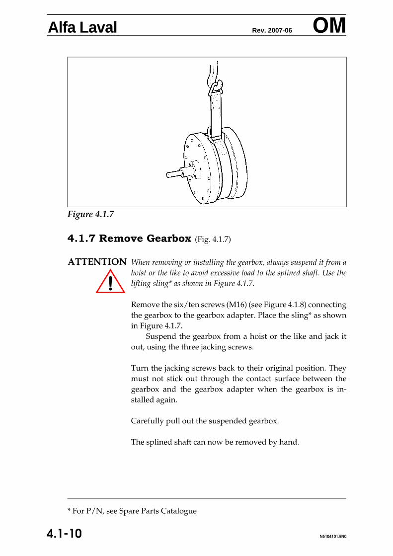
Alfa Laval Rev. 2007-06 OM
4.1.7 Remove Gearbox (Fig. 4.1.7)
ATTENTION When removing or installing the gearbox, always suspend it from ahoist or the like to avoid excessive load to the splined shaft. Use thelifting sling* as shown in Figure 4.1.7.
Remove the six/ten screws (M16) (see Figure 4.1.8) connectingthe gearbox to the gearbox adapter. Place the sling* as shownin Figure 4.1.7.
Suspend the gearbox from a hoist or the like and jack itout, using the three jacking screws.
Turn the jacking screws back to their original position. Theymust not stick out through the contact surface between thegearbox and the gearbox adapter when the gearbox is in-stalled again.
Carefully pull out the suspended gearbox.
The splined shaft can now be removed by hand.
Figure 4.1.7
* For P/N, see Spare Parts Catalogue
4.1-10 N5104101.EN0

Alfa Laval Rev. 2007-06 OM
4.1.8 Install Gearbox (Fig. 4.1.8)Apply an ample amount of grease* to the splined shaft and thesplined hub in the conveyor.
Push the gearbox assembly with splined shaft carefullyinto place.
Rotate the sunwheel shaft a few turns, to make the splinesengage.
* For P/N, see Spare Parts Catalogue, Section TOOLS AND LUBRICANTS
3.5 kNm Gearbox Insert the six screws assembling the gearbox adapter to thegearbox and tighten them to a torque of 197 Nm (1743 in-lbs)in the sequence indicated in Figure 4.1.8.
Tighten the three jacking screws.
8.0 kNm Gearbox12.0 kNm Gearbox
Insert the 10 screws (M16) assembling the gearbox adapter tothe gearbox and tighten them to a torque of 197 Nm (1743in-lbs). No certain tinghtening sequence to be followed whentightening the screws
Figure 4.1.8
4.1-11N5104101.EN0
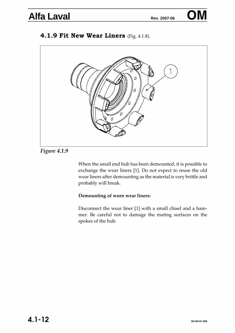
Alfa Laval Rev. 2007-06 OM
4.1.9 Fit New Wear Liners (Fig. 4.1.8).When the small end hub has been demounted, it is possible toexchange the wear liners [1]. Do not expect to reuse the oldwear liners after demounting as the material is very brittle andprobably will break.
Demounting of worn wear liners:
Disconnect the wear liner [1] with a small chisel and a ham-mer. Be careful not to damage the mating surfaces on thespokes of the hub.
3.
Figure 4.1.9
4.1-12 N5104101.EN0

Alfa Laval Rev. 2007-06 OM
Mounting of new wear liners:- Clean the surface for glue residues, and thoroughly cleanall surfaces that are to be glued, on spokes and wear liners[1] with acetone.
- Apply Araldite 2014 zigzag-wise on the inner side of thewear liner [1].
- The wear liner [1] is placed on the spoke and rotated backand forth until it feels as if it is floating. Then it is pushedinto place and secured with a rubber band. Be careful thatthe gap is completely filled with glue.
- Remove excess Araldite.
Hardening time: 3.5 hours at 20oC (68oF)0.5 hour at 60oC (140oF)5 min. at 100oC (212oF)
4.1-13N5104101.EN0

Alfa Laval Rev. 2008-01 OM
4.2Figure 4.2.1
4.2-0 N5104201.EN0

Alfa Laval Rev. 2008-01 OM
4.2 Main Bearings (Fig. 4.2.1)4.2.1 Disassemble Main Bearing Large End
Prior to disassembling the main bearing large end, the gearbox mustbe removed according to instructions given in section 4.1.7.
Remove the 10 screws [15].Using two of them as jacking screws, pull off the gearbox adapt-
er [2], tightening the jacking screws equally to avoid pulling out theadapter [2] askew.
Remove the four long screws [18] and the four short screws [17].
Now remove by hand the complete bearing assembly consisting ofpillow block [1], roller bearing outer race [11], and ring [9].
Use a hammer and a brass mandrel to remove the roller bearing outerrace [11], taking care that the mandrel does not damage the pillowblock [1].
Table 4.2.1
4.2-1N5104201.EN0
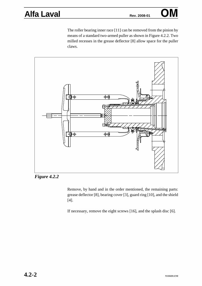
Alfa Laval Rev. 2008-01 OM
The roller bearing inner race [11] can be removed from the pinion bymeans of a standard two-armed puller as shown in Figure 4.2.2. Twomilled recesses in the grease deflector [8] allow space for the pullerclaws.Remove, by hand and in the order mentioned, the remaining parts:grease deflector [8], bearing cover [3], guard ring [10], and the shield[4].
If necessary, remove the eight screws [16], and the splash disc [6].
Figure 4.2.2
4.2-2 N5104201.EN0

Alfa Laval Rev. 2008-01 OM
4.2.2 Assemble Main Bearing Large End (Fig. 4.2.1)Fit by hand the splash disc [6] on the pinion.Insert an tighten the eight screws [16].
Fit the O-Ring [35] into the guard ring [10], and fit the guard ring[10] on the pinion, its two holes pointing outwards.
Fit the O-Ring [34] on the shield [4] and place the shield on the guardring [10]. Make sure its 'cut edge' points downwards.
Push the bearing cover [3] on the guard ring [10], its grease dischargepointing downwards, and then fit the grease deflector [8] on the pin-ion.
Heat the main bearing inner race [11] to a temperature of 80°C(175°F) by means of an induction heater or in an oven and push it onthe pinion as far it goes; it must seat fully against the grease deflector[8] all around.
Insert the roller bearing outer race [11] into the pillow block [1] andgrease the rollers.
Then fit the ring [9] including the O-Ring [12] and push careful-ly the assembly on the main bearing inner race [11].
4.2-3N5104201.EN0

Alfa Laval Rev. 2008-01 OM
Insert the four long screws [18] attaching the bearing cover [3] to thepillow block [1], and the four short screws [17] securing the shield[4].Tighten all eight screws.
Carefully clean the contact surfaces between the gearbox adapter [2]and the pinion.
Place the gearbox adapter [2] on the large end pinion, aligningthe axial hole in the adapter and the guide pin on the end surface ofthe pinion.
Fit the 10 screws [15]. Tighten them to a torque of 47 Nm (416 in-lbs), tightening them crosswise a few times to ensure tightening of all10 screws to the correct torque.
Install the gearbox according to the instructions given in section4.1.8.
4.2-4 N5104201.EN0

Alfa Laval Rev. 2008-01 OM
this page intentionally left blank
4.2-5N5104201.EN0

Alfa Laval Rev. 2008-01 OM
Figure 4.2.3
4.2-6 N5104201.EN0

Alfa Laval Rev. 2008-01 OM
4.2.3 Disassemble the Main Bearing Small End(Fig. 4.2.3)
Remove the eight screws [36].
Using two M10 jacking screws, pull off the pulley [27], tighteningthe jacking screws equally, to avoid pulling the pulley [27] askew.
Remove the four short screws [17].
Fit the puller tool* on the pillow block as shown in Fig. 4.2.4.
Then pull off the assembly consisting of: Pillow block [21], ballbearing [26], ring [9], V-Ring holder [8], and the bearing cover [3].
Disassemble the pillow block: Remove, in the following order, thefour long screws [31], the bearing cover [3], the V-Ring holder [8],and the ring [9].
Figure 4.2.4
* For P/N, see Spare Parts Catalogue
4.2-7N5104201.EN0

Alfa Laval Rev. 2008-01 OM
Use a hammer and a brass mandrel to remove the ball bearing [26].Take care that the mandrel does not damage the pillow block [21].Remove by hand the guard ring [10] and the shield [23].
4.2.4 Assemble Main Bearing Small End (Fig. 4.2.3)
Fit the O-Ring [34] on the shield [23] and place it on the pinion.
Fit the guard ring [10] including the O-ring [35] on the pinion, its twoholes pointing outwards.
Push the bearing cover [3] on the guard ring [10], grease dis-charge pointing downwards, and then fit the V-Ring holder [8] in-cluding V-ring [7] and O-Ring [22] on the pinion.
Do not apply any lubricant at all to the V-ring [7] when fittingit!
4.2-8 N5104201.EN0

Alfa Laval Rev. 2008-01 OM
Insert the ball bearing [26] into the pillow block [21] and grease theballs.Apply a thin layer of anti-fretting corrosion paste* to the smallend hub pinion.
Then fit the ring [9] including the O-Ring [12] and then press,with the pressure acting on the inner race of the ball bearing [26], theassembly on the pinion by means of the special tool* as shown inFig. 4.2.5.
ATTENTION The ball bearing must be exchanged after disassembly as it may havebeen damaged during removal.
Insert the four long screws [31] attaching the bearing cover [3] to thepillow block [21] and the four short screws [17] securing the shield[23].
Tighten all eight screws.
* For P/N, see Spare Parts Catalogue
Figure 4.2.5
4.2-9N5104201.EN0

Alfa Laval Rev. 2008-01 OM
Make sure that the O-Rings lie correctly in their grooves, and thatthey are not damaged.Fit the pulley [27].
Fit the eight screws [36] and tighten them to a torque of 44 Nm (389in-lbs), tightening them crosswise a few times, to ensure tighteningof all eight screws to the correct torque.
Install the small end hub according to the instructions given in sec-tion 4.1.6.
4.2-10 N5104201.EN0

Alfa Laval Rev. 2008-01 OM
this page intentionally left blank
4.2-11N5104201.EN0

Alfa Laval Rev. 2006-10 OM
4.3yFigure 4.3.1
4.3-0 N5104301.en0

Alfa Laval Rev. 2006-10 OM
4.3 Conveyor Bearings (Fig. 4.3.1)4.3.1 Disassemble Conveyor Bearing Large End
Remove the large end hub according to instructions given insection 4.1.3.
Remove the lock ring [12].
Remove the needle bearing inner race [11] by means of astandard two-armed puller tool as shown in Figure 4.3.2.
Figure 4.3.2
4.3-1N5104301.en0

Alfa Laval Rev. 2006-10 OM
Remove the snap ring ([9] in figure 4.3.1).Using a standard two-armed puller* as shown in Figure4.3.3, pull off the needle bearing outer race [11] .
* For P/N, see Spare Parts Catalogue
Figure 4.3.3
4.3-2 N5104301.en0

Alfa Laval Rev. 2006-10 OM
4.3.2 Assemble Conveyor Bearing Large End(Fig. 4.3.1)
If the end flange [10] has been removed and disassembled, as-semble the parts in the following order:
Fit the O-ring [105] in the end flange [10].Insert the end flange [10]. Fit the twelve screws [7] and
tighten them to a torque of 44 Nm (390 in-lbs).
Heat the needle bearing inner race [11] by means of an induc-tion heater or in an oven to approximately 80°C (175°F) and fitit onto the inner pinion; be sure it seats fully against the shoul-der of the pinion. Fit the lock ring [12].
Fit the needle bearing outer race [11] onto the large end hub.Fit the snap ring [9].
Fit the three O-rings [8], [106], and [107] and grease them.
Fill up with grease the needle bearing outer race [11] and dis-tribute the grease with the fingers.
Place the conveyor into the bowl according to the instructionsgiven in section 4.4.2.
Install the large end hub according to the instructions given insection 4.1.4.
4.3-3N5104301.en0

Alfa Laval Rev. 2006-10 OM
Figure 4.3.4
4.3-4 N5104301.en0

Alfa Laval Rev. 2006-10 OM
4.3.3 Disassemble Conveyor Bearing Small End(Fig. 4.3.4)
Remove the small end hub according to the instructions givenin section 4.1.5.
Remove the sixteen screws [4] and the ring [2].
Use a standard two-armed puller tool*, as shown in Fig. 4.3.5,with the retaining ring [1] as tractor, to pull off the bearing [3].
* For P/N, see Spare Parts Catalogue
R
Figure 4.3.5
4.3-5N5104301.en0

Alfa Laval Rev. 2006-10 OM
4.3.4 Assemble Conveyor Bearing Small End(Fig. 4.3.4)
Thoroughly clean the retaining ring [1] and insert the O-rings[6], [102], [103], and [104].
Grease the O-rings [6], [102], [103], and [104].
Place the retaining ring [1] on the conveyor pinion, and push itinto place.
Fit the inner half of the ball bearing inner race [3] onto the pin-ion.
Fill up with grease the ball bearing outer race [3] and push itonto the ball bearing inner race [3]. Fit the remaining half ofthe inner race.
Fit the O-ring [101] into the ring [2] and grease it a little.
Fit the ring [2] on the pinion and secure it with the sixteenscrews [4]. Tighten the screws [4] to a torque of 44 Nm (390 in-lbs).
Insert the conveyor into the bowl according to the instructionsgiven in section 4.4.2.
Install the small end hub according to the instructions given insection 4.1.6.
4.3-6 N5104301.en0

Alfa Laval Rev. 2010-02 OM
4.44.4 Conveyor
4.4.1 Remove Conveyor from Bowl (Fig. 4.4.1)
Remove the large end hub according to instructions given in section4.1.3.
ATTENTION Slimline decanters: Remove the small end hub according to the instructions given in sec-tion 4.1.5.
Place the bowl (without large end hub) horizontally on two woodentrestles or the like: Attach the lifting tool* to the large end of the con-veyor as shown in Figure 4.4.1.
Connect the shackle to the hoist and fit the shackle into the lifting toolhole. Because of its individual design each conveyor has its own centreof gravity. As consequence of this the axial point on the lifting tool cor-responding to the conveyor centre of gravity is not the same for allconveyors. To find the actual conveyor centre of gravity, proceed asfollows:
Fit the shackle in the lifting tool centre hole and lift the conveyorcarefully, to see how the it balances.
If the conveyor is not in balance, then insert the shackle into thenext lifting tool hole nearer to the heavy end of the conveyor and liftthe conveyor carefully again.
Figure 4.4.1
* For P/N, see Spare Parts Catalogue
4.4-1N5104401.EN0

Alfa Laval Rev. 2010-02 OM
Repeat this procedure until the conveyor is in balance and markthe centre of gravity hole of the lifting tool, to facilitate future disas-sembling and assembling.
Carefully pull out the conveyor.
4.4.2 Insert Conveyor into Bowl (Fig. 4.4.1)
Place the bowl horizontally on two wooden trestles or the like: Attachthe lifting tool* to the large end of the conveyor as shown in Figure4.4.1.
Connect the shackle to the hoist and fit the shackle into the lifting toolhole where the conveyor will be in balance when lifted and push itcarefully into the bowl.
CAUTION Be careful not to cut your fingers, when pushing the conveyor intothe bowl.
Install large and small end hubs according to the instructions given insections 4.1.4 and 4.1.6, respectively.
* For P/N, see Spare Parts Catalogue
Figure 4.4.2
4.4-2 N5104401.EN0


Alfa Laval Rev. 2007-02 OM
4.5Figure 4.5.1
4.5-0 N5104501.EN0

Alfa Laval Rev. 2007-02 OM
4.5 Main Drive4.5.1 Disassemble Main Drive (Fig. 4.5.1)
Remove the sixteen screws and washers [31] and [32] holdingthe upper casing and open the casing [3].
Remove the four screws [30] and remove the feed tube [33].
Loosen the four screws [14] and [17] and elevate the motorbracket [10] by means of the two elevating screws [18].
Remove the five V-belts from the pulley.
4.5-1N5104501.EN0

Alfa Laval Rev. 2007-02 OM
Figure 4.5.2
4.5-2 N5104501.EN0

Alfa Laval Rev. 2007-02 OM
4.5.2 Assemble Main Drive (Fig. 4.5.1)If the decanter is equipped with a main motor placed on fourdampers and changing of this motor is required, then proceedas follows:
Refer to Fig. 4.5.1 for identification of parts.
1. Tighten the belts to the value prescribed in Table 4.5.2 (or4.5.1, if new belts are installed too).
2. Measure the distances A and B.
3. Loosen the belts again and turn the bolt [8] until the meas-uring results of A and B are the same when retighteningthe belts. One turn is equal to 1.75 mm (quite 1/16 inch).
4. Retighten the belts to the prescribed value and checkwhether the A and B measurements are identical. If not,repeat the procedure.
5. Tighten the lock nut [6].
Required weight of motors placed on four dampers: 250-700 kg (550-1542 lbs).
Align the pulleys so that their placing is within 3 mm (1/8inch) as shown in Figure 4.5.2.
Install the five V-belts in the grooves of the pulleys andtighten them by means of the two screws [18].
Tighten the V-belts as per instructions given in section4.5.3.
Secure the motor bracket [10] with the four screws [14]and [17], and tighten them to a torque of 665 Nm (5883 in-lbs).
Install the feed tube [33] and tighten the four screws [30].
Install the upper casing [3] and secure it with the sixteenscrews and washers [31] and [32].
4.5-3N5104501.EN0

Alfa Laval Rev. 2007-02 OM
4.5.3 Tighten V-belts, Belt Tension Tables
Using the tester illustrated in Figure 4.5.3 above, adjust thebelt tension as follows:
1. See how to hold the tension tester and choose one of theways a, b, or c as shown in Figure 4.5.4.
Figure 4.5.3
1 Indicator Arm2 Rubber Finger Loop3 Pressure Surface4 Pocket Clip5 V-belt6 Pressure Spring
4.5-4 N5104501.EN0

Alfa Laval Rev. 2007-02 OM
2. Position the tester on the belt midway between the twopulleys with the flange on the bottom against the upperedge of belt.
Take care that the indicator is completely pusheddown in the tester body.
Place the tester II (without flange) in the middle of thebelt and parallel with the belt sides.
3. Position the tester loosely on the belt to be measured andpush slowly with one finger in the above way (Fig. 4.5.4,A, B, C) on the pressure surface.
4. Avoid contact of tester with more than one finger duringthe measuring process.
5. When your hear a CLICK, stop pressing immediately; theindicator arm remains in measure position.
6. Remove tester carefully so that the indicator arm is notmoved and read the belt tension where the top surface ofthe indicator arm crosses the scale as shown in Figure4.5.5.
Figure 4.5.4
Figure 4.5.5
4.5-5N5104501.EN0

Alfa Laval Rev. 2007-02 OM
7. For safe reading mark the spot of the upper side of the in-dicator with a thumbnail on the scale and then turn thetester sideways.
8. Increase or decrease the belt tension depending on themeasuring result until it is within the desired tension. Seetable below.
For selection of belt and pulley combinations, see Spare Parts Catalogue.
BELT TENSION - Tightening of New Belts
Motor Power Bowl Speed [r p m]
[kW] [HP] 2900 / 3050 3250
45 (60) 650-700 N 700-750 N
55 (75) 650-700 N 700-750 N
75 (100) 650-700 N 700-750 N
90 - - 750-800 N (50 Hz)
90 - - 700-750 N (60 Hz)
- (125) - 750-800 N (60 Hz)
Table 4.5.1
BELT TENSION - Tightening of Used Belts
Motor Power Bowl Speed [r p m]
[kW] [HP] 2900 / 3050 3250
45 (60) 500-550 N 500-550 N
55 (75) 500-550 N 500-550 N
75 (100) 500-550 N 500-550 N
90 - - 550-600 N (50 Hz)
90 - - 500-550 N (60 Hz)
- (125) - 600-650 N (60 Hz)
Table 4.5.2
4.5-6 N5104501.EN0


Alfa Laval Rev. 2006-10 OM
1.2Figure 1.2.1
1.2-0 N5104601.EN0
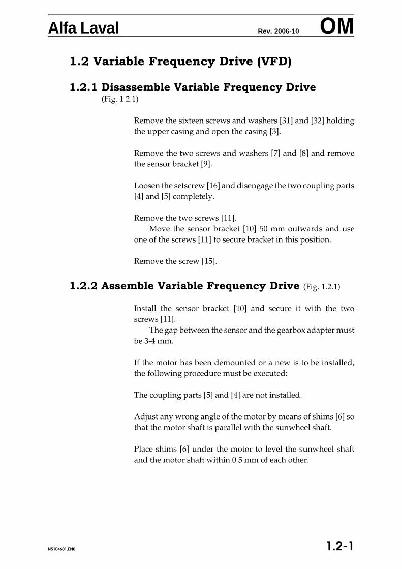
Alfa Laval Rev. 2006-10 OM
1.2 Variable Frequency Drive (VFD)1.2.1 Disassemble Variable Frequency Drive(Fig. 1.2.1)
Remove the sixteen screws and washers [31] and [32] holdingthe upper casing and open the casing [3].
Remove the two screws and washers [7] and [8] and removethe sensor bracket [9].
Loosen the setscrew [16] and disengage the two coupling parts[4] and [5] completely.
Remove the two screws [11].Move the sensor bracket [10] 50 mm outwards and use
one of the screws [11] to secure bracket in this position.
Remove the screw [15].
1.2.2 Assemble Variable Frequency Drive (Fig. 1.2.1)
Install the sensor bracket [10] and secure it with the twoscrews [11].
The gap between the sensor and the gearbox adapter mustbe 3-4 mm.
If the motor has been demounted or a new is to be installed,the following procedure must be executed:
The coupling parts [5] and [4] are not installed.
Adjust any wrong angle of the motor by means of shims [6] sothat the motor shaft is parallel with the sunwheel shaft.
Place shims [6] under the motor to level the sunwheel shaftand the motor shaft within 0.5 mm of each other.
1.2-1N5104601.EN0

Alfa Laval Rev. 2006-10 OM
Install the coupling part [5] and engage it completely on themotor shaft. Now install the other part of the coupling on thesunwheel shaft and put the two coupling parts into engagedposition, leaving an axial play of 3-4 mm (1/8 inch) betweenthem, and tighten the setscrews.Install the sensor bracket [9] and fasten with the two screws [7]and washers [8].
Make sure that the rubber bushing [14] is placed correctly, andfit the screw [15].
Install the upper casing [3] and secure with the sixteen screwsand washers [31] and [32].
1.2-2 N5104601.EN0

5.0-0NALL5001.EN0
Alfa Laval Rev. 1994-09 OMy
5 Supplementary Documentation


Alfa Laval Rev. 2006-11 OMSupplementaryTechnical Details
4.2
0.10.2
Figure 1
0 WEAR LINERS ALLSUPWL.EN0

Alfa Laval Rev. 2006-11 OMSupplementaryTechnical Details
Wear liner assembly (figure 1)
1 Rough-grind the hatched surface of the feed rotor to get arugged surface.
2 Degrease the grinded surfaces with Chesterton 277.
3 Apply an even layer of approx. 2-3 mm of the ready-mixed ARC 858 on both feed rotor and wear liner.
4 Turn the wear liner into place and fix it with securingplates. Mind to turn the wear liner correctly. Disperse ex-cess composite so that it fills the gap between feed rotorand wear liner.
Wear liner disassembly
I. Remove the screws in the securing plates and remove theplates.
II. Attempt to loosen the wear liner from the backside with abrass mandrel or the like. Heating to 120-130o C might benecessary.
III. After removal of the wear liner, the hatched area of thesurface is cleaned, as described under assembly.
OBS! Wear liners in WC are at great risk of breaking, when at-tempted removed.
WEAR LINERS 1ALLSUPWL.EN0

h
SP Polyglot Edition
SPARE PARTS CATALOGUE
RESERVDELSKATALOGERSATZTEILLISTECATALOGUE DE PIECES DERECHANGECATALOGO DE REPUESTOCATALOGO DI PEZZI DIRICAMBIORESERVEDELSKATALOG
Decanter Centrifuge
Alfa Laval
FRONT


Decanter Centrifuge Data Sheet
Decanter Specification, Type ALDEC G2-95 Machine No.: 5024795 Date of issue: 2010-09-15
Specification: 882051002-0
Process liquid: Min. 0°C (32°F) - max. 60°C (140°F)
Max. density of compact wet cake at max. bowl speed: 1.5 kg/dm³ Bowl Maximum main speed: 3250 rpm Bowl length: 2244 mm Bowl diameter: 510 mm Beach angle: 10° Solids discharge type: 360°-type with 8 wear liners Solids discharge radius: 138 mm Solids transportation aids, cylindrical section: Ribs Solids transportation aids, taper section: Ribs Material - hubs: AL 111 2377 (Duplex stainless steel) Material - bowl shell: AL 111 2327 (Lean duplex stainless steel) Attention: If the
product is corrosive; Please see note in the description field on top of this document
Material - bolts: A4-80 (AISI 316) Material - seals: Liquid outlet, type: 6 Liquid outlet, radius: 130 mm (fitted from factory: 139 mm)
Conveyor Material - flights: AL 111 2349 (AISI 316) Material - hub: AL 111 2349 (AISI 316)
Wear Protection Bowl solids discharge: Wear liner in tungsten carbide. 8 pieces Part No.
61233941-03 Bowl feed zone liner: Conveyor flights: Tungsten Carbide Tiles / PTA Conveyor feed zone: Tungsten Carbide wear liners Frame / casing: Wear liner in upper casing
Frame and Casing Material - casing / cover: Stainless steel (AISI 316) Inside surface of casing: Liners of stainless steel at discharge areas - painting in
neutral compartment. Gaskets / seals - casing:

Drives Power supply: 3 x 480V / 60 Hz Gearbox, type: Planetary - 2-stage DD Gearbox, max. torque: DD 12.0 kNm Gearbox, ratio: 1:100.8 Back drive: Variable Frequency Drive 30 Hp NEMA (460V, 60Hz) -
max. diff. speed 17.5 rpm at 12 kNm - diff. speed 29.8 rpm at max. 7.1 kNm (Back drive motor, 460VD, 1800rpm, 60Hz,NEMA 286T, part no. 61195635-50)
Back drive parts: Operating main speed: 3250 rpm (NEMA) Max. diff. speed and torque (at operating speed):
G-force at operating speed: 3011 G Main motor: 75 Hp Baldor 460VD Y/D-VFD (365) foot heating –
part No. 61195625-51 Main motor, protection:
Documents & Drawings Manuals, language: Manuals in English Dimension drawing: 61242878 Diagram, decanter junction box: 61211283
Spare Parts Important: When ordering spare parts, always state:
Machine number and type indicated above Part number and designation Quantity
The decanter centrifuge complies with the essential health and safety requirements of council directives 2006/42/EC Machinery Directive
2006/95/EC Low Voltage Directive
2004/108/EC EMC Directive To meet the requirements, the harmonised standard EN 12547 has been used. The technical file for decanter centrifuge is compiled and retained by Product Centre Decanters, Alfa Laval Copenhagen A/S, Maskinvej 5, DK-2860 Søborg, Denmark. Authorised person: Jan Cederkvist, Mechanical Technology.

DATASHEET
Noise Declaration Noise emission data for the decanter declared in accordance with the re-quirements in EN ISO 4871 and EN12547:
LwAd : Declared A-weighted sound power level from the decanter
LpAd : Declared A-weighted emission sound pressure level in a free field over a re-flecting plane at 1 m distance from the decanter
Uncertainty on declared values : LwAd : KwA=2 dB
LpAd : KpA=4 dB
The noise does not contain significant impulsive or tonal components and the peak C-weighted instantaneous sound pressure level LpCpeak is below 130 dB(C) at all operat-ing speeds.
The emission sound power level is measured according to ISO 9614-2 while operatingthe decanter with water as process medium. The sound pressure level is determinedfrom the measured sound power level according to EN ISO 11203.
The sound pressure level can vary –1dB to 2 dB at different positions around the decanter.
The declared values are based on measurements conducted on typical new decanters.
Note that the sound pressure levels are based on free-field conditions and not guaran-teed values. In a normal indoor installation the sound pressure level will be significant-ly higher than the declared free-field sound pressure level due to the reflection ofsound from walls and surroundings.
In order to minimise the sound pressure level at the decanter it is recommended to in-stall the decanter in a room with low reflection of sound from the walls and alwayskeep the decanter in a properly maintained condition.
Operating Speed
[rpm]
Sound Power LevelLwAd
[B(A) re 1 pW]
Sound Pressure LevelLpAd
[dB(A) re 20 μPa]
3250 10.1 823075 10.1 822900 9.9 80
enNOI5150.fm


EN - English SV - Svenska DE - Deutsch FR - Français ES - Español IT - Italiano DA - Dansk
1 * Type Typ Typ Type Tipo Tipo Type
2 * Manufacturing No. for the decanter
Tillverkningsnummer för dekantern
Baunummer für die Zentrifuge
Numéro de série du décanteur
Número de fabricación del decantador
Numero di fabbricazione del decanter
Dekanterens maskinnummer
* To be stated when ordering spare parts
Skall anges när reservdelar beställes
Beim Bestellen der Ersatz-teile bitte angeben
À préciser, en commandant des pièces détachées
Deben indicarse cuando se pidan repuestos
Da indicare nell’ordine dei pezzi di ricambio
Skal angives ved bestilling af reservedele
Alfa Laval HOW TO IDENTIFY YOUR DECANTER
10.09

10.09
Alfa Laval 61214402
CONVEYOR
Wear Liner

IT - Italiano DA - Dansk
TA- COCLEA TRANSPORTØR
Riparo resistente all’usura Slidforing
Sostegno Holder
Vite Skrue
10.09
EN - English SV - Svenska DE - Deutsch FR - Français ES - Español
Pos. 61214402-80 Qty CONVEYOR TRANSPORTÖR FÖRDERSCHNECKE CONVOYEUR TORNILLO TRANSPORDOR
1. 61238579-02 3 Wear liner Slitfoder Verschleißblech Garde-boue Forro anti-desgaste
2. 61238616-03 6 Holder Hållare Halter Retenue Sostén
3. 61194068-83 6 Screw Skruv Schraube Vis Tornillo
31. Chesterton 277 / metal surface degreaserArc 858 polymer / ceramic composite
Alfa Laval 61214402- 80
CONVEYOR
Wear Liner

10.09
Alfa Laval 61242949
FEED
Feed Assembly

IT - Italiano DA - Dansk
MONTAGGIO DELL'IMMISSIONE
INDLØBSARRANGEMENT
Tubo d'immissione Indløbsrør
Tubo interno Inderrør
Vite Skrue
Gomito Rørvinkel (knæ)
Capello Hætte
- ve t/
Guarnizioni e tenute - vedi sezione speziale "Gasket/Seals" di questo catologo
Pakningssæt - se specialafs-nit "Gasket/Seals" i dette kat-alog
10.09
EN - English SV - Svenska DE - Deutsch FR - Français ES - Español
Pos. 61242949-81 FEED TUBE ASSEMBLY INLOPPSARRANGEMENT EINLAU-FROHR-BAUGRUPPE
MONTAGE DE L'AMENEE MONTAJE DELALIMENTACION
1. 61241389-82 1 Feed tube Inloppsrör Einlaufrohr Tuyau d'amenée Tubo de alimentación
2. 61232821-93 1 Inner tube Inre rör Innenrohr Tuyau interne Tubo interno
3. 61194069-37 4 Screw Skruv Schraube Vis Tornillo
4. 61233957-02 1 Elbow Knä Knie Coude Codo
5. 61194218-05 2 Cap Kapsel Kapsel Capsule Cápsula
* 61241403-.. Gasket and Seals - see spe-cial section Gaskets/Seals in this catalogue
Tätningar - se specialsek-tion "Gasket/Seals" i detta kataloget
Dichtungen - siehe Sondersektion "Gasket/Seals" in diesem Katalog
Joint et bords d’étanchéité - voir section spéciale "Gas-ket/Seals" de ce catalogue
Guarniciones y Retenessección especial "GaskeSeals" de este católogo
Alfa Laval 61242949- 81
FEED
Feed Assembly

10.09
Alfa Laval 61241310
CONVEYOR BEARINGS
Conveyor Bearings

IT - Italiano DA - Dansk
E PARTI DI CUSCINETTO LEJEDELE
Anello Ring
Anello Ring
Cuscinetto a sfere Kugleleje
Vite Skrue
Anello O-R O-ring
Anello O-R O-ring
Vite Skrue
Anello O-R O-ring
Anello elastico di sicurezza SEEGER-springring
Albero Aksel
Cuscinetto ad aghi Nåleleje
Anello elastico di sicurezza SEEGER-springring
Vite Skrue
Spina Stift
Anello O-R O-ring
- ve t/
Guarnizioni e tenute - vedi sezione speziale "Gasket/Seals" di questo catologo
Pakningssæt - se specialafs-nit "Gasket/Seals" i dette katalog
10.09
EN - English SV - Svenska DE - Deutsch FR - Français ES - Español
Pos. 61241310-80 Qty BEARING PARTS LAGERDELAR LAGERTEILE PARTIES DE ROULEMENT PARTES DE COJINET
1 61241286-01 1 Ring Ring Ring Anneau Anillo
2 61241289-01 1 Ring Ring Ring Anneau Anillo
3 61195011-56 1 Ball bearing Kullager Kugellager Roulement à billes Rodamiento de bolas
4 61194069-11 16 Screw Skruv Schraube Vis Tornillo
5 61167252-41 1 O-ring O-ring O-Ring Anneau O Junta tórica
6 61167252-21 1 O-ring O-ring O-Ring Anneau O Junta tórica
7 61194069-11 12 Screw Skruv Schraube Vis Tornillo
8 61167252-21 1 O-ring O-ring O-Ring Anneau O Junta tórica
9 61194470-63 1 Circlip SEEGER fjäderring Seeger-Sicherung (Sprengring)
Sûreté Seeger (Circlip) Anilla elástica Seeger
10 61241293-01 1 Shaft Axel Welle Arbre Eje
11 61195011-55 1 Needle bearing Nållager Nadellager Roulement à aguilles Rodamiento de agujas
12 61194452-55 1 Circlip SEEGER fjäderring Seeger-Sicherung (Sprengring)
Sûreté Seeger (Circlip) Anilla elástica Seeger
13 61194069-35 12 Screw Skruv Schraube Vis Tornillo
14 61194502-81 1 Pin Pinne Stift Goupille Pasador
15 61194600-34 1 O-ring O-ring O-Ring Anneau O Junta tórica
* 61241403-.. Gasket and Seals - see spe-cial section Gaskets/Seals in this catalogue
Tätningar - se specialsek-tion "Gasket/Seals" i detta kataloget
Dichtungen - siehe Sonder-sektion "Gasket/Seals" in diesem Katalog
Joint et bords d’étanchéité - voir section spéciale "Gas-ket/Seals" de ce catalogue
Guarniciones y Retenessección especial "GaskeSeals" de este católogo
Alfa Laval 61241310- 80
CONVEYOR BEARINGS
Conveyor Bearings

10.09
Alfa Laval 61242922
BOWL
Bowl

IT - Italiano DA - Dansk
R MONTAGGIO DEL TAMBURO
KUGLEMONTAGE
Estremità grande Storegavl
Sezione cilindrica Cylindrisk del
Sezione conica Konisk del
Anello di usura Slidring
Mozzo Nav
Vite Skrue
Vite Skrue
Vite Skrue
Vite Skrue
Vite Skrue
Vite Skrue
Vite Skrue
Vite Skrue
Prodotto di slittamento Slipmiddel
Araldite Araldit
Bussola - vedi i dati tecnici Bøsning - se siden medtekniske data
10.09
EN - English SV - Svenska DE - Deutsch FR - Français ES - Español
Pos. 61242922-80 Qty BOWL ASSEMBLY TRUMMA, KOMPLETT TROMMELMONTAGE MONTAGE DU BOL MONTAJE DEL ROTO
1 61242829-81 1 Large end hub Stora gavel Großes Endstück Moyeu d’extrémité grand Plato del extremo ancho
2. 61242910-82 1 Cylindrical section Cylindrisk del Zylindrischer Teil Section cylindrique Sección cilíndrica
3 61242838-80 1 Taper section Konisk del Konischer Teil Section conique Sección cónica
4 61241283-01 1 Wear ring Slitring Verschleißring Anneau d’usure Anillo de desgaste
5 61242833-81 1 Hub Nav Nabe Moyau Maza
6 61194069-15 32 Screw Skruv Schraube Vis Tornillo
7 61194069-24 30 Screw Skruv Schraube Vis Tornillo
8 61194068-60 8 Screw Skruv Schraube Vis Tornillo
9 61194069-44 8 Screw Skruv Schraube Vis Tornillo
10 61194082-62 3 Screw Skruv Schraube Vis Tornillo
12 61194068-83 24 Screw Skruv Schraube Vis Tornillo
13 61194082-52 4 Screw Skruv Schraube Vis Tornillo
14 61194082-18 2 Screw Skruv Schraube Vis Tornillo
20 61203671-36 1 Slip agent Glidmedel Gleitmittel Agent de glissement Grasa fluida
21 00534197-21 1 Araldite Araldit Araldit Araldite Araldite
61233941-xx xx Bushing - see data sheet Bussning- se sidan medtekniska data
Buchse -siehe technische Daten
Douille - voir les caractéris-tiques
Casquillo - ver los datostécnicos
Alfa Laval 61242922- 80
BOWL
Bowl

EN - English SV - Svenska DE - Deutsch FR - Français ES - Español IT - Italiano DA - Dansk
1. 61241470-.. 1 Plate dam-liquid radius:see above table
Regleringsbricka-vätskeradie:se tabellan ovan
Wehrschwelle - Flüssigkeits-radius: s. Tabelle oben
Plaque de réglage - Niveau de liquide: Voir tableau ci-dessus
Placa reguladora - Nivel de líquido R: ver la tabla arriba
Piastra regolatrice - Livello di liquido R: vedi tabella qui sopra
Reguleringsplade- væskeradius: se tabel ovenfor
Alfa Laval 61241470
BOWL
Plate Dam
10.09


10.09
Alfa Laval 61242948
MAIN BEARINGS
Main Bearings

IT - Italiano DA - Dansk
IPALES CUSCINETTI PRINCIPALI HOVEDLEJER
Alloggiamento cuscinetto Lejehus
Flangia adattatrice perriduttore
Gearflange
Coperchio del cuscinetto Lejedæksel
Flangia con scolo Tagrendeskærm
Anello deflettore Slyngring
Anello del grasso Fedtring
Anello del grasso Fedtring
Anello del grasso Fedtring
Cuscinetti a rulli Rulleleje
Anello O-R O-ring
Ingrassatore Smørenippel
Vite Skrue
Vite Skrue
Vite Skrue
Vite Skrue
Vite Skrue
Vite Skrue
Alloggiamento cuscinetto Lejehus
Coperchio Dæksel
Cuscinetto a sfere Kugleleje
Puleggia per cinghia V Kileremskive
Anello O-R O-ring
Spina Stift
Capello Hætte
Vite Skrue
Vite Skrue
Rondella Underlagsskive
Vite Skrue
Prodotto di slittamento Slipmiddel
Pasta anti-corrosione per sfregmento
Anti-pasningskorrosions-pasta
- ve t/Seals"
Guarnizioni e tenute - vedi sezione speziale "Gasket/Seals" di questo catologo
Pakningssæt - se specialafs-nit "Gasket/Seals" i dette kat-alog
10.09
EN - English SV - Svenska DE - Deutsch FR - Français ES - Español
Pos. 61242948-81 Qty MAIN BEARINGS HUVUDLAGER HAUPTLAGER PALIERS PRINCIPAUX RODAMIENTOS PRINC
1 61231999-02 1 Bearing housing Lagerbox Lagergehäuse Boîte à roulement Alojamiento cojinete
2 61241641-01 1 Gearbox adapter Anpassningsfläns förväxellåda
Getriebeflansch Bride-adaptrice pourréducteur
Brida ajustadora para reductora
3 61232411-02 2 Bearing cover Lagerlock Lagerdeckel Couvercle de roulement Tapa del cojinete
4 61235423-01 1 Flange with gutter Fläns med avloppsränna Flansch mit Abflußrinne Bride rigolée Brida con cuneta
6 61242950-01 1 Flinger ring Avkastarring Schleuderring Anneau de projection Anillo deflector
8 61242041-01 2 Grease ring Fettring Fettring Anneau à graisse Anillo de grasa
9 61232425-01 2 Grease ring Fettring Fettring Anneau à graisse Anillo de grasa
10 61241271-03 1 Grease ring Fettring Fettring Anneau à graisse Anillo de grasa
11 61195011-08 1 Roller bearing Rullager Rollenlager Roulement à rouleaux Rodamiento de rodillos
12 61167215-31 2 O-ring O-ring O-Ring Anneau O Junta tórica
14 61233045-03 4 Lubricating nipple Smörjnippel Schmiernippel Raccord de graissage Boquilla de engrase
15 61194051-15 10 Screw Skruv Schraube Vis Tornillo
16 61194068-59 8 Screw Skruv Schraube Vis Tornillo
17 61194069-10 8 Screw Skruv Schraube Vis Tornillo
18 61194069-21 4 Screw Skruv Schraube Vis Tornillo
19 61194080-85 3 Screw Skruv Schraube Vis Tornillo
20 61194051-60 10 Screw Skruv Schraube Vis Tornillo
21 61231933-02 1 Bearing housing Lagerbox Lagergehäuse Boîte à roulement Alojamiento cojinete
23 61235424-02 1 Cover Lock Deckel Couvercle Tapa
26 61195007-12 1 Ball bearing Kullager Kugellager Roulement à billes Rodamiento de bolas
27 61241280-01 1 V-belt pulley Kilremskiva Keilriemenscheibe Poulie à courroie V Polea de correa en V
28 61167209-01 2 O-ring O-ring O-Ring Anneau O Junta tórica
29 61233329-01 4 Pin Pinne Stift Goupille Pasador
30 61233328-01 4 Cap Kapsel Kapsel Capsule Cápsula
31 61194069-20 4 Screw Skruv Schraube Vis Tornillo
32 61194001-95 8 Screw Skruv Schraube Vis Tornillo
33 61194430-14 8 Washer Bricka Scheibe Rondelle Arandela
36 61194051-11 8 Screw Skruv Schraube Vis Tornillo
50 61203671-36 1 Slip agent Glidmedel Gleitmittel Agent de glissement Grasa fluida
70 61203671-56 1 Anti-fretting corrosion paste Anti-passningskorrosions-pasta
Anti-Reibkorrosionspaste Pâte de corrosiond’anti-frottage
Pasta anti-corrosión porfricción
* 61241403-.. Gasket and Seals - see special section Gaskets/Seals in this catalogue
Tätningar - se specialsek-tion "Gasket/Seals" i detta kataloget
Dichtungen - siehe Sondersektion "Gasket/Seals" in diesem Katalog
Joint et bords d’étanchéité - voir section spéciale "Gas-ket/Seals" de ce catalogue
Guarniciones y Retenes sección especial "Gaskede este católogo
Alfa Laval 61242948-81
MAIN BEARINGS
Main Bearings

10.09
Alfa Laval 61241281
GEARBOX
Gearbox

IT - Italiano DA - Dansk
S SCATOLA INGRANAGGI GEAR
Anello O-R O-ring
Tappo magnetico Magnetprop
Cuscinetto a sfere Kugleleje
Anello O-R O-ring
Coperchio Dæksel
Vite Skrue
Vite Skrue
Tenuta a labbro Læbetætning
Albero del pignone centrale Solhjulsaksel
Vite Skrue
Tenuta a labbro Læbetætning
Cuscinetto a sfere Kugleleje
Anello Ring
Pignone centrale Solhjul
Cuscinetto a sfere Kugleleje
Anello O-R O-ring
Anello O-R O-ring
Anello O-R O-ring
10.09
EN - English SV - Svenska DE - Deutsch FR - Français ES - Español
Pos. 61241281-80 Qty GEARBOX VÄXELLÅDA GETRIEBE BOÎTE D’ENGRENAGE CAJA DE ENGRANAJE
13. 61167203-74 2 O-ring O-ring O-Ring Anneau O Junta tórica
14. 61237042-80 2 Magnetic plug Magnetisk propp Magnetische Stöpsel Bouchon magnétique Tapón magnético
28. 61195011-54 1 Ball bearing Kullager Kugellager Roulement à billes Rodamiento de bolas
29. 61167208-74 1 O-ring O-ring O-Ring Anneau O Junta tórica
30. 61240908-01 1 Cover Lock Deckel Couvercle Tapa
31. 61194059-59 6 Screw Skruv Schraube Vis Tornillo
32. 61194450-40 2 Screw Skruv Schraube Vis Tornillo
33. 61234187-03 1 Lip seal Läpptätning Lippendichtung Joint à lèvre Junta
34. 61240932-02 1 Sunwheel shaft Solhjulsaxel Sonnenradwelle Arbre de pignon Eje de piñón
35. 61194068-40 8 Screw Skruv Schraube Vis Tornillo
36. 61194601-02 1 Lip seal Läpptätning Lippendichtung Joint à lèvre Junta
37. 61195002-05 1 Ball bearing Kullager Kugellager Roulement à billes Rodamiento de bolas
38. 61241030-01 1 Ring Ring Ring Anneau Anillo
39. 61240904-02 1 Sunwheel Solhjul Sonnenrad Pignon Piñón
40. 61195011-54 1 Ball bearing Kullager Kugellager Roulement à billes Rodamiento de bolas
59. 61167213-54 1 O-ring O-ring O-Ring Anneau O Junta tórica
64. 61167228-31 1 O-ring O-ring O-Ring Anneau O Junta tórica
65. 61194602-01 1 O-ring O-ring O-Ring Anneau O Junta tórica
Alfa Laval 61241281- 80
GEARBOX
Gearbox
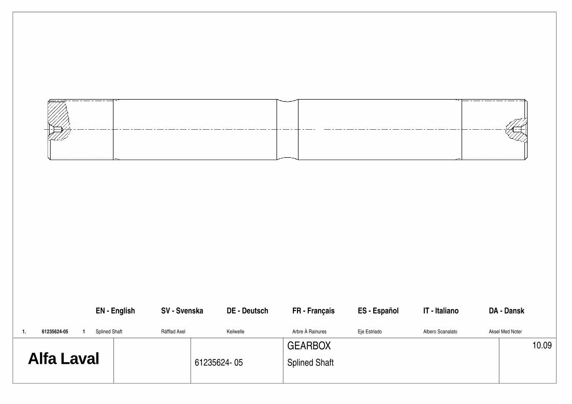
EN - English SV - Svenska DE - Deutsch FR - Français ES - Español IT - Italiano DA - Dansk
1. 61235624-05 1 Splined Shaft Räfflad Axel Keilwelle Arbre À Rainures Eje Estriado Albero Scanalato Aksel Med Noter
Alfa Laval 61235624- 05
GEARBOX
Splined Shaft
10.09


10.09
Alfa Laval 61242887
BACK DRIVE
Back Drive

IT - Italiano DA - Dansk
AZIONAMENTO DEL PIGNONE CENTRALE
SOLHJULSDRIFT
Spessore JustérskiveSpessore JustérskiveSpessore JustérskiveSpessore JustérskiveSpessore JustérskiveMotore MotorVite SkrueAmmortizzatore VibrationsdæmperVite SkrueRondella UnderlagsskiveDado MøtrikLastra PladeVite SkrueRondella Underlagsskive
LEX: Accoppiamento CENAFLEX: CENTAFLEX-kobling:
Mozzo NavMozzo NavElemento di gomma dell’accoppiamento
Gummielement til kobling
Tubo RørFlangia FlangeSpina StiftAnello Ring
Braccio di reazione MomentarmMensola KonsolVite SkrueVite Skrue
Mensola KonsolVite SkrueBussola BøsningMensola KonsolVite SkrueVite SkrueChiavetta FederIndicatore Skilt
10.09
EN - English SV - Svenska DE - Deutsch FR - Français ES - Español
Pos. 61242887-82 Qty BACKDRIVE SOLHJULSDRIFT (BACKDRIVNING)
SONNENRADANTRIEB RETRO-ENTRAINEMENT REDUCTOR DE VELOCIDAD
61241442-11 4 Shim Justeringsbricka Justierscheibe Rondelle d’adjustage Arandela de ajuste61241442-12 4 Shim Justeringsbricka Justierscheibe Rondelle d’adjustage Arandela de ajuste61241442-13 4 Shim Justeringsbricka Justierscheibe Rondelle d’adjustage Arandela de ajuste61241442-14 4 Shim Justeringsbricka Justierscheibe Rondelle d’adjustage Arandela de ajuste61241442-15 4 Shim Justeringsbricka Justierscheibe Rondelle d’adjustage Arandela de ajuste
1 61195635-50 1 Motor Motor Motor Moteur Motor2 61194021-38 4 Screw Skruv Schraube Vis Tornillo4 61204028-16 4 Vibration damper Vibrationsdämpare Schwingungsdämpfer Amortisseur vibrations Amortiguador5 61194021-33 8 Screw Skruv Schraube Vis Tornillo6 61194403-10 8 Washer Bricka Scheibe Rondelle Arandela7 61194301-15 8 Nut Mutter Mutter Ecrou Tuerca8 61242821-80 1 Plate Plåt Blech Plaque Placa9 61194021-64 8 Screw Skruv Schraube Vis Tornillo
10 61194403-12 8 Washer Bricka Scheibe Rondelle Arandela
11 61240578-27 1 CENTAFLEX coupling: CENTAFLEX koppling: CENTAFLEX-Kupplung: Accouplement CENAFLEX: Acoplamiento CENAF
31 61241203-67 1 Hub Nav Nabe Moyau Maza32 61241203-58 1 Hub Nav Nabe Moyau Maza33 61237282-02 2 Rubber element, coupling Gummielement för koppling Gummielement für Kupplung Corpse en caoutchouc de
l’accouplementElemento de goma del acoplamiento
34 61241591-03 1 Tube Rör Rohr Tuyau Tubo35 61240578-05 2 Flange Fläns Flansch Bride Brida36 61241203-95 6 Pin Pinne Stift Goupille Pasador37 61240578-02 2 Ring Ring Ring Anneau Anillo
12 61243460-01 1 Torque arm Momentarm Drehmomentenarm Bras de couple Brazo de torsión13 61242802-01 1 Bracket Konsol Träger Console Ménsula14 61194020-85 2 Screw Skruv Schraube Vis Tornillo15 61194055-73 2 Screw Skruv Schraube Vis Tornillo16 61211273-40 1 Load cell al controls17 61242801-01 1 Bracket Konsol Träger Console Ménsula18 61194021-11 2 Screw Skruv Schraube Vis Tornillo19 61234160-01 2 Bushing Bussning Buchse Douille Casquillo20 61242800-01 1 Bracket Konsol Träger Console Ménsula21 61194080-68 1 Screw Skruv Schraube Vis Tornillo22 61194080-68 1 Screw Skruv Schraube Vis Tornillo23 61233488-09 1 Parallel key Plankil Flachkeil Clavette Chaveta24 61233733-02 1 Sign Skylt Schild Etiquette Letrero
Alfa Laval 61242887- 82
BACK DRIVE
Back Drive

10.09
Alfa Laval 61241363
FRAME AND CASING
Wear Liner

IT - Italiano DA - Dansk
TE RIPARO RESISTENTE ALL’USURA
SLIDFORING
Riparo resistente all’usura Slidforing
Vite Skrue
10.09
EN - English SV - Svenska DE - Deutsch FR - Français ES - Español
Pos. 61241363-80 Qty WEAR LINER SLITFODER VERSCHLEIßBLECH GARDE-BOUE FORRO ANTI-DESGAS
1. 61241364-01 1 Wear liner Slitfoder Verschleißblech Garde-boue Forro anti-desgaste
2. 61194021-04 4 Screw Skruv Schraube Vis Tornillo
Alfa Laval 61241363- 80
FRAME AND CASING
Wear Liner

10.09
Alfa Laval 61240411
FRAME AND CASING
Cover Switch

IT - Italiano DA - Dansk
PA INTERRUTTORE DI COPERCHIO
LÅGKONTAKT
Interruttore di coperchio Lågkontakt
Actuator Actuator
Vite Skrue
Rondella Underlagsskive
Cavo Kabel
10.09
EN - English SV - Svenska DE - Deutsch FR - Français ES - Español
Pos. 61240411-80 Qty COVER SWITCH LOCKAVBRYTARE DECKELSCHALTER INTERRUPTEUR, COUVERCLE
INTERRUPTOR DE TA
1. 61211273-50 1 Cover Switch Lockavbrytare Deckelschalter Interrupteur, couvercle Interruptor de tapa
1 61211273-51 1 Actuator Actuator Actuator Actuator Actuator
5 61194068-20 4 Screw Skruv Schraube Vis Tornillo
6 61194406-04 4 Washer Bricka Scheibe Rondelle Arandela
7 61211275-30 1 Cable Kabel Kabel Câble Cable
Alfa Laval 61240411- 80
FRAME AND CASING
Cover Switch

EN - English SV - Svenska DE - Deutsch FR - Français ES - Español IT - Italiano DA - Dansk
*400 61241403-.. Gasket and Seals - see spe-cial section Gaskets/Seals in this catalogue
Tätningar - se specialsek-tion "Gasket/Seals" i detta kataloget
Dichtungen - siehe Sonder-sektion "Gasket/Seals" in diesem Katalog
Joint et bords d’étanchéité - voir section spéciale "Gas-ket/Seals" de ce catalogue
Guarniciones y Retenes - ve sección especial "Gasket/Seals" de este católogo
Guarnizioni e tenute - vedi sezione speziale "Gasket/Seals" di questo catologo
Pakningssæt - se specialaf-snit "Gasket/Seals" i dette katalog
Alfa Laval 61242769
FRAME AND CASING
Cover
10.09


10.09
1
Alfa Laval 61242946FRAME AND CASING
Mounting Parts, Frame

IT - Italiano DA - Dansk
PEZZI DI MONTAGGIO MONTERINGSDELE
Ammortizzatore Vibrationsdæmper
Vite Skrue
Rondella Underlagsskive
Vite Skrue
Dado Møtrik
Vite Skrue
Coperchio Hus
Mensola Konsol
Vite Skrue
Rondella Underlagsskive
Barra Kantskinne
Vite Skrue
Rondella Underlagsskive
Protezione Skærm
Profilo di protezione Beskyttelseskantliste
10.09
a
EN - English SV - Svenska DE - Deutsch FR - Français ES - Español
Pos. 61242946-81 Qty MOUNTING PARTS MONTAGEDELAR MONTAGETEILE PIECES DE MONTAGE PIEZAS DE MONTAJE
1 61207468-01 4 Vibration damper Vibrationsdämpare Schwingungsdämpfer Amortisseur vibrations Amortiguador
2 61194002-23 4 Screw Skruv Schraube Vis Tornillo
3 61194430-16 4 Washer Bricka Scheibe Rondelle Arandela
4 61194021-41 16 Screw Skruv Schraube Vis Tornillo
5 61194310-05 16 Nut Mutter Mutter Ecrou Tuerca
6 61194088-22 4 Screw Skruv Schraube Vis Tornillo
7 61242585-01 2 Housing Hus Gehäuse Boîte Caja
8 61243373-80 2 Bracket Konsol Träger Console Ménsula
9 61194001-15 4 Screw Skruv Schraube Vis Tornillo
10 61194406-10 4 Washer Bricka Scheibe Rondelle Arandela
11 61241622-01 2 Bar Stång Stab Barre Barra
12 61194021-04 3 Screw Skruv Schraube Vis Tornillo
13 61194403-09 3 Washer Bricka Scheibe Rondelle Arandela
14 61241616-01 1 Guard Skydd Schutzkappe Garde Protección
15 61234080-01 1 Protective profile Skyddskantlist Schutzprofilleiste Filet profilé de protection Perfil de protección
Alfa Laval 61242946- 81
FRAME AND CASING
Mounting Parts, Frame

10.09
2
Alfa Laval 61243373FRAME AND CASING
Hinge Bracket

IT - Italiano DA - Dansk
MENSOLA DELLA CIERNIERA
KONSOL FOR HÆNGSEL
Mensola della cierniera Konsol for hængsel
Rondella Underlagsskive
Rondella Underlagsskive
Molla a disco Tallerkenfjeder
Anello elastico di sicurezza SEEGER-springring
Rondella Underlagsskive
Barra Stang
Rondella Underlagsskive
Vite Skrue
Vite Skrue
Spina Stift
Anello elastico di sicurezza SEEGER-springring
Spina Stift
Loctite Loctite
10.09
b
EN - English SV - Svenska DE - Deutsch FR - Français ES - Español
Pos. 61243373-80 Qty HINGE BRACKET GÅNGJÄRNSKONSOL SCHARNIERTRÄGER CONSOLE DE CHARNIÈRE MÉNSULA DE LA CHARNELA
1 61242569-01 1 Hinge bracket Gångjärnskonsol Scharnierträger Console de charnière Ménsula de la charnela
2 61242539-02 1 Washer Bricka Scheibe Rondelle Arandela
3 61242572-01 1 Washer Bricka Scheibe Rondelle Arandela
4 61242538-02 44 Disc spring Skivfjäder Tellerfeder Ressort à disque Resorte de disco
5 61194470-54 2 Circlip SEEGER fjäderring Seeger-Sicherung (Sprengring)
Sûreté Seeger(Circlip)
Anilla elástica Seeger
6 61242573-01 1 Washer Bricka Scheibe Rondelle Arandela
7 61242574-01 1 Bar Stång Stab Barre Barra
8 61194434-24 1 Washer Bricka Scheibe Rondelle Arandela
9 61194021-60 1 Screw Skruv Schraube Vis Tornillo
10 61194021-08 4 Screw Skruv Schraube Vis Tornillo
11 61242541-01 1 Pin Pinne Stift Goupille Pasador
12 61194452-09 2 Circlip SEEGER fjäderring Seeger-Sicherung (Sprengring)
Sûreté Seeger (Circlip) Anilla elástica Seeger
13 61242541-02 1 Pin Pinne Stift Goupille Pasador
50 00534197-30 1 Loctite Loctite Loctite Loctite Loctite
Alfa Laval 61243373- 80
FRAME AND CASING
Hinge Bracket

e
10.09
Alfa Laval 61242836
FRAME AND CASING
Outlet funnels / Adapter Complet

IT - Italiano DA - Dansk
RGA IMBUTI DI SCARICO UDLØBSTRAGTE
Uscita per concentrato Centratafgang
Guarnizione Pakning
Vite Skrue
10.09
EN - English SV - Svenska DE - Deutsch FR - Français ES - Español
Pos. 61242836-80 Qty OUTLET FUNNELS UTLOPPSTRATTAR ABLASSTRICHTER ENTONNOIRS DE DECHARGE
EMBUDOS DE DESCA
1. 61241406-01 1 Centrate outlet Centratutlopp Konzentratablaß Sortie pour concentré Salida para concentrado
3. 61241407-01 1 Gasket Tätning Dichtung Joint Guarnición
5. 61194069-10 18 Screw Skruv Schraube Vis Tornillo
Alfa Laval 61242836- 80
FRAME AND CASING
Outlet funnels

e
10.09
Alfa Laval 61242836
FRAME AND CASING
Outlet funnels / Adapter Complet

IT - Italiano DA - Dansk
ADATTATORE ADAPTER
Adattatore Adapter
Guarnizione Pakning
Vite Skrue
10.09
EN - English SV - Svenska DE - Deutsch FR - Français ES - Español
Pos. 61242836-81 Qty ADAPTER ADAPTER ADAPTER ADAPTATEUR ADAPTADOR
2. 61241408-01 1 Adapter Adapter Adapter Adaptateur Adaptador
4. 61241409-01 1 Gasket Tätning Dichtung Joint Guarnición
5. 61194069-10 20 Screw Skruv Schraube Vis Tornillo
Alfa Laval 61242836- 81
FRAME AND CASING
Adapter Complete

10.09
Alfa Laval 61241391
MAIN DRIVE
Drive Parts

IT - Italiano DA - Dansk
IPAL TRASMISSIONE PRINCIPALE
HOVEDDRIFT
Coperchio Dæksel
Puleggia per cinghia V Kileremskive
Bussola “Taper-lock” ”Taper-lock”-bøsning
Cinghia trapezoidale Kilerem
Ammortizzatore Vibrationsdæmper
Dado Møtrik
Vite Skrue
Barra filettata Gevindstang
Vite Skrue
Piastra per il montaggio del motore
Motorplade
Rondella Underlagsskive
Dado Møtrik
Rondella Underlagsskive
Vite Skrue
Rondella Underlagsskive
Rondella Underlagsskive
Vite Skrue
Vite Skrue
Rondella Underlagsskive
Dado Møtrik
10.09
EN - English SV - Svenska DE - Deutsch FR - Français ES - Español
Pos. 61241391-20 MAIN DRIVE HUVUDDREV HAUPTANTRIEB TRANSMISSION PRINCIPALE
TRANSMISION PRINC
61236141-80 1 Cover Lock Deckel Couvercle Tapa
1 61233933-07 1 V-belt pulley Kilremskiva Keilriemenscheibe Poulie à courroie V Polea de correa en V
2 61207229-10 1 Taper lock ”Taper-lock” bussning ”Taper-lock”-Buchse Douille “Taper-lock” Cascquillo “Taper-lock”
3 61233967-22 5 V-belt Kilrem Keilriemen Courroie trapézoïdale Correa trapezoidal
5 61204028-11 4 Vibration damper Vibrationsdämpare Schwingungsdämpfer Amortisseur vibrations Amortiguador
6 61194301-17 6 Nut Mutter Mutter Ecrou Tuerca
7 61194021-10 8 Screw Skruv Schraube Vis Tornillo
8 61234112-03 2 Threaded rod Gängad stång Gewindestange Barre taraudée Barra roscada
9 61194021-68 2 Screw Skruv Schraube Vis Tornillo
10 61240148-80 1 Motor plate Fästplåt för motor Befestigungsplatte für Motor Plaque pour montage du moteur
Placa para montaje del motor
11 61194406-10 16 Washer Bricka Scheibe Rondelle Arandela
12 61194301-14 8 Nut Mutter Mutter Ecrou Tuerca
13 61234036-02 4 Washer Bricka Scheibe Rondelle Arandela
14 61194002-23 2 Screw Skruv Schraube Vis Tornillo
15 61194403-12 6 Washer Bricka Scheibe Rondelle Arandela
16 61194406-16 2 Washer Bricka Scheibe Rondelle Arandela
17 61194002-21 2 Screw Skruv Schraube Vis Tornillo
18 61208644-81 2 Screw Skruv Schraube Vis Tornillo
19 61194400-14 4 Washer Bricka Scheibe Rondelle Arandela
20 61194301-19 4 Nut Mutter Mutter Ecrou Tuerca
Alfa Laval 61241391- 20
MAIN DRIVE 60 HZ
Drive Parts

EN - English SV - Svenska DE - Deutsch FR - Français ES - Español IT - Italiano DA - Dansk
6121.0791-01 1 Belt tension tester, type 1 Remspänningsprovare, typ 1 Riemenspannungsprüfgerät, Typ 1
Outil de réglage de la tension des courroies, type 1
Tensor de correas, tipo 1 Tester della tensione delle cinghie, tipo 1
Remspændingstester, type 1
6121.0791-02 1 Belt tension tester, type 2 Remspänningsprovare, typ 2 Riemenspannungsprüfgerät, Typ 2
Outil de réglage de la tension des courroies, type 2
Tensor de correas, tipo 2 Tester della tensione delle cinghie, tipo 2
Remspændingstester, type 2
Alfa Laval 61210791- ..
MAIN DRIVE
Belt Tension Tester
10.09


10.09
Alfa Laval 61243138
ELECTRICAL EQUIPMENT
Electrical Unit

IT - Italiano DA - Dansk
UNITÀ ELETTRICA EL-ENHED
Scatola terminale El-klemkasse
Sensore Føler
Vite Skrue
Rondella Underlagsskive
Mensola Konsol
Sostegno Holder
Vite Skrue
Rondella Underlagsskive
Rondella Underlagsskive
Dado Møtrik
Mensola Konsol
Vite Skrue
Rondella Underlagsskive
Entrata per cavi Kabelforskruning(gennemføring)
Rondella Underlagsskive
Anello Ring
Sensore Føler
Cavo Kabel
Cavo Kabel
Elemento di gomma Gummielement
Rondella Underlagsskive
Dado Møtrik
Vite Skrue
Vite Skrue
Interruttore Kontakt
Filtro Filter
Cavo Kabel
Cavo Kabel
10.09
EN - English SV - Svenska DE - Deutsch FR - Français ES - Español
Pos. 61243138-83 Qty ELECTRICAL UNIT ELEKTRISK ENHET ELEKTRISCHES GERÄT UNITÉ ÉLECTRIQUE UNIDAD ELÉCTRICA
1 61211302-80 1 Junction box Kopplingsdosa Abzweigdose Boîte de branchement Caja de connexiones
3 61211273-30 2 Sensor Avkännare Fühler Détecteur Sensor
7 61194020-81 2 Screw Skruv Schraube Vis Tornillo
8 61194403-08 2 Washer Bricka Scheibe Rondelle Arandela
9 61243139-01 1 Bracket Konsol Träger Console Ménsula
10 61239951-03 1 Holder Hållare Halter Retenue Sostén
11 61194021-07 2 Screw Skruv Schraube Vis Tornillo
12 61194403-09 2 Washer Bricka Scheibe Rondelle Arandela
15 61194400-08 4 Washer Bricka Scheibe Rondelle Arandela
16 61194301-13 4 Nut Mutter Mutter Ecrou Tuerca
17 61242731-01 1 Bracket Konsol Träger Console Ménsula
18 61194099-17 4 Screw Skruv Schraube Vis Tornillo
19 61194406-10 4 Washer Bricka Scheibe Rondelle Arandela
21 61194862-12 4 Cable entry gland Packbox för kabelinföring Kabeleinführung Entrée de câble Entrada para cables
22 61194406-08 4 Washer Bricka Scheibe Rondelle Arandela
25 61243575-01 4 Ring Ring Ring Anneau Anillo
30 61211273-70 2 Sensor Avkännare Fühler Détecteur Sensor
31 61211275-05 1 Cable 5m Kabel Kabel Câble Cable
32 61211275-02 1 Cable 2m Kabel Kabel Câble Cable
33 61243388-01 4 Rubber element Gummielement Gummielement Corpse en caoutchouc Elemento de goma
51 61194403-09 6 Washer Bricka Scheibe Rondelle Arandela
52 61194301-14 6 Nut Mutter Mutter Ecrou Tuerca
53 61194021-04 2 Screw Skruv Schraube Vis Tornillo
54 61194021-10 1 Screw Skruv Schraube Vis Tornillo
90 61211273-20 2 Switch Brytare Schalter Interrupteur Interruptor
91 61243756-01 2 Filter Filter Filter Filtre Filtro
92 61211275-15 1 Cable 5m Kabel Kabel Câble Cable
93 61211275-12 1 Cable 2m Kabel Kabel Câble Cable
Alfa Laval 61243138- 83
ELECTRICAL EQUIPMENT
Electrical Unit

ERED SEPARATELY:
te, for Cover
te, for Frame
10.09
Alfa Laval 61237159
SPECIAL TOOLS TO BE ORD
61237159- .. Lifting Sling, comple
61237159- .. Lifting Sling, comple

ol IT - Italiano DA - Dansk
ESPE-STRAR PECIAL
UTENSILI SPECIALI DA FORNIRE SU ORDINAZI-ONE SPECIALE
SPECIALVÆRKTØJ, SOM LEVERES PÅ SÆRSKILT BESTILLING
a de la Imbragatura di solleva-mento del coperchio
Løftestrop til låg
a del Imbragatura di solleva-mento del fusto
Løftestrop til stativ
RED SEPARATELY:
e, for Cover
e, for Frame
10.09
EN - English SV - Svenska DE - Deutsch FR - Français ES - Españ
Pos. SPECIAL TOOLS TO BE ORDERED SEPARATELY
SPECIALVERKTYG SOM LEVERERAS PÅ SÄR-SKILD BESTÄLLNING
AUF SONDERBESTEL-LUNG ZU LIEFERNDE SPEZIALWERKZEUGE
OUTILS SPECIAUX A FOURNIR SOUS ORDRE SPECIAL
HERRAMIENTASCIALES A SUMINSEGUN PEDIO S
1. 61237159-.. 1 Lifting sling for cover Lyftslinga för lock Hebestropp für Deckel Elingue de levage du couvercle
Eslinga elevadortapa
-85 NX928 / NX930
-86 NX934 / NX935
-87 NX936 / NX937 / NX944 / NX945
-88 NX946 / NX947
-92 NX706 / NX707/ NX6540/ NX7240
-98 NX5152
-77 NX3650
2. 61237159-.. 1 Lifting sling for frame Lyftslinga för stativ Hebestropp für Gestell Elingue de levage du bâti Eslinga elevadorarmazón
-80 NX414 / NX417
-81 NX416 / NX419 / NX928 / NX930
-82 NX418 / NX420 / NX934 / NX935 / NX936 / NX937
-90 NX422
-83 NX438
-84 NX944 / NX945
-89 NX946 / NX947
-91 NX706 / NX707
-93 NX441
-94 NX904
-95 LYNX 20 BACKDRIVE
-96 NX912 / NX913
-97 NX910 / NX911
-99 NX5152
-79 NX6540
-78 NX3650
-76 NX7240
-75 LYNX60
Alfa Laval 61237159- ..
SPECIAL TOOLS TO BE ORDE
61237159- .. Lifting Sling, complet
61237159- .. Lifting Sling, complet

10.09
Alfa Laval 61241375
SPECIAL TOOLS
Special Tools

IT - Italiano DA - Dansk
UTENSILI SPECIALI SPECIALVÆRKTØJ
Estrattore Aftrækker
Disco estrattore Aftrækkerskive
Disco estrattore Aftrækkerskive
Disco estrattore Aftrækkerskive
Vite Skrue
Vite Skrue
Chiave essagonale Unbrakonøgle (inseksnøgle)
Anello estrattore Aftrækkerring
Barra filettata Gevindstang
Bussola Bøsning
Barra filettata Gevindstang
Bussola Bøsning
Dado ad occhio Løfteøje
Vite Skrue
Chiave a gancio Hagenøgle
Imbragatura di sollevamento Løftestrop
de Estrattore di manicotti spinati Afrækker forstyrestiftbøsning
Vite Skrue
Disco estrattore Aftrækkerskive
Spina guida Styrestift
Dado Møtrik
Estrattore Aftrækker
Dado Møtrik
Vite Skrue
10.09
EN - English SV - Svenska DE - Deutsch FR - Français ES - Español
Pos. 61241375-80 Qty SPECIAL TOOLS SPECIALVERKTYG SPEZIAL-WERKZEUGE OUTILS SPECIAUX HERRAMIENTAS ESPECIALES
1. 61241368-80 1 Puller Avdragare Abziehwerkzeug Extracteur Extractor
2. 61241302-01 1 Thrust plate Avdragningsskiva Abziehscheibe Disque arracheur Disco extractor
3. 61241559-01 1 Thrust plate Avdragningsskiva Abziehscheibe Disque arracheur Disco extractor
4. 61241372-01 1 Thrust plate Avdragningsskiva Abziehscheibe Disque arracheur Disco extractor
5. 61194069-14 4 Screw Skruv Schraube Vis Tornillo
6. 61194051-12 4 Screw Skruv Schraube Vis Tornillo
7. 61194901-40 1 Allen key Sexkanthålnyckel Sechskantstiftschlüssel Clé hexagonale Llave hexagonal
8. 61241385-01 1 Puller ring Avdragningsring Abziehring Anneau extracteur Anillo extractor
9. 61241712-01 4 Threaded rod Gängad stång Gewindestange Barre taraudée Barra roscada
10. 61241434-01 1 Bushing Bussning Buchse Douille Casquillo
11. 61241714-01 1 Threaded rod Gängad stång Gewindestange Barre taraudée Barra roscada
12. 61240094-80 1 Bushing Bussning Buchse Douille Casquillo
13. 61239863-80 1 Eye nut Ringmutter Augenmutter Ecrou à oeillet Tuerca de ojo
14. 61194025-67 2 Screw Skruv Schraube Vis Tornillo
15. 61211062-02 1 Hook spanner Haknyckel Hakenschlüssel Clé à crochet Llave de gancho
16. 61233785-01 1 Lifting sling Lyftslinga Hebestropp Elingue de levage Eslinga elevadora
17. 61233781-80 1 Dowel sleeve extractor Avdragare för styrstifthylsa Paßstifhülsen-Abziehwerk-zeug
Outil extracteur du machon de goupille
Extractor del casquillo pasador
18. 61194051-11 2 Screw Skruv Schraube Vis Tornillo
19. 61241702-01 1 Thrust plate Avdragningsskiva Abziehscheibe Disque arracheur Disco extractor
20. 61241619-01 1 Guide pin Styrstift Führungsstift Goupille de guidage Pasador de guía
21. 61194300-10 4 Nut Mutter Mutter Ecrou Tuerca
22 61212652-01 1 Puller Avdragare Abziehwerkzeug Extracteur Extractor
23. 61234110-01 1 Nut Mutter Mutter Ecrou Tuerca
24. 61194051-13 4 Screw Skruv Schraube Vis Tornillo
Alfa Laval 61241375- 80
SPECIAL TOOLS
Special Tools

10.09
Alfa Laval 61206643
TOOLS
Universal Tools

IT - Italiano DA - Dansk
UTENSILI UNIVERSALI UNIVERSALVÆRKTØJ
Cacciavite Skruetrækker
Cacciavite Skruetrækker
Martello Hammer
nales Serie di chiavi essagonali Sæt inseksnøgler
ales Serie di chiavi universali Ring-gaffelnøgle, sæt
Chiave universale Ring- / gaffelnøgle
Chiave universale Ring- / gaffelnøgle
Pinze per Anelli elastici di sicurezza
Seegerringstang
Pinze per Anelli elastici di sicurezza
Seegerringstang
Pinze per Anelli elastici di sicurezza
Seegerringstang
Pinze per Anelli elastici di sicurezza
Seegerringstang
Pinze per Anelli elastici di sicurezza
Seegerringstang
Pinze per Anelli elastici di sicurezza
Seegerringstang
10.09
EN - English SV - Svenska DE - Deutsch FR - Français ES - Español
Pos. 61206643-81 UNIVERSAL TOOLS UNIVERSALVERKTYG UNIVERSAL-WERKZEUGE OUTILS UNIVERSELS HERRAMIENTASUNIVERSALES
1. 61194906-00 1 Screw driver Skruvmejsel Schraubenzieher Tournevis Destornillador
2. 61194906-01 1 Screw driver Skruvmejsel Schraubenzieher Tournevis Destornillador
3. 61160115-80 1 Hammer Hammare Hammer Marteau Martillo
4. 61194901-40 1 Set of hexagon keys Sats sexkanthålnycklar Satz Sechskantstiftschlüssel Jeu de clées hexagonales Juego de llaves hexago
5. 61194910-40 1 Set of combination wrenches Sats ring- och fastnycklar Satz Universalschlüssel Jeu des clés universelles Juego de llaves univers
5. 61194910-24 1 Combination wrench Ring- och fastnyckel Universalschlüssel Clé universelle Llave universal
5. 61194910-29 1 Combination wrench Ring- och fastnyckel Universalschlüssel Clé universelle Llave universal
6. 61194930-01 1 Circlip pliers Tång för SEEGERfjäderringar
Zange für Sprengringe Pinces pour circlips Tenazas para Anillos elásticos Seeger
7. 61194930-02 1 Circlip pliers Tång för SEEGERfjäderringar
Zange für Sprengringe Pinces pour circlips Tenazas para Anillos elásticos Seeger
8. 61194930-03 1 Circlip pliers Tång för SEEGERfjäderringar
Zange für Sprengringe Pinces pour circlips Tenazas para Anilloselásticos Seeger
9. 61194932-02 1 Circlip pliers Tång för SEEGERfjäderringar
Zange für Sprengringe Pinces pour circlips Tenazas para Anilloselásticos Seeger
10. 61194932-03 1 Circlip pliers Tång för SEEGERfjäderringar
Zange für Sprengringe Pinces pour circlips Tenazas para Anilloselásticos Seeger
11. 61194932-04 1 Circlip pliers Tång för SEEGERfjäderringar
Zange für Sprengringe Pinces pour circlips Tenazas para Anilloselásticos Seeger
Alfa Laval 61206643- 81
TOOLS
Universal Tools

10.09
Alfa Laval 61241417
SPECIAL TOOLS
Lifting Tool for Bowl

IT - Italiano DA - Dansk
IMBRAGATURA DI SOLLEVAMENTO PER TAMBURO
LØFTESTROP TIL KUGLE
Imbragatura di sollevamento Løftestrop
Barra Kantskinne
Barra Kantskinne
Vite Skrue
Targa d'avviso Advarselsskilt
10.09
EN - English SV - Svenska DE - Deutsch FR - Français ES - Español
Pos. 61241417-80 Qty LIFTING SLING FOR BOWL LYFTSLINGA FÖR TRUMMA
HEBESTROPP FÜR TROMMEL
ELINGUE DE LEVAGE POUR TAMBOUR
ESLINGA ELEVADORAPARA ROTOR
1 61243319-01 1 Lifting sling Lyftslinga Hebestropp Elingue de levage Eslinga elevadora
2 61243320-01 2 Bar Stång Stab Barre Barra
3 61243321-01 4 Bar Stång Stab Barre Barra
4 61194051-39 4 Screw Skruv Schraube Vis Tornillo
5 61243605-01 1 Warning sign Varningsskylt Warnungstafel Tableau d'avertissement Letrero de aviso
Alfa Laval 61241417-80
SPECIAL TOOLS
Lifting Sling for Bowl

10.09
Alfa Laval 61243598
SPECIAL TOOLS
Lifting Tool for Conveyor

IT - Italiano DA - Dansk
UTENSILE DI SOLLEVAMENTO PER COCLEA
LØFTEVÆRKTØJ TIL TRANSPORTØR
Utensile di sollevamento Løfteværktøj
Anello di trazione Sjækkel
Indicatore Skilt
ar- Vite autofilettante Drivskrue / Drivnagle
Indicatore Skilt
Vite Skrue
Rondella Underlagsskive
Indicatore Skilt
10.09
EN - English SV - Svenska DE - Deutsch FR - Français ES - Español
Pos. 61243598-80 Qty LIFTING TOOL FOR CONVEYOR
LYFTVERKTYG FÖR TRANSPORTÖR
HEBEVORRICHTUNG FÜR FÖRDERSCHNECKE
OUTIL DE LEVAGE POUR VIS TRANSPORTEUSE
HERRAMIENTA ELEVADORA PARA TORNILLO TRANSPORTADOR
1. 61243599-80 1 Lifting tool Lyftverktyg Hebevorrichtung Outil de levage Herramienta elevadora
2. 61210727-01 1 Shackle Schackel Schäkel Maillon d’attache Grillete
3. 61233788-01 1 Sign Skylt Schild Etiquette Letrero
4. 61234107-01 4 Drive screw Slagskruv Einschlagschraube Vis de battage Tornillo hundido con el mtillo
5. 61211049-03 1 Sign Skylt Schild Etiquette Letrero
6. 61194051-21 7 Screw Skruv Schraube Vis Tornillo
7. 61194403-09 7 Washer Bricka Scheibe Rondelle Arandela
8. 61241592-01 1 Sign Skylt Schild Etiquette Letrero
Alfa Laval 61243598- 80
SPECIAL TOOLS
Lifting Tool for Conveyor

10.09
Alfa Laval 61241281
ACCESSORIES
Gearbox, Service Kit

IT - Italiano DA - Dansk
S O
SERIE DI PEZZI DI RICAMBIO PER MANUTENZIONE
SERVICE-KIT
Bussola Monteringsbøsning
Bussola Monteringsbøsning
Tenuta a labbro Læbetætning
Anello O-R O-ring
10.09
EN - English SV - Svenska DE - Deutsch FR - Français ES - Español
Pos. 61241281-10 Qty SERVICE KIT SATS RESERVDELAR FÖR SERVICE
ERSATZTELLSATZ FÜR WARTUNG
JEU DE PIECES DE RECHANGE POUR ENTRETIEN
JUEGO DE REPUESTOPARA MANTENIMIENT
61241446-02 1 Mounting bushing Bussning Buchse Douille Casquillo
61241446-02 1 Mounting bushing Bussning Buchse Douille Casquillo
33. 61234187-03 1 Lip seal Läpptätning Lippendichtung Joint à lèvre Junta
59. 61167213-54 1 O-ring O-ring O-Ring Anneau O Junta tórica
Alfa Laval 61241281- 10
ACCESSORIES
Gearbox, Service Kit

n
10.09
Alfa Laval 61211050
ACCESSORIES
Lubricants and Tools for Operatio

IT - Italiano DA - Dansk
UTENSILI DI ESERCIZIO BETJENINGSVÆRKTØJ
Chiave a gancio Hagen¢gle
de Estrattore di manicotti spinati Afrækker forstyrestiftb¢sning
10.09
EN - English SV - Svenska DE - Deutsch FR - Français ES - Español
Pos. 61211050-40 TOOLS FOR OPERATION DRIFTSVERKTYG BEDIENUNGSWERKZEUGE OUTILS DE MANOEVRE HERRAMIENTAS DESERVICIO
1. 00073800-00 1 Hook spanner Haknyckel Hakenschlüssel Clé à crochet Llave de gancho
11. 61233781-80 1 Dowel sleeve extractor Avdragare för styrstifthylsa Paßstifhülsen-Abziehwerkzeug
Outil extracteur du machon de goupille
Extractor del casquillo pasador
Alfa Laval 61211050- 40
ACCESSORIES
Tools for Operation

10.09
Alfa Laval 61241403
SEALS AND GASKETS
Seals and Gaskets
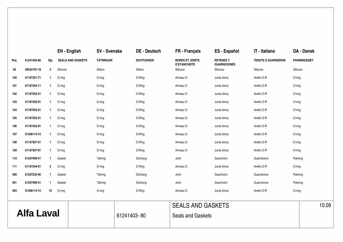
IT - Italiano DA - Dansk
TENUTE E GUARNIZIONI PAKNINGSSÆT
Silicone Silicone
Anello O-R O-ring
Anello O-R O-ring
Anello O-R O-ring
Anello O-R O-ring
Anello O-R O-ring
Anello O-R O-ring
Anello O-R O-ring
Anello O-R O-ring
Anello O-R O-ring
Anello O-R O-ring
Guarnizione Pakning
Anello O-R O-ring
Guarnizione Pakning
Guarnizione Pakning
Anello O-R O-ring
10.09
EN - English SV - Svenska DE - Deutsch FR - Français ES - Español
Pos. 61241403-80 Qty SEALS AND GASKETS TÄTNINGAR DICHTUNGEN BORDS ET JOINTS D’ETANCHEITE
RETENES Y GUARNICIONES
50 00534197-18 2 Silicone Silikon Silikon Silicone Silicona
100 61167251-71 1 O-ring O-ring O-Ring Anneau O Junta tórica
101 61167244-11 1 O-ring O-ring O-Ring Anneau O Junta tórica
102 61167253-51 1 O-ring O-ring O-Ring Anneau O Junta tórica
103 61167252-91 1 O-ring O-ring O-Ring Anneau O Junta tórica
104 61167253-21 1 O-ring O-ring O-Ring Anneau O Junta tórica
105 61167253-41 1 O-ring O-ring O-Ring Anneau O Junta tórica
106 61167252-81 1 O-ring O-ring O-Ring Anneau O Junta tórica
107 61206114-15 1 O-ring O-ring O-Ring Anneau O Junta tórica
108 61167207-51 1 O-ring O-ring O-Ring Anneau O Junta tórica
109 61167207-91 1 O-ring O-ring O-Ring Anneau O Junta tórica
110 61207599-51 1 Gasket Tätning Dichtung Joint Guarnición
111 61167244-51 2 O-ring O-ring O-Ring Anneau O Junta tórica
400 61237233-46 1 Gasket Tätning Dichtung Joint Guarnición
401 61207599-31 1 Gasket Tätning Dichtung Joint Guarnición
403 61206114-10 10 O-ring O-ring O-Ring Anneau O Junta tórica
Alfa Laval 61241403- 80
SEALS AND GASKETS
Seals and Gaskets

10.09
Alfa Laval 61241419
ACCESSORIES
Signs and Labels

IT - Italiano DA - Dansk
TAS INDICATORI E TARGHETTE
SKILTEENHED
Indicatore Skilt
Targa d'avviso Advarselsskilt
Targa d'avviso Advarselsskilt
Targa d'avviso Advarselsskilt
Indicatore Skilt
Indicatore Skilt
Targa d'avviso Advarselsskilt
Targa d'avviso Advarselsskilt
10.09
EN - English SV - Svenska DE - Deutsch FR - Français ES - Español
Pos. 61241419 SIGNS AND LABELS SKYLTAR OCHETIKETTAR
SCHILDER UND ETIKETTE AVVERTISEMENTS ET ETIQUETTES
LETREROS Y ETIQUE
4. 61204214-01 1 Sign Skylt Schild Etiquette Letrero
6. 61231923-.. 4 Warning sign (board) Varningsskylt Warnungstafel Tableau d'avertissement Letrero de aviso
7. 61425252-01 1 Warning sign (board) Varningsskylt Warnungstafel Tableau d'avertissement Letrero de aviso
8. 61425250-01 1 Warning sign (board) Varningsskylt Warnungstafel Tableau d'avertissement Letrero de aviso
11. 61233942-03 1 Sign Skylt Schild Etiquette Letrero
12. 61233942-02 1 Sign Skylt Schild Etiquette Letrero
13. 61425253-01 8 Warning sign (board) Varningsskylt Warnungstafel Tableau d'avertissement Letrero de aviso
14. 61241640-01 4 Warning sign (board) Varningsskylt Warnungstafel Tableau d'avertissement Letrero de aviso
Alfa Laval 61241419
ACCESSORIES
Signs and Labels


G2-95 CENTRIFUGE FLEXIBLE CONNECTION ELEVATION
TOP VIEW
1
1
2
2
3
3
4
4
5
5
6
6
7
7
8
8
A A
B B
C C
D D
E E
F F
G G
H H
SHEET 1 OF 8
DRAWN
CHECKED
QA
MFG
APPROVED
JHK 10/22/2010
DWG NO
75701
TITLE
G2-95 CENTRIFUGE FLEXIBLE CONNECTIONS
SIZE
ESCALE
REV
2
THIS PRINT REPRESENTS DESIGN AND ENGINEERING EFFORTS OF ALFA LAVAL. IT IS LOANED IN CONFIDENCE AND MUST BE RETURNED ON DEMAND. ANY USE DETERMENTAL TO THE INTERESTS OF ALFA LAVAL INC. IS PROHIBITED. IT MUST NOT BE LOANED, COPIED OR REPRODUCED WITHOUT PERMISSION.
PARTS LISTMATERIALDESCRIPTIONQTYITEM
G2-95 CENTRIFUGE31304SS/EPDMFLEXIBLE FEED HOSE32TEFLON LINED SS BRAIDFLEXIBLE POLYMER CONNECTION63304SS/EPDMCENTRATE FUNNEL WITH FLANGED HOSE34CI NEOPRENE/304SSSOLIDS OUTLET FLEX CONNECTOR 35304SSSOLIDS OUTLET CHUTE 36304SSSOLIDS TAPER CHUTE37
7'-2516" 1'-5"
2
1
THIS DRAWING IS CERTIFIED FOR; CUSTOMER; MWH CONSTRUCTORS, INC. ADDRESS; 3807 SPRINGHILL ROAD TALLAHASSEE, FL. 32305PROJECT; CITY OF TALLAHASSEE, TPS WRF IMPROVMENTS SOLD TO; CITY OF TALLAHASSEE, FLALFA LAVAL ORDER: 395293 CUSTOMER ORDER: P7012396-040 CERTIFIED BY: PAUL RUSSELL DATE: 10/27/10
778"
1'-2116"
3'-458"
3
3
6
5
1 CHANGED DESIGN PER SUBMITTAL COMMENTS 8/13/2010 2 CHANGED PER SUBMITTAL COMMENTS 10/26/2010
REVISION HISTORYREV DESCRIPTION DATE APPROVED
EL = 87.13
EL = 89.30
7
FF EL = 94.50
FF EL = 82.00
10"
12'-6" TYPICAL
3'-81316"
7'-31116"
5'-1916"
1'-9"4'-215
16"9'-9"
9'-101316"
5'-1 4"
2'-0"TYPICAL
4'-61116"
6'-1134"
15°
1'-111116"
4'-314"
10'-7916" 5'-67
16"
16'-2" 14'-2"
F E D
2'-3916"
3'-10316"
1'-418"
1'-7 8" 1'-3316"
4
BOTTOM CHUTE FLANGE ON ITEM # MUST CLEAR FLOOR PENETRATION
O.D. OF 8" HOSE MUST FIT THROUGH FLOOR PENETRATION
1'-618" x 2'-77
8"
n1'-7"
81116"
12" 125# PLATE FLANGECENTRATE DISCHARGE
EL = 92.52
778"
1'-2116"
3'-478"
4'-234"
1'-312"
8'-51316"
7'-2516"
ENTIRE SHEET REVISED 2

FEED CONNECTION - QTY OF 3
1
1
2
2
3
3
4
4
A A
B B
C C
D D
SHEET 2 OF 8
DRAWN
CHECKED
QA
MFG
APPROVED
JHK 10/22/2010
DWG NO
75701
TITLE
G2-95 CENTRIFUGE FLEXIBLE FEED CONNECTION
SIZE
CSCALE
REV
2
THIS PRINT REPRESENTS DESIGN AND ENGINEERING EFFORTS OF ALFA LAVAL. IT IS LOANED IN CONFIDENCE AND MUST BE RETURNED ON DEMAND. ANY USE DETERMENTAL TO THE INTERESTS OF ALFA LAVAL INC. IS PROHIBITED. IT MUST NOT BE LOANED, COPIED OR REPRODUCED WITHOUT PERMISSION.
PARTS LISTMATERIALDESCRIPTIONQTYITEM
4" 150# FF FLANGE GASKET11304SS4" 150# FLANGE12304SS4" TO 2-1/2" REDUCER13316SS2-1/2" KC NIPPLE14EPDM2-1/2" SUCTION/DISCHARGE HOSE15SS2-1/2" T-BOLT CLAMP26 FASTENER LIST 18-8SS5/8 x 2-1/2" HEX HEAD BOLT8718-8SS5/8" HEX NUT88
7 8
212"n
116" 77
8"1'-8"
3 4 5
6 6
4"n
2
1
THIS DRAWING IS CERTIFIED FOR; CUSTOMER; MWH CONSTRUCTORS, INC. ADDRESS; 3807 SPRINGHILL ROAD TALLAHASSEE, FL. 32305PROJECT; CITY OF TALLAHASSEE, TPS WRF IMPROVMENTS SOLD TO; CITY OF TALLAHASSEE, FLALFA LAVAL ORDER: 395293 CUSTOMER ORDER: P7012396-040 CERTIFIED BY: PAUL RUSSELL DATE: 10/27/10

FLEXIBLE POLYMER CONNECTION - QTY OF 6
1
1
2
2
3
3
4
4
A A
B B
C C
D D
SHEET 3 OF 8
DRAWN
CHECKED
QA
MFG
APPROVED
JHK 10/22/2010
DWG NO
75701
TITLE
G2-95 CENTRIFUGE FLEXIBLE POLYMER CONNECTION
SIZE
CSCALE
REV
2
THIS PRINT REPRESENTS DESIGN AND ENGINEERING EFFORTS OF ALFA LAVAL. IT IS LOANED IN CONFIDENCE AND MUST BE RETURNED ON DEMAND. ANY USE DETERMENTAL TO THE INTERESTS OF ALFA LAVAL INC. IS PROHIBITED. IT MUST NOT BE LOANED, COPIED OR REPRODUCED WITHOUT PERMISSION.
PARTS LISTMATERIALDESCRIPTIONQTYITEM
304SS3/4 150# FULL COULING11SS3/4 MNPT CRIMP HOSE FITTING12TEFLON LINED SS BRAIDHOSE 13SS3/4 FEMALE JIC SWIVEL CRIMP FITTING14SS3/4 JIC x 3/4 MNPT ADAPTER15304SS3/4 THREADED FLANGE16NA3/4 FF FLANGE GASKET17 FASTENER LIST 18-8SS1/2 x 1-3/4 HEX HEAD BOLT4818-8SS1/2 HEX NUT49
1'-10"
2'-5 16"
12345
3/4 FNPT
67
89
THIS DRAWING IS CERTIFIED FOR; CUSTOMER; MWH CONSTRUCTORS, INC. ADDRESS; 3807 SPRINGHILL ROAD TALLAHASSEE, FL. 32305PROJECT; CITY OF TALLAHASSEE, TPS WRF IMPROVMENTS SOLD TO; CITY OF TALLAHASSEE, FLALFA LAVAL ORDER: 395293 CUSTOMER ORDER: P7012396-040 CERTIFIED BY: PAUL RUSSELL DATE: 10/27/10

CENTRATE FUNNEL WITH 8" FLANGED HOSE - QTY OF 3
TOP VIEW
SECTION A-A
1
1
2
2
3
3
4
4
A A
B B
C C
D D
SHEET 5 OF 8
DRAWN
CHECKED
QA
MFG
APPROVED
JHK 10/22/2010
DWG NO
75701
TITLE
G2-95 CENTRIFUGE CENTRATE FUNNELWITH 12" 125# FLANGED HOSESIZE
CSCALE
REV
2
THIS PRINT REPRESENTS DESIGN AND ENGINEERING EFFORTS OF ALFA LAVAL. IT IS LOANED IN CONFIDENCE AND MUST BE RETURNED ON DEMAND. ANY USE DETERMENTAL TO THE INTERESTS OF ALFA LAVAL INC. IS PROHIBITED. IT MUST NOT BE LOANED, COPIED OR REPRODUCED WITHOUT PERMISSION.
PARTS LISTMATERIALDESCRIPTIONQTYITEM
CI NEOPRENECENTRATE OUTLET FLANGE GASKET11304SSCENTRATE FUNNEL 11GA PLATE12EPDM8" DISCHARGE HOSE13SS8" T-BOLT CLAMP24304SS12" 125# PLATE FLANGE WITH 8" HOSE RING15CI NEOPRENE12" FF FLANGE GASKET16304SS2 HALF COUPLING17316SS2" THREADED KC NIPPLE28EPDM2" SUCTION DISCHARGE HOSE19SS2" T-BOLT CLAMP210304SS2" 150# THREADED FLANGE111NA2" FF FLANGE GASKET112304SS1/2" THREADED 45Deg ELBOW213304SS1/2" x 3" THREADED NIPPLE214304SS1/2" FULL COUPLING215304SS1/2" SPRAY NOZZLE216 FASTENER LIST 18-8SS10 x 30mm SOCKET HEAD CAP SCREW181718-8SS1/2 x 2-1/4 HEX HEAD BOLT41818-8SS1/2 HEX NUT41918-8SS7/8 x 3 HEX HEAD BOLT122018-8SS7/8 HEX NUT1221
A A
1'-1 8"
1'-418"
4'-3"
14"
2'-818"
FLEXIBILITY
171
2
4
4
5 12"
62021
6316" 63
16"
2'-238"
13
13
16
CENTRATE SAMPLE PORT
1'-4316"
2"
2'-101316"
111'-0"
FLEXIBILITY
n71516"
n1'-7"
n1"
5
8
9
10
10
8
7
15
14
14
3'-278"
2
22
916" 51
8"
1014"
1'-338"
1'-812"
2'-1916"
2'-61116"
4516"
81116"
1'-1"
916"
n716 18X
2
THIS DRAWING IS CERTIFIED FOR; CUSTOMER; MWH CONSTRUCTORS, INC. ADDRESS; 3807 SPRINGHILL ROAD TALLAHASSEE, FL. 32305PROJECT; CITY OF TALLAHASSEE, TPS WRF IMPROVMENTS SOLD TO; CITY OF TALLAHASSEE, FLALFA LAVAL ORDER: 395293 CUSTOMER ORDER: P7012396-040 CERTIFIED BY: PAUL RUSSELL DATE: 10/27/10

SOLIDS OUTLET FLEXIBLE CONNECTION - QTY OF 3
TOP VIEW(TOP & BOTTOM FLANGE PATTERN)
SECTION B-B
1
1
2
2
3
3
4
4
A A
B B
C C
D D
SHEET 6 OF 8
DRAWN
CHECKED
QA
MFG
APPROVED
JHK 10/22/2010
DWG NO
75701
TITLE
G2-95 CENTRIFUGE SOLIDS OUTLET FLEXIBLE CONNECTOR
SIZE
CSCALE
REV
2
THIS PRINT REPRESENTS DESIGN AND ENGINEERING EFFORTS OF ALFA LAVAL. IT IS LOANED IN CONFIDENCE AND MUST BE RETURNED ON DEMAND. ANY USE DETERMENTAL TO THE INTERESTS OF ALFA LAVAL INC. IS PROHIBITED. IT MUST NOT BE LOANED, COPIED OR REPRODUCED WITHOUT PERMISSION.
B
B
PARTS LISTMATERIALDESCRIPTIONQTYITEM
CI NEOPRENESOLIDS OUTLET FLEXIBLE CONNECTOR11304SSSOLIDS OUTLET FLEXIBLE CONNECTOR BACKER BAR22URETHANESOLIDS OUTLET FLEXIBLE CONNECTOR WEAR LINER13 FASTENER LIST 18-8SSM10 x 40mm SOCKET HEAD CAP SCREW20418-8SS3/8 x 1-1/2 HEX HEAD BOLT20518-8SS3/8 FLAT WASHER40618-8SS3/8 NYLOCK HEX NUT207
3
1
2
2
1
2
34
2
5667
916"
414"
812"
1'-1116"
1'-41516"
1'-618"
812"MFG
INSTALLED 8811
16"
316"
14"1
4"
916" 51
8"
1014"
1'-338"
1'-812"
2'-1916"
2'-61116"
2'-778"
2'-412"
1'-278"
n716 20X
THIS DRAWING IS CERTIFIED FOR; CUSTOMER; MWH CONSTRUCTORS, INC. ADDRESS; 3807 SPRINGHILL ROAD TALLAHASSEE, FL. 32305PROJECT; CITY OF TALLAHASSEE, TPS WRF IMPROVMENTS SOLD TO; CITY OF TALLAHASSEE, FLALFA LAVAL ORDER: 395293 CUSTOMER ORDER: P7012396-040 CERTIFIED BY: PAUL RUSSELL DATE: 10/27/10

SOLIDS OUTLET CHUTE - QTY OF 3
END VIEW
TOP VIEW(TOP & BOTTOM FLANGE PATTERN)
1
1
2
2
3
3
4
4
A A
B B
C C
D D
SHEET 7 OF 8
DRAWN
CHECKED
QA
MFG
APPROVED
JHK 10/22/2010
DWG NO
75701
TITLE
G2-95 CENTRIFUGESOLIDS OUTLET CHUTE
SIZE
CSCALE
REV
2
THIS PRINT REPRESENTS DESIGN AND ENGINEERING EFFORTS OF ALFA LAVAL. IT IS LOANED IN CONFIDENCE AND MUST BE RETURNED ON DEMAND. ANY USE DETERMENTAL TO THE INTERESTS OF ALFA LAVAL INC. IS PROHIBITED. IT MUST NOT BE LOANED, COPIED OR REPRODUCED WITHOUT PERMISSION.
PARTS LISTMATERIALDESCRIPTIONQTYITEM
304SSSOLIDS OUTLET CHUTE 3/16" PLATE11304SSSOLIDS CHUTE SUPPORT FRAME12304SS2" HALF COUPLING13304SS2" SQ HEAD PLUG14304SS1/2" THREADED 45Deg ELBOW25304SS1/2" x 3" THREADED NIPPLE26304SS1/2" FULL COUPLING27304SS1/2" FLUSH NOZZLE28CI NEOPRENESOLIDS OUTLET FLANGE GASKET19 FASTENER LIST 18-8SS3/8" x 1-1/2" HEX HEAD BOLT201018-8SS3/8" FLAT WASHER401118-8SS3/8" NYLOCK HEX NUT2012
916"
414"
812"
1'-1116"
1'-41516"
916" 51
8"
1014"
1'-338"
1'-812"
2'-1916"
2'-61116"
2'-778"
1'-618"
3"
3"
6"
1'-678"
2'-11"
14"
1'-5" 1'-5"
SAMPLE PORT
4
5
9
1
10 11 11 12
4
3
5
6
5
6
7
8
7
8
4
5
5
n716 20X
ENTIRE SHEET REVISED
2" SQ.TYPICAL
22
n1116 FLOOR
MOUNTING HOLES 4X
1'-834" 1'-83
4"
3'-912"
81516" 815
16"
1'-778"
n1116 FLOOR
MOUNTING HOLES 4X
2
THIS DRAWING IS CERTIFIED FOR; CUSTOMER; MWH CONSTRUCTORS, INC. ADDRESS; 3807 SPRINGHILL ROAD TALLAHASSEE, FL. 32305PROJECT; CITY OF TALLAHASSEE, TPS WRF IMPROVMENTS SOLD TO; CITY OF TALLAHASSEE, FLALFA LAVAL ORDER: 395293 CUSTOMER ORDER: P7012396-040 CERTIFIED BY: PAUL RUSSELL DATE: 10/27/10

SECTION C-C
SECTION D-D
1
1
2
2
3
3
4
4
A A
B B
C C
D D
SHEET 8 OF 8
DRAWN
CHECKED
QA
MFG
APPROVED
JHK 10/22/2010
DWG NO
75701
TITLE
G2-95 CENTRIFUGESOLIDS OUTLET TAPER CHUTE
SIZE
CSCALE
REV
2
THIS PRINT REPRESENTS DESIGN AND ENGINEERING EFFORTS OF ALFA LAVAL. IT IS LOANED IN CONFIDENCE AND MUST BE RETURNED ON DEMAND. ANY USE DETERMENTAL TO THE INTERESTS OF ALFA LAVAL INC. IS PROHIBITED. IT MUST NOT BE LOANED, COPIED OR REPRODUCED WITHOUT PERMISSION.
C C
D D
PARTS LISTMATERIALDESCRIPTIONQTYITEM
304SSSOLIDS OUTLET TAPER CHUTE11CI NEOPRENEAUGER INLET FLANGE GASKET12 FASTENER LIST 18-8SS3/8 x 1 1/2 HEX HEAD BOLT14318-8SS3/8 FLAT WASHER28418-8SS3/8 NYLON INSERT HEX NUT145
916"
414"
8716"
1'-1116"
1'-41516"
916" 51
8"
1014"
1'-338"
1'-812"
2'-1916"
2'-61116"
n716 20X
78" 51
8"
1038"
1'-312"
78"
518"
1014"
1'-338"
1'-812"
n716 14X
23445
2
2
NEW SHEET
THIS DRAWING IS CERTIFIED FOR; CUSTOMER; MWH CONSTRUCTORS, INC. ADDRESS; 3807 SPRINGHILL ROAD TALLAHASSEE, FL. 32305PROJECT; CITY OF TALLAHASSEE, TPS WRF IMPROVMENTS SOLD TO; CITY OF TALLAHASSEE, FLALFA LAVAL ORDER: 395293 CUSTOMER ORDER: P7012396-040 CERTIFIED BY: PAUL RUSSELL DATE: 10/27/10
2
3'-91116"
14"
3'-91516"

Tab 5
Centrifuge Accessory Cut Sheets


Rev 2010
OPERATOR'S TROUBLESHOOTING GUIDE
INDICATION CAUSE REMEDY
Typical, no action needed. Machine Vibrates 1. Moderate vibrations
normally occur at the critical
nubmer of revolutions during
the runup and the shutdown
periods
If the vibrations seem
excessive on shutdown,
evaluate and adjust flushing
water to proper amount (note:
flush water should be
introduced until 300‐500 rpm
periods.
introduced until 300 500 rpm
on shutdown)
2. The bowl is out of balance
due to: Solids build up in bowl;
wrong assembly; worn parts or
conveyor assembly
Stop immediately and
determine cause. Note: not
all assembly parts are
interchangable. Rebalancing
may be required pending may be required pending
determining cause(s).
3. Vibration dampers are
worn.
Replace if needed.
4. Problems with foundation. Consult structural engineer as
needed.
d d b d h d f5. Worn or damaged bearings. Locate and change defective
bearing(s).
6. Excessive runout or damage
to gearbox or adaptor plate
Contact Alfa Laval for proper
service.
1. Incorrect speed set point Stop immediately. Check
setpoints in VFD HMI and PLC
Speed too high
setpoints in VFD, HMI and PLC
for proper data input.
Stop immediately. Check
setpoints in VFD, HMI and PLC
for proper data input.
Repair or replace motor if
damaged
2. Incorrect motor data
1

Rev 2010
INDICATION CAUSE REMEDY
OPERATOR'S TROUBLESHOOTING GUIDE
INDICATION CAUSE REMEDY
1. Incorrect speed set point Stop immediately. Check
setpoints in VFD, HMI and PLC
for proper data input.
2. Bearing(s) may be worn or
damaged.
Locate and change defective
bearing(s).
Speed too low (runup
time too long)
3. VFD may be damaged Check cause, replace or service
if necessary.
4. Main motor may be
defective.
Replace or repair if necessary
5. Sludge braking bowl,
trapped in vessel.
Remove cover and clean vessel
from packed sludge content.
6. Other possible operating
defects.
Stop immediately. Check to
see if bowl can be rotated by
hand. Locate defect, or
contact Alfa Laval.
Starting current too low 1. Incoming power to Check power to and from the
Starter/VFD Panel VFD, Amperage
1. Incoming power to
Starter/VFD Panel
Check power to and from the
VFD, Amperage
2. Faulty Motor or VFD Repair or replace motor/VFD
3. Sludge braking bowl,
t d i l
Remove cover and clean vessel
f k d l d t t
Starting current too high
trapped in vessel. from packed sludge content.
4. Other possible operating
defects.
Stop immediately. Check to
see if bowl can be rotated by
hand. Locate defect, or
contact Alfa Laval.
2

Rev 2010
INDICATION CAUSE REMEDY
OPERATOR'S TROUBLESHOOTING GUIDE
INDICATION CAUSE REMEDY
1. Set point on VFD incorrect Stop immediately. Check
setpoints in VFD, HMI and PLC
for proper data input.
2. VFD damaged or needs
repair
Repair or replace VFD
Runup time too short
1. Too many consectutive
starts on motor
Let the motor rest for 1‐2
hours before restart
2. Blow Fuse Locate and replace fuse
3. Faults for VFD or motor
exist
Determine fault cause and take
appropriate action to correct.
4 Loss of incoming power Check cause for power loss
Machine Stops
4. Loss of incoming power Check cause for power loss
1. Oil Level incorrect Check quantity and quality of
the oil.
2. Worn Gear Check magnetic fill plug for
indication of metal particles.
Repair and replace.
Gearbox Noise
3. Bearing in gearbox worn or
damaged
Check magnetic fill plug for
indication of metal particles.
Repair and replace.
1. Throughput too high. Reduce feed rate
2. Improper plate dam setting. Recheck dam setting, adjust as
d d
Poor Centrate Clarification
needed.
3. Incorrect differential speed
(too low).
Increase differential set point
4. Incorrect torque (load)
setpoint (too high)
Decrease torque (load) set
point
5. Unsuitable separation
temperature.
Verify proper temperature for
digested application. Adjust as temperature. digested application. Adjust as
possible.
6. Improper polymer dosage
set point.
Increase or decrease polymer
set point for best optimization
clarity.
3

Rev 2010
INDICATION CAUSE REMEDY
OPERATOR'S TROUBLESHOOTING GUIDE
INDICATION CAUSE REMEDY
1. Sludge 'cake seal' has not
developed yet
Verify process parameters and
evaluate time for cake
discharge.
2. Pond depth level to
shallow/deep
Increase or decrease plate dam
settings if required
3 B kd i M /C V if h i
Sludge not discharged
3. Backdrive Motor/Conveyor
rotation incorrect.
Verify the motor rotation
1. Improper plate dam setting. Recheck dam setting, adjust as
needed.
2. Incorrect differential speed
(too high)
Decrease differential set point
Sludge cake discharge is wet
(too high).
3. Incorrect torque (load)
setpoint (too low)
Increase torque (load) set
point
4. Loss of polymer solution Check polymer delivery system
and injection point, quantity
1. Blown Fuse Replace fuseVFD operation faulted
2. Loss of incoming power Reset VFD, find cause and
resume operation
3. Communication Error Reset VFD, find cause and
resume operation
Check VFD/Motor wires for
phase to ground, repair or
replace damage
4. Ground Fault
replace damage
Contact Alfa Laval for proper
service.
1 Blown fuse Replace fuse
2. The HMI is damaged Replace HMI
3. Power supply is damaged Replace power supply
HMI not lit
4