Embed Size (px)
Citation preview

© ABB Group April 19, 2011 | Slide 1
Simplifying substation control engineering by using an IEC 61850 based Relion® solution
Alejandro Schnakofsky, NAM Applications and Tech Support Manager

© ABB Group April 19, 2011 | Slide 2
Overview
IEC61850 Basics
What is a GOOSE message?
Digitizing copper in P&C applications

© ABB Group April 19, 2011 | Slide 3
The Basics
A way to model equipment/functions and
document in a standard format for easy
exchange
Moving from a memory location driven data layout to
one that is named and defined based on application

© ABB Group April 19, 2011 | Slide 4
Logical nodes
XCBR
XSWI
XSWI
SIMG
PTOC
PDIS
CSWI
CILO
RREC
Primary equipment
Secondary functionality

© ABB Group April 19, 2011 | Slide 5
“UCA & 61850 for Dummies.” – Douglas Proudfoot
What is inside a Logical Node?
© ABB Group April 19, 2011 | Slide 6
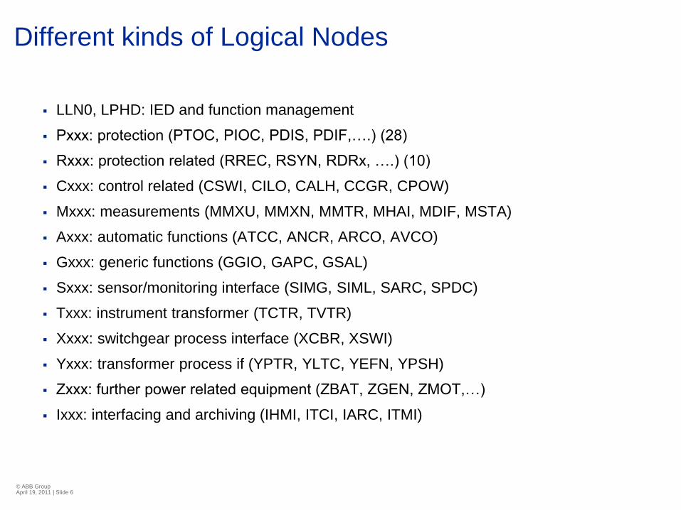
Different kinds of Logical Nodes
LLN0, LPHD: IED and function management
Pxxx: protection (PTOC, PIOC, PDIS, PDIF,….) (28)
Rxxx: protection related (RREC, RSYN, RDRx, ….) (10)
Cxxx: control related (CSWI, CILO, CALH, CCGR, CPOW)
Mxxx: measurements (MMXU, MMXN, MMTR, MHAI, MDIF, MSTA)
Axxx: automatic functions (ATCC, ANCR, ARCO, AVCO)
Gxxx: generic functions (GGIO, GAPC, GSAL)
Sxxx: sensor/monitoring interface (SIMG, SIML, SARC, SPDC)
Txxx: instrument transformer (TCTR, TVTR)
Xxxx: switchgear process interface (XCBR, XSWI)
Yxxx: transformer process if (YPTR, YLTC, YEFN, YPSH)
Zxxx: further power related equipment (ZBAT, ZGEN, ZMOT,…)
Ixxx: interfacing and archiving (IHMI, ITCI, IARC, ITMI)

© ABB Group April 19, 2011 | Slide 7
Modeling – Substation structure
230kV
Line 1 Line 2
115kV
Line X Line Y Line Z
Orlando
230kV
115 kV
Diameter 1
Diameter 2
T1
Line X
Line Y
Line Z
T1 Line 3
CB1
CB2
CB3
D1 D2
MyIEDCB13CB12CB11
CB10
Substation
Voltage Level
Bay
Orlando Substation
© ABB Group April 19, 2011 | Slide 8
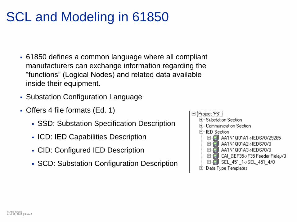
SCL and Modeling in 61850
61850 defines a common language where all compliant
manufacturers can exchange information regarding the
“functions” (Logical Nodes) and related data available
inside their equipment.
Substation Configuration Language
Offers 4 file formats (Ed. 1)
SSD: Substation Specification Description
ICD: IED Capabilities Description
CID: Configured IED Description
SCD: Substation Configuration Description

© ABB Group April 19, 2011 | Slide 9
The Basics (cont.)
Client-Server interactions
Get information from relays and meters
Higher resolution of information
Lower integration costs
Drag and drop process thanks to SCL file
All manufacturers with same naming convention
Less chances for mistakes
Faster integration
© ABB Group April 19, 2011 | Slide 10
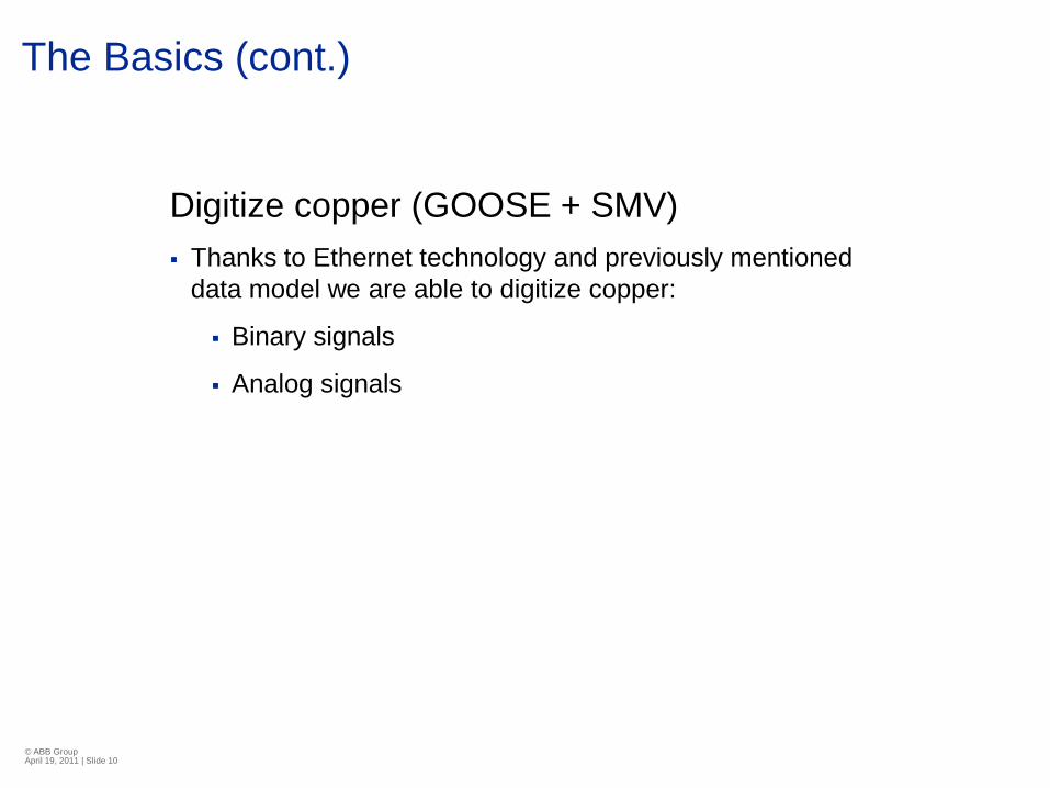
The Basics (cont.)
Digitize copper (GOOSE + SMV)
Thanks to Ethernet technology and previously mentioned
data model we are able to digitize copper:
Binary signals
Analog signals

© ABB Group April 19, 2011 | Slide 11
What is a GOOSE message?
Generic Object Oriented Substation Event
Fast and reliable distribution of information
Status (breaker position, trip, pickup, alarms, etc.)
Analog (voltage, current, counter values, etc.)
Performance
Fast messages Type 1A (Class P2/P3) received within
3ms.
This includes transmission time into the other IEDs
(similar to an output to input connection between 2
relays)
In P&C it represents a way to exchange status points
similar to inputs and outputs
© ABB Group April 19, 2011 | Slide 12
What is a GOOSE message?
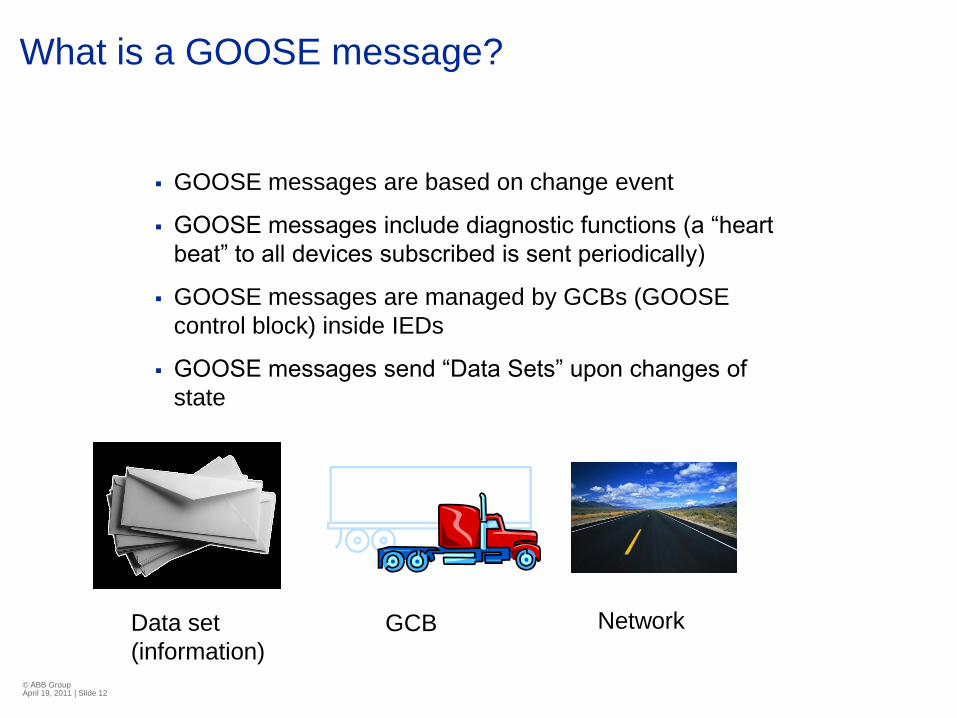
GOOSE messages are based on change event
GOOSE messages include diagnostic functions (a “heart
beat” to all devices subscribed is sent periodically)
GOOSE messages are managed by GCBs (GOOSE
control block) inside IEDs
GOOSE messages send “Data Sets” upon changes of
state
Data set
(information)
GCB Network
© ABB Group April 19, 2011 | Slide 13
What is a GOOSE message?
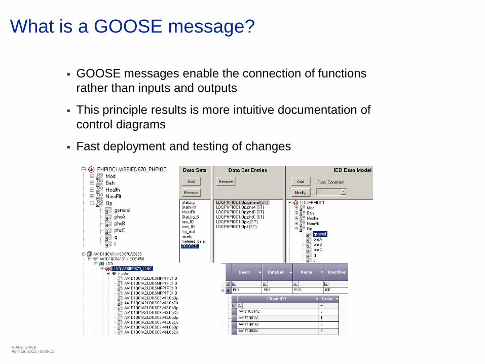
GOOSE messages enable the connection of functions
rather than inputs and outputs
This principle results is more intuitive documentation of
control diagrams
Fast deployment and testing of changes

© ABB Group April 19, 2011 | Slide 14
Applying GOOSE messages
Define an application
Anything that requires the exchange of
information within relays (done today via
hardwired connections)
Breaker Failure (VERIFY DROPOUT
REQUIREMENTS)
DFR
Transfer Scheme
Reclosing in multi breaker arrangements51/50
51/50
51/5051/5051/50
Trip Coil 50BF
52A
Trip R1 Trip R2Trip R1
Trip R1 cutoff
Trip R5Trip R4Trip R3
BF curoff
86
50BF
Alarms
Trip R2Trip R1 Trip R5Trip R4Trip R3 R1 IRFBrk1 AlarmBus 27
DFR
© ABB Group April 19, 2011 | Slide 15
Applying GOOSE messages
How about the network?
Depending on the application of GOOSE messages the
network infrastructure now becomes part of the P & C
team
Switches must comply to the same quality and
performance standards as other electronic P & C
equipment (Dielectric, SWC, RFI, etc).
Redundancy (Parallel Redundancy Protocol) to ensure
high availability and dependability of the system

© ABB Group April 19, 2011 | Slide 16
Applying GOOSE messages
System tool approach
Thanks to common file format engineering of the
SAS system can be performed under a single tool
This provides a single point of interaction with the
configuration files of all devices regardless of
manufacturer
End result (SCD file) must be part of the final
system documentation just like DC and AC
elementary are
© ABB Group April 19, 2011 | Slide 17
Applying GOOSE messages
Test and verification
Digitizing copper requires new testing techniques
and tools
These tools are available now from different
manufacturers
Visualization of results are important
See that application works: GOOD
See and record network traffic: BETTER
Network analyzers allow us to quickly diagnose
and evaluate the status of the system

© ABB Group April 19, 2011 | Slide 18
Applying GOOSE messages

© ABB Group April 19, 2011 | Slide 19
Applications for Smart Substation Design
New substation design based on IEC61850 takes full advantage of microprocessor relay features saving/reducing:
Panel Space
Hard wired connection points
Equipment
Points of failure
Testing
Documentation
Sample applications:
Breaker failure
Bus fault protection
Alarms & Station DFR
Transfer schemes
Reclosing
Sharing of status

© ABB Group April 19, 2011 | Slide 20
Conventional Breaker Fail Scheme
Panel cutoff switch
Multiple connection points
Trip Coil 50BF
52A
Trip R1 Trip R2Trip R1
Trip R1 cutoff
Trip R5Trip R4Trip R3
BF curoff
86
50BF

© ABB Group April 19, 2011 | Slide 21
Smart Breaker Fail Scheme
Utilize Relay’s HMI to
enable disable protection
elements instead of hard
wired switches
Replace multiple connection points with Peer to
Peer exchange of information (GOOSE
messages)
Trip signal from R2-R5 will be published as
GOOSE messages. The breaker fail relay R1
subscribes to these messages and will initiate its
50BF pickup timer upon sensing a trip signal.
Trip Coil 50BF
52A
Trip R1 Trip R2Trip R1
Trip R1 cutoff
Trip R5Trip R4Trip R3
BF curoff
86
50BF
© ABB Group April 19, 2011 | Slide 22
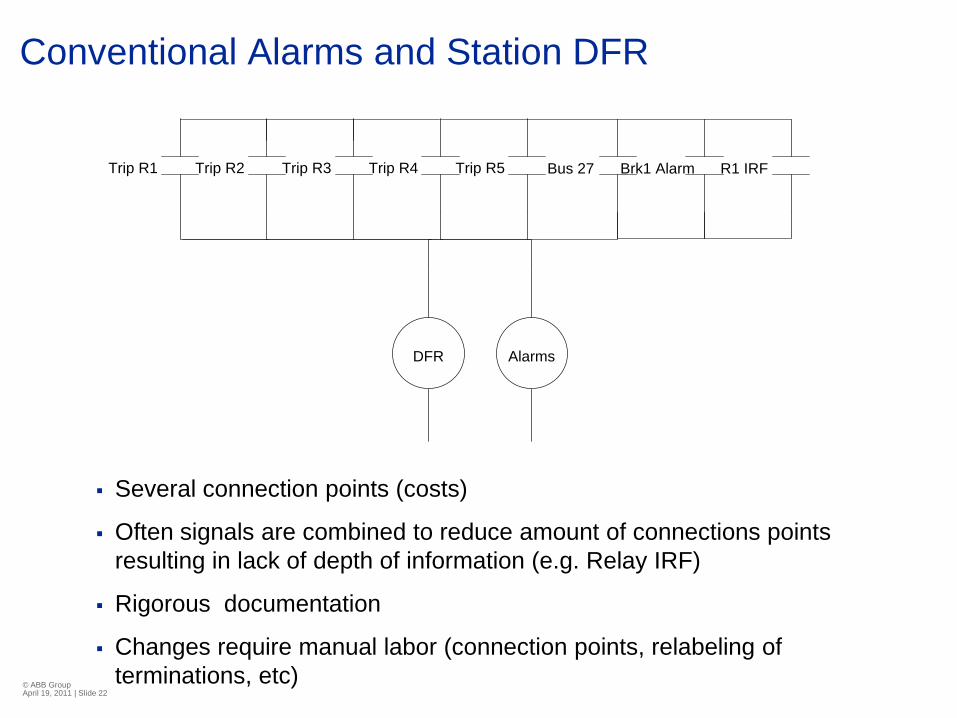
Conventional Alarms and Station DFR
Alarms
Trip R2Trip R1 Trip R5Trip R4Trip R3 R1 IRFBrk1 AlarmBus 27
DFR
Several connection points (costs)
Often signals are combined to reduce amount of connections points
resulting in lack of depth of information (e.g. Relay IRF)
Rigorous documentation
Changes require manual labor (connection points, relabeling of
terminations, etc)
© ABB Group April 19, 2011 | Slide 23
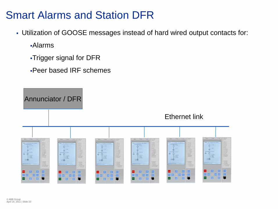
Smart Alarms and Station DFR
Annunciator / DFR
Ethernet link
Utilization of GOOSE messages instead of hard wired output contacts for:
Alarms
Trigger signal for DFR
Peer based IRF schemes

© ABB Group April 19, 2011 | Slide 24
Conventional Transfer Scheme
F1 F2 F3
Tie
F4 F5 F6
Main1 Main 2
VT1 VT2
9 Relays needed
for Feeder P&C
1 Transfer
scheme relay
Hardwired
signals:
Main1 Pos
Main2 Pos
Tie Pos
VT1
VT2

© ABB Group April 19, 2011 | Slide 25
Smart Transfer Scheme
F1 F2 F3
Tie
F4 F5 F6
Main1 Main 2
VT1 VT2
9 Relays needed for
Feeder P&C
Tie relay executes
transfer scheme logic
Hardwired signals:
Tie Pos
VT1
VT2
Signals via GOOSE:
Main1 Pos
Main2 Pos
Advanced logic to
determine load prior to
transfer and determine
if sources can handle
combined load without
equipment/apparatus
failure

© ABB Group April 19, 2011 | Slide 26
Reclosing in multi breaker arrangements

© ABB Group April 19, 2011 | Slide 27
Relion® family products
670 - Optimized for transmission
applications
650 - Optimized for transmission and
subtransmission applications
620 - Optimized for High end distribution
applications
615 - Standard series for distribution
applications
© ABB Group April 19, 2011 | Slide 27

© ABB Group April 19, 2011 | Slide 28© ABB Group April 19, 2011 | Slide 28
Relion® family products
One common tool for all Relion® products, Protection
and Control Manager PCM600
Covers all applications, from interconnected
transmission grids to secondary distribution networks
The performance of Relion protection and control
IEDs meet the comprehensive IEC 61850
communication tasks, for example, GOOSE
messaging for peer-to-peer communication
The Relion IEDs utilize ABB’s unique connectivity
package concept
The Relion product family provides configured, pre-
configured or fully customized IEDs
Family Highlights

© ABB Group April 19, 2011 | Slide 29
The value of implementing 61850
Cost reduction
Reduction of copper hardwires wires
Eliminate terminations/terminal blocks
Reduce testing intervals due to self monitoring
Reduce documentation e.g. DC elementary
Faster integration
Improved performance:
Faster than conventional binary inputs and outputs
Increased reliability due to repetitive messages

© ABB Group April 19, 2011 | Slide 30
QUESTIONS?


![Oral Beason- Major Project 1 - FINAL - LPHD 702[1]](https://img.pdfslide.net/doc/110x75/577d26381a28ab4e1ea092f8/oral-beason-major-project-1-final-lphd-7021.jpg)