Embed Size (px)
Citation preview
Alignment of challenging image pairs: Refinement and region growingstarting from a single keypoint correspondence
Gehua Yang1 Charles V. Stewart1 Michal Sofka1 Chia-Ling Tsai1,2
1 Rensselaer Polytechnic Institute2National Chung Cheng UniversityTroy, NY 12180, U.S.A. Chiayi, Taiwan 621, R.O.C.
{yangg2,stewart,sofka,tsaic}@cs.rpi.edu
Abstract
Our goal is a registration algorithm capable of align-ing image pairs having some combination of low overlap,large illumination differences (e.g. day and night), substan-tial scene changes and different modalities. Our approachstarts by extracting and matching keypoints. Ranked-ordered matches are tested individually in succession. Eachis used to generate a transformation estimate in a small im-age region surrounding the keypoints. The growth processworks by iterating three steps: 1) refining the estimate bysymmetrically matching features on the two images, 2) ex-panding the region according to the uncertainty in the map-ping, 3) selecting an appropriate transformation model. Im-age features are corner points and face points located byanalyzing the intensity structure of image neighborhoods.After convergence, if a correctness test verifies the transfor-mation it is accepted and the algorithm ends; otherwise theprocess starts over with the next keypoint match. Experi-mental results on a suite of challenging image pairs showsthat the algorithm substantially out-performs recent algo-rithms based on keypoint matching.
1 Introduction
This paper addresses the problem of developing an imageregistration algorithm that can work on many different typesof images, scenes, and illumination conditions. The algo-rithm should successfully align pairs of images taken of in-door or outdoor scenes, and in natural or man-made envi-ronments. It should be able to align images taken at dif-ferent times of day, during different seasons of the year, orusing different imaging modalities. The algorithm shouldadjust for rotation and zoom between the images and forlow image overlap. Our primary assumption is that the im-ages to be aligned should be spatially-related by a knowntransformation model — the most common model being aplanar projective transformation. Such a registration algo-rithm will have numerous applications ranging from mosaic
construction to change detection and visualization.In order to make the difficulty of general-purpose regis-
tration concrete, we have gathered a test suite of 18 chal-lenging image pairs, some of which are shown in Figures 1-3.1 The alignment is clear to the human observer for eachpair but difficult for current registration algorithms. Twocrucial issues emerge from examining and experimentingwith these images. First, initialization is difficult. Recentlydeveloped keypoint detection and matching algorithms onlyproduce a small number of correct matches, occasionallynone and sometimes fewer than 10 out of the top 100. Sec-ond, there is often no relationship between the intensitiesfor a large fraction of the image pixels. For example, inthe winter-summer pair from Figure 3, snow on the roofsin winter produces homogeneous intensity regions, wherethese roofs appear as dark, textured regions in the summerimage.
The key idea behind our proposed algorithm is to start atjust one corresponding location and grow, discovering con-sistency between images as part of the alignment process.This intuition is realized in several important steps:
1. The algorithm starts by matching keypoints. Eachmatch is used individually to generate an initial sim-ilarity transformation, which is roughly accurate in asmall image region. This means the algorithm can suc-ceed even if only one keypoint match is correct.
2. The initial transformation is “grown” into an image-wide alignment by iterating steps of matching, robustrefinement, model selection and region growing, con-trolled by the transformation estimate error and uncer-tainty. (This process, called the “Dual-Bootstrap,” wasoriginally developed for retinal images — referenceomitted.) The growth and refinement process keepsthe alignment accurate within the growing region, us-ing robust techniques to select only the constraints thatare consistent.
1All of these will be available through our website.
1
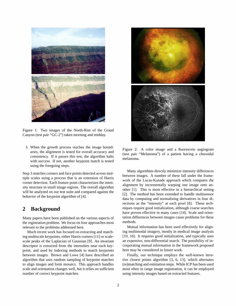
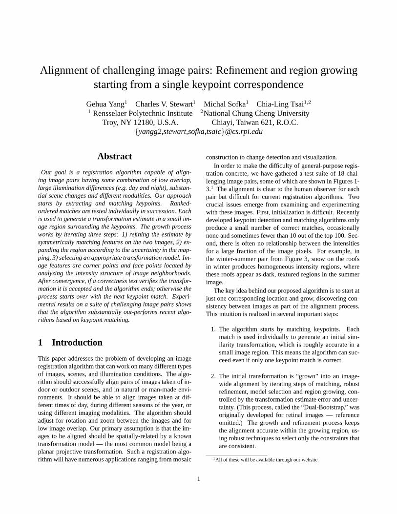
Figure 1: Two images of the North-Rim of the GrandCanyon (test pair “GC-2”) taken morning and midday.
3. When the growth process reaches the image bound-aries, the alignment is tested for overall accuracy andconsistency. If it passes this test, the algorithm haltswith success. If not, another keypoint match is testedusing the foregoing steps.
Step 3 matches corners and face points detected across mul-tiple scales using a process that is an extension of Harriscorner detection. Each feature point characterizes the inten-sity structure in small image regions. The overall algorithmwill be analyzed on our test suite and compared against thebehavior of the keypoint algorithm of [4].
2 Background
Many papers have been published on the various aspects ofthe registration problem. We focus on four approaches mostrelevant to the problems addressed here.
Much recent work has focused on extracting and match-ing multiscale keypoints, either Harris corners [11] or scale-scale peaks of the Laplacian of Gaussian [9]. An invariantdescriptor is extracted from the intensities near each key-point, and used by indexing methods to match keypointsbetween images. Brown and Lowe [4] have described analgorithm that uses random sampling of keypoint matchesto align images and form mosaics. This approach handlesscale and orientation changes well, but it relies on sufficientnumber of correct keypoint matches.
Figure 2: A color image and a fluorescein angiogram(test pair “Melanoma”) of a patient having a choroidalmelanoma.
Many algorithms directly minimize intensity differencesbetween images. A number of these fall under the frame-work of the Lucas-Kanade approach which computes thealignment by incrementally warping one image onto an-other [1]. This is most effective in a hierarchical setting[2]. The method has been extended to handle multisensordata by computing and normalizing derivatives in four di-rections as the “intensity” at each pixel [8]. These tech-niques require good initialization, although coarse searcheshave proven effective in many cases [14]. Scale and orien-tation differences between images cause problems for thesemethods.
Mutual information has been used effectively for align-ing multimodal imagery, mostly in medical image analysis[10, 16]. It requires good initialization, and typically usesan expensive, non-differential search. The possibility of in-corporating mutual information in the framework proposedhere may be considered in future work.
Finally, our technique employs the well-known itera-tive closest points algorithm [3, 6, 13], which alternates(re)matching and estimation steps. While ICP has been usedmost often in range image registration, it can be employedusing intensity images based on extracted features.
2
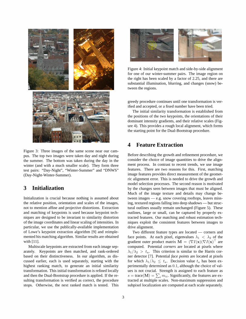
Figure 3: Three images of the same scene near our cam-pus. The top two images were taken day and night duringthe summer. The bottom was taken during the day in thewinter (and with a much smaller scale). They form threetest pairs: “Day-Night”, “Winter-Summer” and “DNWS”(Day-Night-Winter-Summer).
3 Initialization
Initialization is crucial because nothing is assumed aboutthe relative position, orientation and scales of the images,not to mention affine and projective distortions. Extractionand matching of keypoints is used because keypoint tech-niques are designed to be invariant to similarity distortionof the image coordinates and linear scaling of intensities. Inparticular, we use the publically-available implementationof Lowe’s keypoint extraction algorithm [9] and reimple-mented his matching algorithm. Similar results are obtainedwith [11].
Multiscale keypoints are extracted from each image sep-arately. Keypoints are then matched, and rank-orderedbased on their distinctiveness. In our algorithm, as dis-cussed earlier, each is used separately, starting with thehighest ranking match, to generate an initial similaritytransformation. This initial transformation is refined locallyand then the Dual-Bootstrap procedure is applied. If the re-sulting transformation is verified as correct, the procedurestops. Otherwise, the next ranked match is tested. This
Figure 4: Initial keypoint match and side-by-side alignmentfor one of our winter-summer pairs. The image region onthe right has been scaled by a factor of 2.25, and there aresubstantial illumination, blurring, and changes (snow) be-tween the regions.
greedy procedure continues until one transformation is ver-ified and accepted, or a fixed number have been tried.
The initial similarity transformation is established fromthe positions of the two keypoints, the orientations of theirdominant intensity gradients, and their relative scales (Fig-ure 4). This provides a rough local alignment, which formsthe starting point for the Dual-Bootstrap procedure.
4 Feature Extraction
Before describing the growth and refinement procedure, weconsider the choice of image quantities to drive the align-ment process. In contrast to recent trends, we use imagefeatures. There are two reasons for this. First, matchingimage features provides direct measurement of the geomet-ric alignment error. This is needed to drive the growth andmodel selection processes. The second reason is motivatedby the changes seen between images that must be aligned.Much of the image texture and details may change be-tween images — e.g. snow covering rooftops, leaves miss-ing, textured regions falling into deep shadows — but struc-tural outlines usually remain unchanged (Figure 5). Theseoutlines, large or small, can be captured by properly ex-tracted features. Our matching and robust estimation tech-niques exploit the consistent features between images todrive alignment.
Two different feature types are located — corners andface points. At each pixel, eigenvaluesλ1 < λ2 of thegradient outer product matrixM = (∇I(x)(∇I(x)> arecomputed. Potentialcornersare located at pixels whereλ1/λ2 > ta. This criterion is similar to the Harris cor-ner detector [7]. Potentialface pointsare located at pixelsfor which λ1/λ2 ≤ ta. Decision valueta has been ex-perimentally determined as0.1, although the choice of val-ues is not crucial. Strength is assigned to each feature ass = trace(M) =
∑i mii. Significantly, the features are ex-
tracted at multiple scales. Non-maximum suppression andsubpixel localization are computed at each scale separately.
3
Figure 5: Examples of substantial changes between imageregions due to illumination differences, scale differences,and changes (snow).
The next steps are designed to avoid difficulties due tolow image contrast and threshold effects. First, a very lowthreshold,ts is applied to the strength — on the order ofone grey level — to eliminate plainly noise edges. Next, aminimum number of strongest features is kept without fur-ther testing. Then each remaining point is tested in orderof decreasing strength to ensure that it has locally largeststrength and it is not close to other features. This proce-dure stops when a maximum number of features is found.A minimum distance between features is set to ensure thatthese are spread through the image, and this distance growswith scale. The resulting features are calledmatchable fea-tures. The second and final step is to extract a reduced sub-set by increasing the spacing and strength parameters to ob-tain a set ofdriving features(similar to those in [15]). Driv-ing features are transformed and matched against matchablefeatures.
A course-scale example set of driving features is shownin Figure 6. Features are spread throughout the image. Ineffect the features represent summaries of local image struc-ture: when a region contains substantial spatial variationsin all directions a corner is placed at the location of locallygreatest strength; when a region contains variation in onedirection, a face point is placed, again at the (subpixel) loca-tion of locally greatest strength; when variation is insignifi-cant, no feature is placed.
5 DB-ICP
The Dual-Bootstrap ICP (DB-ICP) algorithm begins withan initial transformation estimate and initial matching re-gions from the two images obtained by keypoint matching.The algorithm iterates steps of (1) refining the current trans-formation in the current “bootstrap” region by symmetric
Figure 6: Example intermediate resolution driving features,which are more sparse than matchable features. Circles arecorners and line segments are face points, oriented along thedirection of greatest eigenvalue. As the resolution increases,the feature sets become much denser, and the proportion offace points vs. corner points increases substantially.
matching,R, (2) applying model selection to determine ifa more sophisticated model may be used, and (3) expand-ing the region, growing inversely proportional to the uncer-tainty of the mapping on the region boundary (Figure 7).While the framework of this algorithm has been describedelsewhere for retinal image registration (ref omitted), manyof the details must be changed and extended to make the ap-proach work for a wider class of images. These details areemphasized in the remainder of this section.
5.1 Notation
The two images areIp andIq. The matchable corner andface points arePc = {pc} andPf = {pf} from Ip andQc = {qc} andQf = {qf} from Iq. Points from all scalesare combined to form these sets. Driving features sets aresubsets ofPc,Pf ,Qc, andQf . The transformation of pointlocationx is T(x;θ), whereθ is the parameter vector tobe estimated. An estimate isθ, and its covariance matrix isΣˆθ
. The initial model computed from the keypoint matchis a similarity transformation. Model selection transitionsfrom similarity to affine to homography, and in some casesto a homography plus radial-lens distortion or, in the caseof retinal images, a quadratic transformation. Finally, theregion over which the transformation is being estimated iscalled the “bootstrap” region, and is denoted byR.
5.2 Refinement Within the Bootstrap Region
The transformation is refined within current bootstrap re-gion R, ignoring everything else in the two images. The
4
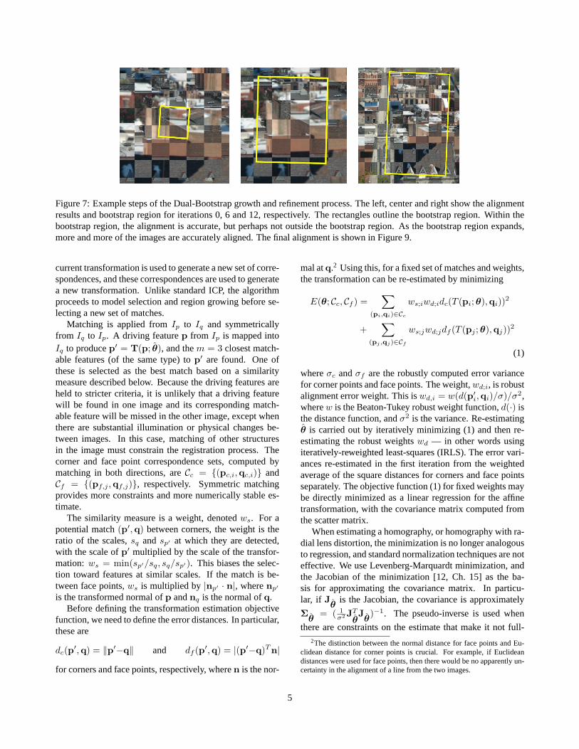
Figure 7: Example steps of the Dual-Bootstrap growth and refinement process. The left, center and right show the alignmentresults and bootstrap region for iterations 0, 6 and 12, respectively. The rectangles outline the bootstrap region. Within thebootstrap region, the alignment is accurate, but perhaps not outside the bootstrap region. As the bootstrap region expands,more and more of the images are accurately aligned. The final alignment is shown in Figure 9.
current transformation is used to generate a new set of corre-spondences, and these correspondences are used to generatea new transformation. Unlike standard ICP, the algorithmproceeds to model selection and region growing before se-lecting a new set of matches.
Matching is applied fromIp to Iq and symmetricallyfrom Iq to Ip. A driving featurep from Ip is mapped intoIq to producep′ = T(p; θ), and them = 3 closest match-able features (of the same type) top′ are found. One ofthese is selected as the best match based on a similaritymeasure described below. Because the driving features areheld to stricter criteria, it is unlikely that a driving featurewill be found in one image and its corresponding match-able feature will be missed in the other image, except whenthere are substantial illumination or physical changes be-tween images. In this case, matching of other structuresin the image must constrain the registration process. Thecorner and face point correspondence sets, computed bymatching in both directions, areCc = {(pc,i,qc,i)} andCf = {(pf,j ,qf,j)}, respectively. Symmetric matchingprovides more constraints and more numerically stable es-timate.
The similarity measure is a weight, denotedws. For apotential match(p′,q) between corners, the weight is theratio of the scales,sq andsp′ at which they are detected,with the scale ofp′ multiplied by the scale of the transfor-mation: ws = min(sp′/sq, sq/sp′). This biases the selec-tion toward features at similar scales. If the match is be-tween face points,ws is multiplied by|np′ · n|, wherenp′
is the transformed normal ofp andnq is the normal ofq.Before defining the transformation estimation objective
function, we need to define the error distances. In particular,these are
dc(p′,q) = ‖p′−q‖ and df (p′,q) = |(p′−q)T n|
for corners and face points, respectively, wheren is the nor-
mal atq.2 Using this, for a fixed set of matches and weights,the transformation can be re-estimated by minimizing
E(θ; Cc, Cf ) =∑
(pi,qi)∈Cc
ws;iwd;idc(T (pi;θ),qi))2
+∑
(pj ,qj)∈Cf
ws;jwd;jdf (T (pj ;θ),qj))2
(1)
whereσc andσf are the robustly computed error variancefor corner points and face points. The weight,wd;i, is robustalignment error weight. This iswd,i = w(d(p′i,qi)/σ)/σ2,wherew is the Beaton-Tukey robust weight function,d(·) isthe distance function, andσ2 is the variance. Re-estimatingθ is carried out by iteratively minimizing (1) and then re-estimating the robust weightswd — in other words usingiteratively-reweighted least-squares (IRLS). The error vari-ances re-estimated in the first iteration from the weightedaverage of the square distances for corners and face pointsseparately. The objective function (1) for fixed weights maybe directly minimized as a linear regression for the affinetransformation, with the covariance matrix computed fromthe scatter matrix.
When estimating a homography, or homography with ra-dial lens distortion, the minimization is no longer analogousto regression, and standard normalization techniques are noteffective. We use Levenberg-Marquardt minimization, andthe Jacobian of the minimization [12, Ch. 15] as the ba-sis for approximating the covariance matrix. In particu-lar, if Jˆθ
is the Jacobian, the covariance is approximately
Σˆθ= ( 1
σ2 JTˆθJˆθ
)−1. The pseudo-inverse is used when
there are constraints on the estimate that make it not full-2The distinction between the normal distance for face points and Eu-
clidean distance for corner points is crucial. For example, if Euclideandistances were used for face points, then there would be no apparently un-certainty in the alignment of a line from the two images.
5
rank. The approach works with the homography combinedwith radial-lens distortion.
Overall, this minimization process is applied to estimatethe mapping fromIp to Iq by reversing the roles of the fea-ture sets but keeping the correspondences, fromIq to Ip.
5.3 Model Selection Criterion
Due to the characteristics of the region growing and the for-mation of new match sets, we only consider switching fromlower order models to high order, more sophisticated mod-els. This must be done carefully: switching to a higher-order model too soon causes the estimate to be distorted bynoise; switching too late causes an increase in error vari-ancesσ2
c andσ2f and misalignment on the bootstrap region
boundary. Model selection techniques have been studiedextensively in the literature. In our work we have found thatthe earlier and quite simple yet effective Akaike Informa-tion Criteria, with a small-sample bias adjustment as rec-ommended in [5]:
− | Cc | log(σc)− | Cf | log(σf )−E(θ; Cc, Cf )+nk
n− k − 1,
(2)wherek is the degrees of freedom in current model andn =2 | Cc | + | Cf | is the effective number of constraints.
Expression (2) is evaluated for each model using fixedmatch sets after IRLS is applied for each model as describedearlier. The final error distances,dc or df , of each corre-spondence are then used to evaluate expression (2) for eachmodel. The model that minimizes (2) is then selected forthe next iteration of the Dual-Bootstrap.
5.4 Region Growth
Region growth depends on the uncertainty in the trans-formation estimate, as represented by covariance matrixΣˆθ
. In particular, expansion is inversely proportional to thetransfer error — the error in applying the estimated trans-formation to points on the boundary of the bootstrap region.If x is such a point location (not a feature point) andJ isthe Jacobian of transformationT with respect toθ, evalu-ated atx, then the error covariance of the mapping ofx isΣx = JΣˆθ
JT . Suppose now thatx is chosen at the cen-ter of a side of bootstrap regionR and the outward direction(away from the center of the region) isn. Then the mappingerror variance in the outward direction isnT Σxn. Finally,this side of the rectangle expands outward inversely propor-tional tonT Σxn, which means that more uncertainty leadsto slower growth. This is applied independently to each sideof the rectangle.
6 Decision Criteria
Once the iterative Dual-Bootstrap procedure just describedexpands to cover the apparent overlap between images(based on the estimated transformation), and the refinementprocess has converged, the final alignment must be testedfor correctness. As discussed above, if this confirms thatthe transformation is correct, the images are considered tobe aligned, and the algorithm stops. Otherwise, the nextkeypoint match is tested using the initial refinement andDual-Bootstrap procedures.
The decision criteria is composed of two parts: accu-racy and consistency. The accuracy,τ , is measured as theweighted average alignment error for the final match set, us-ing the weights and distance measures defined above, andonly face points because these are more accurately posi-tioned. Consistency,ρ, is harder to define because of dif-ferences between image modalities and illuminations, andbecause of scene changes.
The measure we use is the absolute difference in normaldirections (measured as an angle) between face point cor-respondences(p′f,j ,qf,j), wherep′f,j is the transformedpoint. We calculate a histogram,h of orientation differ-ences in the range[0, π/2] using all face correspondences.If the transformation is incorrect, this angle difference willtend toward being uniformly distributed within the range;whereas if the images are well-aligned, the histogram willtend to have a strong peak near 0 degrees. We measure thisby computing the Bhattacharya measure betweenh and auniform distribution and betweenh and an exponential dis-tribution. Denoting these distances asbu andbe, our con-sistency measure is the ratio of distances,ρ = be/bu. Smallvalues ofρ correspond to well-aligned images.
We use two thresholds for each of the measures:TL <TH for τ andPL < PH for ρ. Whenτ < TL andρ < PL,the alignment estimate is simply accepted as correct. DB-ICP alignment results in this case are accurate to less thana pixel (TL = 1.0) and no substantial improvement can bemade. Whenτ > TH or ρ > PH , the estimate is apparentlyincorrect and is thrown away. The algorithm then moves tothe next keypoint correspondence, as described above. Oth-erwise the estimate is are saved and the next initial match isconsidered. At the end, the estimate that has the minimumalignment errorτ is chosen as the final estimate. If no es-timate has bothτ < TH andρ < PL, the images are leftunregistered.
Finally, we can use the decision criteria above as a ter-mination criteria, allowing the algorithm to quickly rejectincorrect alignments early in the process. We let the DB-ICP loop run for 3 iterations before testing. In additionto the measures defined above, we also include a measurethat detected extreme scale changes between images. Thethresholds used are the same for all experiments.
6
7 Experiments
We have applied the keypoint matching, initial estimationand Dual-Bootstrap algorithm just described to the 18 im-ages pairs in our test suite. The images in the suite range insize from676× 280 to 1504× 1000. It tries up to 100 ini-tial rank-ordered keypoint matches before declaring that theimages can not be aligned. Although we test the Lowe key-points based on a rank-ordering, we do not apply a thresholdon the ratio to restrict the number of matches. This is im-portant for aligning medical images because the keypointmatches are not distinct. Finally, for multi-modal imagesinvolving contrast reversals, we invert the intensities of oneof the images before extracting keypoints.
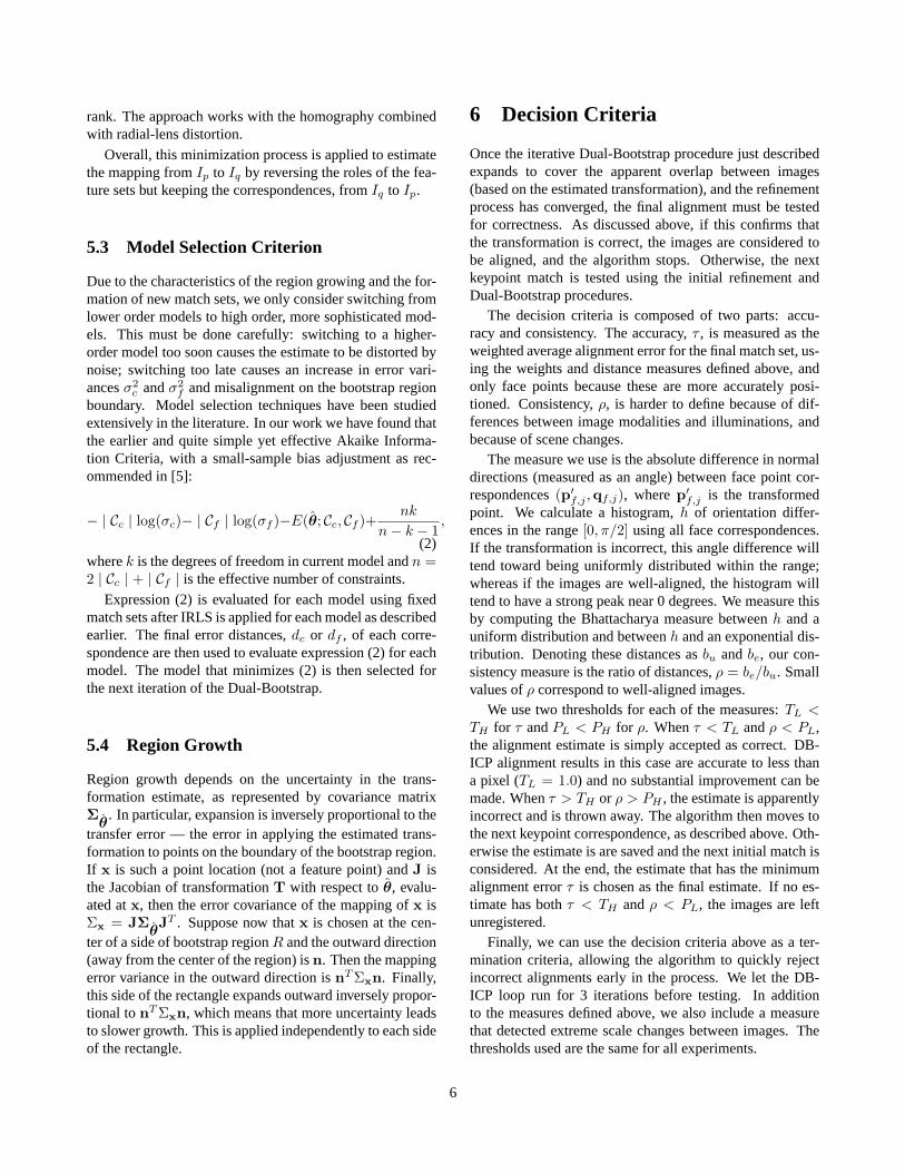
The algorithm successfully aligns 15 of the 18 pairs, in-cluding pairs from Figures 1-3 except “DNWS” from Fig-ure 3. Example checkerboard mosaics showing the align-ment results are shown in Figures 8 and 9. We have alsoapplied the new algorithm to other, easier image pairs withuniversal success. Finally, when tested on image pairsthat have no overlap, the new algorithm has not yet falselyaligned a pair. For some image pairs we achieved subpixelaccuracy by using homography with radial lens distortionmodel, whereas visible misalignments are apparent whenusing the homography only.
To show the significance of these results, the publically-available code for the Autostitch keypoint matching algo-rithm of [4] produced 1 accurately aligned pair and 4 pairswith visible misalignments; on 13 pairs it failed altogether.(Autostich was run with the original parameters.) None ofimages in Figures 1-3 were successfully aligned.
More about the behavior of our algorithm and the causesfor the failure of the random-sampling keypoint match al-gorithm can be understood by using studying the verifiedalignment for 9 of these pairs. This alignment is used to de-termine which matches are correct based on mapped loca-tion, orientation, and scale. In two image pairs, there wereno correct keypoint matches that passed the threshold ratiotest. In two others, there were only three. For the remain-ing pairs, there were sufficient numbers of correct matches,but only 10%-22% of the overall match set. Finding a goodrandom sample with such a small fraction of inliers leads toan exponential growth in the number of samples required.
By contrast, our algorithm usually succeeded with thefirst correct match it tested. In most cases, the success-ful match was among the first ten. The worst case wasthe 34th match. On the challenging winter-summer pair,we let our algorithm run on each of the correct keypointmatches, and found that on 9 out the 11 pairs it produced analignment that passed the final consistency tests. In general,the Dual-Bootstrap procedure converges in 10-20 iterationswhen started from a correct match. Finally, the failures ofour algorithm may generally be attributed to initialization:
Figure 8: Checkerboard mosaics showing the accuracy ofthe alignment for the GC-2 and Melanoma pairs from Fig-ures 1 and 2.
on each of the three pairs in our test suite in which the algo-rithm failed, a simple manual initialization in a small imageregion, followed by application of the Dual-Bootstrap pro-cedure, led to a consistent alignment.
As a last comment, our algorithm is not as expensiveas one would imagine. On the melanoma pair the cost isabout 0.25s per initial match, whereas on the larger winter-summer pair the cost is 3.1s per initial match. Aside fromimage size, the difference in the costs is primarily due tothe earlier termination criteria, which is much more effec-tive on melanoma images. All the performance results aremeasured on a Pentium IV 3.2GHz PC.
8 Summary and Conclusion
We have presented an algorithm designed to register a widevariety of images, and analyzed it on a challenging suite oftest image pairs. The crucial properties of the algorithm in-clude (1) keypoint matching, (2) generating and testing sim-ilarity transformations based on a single keypoint match,
7
inin
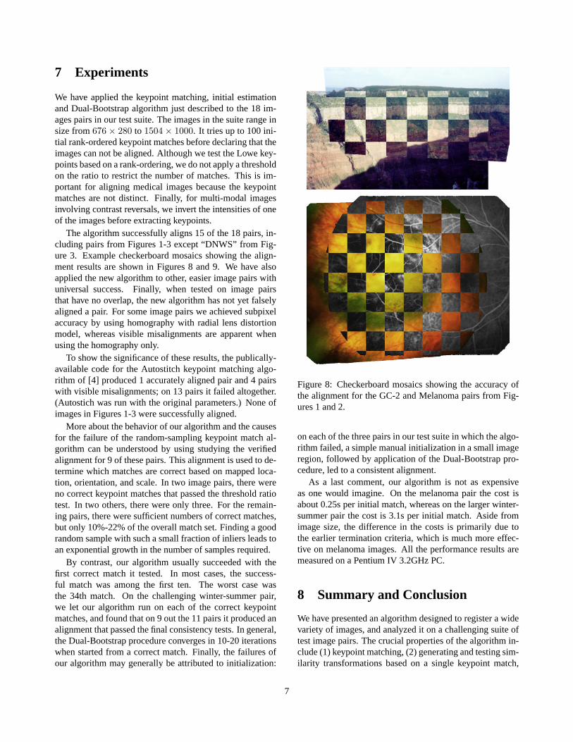
Figure 9: Checkerboard mosaics showing the accuracy ofthe alignment for the Day-Night and Winter-Summer pairsfrom Figure 3.
and (3) growing and refining alignments using a combina-tion of symmetric feature matching, robust re-estimation ofthe transformation, model selection, and region growing. Aconsistency test successfully determines which transforma-tion estimates are correct and can be used to quickly elimi-nate obviously incorrect estimates. The algorithm success-fully aligned 15 of the 18 pairs in the challenge suite, sub-stantially outperforming a recent algorithm based on key-point matching alone. The algorithm routinely handles awide variety of much easier image pairs.
The algorithm works effectively when at least one key-point match is correct and when there is sufficient consistentstructure between the images to drive the Dual-Bootstrapprocedure — even when much of the structure is inconsis-tent due to physical and illumination changes or differencesin modality. The algorithm fails primarily when there is
no keypoint match to gain an initial toe-hold on the correctalignment.
Our future work is headed in several directions. First,we are re-addressing the initialization problem — the mostimportant issue for improving the performance of this al-gorithm in particular and registration techniques in general.Second, we are pursuing a variety of applications. Third, weare generalizing it to a multi-image registration algorithm.
References[1] S. Baker and I. Matthews. Lucas-kanade 20 years on: A
unifying framework.IJCV, 56(3):221–255, 2004.
[2] J. Bergen, P. Anandan, K. Hanna, and R. Hingorani. Hi-erarchical model-based motion estimation. InProc. SecondECCV, pages 237–252, 1992.
[3] P. Besl and N. McKay. A method for registration of 3-dshapes.IEEE T. Pattern Anal., 14(2):239–256, 1992.
[4] M. Brown and D. Lowe. Recognising panoramas. InProc.ICCV, 2003.
[5] K. P. Burnham and D. R. Anderson.Model Selectionand Inference: A practical Information-theorectic Approach.Springer, 1st edition, 1998.
[6] Y. Chen and G. Medioni. Object modeling by registration ofmultiple range images.IVC, 10(3):145–155, 1992.
[7] C. Harris and M. Stephens. A combined corner and edgedetector. pages 147–151.
[8] M. Irani and P. Anandan. Robust multisensor image align-ment. InProc. ICCV, pages 959–966, 1998.
[9] D. G. Lowe. Distinctive image features from scale-invariantkeypoints.IJCV, 60(2):91–110, November 2004.
[10] F. Maes, A. Collignon, D. Vandermeulen, G. Marchal, andP. Suetens. Multimodality image registration by maximiza-tion of mutual information. IEEE Trans. Med. Imaging.,16(2):187–198, 1997.
[11] K. Mikolajczyk and C. Schmid. Scale and affine invariantinterest point detectors.IJCV, 60(1):63–86, 2004.
[12] W. H. Press, S. A. Teukolsky, W. T. Vetterling, and B. P. Flan-nery. Numerical Recipes in C: The Art of Scientific Comput-ing. Cambridge University Press, 1992.
[13] S. Rusinkiewicz and M. Levoy. Efficient variants of the ICPalgorithm. InProc. Third Int. Conf. on 3-D Digital Imagingand Modeling, pages 224–231, 2001.
[14] H. Sawhney, S. Hsu, and R. Kumar. Robust video mosaicingthrough topology inference and local to global alignment. InProc. 5th ECCV, volume II, pages 103–119, 1998.
[15] D. Shen and C. Davatzikos. Hammer: Hierarchical attributematching mechanism for elastic registration.IEEE Trans.Med. Imaging., 21(11):1421–1439, 2002.
[16] P. Viola and W. M. Wells III. Alignment by maximization ofmutual information.IJCV, 24(2):137–154, 1997.
8


![Challenging the sleep homeostat: Sleep in depression is ... · S. Frey ⇑, A. Birchler ... [23]. A refinement of this suggests that depression might bear sleep-related similarities](https://img.pdfslide.net/doc/110x75/605066ba76e8ca59ab09fa5d/challenging-the-sleep-homeostat-sleep-in-depression-is-s-frey-a-a-birchler.jpg)