Embed Size (px)
Citation preview
All About
ServicingTop Freezer Refrigerator
™
Publication #5995562831 May 2010
Electrolux Major Appliances; North America250 Bobby Jones ExpwyAugusta, GA 30907
1:1
Section 1 - Basic InformationSafe Servicing Practices
Avoid personal injury and/or property damage by observing important Safe Servicing Practices. Following are some limited examples of safe practices:
1. DO NOT attempt a product repair if you have any doubts as to your ability to complete the repair in a safe and satisfactory manner.
2. Always Use The Correct Replacement Parts as indicated in the parts documentation. Substitutions may defeat compliance with Safety Standards Set For Home Appliances.
3. Before servicing or moving an appliance: • Remove power cord from the electrical outlet, trip circuit breaker to OFF position, or remove fuse. • Turn off water supply if needed. • Turn off gas supply for gas dryers.
4. Never interfere with the proper operation of any safety device.
5. Use ONLY REPLACEMENT PARTS CATALOGED FOR THIS APPLIANCE. Substitutions may defeat compliance with Safety Standards Set For Home Appliances.
6. GROUNDING: The standard color coding for safety ground wires is GREEN, or GREEN with YELLOW STRIPES. Ground leads are not to be used as current carrying conductors.
It is EXTREMELY important that the service technician reestablish all safety grounds prior to completion of service. Failure to do so will create a hazard.
7. Prior to returning the product to service, ensure that: • All electrical connections are correct and secure. • All electrical leads are properly dressed and secured away from sharp edges, high temperature components, and
moving parts. • All non-insulated electrical terminals, connectors, heaters, etc. are adequately spaced away from all metal parts
and panels. • All safety grounds (both internal and external) are correctly and securely connected. • All panels are properly and securely reassembled. • Gas and water supplies are turned ON if shut off prior to service.
ATTENTION!!!This service manual is intended for use by persons having electrical and mechanical training and a level of knowledge of these subjects generally considered acceptable in the appliance repair trade. Electrolux Home Products, Inc. cannot be responsible, nor assume any liability, for injury or damage of any kind arising from the use of this manual.
© 2010 Electrolux Home Products, Inc.

1:2
Section 6 - Air CirculationAutomatic Defrost Models ...................................... 6:1Principals of Automatic Defrost Operation ............. 6:1Air Circulation Patterns ........................................ 6:1
Section 7 - Refrigeration SystemDefinitions ............................................................ 7:1Recovery ............................................................ 7:1Recycling ........................................................... 7:1Reclaim .............................................................. 7:1
Safety Warnings ................................................... 7:1Compressor Testing ............................................ 7:1Charging Sealed Systems .................................... 7:1Soldering ........................................................... 7:2
Basic Components ................................................ 7:2Perimeter Hot Tube ............................................... 7:2Refrigerant Cycle .................................................. 7:2Lor or High Side Leak or Undercharge .................... 7:2Testing for Refrigerant Leaks ................................. 7:3Checking for Internal (Hot Tube) Leaks .................. 7:3Compressor Replacement ...................................... 7:3To flush the system ............................................. 7:4To use dry nitrogen to flush the system ................ 7:4To use refrigerant to flush the system .................. 7:4
Installing a New Compressor ................................. 7:4Evaporator Replacement ....................................... 7:7Heat Exchanger Replacement ................................ 7:8To replace the heat exchanger: ............................ 7:8
Perimeter Hot Tube Repair Kit ................................ 7:9Bypassing Perimeter Hot Tube - Step 1 ................. 7:9Installing the Heater Wire - Step 2 ..................... 7:10Installing the Heater Wire - Step 3 ..................... 7:10
Condenser Replacement ...................................... 7:10Suction Line and Capillary Tube Replacement ....... 7:11Filter-Drier Installation ........................................ 7:11Evacuating and Recharging ................................. 7:11
Section 1 - Basic InformationSection 1 - Basic Information
Safe Servicing Practices - All Appliances ................. 1:1Table of Contents ................................................. 1:2
Section 2 - Important Safety InstructionsImportant safety instructions ................................. 2:1Electrical information ............................................ 2:2Installation ........................................................... 2:3Uncrating ........................................................... 2:3Model and Serial Number .................................... 2:3Air Circulation ..................................................... 2:3Leveling ............................................................. 2:3Door Removal and Reversal Instructions ............... 2:4Door Alignment ................................................ 2:10Connecting the Water Supply............................. 2:10
Section 3 - Refrigerator OperationControls ............................................................... 3:1Cool Down Period ............................................... 3:1Refrigerator and Freezer Controls......................... 3:1Temperature Adjustment ..................................... 3:1
Ice Service ........................................................... 3:2Turning the ice maker on and off ......................... 3:2Ice Production: What to Expect ........................... 3:2
Normal Operating Sounds & Sights ........................ 3:3Understanding the sounds you may hear .............. 3:3
Care and Cleaning ................................................ 3:4Protecting your investment .................................. 3:4Care & Cleaning tips ........................................... 3:5Replacing Light Bulbs .......................................... 3:5
Before You Call ..................................................... 3:6
Section 4- Refrigerator CabinetBasic Construction ................................................ 4:1Compressor Mounting ........................................... 4:1Insulation and Inner Liner ..................................... 4:1Cabinet Doors and Gaskets .................................... 4:1Door Rack Replacement ........................................ 4:1Front and Rear Rollers .......................................... 4:1To Remove Front Roller Assembly ........................ 4:2To Remove Rear Roller ........................................ 4:2
Control Housing .................................................... 4:2Cabinet Touch-Up Procedure ................................. 4:2Lacquer Refinishing ............................................. 4:2
Section 5 - Electrical ComponentsElectrical Grounding .............................................. 5:1Compressor Electrical Components and Circuits ..... 5:1To Check/Replace Relay ...................................... 5:2Overload protector .............................................. 5:2To Check/Replace the Overload Protector ............. 5:2Run capacitor ..................................................... 5:2To Check/Replace the Run Capacitor .................... 5:2Compressor start circuit ...................................... 5:2Compressor run circuit ........................................ 5:3
Compressor Operating Characteristics .................... 5:3Compressor Electrical Check .................................. 5:3Control Thermostat ............................................... 5:4Temperature Control Mounting ............................ 5:4To Remove Temperature Control .......................... 5:4To Remove Refrigerator Light Socket .................... 5:4
To Remove Freezer Light Socket ............................ 5:4Light Switch ......................................................... 5:5Damper Control .................................................... 5:5Perimeter and Mullion Hot Tube ............................. 5:5Evaporator Fan and Motor Assembly ...................... 5:5To remove evaporator fan motor .......................... 5:5
Defrost Timer ....................................................... 5:6To Remove Defrost Timer .................................... 5:6To Check Defrost Timer ....................................... 5:7
Defrost Thermostat ............................................... 5:7To Remove The Defrost Thermostat ..................... 5:7To Test The Defrost Thermostat ........................... 5:7
Defrost Heater ...................................................... 5:7To Remove The Defrost Heater ............................ 5:7
Adaptive Defrost Control (ADC) ............................. 5:9Electrical Requirements ....................................... 5:9Initial Start and Power Interruptions .................... 5:9ADC Characteristics ............................................. 5:9Vacation Mode .................................................... 5:9System Diagnostics ........................................... 5:10To Remove ADC ................................................ 5:10ADC Algorithm .................................................. 5:11
1:3
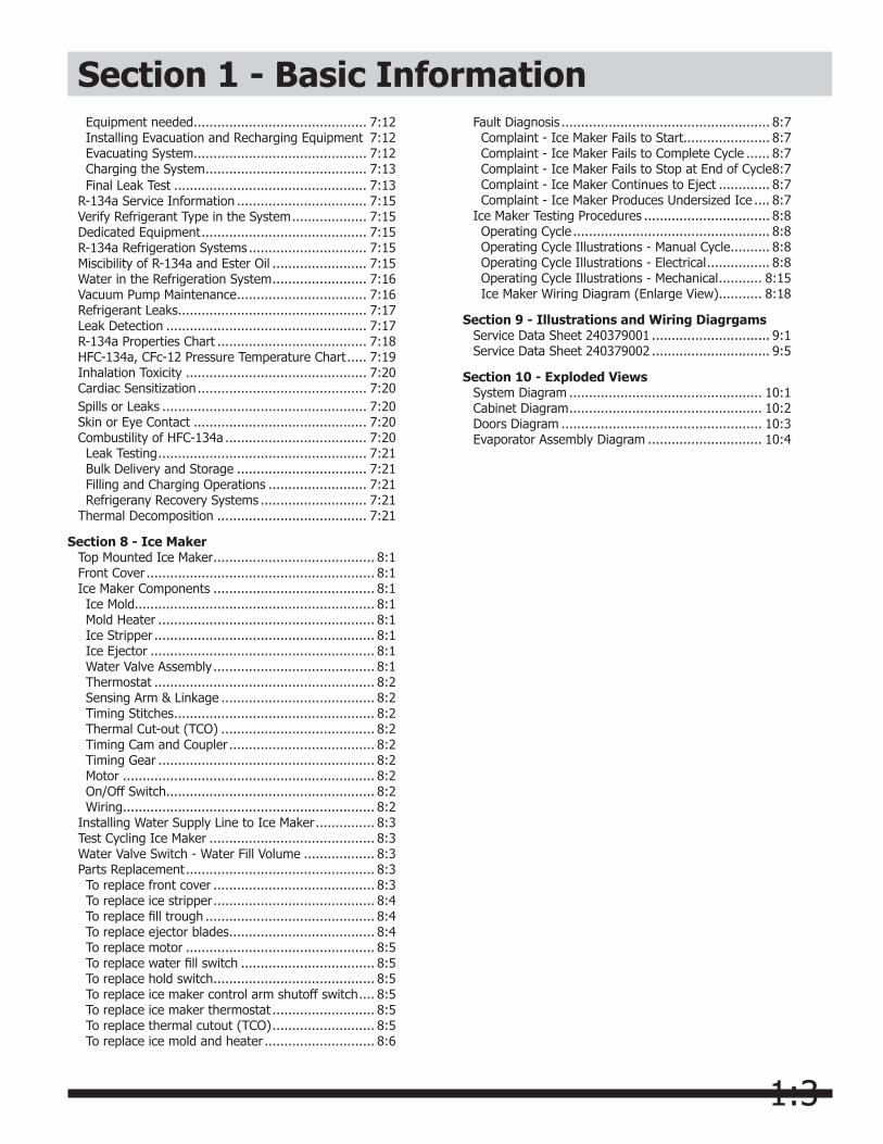
Section 1 - Basic InformationEquipment needed ............................................ 7:12Installing Evacuation and Recharging Equipment 7:12Evacuating System ............................................ 7:12Charging the System ......................................... 7:13Final Leak Test ................................................. 7:13
R-134a Service Information ................................. 7:15Verify Refrigerant Type in the System ................... 7:15Dedicated Equipment .......................................... 7:15R-134a Refrigeration Systems .............................. 7:15Miscibility of R-134a and Ester Oil ........................ 7:15Water in the Refrigeration System ........................ 7:16Vacuum Pump Maintenance ................................. 7:16Refrigerant Leaks ................................................ 7:17Leak Detection ................................................... 7:17R-134a Properties Chart ...................................... 7:18HFC-134a, CFc-12 Pressure Temperature Chart ..... 7:19Inhalation Toxicity .............................................. 7:20Cardiac Sensitization ........................................... 7:20Spills or Leaks .................................................... 7:20Skin or Eye Contact ............................................ 7:20Combustility of HFC-134a .................................... 7:20Leak Testing ..................................................... 7:21Bulk Delivery and Storage ................................. 7:21Filling and Charging Operations ......................... 7:21Refrigerany Recovery Systems ........................... 7:21
Thermal Decomposition ...................................... 7:21
Section 8 - Ice MakerTop Mounted Ice Maker ......................................... 8:1Front Cover .......................................................... 8:1Ice Maker Components ......................................... 8:1Ice Mold............................................................. 8:1Mold Heater ....................................................... 8:1Ice Stripper ........................................................ 8:1Ice Ejector ......................................................... 8:1Water Valve Assembly ......................................... 8:1Thermostat ........................................................ 8:2Sensing Arm & Linkage ....................................... 8:2Timing Stitches ................................................... 8:2Thermal Cut-out (TCO) ....................................... 8:2Timing Cam and Coupler ..................................... 8:2Timing Gear ....................................................... 8:2Motor ................................................................ 8:2On/Off Switch..................................................... 8:2Wiring ................................................................ 8:2
Installing Water Supply Line to Ice Maker ............... 8:3Test Cycling Ice Maker .......................................... 8:3Water Valve Switch - Water Fill Volume .................. 8:3Parts Replacement ................................................ 8:3To replace front cover ......................................... 8:3To replace ice stripper ......................................... 8:4To replace fill trough ........................................... 8:4To replace ejector blades ..................................... 8:4To replace motor ................................................ 8:5To replace water fill switch .................................. 8:5To replace hold switch ......................................... 8:5To replace ice maker control arm shutoff switch .... 8:5To replace ice maker thermostat .......................... 8:5To replace thermal cutout (TCO) .......................... 8:5To replace ice mold and heater ............................ 8:6
Fault Diagnosis ..................................................... 8:7Complaint - Ice Maker Fails to Start...................... 8:7Complaint - Ice Maker Fails to Complete Cycle ...... 8:7Complaint - Ice Maker Fails to Stop at End of Cycle 8:7Complaint - Ice Maker Continues to Eject ............. 8:7 Complaint - Ice Maker Produces Undersized Ice .... 8:7
Ice Maker Testing Procedures ................................ 8:8Operating Cycle .................................................. 8:8Operating Cycle Illustrations - Manual Cycle .......... 8:8Operating Cycle Illustrations - Electrical ................ 8:8Operating Cycle Illustrations - Mechanical ........... 8:15Ice Maker Wiring Diagram (Enlarge View) ........... 8:18
Section 9 - Illustrations and Wiring DiagrgamsService Data Sheet 240379001 .............................. 9:1Service Data Sheet 240379002 .............................. 9:5
Section 10 - Exploded ViewsSystem Diagram ................................................. 10:1Cabinet Diagram ................................................. 10:2Doors Diagram ................................................... 10:3Evaporator Assembly Diagram ............................. 10:4
2:1
WARNINGWARNING indicates a potentially hazardous situation which, if not avoided, could result in death or serious injury.
IMPORTANTIMPORTANT indicates installation, operation or maintenance information which is important but not hazard-related.
DANGERDANGER indicates an imminently hazardous situation which, if not avoided, will result in death or serious injury.
Definitions This is the safety alert symbol. It is used to alert you to potential personal injury hazards. Obey all safety messages that follow this symbol to avoid possible injury or death.
CAUTIONCAUTION indicates a potentially hazardous situation which, if not avoided, may result in minor or moderate injury.
Section 2 - Important Safety Instructions
For your Safety • DO NOT store or use gasoline, or other flammable
liquids in the vicinity of this or any other appliance. Read product labels for warnings regarding flammability and other hazards.
• DO NOT operate the refrigerator in the presence of explosive fumes.
• Avoid contact with any moving parts of automatic ice maker.
• Remove all staples from the carton. Staples can cause severe cuts, and also destroy finishes if they come in contact with other appliances or furniture.
WARNINGPlease read all instructions before using this refrigerator.
Doors Handles are secure and tight
Door seals completely to cabinet on all sides
Freezer door is level across the top
Leveling Refrigerator is level, side-to-side and tilted
1/4” (6mm) front-to-back
Toe grille is properly attached to refrigerator
Cabinet is setting solid on all corners
Electrical Power House power turned on
Refrigerator plugged in
Ice Maker House water supply connected to refrigerator
No water leaks present at all connections - recheck in 24 hours
Ice maker is turned ON
Ice & water dispenser operates correctly
Front filter must be flush with filter housing (select models)
Final Checks Shipping material removed
Fresh food and freezer temperatures set
Crisper humidity controls set
Registration card sent in
Installation Checklist
2:2
Section 2 - Important Safety Instructions
Electrical information • The refrigerator must be plugged into its
own dedicated 115 Volt, 60 Hz., 15 Amp, AC only electrical outlet. The power cord of the appliance is equipped with a three-prong grounding plug for your protection against electrical shock hazards. It must be plugged directly into a properly grounded three prong receptacle. The receptacle must be installed in accordance with local codes and ordinances. Consult a qualified electrician. Avoid connecting refrigerator to a Ground
WARNINGThese guidelines must be followed to ensure that safety mechanisms in this refrigerator will operate properly.
IMPORTANTPressing and holding the On/Off button for three (3) seconds, located on the left side of the temperature control panel (Electronic controls), or turning the Freezer and Fresh Food controls to “0” (Mechanical controls) will disable your refrigerator’s cooling system, but does not disconnect the power to the light bulb and other electrical components. To turn off power to your refrigerator you must unplug the power cord from the electrical outlet.
CAUTIONTo avoid personal injury or property damage, handle tempered glass shelves carefully. Shelves may break suddenly if nicked, scratched, or exposed to sudden temperature change.
Child SafetyDestroy or recycle the carton, plastic bags, and any exterior wrapping material immediately after the refrigerator is unpacked. Children should NEVER use these items to play. Cartons covered with rugs, bedspreads, plastic sheets or stretch wrap may become airtight chambers, and can quickly cause suffocation.
Proper Disposal of your Refrigerator or FreezerRisk of child entrapment
Child entrapment and suffocation are not problems of the past. Junked or abandoned refrigerators or freezers are still dangerous – even if they will sit for “just a few days”. If you are getting rid of your old refrigerator or freezer, please follow the instructions below to help prevent accidents.
Proper Disposal of Refrigerators/Freezers
We strongly encourage responsible appliance recycling/disposal methods. Check with your utility company or visit www.recyclemyoldfridge.com for more information on recycling your old refrigerator.
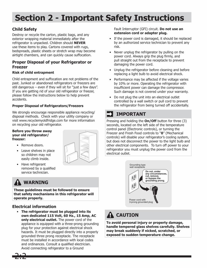
Before you throw away your old refrigerator/freezer:
• Remove doors.
• Leave shelves in place so children may not easily climb inside.
• Have refrigerant removed by a qualified service technician.
Fault Interruptor (GFI) circuit. Do not use an extension cord or adapter plug.
• If the power cord is damaged, it should be replaced by an authorized service technician to prevent any risk.
• Never unplug the refrigerator by pulling on the power cord. Always grip the plug firmly, and pull straight out from the receptacle to prevent damaging the power cord.
• Unplug the refrigerator before cleaning and before replacing a light bulb to avoid electrical shock.
• Performance may be affected if the voltage varies by 10% or more. Operating the refrigerator with insufficient power can damage the compressor. Such damage is not covered under your warranty.
• Do not plug the unit into an electrical outlet controlled by a wall switch or pull cord to prevent the refrigerator from being turned off accidentally.

2:3
UncratingUncrating instructions are clearly printed on the shipping carton. Under no circumstances should a refrigerator be uncrated until these instructions have been read.
Additional handling and installation information is provided in the “Installation Tips” affixed to the refrigerator door and in the Owner’s Use & Care Manual located in one of the drawers inside the refrigerator. Pay particular attention to the information regarding hand trucking, leveling and door alignment.
Model and Serial NumberModel and Serial Numbers are found on the Serial Plate located just below the freezer compartment on the left wall of the refrigerator compartment. (See Figure A1)
Air Circulation Proper air circulation must be maintained for efficient refrigerator operation. Refer to the Owner’s Use & Care Manual for recommended clearances. Install the refrigerator out of direct sunlight and away from the range, dishwasher, or other heat sources.
Section 2 - Installation
CAUTIONDo not install the refrigerator where the temperature will drop below 60°F (15°C), or rise above 110°F (43°C) because the compressor will not be able to maintain proper temperatures.
Allow an extra ½” (12mm) on each side for ease of installation in recessed areas. If the hinge side of the unit is placed against a wall, allow a 1¾” (40mm) space between the wall and refrigerator to permit proper door swing.
Electrical InformationThe refrigerator must be plugged into its own 115 Volt, 60 Hz, AC only electrical outlet. The circuit should be protected by a 15 or 20 Amp circuit breaker or time delay type fuse.
NOTEIf voltage varies by ±10% of 115 volts, performance of the refrigerator may be affected. Operating the refrigerator with insufficient power can damage the compressor.
The refrigerator power cord is equipped with a three prong grounding plug. It must be plugged directly into a properly grounded three prong receptacle. The receptacle must be installed in accordance with local
codes and ordinances. Do not use an extension cord or an adapter plug.
Figure A1
LevelingThe refrigerator must be leveled with all bottom corners resting firmly on a solid floor. Adjust the front rollers to level the cabinet from side-to-side and front-to-rear. Keep the cabinet as low as possible for stability. Never adjust the cabinet rollers so the front is lower than the rear.
To adjust the rollers:
Open refrigerator and freezer doors.1.
Remove toe grille by pulling it straight out. (See 2. Figure A2)
Adjust front rollers by turning each roller adjusting 3. bolt with adjustable wrench, socket wrench, nutdriver or screwdriver until refrigerator is level and stable. (See Figure A3)
Rear rollers are not adjustable.4.
Figure A2
Figure A3
2:4
Section 2 - Installation
Door Removal and Reversal InstructionsThis refrigerator is equipped with reversible door hinges. An envelope containing extra plastic hole plugs is included in some models. In the event you need to remove the doors and hinges to get this unit through the door or the customer wants the doors reversed, use the procedure below. Turn the refrigerator control to OFF. Remove all food, bottles, and other items from the door. Begin with freezer door. Completely remove one door before beginning the other.
To Remove Freezer Door: (See Figure A4.)
1. Snap off hinge cover at top of refrigerator.
2. With freezer door closed, remove two hex head screws attaching upper hinge to cabinet.
3. Lift upper hinge up and off.
4. Open freezer door enough to allow it to be lifted off center hinge.Set door aside for reassembly later.
5. Remove hole plugs from opposite side of cabinet top and place in holes where hinge was mounted.
NOTE
Save hinge and screws for reassembly later.
Figure A4
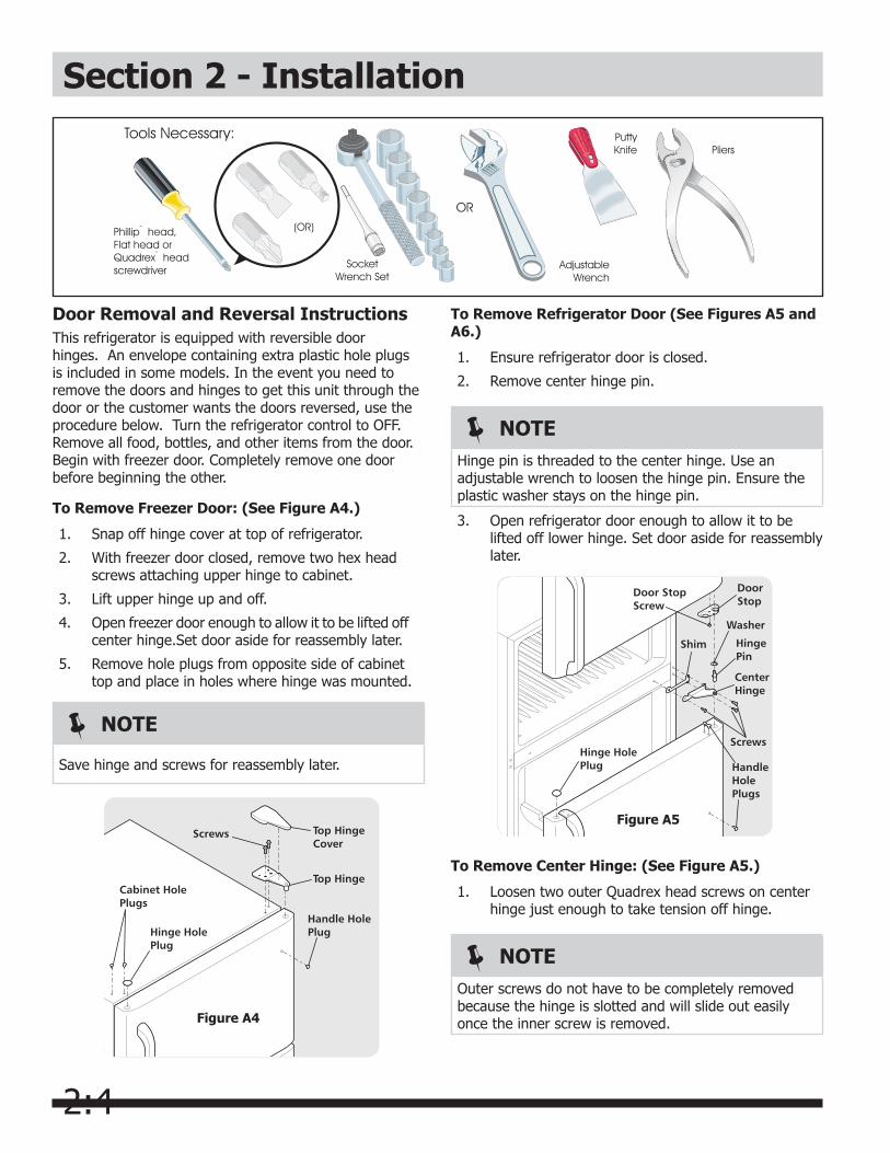
To Remove Refrigerator Door (See Figures A5 and A6.)
1. Ensure refrigerator door is closed.
2. Remove center hinge pin.
NOTEHinge pin is threaded to the center hinge. Use an adjustable wrench to loosen the hinge pin. Ensure the plastic washer stays on the hinge pin.
3. Open refrigerator door enough to allow it to be lifted off lower hinge. Set door aside for reassembly later.
Figure A5
To Remove Center Hinge: (See Figure A5.)
1. Loosen two outer Quadrex head screws on center hinge just enough to take tension off hinge.
NOTEOuter screws do not have to be completely removed because the hinge is slotted and will slide out easily once the inner screw is removed.
2:5
Section 2 - Installation
NOTESave the hinge, hinge pin, washer and shim for reassembly later.
2. Remove inner Quadrex head screw on center hinge.
3. Slide out hinge and shim. Tighten down two outer screws you loosened in step 1.
4. Put inner screw back in and tighten down.
To Remove Lower Hinge: (See Figure A6.)
1. Remove toe grille from front of refrigerator by pulling straight forward.
2. Remove three hex head screws holding lower hinge to cabinet.
3. Put two outer screws back in holes where hinge was and tighten down. Inner screw hole will stay empty.
Figure A6
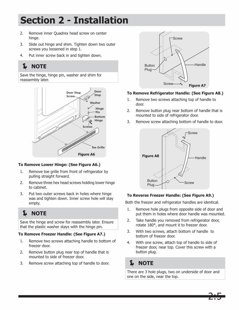
To Remove Freezer Handle: (See Figure A7.)
1. Remove two screws attaching handle to bottom of freezer door.
2. Remove button plug near top of handle that is mounted to side of freezer door.
3. Remove screw attaching top of handle to door.
NOTESave the hinge and screw for reassembly later. Ensure that the plastic washer stays with the hinge pin.
Figure A7
To Remove Refrigerator Handle: (See Figure A8.)
1. Remove two screws attaching top of handle to door.
2. Remove button plug near bottom of handle that is mounted to side of refrigerator door.
3. Remove screw attaching bottom of handle to door.
To Reverse Freezer Handle: (See Figure A9.)
Both the freezer and refrigerator handles are identical.
1. Remove hole plugs from opposite side of door and put them in holes where door handle was mounted.
2. Take handle you removed from refrigerator door, rotate 180°, and mount it to freezer door.
3. With two screws, attach bottom of handle to bottom of freezer door.
4. With one screw, attach top of handle to side of freezer door, near top. Cover this screw with a button plug.
Figure A8
NOTEThere are 3 hole plugs, two on underside of door and one on the side, near the top.
2:6
Section 2 - Installation
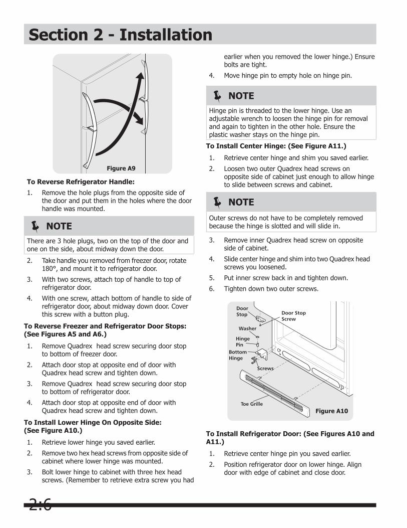
To Reverse Refrigerator Handle:
1. Remove the hole plugs from the opposite side of the door and put them in the holes where the door handle was mounted.
Figure A9
NOTEThere are 3 hole plugs, two on the top of the door and one on the side, about midway down the door.
2. Take handle you removed from freezer door, rotate 180°, and mount it to refrigerator door.
3. With two screws, attach top of handle to top of refrigerator door.
4. With one screw, attach bottom of handle to side of refrigerator door, about midway down door. Cover this screw with a button plug.
To Reverse Freezer and Refrigerator Door Stops: (See Figures A5 and A6.)
1. Remove Quadrex head screw securing door stop to bottom of freezer door.
2. Attach door stop at opposite end of door with Quadrex head screw and tighten down.
3. Remove Quadrex head screw securing door stop to bottom of refrigerator door.
4. Attach door stop at opposite end of door with Quadrex head screw and tighten down.
To Install Lower Hinge On Opposite Side: (See Figure A10.)
1. Retrieve lower hinge you saved earlier.
2. Remove two hex head screws from opposite side of cabinet where lower hinge was mounted.
3. Bolt lower hinge to cabinet with three hex head screws. (Remember to retrieve extra screw you had
earlier when you removed the lower hinge.) Ensure bolts are tight.
4. Move hinge pin to empty hole on hinge pin.
NOTEHinge pin is threaded to the lower hinge. Use an adjustable wrench to loosen the hinge pin for removal and again to tighten in the other hole. Ensure the plastic washer stays on the hinge pin.
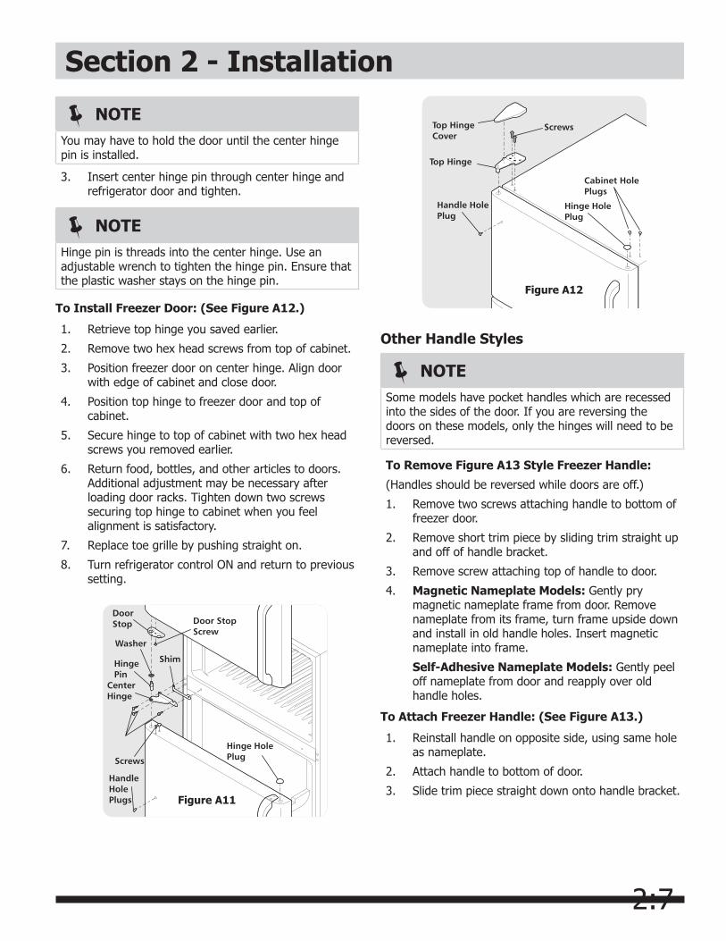
To Install Center Hinge: (See Figure A11.)
1. Retrieve center hinge and shim you saved earlier.
2. Loosen two outer Quadrex head screws on opposite side of cabinet just enough to allow hinge to slide between screws and cabinet.
NOTE
Outer screws do not have to be completely removed because the hinge is slotted and will slide in.
3. Remove inner Quadrex head screw on opposite side of cabinet.
4. Slide center hinge and shim into two Quadrex head screws you loosened.
5. Put inner screw back in and tighten down.
6. Tighten down two outer screws.
Figure A10
To Install Refrigerator Door: (See Figures A10 and A11.)
1. Retrieve center hinge pin you saved earlier.
2. Position refrigerator door on lower hinge. Align door with edge of cabinet and close door.
2:7
Section 2 - Installation
3. Insert center hinge pin through center hinge and refrigerator door and tighten.
NOTEYou may have to hold the door until the center hinge pin is installed.
NOTEHinge pin is threads into the center hinge. Use an adjustable wrench to tighten the hinge pin. Ensure that the plastic washer stays on the hinge pin.
To Install Freezer Door: (See Figure A12.)
1. Retrieve top hinge you saved earlier.
2. Remove two hex head screws from top of cabinet.
3. Position freezer door on center hinge. Align door with edge of cabinet and close door.
4. Position top hinge to freezer door and top of cabinet.
5. Secure hinge to top of cabinet with two hex head screws you removed earlier.
6. Return food, bottles, and other articles to doors. Additional adjustment may be necessary after loading door racks. Tighten down two screws securing top hinge to cabinet when you feel alignment is satisfactory.
7. Replace toe grille by pushing straight on.
8. Turn refrigerator control ON and return to previous setting.
Figure A11
Figure A12
Other Handle Styles
NOTESome models have pocket handles which are recessed into the sides of the door. If you are reversing the doors on these models, only the hinges will need to be reversed.
To Remove Figure A13 Style Freezer Handle:
(Handles should be reversed while doors are off.)
1. Remove two screws attaching handle to bottom of freezer door.
2. Remove short trim piece by sliding trim straight up and off of handle bracket.
3. Remove screw attaching top of handle to door.
4. Magnetic Nameplate Models: Gently pry magnetic nameplate frame from door. Remove nameplate from its frame, turn frame upside down and install in old handle holes. Insert magnetic nameplate into frame.
Self-Adhesive Nameplate Models: Gently peel off nameplate from door and reapply over old handle holes.
To Attach Freezer Handle: (See Figure A13.)
1. Reinstall handle on opposite side, using same hole as nameplate.
2. Attach handle to bottom of door.
3. Slide trim piece straight down onto handle bracket.

2:8
Section 2 - Installation
Figure A13
To Remove Figure A14 Style Freezer Handle:
(Handles should be reversed while doors are off.)
1. Remove two screws attaching handle to bottom of freezer door.
2. Swing bottom of handle away from door and slide straight up and off dovetail button.
3. Remove screw and dovetail button and install on other side, using same holes as nameplate.
4. Magnetic Nameplate Models: Gently pry magnetic nameplate frame from door. Remove nameplate from its frame, turn frame upside down and install in old handle holes. Insert magnetic nameplate into frame.
Self-Adhesive Nameplate Models: Use putty knife to gently peel off nameplate from door and reapply over old handle holes.
To Attach Freezer Handle: (See Figure A14.)
1. Start with handle offset away from door. Place top of handle over dovetail button, swing handle into upright position and pull downward, locking it into place.
2. Secure bottom of handle with two screws removed earlier.
Figure A14
TRIM REMOVAL (Full-Length Trim Models Only)In some models, the refrigerator door has a full length trim piece which continues from the bottom of the handle to the bottom of the door. The top of the trim attaches to the handle bracket (Figure A15) or fits around the base of the handle (Figure A16). An adhesive trim lock is positioned about halfway down. The bottom of the trim is held in place by either an adhesive trim lock, or a trim lock with two prongs inserted into a hole on the face of the door.
To Remove Trim:
1. Remove trim by gently pulling trim lock areas out and away from door.
2. When trim is free from door, slide trim straight down and away from base of handle.
NOTEFor models with short handle trim, remove by sliding trim straight down and off handle bracket.
To Remove Refrigerator Handle: (Handles should be removed while doors are off.)
Figure A15 Style Handles
1. Remove two screws attaching handle to top of refrigerator door.
2. Remove screw attaching bottom of handle to door.
Figure A16 Style Handles
1. Remove two screws attaching handle to top of refrigerator door.
2. Swing top of handle away from door and slide handle down and off dovetail button.
3. Remove screw and dovetail button and install on other side, moving hole plugs from corresponding holes to opposite side.
Figure A15
2:9
Section 2 - InstallationRemoving Stainless Steel Doors and Handles
To Attach Refrigerator Handle:
Figure A15 Style Handles
1. Secure bottom of handle with screws.
2. Secure top of handles with screws.
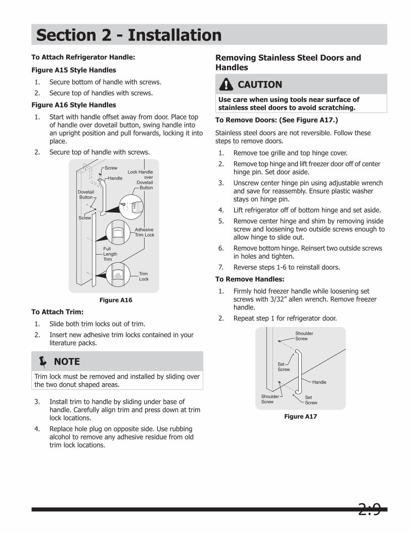
Figure A16 Style Handles
1. Start with handle offset away from door. Place top of handle over dovetail button, swing handle into an upright position and pull forwards, locking it into place.
2. Secure top of handle with screws.
Figure A16
NOTETrim lock must be removed and installed by sliding over the two donut shaped areas.
To Attach Trim:
1. Slide both trim locks out of trim.
2. Insert new adhesive trim locks contained in your literature packs.
3. Install trim to handle by sliding under base of handle. Carefully align trim and press down at trim lock locations.
4. Replace hole plug on opposite side. Use rubbing alcohol to remove any adhesive residue from old trim lock locations.
CAUTIONUse care when using tools near surface of stainless steel doors to avoid scratching.
To Remove Doors: (See Figure A17.)
Stainless steel doors are not reversible. Follow these steps to remove doors.
1. Remove toe grille and top hinge cover.
2. Remove top hinge and lift freezer door off of center hinge pin. Set door aside.
3. Unscrew center hinge pin using adjustable wrench and save for reassembly. Ensure plastic washer stays on hinge pin.
4. Lift refrigerator off of bottom hinge and set aside.
5. Remove center hinge and shim by removing inside screw and loosening two outside screws enough to allow hinge to slide out.
6. Remove bottom hinge. Reinsert two outside screws in holes and tighten.
7. Reverse steps 1-6 to reinstall doors.
To Remove Handles:
1. Firmly hold freezer handle while loosening set screws with 3/32” allen wrench. Remove freezer handle.
2. Repeat step 1 for refrigerator door.
Figure A17
2:10
Section 2 - InstallationDoor Alignment The center hinge on all models, and the lower hinge on models without a Toe Grille, have mounting holes with little or no clearance. Alignment adjustments are very limited with the exception of adding or removing shims or spacers.
There may be instances when the door gaskets will not form a seal on the hinge side of the door immediately after reversing the door swing, particularly when gasket temperature is below 76°F, or when the refrigerator is in operation.That portion of the gasket now on the hinge side of the doors (formerly on handle side) has a slightly compressed accordion fold section that has set in place. The accordion folds must be relaxed for the gasket to form a seal. The gasket will relax (expand) and seal in sufficient time.
To accelerate the expansion of the accordion fold section, open the doors and pull outward on the gaskets progressively from top to bottom of door. Close doors and check for a seal. Repeat the procedure if necessary. If gaskets do not magnetically form a complete seal within several minutes, warm the gaskets using a 150 watt lamp or suitable heating device.
CAUTION
Be careful not to overheat gasket.
With the doors closed, direct the heat on the entire length of the gasket until a seal is formed.
CAUTIONTo avoid property damage:•Coppertubingisrecommendedforthewater
supply line. Water supply tubing made of 1/4” plastic is not recommended since it greatly increases the potential for water leaks. Manufacturer will not be responsible for any damage if plastic tubing is used for supply line.
•DONOTinstallwatersupplytubinginareaswhere temperatures fall below freezing.
•Chemicalsfromamalfunctioningsoftenercan damage the ice maker. If the ice maker is connected to soft water, ensure that the softener is maintained and working properly.
WARNINGTo avoid electric shock, which can cause death or severe personal injury, disconnect the refrigerator from electrical power before connecting a water supply line to the refrigerator.
NOTEA kit is available from your dealer that provides all materials for a water supply installation, including 25 feet of copper tubing and full instructions.
What you will need: • A cold water line with pressure of 30-100 psi.
(System is to be supplied with cold water only.)
• Copper tubing with ¼ inch (6.4mm) Outside Diameter (OD). Length for this tubing is the distance from the rear of the refrigerator to your household water supply line plus seven (7) feet (2.1 meters).
• A shut-off valve for the connection between your household water line and the refrigerator supply line.
Do not use a self-piercing shut-off valve.
• A compression nut and ferrule (sleeve) for the water supply connection at the rear of your refrigerator.
Connecting the Water Supply
2:11
Section 2 - Installation
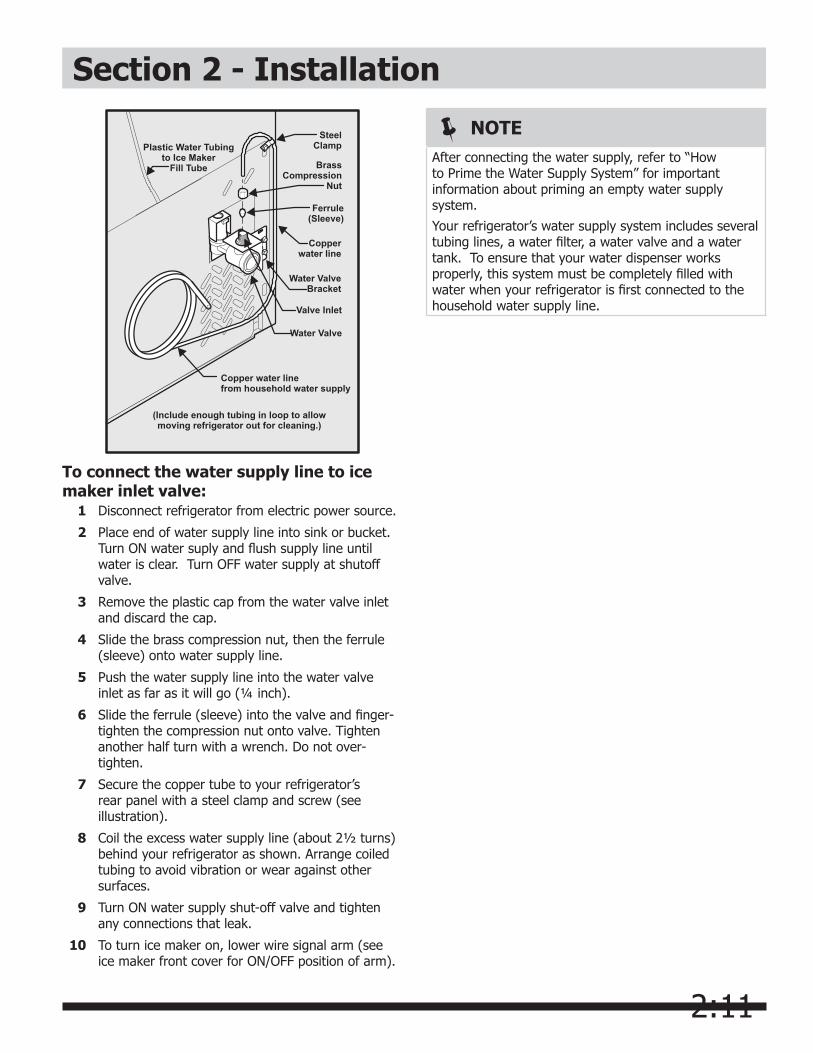
Copper water linefrom household water supply
(Include enough tubing in loop to allowmoving refrigerator out for cleaning.)
Ferrule(Sleeve)
Copperwater line
Water Valve
Valve Inlet
Water ValveBracket
SteelClampPlastic Water Tubing
to Ice MakerFill Tube Brass
CompressionNut
To connect the water supply line to ice maker inlet valve: 1 Disconnect refrigerator from electric power source.
2 Place end of water supply line into sink or bucket. Turn ON water suply and flush supply line until water is clear. Turn OFF water supply at shutoff valve.
3 Remove the plastic cap from the water valve inlet and discard the cap.
4 Slide the brass compression nut, then the ferrule (sleeve) onto water supply line.
5 Push the water supply line into the water valve inlet as far as it will go (¼ inch).
6 Slide the ferrule (sleeve) into the valve and finger-tighten the compression nut onto valve. Tighten another half turn with a wrench. Do not over-tighten.
7 Secure the copper tube to your refrigerator’s rear panel with a steel clamp and screw (see illustration).
8 Coil the excess water supply line (about 2½ turns) behind your refrigerator as shown. Arrange coiled tubing to avoid vibration or wear against other surfaces.
9 Turn ON water supply shut-off valve and tighten any connections that leak.
10 To turn ice maker on, lower wire signal arm (see ice maker front cover for ON/OFF position of arm).
NOTEAfter connecting the water supply, refer to “How to Prime the Water Supply System” for important information about priming an empty water supply system.
Your refrigerator’s water supply system includes several tubing lines, a water filter, a water valve and a water tank. To ensure that your water dispenser works properly, this system must be completely filled with water when your refrigerator is first connected to the household water supply line.
3:1
Section 3 - Refrigerator Operation
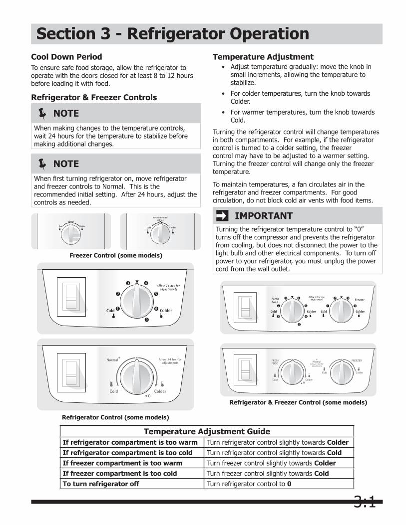
IMPORTANTTurning the refrigerator temperature control to “0” turns off the compressor and prevents the refrigerator from cooling, but does not disconnect the power to the light bulb and other electrical components. To turn off power to your refrigerator, you must unplug the power cord from the wall outlet.
NOTEWhen making changes to the temperature controls, wait 24 hours for the temperature to stabilize before making additional changes.
NOTEWhen first turning refrigerator on, move refrigerator and freezer controls to Normal. This is the recommended initial setting. After 24 hours, adjust the controls as needed.
Temperature Adjustment GuideIf refrigerator compartment is too warm Turn refrigerator control slightly towards ColderIf refrigerator compartment is too cold Turn refrigerator control slightly towards ColdIf freezer compartment is too warm Turn freezer control slightly towards ColderIf freezer compartment is too cold Turn freezer control slightly towards ColdTo turn refrigerator off Turn refrigerator control to 0
Refrigerator Control (some models)
Freezer Control (some models)
Refrigerator & Freezer Control (some models)
Temperature Adjustment • Adjust temperature gradually: move the knob in
small increments, allowing the temperature to stabilize.
• For colder temperatures, turn the knob towards Colder.
• For warmer temperatures, turn the knob towards Cold.
Turning the refrigerator control will change temperatures in both compartments. For example, if the refrigerator control is turned to a colder setting, the freezer control may have to be adjusted to a warmer setting. Turning the freezer control will change only the freezer temperature.
To maintain temperatures, a fan circulates air in the refrigerator and freezer compartments. For good circulation, do not block cold air vents with food items.
Cool Down PeriodTo ensure safe food storage, allow the refrigerator to operate with the doors closed for at least 8 to 12 hours before loading it with food.
Refrigerator & Freezer Controls
3:2
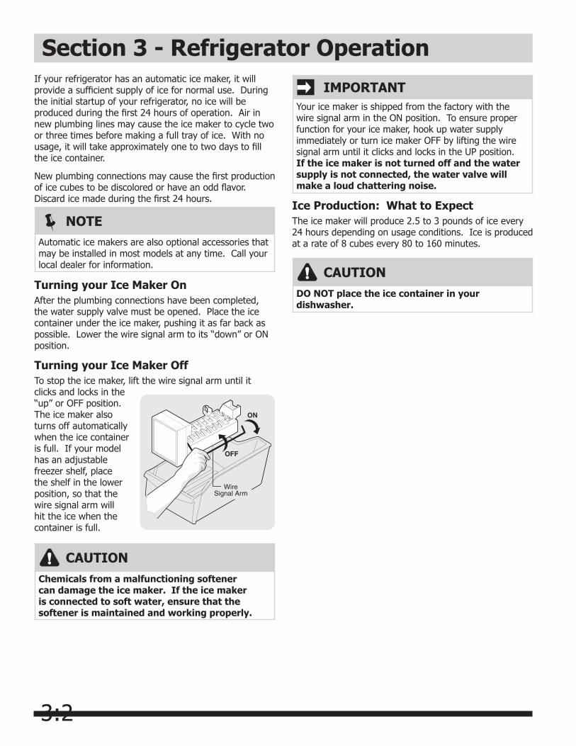
IMPORTANTYour ice maker is shipped from the factory with the wire signal arm in the ON position. To ensure proper function for your ice maker, hook up water supply immediately or turn ice maker OFF by lifting the wire signal arm until it clicks and locks in the UP position. If the ice maker is not turned off and the water supply is not connected, the water valve will make a loud chattering noise.
Section 3 - Refrigerator OperationIf your refrigerator has an automatic ice maker, it will provide a sufficient supply of ice for normal use. During the initial startup of your refrigerator, no ice will be produced during the first 24 hours of operation. Air in new plumbing lines may cause the ice maker to cycle two or three times before making a full tray of ice. With no usage, it will take approximately one to two days to fill the ice container.
New plumbing connections may cause the first production of ice cubes to be discolored or have an odd flavor. Discard ice made during the first 24 hours.
Turning your Ice Maker OnAfter the plumbing connections have been completed, the water supply valve must be opened. Place the ice container under the ice maker, pushing it as far back as possible. Lower the wire signal arm to its “down” or ON position.
Turning your Ice Maker OffTo stop the ice maker, lift the wire signal arm until it clicks and locks in the “up” or OFF position. The ice maker also turns off automatically when the ice container is full. If your model has an adjustable freezer shelf, place the shelf in the lower position, so that the wire signal arm will hit the ice when the container is full.
NOTEAutomatic ice makers are also optional accessories that may be installed in most models at any time. Call your local dealer for information.
CAUTIONChemicals from a malfunctioning softener can damage the ice maker. If the ice maker is connected to soft water, ensure that the softener is maintained and working properly.
CAUTIONDO NOT place the ice container in your dishwasher.
Ice Production: What to ExpectThe ice maker will produce 2.5 to 3 pounds of ice every 24 hours depending on usage conditions. Ice is produced at a rate of 8 cubes every 80 to 160 minutes.
3:3
NOTERigid foam insulation is very energy efficient, but is not a sound insulator.
Understanding the Sounds you may Hear
Your new, high-efficiency refrigerator may introduce unfamiliar sounds. These sounds normally indicate your refrigerator is operating correctly. Some surfaces on floors, walls, and kitchen cabinets may make these sounds more noticeable.
IMPORTANTDuring the automatic defrost cycle, you may notice a red glow in the vents on the back wall of your freezer compartment. This is normal during the defrost cycle.
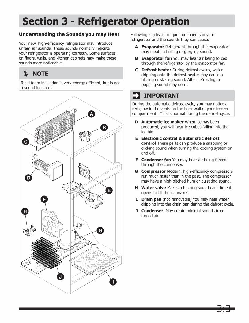
Following is a list of major components in your refrigerator and the sounds they can cause:
A Evaporator Refrigerant through the evaporator may create a boiling or gurgling sound.
B Evaporator fan You may hear air being forced through the refrigerator by the evaporator fan.
C Defrost heater During defrost cycles, water dripping onto the defrost heater may cause a hissing or sizzling sound. After defrosting, a popping sound may occur.
D Automatic ice maker When ice has been produced, you will hear ice cubes falling into the ice bin.
E Electronic control & automatic defrost control These parts can produce a snapping or clicking sound when turning the cooling system on and off.
F Condenser fan You may hear air being forced through the condenser.
G Compressor Modern, high-efficiency compressors run much faster than in the past. The compressor may have a high-pitched hum or pulsating sound.
H Water valve Makes a buzzing sound each time it opens to fill the ice maker.
I Drain pan (not removable) You may hear water dripping into the drain pan during the defrost cycle.
J Condenser May create minimal sounds from forced air.
Section 3 - Refrigerator Operation
3:4
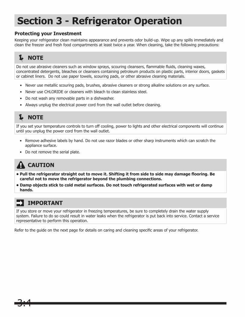
IMPORTANTIf you store or move your refrigerator in freezing temperatures, be sure to completely drain the water supply system. Failure to do so could result in water leaks when the refrigerator is put back into service. Contact a service representative to perform this operation.
CAUTION•Pulltherefrigeratorstraightouttomoveit.Shiftingitfromsidetosidemaydamageflooring.Be
careful not to move the refrigerator beyond the plumbing connections.•Dampobjectssticktocoldmetalsurfaces.Donottouchrefrigeratedsurfaceswithwetordamp
hands.
NOTEIf you set your temperature controls to turn off cooling, power to lights and other electrical components will continue until you unplug the power cord from the wall outlet.
NOTEDo not use abrasive cleaners such as window sprays, scouring cleansers, flammable fluids, cleaning waxes, concentrated detergents, bleaches or cleansers containing petroleum products on plastic parts, interior doors, gaskets or cabinet liners. Do not use paper towels, scouring pads, or other abrasive cleaning materials.
Protecting your InvestmentKeeping your refrigerator clean maintains appearance and prevents odor build-up. Wipe up any spills immediately and clean the freezer and fresh food compartments at least twice a year. When cleaning, take the following precautions:
• Remove adhesive labels by hand. Do not use razor blades or other sharp instruments which can scratch the appliance surface.
• Do not remove the serial plate.
Refer to the guide on the next page for details on caring and cleaning specific areas of your refrigerator.
• Never use metallic scouring pads, brushes, abrasive cleaners or strong alkaline solutions on any surface.
• Never use CHLORIDE or cleaners with bleach to clean stainless steel.
• Do not wash any removable parts in a dishwasher.
• Always unplug the electrical power cord from the wall outlet before cleaning.
Section 3 - Refrigerator Operation

3:5
CAUTIONWear gloves when replacing light bulbs to avoid getting cut.
Care & Cleaning TipsPart What To Use Tips and Precautions
Interior & Door Liners
Soap and water• Baking soda and • water
Use 2 tablespoons of baking soda in 1 quart of warm water. Be sure to wring excess water out of sponge or cloth before cleaning around controls, light bulb or any electrical part.
Door Gaskets Soap and water• Wipe gaskets with a clean soft cloth.
Drawers & Bins
Soap and water• Use a soft cloth to clean drawer runners and tracks. Do not wash any removable items (bins, drawers, etc.) in dishwasher.
Glass Shelves Soap and water• Glass cleaner• Mild liquid sprays•
Allow glass to warm to room temperature before immersing in warm water.
Toe Grille Soap and water• Mild liquid sprays• Vacuum attachment•
Vacuum dust from front of toe grille. Remove toe grille (see Installation Instructions). Vacuum backside and wipe with sudsy cloth or sponge. Rinse and dry.
Exterior & Handles
Soap and water• Non Abrasive Glass • Cleaner
Do not use commercial household cleaners containing ammonia, bleach or alcohol to clean handles. Use a soft cloth to clean smooth handles. DO NOT use a dry cloth to clean smooth doors.
Exterior & Handles(Stainless Steel Models Only)
Soap and water•
Stainless Steel • Cleaners
Never use CHLORIDE or cleaners with bleach to clean stainless steel.
Clean stainless steel front and handles with non-abrasive soapy water and a dish-cloth. Rinse with clean water and a soft cloth. Use a non-abrasive stainless steel cleaner. These cleaners can be purchased at most home improvement or major department stores. Always follow manufacturer’s instructions. Do not use household cleaners containing ammonia or bleach.
NOTE: Always clean, wipe and dry with the grain to prevent scratching. Wash the rest of the cabinet with warm water and mild liquid detergent. Rinse well, and wipe dry with a clean soft cloth.
Section 3 - Refrigerator Operation
Replacing Light Bulbs
1 Unplug refrigerator.
2 Wear gloves as protection against possible broken glass.
3 Remove light cover, if necessary.
4 Unscrew and replace old bulb with an appliance bulb of the same wattage.
5 Replace light cover, if necessary.
6 Remember to plug the refrigerator back in.
3:6
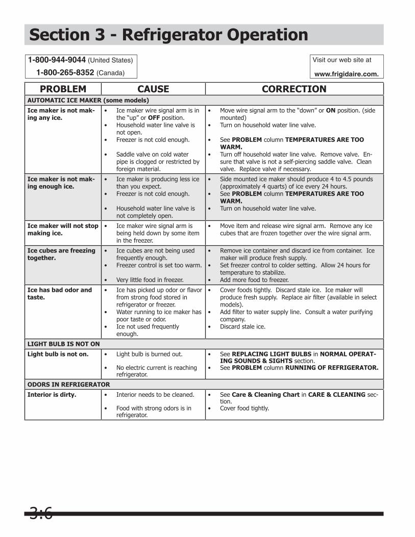
Section 3 - Refrigerator OperationVisit our web site at
www.frigidaire.com.
1-800-944-9044 (United States)
1-800-265-8352 (Canada)
PROBLEM CAUSE CORRECTIONAUTOMATIC ICE MAKER (some models)
Ice maker is not mak-ing any ice.
Ice maker wire signal arm is in • the “up” or OFF position.Household water line valve is • not open.Freezer is not cold enough.•
Saddle valve on cold water • pipe is clogged or restricted by foreign material.
Move wire signal arm to the “down” or • ON position. (side mounted)Turn on household water line valve.•
See • PROBLEM column TEMPERATURES ARE TOO WARM.Turn off household water line valve. Remove valve. En-• sure that valve is not a self-piercing saddle valve. Clean valve. Replace valve if necessary.
Ice maker is not mak-ing enough ice.
Ice maker is producing less ice • than you expect.Freezer is not cold enough.•
Household water line valve is • not completely open.
Side mounted ice maker should produce 4 to 4.5 pounds • (approximately 4 quarts) of ice every 24 hours. See • PROBLEM column TEMPERATURES ARE TOO WARM.Turn on household water line valve.•
Ice maker will not stop making ice.
Ice maker wire signal arm is • being held down by some item in the freezer.
Move item and release wire signal arm. Remove any ice • cubes that are frozen together over the wire signal arm.
Ice cubes are freezing together.
Ice cubes are not being used • frequently enough.Freezer control is set too warm.•
Very little food in freezer.•
Remove ice container and discard ice from container. Ice • maker will produce fresh supply.Set freezer control to colder setting. Allow 24 hours for • temperature to stabilize.Add more food to freezer.•
Ice has bad odor and taste.
Ice has picked up odor or flavor • from strong food stored in refrigerator or freezer.Water running to ice maker has • poor taste or odor.Ice not used frequently • enough.
Cover foods tightly. Discard stale ice. Ice maker will • produce fresh supply. Replace air filter (available in select models).Add filter to water supply line. Consult a water purifying • company.Discard stale ice.•
LIGHT BULB IS NOT ON
Light bulb is not on. Light bulb is burned out.•
No electric current is reaching • refrigerator.
See • REPLACING LIGHT BULBS in NORMAL OPERAT-ING SOUNDS & SIGHTS section.See • PROBLEM column RUNNING OF REFRIGERATOR.
ODORS IN REFRIGERATOR
Interior is dirty. Interior needs to be cleaned.•
Food with strong odors is in • refrigerator.
See • Care & Cleaning Chart in CARE & CLEANING sec-tion.Cover food tightly.•
3:7
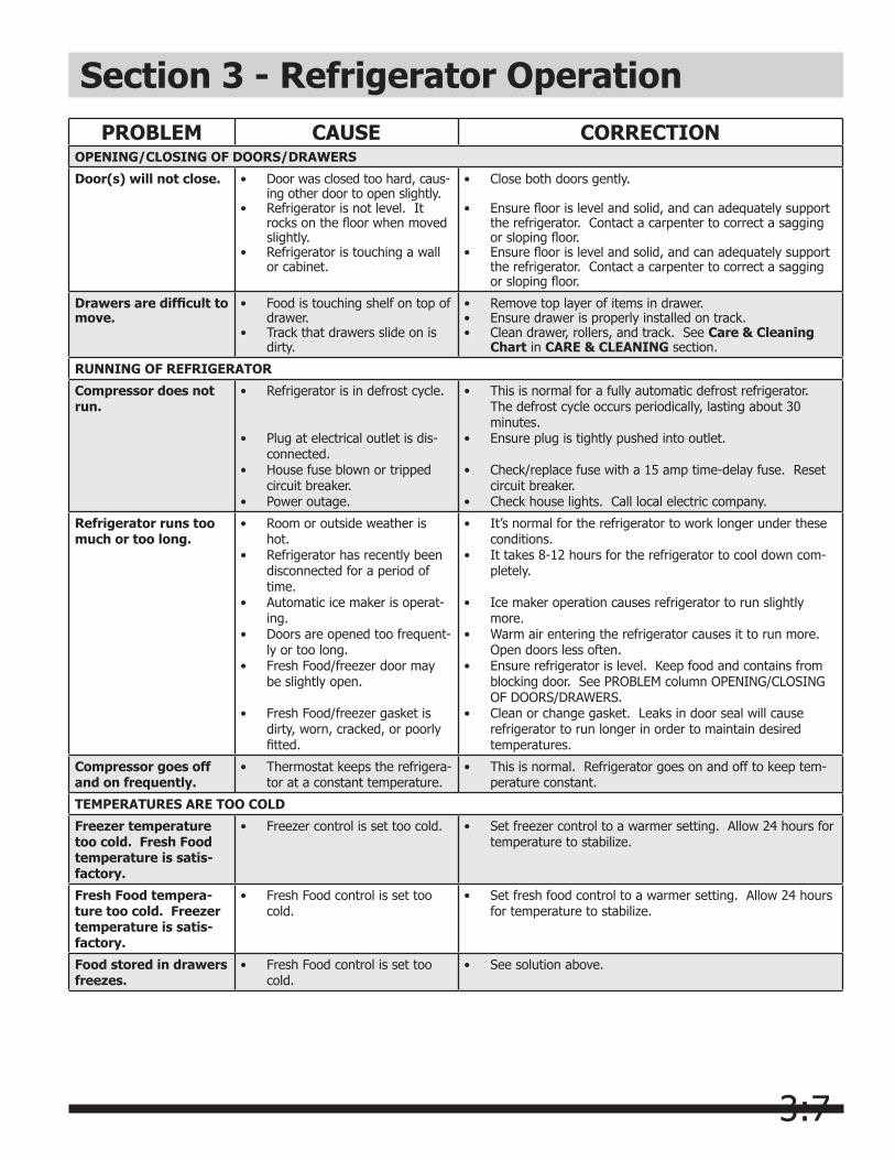
Section 3 - Refrigerator OperationPROBLEM CAUSE CORRECTION
OPENING/CLOSING OF DOORS/DRAWERS
Door(s) will not close. Door was closed too hard, caus-• ing other door to open slightly.Refrigerator is not level. It • rocks on the floor when moved slightly.Refrigerator is touching a wall • or cabinet.
Close both doors gently.•
Ensure floor is level and solid, and can adequately support • the refrigerator. Contact a carpenter to correct a sagging or sloping floor.Ensure floor is level and solid, and can adequately support • the refrigerator. Contact a carpenter to correct a sagging or sloping floor.
Drawersaredifficulttomove.
Food is touching shelf on top of • drawer.Track that drawers slide on is • dirty.
Remove top layer of items in drawer.• Ensure drawer is properly installed on track.• Clean drawer, rollers, and track. See • Care & Cleaning Chart in CARE & CLEANING section.
RUNNING OF REFRIGERATOR
Compressor does not run.
Refrigerator is in defrost cycle.•
Plug at electrical outlet is dis-• connected.House fuse blown or tripped • circuit breaker.Power outage.•
This is normal for a fully automatic defrost refrigerator. • The defrost cycle occurs periodically, lasting about 30 minutes.Ensure plug is tightly pushed into outlet.•
Check/replace fuse with a 15 amp time-delay fuse. Reset • circuit breaker.Check house lights. Call local electric company.•
Refrigerator runs too much or too long.
Room or outside weather is • hot.Refrigerator has recently been • disconnected for a period of time.Automatic ice maker is operat-• ing.Doors are opened too frequent-• ly or too long.Fresh Food/freezer door may • be slightly open.
Fresh Food/freezer gasket is • dirty, worn, cracked, or poorly fitted.
It’s normal for the refrigerator to work longer under these • conditions.It takes 8-12 hours for the refrigerator to cool down com-• pletely.
Ice maker operation causes refrigerator to run slightly • more.Warm air entering the refrigerator causes it to run more. • Open doors less often.Ensure refrigerator is level. Keep food and contains from • blocking door. See PROBLEM column OPENING/CLOSING OF DOORS/DRAWERS.Clean or change gasket. Leaks in door seal will cause • refrigerator to run longer in order to maintain desired temperatures.
Compressor goes off and on frequently.
Thermostat keeps the refrigera-• tor at a constant temperature.
This is normal. Refrigerator goes on and off to keep tem-• perature constant.
TEMPERATURES ARE TOO COLD
Freezer temperature too cold. Fresh Food temperature is satis-factory.
Freezer control is set too cold.• Set freezer control to a warmer setting. Allow 24 hours for • temperature to stabilize.
Fresh Food tempera-ture too cold. Freezer temperature is satis-factory.
Fresh Food control is set too • cold.
Set fresh food control to a warmer setting. Allow 24 hours • for temperature to stabilize.
Food stored in drawers freezes.
Fresh Food control is set too • cold.
See solution above.•
3:8
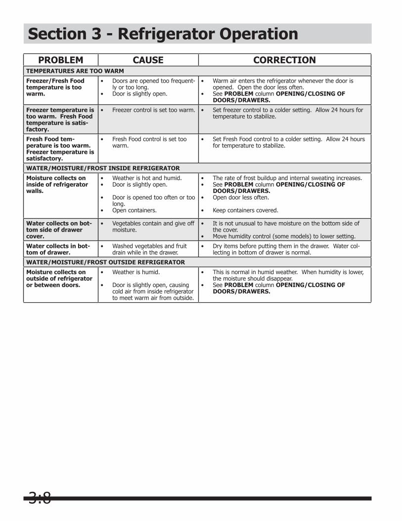
Section 3 - Refrigerator OperationPROBLEM CAUSE CORRECTION
TEMPERATURES ARE TOO WARM
Freezer/Fresh Food temperature is too warm.
Doors are opened too frequent-• ly or too long.Door is slightly open.•
Warm air enters the refrigerator whenever the door is • opened. Open the door less often.See • PROBLEM column OPENING/CLOSING OF DOORS/DRAWERS.
Freezer temperature is too warm. Fresh Food temperature is satis-factory.
Freezer control is set too warm.• Set freezer control to a colder setting. Allow 24 hours for • temperature to stabilize.
Fresh Food tem-perature is too warm. Freezer temperature is satisfactory.
Fresh Food control is set too • warm.
Set Fresh Food control to a colder setting. Allow 24 hours • for temperature to stabilize.
WATER/MOISTURE/FROST INSIDE REFRIGERATOR
Moisture collects on inside of refrigerator walls.
Weather is hot and humid.• Door is slightly open.•
Door is opened too often or too • long.Open containers.•
The rate of frost buildup and internal sweating increases.• See • PROBLEM column OPENING/CLOSING OF DOORS/DRAWERS.Open door less often.•
Keep containers covered.•
Water collects on bot-tom side of drawer cover.
Vegetables contain and give off • moisture.
It is not unusual to have moisture on the bottom side of • the cover.Move humidity control (some models) to lower setting.•
Water collects in bot-tom of drawer.
Washed vegetables and fruit • drain while in the drawer.
Dry items before putting them in the drawer. Water col-• lecting in bottom of drawer is normal.
WATER/MOISTURE/FROST OUTSIDE REFRIGERATOR
Moisture collects on outside of refrigerator or between doors.
Weather is humid.•
Door is slightly open, causing • cold air from inside refrigerator to meet warm air from outside.
This is normal in humid weather. When humidity is lower, • the moisture should disappear.See • PROBLEM column OPENING/CLOSING OF DOORS/DRAWERS.
4:1
Section 4 - Refrigerator CabinetBasic ConstructionNext Generation models have clean back cabinets and/or forced air condensers. The condenser is located under the cabinet bottom. The cabinet wrapper consists of a one-piece top and sides formed of prepainted steel, with an interlocking, snap-in, galvanized steel back panel. A separate steel frame is attached to the cabinet bottom. The compressor compartment houses the compressor, condenser, and fan motor.
All cabinet seams have special sealing materials applied as vapor barriers, prior to installation of the inner liner and foam insulation.
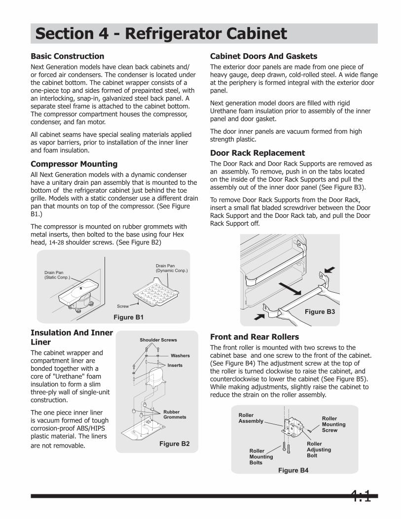
Compressor MountingAll Next Generation models with a dynamic condenser have a unitary drain pan assembly that is mounted to the bottom of the refrigerator cabinet just behind the toe grille. Models with a static condenser use a different drain pan that mounts on top of the compressor. (See Figure B1.)
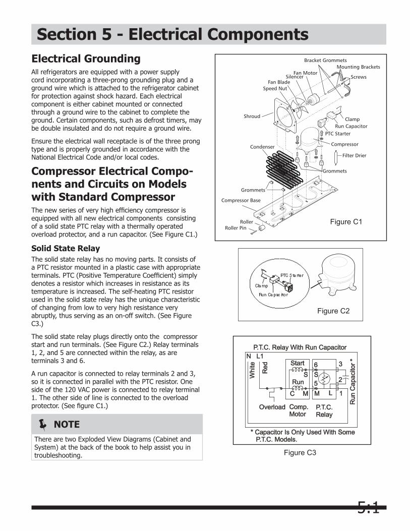
The compressor is mounted on rubber grommets with metal inserts, then bolted to the base using four Hex head, 14-28 shoulder screws. (See Figure B2)
Figure B1
Insulation And Inner LinerThe cabinet wrapper and compartment liner are bonded together with a core of "Urethane" foam insulation to form a slim three-ply wall of single-unit construction.
The one piece inner liner is vacuum formed of tough corrosion-proof ABS/HIPS plastic material. The liners are not removable. Figure B2
Front and Rear Rollers The front roller is mounted with two screws to the cabinet base and one screw to the front of the cabinet. (See Figure B4) The adjustment screw at the top of the roller is turned clockwise to raise the cabinet, and counterclockwise to lower the cabinet (See Figure B5). While making adjustments, slightly raise the cabinet to reduce the strain on the roller assembly.
Figure B4
Figure B3
Cabinet Doors And GasketsThe exterior door panels are made from one piece of heavy gauge, deep drawn, cold-rolled steel. A wide flange at the periphery is formed integral with the exterior door panel.
Next generation model doors are filled with rigid Urethane foam insulation prior to assembly of the inner panel and door gasket.
The door inner panels are vacuum formed from high strength plastic.
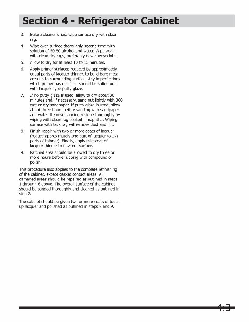
Door Rack ReplacementThe Door Rack and Door Rack Supports are removed as an assembly. To remove, push in on the tabs located on the inside of the Door Rack Supports and pull the assembly out of the inner door panel (See Figure B3).
To remove Door Rack Supports from the Door Rack, insert a small flat bladed screwdriver between the Door Rack Support and the Door Rack tab, and pull the Door Rack Support off.

4:2
3. Squeeze flared end of roller pin together using pair of pliers.
4. Pull roller pin free of roller and compressor base. Roller should fall free. If not, you may have to tap roller lightly with hammer to free it from compressor base.
5. Reassemble in reverse order.
Figure B5
Control HousingThe control housing is mounted to the top of the refrigreator compartment with four ¼" screws. The housing contains a Temperature Control Thermostat, Defrost Timer, Light Switch and a Temperature Control Knob. (See Figure B7)
Cabinet Touch-Up ProcedureVinyl gaskets are used on all models. Lacquer repairs can be made on all areas of the cabinet except any painted surface that comes in contact with the vinyl gasket. Since prolonged contact of vinyl gaskets with lacquer will soften the lacquer, repairs in these areas should not be attempted.
LacquerRefinishing
The following steps to touch-up or refinish a acrylic painted cabinet, except in gasket contact areas.
1. Sand out spot to be repaired with 360 or 400 wet-or-dry sandpaper. Finish sanding to feather edge with 600 wet-or-dry sandpaper. Wipe area dry. Hand rub with fine rubbing compound (Dupont VZ1090® or equivalent), the area extending at least six inches beyond edges of lacquer repair spot. Wipe com pound off and wash area with Naphtha. Dry with clean cloth.
2. Prepare bare metal with Sol-Kleen® cleaner and rust remover. Reduce cleaner with two parts water, and apply with a clean wet rag. Do not touch painted surface with this cleaner. Stubborn or deep seated rust can be removed by applying cleaner with steel wool.
Figure B7
To Remove Front Roller Assembly:
1. Disconnect refrigerator from electrical power.
2. Raise and support cabinet.
3. Remove two bolts securing roller to bottom of refrigerator.
4. Remove one screw securing roller to front of cabinet. Roller should fall free.
5. Reassemble in reverse order.
To Remove Rear Roller: (See Figure B6)
Section 4 - Refrigerator Cabinet
NOTEThe rear roller assembly is mounted to the bottom of the compressor base. Raise and support cabinet before removing rear roller.
1. Disconnect refrigerator from electrical power.
2. Raise and support cabinet.
NOTEThe end of the roller pin that protrudes through the roller has been flared to prevent it from slipping out. You will have to squeeze it back together with a pair of pliers before it will slide out for removal.
Figure B6
NOTEPrepare surface of bare metal with Sol-Kleen®
regardless if rust is present.
4:3
3. Before cleaner dries, wipe surface dry with clean rag.
4. Wipe over surface thoroughly second time with solution of 50-50 alcohol and water. Wipe again with clean dry rags, preferably new cheesecloth.
5. Allow to dry for at least 10 to 15 minutes.
6. Apply primer surfacer, reduced by approximately equal parts of lacquer thinner, to build bare metal area up to surrounding surface. Any imperfections which primer has not filled should be knifed out with lacquer type putty glaze.
7. If no putty glaze is used, allow to dry about 30 minutes and, if necessary, sand out lightly with 360 wet-or-dry sandpaper. If putty glaze is used, allow about three hours before sanding with sandpaper and water. Remove sanding residue thoroughly by wiping with clean rag soaked in naphtha. Wiping surface with tack rag will remove dust and lint.
8. Finish repair with two or more coats of lacquer (reduce approximately one part of lacquer to 1½ parts of thinner). Finally, apply mist coat of lacquer thinner to flow out surface.
9. Patched area should be allowed to dry three or more hours before rubbing with compound or polish.
This procedure also applies to the complete refinishing of the cabinet, except gasket contact areas. All damaged areas should be repaired as outlined in steps 1 through 6 above. The overall surface of the cabinet should be sanded thoroughly and cleaned as outlined in step 7.
The cabinet should be given two or more coats of touch-up lacquer and polished as outlined in steps 8 and 9.
Section 4 - Refrigerator Cabinet
5:1
Section 5 - Electrical ComponentsElectrical GroundingAll refrigerators are equipped with a power supply cord incorporating a three-prong grounding plug and a ground wire which is attached to the refrigerator cabinet for protection against shock hazard. Each electrical component is either cabinet mounted or connected through a ground wire to the cabinet to complete the ground. Certain components, such as defrost timers, may be double insulated and do not require a ground wire.
Ensure the electrical wall receptacle is of the three prong type and is properly grounded in accordance with the National Electrical Code and/or local codes.
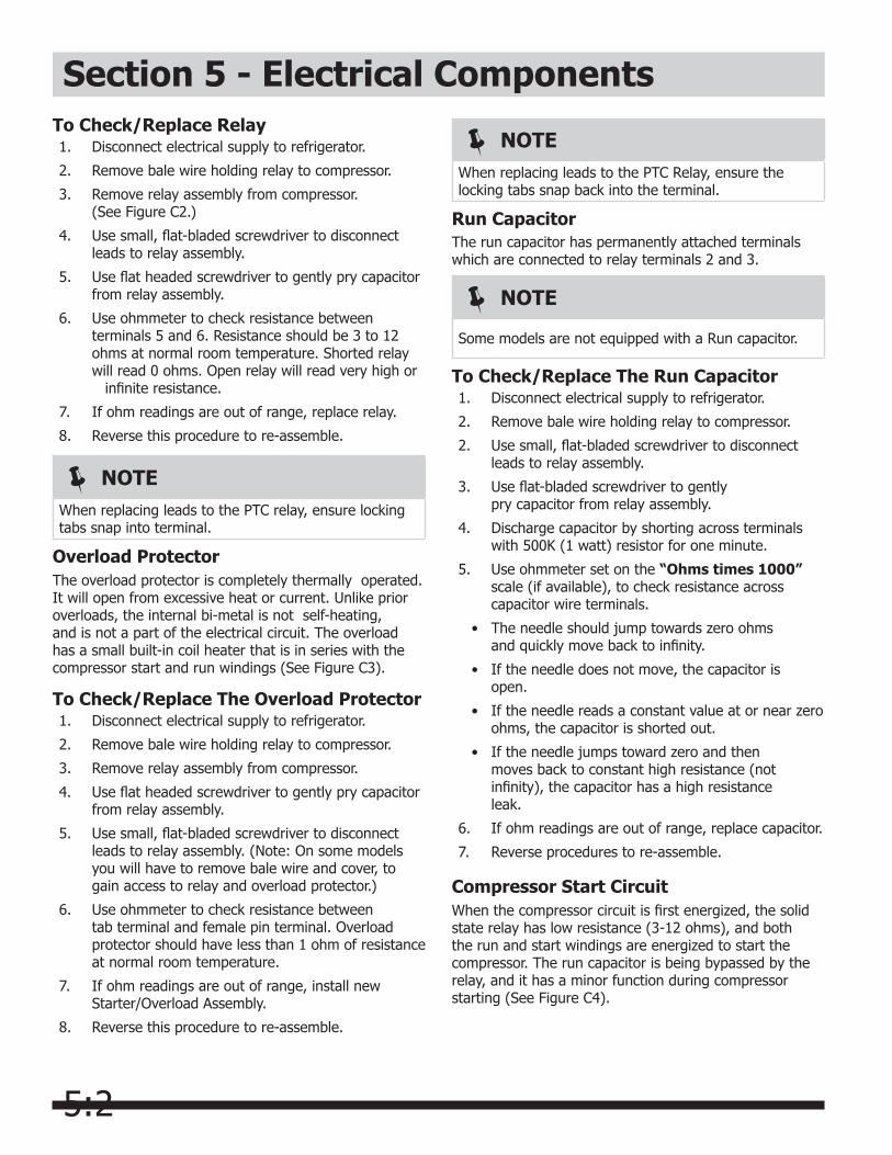
Compressor Electrical Compo-nents and Circuits on Models with Standard CompressorThe new series of very high efficiency compressor is equipped with all new electrical components consisting of a solid state PTC relay with a thermally operated overload protector, and a run capacitor. (See Figure C1.)
Solid State RelayThe solid state relay has no moving parts. It consists of a PTC resistor mounted in a plastic case with appropriate terminals. PTC (Positive Temperature Coefficient) simply denotes a resistor which increases in resistance as its temperature is increased. The self-heating PTC resistor used in the solid state relay has the unique characteristic of changing from low to very high resistance very abruptly, thus serving as an on-off switch. (See Figure C3.)
The solid state relay plugs directly onto the compressor start and run terminals. (See Figure C2.) Relay terminals 1, 2, and 5 are connected within the relay, as are terminals 3 and 6.
A run capacitor is connected to relay terminals 2 and 3, so it is connected in parallel with the PTC resistor. One side of the 120 VAC power is connected to relay terminal 1. The other side of line is connected to the overload protector. (See figure C1.)
Figure C2
NOTEThere are two Exploded View Diagrams (Cabinet and System) at the back of the book to help assist you in troubleshooting.
Figure C1
Figure C3
5:2
To Check/Replace The Overload Protector1. Disconnect electrical supply to refrigerator.
2. Remove bale wire holding relay to compressor.
3. Remove relay assembly from compressor.
4. Use flat headed screwdriver to gently pry capacitor from relay assembly.
5. Use small, flat-bladed screwdriver to disconnect leads to relay assembly. (Note: On some models you will have to remove bale wire and cover, to gain access to relay and overload protector.)
6. Use ohmmeter to check resistance between tab terminal and female pin terminal. Overload protector should have less than 1 ohm of resistance at normal room temperature.
7. If ohm readings are out of range, install new Starter/Overload Assembly.
8. Reverse this procedure to re-assemble.
Run CapacitorThe run capacitor has permanently attached terminals which are connected to relay terminals 2 and 3.
To Check/Replace The Run Capacitor1. Disconnect electrical supply to refrigerator.
2. Remove bale wire holding relay to compressor.
2. Use small, flat-bladed screwdriver to disconnect leads to relay assembly.
3. Use flat-bladed screwdriver to gently pry capacitor from relay assembly.
4. Discharge capacitor by shorting across terminals with 500K (1 watt) resistor for one minute.
5. Use ohmmeter set on the “Ohms times 1000” scale (if available), to check resistance across capacitor wire terminals.
• The needle should jump towards zero ohms and quickly move back to infinity.
• If the needle does not move, the capacitor is open.
• If the needle reads a constant value at or near zero ohms, the capacitor is shorted out.
• If the needle jumps toward zero and then moves back to constant high resistance (not infinity), the capacitor has a high resistance leak.
6. If ohm readings are out of range, replace capacitor.
7. Reverse procedures to re-assemble.
Compressor Start CircuitWhen the compressor circuit is first energized, the solid state relay has low resistance (3-12 ohms), and both the run and start windings are energized to start the compressor. The run capacitor is being bypassed by the relay, and it has a minor function during compressor starting (See Figure C4).
NOTEWhen replacing leads to the PTC Relay, ensure the locking tabs snap back into the terminal.
NOTE
Some models are not equipped with a Run capacitor.
To Check/Replace Relay1. Disconnect electrical supply to refrigerator.
2. Remove bale wire holding relay to compressor.
3. Remove relay assembly from compressor. (See Figure C2.)
4. Use small, flat-bladed screwdriver to disconnect leads to relay assembly.
5. Use flat headed screwdriver to gently pry capacitor from relay assembly.
6. Use ohmmeter to check resistance between terminals 5 and 6. Resistance should be 3 to 12 ohms at normal room temperature. Shorted relay will read 0 ohms. Open relay will read very high or infinite resistance.
7. If ohm readings are out of range, replace relay.
8. Reverse this procedure to re-assemble.
Overload ProtectorThe overload protector is completely thermally operated. It will open from excessive heat or current. Unlike prior overloads, the internal bi-metal is not self-heating, and is not a part of the electrical circuit. The overload has a small built-in coil heater that is in series with the compressor start and run windings (See Figure C3).
NOTEWhen replacing leads to the PTC relay, ensure locking tabs snap into terminal.
Section 5 - Electrical Components
5:3
Figure C4
Section 5 - Electrical Components
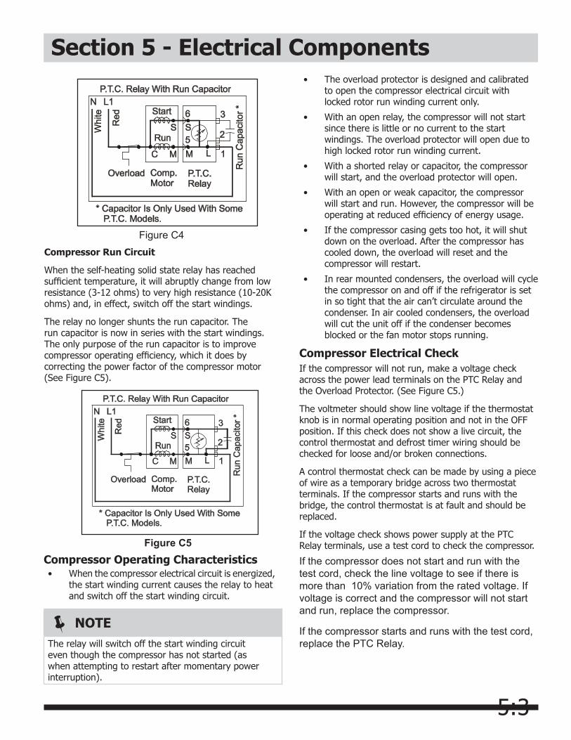
Compressor Run Circuit
When the self-heating solid state relay has reached sufficient temperature, it will abruptly change from low resistance (3-12 ohms) to very high resistance (10-20K ohms) and, in effect, switch off the start windings.
The relay no longer shunts the run capacitor. The run capacitor is now in series with the start windings. The only purpose of the run capacitor is to improve compressor operating efficiency, which it does by correcting the power factor of the compressor motor (See Figure C5).
Figure C5Compressor Operating Characteristics• When the compressor electrical circuit is energized,
the start winding current causes the relay to heat and switch off the start winding circuit.
NOTEThe relay will switch off the start winding circuit even though the compressor has not started (as when attempting to restart after momentary power interruption).
• The overload protector is designed and calibrated to open the compressor electrical circuit with locked rotor run winding current only.
• With an open relay, the compressor will not start since there is little or no current to the start windings. The overload protector will open due to high locked rotor run winding current.
• With a shorted relay or capacitor, the compressor will start, and the overload protector will open.
• With an open or weak capacitor, the compressor will start and run. However, the compressor will be operating at reduced efficiency of energy usage.
• If the compressor casing gets too hot, it will shut down on the overload. After the compressor has cooled down, the overload will reset and the compressor will restart.
• In rear mounted condensers, the overload will cycle the compressor on and off if the refrigerator is set in so tight that the air can’t circulate around the condenser. In air cooled condensers, the overload will cut the unit off if the condenser becomes blocked or the fan motor stops running.
Compressor Electrical CheckIf the compressor will not run, make a voltage check across the power lead terminals on the PTC Relay and the Overload Protector. (See Figure C5.)
The voltmeter should show line voltage if the thermostat knob is in normal operating position and not in the OFF position. If this check does not show a live circuit, the control thermostat and defrost timer wiring should be checked for loose and/or broken connections.
A control thermostat check can be made by using a piece of wire as a temporary bridge across two thermostat terminals. If the compressor starts and runs with the bridge, the control thermostat is at fault and should be replaced.
If the voltage check shows power supply at the PTC Relay terminals, use a test cord to check the compressor.
If the compressor does not start and run with the test cord, check the line voltage to see if there is more than 10% variation from the rated voltage. If voltage is correct and the compressor will not start and run, replace the compressor.
If the compressor starts and runs with the test cord, replace the PTC Relay.
5:4
Section 5 - Electrical ComponentsControl ThermostatAutomatic Defrost Models
The control thermostat is a variable cut-in type. When the thermostat knob is changed from one setting to another, both cut-in and cut-out temperature change. The degrees of temperature change are determined by the knob setting.
To Remove Temperature Control
1. Disconnect electrical supply to refrigerator.
2. Remove four screws securing housing to top of refrigerator compartment.
3. Unplug molex connector.
4. Remove Temperature Control knob.
5. To remove Temperature Control from housing, pull back on two tabs and lift Temperature Control out. (See figure C7.)
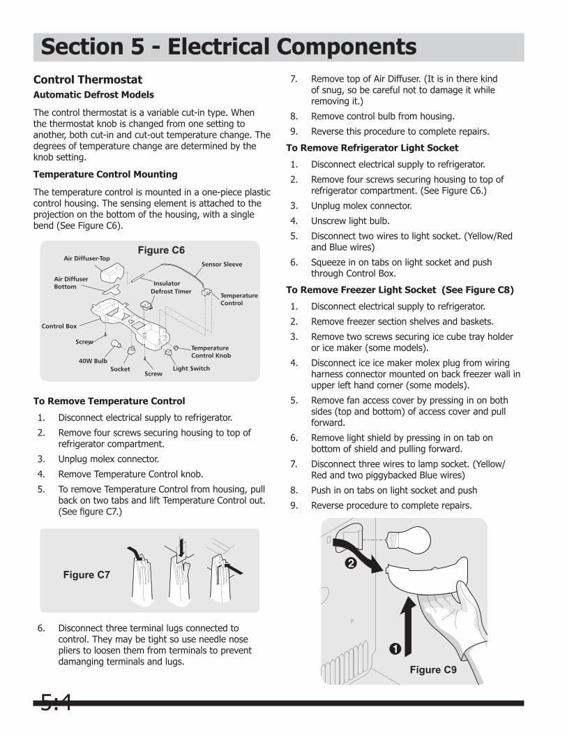
Temperature Control Mounting
The temperature control is mounted in a one-piece plastic control housing. The sensing element is attached to the projection on the bottom of the housing, with a single bend (See Figure C6).
Figure C7
Figure C6
6. Disconnect three terminal lugs connected to control. They may be tight so use needle nose pliers to loosen them from terminals to prevent damanging terminals and lugs.
7. Remove top of Air Diffuser. (It is in there kind of snug, so be careful not to damage it while removing it.)
8. Remove control bulb from housing.
9. Reverse this procedure to complete repairs.
To Remove Refrigerator Light Socket
1. Disconnect electrical supply to refrigerator.
2. Remove four screws securing housing to top of refrigerator compartment. (See Figure C6.)
3. Unplug molex connector.
4. Unscrew light bulb.
5. Disconnect two wires to light socket. (Yellow/Red and Blue wires)
6. Squeeze in on tabs on light socket and push through Control Box.
To Remove Freezer Light Socket (See Figure C8)
1. Disconnect electrical supply to refrigerator.
2. Remove freezer section shelves and baskets.
3. Remove two screws securing ice cube tray holder or ice maker (some models).
4. Disconnect ice ice maker molex plug from wiring harness connector mounted on back freezer wall in upper left hand corner (some models).
5. Remove fan access cover by pressing in on both sides (top and bottom) of access cover and pull forward.
6. Remove light shield by pressing in on tab on bottom of shield and pulling forward.
7. Disconnect three wires to lamp socket. (Yellow/ Red and two piggybacked Blue wires)
8. Push in on tabs on light socket and push
9. Reverse procedure to complete repairs.
Figure C9
5:5
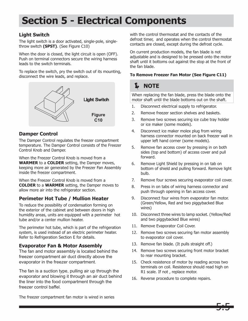
Section 5 - Electrical ComponentsLight SwitchThe light switch is a door activated, single-pole, single-throw switch (SPST). (See Figure C10)
When the door is closed, the light circuit is open (OFF). Push on terminal connectors secure the wiring harness leads to the switch terminals.
To replace the switch, pry the switch out of its mounting, disconnect the wire leads, and replace.
Damper ControlThe Damper Control regulates the freezer compartment temperature. The Damper Control consists of the Freezer Control Knob and Damper.
When the Freezer Control Knob is moved from a WARMER to a COLDER setting, the Damper moves, keeping more air generated by the Freezer Fan Assembly inside the freezer compartment.
When the Freezer Control Knob is moved from a COLDER to a WARMER setting, the Damper moves to allow more air into the refrigerator section.
Perimeter Hot Tube / Mullion HeaterTo reduce the possibility of condensation forming on the exterior of the cabinet and between doors in high humidity areas, units are equipped with a perimeter hot tube and/or a center mullion heater.
The perimeter hot tube, which is part of the refrigeration system, is used instead of an electric perimeter heater. Refer to Refrigeration Section E for details.
Evaporator Fan & Motor AssemblyThe fan and motor assembly is located behind the freezer compartment air duct directly above the evaporator in the freezer compartment.
The fan is a suction type, pulling air up through the evaporator and blowing it through an air duct behind the liner into the food compartment through the freezer control baffel.
The freezer compartment fan motor is wired in series
Figure C10
with the control thermostat and the contacts of the defrost timer, and operates when the control thermostat contacts are closed, except during the defrost cycle.
On current production models, the fan blade is not adjustable and is designed to be pressed onto the motor shaft until it bottoms out against the stop at the front of the fan blade.
To Remove Freezer Fan Motor (See Figure C11)
NOTEWhen replacing the fan blade, press the blade onto the motor shaft until the blade bottoms out on the shaft.
1. Disconnect electrical supply to refrigerator.
2. Remove freezer section shelves and baskets.
3. Remove two screws securing ice cube tray holder or ice maker (some models).
4. Disconnect ice maker molex plug from wiring harness connector mounted on back freezer wall in upper left hand corner (some models).
5. Remove fan access cover by pressing in on both sides (top and bottom) of access cover and pull forward.
6. Remove Light Shield by pressing in on tab on bottom of shield and pulling forward. Remove light bulb.
7. Remove four screws securing evaporator coil cover.
8. Press in on tabs of wiring harness connector and push through opening in fan access cover.
9. Disconnect four wires from evaporator fan motor. (Green/Yellow, Red and two piggybacked Blue wires)
10. Disconnect three wires to lamp socket. (Yellow/Red and two piggybacked Blue wires)
11. Remove Evaporator Coil Cover.
12. Remove two screws securing fan motor assembly to evaporator coil cover.
13. Remove fan blade. (It pulls straight off.)
14. Remove two screws securing front motor bracket to rear mounting bracket.
15. Check resistence of motor by reading across two terminals on coil. Resistence should read high on R1 scale. If not , replace motor.
16. Reverse procedure to complete repairs.
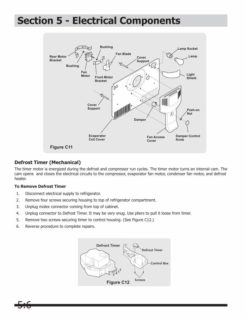
5:6
Section 5 - Electrical Components
Figure C11
Defrost Timer (Mechanical)The timer motor is energized during the defrost and compressor run cycles. The timer motor turns an internal cam. The cam opens and closes the electrical circuits to the compressor, evaporator fan motor, condenser fan motor, and defrost heater.
To Remove Defrost Timer
1. Disconnect electrical supply to refrigerator.
2. Remove four screws securing housing to top of refrigerator compartment.
3. Unplug molex connector coming from top of cabinet.
4. Unplug connector to Defrost Timer. It may be very snug. Use pliers to pull it loose from timer.
5. Remove two screws securing timer to control housing. (See Figure C12.)
6. Reverse procedure to complete repairs.
Figure C12
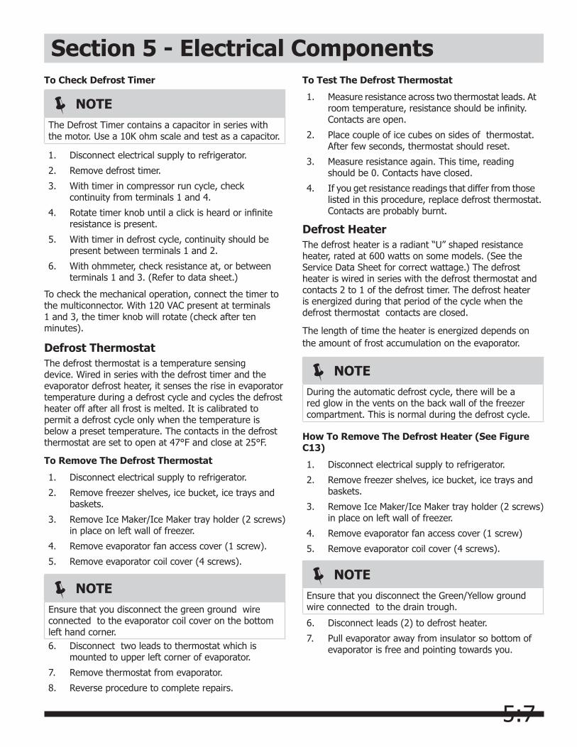
5:7
Section 5 - Electrical ComponentsTo Check Defrost Timer
NOTEThe Defrost Timer contains a capacitor in series with the motor. Use a 10K ohm scale and test as a capacitor.
1. Disconnect electrical supply to refrigerator.
2. Remove defrost timer.
3. With timer in compressor run cycle, check continuity from terminals 1 and 4.
4. Rotate timer knob until a click is heard or infinite resistance is present.
5. With timer in defrost cycle, continuity should be present between terminals 1 and 2.
6. With ohmmeter, check resistance at, or between terminals 1 and 3. (Refer to data sheet.)
To check the mechanical operation, connect the timer to the multiconnector. With 120 VAC present at terminals 1 and 3, the timer knob will rotate (check after ten minutes).
Defrost ThermostatThe defrost thermostat is a temperature sensing device. Wired in series with the defrost timer and the evaporator defrost heater, it senses the rise in evaporator temperature during a defrost cycle and cycles the defrost heater off after all frost is melted. It is calibrated to permit a defrost cycle only when the temperature is below a preset temperature. The contacts in the defrost thermostat are set to open at 47°F and close at 25°F.
To Remove The Defrost Thermostat
1. Disconnect electrical supply to refrigerator.
2. Remove freezer shelves, ice bucket, ice trays and baskets.
3. Remove Ice Maker/Ice Maker tray holder (2 screws) in place on left wall of freezer.
4. Remove evaporator fan access cover (1 screw).
5. Remove evaporator coil cover (4 screws).
6. Disconnect two leads to thermostat which is mounted to upper left corner of evaporator.
7. Remove thermostat from evaporator.
8. Reverse procedure to complete repairs.
NOTEEnsure that you disconnect the green ground wire connected to the evaporator coil cover on the bottom left hand corner.
To Test The Defrost Thermostat
1. Measure resistance across two thermostat leads. At room temperature, resistance should be infinity. Contacts are open.
2. Place couple of ice cubes on sides of thermostat. After few seconds, thermostat should reset.
3. Measure resistance again. This time, reading should be 0. Contacts have closed.
4. If you get resistance readings that differ from those listed in this procedure, replace defrost thermostat. Contacts are probably burnt.
Defrost HeaterThe defrost heater is a radiant “U” shaped resistance heater, rated at 600 watts on some models. (See the Service Data Sheet for correct wattage.) The defrost heater is wired in series with the defrost thermostat and contacts 2 to 1 of the defrost timer. The defrost heater is energized during that period of the cycle when the defrost thermostat contacts are closed.
The length of time the heater is energized depends on the amount of frost accumulation on the evaporator.
NOTEDuring the automatic defrost cycle, there will be a red glow in the vents on the back wall of the freezer compartment. This is normal during the defrost cycle.
How To Remove The Defrost Heater (See Figure C13)
1. Disconnect electrical supply to refrigerator.
2. Remove freezer shelves, ice bucket, ice trays and baskets.
3. Remove Ice Maker/Ice Maker tray holder (2 screws) in place on left wall of freezer.
4. Remove evaporator fan access cover (1 screw)
5. Remove evaporator coil cover (4 screws).
NOTEEnsure that you disconnect the Green/Yellow ground wire connected to the drain trough.
6. Disconnect leads (2) to defrost heater.
7. Pull evaporator away from insulator so bottom of evaporator is free and pointing towards you.
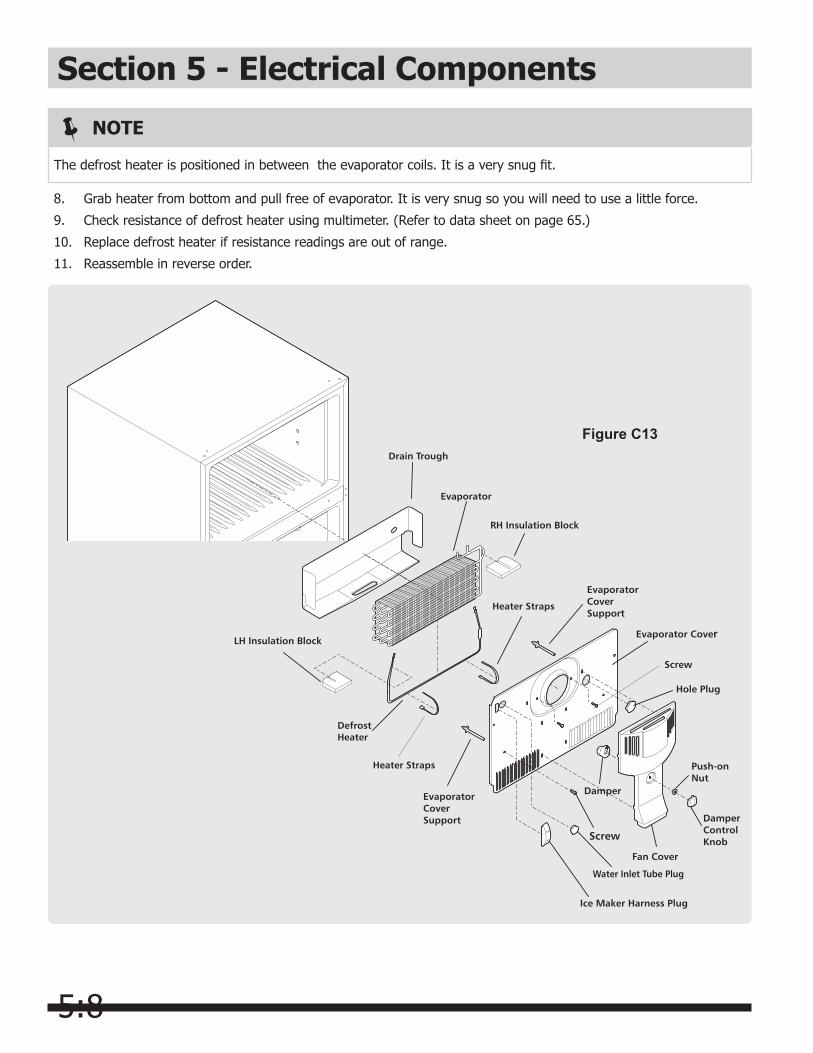
5:8
8. Grab heater from bottom and pull free of evaporator. It is very snug so you will need to use a little force.
9. Check resistance of defrost heater using multimeter. (Refer to data sheet on page 65.)
10. Replace defrost heater if resistance readings are out of range.
11. Reassemble in reverse order.
Section 5 - Electrical Components
NOTE
The defrost heater is positioned in between the evaporator coils. It is a very snug fit.
Figure C13

5:9
Section 5 - Electrical ComponentsAdaptive Defrost Control (Adc)Electrical Requirements
Input Voltage:
• Voltage between L1 (BLK) and Neutral (LT BLU) connector on the PC Board shall be 115 VAC ± 10%, 60 Hertz.
• Cold Control (ORG) supplies line voltage to the ADC relay center contact.
• Defrost termination (BLU-B) sensing is between the defrost heater and the bimetal thermostat. The heater is on the hot side of the line and the bimetal thermostat on the neutral.
• Door Switch (YEL/BLK) sensing is between the door switch and the light bulb. (YEL/BLK)on the PC Board)
Output Voltage:
• Output voltage to the defrost heater (BRN) and compressor (RED) is equal to the input voltage from the cold control (ORG).
The PC Board will withstand the following electrical loads for temperatures as high as 110°F.
The ADC will dissipate an average of no more than 0.4 watts. The normal operating life is 22,000 defrost cycles over a 15 year period.
Defrost Time Change in Defrost Interval
Defrost Interval
</=(T range, min) + 2 hours Max 12 hours
>=(T range, min)</=(T range, max)
No change Defrost Heater
>=(T range, max) - 2 hours Min 6 hours
Initial Start & Power Interruptions
When power is applied to the power cord:
• If the defrost termination thermostat is closed, a cycle will be initiated after 1 hour.
• If the defrost termination thermostat is open, a compressor cycle starts immediately.
ADC Characteristics
The ADC has a base defrost interval of 6 hours of run time. All defrost interval timing starts with the compressor pull-down after a defrost or initial cabinet power.
When time for a defrost:
• If the compressor has been running equal to or more than 1 hour, defrost immediately.
• If the compressor continues to run less than 1 hour, initiate the defrost immediately after that 1 hour.
• If compressor continues to run for 1 hour after time for defrost, initiate the defrost immediately after that 1 hour.
The adapative defrost logic operates as follows:
The maximum defrost cycle must be terminated after 24 minutes. After each defrost heater termination, there must be a 6 minute delay before the compressor starts, but there is no time delay when the defrost heater has been on for 24 minutes.
Vacation Mode
When the defrost interval has reached 12 hours and the door has not been opened in the last 24 hours, the ADC places the refrigeration unit in vacation mode. Once in vacation mode, the defrost heater will be turned on after 72 hours. If the door has not been opened and the heater ON time is less than 16 minutes, then the defrost heater is turned on after 72 hours. Should the door not be opened but the heater runs for longer than 16 minutes, then the algorithm restarts in 6 hours.Once the refrigeration unit has been placed in vacation mode, if the door is opened and the compressor run time since the last defrost has been at least 5 hours, a defrost is initiated after 1 hour compressor run time since the initial door opening.
Amps Duration of Load Reason for Load
15 3 seconds Locked Rotor
5 30 minutes Defrost Heater
3 Indefinite Compressor Running

5:10
Section 5 - Electrical Components
The maximum defrost cycle must be terminated after 24 minutes. After each defrost heater termination, there must be a 6 minute delay before compressor start except no time delay when the defrost heater has been on for 24 minutes.
System Diagnostics
An electrical connection between the light switch and refrigerator light bulb is coupled to the ADC system board, providing a manual method of initiating defrost and back to compressor. The actuation code will be a mininum of five depressions of the light switch within a six second time period.
• If a defrost is initiated manually and the termination thermostat is closed, the heater will be actuated until the termination thermostat opens. A six minute drip time follows before actuating the compressor and setting x= (xnitial).
• If a defrost is initiated manally and the termination thermostat is open, a six minute drip time is initiated before actuating the compresspor and setting x =(xinitial).
• When terminating the defrost manually and the termination thermostat is closed or open, the compressor is actuated and sets x = (xinitial).
An electrical connection between the defrost heater and defrost termination thermostat is coupled to the ADC for system data, but also gives the technician the ability to check electrical continuity individually of either the defrost heater or termination thermostat from the ADC mounting area.
The ADC printed circuit board has component identification and lead wire color (name) on the cover of the housing containing the ADC board.
To Remove Adaptive Defrost Control (ADC)
1. Disconnect electrical supply to refrigerator.
2. Remove four screws securing housing to top of refrigerator compartment.
3. Unplug molex connector coming from top of cabinet.
Figure C14
Defrost Parameter Values
X initial 6 hours (min. defrost interval)
X max 12 hours (max defrost interval)
X max, v 72 hours (max defrost interval during vacation mode)
T range, min 12 minutes (min. heater on time for an “ideal” frost)
T range, max 16 minutes (max. heater on time for an “ideal” frost)
4. Unplug connector to the ADC by pushing in on the lock tab and pulling stright out on the connector.
5. Remove two screws securing ADC to control housing. (See Figure C14.)
6. Reverse procedure to complete repairs.
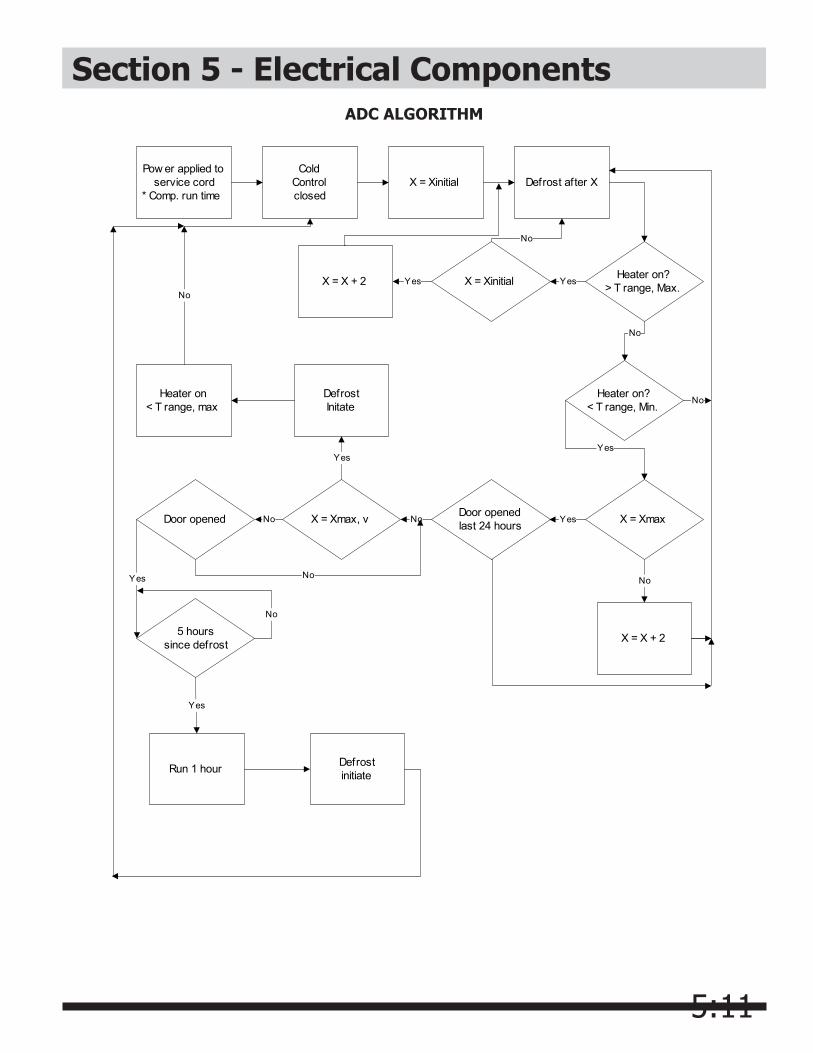
5:11
Section 5 - Electrical ComponentsADC ALGORITHM
Pow er applied toservice cord
* Comp. run time
ColdControlclosed
X = Xinitial Defrost after X
Heater on?> T range, Max.
Heater on?< T range, Min.
X = Xmax
X = X + 2
No
Door openedlast 24 hours Yes
X = Xinitial Yes
No
X = X + 2 Yes
X = Xmax, v No
DefrostInitate
Yes
Heater on< T range, max No
No
Yes
Door opened No
No
5 hourssince defrost
Yes
No
Run 1 hour
Yes
Defrostinitiate
No
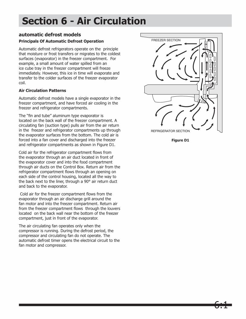
6:1
automatic defrost modelsPrincipals Of Automatic Defrost Operation
Automatic defrost refrigerators operate on the principle that moisture or frost transfers or migrates to the coldest surfaces (evaporator) in the freezer compartment. For example, a small amount of water spilled from an ice cube tray in the freezer compartment will freeze immediately. However, this ice in time will evaporate and transfer to the colder surfaces of the freezer evaporator coil.
Air Circulation Patterns
Automatic defrost models have a single evaporator in the freezer compartment, and have forced air cooling in the freezer and refrigerator compartments.
The “fin and tube” aluminum type evaporator is located on the back wall of the freezer compartment. A circulating fan (suction type) pulls air from the air return in the freezer and refrigerator compartments up through the evaporator surfaces from the bottom. The cold air is forced into a fan cover and discharged into the freezer and refrigerator compartments as shown in Figure D1.
Cold air for the refrigerator compartment flows from the evaporator through an air duct located in front of the evaporator cover and into the food compartment through air ducts on the Control Box. Return air from the refrigerator compartment flows through an opening on each side of the control housing, located all the way to the back next to the liner, through a 90° air return duct and back to the evaporator.
Cold air for the freezer compartment flows from the evaporator through an air discharge grill around the fan motor and into the freezer compartment. Return air from the freezer compartment flows through the louvers located on the back wall near the bottom of the freezer compartment, just in front of the evaporator.
The air circulating fan operates only when the compressor is running. During the defrost period, the compressor and circulating fan do not operate. The automatic defrost timer opens the electrical circuit to the fan motor and compressor.
Figure D1
Section 6 - Air Circulation

7:1
Section 7 - Refrigeration System
DefinitionsRecovery:To remove refrigerant in any condition from a system and store it in an external container without necessarily testing or processing it in any way.
Recycling:To clean refrigerant for reuse by oil separation and single or multiple passes through devices, such as replaceable core filter-driers, which reduce moisture, acidity and particulate matter. This term usually applies to procedures implemented at the field job site or at a local service shop.
Reclaim:To reprocess refrigerant to new product specifications by means which may include distillation. Will require chemical analysis of the refrigerant to determine that appropriate product specifications are met. This term usually implies the use of processes or procedures available only at a reprocessing or manufacturing facility.
Safety WarningsCompressor TestingWhenever testing a compressor, extreme caution should be used to prevent damaging the terminals. A compressor with a damaged terminal or a grounded winding can expel a terminal from its insulated housing when the compressor is energized. If this happens, a mixture of refrigerant and oil will be released that could be ignited by an external heat source (open flame, heater, etc.). Also, if there is air in the system when this happens, a spark at the compressor shell could ignite the refrigerant and oil mixture.
Charging Sealed SystemsOvercharging a refrigeration system with refrigerant can be dangerous. If the overcharge is sufficient to immerse the major parts of the motor and compressor in liquid refrigerant, a situation has been created which, when followed by a sequence of circumstances can lead to the compressor shell seam separating.
A hydraulic block occurs, preventing the compressor from starting. This condition is known as locked rotor. Electric current continues to flow through the compressor motor windings which become, in effect, electric resistance heaters. The heat produced begins to vaporize the excess refrigerant liquid causing a rapid increase in system pressure. If the compressor protective devices fail, the pressure within the system may rise to extremes far in excess of the design limits. Under these conditions, the weld seam around the compressor shell can separate with explosive force, spewing oil and refrigerant vapor which could ignite.
To eliminate this exceedingly rare but potential hazard, never add refrigerant to a sealed system. If refrigerant is required, evacuate the existing charge and recharge with the correct measured amount of the refrigerant specified for the system.
NOTICEInstructions given here are furnished as a guide. Persons attempting to use these instructions to make repairs to the sealed refrigeration system should have a working knowledge of refrigeration and previous training on sealed system repair, and an EPA certification for servicing refrigeration systems.
IMPORTANT NOTICEEffective July 1, 1992, the United States clean air act governs the disposal of refrigerants such as R-134a. Therefore, when discharging or purging the sealed system use an epa approved refrigerant recovery system as outlined in the final rule on the protection of stratospheric ozone and refrigerant recycling, which was published in the Federal Register May 14, 1993.
NOTEFrigidaire does not permit the use of recovered refrigerant in the servicing of our products for in-warranty and out-of-warranty repairs or for products covered by service contracts. Therefore, only new refrigerant or refrigerant that has been reclaimed back to new specifications by a refrigerant manufacturer is to be used.

7:2
Section 7 - Refrigeration SystemSoldering
1. All joints to be soldered must have proper fit. Clearance between tubes to be soldered should be from .001” to .006”. It is not practical to actually measure this; however, you do not want a dry fit or loose fit. Tubing joints should overlap about the distance of their diameter except for restrictor tubes, which should be inserted 1.25”.
2. Clean all joint areas with fine steel wool or preferably an abrasive cloth, such as grit cloth No. 23 or Scotch-Brite.
3. Apply a thin film of liquid flux recommended for silver soldering to surfaces to be joined and to surfaces immediately adjacent to joint.
4. Align tubing so no stress is on joint. Do not move tubing while solder is solidifying or leaks will result.
5. Use a torch of adequate capacity so joint can be quickly heated with a minimum of heat travel to other points. Use a good grade of silver solder.
6. Solder connections. If tubing is properly cleaned and fluxed, solder will flow readily. Use only enough solder to make a good bond.
7. Allow joint to cool, then wash exterior with water to remove flux.
Basic ComponentsThe basic components of a refrigerator are a compressor, condenser, evaporator, heat exchanger (capillary tube and suction line), drier and perimeter hot tube.
Perimeter Hot TubeTo reduce the possibility of condensation forming on the exterior of the cabinet in high humidity areas, a
perimeter hot tube (refrigerant tube) has been installed in the unit. The perimeter tube extends up the left side, across the top of the freezer and down the center mullion and into the filter drier. When the compressor operates, warm refrigerant flows through the primary condenser, then into the primary hot tube, warming the cabinet front exterior.
The perimeter hot tube is not replaceable. In the unlikely event of a leak in the hot tube, a kit is available to bypass the hot tube in the sealed system. A electrical heater wire must be installed within the tubing. Refer to the appropriate parts list of the model being serviced for the correct kit part number.
Refrigerant CycleThe refrigerant cycle is a continuous cycle that occurs whenever the compressor is in operation. Liquid refrigerant is evaporated in the evaporator by the heat that enters the cabinet through the insulated walls and by the heat from product load and door openings. The refrigerant vapor is then drawn from the evaporator, through the suction line to the compressor. Compression raises the pressure and temperature of the vapor in the compressor and the vapor is then forced through the discharge valve into the discharge line and into the condenser. Air passing over the condenser surface removes heat from the high pressure vapor which then condenses to a liquid. The liquid refrigerant then flows from the condenser to the evaporator through the small diameter liquid line (capillary tube). Before it enters the evaporator, the liquid refrigerant is sub-cooled in the heat exchanger by the low temperature suction vapor in the suction line.
Low/High Side Leak or UnderchargeA loss of refrigerant can result in any of the following:
1. Excessive or continuous compressor operation.
2. Above normal freezer and /or food compartment temperature.
3. A partially frosted evaporator (depending on amount of refrigerant loss).
4. Below normal freezer compartment temperature.
5. Low suction pressure (vacuum).
6. Low wattage.
The condenser will be “warm to cool”, depending on the amount of refrigerant lost.
When refrigerant is added, the frost pattern will improve, the suction and discharge pressures will rise, the condenser will become hot and the wattage will increase.
WARNINGWear approved safety glasses when working with or on any pressurized system or equipment. haveanapproveddrytypefireextinguisherhandy when using any type of gas operated torch.
CAUTIONDuring application of heat, use wet cloths to prevent heat from conducting to areas other than the soldered joint. Use a sheet of metal ortorchguardpadasaheatdeflectortokeepflameawayfrominflammablematerialsandpainted surfaces.
7:3
Section 7 - Refrigeration SystemIn the case of a low side refrigerant leak resulting in complete loss of refrigerant, the compressor will run but will not refrigerate. Suction pressure will drop below atmospheric pressure and air and moisture will be drawn into the system saturating the filter drier.
If there is reason to believe the system has operated for a considerable length of time with no refrigerant and the leak occurred in the low side of the system, excessive amounts of moisture may have entered the system. In such cases the two stage service Dryer Filter part number 5303918288 and vacuum procedure listed under Refrigerant Leaks on page E 15 need to be followed to prevent repetitive service.
If a slight undercharge of refrigerant is indicated and no leak can be found after a thorough leak test, the charge can be corrected without changing the compressor.
If a high side leak is located and some refrigerant remains in the system it is not necessary to change the compressor.
Testing for Refrigerant LeaksIf the system is diagnosed as short of refrigerant and the system has not been recently opened, there is probably a leak in the system. Adding refrigerant without first locating and repairing the leak or replacing the component will not permanently correct the difficulty. The leak must be found. Sufficient refrigerant may have escaped to make it impossible to leak test effectively. In such cases, add a ¼” line piercing valve to the compressor process tube. Add sufficient refrigerant vapor to increase the pressure to 40 to 50 lb. per sq. in. Check the low side for leaks. Run the compressor 2 or 3 minutes and check the high side for leaks. Recover refrigerant using an EPA approved recovery system.
5. Leave pressure on hot tube for 24 hours. Any drop in pressure is indication of leak.
If dry nitrogen or carbon dioxide is not available, follow steps 1 through 3 above, then steps 4 and 5 below:
4. Connect gauges to charging hose fittings. Pull vacuum on hot tube.
5. Leave vacuum on each side of system for 24 hours. Any loss of vacuum indicates leak.
Checking for Internal (Hot Tube) LeaksBefore checking for internal leaks, check all accessible system components and joints for leaks.
If an internal hot tube leak is suspected, it must be confirmed. Use the following procedure:
1. Recover refrigerant by using EPA approved recovery system.
2. After system refrigerant is completely recovered,
disconnect drier from hot tube. Pinch off and solder end of hot tube closed.
3. Cut line from condenser to hot tube and solder a ¼”charging hose fitting to open end of hot tube or put compression fitting on tube.
4. Connect pressure gauge and access valve to hot tube and pressurize to 250 psig using dry nitrogen or carbon dioxide.
NOTEThe line piercing valve (clamp-on type) should be used for test purposes only. It must be removed from system after it has served its purpose.
WARNINGNever pressurize with oxygen. never open a high pressure tank unless it is equipped with a pressure regulator. never put high pressure on dome of compressor – it could explode. make suregauge,HOSES,ANDALLfittingsareingoodcondition and do not leak.
Compressor Replacement
To check for contamination, obtain oil sample from old compressor.
• If the oil has burned odor, but no color change or residue — follow instructions in section “Installing A New Compressor”.
• If oil has a burned odor and a sugar or gritty feel as well as showing signs of contamination (dark color) — follow instructions in next section, To Flush The System. Remove as much of contamination as possible from system before installing new compressor and filter-drier.
CAUTIONNEVERinstallanewcompressorwithoutfirstchecking for possible system contamination.

7:4
NOTEEntirely new compressors have been developed for use with R-134a and Ester oil refrigeration systems. Both compressor and electric motor have been modified. Old compressors intended for R-12 refrigerant must not be used for new systems charged with R-134a.
Section 7 - Refrigeration System
To Use Dry Nitrogen To Flush The System:
1. Remove compressor and filter-drier. Connect process coupling to outlet tube of condenser.
2. Fasten cloth over other end of coil to prevent old oil from spraying over room.
3. Connect hand shut-off valve on flushing hose to process coupling.
4. Slowly open hand shut-off valve and allow nitrogen to flow through condenser until discharge is clear.
7. Reassemble system.
To Use Refrigerant To Flush The System:
1. Disconnect the suction and discharge lines from the compressor and remove the filter-drier. Connect process coupling to outlet and inlet tube of condenser.
2. Connect hose to outlet process coupling and charging cylinder. Connect another hose to inlet coupling and recovery system.
3. Open charging cylinder and allow refrigerant to flow through condenser until discharge into bag is clear.
4. Disconnect capillary tube from evaporator. Flush evaporator in same manner as condenser.
5. Flush cap tube. This is only possible if you have proper service valve adaptor.
6. Reassemble system.
Installing a New Compressor
NOTEIt is recommended that system be flushed with dry Nitrogen. However, if refrigerant is used to flush the system you must look at the serial plate to see what type of refrigerant is used in the system. This is the only refrigerant that can be used to flush the system and it must be recovered.
CAUTIONUse extreme care when using Dry Nitrogen to flushsystems.Pressureinnitrogencylindercould be as high as 2000 psi. Nitrogen cylinder must be equipped with approved pressure regulator and pressure relief valve. Ensure that your hoses have adequate ratings for pressure involved and that all of your equipment is in good condition.Theendoftheflushinghoseonthistankregulator must be equipped with a hand shut-off valve (Robinair No. 40380). Close hand shut-off valve and adjust nitrogen regulator to correct pressurebeforeproceedingwithflushingprocedure.
CAUTION
DO NOT exceed 300 PSIG.
6. Flush cap tube. This is only possible if you have proper service valve adaptor.
CAUTION
DO NOT exceed 150 PSIG.
CAUTION
DO NOT exceed 300 PSIG.
CAUTIONRefrigerantusedforflushingmustberecoveredinto a recovery system. Meter amount of refrigerantusedforflushingwithyourchargingcylinder. DO NOT OVERFILL THESYSTEM.
NOTETo flush evaporator and heat exchanger you must remove evaporator from inside product to disconnect cap tube.
To Flush The System
5. Disconnect cap tube from evaporator. Flush evaporator in same manner as condenser.

7:5
Section 7 - Refrigeration SystemReplacement of compressor and installation of filter-drier must be done in a continuous sequence so system is exposed to atmosphere no longer than necessary.
All replacement compressors are shipped with rubber plugs in the suction, discharge and process tubes and contain the correct oil charge and a holding charge of inert gas. Compressors have a low-side process tube attached to the compressor shell. A high-side process tube is attached to the filter-drier.
Replacement compressors for refrigerator may have an oil cooler even if the original compressor did not. If the product is not equipped for an oil cooler, leave the plastic caps in place and install the compressor connecting only to the suction and discharge lines of the new compressor.
Before installing the replacement compressor remove the discharge plug and check for the pop sound of the inert gas leaving the compressor.
If the compressor checks OK, reinstall the plug. Do not remove any of the plugs again until the compressor is in position and you are ready to braze the lines.
A new compressor which is cold (e.g. after having been kept in a cold service van) should be left to warm to the surrounding temperature before the plugs on the compressor connections are removed. This will help prevent condensation from forming in the oil and the compressor. Also, avoid opening the system when any of the components or lines are cold.
1. Disconnect electrical supply to refrigerator.
2. Remove compressor access panel.
3. Remove rail and condenser fan shroud screws.
4. Unplug fan motor harness clamp located below heat exchanger wiring harness cover.
5. Disconnect condenser fan motor multiconnector.
6. Pull condenser assembly straight out (See Figure E-1).
7. Recover refrigerant by using EPA approved recovery system.
8. Remove leads from compressor motor terminals.
9. Remove mounting clips and washers.
WARNINGDo not operate reciprocating compressor when charging liquid refrigerant into system through its process tube.
CAUTIONDO NOT use compressor if you do not hear this sound.
CAUTIONOn R-134a systems, compressor must NOT be left open to atmosphere for more than 10 minutes to prevent moisture contamination of oil.
NOTERelease holding charge (release slowly to avoid oil discharge) on new compressor to ensure there is no leak in seam or tubing. Reinstall rubber plug.
10. After refrigerant is completely recovered, cut suction and discharge lines as close to compressor as possible. Leave only enough tubing to pinch off and seal defective compressor. Plug or tape any open system tubing to avoid entrance of moisture and air into system. Remove inoperable compressor and transfer mounting parts to new compressor.
11. Install new compressor in exact same manner as original compressor.
12. Reform both suction and discharge lines to align with new compressor. If they are too short, use additional lengths of tubing. Joints should overlap 0.5” to provide sufficient area for good solder joint. Clean and mark area where tubing should be cut. Cut tubing with tubing cutter. Work as quickly as possible to avoid letting moisture and air into system.
NOTEIf low-side process tube is too short, silver solder four inch piece of tubing onto process tube at this time.
13. Solder all connections according to soldering procedure.
14. Remove original filter-drier.
CAUTIONDONOTunbrazeoldfilter-drierfromsystem.This will vaporize and drive moisture from desiccantbackintosystem.Theoldfilter-driershould be cut out of system.
15. Install new filter-drier at condenser outlet.
16. Evacuate and charge system using recommended procedure described under Evacuating and Recharging.

7:6
Section 7 - Refrigeration System
Figure E1
17. Reconnect compressor terminal leads in accordance with refrigerator wiring diagram.
18. Reassemble unit.

7:7
Section 7 - Refrigeration SystemEvaporator Replacement
The evaporator is located in the upper section of the freezer and is secured to the drain pan by top and bottom brackets. Styrofoam blocks are located on each side, directly across from each other, to ensure proper air flow through the evaporator.
The heat exchanger on this style of refrigerator is in the insulation between the back of the food liner and the back of the cabinet. Because of this, you will not be able to remove the heat exchanger with the evaporator. You will make your line welds inside the freezer compartment. The kit contains a heat shield to protect the liner from damage when making your line welds.
Evaporator Kit Contents1 Evaporator
1 Drier-Filter
1 Heat Shield
1 Instruction Sheet
1. Disconnect electrical supply to refrigerator.
2. Remove all freezer section shelves and baskets.
3. Recover refrigerant using EPA approved recovery system.
4. Remove evaporator coil cover.
5. Cut suction line between weld and evaporator. Using file, score and break cap tube just above weld. (See Figure 1.)
6. Disconnect limiter and defrost heater.7. Clean end of suction line and cap tube. Straighten
and slightly bend toward front of cabinet.
8. Cut small “X” in heat shield and slide cap tube and suction line through hole. Pack heat shield in top corner of liner. (See Figure 2.) You may want to use small pair of vise-grips on suction line to help hold heat shield in place.
CAUTIONRemove any component part from the interior of the cabinet before attempting to solder. The excessive heat from soldering will warp the plastic liner.
9. Install defrost heater in new evaporator and set inside freezer. Do not push all the way in place. Sit evaporator 2 to 3 inches out from liner. This will allow additional room for welding. (See Figure 3.)
Cut small hole in middle of the shield.
Place shield over heat exchanger and push into top corner of liner.
Figure 2
To replace evaporator, cut suction line at this point.
Figure 1
Cut cap tube at this point.
Make your weld on cap tube first.
Now make your weld on suction line.
Figure 3
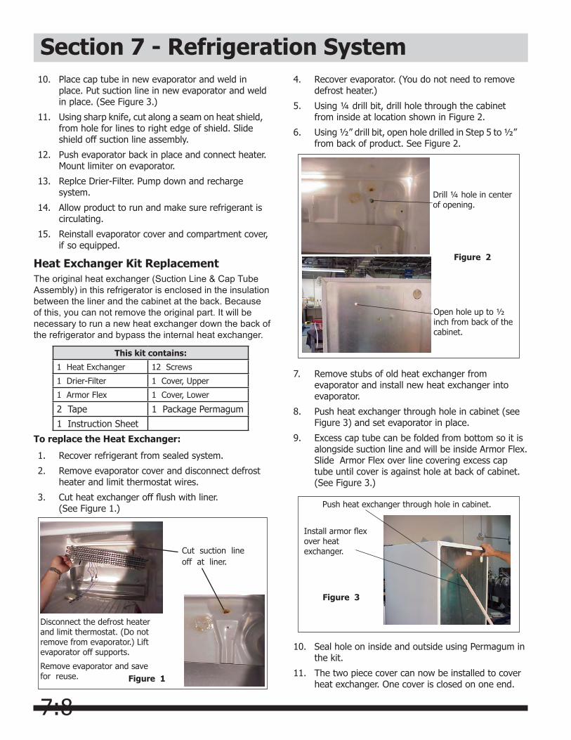
7:8
10. Place cap tube in new evaporator and weld in place. Put suction line in new evaporator and weld in place. (See Figure 3.)
11. Using sharp knife, cut along a seam on heat shield, from hole for lines to right edge of shield. Slide shield off suction line assembly.
12. Push evaporator back in place and connect heater. Mount limiter on evaporator.
13. Replce Drier-Filter. Pump down and recharge system.
14. Allow product to run and make sure refrigerant is circulating.
15. Reinstall evaporator cover and compartment cover, if so equipped.
Heat Exchanger Kit ReplacementThe original heat exchanger (Suction Line & Cap Tube Assembly) in this refrigerator is enclosed in the insulation between the liner and the cabinet at the back. Because of this, you can not remove the original part. It will be necessary to run a new heat exchanger down the back of the refrigerator and bypass the internal heat exchanger.
To replace the Heat Exchanger:
1. Recover refrigerant from sealed system.
2. Remove evaporator cover and disconnect defrost heater and limit thermostat wires.
3. Cut heat exchanger off flush with liner. (See Figure 1.)
4. Recover evaporator. (You do not need to remove defrost heater.)
5. Using ¼ drill bit, drill hole through the cabinet from inside at location shown in Figure 2.
6. Using ½” drill bit, open hole drilled in Step 5 to ½” from back of product. See Figure 2.
Figure 1
Cut suction lineoff at liner.
Disconnect the defrost heater and limit thermostat. (Do not remove from evaporator.) Lift evaporator off supports.
Remove evaporator and save for reuse.
Figure 2
Drill ¼ hole in center of opening.
Open hole up to ½ inch from back of the cabinet.
7. Remove stubs of old heat exchanger from evaporator and install new heat exchanger into evaporator.
8. Push heat exchanger through hole in cabinet (see Figure 3) and set evaporator in place.
9. Excess cap tube can be folded from bottom so it is alongside suction line and will be inside Armor Flex. Slide Armor Flex over line covering excess cap tube until cover is against hole at back of cabinet. (See Figure 3.)
Figure 3
Push heat exchanger through hole in cabinet.
Install armor flex over heat exchanger.
This kit contains:
1 Heat Exchanger 12 Screws
1 Drier-Filter 1 Cover, Upper
1 Armor Flex 1 Cover, Lower
2 Tape 1 Package Permagum
1 Instruction Sheet
Section 7 - Refrigeration System
10. Seal hole on inside and outside using Permagum in the kit.
11. The two piece cover can now be installed to cover heat exchanger. One cover is closed on one end.
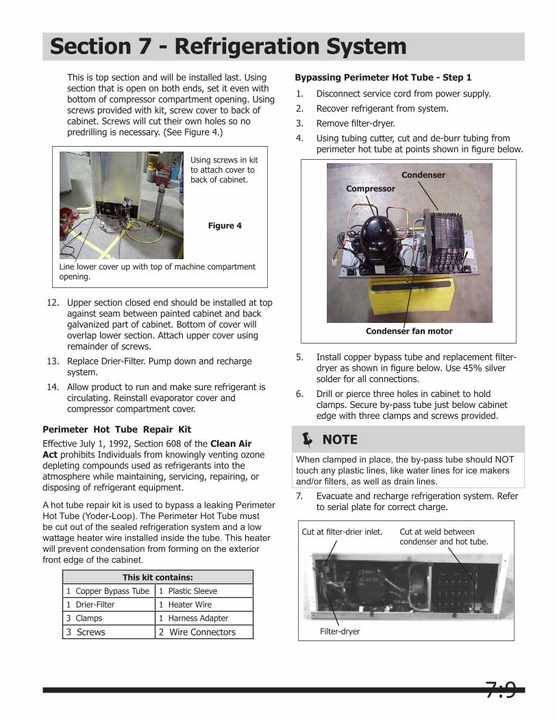
7:9
Section 7 - Refrigeration System
Figure 4
Line lower cover up with top of machine compartment opening.
Using screws in kit to attach cover to back of cabinet.
12. Upper section closed end should be installed at top against seam between painted cabinet and back galvanized part of cabinet. Bottom of cover will overlap lower section. Attach upper cover using remainder of screws.
13. Replace Drier-Filter. Pump down and recharge system.
14. Allow product to run and make sure refrigerant is circulating. Reinstall evaporator cover and compressor compartment cover.
Perimeter Hot Tube Repair KitEffective July 1, 1992, Section 608 of the Clean Air Act prohibits Individuals from knowingly venting ozone depleting compounds used as refrigerants into the atmosphere while maintaining, servicing, repairing, or disposing of refrigerant equipment.
A hot tube repair kit is used to bypass a leaking Perimeter Hot Tube (Yoder-Loop). The Perimeter Hot Tube must be cut out of the sealed refrigeration system and a low wattage heater wire installed inside the tube. This heater will prevent condensation from forming on the exterior front edge of the cabinet.
This is top section and will be installed last. Using section that is open on both ends, set it even with bottom of compressor compartment opening. Using screws provided with kit, screw cover to back of cabinet. Screws will cut their own holes so no predrilling is necessary. (See Figure 4.)
This kit contains:
1 Copper Bypass Tube 1 Plastic Sleeve
1 Drier-Filter 1 Heater Wire
3 Clamps 1 Harness Adapter
3 Screws 2 Wire Connectors
Bypassing Perimeter Hot Tube - Step 1
1. Disconnect service cord from power supply.
2. Recover refrigerant from system.
3. Remove filter-dryer.
4. Using tubing cutter, cut and de-burr tubing from perimeter hot tube at points shown in figure below.
Condenser
Compressor
Condenser fan motor
5. Install copper bypass tube and replacement filter- dryer as shown in figure below. Use 45% silver solder for all connections.
6. Drill or pierce three holes in cabinet to hold clamps. Secure by-pass tube just below cabinet edge with three clamps and screws provided.
Cut at filter-drier inlet. Cut at weld between condenser and hot tube.
Filter-dryer
NOTEWhen clamped in place, the by-pass tube should NOT touch any plastic lines, like water lines for ice makers and/or filters, as well as drain lines.7. Evacuate and recharge refrigeration system. Refer
to serial plate for correct charge.
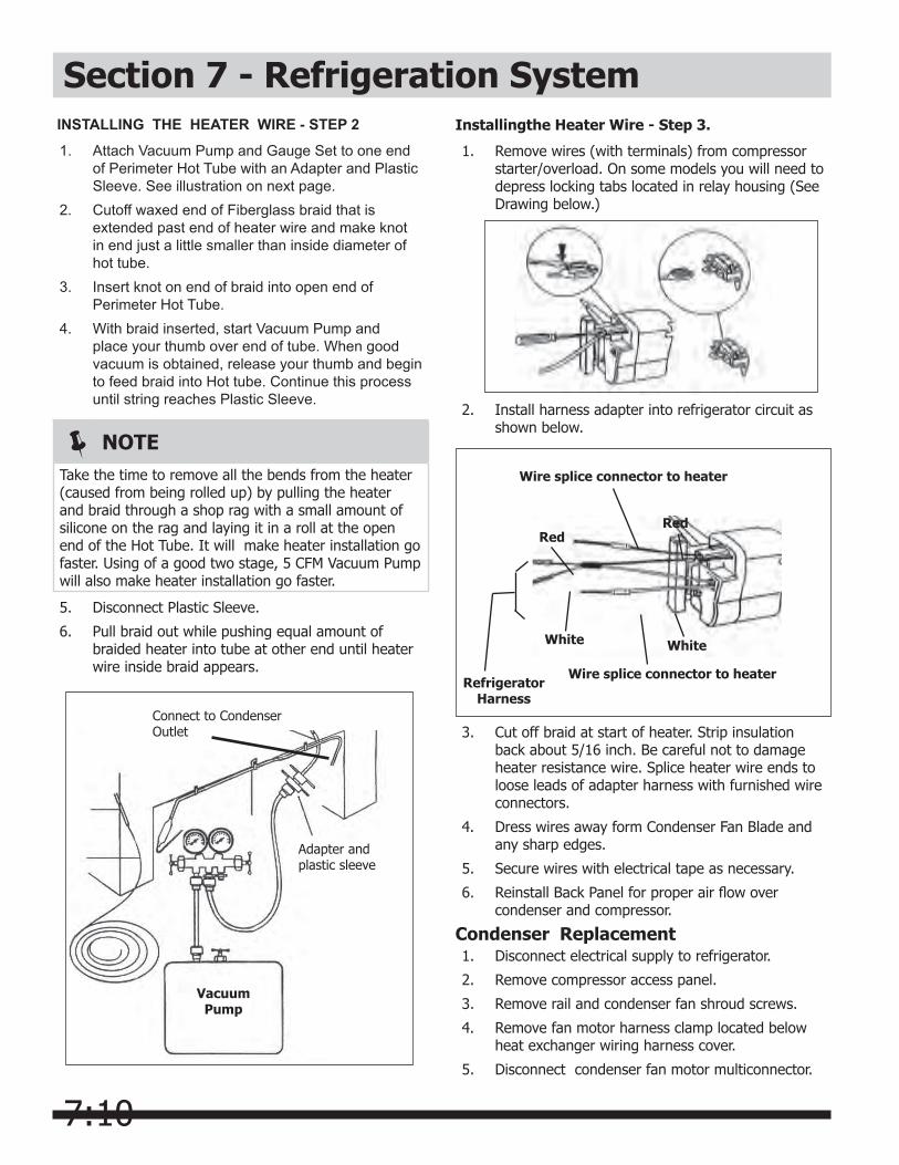
7:10
Installingthe Heater Wire - Step 3.
1. Remove wires (with terminals) from compressor starter/overload. On some models you will need to depress locking tabs located in relay housing (See Drawing below.)
3. Cut off braid at start of heater. Strip insulation back about 5/16 inch. Be careful not to damage heater resistance wire. Splice heater wire ends to loose leads of adapter harness with furnished wire connectors.
4. Dress wires away form Condenser Fan Blade and any sharp edges.
5. Secure wires with electrical tape as necessary.
6. Reinstall Back Panel for proper air flow over condenser and compressor.
Wire splice connector to heater
Wire splice connector to heater
Red
RefrigeratorHarness
Red
White White
NOTETake the time to remove all the bends from the heater (caused from being rolled up) by pulling the heater and braid through a shop rag with a small amount of silicone on the rag and laying it in a roll at the open end of the Hot Tube. It will make heater installation go faster. Using of a good two stage, 5 CFM Vacuum Pump will also make heater installation go faster.
Section 7 - Refrigeration System
Vacuum Pump
Connect to CondenserOutlet
Adapter andplastic sleeve
INSTALLING THE HEATER WIRE - STEP 2
1. Attach Vacuum Pump and Gauge Set to one end of Perimeter Hot Tube with an Adapter and Plastic Sleeve. See illustration on next page.
2. Cutoff waxed end of Fiberglass braid that is extended past end of heater wire and make knot in end just a little smaller than inside diameter of hot tube.
3. Insert knot on end of braid into open end of Perimeter Hot Tube.
4. With braid inserted, start Vacuum Pump and place your thumb over end of tube. When good vacuum is obtained, release your thumb and begin to feed braid into Hot tube. Continue this process until string reaches Plastic Sleeve.
5. Disconnect Plastic Sleeve.
6. Pull braid out while pushing equal amount of braided heater into tube at other end until heater wire inside braid appears.
2. Install harness adapter into refrigerator circuit as shown below.
Condenser Replacement1. Disconnect electrical supply to refrigerator.
2. Remove compressor access panel.
3. Remove rail and condenser fan shroud screws.
4. Remove fan motor harness clamp located below heat exchanger wiring harness cover.
5. Disconnect condenser fan motor multiconnector.

7:11
Section 7 - Refrigeration System6. Pull compressor assembly straight out.
7. Recover refrigerant, using an EPA approved recovery system.
8. Remove wiring from compressor.
1. Disconnect electrical supply to refrigerator.
2. Recover refrigerant by using EPA approved recovery system.
3. Using three cornered file, score groove around capillary tube as close to old filter-drier as possible. Break capillary tube along score mark from filter- drier.
4. Cut condenser outlet tube at filter-drier. Discard filter-drier.
5. Thoroughly clean condenser outlet tube and capillary tube.
6. Place inlet connection of filter-drier over condenser tube approximately ¼” and solder.
7. Insert capillary tube input end into filter-drier outlet. Do not allow tube to bottom against screen. Solder carefully so that solder does not plug capillary tube.
8. Install process tube adaptor to filter-drier.
9. Evacuate and charge system using recommended procedure described under Evacuating and Recharging.
10. Reassemble unit.
9. After refrigerant is completely recovered, disconnect suction and discharge lines from compressor.
10. Pull the condenser straight up and out of the 4 rubber grommet’s holding it to retainer in the base plate.
11. Install the grommet’s on the new condenser and Install replacement condenser in the base plate.
12. Remove original filter-drier.
CAUTIONDONOTunbrazetheoldfilter-drierfromthesystem. This will vaporize and drive moisture from the desiccant back into the system. The old filter-driershouldbecutoutofthesystem.
13. Install new filter-drier at condenser outlet.
14. Evacuate and charge the system using recom- mended procedure described under Evacuating and Recharging.
15. Reassemble unit.
Suction Line And Capillary Tube ReplacementFollow the same procedure used for evaporator replacement.
Filter-Drier InstallationAny time the sealed system is opened and the refrigerant charge is removed, the liquid line filter-drier must be replaced and the system thoroughly evacuated before recharging.
CAUTIONDONOTunbrazetheoldfilter-drierfromthesystem. This will vaporize and drive moisture from the desiccant back into the system. The old filter-driershouldbecutoutofthesystem.
CAUTIONUseonlya15gramXH9liquidlinefilter-drier(part number 5303305677) when servicing refrigeratorandfreezersystems.Thisfilter-drier is compatible with either R-12 or R-134a refrigerant.
Evacuating and Recharging
CAUTIONCheck the serial plate for the correct refrigerant type. It is extremely important to verify the type of refrigerant in the system before starting any sealed system repairs.
CAUTIONWith the possible exception of the vacuum pump, all service equipment that comes in contact with R-134a during evacuation and recharging must be dedicated. Accordingly, R-134a will require a dedicated charging cylinder, manifold gauge set, process tube adaptors, and hoses. Any residual mineral oil on other tools (tubing cutter, etc.) must be thoroughly cleaned off before using on R-134a/Ester oil systems. It will be necessary to check with the manufacturer of your vacuum pump for refrigerant and oil compatibility issues.

7:12
Equipment Needed for Evacuation & Recharging:• Heated charging cylinder
• Standard 3-port manifold gauge set:
- 4 charging hoses
- Tee fitting with valve core stem removed (Robinair No. 40396)
- Hand shut-off valve (Robinair No.40380)
• Two stage vacuum pump
• Process tube adapter kit (Robinair No. 12458)
• Tubing cutter
• Pinch-off tool capable of making leak proof seal
• Complete brazing torch set
• Small 3-corner file
• Grit cloth or Scotch-Brite
• 45% silver solder and flux
• Heat Gun
Installing Evacuation and Recharging Equipment1. Disconnect refrigerator from electrical supply.
2. If compressor was replaced, install correct sized process tube adaptor on process tube. If compressor was not replaced, cut process tube with tubing cutter leaving as much tube
To achieve the required levels of evacuation, a properly maintained two stage vacuum pump in good condition is required. It is absolutely essential to maintain your vacuum pump according to the manufacturer’s instructions including required oil changes at the recommended intervals. Vacuum pump oil should always be changed after evacuating a contaminated system.
Vacuum pump performance should be checked periodically with a micron gauge.
1. Make certain that charging cylinder valve, hand shut-off valve, and manifold gauge valves are closed.
2. Start vacuum pump.
3. Open hand shut-off valve and slowly open both manifold valves, turning counterclockwise, for two full rotations.
WARNINGR-134a systems are particularly susceptible to moisture contamination which can only be prevented by evacuating the system for a minimum of 30 minutes to attain a minimum 29.9 inch (500 micron or lower) vacuum.
CAUTIONIf high vacuum equipment is used, just crack both manifold valves for a few minutes and then open slowly for the two full turns counterclockwise. This will prevent the compressor oil from foaming and being drawn into the vacuum pump.
Section 7 - Refrigeration System
CAUTIONIf you use a vacuum pump with mineral oil to evacuate an R-134a system, it is ABSOLUTELY ESSENTIAL to have a shut-off valve between the pump and your manifold gauge set as shown on page Figure E2. The hand valve must be closed during all times when the vacuum pump is not operating. This will prevent the migration of mineral oil vapor into the R134a/Ester oil system. If the vacuum pump should stop during evacuation for any reason, the hand pump shut-off valve must be closed immediately.
CAUTIONInsure that your refrigeration hoses are specifiedforusewithR-134arefrigerant.Research has shown that compounds in standard refrigeration hoses may enter sealed systems and ultimately restrict the cap tube in an R-134a system.
as possible and install correct size process tube adaptor.
3. Install correct sized process tube adaptor on high-side process tube.
4. Attach refrigeration service gauge manifold to system in following order:
• Low-side (compound gauge) hose to suction side process tube adaptor.
• High-side (pressure gauge) hose to high-side process tube adaptor.
• Center port manifold hose before hand shut-off valve to charging cylinder.
• Center port manifold hose after hand shut-off valve to vacuum pump.
Evacuating System

7:13
Section 7 - Refrigeration System4. Operate the vacuum pump for a minimum of 30
minutes to a minimum of 29.9” (500 micron) vacuum.
5. Close hand shut-off valve to vacuum pump. Watch compound gauge for several minutes. If reading rises, there is leak in system, go to step 6. If no leak is indicated, stop vacuum pump. System is now ready for charging.
6. If leak is indicated, stop vacuum pump and introduce small charge of refrigerant into system by cracking valve on bottom of charging cylinder until system is pressurized to 40 or 50 lbs, psig.
7. Leak test low-side. Close compound gauge. Run compressor for few minutes and leak test high- side. When leak is found, recapture refrigerant using EPA approved recovery system, repair and go back to step 1.
Charging The System
CAUTIONCheck the serial plate for the correct refrigerant type. It is extremely important to verify the type of refrigerant in the system before starting any sealed system repairs.
CAUTIONAfter charging the system with liquid, be certain to wait at least 5 minutes before starting the compressor to give the refrigerant a chance to disperse throughout the system. Otherwise, the compressor could be damaged by attempting to pump excessive quantities of liquid.
Preparing The Charging Cylinder:
1. Make certain that hand shut-off valve to vacuum pump is closed.
2. Close high-side manifold gauge valve.
3. Set charging cylinder scale to pressure indicated on cylinder pressure gauge.
4. Observe refrigerant level in sight glass. Subtract amount to be charged into system and note shut off point.
5. Open charging cylinder valve slowly and allow proper charge to enter system.
6. As soon as refrigerant in sight glass has gone down to predetermined level, close charging cylinder valve.
7. Allow system to sit for five minutes.
8. Turn on refrigerator compressor. Run compressor for few minutes and monitor system pressures.
9. When satisfied that unit is operating correctly, clamp high-side process tube with pinchoff tool while unit is still running.
10. Slowly open high-side manifold gauge valve to allow compressor to remove any refrigerant trapped in high-side hose and process fitting.
11. Close both manifold gauge valves. If high-side gauge reading rises, pinch-off must be corrected before proceeding.
12. Remove high-side process tube adaptor and solder process tube closed.
13. Clamp low-side process tube with pinchoff tool while unit is running. Remove low-side process tube adaptor and solder process tube closed.
14. Check process tubes for refrigerant leaks.
Final Leak Test
1. With refrigerator turned OFF, leak test all low-side system components.
2. Turn unit ON and run until condenser is warm. Leak test high-side system components.
WARNINGDisconnect the charging cylinder heater at this time to prevent the cylinder pressure from exceeding its maximum limits.
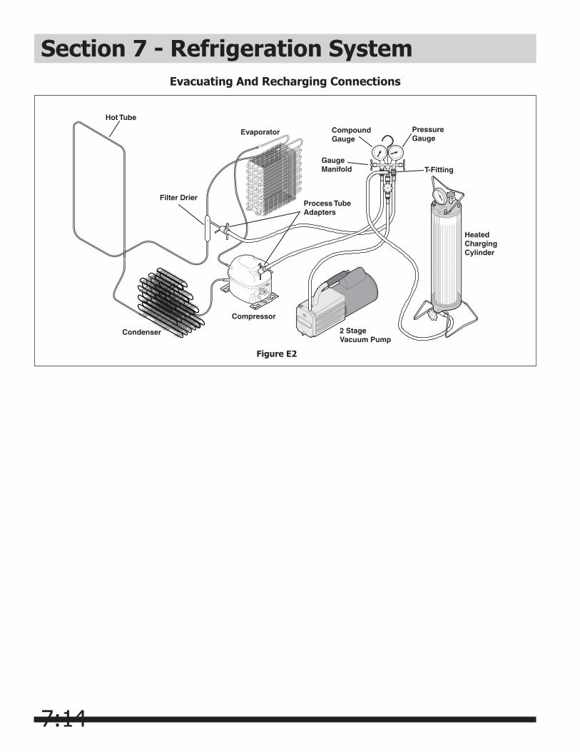
7:14
Evacuating And Recharging Connections
Figure E2
Hot Tube
Evaporator
Condenser
Compressor
2 StageVacuum Pump
HeatedChargingCylinder
Process TubeAdapters
Filter Drier
PressureGauge
CompoundGauge
GaugeManifold T-Fitting
Section 7 - Refrigeration System

7:15
Section 7 - R-134a Service Information
Verify Refrigerant Type in the System
For example, hoses that were used for a refrigeration system operating on R-12 may contain small quantities of mineral oil which can block the capillary tube in a system operating on R-134a. As little as one milligram may be sufficient to cause a blockage. In addition, sealed system components that have been used with CFC systems must not be used with R-134a systems. These components may contain residual amounts of refrigerant and oil which could damage an R-134a system.
At the earliest stage of development work on R-134a, tests were carried out on a different type of synthetic oil known as Poly-Alkaline Glycol (PAG). This oil is also used in certain air conditioning systems for cars. PAG and Ester oil DO NOT mix with one another. Service equipment used for R-134a / Ester oil must not come into contact with PAG.
Dedicated EquipmentR-134a must not be mixed with other types of refrigerants. R-134a must be recovered in dedicated and properly identified recovery bags and tanks.
It will be necessary to check with the manufacturer of your recovery equipment to determine R-134a compatibility. Some recovery equipment manufacturers have changeover instructions for switching between refrigerant types. Protect yourself and your equipment by following all manufacturer guidelines.
Also, ensure that your refrigeration hoses are specified for use with R-134a refrigerant. Research has shown that compounds in standard refrigeration hoses may enter sealed systems and ultimately restrict the cap tube in an R-134a system.
R-134a Refrigeration SystemsThe sealed refrigeration system will consist of the same basic components being utilized in the R-12 systems.
There is a 10% to 15% discharge pressure increase using R-134a, with a 5% to 10% decrease in suction pressure when compared to the same product with an R-12 system operating at 90°F (32°C) ambient temperature conditions. Lower suction pressures result from the lower density of R-134a refrigerant which effects refrigerant flow rate. R-134a systems commonly operate in a 1”-2” vacuum on the suction side.
Products using R-134a refrigerant will generally have a longer capillary tube to maintain a similar flow rate and some models will have a larger condenser to reduce
the discharge pressures and lower start-up sound transmission.
Miscibility of R-134a and Ester OilA special synthetic oil known as Ester oil is used as a lubricant in refrigeration systems operating on R-134a. Ester oils are produced from alcohols and fatty acids and are available in several different variants. Ester oils have a pleasant aroma reminiscent of fruit.
Ester oils generally include various types of additives for improving certain properties such as viscosity, temperature sensitivity, etc. These additives are often aggressive, and skin contact with Ester oils should therefore be avoided.
One of the most important requirements made on a refrigerant system is that the oil mix with the refrigerant. Since mineral oil and ordinary synthetic oil DO NOT mix with R-134a, Ester oil is used for lubrication. Ester oil dissolves in R-134a.
Ester oil is broken down by chlorine and cannot be used with R-12 (R-12 contains chlorine) or any other compound containing chlorine. Therefore, R-134a refrigeration systems have virtually no tolerance for chlorine molecules from CFC refrigerants (R-134a is an HFC and contains no chlorine).
NOTICEInstructions given here are furnished as a guide. Persons attempting to use these instructions to make repairs to the sealed refrigeration system should have a working knowledge of refrigeration and previous training on sealed system repair.
CAUTIONR-134a and R-12 are completely incompatible. Before starting any sealed system repair, it is extremely important to check serial plate of product to verify the type of refrigerant in the system.
CAUTIONDuring R-134a service, it is extremely important to avoid using equipment that may contain residual amounts of mineral oil, CFC’s or HCFC’s which could enter and contaminate the sealed system.
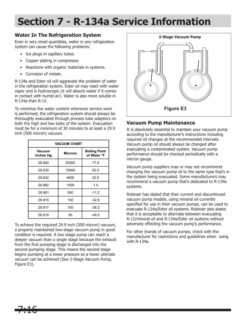
7:16
Section 7 - R-134a Service InformationWater In The Refrigeration SystemEven in very small quantities, water in any refrigeration system can cause the following problems:
• Ice plugs in capillary tubes.
• Copper plating in compressor.
• Reactions with organic materials in systems.
• Corrosion of metals.
R-134a and Ester oil will aggravate the problem of water in the refrigeration system. Ester oil may react with water vapor and is hydroscopic (it will absorb water if it comes in contact with humid air). Water is also more soluble in R-134a than R-12.
To minimize the water content whenever service work is performed, the refrigeration system should always be thoroughly evacuated through process tube adaptors on both the high and low sides of the system. Evacuation must be for a minimum of 30 minutes to at least a 29.9 inch (500 micron) vacuum.
To achieve the required 29.9 inch (500 micron) vacuum, a properly maintained two-stage vacuum pump in good condition is required. A two stage pump can reach a deeper vacuum than a single stage because the exhaust from the first pumping stage is discharged into the second pumping stage. This means the second stage begins pumping at a lower pressure so a lower ultimate vacuum can be achieved (See 2-Stage Vacuum Pump, Figure E3).
VACUUM CHART
Vacuum Inches Hg. Microns Boiling Point
of Water °F
28.940 25000 77.9
29.530 10000 52.0
29.832 4600 32.0
29.882 1000 1.0
29.901 500 -11.2
29.915 150 -32.8
29.917 100 -38.2
29.919 50 -49.0
Vacuum Pump MaintenanceIt is absolutely essential to maintain your vacuum pump according to the manufacturer’s instructions including required oil changes at the recommended intervals. Vacuum pump oil should always be changed after evacuating a contaminated system. Vacuum pump performance should be checked periodically with a micron gauge.
Vacuum pump suppliers may or may not recommend changing the vacuum pump oil to the same type that’s in the system being evacuated. Some manufacturers may recommend a vacuum pump that’s dedicated to R-134a systems.
Robinair has stated that their current and discontinued vacuum pump models, using mineral oil currently specified for use in their vacuum pumps, can be used to evacuate R-134a/Ester oil systems. Robinair also states that it is acceptable to alternate between evacuating R-12/mineral oil and R-134a/Ester oil systems without adversely effecting the vacuum pump’s performance.
For other brands of vacuum pumps, check with the manufacturer for restrictions and guidelines when using with R-134a.
2-Stage Vacuum Pump
Figure E3
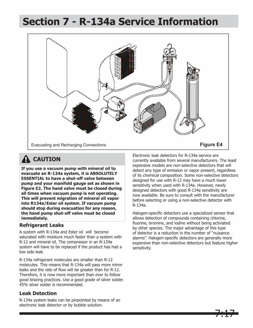
7:17
Section 7 - R-134a Service Information
Refrigerant LeaksA system with R-134a and Ester oil will become saturated with moisture much faster than a system with R-12 and mineral oil. The compressor in an R-134a system will have to be replaced if the product has had a low side leak.
R-134a refrigerant molecules are smaller than R-12 molecules. This means that R-134a will pass more minor leaks and the rate of flow will be greater than for R-12. Therefore, it is now more important than ever to follow good brazing practices. Use a good grade of silver solder. 45% silver solder is recommended.
Leak DetectionR-134a system leaks can be pinpointed by means of an electronic leak detector or by bubble solution.
CAUTIONIf you use a vacuum pump with mineral oil to evacuate an R-134a system, it is ABSOLUTELY ESSENTIAL to have a shut-off valve between pump and your manifold gauge set as shown in Figure E2. The hand valve must be closed during all times when vacuum pump is not operating. This will prevent migration of mineral oil vapor into R134a/Ester oil system. If vacuum pump should stop during evacuation for any reason, the hand pump shut-off valve must be closed immediately.
Evacuating and Recharging Connections Figure E4
Electronic leak detectors for R-134a service are currently available from several manufacturers. The least expensive models are non-selective detectors that will detect any type of emission or vapor present, regardless of its chemical composition. Some non-selective detectors designed for use with R-12 may have a much lower sensitivity when used with R-134a. However, newly designed detectors with good R-134a sensitivity are now available. Be sure to consult with the manufacturer before selecting or using a non-selective detector with R-134a.
Halogen-specific detectors use a specialized sensor that allows detection of compounds containing chlorine, fluorine, bromine, and iodine without being activiated by other species. The major advantage of this type of detector is a reduction in the number of “nuisance alarms”. Halogen-specific detectors are generally more expensive than non-selective detectors but feature higher sensitivity.
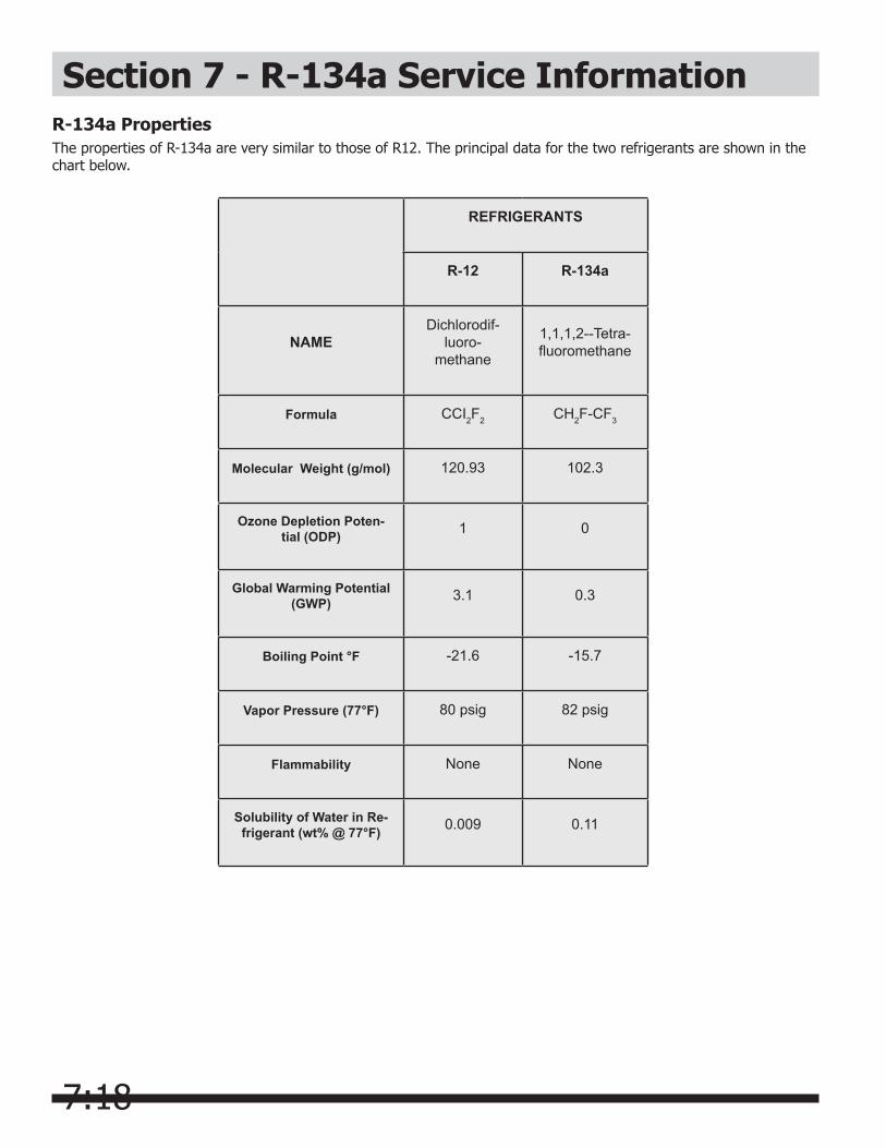
7:18
Section 7 - R-134a Service InformationR-134a PropertiesThe properties of R-134a are very similar to those of R12. The principal data for the two refrigerants are shown in the chart below.
REFRIGERANTS
R-12 R-134a
NAMEDichlorodif-
luoro- methane
1,1,1,2--Tetra- fluoromethane
Formula CCI2F2 CH2F-CF3
Molecular Weight (g/mol) 120.93 102.3
Ozone Depletion Poten-tial (ODP) 1 0
Global Warming Potential (GWP) 3.1 0.3
Boiling Point °F -21.6 -15.7
Vapor Pressure (77°F) 80 psig 82 psig
Flammability None None
Solubility of Water in Re-frigerant (wt% @ 77°F) 0.009 0.11
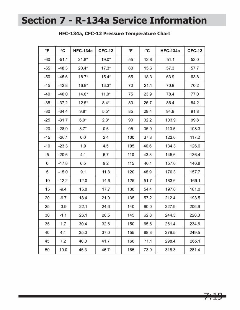
7:19
Section 7 - R-134a Service Information
°F °C HFC-134a CFC-12 °F °C HFC-134a CFC-12
-60 -51.1 21.8* 19.0* 55 12.8 51.1 52.0
-55 -48.3 20.4* 17.3* 60 15.6 57.3 57.7
-50 -45.6 18.7* 15.4* 65 18.3 63.9 63.8
-45 -42.8 16.9* 13.3* 70 21.1 70.9 70.2
-40 -40.0 14.8* 11.0* 75 23.9 78.4 77.0
-35 -37.2 12.5* 8.4* 80 26.7 86.4 84.2
-30 -34.4 9.8* 5.5* 85 29.4 94.9 91.8
-25 -31.7 6.9* 2.3* 90 32.2 103.9 99.8
-20 -28.9 3.7* 0.6 95 35.0 113.5 108.3
-15 -26.1 0.0 2.4 100 37.8 123.6 117.2
-10 -23.3 1.9 4.5 105 40.6 134.3 126.6
-5 -20.6 4.1 6.7 110 43.3 145.6 136.4
0 -17.8 6.5 9.2 115 46.1 157.6 146.8
5 -15.0 9.1 11.8 120 48.9 170.3 157.7
10 -12.2 12.0 14.6 125 51.7 183.6 169.1
15 -9.4 15.0 17.7 130 54.4 197.6 181.0
20 -6.7 18.4 21.0 135 57.2 212.4 193.5
25 -3.9 22.1 24.6 140 60.0 227.9 206.6
30 -1.1 26.1 28.5 145 62.8 244.3 220.3
35 1.7 30.4 32.6 150 65.6 261.4 234.6
40 4.4 35.0 37.0 155 68.3 279.5 249.5
45 7.2 40.0 41.7 160 71.1 298.4 265.1
50 10.0 45.3 46.7 165 73.9 318.3 281.4
HFC-134a, CFC-12 Pressure Temperature Chart
7:20
Section 7 - R-134a Service InformationInhalation ToxicityHFC-134a poses no acute or chronic hazard when it is handled in accordance with DuPont recommendations and when exposures are maintained at or below the DuPont Acceptable Exposure Limit (AEL) of 1,000 ppm (8 and 12 hour Time-Weighted Average or TWA).
An AEL is an airborne exposure limit established by DuPont scientists that specifies time-weighted average (TWA) airborne concentrations to which nearly all workers may be repeatedly exposed without adverse effects. The AEL for HFC-134a has the same value as the Threshold Limit Values (TLVs) established for CFC-12 and HCFC-22. TLVs are established by the American Conference of Governmental and Industrial Hygienists (ACGIH).
However, inhaling high concentrations of HFC-134a vapor may cause temporary central nervous system depression with narcosis, lethargy and anesthetic effects. Other effects that may occur include dizziness, a feeling of intoxication and a loss of coordination. Continued breathing of high concentrations of HFC-134a vapors may produce cardiac irregularities (cardiac sensitization), unconsciousness, and with gross overexposure, death. Intentional misuse or deliberate inhalation of HFC-134a may cause death without warning. This practice is extremely dangerous.
If you experience any of the initial symptoms, move to fresh air and seek medical attention.
Cardiac SensitizationIf vapors are inhaled at a concentration of 75,000 ppm, which is well above the AEL, the heart may become sensitized to adrenaline, leading to cardiac irregularities and, possibly, to cardiac arrest. The likelihood of these cardiac problems increases if you are under physical or emotional stress.
Medical attention must be given immediately if exposed to high concentrations of HFC-134a. DO NOT treat with adrenaline (epinephrine) or similar drugs. These drugs may increase the risk of cardiac arrhythmias and cardiac arrest. If the person is having difficulty breathing, administer oxygen. If breathing has stopped, give artificial respiration.
Spills or LeaksIf a large release of vapor occurs, such as from a large spill or leak, the vapors may concentrate near the floor or low spots and displace the oxygen available for breathing, causing suffocation.
Evacuate everyone until the area has been ventilated.
Use blowers or fans to circulate the air at floor level. DO NOT reenter the affected area unless you are equipped with a self-contained breathing apparatus or unless an area monitor indicates that the concentration of HFC-134a vapors in the area is below the AEL.
Always use self-contained breathing apparatus or an air-line mask when entering tanks or other areas where vapors might exist. Use the buddy system and a lifeline. Refer to the Material Safety Data Sheet (MSDS) for HFC-134a for more information.
HFC-134a vapors have a slightly sweet odor that can be difficult to detect. Therefore, frequent leak checks and the installation of permanent area monitors may be necessary in enclosed spaces. Refer to ASHRAE Standards 15 and 34 for refrigeration machinery rooms.
To ensure safety when working with HFC-134a in enclosed areas:
1. Route relief and purge vent piping (if present) outdoors, away from air intakes.
2. Make certain area is well ventilated, using auxiliary ventilation, if necessary, to move vapors.
3. Make sure area is clear of vapors prior to beginning work.
4. Install air monitoring equipment to detect leaks.
Skin and Eye ContactAt room temperature, HFC-134a vapors have little or no effect on the skin or eyes. However, in liquid form, HFC-134a can freeze skin or eyes on contact, causing frostbite. Following contact, soak the exposed area in lukewarm water, not cold or hot. If medical treatment cannot begin immediately, apply a light coat of a nonmedicated ointment, such as petroleum jelly. If the exposed area is in a location where the presence of the ointment would be awkward, such as on the eye, apply a light bandage. In all cases of frostbite, seek medical attention as soon as possible.
Always wear protective clothing when there is a risk of exposure to liquid HFC-134a. Where splashing is possible, always wear eye protection and a face shield.
Combustibility of HFC-134aHFC-134a is nonflammable at ambient temperatures and atmospheric pressure. However, tests have shown HFC-134a to be combustible at pressures as low as 5.5 psig (139.3 kPa absolute) at 177°C (350°F) when mixed with air at concentrations generally greater than 60% volume air. At lower temperatures, higher pressures are required for combustibility. (HCFC-22 is also combustible at pressures above atmospheric in the presence of high
7:21
Section 7 - R-134a Service Informationair concentrations). Test results and calculations have shown:
• At ambient temperature, all concentrations of HFC-134a in air are nonflammable at pressures below 15 psig (205 kPa absolute).
• Combustible mixtures of air and HFC-134a will not form when liquid HFC-134a is pumped into closed vessel if initial air pressure in vessel is limited to one atmosphere absolute and final pressure is limited to 300 psig (2,170 kPa absolute). If initial air pressure is greater than one atmosphere, combustible mixtures may form as tank is filled.
Based on above information, the following operating practices are recommended:
Leak Testing• Equipment should NEVER be leak tested with a
pressurized mixture of HFC-134a and air. HFC-134a may be safely pressured with dry nitrogen.
Bulk Delivery and Storage• Tanks should normally be evacuated at start of
filling, and should never be filled while under positive air pressure.
• Tank pressure should never be allowed to exceed 300 psig (2,170 kPa) when filling with HFC-134a. Relief devices on either tanks or HFC-134a supply system usually prevent this.
• Tank pressures should be monitored routinely.
• Air lines should never be connected to storage tanks.
Filling and Charging Operations• Before evacuating cylinders or refrigeration
equipment, any remaining refrigerant should be removed by recovery system.
• Vacuum pump discharge lines should be free of restrictions that could increase discharge pressures above 15 psig (205 kPa) and result in formation of combustible mixtures.
• Cylinders or refrigeration equipment should normally be evacuated at start of filling,and should never be filled while under positive air pressure.
• Final pressures should not exceed 300 psig (2,170 kPa).
• Filled cylinders should periodically be analyzed for air (nonabsorbable gas or NAG).
Refrigerant Recovery SystemsEfficient recovery of refrigerant from equipment or containers requires evacuation at the end of the recovery
cycle. Suction lines to a recovery compressor should be periodically checked for leaks to prevent compressing air into the recovery cylinder during evacuation. In addition, the recovery cylinder pressure should be monitored, and evacuation stopped in the event of a rapid pressure rise indicating the presence of noncondensable air. The recovery cylinder contents should then be analyzed for NAG, and the recovery system leak checked if air is present. DO NOT continue to evacuate a refrigeration system that has a major leak.
Thermal DecompositionHFC-134a vapors will decompose when exposed to high temperatures from flames or electric resistance heaters. Decomposition may produce toxic and irritating compounds, such as hydrogen fluoride. The pungent odors released will irritate the nose and throat and generally force people to evacuate the area. Therefore, it is important to prevent decomposition by avoiding exposure to high temperatures.
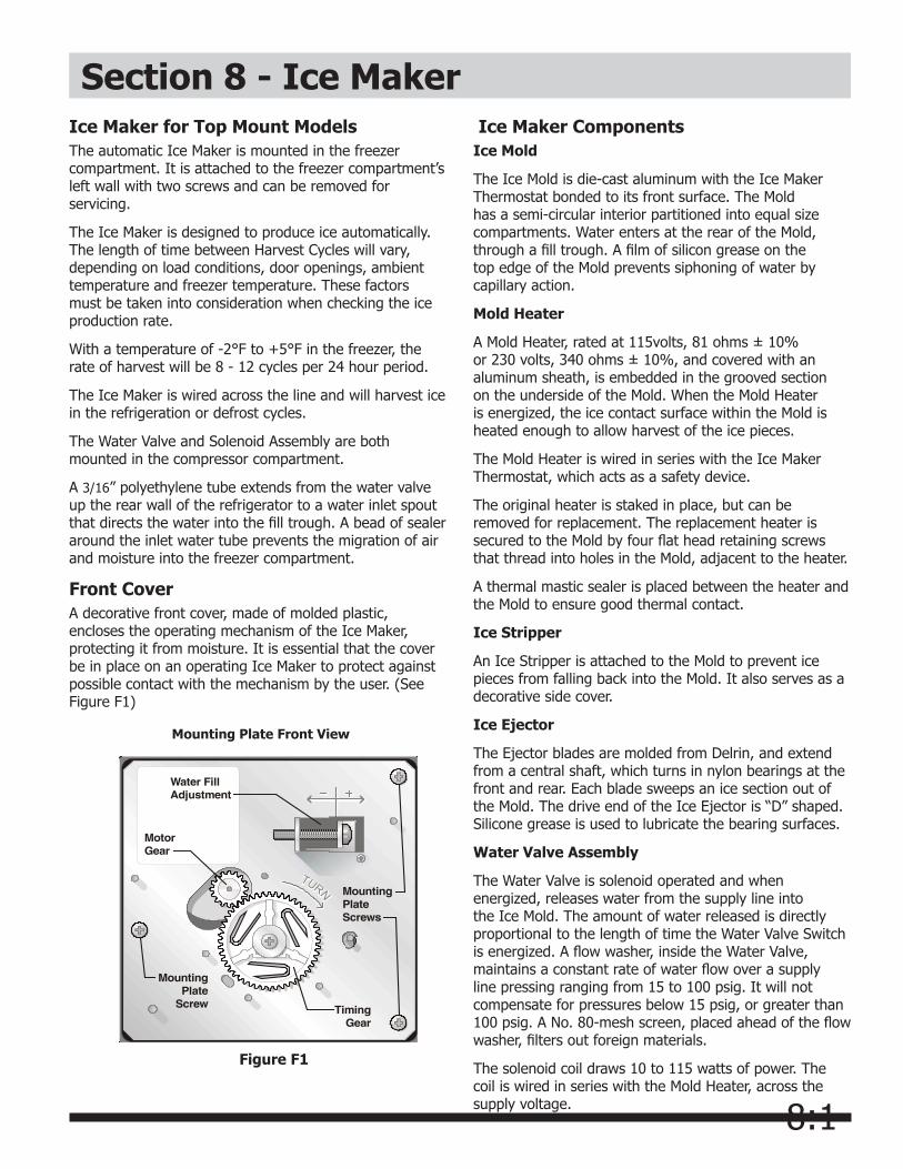
8:1
Section 8 - Ice Maker
Figure F1
Mounting Plate Front View
Ice Maker for Top Mount ModelsThe automatic Ice Maker is mounted in the freezer compartment. It is attached to the freezer compartment’s left wall with two screws and can be removed for servicing.
The Ice Maker is designed to produce ice automatically. The length of time between Harvest Cycles will vary, depending on load conditions, door openings, ambient temperature and freezer temperature. These factors must be taken into consideration when checking the ice production rate.
With a temperature of -2°F to +5°F in the freezer, the rate of harvest will be 8 - 12 cycles per 24 hour period.
The Ice Maker is wired across the line and will harvest ice in the refrigeration or defrost cycles.
The Water Valve and Solenoid Assembly are both mounted in the compressor compartment.
A 3/16” polyethylene tube extends from the water valve up the rear wall of the refrigerator to a water inlet spout that directs the water into the fill trough. A bead of sealer around the inlet water tube prevents the migration of air and moisture into the freezer compartment.
Front Cover A decorative front cover, made of molded plastic, encloses the operating mechanism of the Ice Maker, protecting it from moisture. It is essential that the cover be in place on an operating Ice Maker to protect against possible contact with the mechanism by the user. (See Figure F1)
Ice Maker Components Ice Mold
The Ice Mold is die-cast aluminum with the Ice Maker Thermostat bonded to its front surface. The Mold has a semi-circular interior partitioned into equal size compartments. Water enters at the rear of the Mold, through a fill trough. A film of silicon grease on the top edge of the Mold prevents siphoning of water by capillary action.
Mold Heater
A Mold Heater, rated at 115volts, 81 ohms ± 10% or 230 volts, 340 ohms ± 10%, and covered with an aluminum sheath, is embedded in the grooved section on the underside of the Mold. When the Mold Heater is energized, the ice contact surface within the Mold is heated enough to allow harvest of the ice pieces.
The Mold Heater is wired in series with the Ice Maker Thermostat, which acts as a safety device.
The original heater is staked in place, but can be removed for replacement. The replacement heater is secured to the Mold by four flat head retaining screws that thread into holes in the Mold, adjacent to the heater.
A thermal mastic sealer is placed between the heater and the Mold to ensure good thermal contact.
Ice Stripper
An Ice Stripper is attached to the Mold to prevent ice pieces from falling back into the Mold. It also serves as a decorative side cover.
Ice Ejector
The Ejector blades are molded from Delrin, and extend from a central shaft, which turns in nylon bearings at the front and rear. Each blade sweeps an ice section out of the Mold. The drive end of the Ice Ejector is “D” shaped. Silicone grease is used to lubricate the bearing surfaces.
Water Valve Assembly
The Water Valve is solenoid operated and when energized, releases water from the supply line into the Ice Mold. The amount of water released is directly proportional to the length of time the Water Valve Switch is energized. A flow washer, inside the Water Valve, maintains a constant rate of water flow over a supply line pressing ranging from 15 to 100 psig. It will not compensate for pressures below 15 psig, or greater than 100 psig. A No. 80-mesh screen, placed ahead of the flow washer, filters out foreign materials.
The solenoid coil draws 10 to 115 watts of power. The coil is wired in series with the Mold Heater, across the supply voltage.
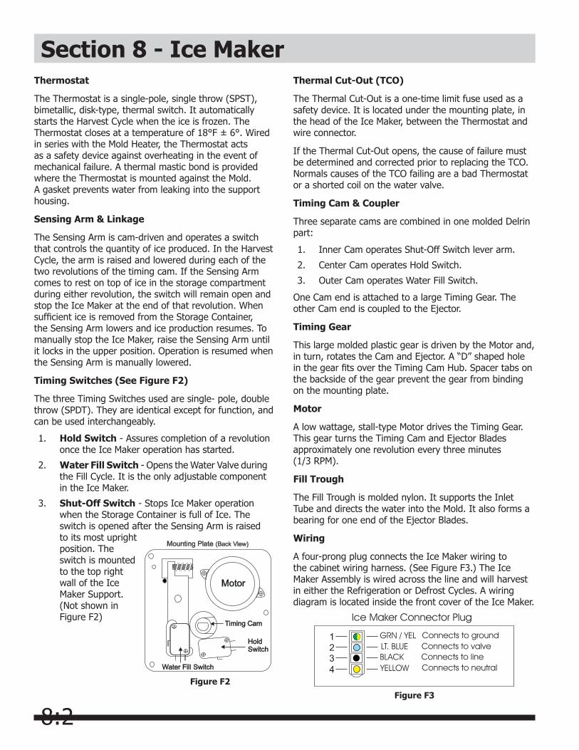
8:2
Section 8 - Ice MakerThermostat
The Thermostat is a single-pole, single throw (SPST), bimetallic, disk-type, thermal switch. It automatically starts the Harvest Cycle when the ice is frozen. The Thermostat closes at a temperature of 18°F ± 6°. Wired in series with the Mold Heater, the Thermostat acts as a safety device against overheating in the event of mechanical failure. A thermal mastic bond is provided where the Thermostat is mounted against the Mold. A gasket prevents water from leaking into the support housing.
Sensing Arm & Linkage
The Sensing Arm is cam-driven and operates a switch that controls the quantity of ice produced. In the Harvest Cycle, the arm is raised and lowered during each of the two revolutions of the timing cam. If the Sensing Arm comes to rest on top of ice in the storage compartment during either revolution, the switch will remain open and stop the Ice Maker at the end of that revolution. When sufficient ice is removed from the Storage Container, the Sensing Arm lowers and ice production resumes. To manually stop the Ice Maker, raise the Sensing Arm until it locks in the upper position. Operation is resumed when the Sensing Arm is manually lowered.
Timing Switches (See Figure F2)
The three Timing Switches used are single- pole, double throw (SPDT). They are identical except for function, and can be used interchangeably.
1. Hold Switch - Assures completion of a revolution once the Ice Maker operation has started.
2. Water Fill Switch - Opens the Water Valve during the Fill Cycle. It is the only adjustable component in the Ice Maker.
3. Shut-Off Switch - Stops Ice Maker operation when the Storage Container is full of Ice. The switch is opened after the Sensing Arm is raised to its most upright position. The switch is mounted to the top right wall of the Ice Maker Support. (Not shown in Figure F2)
Thermal Cut-Out (TCO)
The Thermal Cut-Out is a one-time limit fuse used as a safety device. It is located under the mounting plate, in the head of the Ice Maker, between the Thermostat and wire connector.
If the Thermal Cut-Out opens, the cause of failure must be determined and corrected prior to replacing the TCO. Normals causes of the TCO failing are a bad Thermostat or a shorted coil on the water valve.
Timing Cam & Coupler
Three separate cams are combined in one molded Delrin part:
1. Inner Cam operates Shut-Off Switch lever arm.
2. Center Cam operates Hold Switch.
3. Outer Cam operates Water Fill Switch.
One Cam end is attached to a large Timing Gear. The other Cam end is coupled to the Ejector.
Timing Gear
This large molded plastic gear is driven by the Motor and, in turn, rotates the Cam and Ejector. A “D” shaped hole in the gear fits over the Timing Cam Hub. Spacer tabs on the backside of the gear prevent the gear from binding on the mounting plate.
Motor
A low wattage, stall-type Motor drives the Timing Gear. This gear turns the Timing Cam and Ejector Blades approximately one revolution every three minutes (1/3 RPM).
Fill Trough
The Fill Trough is molded nylon. It supports the Inlet Tube and directs the water into the Mold. It also forms a bearing for one end of the Ejector Blades.
Wiring
A four-prong plug connects the Ice Maker wiring to the cabinet wiring harness. (See Figure F3.) The Ice Maker Assembly is wired across the line and will harvest in either the Refrigeration or Defrost Cycles. A wiring diagram is located inside the front cover of the Ice Maker.
Figure F3
Figure F2

8:3
Installing Water Supply Line to Ice MakerSupply line installation must comply with all applicable plumbing codes. Refer to the Ice Maker Installation Instructions in appendix A.
The ¼” tubing, and any other plumbing materials required, should be obtained locally.
The ice maker should be connected to a frequently used cold water line to ensure a fresh water supply.
Section 8 - Ice Maker
NOTEA vertical cold water line should be selected for the water supply. If a vertical line is not available, a horizontal line may be used, providing the connection is on the side or top of the pipe, but not on the bottom. Scale and foreign material in the pipe could cause stoppage of water flow if the connection is on the bottom.
Be sure to leak test all connections after the water supply has been turned on.
Test Cycling Ice Maker (See Ice Maker Testing Procedures).It may be necessary, on occasion, to test-cycle an Ice Maker to check its operation. This can be done on the repair bench or while mounted in the Refrigerator.
If the Ice Maker is in an operating refrigerator, take precautions against the formation of condensate by allowing the cold, metal components to warm up before removing the front cover. This can be expedited by cycling the assembly with the cover in place and the water supply valve closed.
To manually cycle the Ice Maker, slowly turn the Ejector blades clockwise until the Hold Switch circuit to the Motor is completed. When the Motor starts, all components except the Ice Maker Thermostat should perform normally. Once the Ice Maker completes its cycle, remove the front Cover; see instructions for replacing the front Cover in “To Replace Front Cover” on this page.
If further test cycling is necessary, place screwdriver blade in slot located in the Motor Drive Gear and turn counterclockwise until the Hold Switch circuit to the Motor is completed.
Water Valve Switch – Water Fill VolumeThe amount of water fill is directly proportional to the length of time terminals “C-NC” of the Water Fill Switch are closed. Closing occurs when the switch plunger drops into a cavity formed in the Cam.
Different water valves have different flow rates. For this reason, anytime a Water Valve is replaced, the Water Fill Switch must be adjusted.
The correct water fill volume is 95-105 cc. To measure the fill volume, test-cycle the Ice Maker and collect the water. Measure in a container calibrated in cubic centimeters (cc) or ounces.
The fill volume is adjusted by increasing or decreasing the length of time the Water Fill Switch remains closed.
To adjust the Water Fill Switch, first determine how much water is needed. The adjusting screw is calibrated so that one complete revolution changes the water fill about 18 cubic centimeters. Turning the screw clockwise decreases the fill, while turning counterclockwise increases the fill.
EXAMPLE: An Ice Maker is test-cycled and the water fill sample is 158 cubic centimeters. Subtracting 145 cc from 158, the adjustment needed is 13 cc. Since one turn of the adjusting screw changes the fill 18 cc, ¾ of a turn clockwise would reduce the fill about 13 cc, the desired amount. (This example is for manual models only.)
Parts ReplacementDisconnect electrical supply to refrigerator. If the Refrigerator is operating and cold, allow the Ice Maker to warm up to room temperature before removing the front cover. This prevents moisture from condensing on the metal components.
To Replace Front Cover (See Figure F4)
1. Ensure that Ice Maker is at room temperature before removing Cover.
2. Place straight blade of screwdriver in slot at bottom of Mold Support and pry Cover loose.
3. Snap Cover in place.
NOTEEnsure that the retaining tabs inside the Cover are located on the top and bottom when installing the Cover.
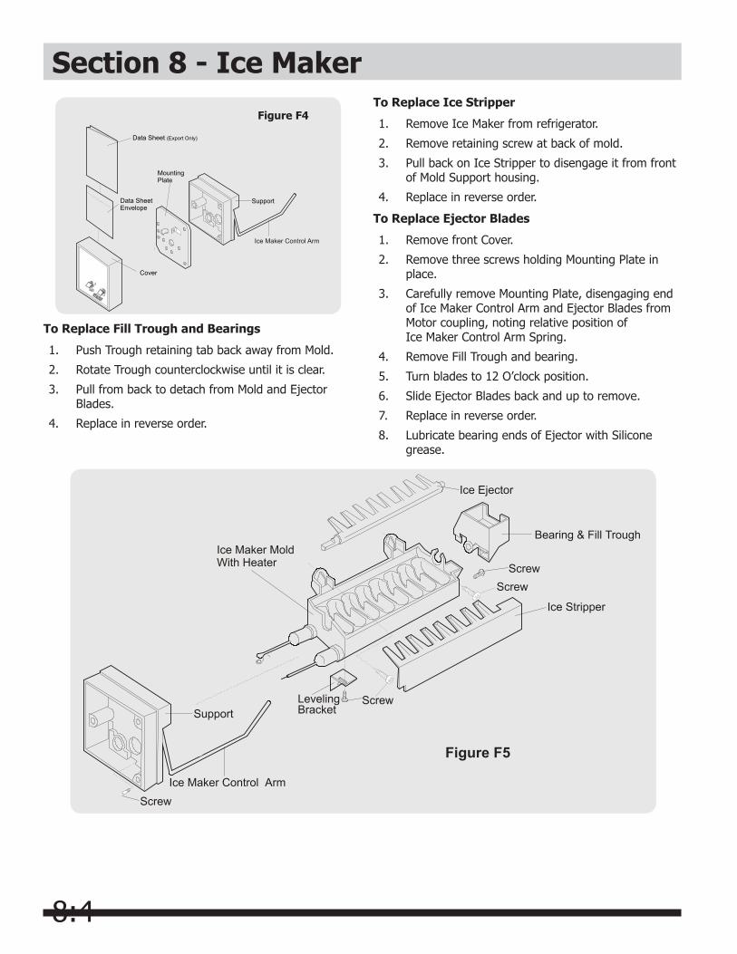
8:4
Section 8 - Ice Maker
Figure F4
Data Sheet (Export Only)
Cover
Support
MountingPlate
Data SheetEnvelope
To Replace Fill Trough and Bearings
1. Push Trough retaining tab back away from Mold.
2. Rotate Trough counterclockwise until it is clear.
3. Pull from back to detach from Mold and Ejector Blades.
4. Replace in reverse order.
To Replace Ice Stripper
1. Remove Ice Maker from refrigerator.
2. Remove retaining screw at back of mold.
3. Pull back on Ice Stripper to disengage it from front of Mold Support housing.
4. Replace in reverse order.
Figure F5
To Replace Ejector Blades
1. Remove front Cover.
2. Remove three screws holding Mounting Plate in place.
3. Carefully remove Mounting Plate, disengaging end of Ice Maker Control Arm and Ejector Blades from Motor coupling, noting relative position of Ice Maker Control Arm Spring.
4. Remove Fill Trough and bearing.
5. Turn blades to 12 O’clock position.
6. Slide Ejector Blades back and up to remove.
7. Replace in reverse order.
8. Lubricate bearing ends of Ejector with Silicone grease.
8:5
Section 8 - Ice MakerTo Replace Motor and Switch Mounting Plate
1 Remove front Cover.
2. Remove three screws that attach Mounting Plate to Support Housing.
3. Carefully remove Mounting Plate, disengaging end of Sweep Arm and noting relative position of Sweep Arm Spring.
4. Transfer Motor, Switches, Cam, Gear, and Water Fill Adjusting Spring and Arm to replacement Mounting Plate.
5. Attach new Mounting Plate to Support Housing with three screws.
6. Check Water Fill Cycle and adjust as required.
7. Replace front Cover.
To Replace Motor
1. Remove front Cover.
2. Remove three screws that attach Mounting Plate to Support Housing.
3. Disconnect two Motor leads.
4. Remove two Motor mounting screws.
5. Replace Motor in reverse order.
To Replace Water Fill Switch
1. Remove front Cover.
2. Remove three screws that attach Mounting Plate to Support Housing.
3. Disconnect two Water Fill Switch wire leads.
4. Remove two switch mounting screws.
5. Remove switch.
6. Replace switch in reverse order, ensuring that switch insulator is in place.
7. Check Water Fill Cycle and adjust as required.
To Replace Hold Switch
1. Remove front Cover.
2. Remove three screws that attach Mounting Plate to Support Housing.
3. Disconnect six Hold Switch wire leads.
4. Remove two Hold Switch mounting screws.
5. Remove Hold Switch.
6. Replace in reverse order.
NOTEEnsure that the wiring harness is properly positioned and the Sweep Arm is in place.
To Replace Ice Maker Control Arm Shut-OFF Switch
1. Remove front Cover.
2. Remove three screws that attach Mounting Plate to Support Housing.
3. Disconnect three Ice Maker Control Arm Shut-Off Switch wire leads.
4. Raise Ice Maker Control Arm Lever.
5. Remove two Ice Maker Control Arm Shut-Off Switch mounting screws.
6. Remove switch.
7. Replace switch in reverse order.
To Replace Ice Maker Thermostat
1. Remove front Cover.
2. Remove three screws that attach Mounting Plate to Support Housing.
3. Loosen two Thermostat retaining clip mounting screws.
4. Disconnect two thermostat wire leads and remove thermostat.
5. Apply thermal mastic sealer to sensing surface of replacement thermostat to ensure a positive bond to mold.
To Replace Thermal Cut-Out (TCO)
1. Remove front Cover.
2. Remove three screws that attach Mounting Plate to Support Housing.
3. Pull cable assembly free from support housing. It will slide out easily.
4. Loosen screw securing clamp to TCO. TCO should come free after tension from clamp is released.
5. Disconnect TCO from two wire nuts. One end is connect to the cable assembly and the other end is connected to the motor and mold heater.
6. Replace with new TCO.
7. Reassemble in reverse order.
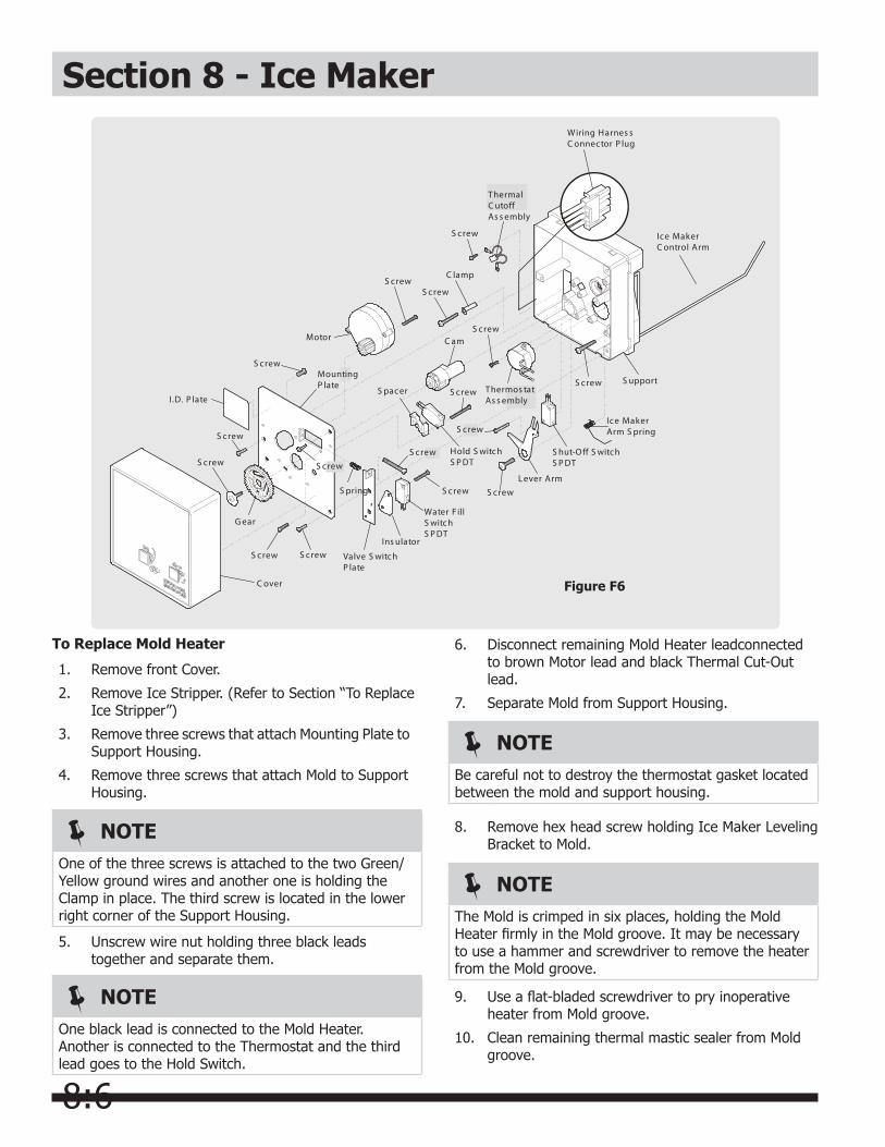
8:6
Section 8 - Ice Maker
NOTEOne of the three screws is attached to the two Green/Yellow ground wires and another one is holding the Clamp in place. The third screw is located in the lower right corner of the Support Housing.
S crew
Motor
S crew
S upport
Ice MakerC ontrol Arm
C am
C lamp
S crew
S crew
S crewS crew
S crew
S crew
I.D. P late
ThermalC utoffAs s embly
S crew
S crew
S crew
S crew Thermos tatAs s embly
S crew
S crew
Hold S witchS P DT
S hut-Off S witchS P DT
Ice MakerArm S pring
Water F illS witchS P DT
Ins ulator
Valve S witchP late
C over
G ear
S crew
MountingP late
S pring
S pacer
L ever ArmS crew
Wiring Harnes sC onnector P lug
Figure F6
To Replace Mold Heater
1. Remove front Cover.
2. Remove Ice Stripper. (Refer to Section “To Replace Ice Stripper”)
3. Remove three screws that attach Mounting Plate to Support Housing.
4. Remove three screws that attach Mold to Support Housing.
5. Unscrew wire nut holding three black leads together and separate them.
NOTEOne black lead is connected to the Mold Heater. Another is connected to the Thermostat and the third lead goes to the Hold Switch.
6. Disconnect remaining Mold Heater leadconnected to brown Motor lead and black Thermal Cut-Out lead.
7. Separate Mold from Support Housing.
NOTEBe careful not to destroy the thermostat gasket located between the mold and support housing.
8. Remove hex head screw holding Ice Maker Leveling Bracket to Mold.
NOTEThe Mold is crimped in six places, holding the Mold Heater firmly in the Mold groove. It may be necessary to use a hammer and screwdriver to remove the heater from the Mold groove.
9. Use a flat-bladed screwdriver to pry inoperative heater from Mold groove.
10. Clean remaining thermal mastic sealer from Mold groove.
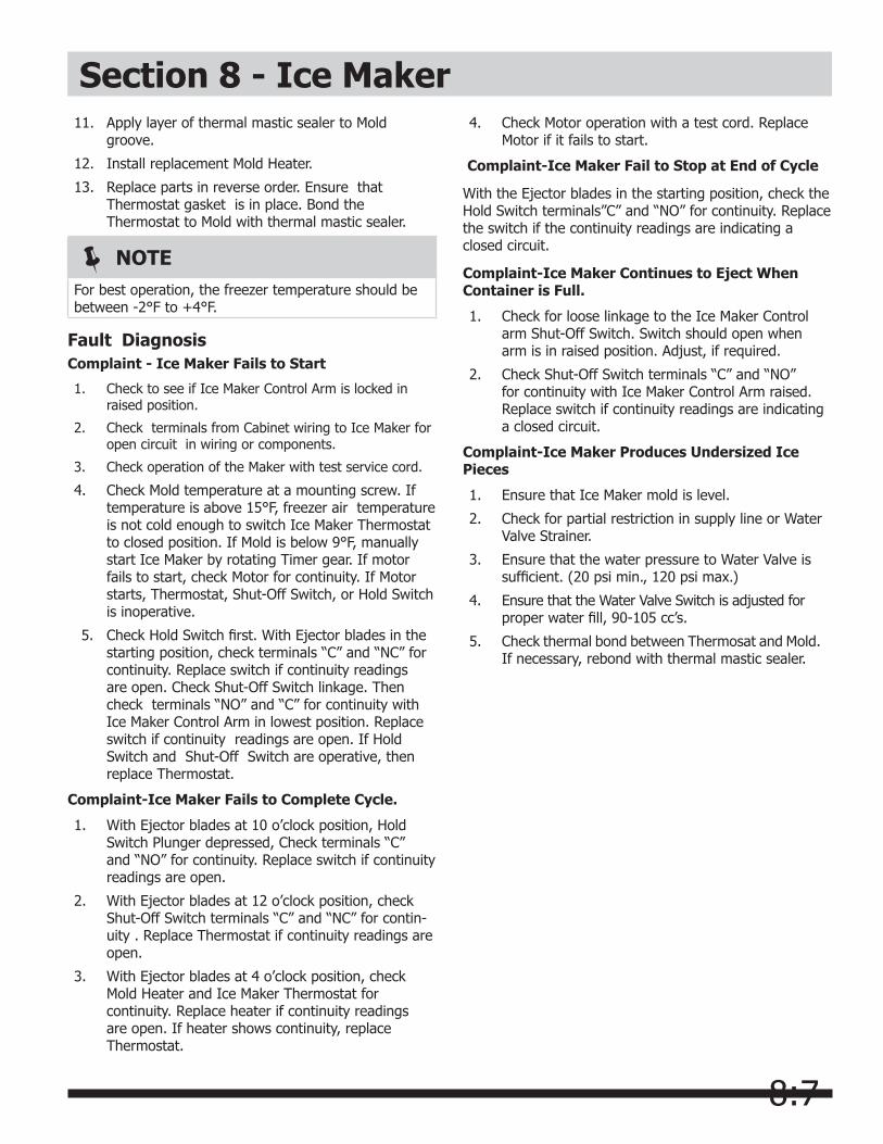
8:7
Section 8 - Ice Maker11. Apply layer of thermal mastic sealer to Mold
groove.
12. Install replacement Mold Heater.
13. Replace parts in reverse order. Ensure that Thermostat gasket is in place. Bond the Thermostat to Mold with thermal mastic sealer.
NOTEFor best operation, the freezer temperature should be between -2°F to +4°F.
Fault DiagnosisComplaint - Ice Maker Fails to Start
1. Check to see if Ice Maker Control Arm is locked in raised position.
2. Check terminals from Cabinet wiring to Ice Maker for open circuit in wiring or components.
3. Check operation of the Maker with test service cord.
4. Check Mold temperature at a mounting screw. If temperature is above 15°F, freezer air temperature is not cold enough to switch Ice Maker Thermostat to closed position. If Mold is below 9°F, manually start Ice Maker by rotating Timer gear. If motor fails to start, check Motor for continuity. If Motor starts, Thermostat, Shut-Off Switch, or Hold Switch is inoperative.
5. Check Hold Switch first. With Ejector blades in the starting position, check terminals “C” and “NC” for continuity. Replace switch if continuity readings are open. Check Shut-Off Switch linkage. Then check terminals “NO” and “C” for continuity with Ice Maker Control Arm in lowest position. Replace switch if continuity readings are open. If Hold Switch and Shut-Off Switch are operative, then replace Thermostat.
Complaint-Ice Maker Fails to Complete Cycle.
1. With Ejector blades at 10 o’clock position, Hold Switch Plunger depressed, Check terminals “C” and “NO” for continuity. Replace switch if continuity readings are open.
2. With Ejector blades at 12 o’clock position, check Shut-Off Switch terminals “C” and “NC” for contin- uity . Replace Thermostat if continuity readings are open.
3. With Ejector blades at 4 o’clock position, check Mold Heater and Ice Maker Thermostat for continuity. Replace heater if continuity readings are open. If heater shows continuity, replace Thermostat.
4. Check Motor operation with a test cord. Replace Motor if it fails to start.
Complaint-Ice Maker Fail to Stop at End of Cycle
With the Ejector blades in the starting position, check the Hold Switch terminals”C” and “NO” for continuity. Replace the switch if the continuity readings are indicating a closed circuit.
Complaint-Ice Maker Continues to Eject When Container is Full.
1. Check for loose linkage to the Ice Maker Control arm Shut-Off Switch. Switch should open when arm is in raised position. Adjust, if required.
2. Check Shut-Off Switch terminals “C” and “NO” for continuity with Ice Maker Control Arm raised. Replace switch if continuity readings are indicating a closed circuit.
Complaint-Ice Maker Produces Undersized Ice Pieces
1. Ensure that Ice Maker mold is level.
2. Check for partial restriction in supply line or Water Valve Strainer.
3. Ensure that the water pressure to Water Valve is sufficient. (20 psi min., 120 psi max.)
4. Ensure that the Water Valve Switch is adjusted for proper water fill, 90-105 cc’s.
5. Check thermal bond between Thermosat and Mold. If necessary, rebond with thermal mastic sealer.
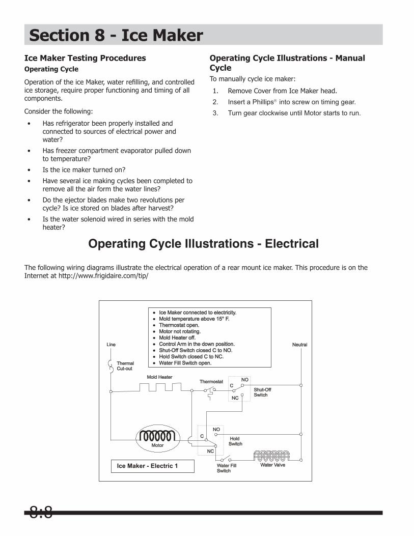
8:8
Ice Maker Testing ProceduresOperating Cycle
Operation of the ice Maker, water refilling, and controlled ice storage, require proper functioning and timing of all components.
Consider the following:
• Has refrigerator been properly installed and connected to sources of electrical power and water?
• Has freezer compartment evaporator pulled down to temperature?
• Is the ice maker turned on?
• Have several ice making cycles been completed to remove all the air form the water lines?
• Do the ejector blades make two revolutions per cycle? Is ice stored on blades after harvest?
• Is the water solenoid wired in series with the mold heater?
Operating Cycle Illustrations - Electrical
Operating Cycle Illustrations - Manual CycleTo manually cycle ice maker:
1. Remove Cover from Ice Maker head.
2. Insert a Phillips into screw on timing gear.3. Turn gear clockwise until Motor starts to run.
The following wiring diagrams illustrate the electrical operation of a rear mount ice maker. This procedure is on the Internet at http://www.frigidaire.com/tip/
Section 8 - Ice Maker
Ice Maker - Electric 1

8:9
Section 8 - Ice Maker
Ice Maker - Electric 2
Ice Maker - Electric 3
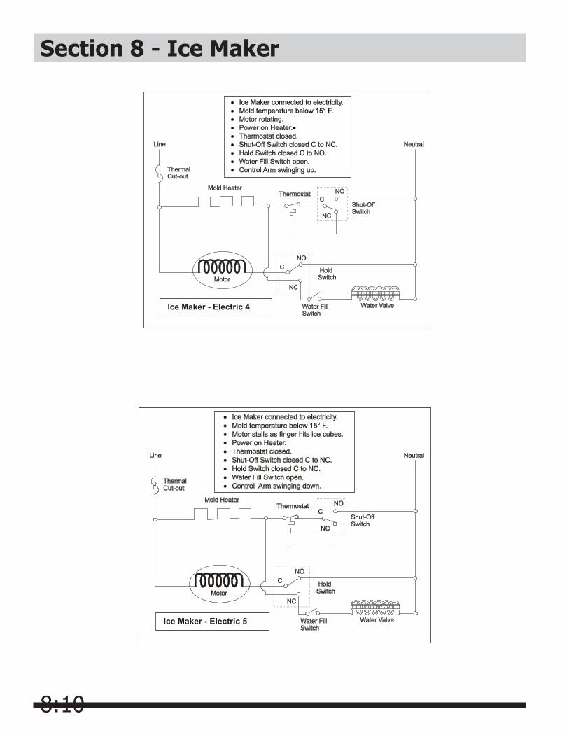
8:10
Section 8 - Ice Maker
Ice Maker - Electric 5
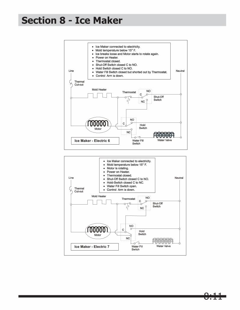
8:11
Section 8 - Ice Maker
Ice Maker - Electric 6
Ice Maker - Electric 7

8:12
Section 8 - Ice Maker
Ice Maker - Electric 8
Ice Maker - Electric 9
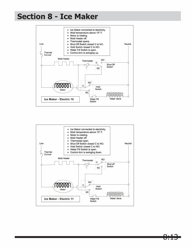
8:13
Section 8 - Ice Maker
Ice Maker - Electric 10
Ice Maker - Electric 11
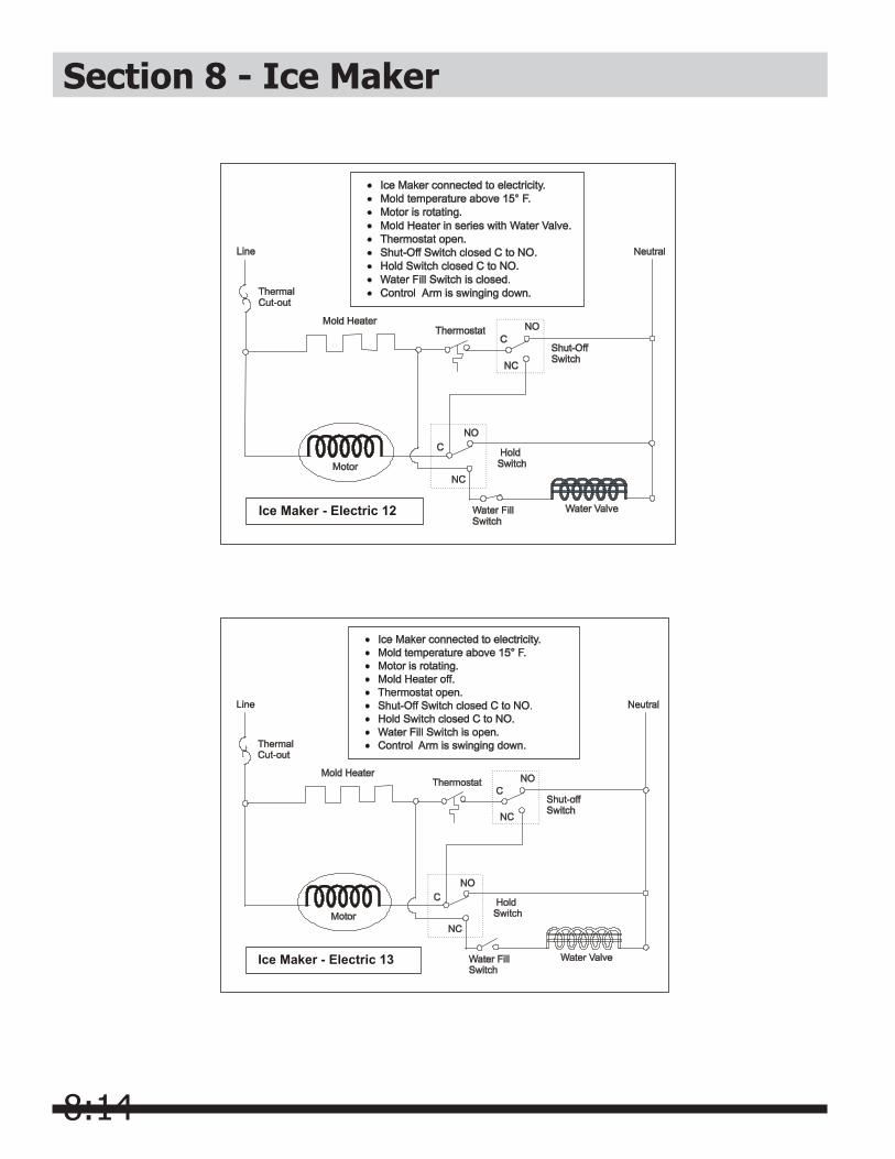
8:14
Ice Maker - Electric 13
Section 8 - Ice Maker
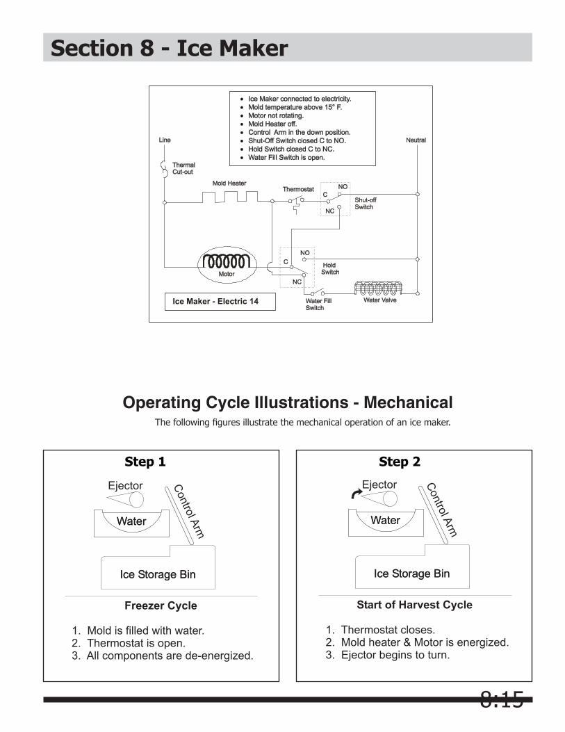
8:15
Step 1
Ice Maker - Electric 14
Section 8 - Ice Maker
Operating Cycle Illustrations - MechanicalThe following figures illustrate the mechanical operation of an ice maker.
Step 2
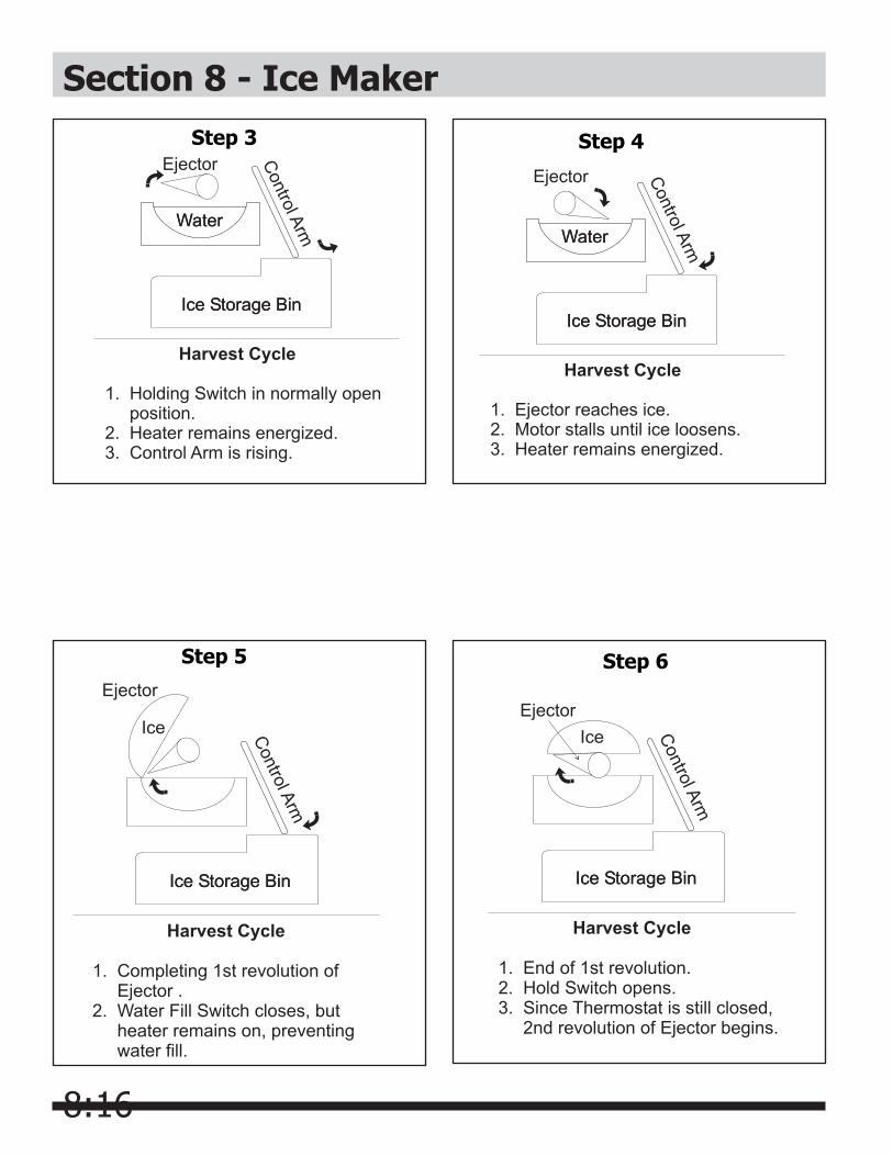
8:16
Section 8 - Ice MakerStep 3 Step 4
Step 5 Step 6

8:17
Section 8 - Ice MakerStep 7 Step 8
Step 9 Step 10

8:18
Section 8 - Ice Maker
S crew S crew
NylonC lamp
C lamp
C lamp
Nylon Nut
S crew
Motor
S crew
S upport
S crew
Ice S tripper
B earing & F ill Trough
Ice MakerC ontrol Arm
S crew
Ice E jector
Ice Maker MoldWith Heater
S crew
LevelingB racket
C am
C lamp
S crew
S crew
S crewS crew
S crew
S crew
I.D. P late
ThermalC utoffAs s embly
S crew
S crew
S crew
S crew Thermos tatAs s embly
S crew
S crew
Hold S witchS P DT
S hut-Off S witchS P DT
Ice MakerArm S pring
Water F illS witchS P DT
Ins ulator
Valve S witchP late
C over
G ear
S crew
MountingP late
S pring
S pacer
Lever ArmS crew
Wiring Harnes sC onnector P lug
WaterInlet Tube
S ingle S olenoidWater ValveAs s embly
INS TALL ATION PAR TS
Water Tube
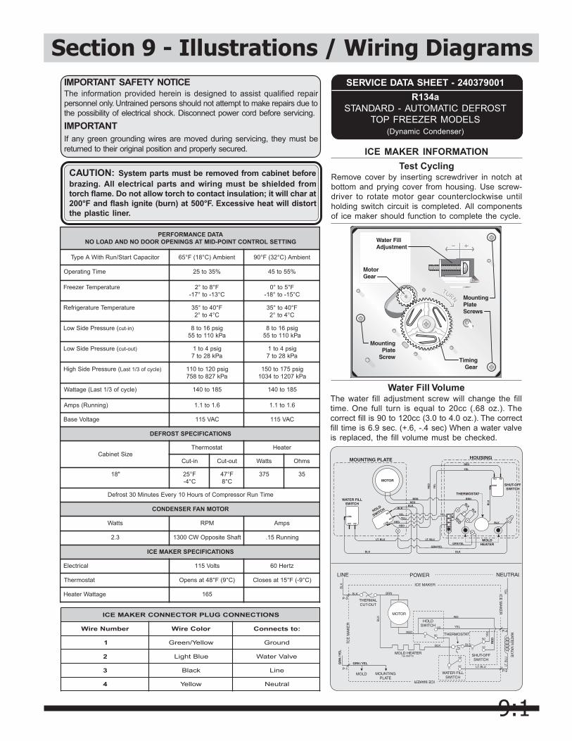
9:1
Section 9 - Illustrations / Wiring Diagrams
ICE MAKER INFORMATIONTest Cycling
Remove cover by inserting screwdriver in notch atbottom and prying cover from housing. Use screw-driver to rotate motor gear counterclockwise untilholding switch circuit is completed. All componentsof ice maker should function to complete the cycle.
ATADECNAMROFREPGNITTESLORTNOCTNIOP-DIMTASGNINEPOROODONDNADAOLON
roticapaCtratS/nuRhtiWAepyT tneibmA)C°81(F°56 tneibmA)C°23(F°09
emiTgnitarepO %53ot52 %55ot54
erutarepmeTrezeerF F°8ot°2C°31-ot°71-
F°5ot°0C°51-ot°81-
erutarepmeTerutaregirfeR F°04ot°53C°4ot°2
F°04ot°53C°4ot°2
(erusserPediSwoL )ni-tuc gisp61ot8aPk011ot55
gisp61ot8aPk011ot55
(erusserPediSwoL )tuo-tuc gisp4ot1aPk82ot7
gisp4ot1aPk82ot7
(erusserPediShgiH )elcycfo3/1tsaL gisp021ot011aPk728ot857
gisp571ot051aPk7021ot4301
)elcycfo3/1tsaL(egattaW 581ot041 581ot041
)gninnuR(spmA 6.1ot1.1 6.1ot1.1
egatloVesaB CAV511 CAV511
SNOITACIFICEPSTSORFED
eziStenibaCtatsomrehT retaeH
ni-tuC tuo-tuC sttaW smhO
"81 F°52C°4-
F°74C°8
573 53
emiTnuRrosserpmoCfosruoH01yrevEsetuniM03tsorfeD
ROTOMNAFRESNEDNOC
sttaW MPR spmA
3.2 tfahSetisoppOWC0031 gninnuR51.
SNOITACIFICEPSREKAMECI
lacirtcelE stloV511 ztreH06
tatsomrehT )C°9(F°84tasnepO )C°9-(F°51tasesolC
egattaWretaeH 561
Water Fill VolumeThe water fill adjustment screw will change the filltime. One full turn is equal to 20cc (.68 oz.). Thecorrect fill is 90 to 120cc (3.0 to 4.0 oz.). The correctfill time is 6.9 sec. (+.6, -.4 sec) When a water valveis replaced, the fill volume must be checked.
SNOITCENNOCGULPROTCENNOCREKAMECI
rebmuNeriW roloCeriW :otstcennoC
1 wolleY/neerG dnuorG
2 eulBthgiL evlaVretaW
3 kcalB eniL
4 wolleY lartueN
SERVICE DATA SHEET - 240379001R134a
STANDARD - AUTOMATIC DEFROSTTOP FREEZER MODELS
(Dynamic Condenser)
CAUTION: System parts must be removed from cabinet beforebrazing. All electrical parts and wiring must be shielded fromtorch flame. Do not allow torch to contact insulation; it will char at200°F and flash ignite (burn) at 500°F. Excessive heat will distortthe plastic liner.
IMPORTANT SAFETY NOTICEThe information provided herein is designed to assist qualified repairpersonnel only. Untrained persons should not attempt to make repairs due tothe possibility of electrical shock. Disconnect power cord before servicing.IMPORTANTIf any green grounding wires are moved during servicing, they must bereturned to their original position and properly secured.

9:2
Section 9 - Illustrations / Wiring Diagrams
63

9:3
Section 9 - Illustrations / Wiring Diagrams
64

9:4
Section 9 - Illustrations / Wiring Diagrams
65
Wiring Diagram
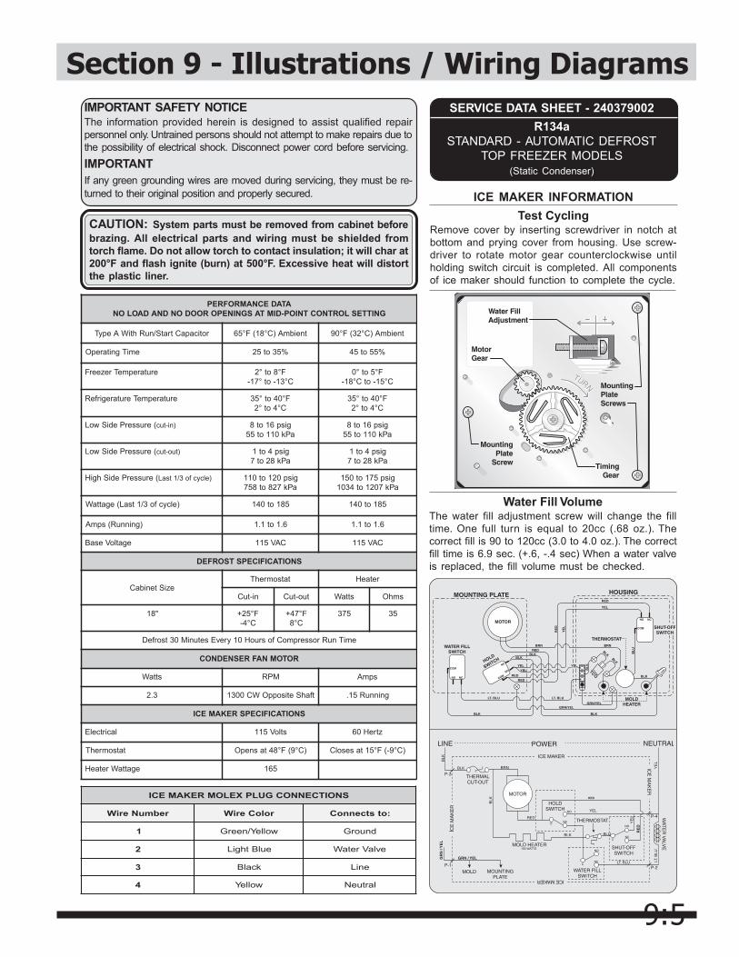
9:5
Section 9 - Illustrations / Wiring Diagrams
ICE MAKER INFORMATIONTest Cycling
Remove cover by inserting screwdriver in notch atbottom and prying cover from housing. Use screw-driver to rotate motor gear counterclockwise untilholding switch circuit is completed. All componentsof ice maker should function to complete the cycle.
ATADECNAMROFREPGNITTESLORTNOCTNIOP-DIMTASGNINEPOROODONDNADAOLON
roticapaCtratS/nuRhtiWAepyT tneibmA)C°81(F°56 tneibmA)C°23(F°09
emiTgnitarepO %53ot52 %55ot54
erutarepmeTrezeerF F°8ot°2C°31-ot°71-
F°5ot°0C°51-otC°81-
erutarepmeTerutaregirfeR F°04ot°53C°4ot°2
F°04ot°53C°4ot°2
(erusserPediSwoL )ni-tuc gisp61ot8aPk011ot55
gisp61ot8aPk011ot55
(erusserPediSwoL )tuo-tuc gisp4ot1aPk82ot7
gisp4ot1aPk82ot7
(erusserPediShgiH )elcycfo3/1tsaL gisp021ot011aPk728ot857
gisp571ot051aPk7021ot4301
)elcycfo3/1tsaL(egattaW 581ot041 581ot041
)gninnuR(spmA 6.1ot1.1 6.1ot1.1
egatloVesaB CAV511 CAV511
SNOITACIFICEPSTSORFED
eziStenibaCtatsomrehT retaeH
ni-tuC tuo-tuC sttaW smhO
"81 F°52+C°4-
F°74+C°8
573 53
emiTnuRrosserpmoCfosruoH01yrevEsetuniM03tsorfeD
ROTOMNAFRESNEDNOC
sttaW MPR spmA
3.2 tfahSetisoppOWC0031 gninnuR51.
SNOITACIFICEPSREKAMECI
lacirtcelE stloV511 ztreH06
tatsomrehT )C°9(F°84tasnepO )C°9-(F°51tasesolC
egattaWretaeH 561
Water Fill VolumeThe water fill adjustment screw will change the filltime. One full turn is equal to 20cc (.68 oz.). Thecorrect fill is 90 to 120cc (3.0 to 4.0 oz.). The correctfill time is 6.9 sec. (+.6, -.4 sec) When a water valveis replaced, the fill volume must be checked.
SNOITCENNOCGULPXELOMREKAMECI
rebmuNeriW roloCeriW :otstcennoC
1 wolleY/neerG dnuorG
2 eulBthgiL evlaVretaW
3 kcalB eniL
4 wolleY lartueN
SERVICE DATA SHEET - 240379002R134a
STANDARD - AUTOMATIC DEFROSTTOP FREEZER MODELS
(Static Condenser)
CAUTION: System parts must be removed from cabinet beforebrazing. All electrical parts and wiring must be shielded fromtorch flame. Do not allow torch to contact insulation; it will char at200°F and flash ignite (burn) at 500°F. Excessive heat will distortthe plastic liner.
IMPORTANT SAFETY NOTICEThe information provided herein is designed to assist qualified repairpersonnel only. Untrained persons should not attempt to make repairs due tothe possibility of electrical shock. Disconnect power cord before servicing.IMPORTANTIf any green grounding wires are moved during servicing, they must be re-turned to their original position and properly secured.
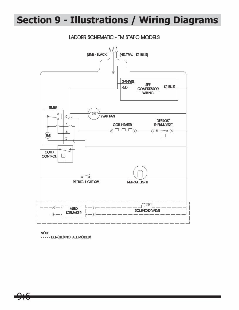
9:6
Section 9 - Illustrations / Wiring Diagrams
67
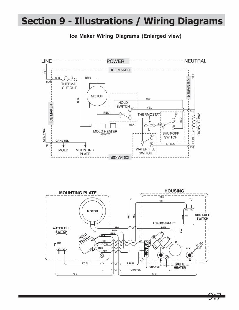
9:7
Section 9 - Illustrations / Wiring Diagrams
68
Ice Maker Wiring Diagrams (Enlarged view)

10:1
Section 10 - Exploded Views
B - 1
System Diagram

10:2
Section 10 - Exploded Views
B - 2
Cabinet Diagram
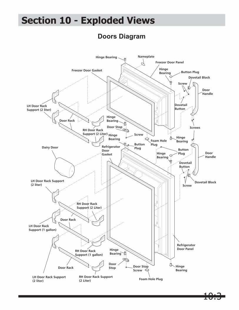
10:3
Section 10 - Exploded Views
B - 3
Doors Diagram
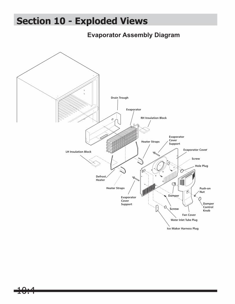
10:4
Section 10 - Exploded Views
B - 4
Evaporator Assembly Diagram


![Capillary thermostatting in capillary electrophoresis · Capillary thermostatting in capillary electrophoresis ... 75 µm BF 3 Injection: ... 25-µm id BF 5 capillary. Voltage [kV]](https://img.pdfslide.net/doc/110x75/5c176ff509d3f27a578bf33a/capillary-thermostatting-in-capillary-electrophoresis-capillary-thermostatting.jpg)