Embed Size (px)
Citation preview
1

2
All-in-one Design
The Studer OnAir 2500 ensures a new standard in ease-of-use for Radio or TV Broadcast, and is available in both a fixed frame model for portability, or the Modulo version for recessed installation in studio furniture.
Designed as an integrated system – on the Fixed Frame model the control surface, I/O breakout, DSP and controller boards, as well as power supply, share the same chassis – it addresses the medium segment of the live broadcast market including both private and public network stations. Its self-contained architecture without an external core reduces wiring complexity and setup time to a minimum. This makes the OnAir 2500 the ideal audio mixing console for OB applications, where robustness and reliability are a must.
The Modulo version simply offers the same functions in separate modules which are easily connected together when installed in tabletop furniture.
Studer’s OnAir 2500 user-interface builds upon the highly acclaimed operational concept of the OnAir 2000 and OnAir 3000.
Having been introduced to the market with the very successful OnAir 2000, Studer’s patented “Touch’n’Action” philosophy is incorporated into the OnAir 2500.
The OnAir 2500 even runs the same mature software platform as the OnAir 3000. Full compatibility with other systems of the OnAir family and a short learning curve for operators with OnAir 3000 experience are only two of many advantages.
OnAir 2500 Modulo.For installation in tabletop furniture
3
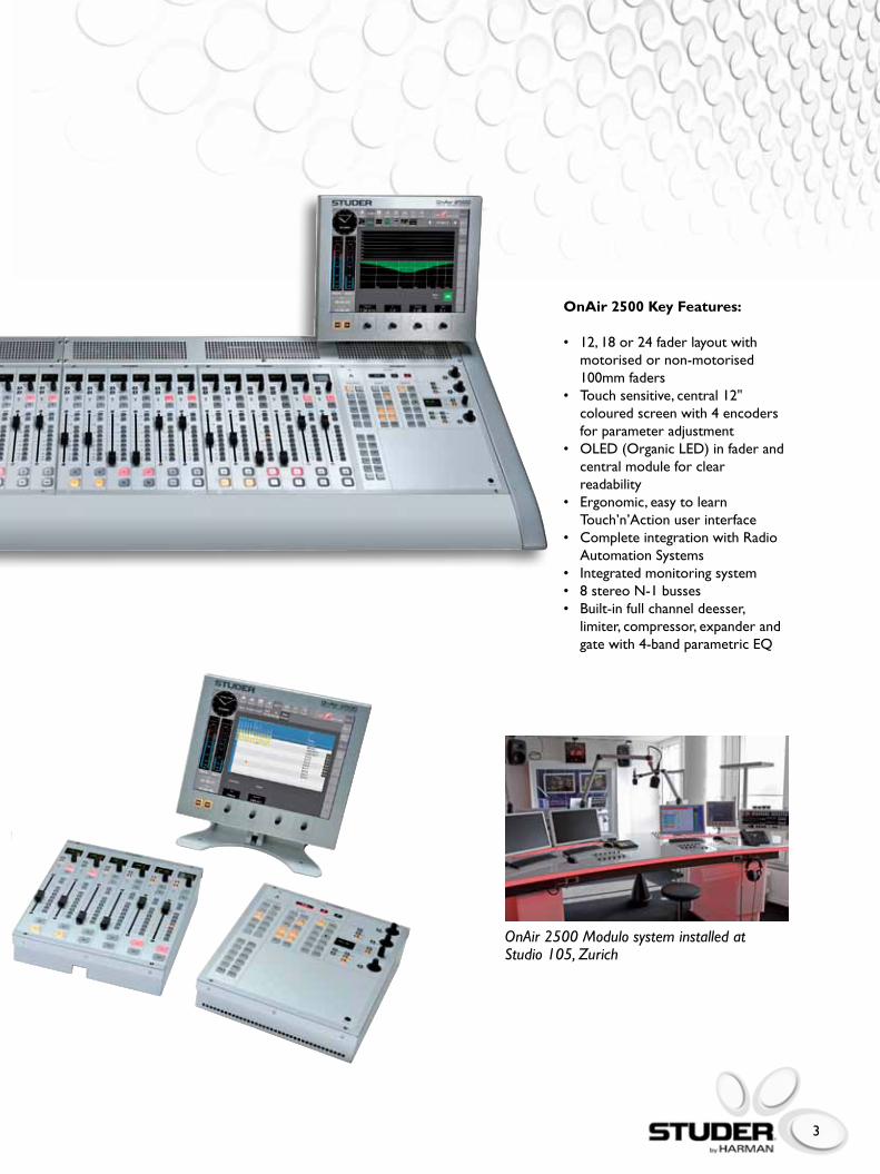
OnAir 2500 Key Features:
• 12,18or24faderlayoutwith motorised or non-motorised 100mm faders• Touchsensitive,central12" colouredscreenwith4encoders for parameter adjustment• OLED(OrganicLED)infaderand central module for clear readability• Ergonomic,easytolearn Touch’n’Action user interface• CompleteintegrationwithRadio Automation Systems• Integratedmonitoringsystem• 8stereoN-1busses• Built-infullchanneldeesser, limiter, compressor, expander and gatewith4-bandparametricEQ
OnAir 2500 Modulo system installed at Studio 105, Zurich

4
Ready For Broadcast – Whenever And Wherever You Want
LikeallotherproductsinStuder’sOnAir portfolio, the OnAir 2500 provides you and your operators with a wide and well-balanced broadcast feature set. Typical functions for your every day work, like muting the monitor speaker signal while microphones are open, are already integrated and need not be configured, saving time and money. Nonetheless,nearlyallfunctionscanbe easily activated, deactivated or customised using the configuration user interface on the main screen.
The ergonomic design and the simple usability of the OnAir 2500 means that it’s ideally suited to stressful live on-air operation. Being under continuous time pressure, the DJ can change from live presentation to off air recording, from pre-conferencing to OB connections. This is where simple and intiutive operation have highest priority. The OnAir 2500 is entirely geared to let your talents do their job: making radio.
The OnAir 2500 supports your daily work even more. In most installations, the console will be operated in a multiuser environment Therefore, you can create user accounts defined with individual access restrictions on specified console functions. This applies as well for the system snapshots, which are stored internally and contain custom sets of signal parameters, crosspoint settings and channel assignment. According to the
configured rights, users may have access to only a limited number of snapshots. Independently, it is possible to store snapshots externally on a USB memory stick, connected to a socket on the main screen.
With the OnAir 2500, Studer has defined a new standard in ease-of useforradiobroadcast.Likenoother console, the OnAir 2500 with its compact architecture is the ideal solution for your mobile applications, especially because it does not need anyexternalDSPcore.Everysignalyou need is connected directly to the rearpanel.Nowastedtimesettingup links to cores and networks, the intuitive architecture ensures you’re on-air fast!
5
Studer’s OnAir 2500 is designed as an integrated system – control surface, I/O breakout, DSP and controller boards, as well as power supply, share the same chassis. Modules of 6 faders build the basis for the three availableconsolessizeswith12,18or24faders.Acentralmoduleineveryconsole layout provides the operators with a monitoring section, on air indication, a talkback section and a built-in talkback microphone.
Despite its compactness, the OnAir 2500 can be easily extended. When installed in a control room and connected to a voice booth, a talkback and monitoring module (A943.044400orA943.044700)canbe attached to enable communication between engineer and journalist, or even from the voice booth to anyotherdestination,e.g.theN-Xreturns. Additonally, this extension includes an independent studio monitoring module with separate volume control for studio speakersand headphones.
The talkback and monitoring module is connected directly to the OnAir 2500 viaADAT(audio)andCAT5(control).The respective interfaces on the rear panel are already preconfigured for this purpose.
To allow fail-safe operation in case of mains power loss, Studer offers an external power supply for the OnAir2500,inasmart1RU19”chassis. This used as secondary feed providing24VDCtotheconsole.
This all-in-one design is characterised by a very small footprint. The smallest version of the OnAir 2500 with 12 fadersrequiresonly80x50cmandthetotalweightof17kgsfurtherreinforces the mobile capability.Pushbuttons throughout the entire console are made of silent rubber pads, guaranteeing noiseless
operation and perfect tactile feedback.
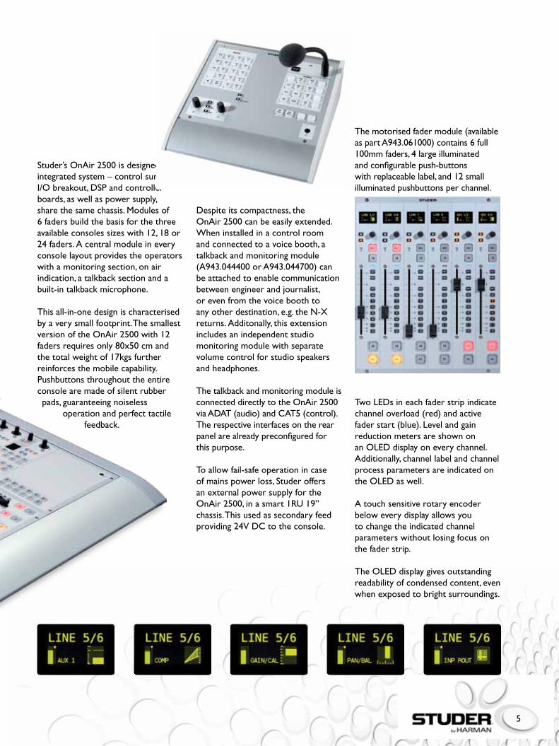
Themotorisedfadermodule(availableaspartA943.061000)contains6full100mmfaders,4largeilluminatedand configurable push-buttons with replaceable label, and 12 small illuminated pushbuttons per channel.
TwoLEDsineachfaderstripindicatechanneloverload(red)andactivefaderstart(blue).Levelandgainreduction meters are shown on anOLEDdisplayoneverychannel.Additionally, channel label and channel process parameters are indicated on theOLEDaswell.
A touch sensitive rotary encoder below every display allows you to change the indicated channel parameters without losing focus on the fader strip.
TheOLEDdisplaygivesoutstandingreadability of condensed content, even when exposed to bright surroundings.
6
QuickAndIntuitiveOperation
LiketheOnAir3000,theoperationof the desk is based on Studer’s well proven and worldwide accepted “Touch’n’Action” user interface concept. Within minutes, your talent is able to operate the console. If your staff is already experienced with the OnAir 3000, getting familiar with the OnAir 2500 is simple. This is ensured by the clear layout of the user interface.
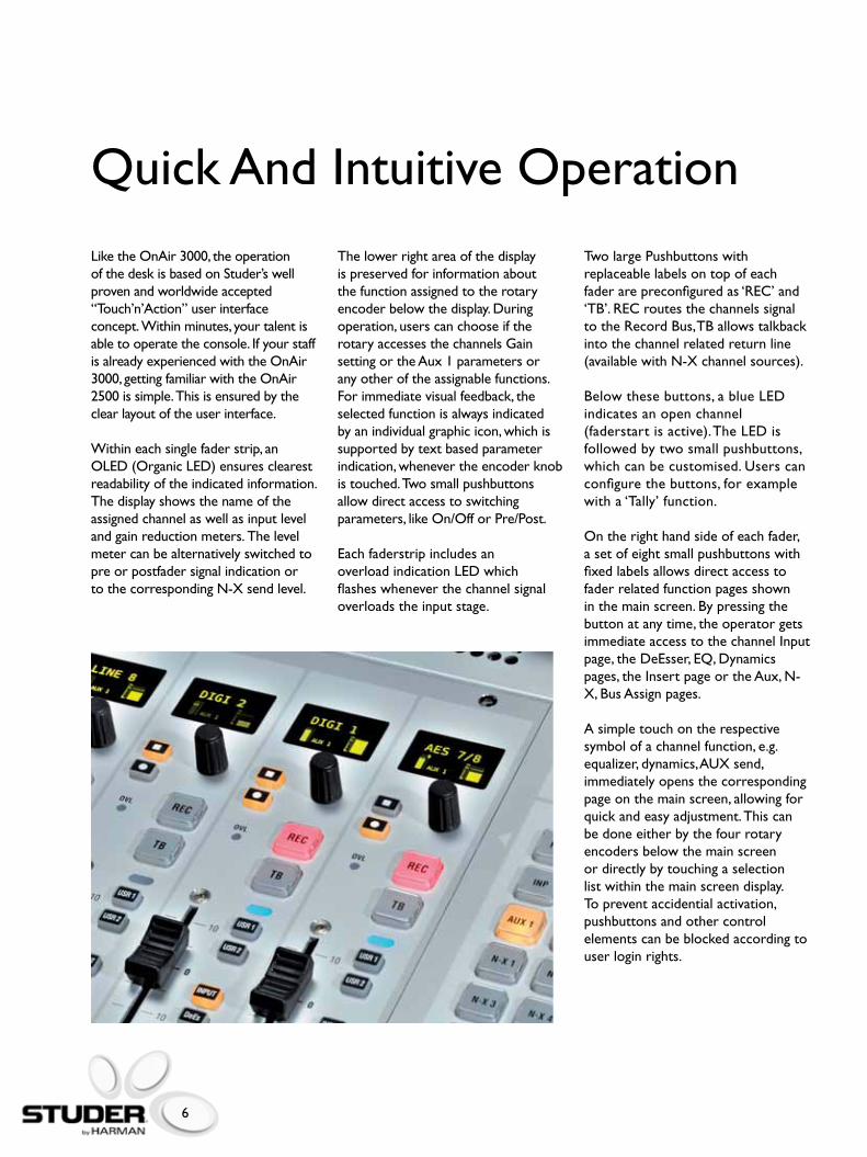
Within each single fader strip, an OLED(OrganicLED)ensuresclearestreadability of the indicated information. The display shows the name of the assigned channel as well as input level and gain reduction meters. The level meter can be alternatively switched to pre or postfader signal indication or tothecorrespondingN-Xsendlevel.
The lower right area of the display is preserved for information about the function assigned to the rotary encoder below the display. During operation, users can choose if the rotary accesses the channels Gain setting or the Aux 1 parameters or any other of the assignable functions. For immediate visual feedback, the selected function is always indicated by an individual graphic icon, which is supported by text based parameter indication, whenever the encoder knob is touched. Two small pushbuttons allow direct access to switching parameters, like On/Off or Pre/Post.
EachfaderstripincludesanoverloadindicationLEDwhichflashes whenever the channel signal overloads the input stage.
Two large Pushbuttons with replaceable labels on top of each faderarepreconfiguredas‘REC’and‘TB’.RECroutesthechannelssignalto the Record Bus, TB allows talkback into the channel related return line (availablewithN-Xchannelsources).
Belowthesebuttons,ablueLEDindicates an open channel (faderstartisactive).TheLEDisfollowed by two small pushbuttons, which can be customised. Users can configure the buttons, for example with a ‘Tally’ function.
On the right hand side of each fader, a set of eight small pushbuttons with fixed labels allows direct access to fader related function pages shown in the main screen. By pressing the button at any time, the operator gets immediate access to the channel Input page,theDeEsser,EQ,Dynamicspages,theInsertpageortheAux,N-X,BusAssignpages.
A simple touch on the respective symbol of a channel function, e.g. equalizer,dynamics,AUXsend,immediately opens the corresponding page on the main screen, allowing for quick and easy adjustment. This can be done either by the four rotary encoders below the main screen or directly by touching a selection list within the main screen display. To prevent accidential activation, pushbuttons and other control elements can be blocked according to user login rights.
7
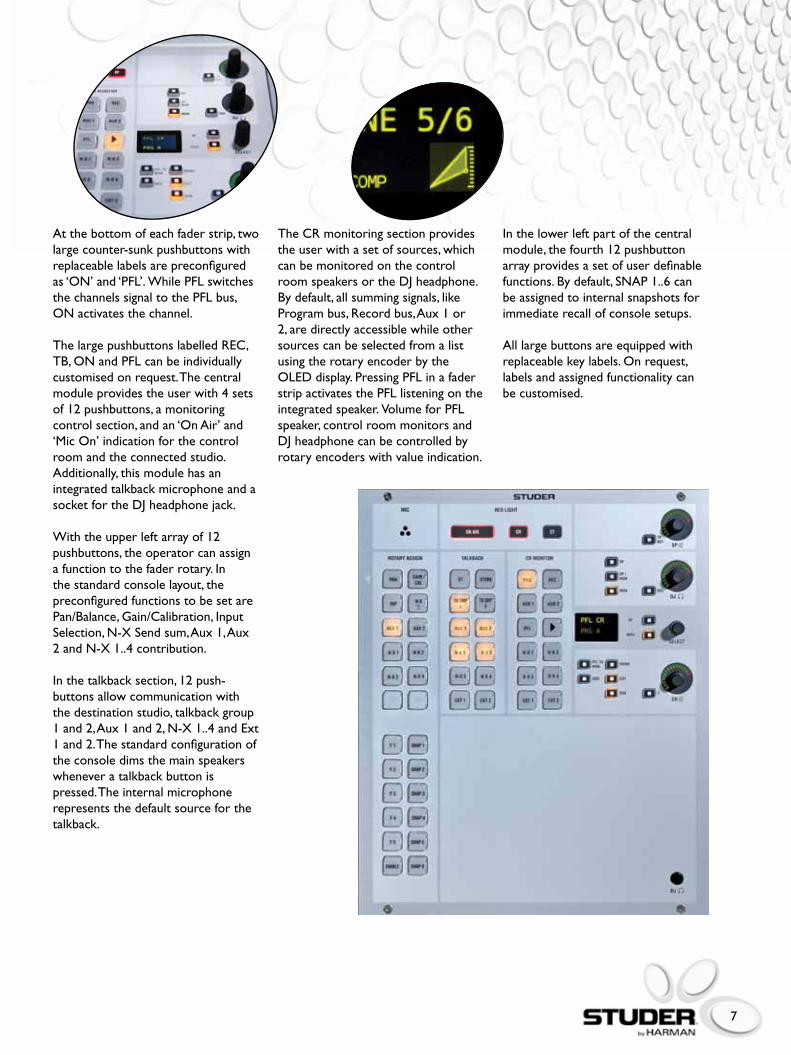
TheCRmonitoringsectionprovidesthe user with a set of sources, which can be monitored on the control room speakers or the DJ headphone. By default, all summing signals, like Program bus, Record bus, Aux 1 or 2, are directly accessible while other sources can be selected from a list using the rotary encoder by the OLEDdisplay.PressingPFLinafaderstripactivatesthePFLlisteningontheintegratedspeaker.VolumeforPFLspeaker, control room monitors and DJ headphone can be controlled by rotary encoders with value indication.
At the bottom of each fader strip, two large counter-sunk pushbuttons with replaceable labels are preconfigured as‘ON’and‘PFL’.WhilePFLswitchesthechannelssignaltothePFLbus,ONactivatesthechannel.
ThelargepushbuttonslabelledREC,TB,ONandPFLcanbeindividuallycustomised on request. The central moduleprovidestheuserwith4setsof 12 pushbuttons, a monitoring control section, and an ‘On Air’ and ‘Mic On’ indication for the control room and the connected studio. Additionally, this module has an integrated talkback microphone and a socket for the DJ headphone jack.
With the upper left array of 12 pushbuttons, the operator can assign a function to the fader rotary. In the standard console layout, the preconfigured functions to be set are Pan/Balance,Gain/Calibration,InputSelection,N-XSendsum,Aux1,Aux2andN-X1..4contribution.
In the talkback section, 12 push-buttons allow communication with the destination studio, talkback group 1and2,Aux1and2,N-X1..4andExt1 and 2. The standard configuration of the console dims the main speakers whenever a talkback button is pressed. The internal microphone represents the default source for the talkback.
In the lower left part of the central module, the fourth 12 pushbutton array provides a set of user definable functions.Bydefault,SNAP1..6canbe assigned to internal snapshots for immediate recall of console setups.
All large buttons are equipped with replaceable key labels. On request, labels and assigned functionality can be customised.
8
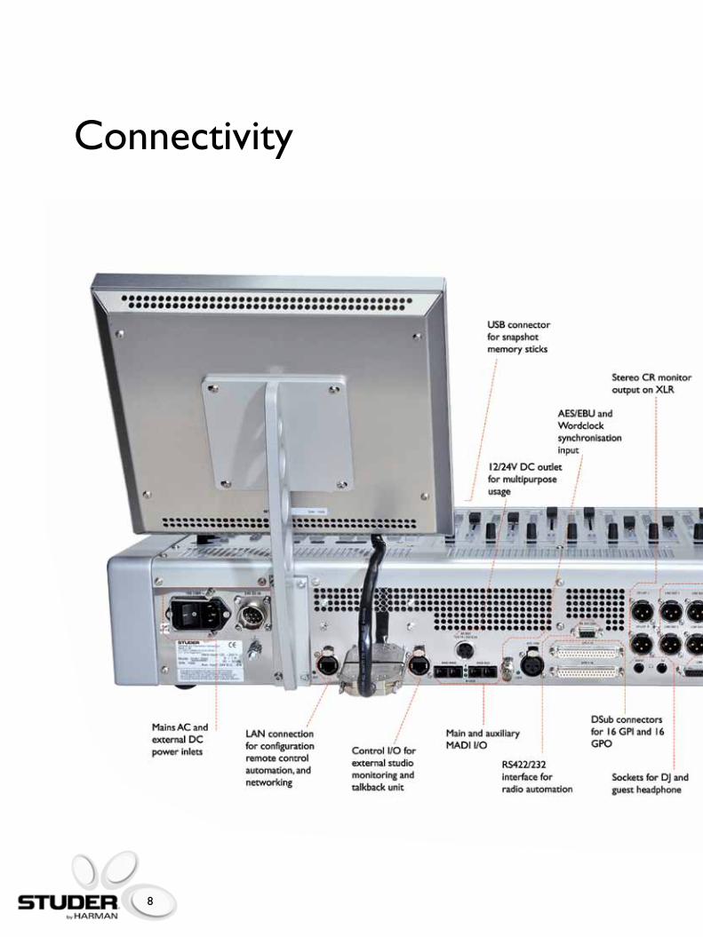
Connectivity

9
Input and output modules The following D21m input and output cardsare available:
•Microphone / line card, 4 Channels With analogue insert extension connector•Analogue Insert card Provides4balancedinsertsendand return paths•Line In card, 8 channels 24bitDelta-SigmaA/Dconvertercard•Line Out card, 8 channels 24 bit Delta- Sigma D/A converter card•AES/EBU card, 8 channels AES/ EBU in, 8 channels AES/EBU out Availableeitherwithi/pSRC,withi/p ando/pSRC,orwithoutSRC•ADAT card, 2 x 8 channels i/p and 2 x 8 channel o/p With optical interfaces•TDIF card Provides 2 TDIF interfaces•MADI card Providesoptical64chMADIinterface•GPIO card 16 opto-coupler general purpose inputs 16 open collector general purpose outputs, also available with relays. •HD Mic card Transformer-based mic input card
The D21m system automatically detects newly inserted cards in real time and sends the appropriate information to the main controller in the OnAir 2500. Additionally, in the case of a card failure an error message is transmitted and displayed on the GUI.
The OnAir 2500 provides you with an attractive set of local inputs and outputs in multiple formats. By connecting a Studer D21m I/O Breakout box via MADI, the number and format of the available I/Os can be extended.

10
StuderRELINKI/Osharing
One of the benefits of the Studer RELINKsystemincomparisontoothers is that it is based totally on Studer’sexistingSCoreplatformwhich is an integral part of a Studer console architecture, so no additional hardware or breakout boxes are required to complete the network. CommunicatingoverTCP/IPwitheach other, any combination of Studer Vista(5,6,7,8),theOnAir2500and3000 consoles, as well as Route 6000 canlinkviaRELINK.
RELINKisseamless,scaleable,flexible,and can start with a simple link between two Studer consoles, right through to multi-console systems using a two-step topology where all signals are matrixed through a central device, e.g. the Studer Route 6000 system.
Source selection is transparent, and signal labels are automatically transferred to the consuming locations, so the operator always knows what source is connected. Signal takeover between studios is seamless,soRELINKiswell-suitedfor live transmission switchover. A resilient mic take-over mechanism ensures that mic control parameters such as analogue gain, phantom voltage, etc. are not unintentionaly changed but require concious take-overconfirmation.Localmonitoring at point of use is turned off automatically to prevent feedback, indicated with red light signalling, automatically following the source, wherever it is used.
A very common application in radio houses is a voice or news booth connected closely to a studio for speech contribution to a broadcast or a recording, while a second studio is used for production. The booth resources(microphone,headphonesandindication)arephysicallyconnected to one console, usuallyto the one used most in combination withthebooth(theoneinStudio1inourexample).Thisconsoleprovides the monitoring signal for the headphones, controls the microphone parameters as well as the ready/on air indicators. If the second studio (Studio2)requirestheboothforproduction, I/O Sharingallows forwarding the control of the microphone parameters and the indication from the console in Studio 1 to the one in Studio 2. Via a physical connection(tieline)betweenbothstudios, the audio signal is provided to Studio 2.
TheOnAir2500canbeintegratedeasilywithintheStuderRELINKResourceLinkingmanagedI/Osharing system, which can link numerous Studer consoles in various locations of a Broadcast facility to allow audio source and control data sharing across a wide network.
This audio interconnection can be of anytype,forexampleAES3.
The monitoring signal for the headphones is still provided by the console in Studio 1, but the monitoring signal is delivered by the console in Studio 2 via a suitable tie line(e.g.AES3)androutedtotheheadphones remotely. While Studio 2 works with the booth, it controls the microphone parameters, including analog gain and phantom power. Opening the microphone in Studio 2 activates the red light in the booth, presuming that the ‘mic on’ parameters are configured accordingly. In this case, existing monitor speakers will be cut remotely as well. Sharing the control information is established viaanetworkconnection(Ethernet)between all systems involved.
11
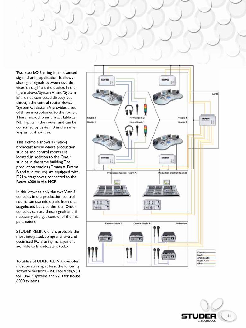
Two-step I/O Sharing is an advanced signal sharing application. It allows sharing of signals between two de-vices ‘through’ a third device. In the figure above, ‘System A’ and ‘System B’ are not connected directly but through the central router device ‘SystemC’.SystemAprovidesasetof three microphones to the router. These microphones are available as NETInputsintherouterandcanbeconsumed by System B in the same way as local sources.
Thisexampleshowsa(radio-)broadcast house where production studios and control rooms are located, in addition to the OnAir studios in the same building. The productionstudios(DramaA,DramaBandAuditorium)areequippedwithD21m stageboxes connected to the Route6000intheMCR.
In this way, not only the two Vista 5 consoles in the production control rooms can use mic signals from the stageboxes, but also the four OnAir consoles can use these signals and, if necessary, also get control of the mic parameters.
STUDERRELINKoffersprobablythemost integrated, comprehensive and optimised I/O sharing management available to Broadcasters today.
ToutiliseSTUDERRELINK,consolesmust be running at least the following softwareversions–V4.1forVista,V3.1for OnAir systems and V2.0 for Route 6000 systems.
12
SystemSurveillanceviaSNMP
The system state of an OnAir console can be optionally monitored viaSNMPmessaging.TheSimpleNetworkManagementProtocolis a common method to monitor and control networked devices independent of type and usage.
ThewaySNMPisimplementedenablestwo different methods of receiving information from a single or multiple OnAir systems in an IP network. Systems can actively send important status information to the connected network.Specialmessages(Traps)aretriggered when parameters reach or surpass predefined thresholds, e.g. a processor’s temperature has risen to a critical level, or a console’s ‘On Air’ state is activated. Additionally, traps are sent on any occurring system alert, e.g. PSU error or synchronisation switch-over. Such active sending does not need any user interaction.
For surveillance issues, users can also request the current status information of system parameters (Polls).Thisispossibleatanytimeand independent from status and parameter. Thresholds for traps can be configured in a corresponding XMLfileforeachconsole.
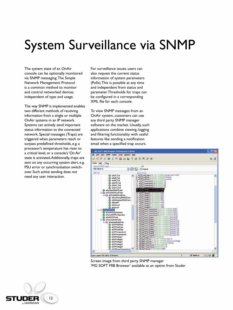
ToviewSNMPmessagesfromanOnAir system, customers can use anythirdpartySNMPmanagersoftware on the market. Usually, such applications combine viewing, logging and filtering functionality with useful features like sending a notification email when a specified trap occurs.
ScreenimagefromthirdpartySNMPmanager‘MG SOFT MIB Browser’ available as an option from Studer

13
Radio Integration
With the OnAir 2500, networking and integration is easy.
Optional support of I/O Sharing allows Studer’s sophisticated technology to share signals with other Studer devices regardless of model. In a networked installation with multiple OnAir 2500 and OnAir 3000, Route 6000 and Vista systems, operators can use I/Os from these systems and have full access to all parameters of shared I/Os.
The OnAir 2500 allows integration with radio automation systems. Remote control in both directions from the console to the automation system and vice versa, is possible via Monitora option. A single playout session can be established via serial interface, while multiple sessions are possibleviaTCP/IP.Incombinationwith the audio connection over IEEE1394Firewirewith8chI/Othismeans an effective reduction of wiring complexity and allows the user to be on-air ready, fast.
Router control via ProBel is optionally available. The console is able to send crosspoint commands to a Router using the comfortable main screen as a controller, but it is also possible to activate output patches in the router. Patches are sets of predefined crosspoints, which can be activated by pressing a single button on the console surface.
The OnAir 2500 can also be integratedwithStuder’sCallManagementSystem,CMS.Thissystem replaces the usual telephone in a studio by software clients, allowing sophisticated management of incoming calls in a networked environment.
TheCMSisabletoautomaticallyroute incoming callers to pre-configured fader channels, allowing caller names to be shown dynamically as fader channel labels.Finally,theoptionalSNMPfunctionality enables the system to send information into the network to monitor the system’s health. Nearlyanyparametercanbeselected for surveillance.
14
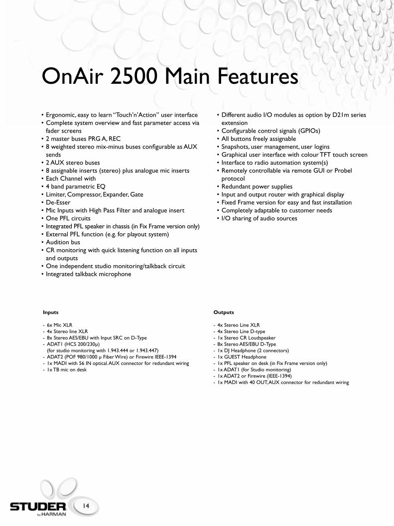
•Ergonomic,easytolearn“Touch’n’Action”userinterface•Completesystemoverviewandfastparameteraccessvia fader screens•2masterbusesPRGA,REC•8weightedstereomix-minusbusesconfigurableasAUX sends•2AUXstereobuses•8assignableinserts(stereo)plusanaloguemicinserts•EachChannelwith•4bandparametricEQ•Limiter,Compressor,Expander,Gate•De-Esser•MicInputswithHighPassFilterandanalogueinsert•OnePFLcircuits•IntegratedPFLspeakerinchassis(inFixFrameversiononly)•ExternalPFLfunction(e.g.forplayoutsystem)•Auditionbus•CRmonitoringwithquicklisteningfunctiononallinputs and outputs•Oneindependentstudiomonitoring/talkbackcircuit•Integratedtalkbackmicrophone
•DifferentaudioI/OmodulesasoptionbyD21mseries extension•Configurablecontrolsignals(GPIOs)•Allbuttonsfreelyassignable•Snapshots,usermanagement,userlogins•GraphicaluserinterfacewithcolourTFTtouchscreen•Interfacetoradioautomationsystem(s)•RemotelycontrollableviaremoteGUIorProbel protocol•Redundantpowersupplies•Inputandoutputrouterwithgraphicaldisplay•FixedFrameversionforeasyandfastinstallation•Completelyadaptabletocustomerneeds•I/Osharingofaudiosources
Inputs
- 6xMicXLR- 4xStereolineXLR- 8xStereoAES/EBUwithInputSRConD-Type-ADAT1(HCS200/230μ) (forstudiomonitoringwith1.943.444or1.943.447)-ADAT2(POF980/1000μFiberWire)orFirewireIEEE-1394- 1xMADIwith56INoptical.AUXconnectorforredundantwiring- 1x TB mic on desk
Outputs
-4xStereoLineXLR- 4xStereoLineD-type- 1xStereoCRLoudspeaker- 8xStereoAES/EBUD-Type- 1xDJHeadphone(2connectors)- 1xGUESTHeadphone- 1xPFLspeakerondesk(inFixFrameversiononly)- 1xADAT1(forStudiomonitoring)- 1xADAT2orFirewire(IEEE-1394)- 1xMADIwith40OUT,AUXconnectorforredundantwiring
OnAir 2500 Main Features
15
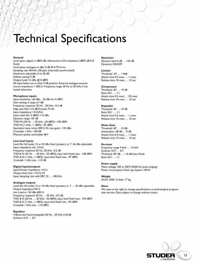
Technical SpecificationsGeneralLevelspecs,digital,indBFS:dB,referencedtofullmodulation(dBFS,dBFullScale)Levelspecs,analogue,indBu:0dBØ0.775VrmsSamplingrate:48kHz±50ppm(internallysynchronized)Headroom adjustable: 0 to 20 dBDefaultsetting:9dBOutputLevel:15dBu@0dBFSAllinputfaderssettotheir0dBposition.Externalanaloguesources:source impedance < 200 Ω. Frequency range: 20 Hz to 20 kHz, if not stated otherwise.
Microphone inputsInput sensitivity: –60 dBu…26 dBu for 0 dBFSGain setting: in steps of 1dBFrequency response: 30 Hz…20 kHz, –0.3 dBHighpassfilter(12dB/Octave):75HzInputimpedance:1.8kOhmInsertlevel(for0dBFS)+15dBuDynamicrange:107dBTHD+N(30Hz…20kHz,–30dBFS):–100dBFSTHD+N(1kHz,–1dBFS):–95dBFSEquivalentinputnoise(200ΩRi,maxgain):–124dBuCrosstalk,1kHz:–100dBPhantompower,switchable:48V
Line level inputsLevel(forfullscale)15or24dBufixed(jumper),or7...26dBuadjustableInput impedance min. 10 kΩFrequency response 20 Hz...20 kHz –0.2 dBTHD&N(35Hz…20kHz,–30dBFS),inputlevelfixedmax.–108dBFSTHD&N(1kHz,–1dBFS),inputlevelfixedmax.–97dBFSCrosstalk1kHzmax.–110dB
Digital inputs/outputsInput/Output impedance 110 ΩOutputlevel(into110Ω)5VInputSamplingratewithSRC32…108kHz
Analogue outputsLevel(forfullscale)15or24dBufixed(jumper),or7…26dBuadjustableOutput Impedance 50 Ωmin.Loadat+24dBu600ΩFrequency response 20 Hz … 20 kHz –0.2 dBTHD&N(20Hz…20kHz,–30dBFS),inputlevelfixedmax.–104dBFSTHD&N(1kHz,–1dBFS),inputlevelfixedmax.–93dBFSCrosstalk1kHzmax.–110dBFS
Equalizer4Band,eachbandsweepable20Hz…20kHz:±18dBQ-factor0.27…8.7
DynamicsDynamiclevel0dB…+24dBDynamicsON/OFF
LimiterThreshold-39…+9dBAttack time 0.2 msec … 1 msecRelease time 10 msec … 10 sec
CompressorThreshold-87…+9dBRatio 20:1 … 1:1Attack time 0.2 msec … 20 msecRelease time 10 msec … 10 sec
ExpanderThreshold-87…+9dBRatio 20:1 … 1:1Attack time 0.2 msec … 1 msecRelease time 10 msec … 10 sec
Noise GateThreshold-87…+9dBAttenuation-48dB…0dBAttack time 0.2 msec … 1 msecRelease time 10 msec … 10 sec
De-esserFrequencyrange4kHz…14kHzQ-factor0.27…8.7Threshold-87dB…+8dBAutoModeRatio 20:1 … 1:1
Power supplyMainsvoltage:100to240V,50/60Hz(auto-ranging)Power consumption Desk: typ. System 100 W
WeightOnAir250012fader17kg
Note:We reserve the right to change specifications as technological progress may warrant. Data subject to change without notice

16
292.2 mm
812 mm (12 Fader)
1056 mm (18 Fader)
1300 mm (24 Fader)
732 mm (12 Fader)
122 mm
40 mm
8 mm
OnAir 2500 Fixed Frame
39 mm
392
mm
129.
4 m
m
260.2 mm
17.4
mm
379 mm
465 mm
524 mm
10o

17
Service and Support
Studer has produced and delivered far more than a thousand time-tested and proven digital OnAir mixing consoles throughout the world, many of which are inuse24hoursaday,sevendaysaweek.Duetothemodulardesignandtheself-configuring software, individual hardware items can be easily and quickly exchanged at the customer’s site. We at Studer know that reliability is vital to our customers. Therefore Studer offers world wide service and support for its products. Studer also offers operator training and service on-site or in the factory.intheUKPleaseconsultyourlocalStuderrepresentative.
Please note that the maximum distance between the CORE FRAME and MAIN SCREEN and CENTRAL MODULE is 2m
23 mm
207 mm
243.6 mm243.6 mm
292 mm
Cutout: 244.6 mm Cutout: 244.6 mm
300
mm
Cut
out:
301
mm
260
mm
300
mm
Cut
out:
301
mm
269 mm64 mm64 mm
221.
5 m
m
482.6 mm 380 mm
275
mm
284
mm
Central Module Fader Module Screen Module
Core Rack (Front View)
(Rear View)
OnAir 2500 Modulo
18
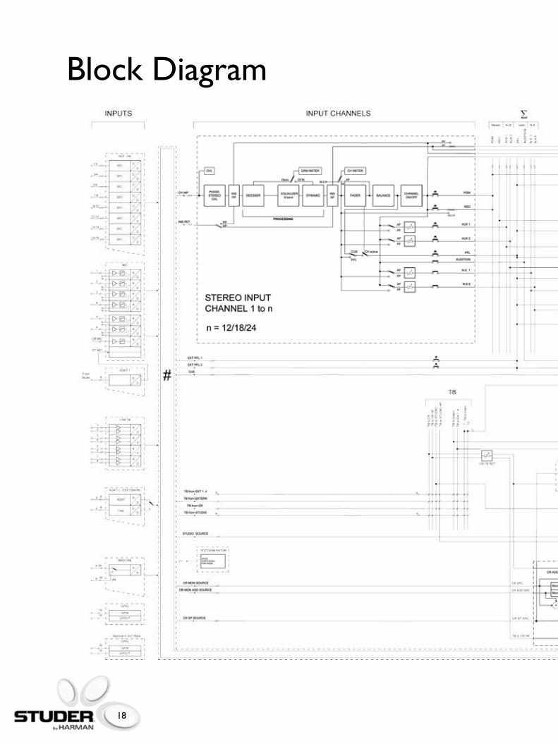
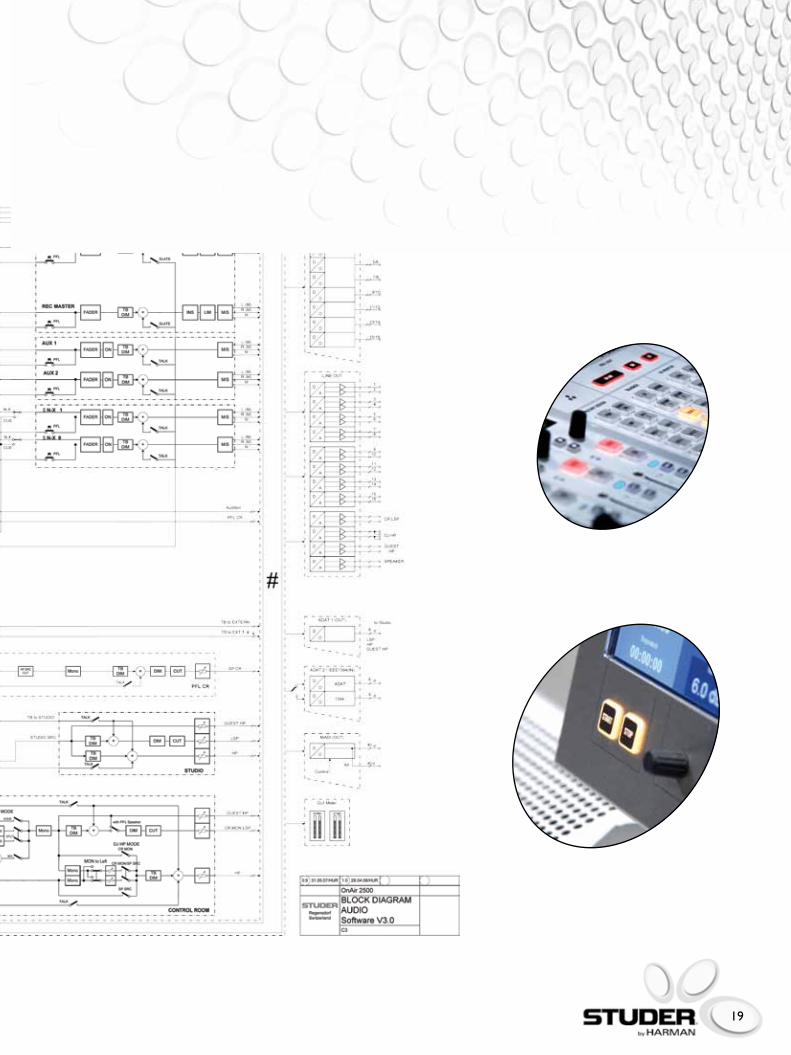
Block Diagram
19

20
Studer Professional Audio GmbH Riedthofstrasse 214, CH-8105 Regensdorf-Zurich Switzerland, Phone +41 44 870 75 11, Fax +41 44 870 71 34
Studer USA, 8500 Balboa Boulevard, Northridge, CA 91329, Phone +1-818-920-3212, Fax +1-818-920-3208
BD10.265970Ed0311
Studer reserves the right to improve or otherwise alter any information supplied in this document or any other documentation supplied hereafter. E&OE 03/11
®
www.studer.ch