Embed Size (px)
Citation preview

CSA 140ZCSA 180Z
CSA 1120ZCSA 240ZCSA 280Z
CSA 2120Z
Commercial Series Amplifier
Operation Manual
JBL Commercial Series
2
This manual does not include all of the details of design, production, or variation of the equipment. Nor does it cover every pos-sible situation which may arise during installation, operation or maintenance.
The information provided in this manual was deemed accurate as of the publication date. However, updates to this information may have occurred.
Trademark Notice: JBL is registered trademark of JBL International. CROWN and DRIVECORE are registered trademarks of Crown Audio. Other trademarks are the property of their respective owners.
© 2014 JBL Commercial, 8760 South Sandy Parkway, Sandy, UT. All Rights Reserved.
ContentsImportant Safety Instructions .......................................................................... 3JBL DECLARATION OF CONFORMITY .......................................................... 51.0 Welcome ................................................................................................... 7 1.1 Features ................................................................................................. 7 1.2 Front Control Panels and Indicators ...................................................... 8 1.3 Rear Panel Controls and Connectors..................................................... 92.0 Setup ........................................................................................................10 2.1 Unpacking Your Amplifier ......................................................................10 2.2 Installing Your Amplifier .........................................................................10 2.3 Ensuring Proper Cooling .......................................................................14 2.4 Choosing Input Wire and Connectors ...................................................14 2.5 Output Wiring and Connectors .............................................................15 2.6 Wiring Your Audio System .....................................................................16 2.7 Connecting to AC Mains .....................................................................17 2.8 Protecting Your Speakers .....................................................................17 2.9 Startup Procedure .................................................................................173.0 Operation ..................................................................................................18 3.1 Precautions .............................................................................................18
3.2 High-Z Switch .........................................................................................19 3.3 Remote Volume Control ..........................................................................19 3.4 Sleep Mode ............................................................................................194.0 Troubleshooting ........................................................................................20 Appendix A: Target Performance Specifications ............................................21
Appendix B: Contact Information ....................................................................22
3
IMPORTANT SAFETY INFORMATION
WARNING FOR YOUR PROTECTIONREAD THE FOLLOWING:
KEEP THESE INSTRUCTIONS
HEED ALL WARNINGS
FOLLOW ALL INSTRUCTIONS
THE APPARATUS SHALL NOT BE EXPOSED TO DRIPPING OR SPLASHING LIQUID AND NO OBJECT FILLED WITH LIQUID, SUCH AS VASES, SHALL BE PLACED ON THE APPARATUS
CLEAN ONLY WITH A DRY CLOTH.
DO NOT BLOCK ANY OF THE VENTILATION OPENINGS. INSTALL IN ACCORDANCE WITH THE MANUFACTURER’S INSTRUCTIONS.
DO NOT INSTALL NEAR ANY HEAT SOURCES SUCH AS RADIATORS, HEAT REGISTERS, STOVES, OR OTHER APPARATUS (INCLUDING AMPLIFIERS) THAT PRODUCE HEAT.
ONLY USE ATTACHMENTS/ACCESSORIES SPECIFIED BY THE MANUFACTURER.
UNPLUG THIS APPARATUS DURING LIGHTNING STORMS OR WHEN UNUSED FOR LONG PERIODS OF TIME.
Do not defeat the safety purpose of the polarized or grounding-type plug. A polarized plug has two blades with one wider than the other. A grounding type plug has two blades and a third grounding prong. The wide blade or third prong are provided for your safety. If the provided plug does not fit your outlet, consult an electrician for replacement of the obsolete outlet.
Protect the power cord from being walked on or pinched particularly at plugs, convenience receptacles, and the point where they exit from the apparatus.
Use only with the cart stand, tripod bracket, or table specified by the manufacture, or sold with the apparatus. When a cart is used, use caution when moving the cart/apparatus combination to avoid injury from tip-over. Refer all servicing to qualified service personnel. Servicing is required when the apparatus has been damaged in any way, such as power-supply cord or plug is damaged, liquid has been spilled or objects have fallen into the apparatus, the apparatus has been exposed to rain or moisture, does not operate normally, or has been dropped.
POWER ON/OFF SWITCH: For products provided with a power switch, the power switch DOES NOT break the connection from the mains.
MAINS DISCONNECT: The plug shall remain readily operable. For rack-mount or installation where plug is not accessible, an all-pole mains switch with a contact separation of at least 3 mm in each pole shall be incorporated into the electrical installation of the rack or building.
FOR UNITS EQUIPPED WITH EXTERNALLY ACCESSIBLE FUSE RECEPTACLE: Replace fuse with same type and rating only.
MULTIPLE-INPUT VOLTAGE: This equipment may require the use of a different line cord, attachment plug, or both, depending on the available power source at installation. Connect this equipment only to the power source indicated on the equipment rear panel. To reduce the risk of fire or electric shock, refer servicing to qualified service personnel or equivalent.
If connected to 240V supply, a suitable CSA/UL certified power cord shall be used for this supply.
SAFETY INSTRUCTIONS
NOTICE FOR CUSTOMERS IF YOUR UNIT IS EQUIPPED WITH A POWER CORD.
WARNING: THIS APPLIANCE SHALL BE CONNECTED TO A MAINS SOCKET OUTLET WITH A PROTECTIVE EARTHING CONNECTION.
The cores in the mains lead are colored in accordance with the following code:
GREEN and YELLOW - Earth BLUE - Neutral BROWN - Live
As colours of the cores in the mains lead of this appliance may not cor-respond with the colored markings identifying the terminals in your plug, proceed as follows:
• The core which is colored green and yellow must be connected to the terminal in the plug marked with the letter E, or with the earth symbol, or colored green, or green and yellow.
• The core which is colored blue must be connected to the terminal marked N or colored black.
• The core which is colored brown must be connected to the terminal marked L or colored red.
This equipment may require the use of a different line cord, attachment plug, or both, depending on the available power source at installation. If the attachment plug needs to be changed, refer servicing to qualified ser-vice personnel who should refer to the table below. The green/yellow wire shall be connected directly to the units chassis.
CONDUCTORWIRE COLOUR
Normal Alt
L LIVE BROWN BLACK
N NEUTRAL BLUE WHITE
E EARTH GND GREEN/YEL GREEN
WARNING: If the ground is defeated, certain fault conditions in the unit or in the system to which it is connected can result in full line voltage between chassis and earth ground. Severe injury or death can then result if the chassis and earth ground are touched simultaneously.
The symbols shown above are internationally accepted symbols that warn of potential hazards with electrical products. The light-ning flash with arrow point in an equilateral triangle means that there are dangerous voltages present within the unit. The exclama-tion point in an equilateral triangle indicates that it is necessary for the user to refer to the owner’s manual.
These symbols warn that there are no user serviceable parts inside the unit. Do not open the unit. Do not attempt to service the unit yourself. Refer all servicing to qualified personnel. Opening the chassis for any reason will void the manufacturer’s warranty. Do not get the unit wet. If liquid is spilled on the unit, shut it off immediately and take it to a dealer for service. Disconnect the unit during storms to prevent damage.
4
IMPORTANT SAFETY INFORMATION
ELECTROMAGNETIC
COMPATIBILITY
This device complies with part 15 of the FCC Rules and the Product specifications noted on the Declaration of Conformity. Operation is subject to the following two conditions:
• This device may not cause harmful interference, and
• This device must accept any interference received, including interference that may cause undesired operation.
Operation of this unit within significant electromagnetic fields should be avoided.
• Use only shielded interconnecting cables.
U.K. MAINS PLUG WARNING
A molded mains plug that has been cut off from the cord is unsafe. Discard the mains plug at a suitable disposal facility. NEVER UNDER ANY CIRCUMSTANCES SHOULD YOU INSERT A DAMAGED OR CUT MAINS PLUG INTO A 13 AMP POWER SOCKET. Do not use the mains plug without the fuse cover in place. Replacement fuse covers can be obtained from your local retailer. Replacement fuses are 13 amps and MUST be ASTA approved to BS1362.
If you want to dispose this product, do not mix it with gen-eral household waste. There is a separate collection system for used electronic products in accordance with legislation that requires proper treatment, recovery and recycling.
Private household in the 25 member states of the EU, in Switzerland and Norway may return their used electronic products free of charge to designated collection facilities or to a retailer (if you purchase a similar new one).
For Countries not mentioned above, please contact your local authorities for a correct method of disposal.
By doing so you will ensure that your disposed product undergoes the necessary treatment, recovery and recycling and thus prevent potential negative effects on the environment and human health.
MAGNETIC FIELD
CAUTION! Do not locate sensitive high-gain equipment such as preamplifiers or tape decks directly above or below the unit. Because this amplifier has a high power density, it has a strong magnetic field which can induce hum into unshielded devices that are located nearby. The field is strongest just above and below the unit.
If an equipment rack is used, we recommend locating the amplifier(s) in the bottom of the rack and the preamplifier or other sensitive equipment at the top.

5
EC - DECLARATION OF CONFORMITY
Brand: JBLEquipment Type: Commercial Audio AmplifiersModel names: CSA 140Z, CSA 180Z, CSA 1120Z, CSA 240Z, CSA 280Z, CSA 2120Z
We, Harman International, declare under our sole responsibility that the product, to which this declaration relates, is in conformity with the following standards.
Due to line current harmonics, we recommend that you contact your supply authority before connection.
We certify that the product identified above conforms to the requirements of the EMC Council Directive 89/336/EEC as amended by 92/31/EEC, and the Low Voltage Directive 73/23/EEC as amended by 93/68/EEC.
Report No. Description
EN 55103-1:2009 EMC Compatibility – Product Family Standard for Audio, Video, Audio-Visual and Entertainment Lighting Control Apparatus for Professional Use, Part 1: Emissions
EN 55103-1:2009 Magnetic Field Emissions – Annex A @ 10cm and 20cm
EN 61000-3-2:2005, AMD1:2008, & A2:2009
Limits for Harmonic Current Emissions (equipment input current less than or equal to 16A
EN 61000-3-3:2008 Limitation of Voltage Fluctuations and Flicker in Low-Voltage Supply systems Rated Current less than or equal to 16A
EN 55022:2010 Limits and Methods of Measurement of Radio Disturbance Characteristics of ITE: Radiated & Conducted, Class B Limits
EN 55103-2:2009 EMC Compatibility – Product Family Standard for Audio, Video, Audio-Visual and Entertainment Lighting Control Apparatus for Professional Use, Part 2: Immunity
EN 61000-4-2:2009 Electrostatic Discharge Immunity (Environment E2-Criteria B, 4k V Contact, 8k V Air Discharge)
EN 61000-4-3:2010 Ed 3.2
Radiated, Radio-Frequency, EMC Immunity (Environment E2, Criteria A)
EN 61000-4-4:2007 Electrical Fast Transient/Burst Immunity (Criteria B)
EN 61000-4-5:2006 Surge Immunity (Criteria B)
EN 61000-4-6:2006 Immunity to Conducted Disturbances Induced by Radio-Frequency Fields (Criteria A)
EN 61000-4-11:2004 Voltage Dips, Short Interruptions and Voltage Variation
Safety Standard:
IEC 60065:2001 – 7th Ed., AMD1:2005, & AMD2:2010
Safety Requirements – Audio, Video, and Similar Electronic Apparatus
European Representative’s Name and Address:
David Budge10 Harvest CloseYateley, GU46 6YSUnited Kingdom
Responsible for the technical documentation is:
Wilson [email protected]

6

7
1.0 Welcome
The JBL® Commercial Series of Amplifiers are a professional tool designed and built for Installed sound applications. There are both single channel and two channel models. They provide amplification with a choice of low impedance, 70V or 100V outputs.
The product includes a rack mounting kit for installations to a cabinet. The system can be easily expanded with additional JBL Commercial Series products. Provisions are included for a remote volume control using the JBL CSR-V control module.
1.1 Features
• 1 or 2 channel outputs
• Integrated Output Transformer to drive 70V or 100V speaker systems
• Ideal for commercial and industrial use
• System may be expanded by adding JBL Commercial Series Mixers and Mixer-Amplifiers.
• Euro-block type mic/line input connectors and output connectors
• Independent Bass and Treble controls for each output channel
• Remote volume control capability using JBL CSR-V module and standard Ethernet cable
• Utilizes Crown’s DriveCoreTM technology providing excellent audio performance with high efficiency
• 3-Year Warranty*
*Warranty is only valid within the United States of America. For information on War-ranty outside of the U.S.A., please contact your local distributor.
8
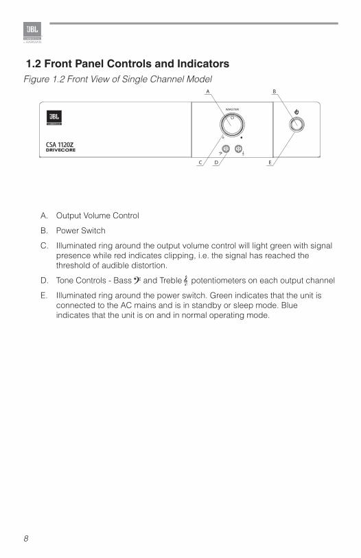
1.2 Front Panel Controls and Indicators
A. Output Volume Control
B. Power Switch
C. Illuminated ring around the output volume control will light green with signal presence while red indicates clipping, i.e. the signal has reached the threshold of audible distortion.
D. Tone Controls - Bass and Treble potentiometers on each output channel
E. Illuminated ring around the power switch. Green indicates that the unit is connected to the AC mains and is in standby or sleep mode. Blue indicates that the unit is on and in normal operating mode.
Figure 1.2 Front View of Single Channel ModelA B
EC D
CSA 1120z
9
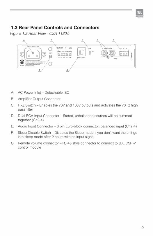
1.3 Rear Panel Controls and Connectors
A. AC Power Inlet – Detachable IEC
B. Amplifier Output Connector
C. Hi-Z Switch – Enables the 70V and 100V outputs and activates the 70Hz high pass filter
D. Dual RCA Input Connector – Stereo, unbalanced sources will be summed together (Ch2-4)
E. Audio Input Connector – 3 pin Euro-block connector, balanced input (Ch2-4)
F. Sleep Disable Switch – Disables the Sleep mode if you don’t want the unit go into sleep mode after 2 hours with no input signal.
G. Remote volume connector – RJ-45 style connector to connect to JBL CSR-V control module
Figure 1.3 Rear View - CSA 1120Z
A B C ED
F G
10
2.0 Setup
2.1 Unpacking Your Amplifier
Please unpack and inspect your amplifier for any damage that may have occurred during transit. If damage is found, notify the transportation company immediately. Only you can initiate a claim for shipping damage. We will be happy to help as needed. Save the shipping carton as evidence of damage for the shipper’s inspection.
We also recommend that you save all packing materials so you will have them if you ever need to transport the unit. Never ship the unit without the factory pack.
WARNING: Before you start to set up your amplifier, make sure you read and observe the Important Safety Instructions found at the beginning of this manual.
2.2 Installing Your Amplifier
CAUTION: Before you begin, make sure your amplifier is disconnected from the power source and all level controls turned completely down (counterclockwise).
To install the amplifier, you can use one of the following approaches:
• Rack mount the amplifier with the rack mounting kit, see Figure 2.2.2.
• Stack amps without using a cabinet. Rubber feet are included and can be attached onto the underside of the chassis. For amplifier dimensions, see Figure 2.2.1.
• We recommend that any sensitive equipment be located at least 8 inches (20cm) away from the amplifier.
11
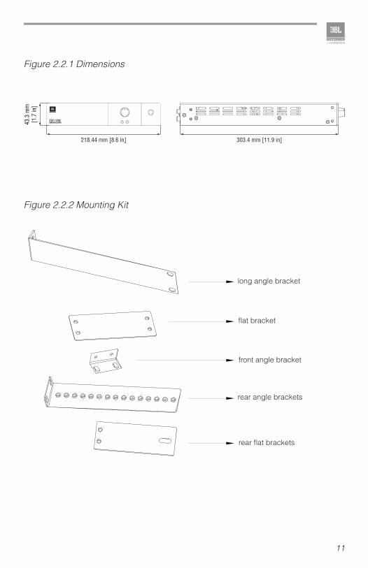
Figure 2.2.1 Dimensions
Figure 2.2.2 Mounting Kit
long angle bracket
flat bracket
front angle bracket
rear angle brackets
rear flat brackets
218.44 mm [8.6 in] 303.4 mm [11.9 in]
43.3
mm
[1
.7 in
]
CSA 1120z
12
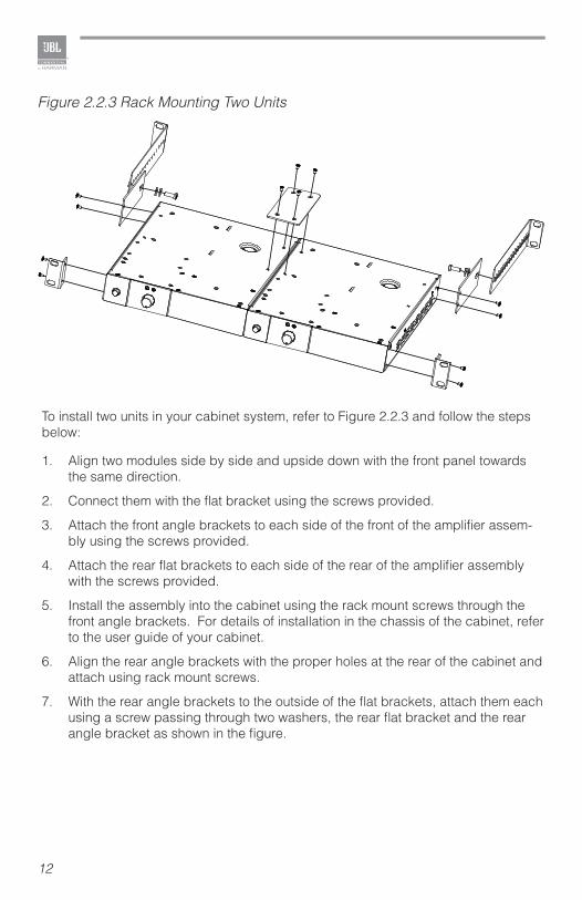
To install two units in your cabinet system, refer to Figure 2.2.3 and follow the steps below:
1. Align two modules side by side and upside down with the front panel towards the same direction.
2. Connect them with the flat bracket using the screws provided.
3. Attach the front angle brackets to each side of the front of the amplifier assem-bly using the screws provided.
4. Attach the rear flat brackets to each side of the rear of the amplifier assembly with the screws provided.
5. Install the assembly into the cabinet using the rack mount screws through the front angle brackets. For details of installation in the chassis of the cabinet, refer to the user guide of your cabinet.
6. Align the rear angle brackets with the proper holes at the rear of the cabinet and attach using rack mount screws.
7. With the rear angle brackets to the outside of the flat brackets, attach them each using a screw passing through two washers, the rear flat bracket and the rear angle bracket as shown in the figure.
Figure 2.2.3 Rack Mounting Two Units
13
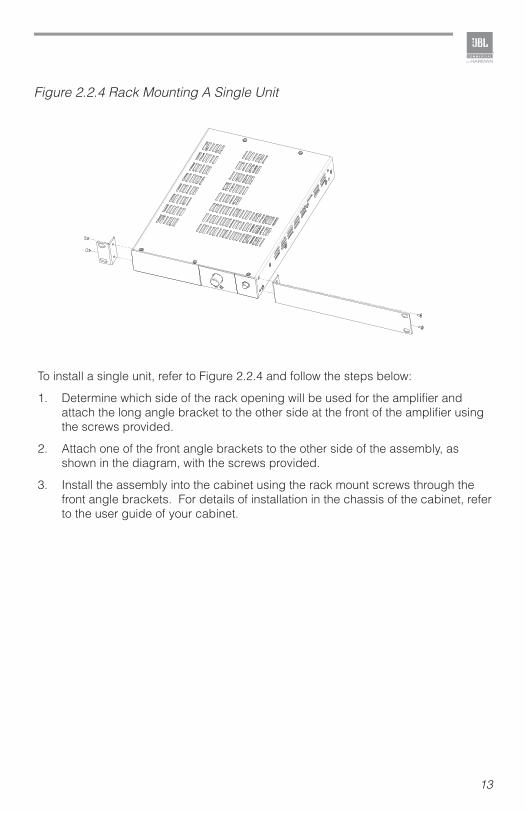
Figure 2.2.4 Rack Mounting A Single Unit
To install a single unit, refer to Figure 2.2.4 and follow the steps below:
1. Determine which side of the rack opening will be used for the amplifier and attach the long angle bracket to the other side at the front of the amplifier using the screws provided.
2. Attach one of the front angle brackets to the other side of the assembly, as shown in the diagram, with the screws provided.
3. Install the assembly into the cabinet using the rack mount screws through the front angle brackets. For details of installation in the chassis of the cabinet, refer to the user guide of your cabinet.
14
2.3 Ensuring Proper CoolingWhen using an equipment rack, keep a minimum space of 4 inches (10cm) from the top surface of the unit. Close any open spaces in the rack with blank panels. DO NOT block any air vents. The side walls of the rack should be a minimum of 2 inches (5 cm) from the amplifier sides. The back of the rack should be open.
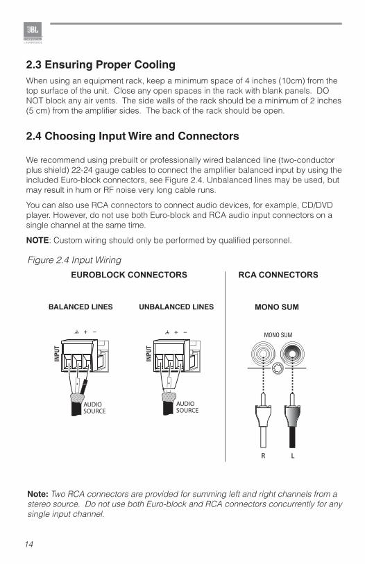
2.4 Choosing Input Wire and Connectors
We recommend using prebuilt or professionally wired balanced line (two-conductor plus shield) 22-24 gauge cables to connect the amplifier balanced input by using the included Euro-block connectors, see Figure 2.4. Unbalanced lines may be used, but may result in hum or RF noise very long cable runs.
You can also use RCA connectors to connect audio devices, for example, CD/DVD player. However, do not use both Euro-block and RCA audio input connectors on a single channel at the same time.
NOTE: Custom wiring should only be performed by qualified personnel.
MONO SUM
AUDIOSOURCE
AUDIOSOURCE
Figure 2.4 Input Wiring
Note: Two RCA connectors are provided for summing left and right channels from a stereo source. Do not use both Euro-block and RCA connectors concurrently for any single input channel.
15
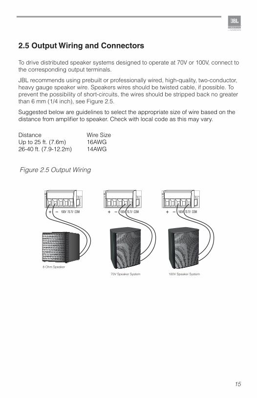
2.5 Output Wiring and Connectors
To drive distributed speaker systems designed to operate at 70V or 100V, connect to the corresponding output terminals.
JBL recommends using prebuilt or professionally wired, high-quality, two-conductor, heavy gauge speaker wire. Speakers wires should be twisted cable, if possible. To prevent the possibility of short-circuits, the wires should be stripped back no greater than 6 mm (1/4 inch), see Figure 2.5.
Suggested below are guidelines to select the appropriate size of wire based on the distance from amplifier to speaker. Check with local code as this may vary.
Distance Wire SizeUp to 25 ft. (7.6m) 16AWG26-40 ft. (7.9-12.2m) 14AWG
8 Ohm Speaker
100V Speaker System70V Speaker System
Figure 2.5 Output Wiring
16
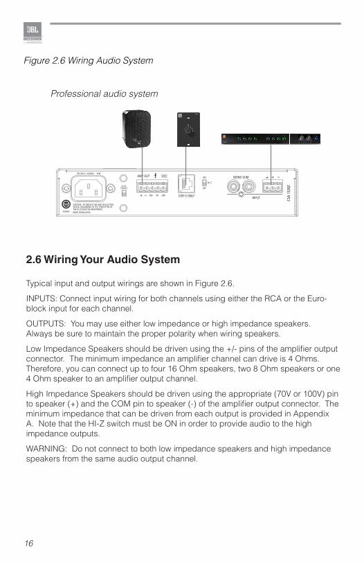
2.6 Wiring Your Audio System
Typical input and output wirings are shown in Figure 2.6.
INPUTS: Connect input wiring for both channels using either the RCA or the Euro-block input for each channel.
OUTPUTS: You may use either low impedance or high impedance speakers. Always be sure to maintain the proper polarity when wiring speakers.
Low Impedance Speakers should be driven using the +/- pins of the amplifier output connector. The minimum impedance an amplifier channel can drive is 4 Ohms. Therefore, you can connect up to four 16 Ohm speakers, two 8 Ohm speakers or one 4 Ohm speaker to an amplifier output channel.
High Impedance Speakers should be driven using the appropriate (70V or 100V) pin to speaker (+) and the COM pin to speaker (-) of the amplifier output connector. The minimum impedance that can be driven from each output is provided in Appendix A. Note that the HI-Z switch must be ON in order to provide audio to the high impedance outputs.
WARNING: Do not connect to both low impedance speakers and high impedance speakers from the same audio output channel.
Figure 2.6 Wiring Audio System
Professional audio system
LEVEL
CSR-V
17
2.7 Connecting to AC Mains
Connect your amplifier to the AC mains power source (power outlet) with the supplied AC power cord. First, connect the IEC end of the cord set to the IEC connector on the amplifier; then, plug the other end of the cord set to the AC mains. When properly connected to a live power source, the power ring should illuminate with a green color.
WARNING: The third prong of this connector (ground) is an important safety feature. Do not attempt to disable this ground connection by using an adapter or other methods.
Amplifiers don’t create energy. The AC mains voltage and current must be sufficient to deliver the power you expect. You must operate your amplifier from an AC mains power source with not more than a 10% variation above or below the specified line voltage and within the specified frequency range indicated on the back panel of the amplifier. If you are unsure of the output voltage of your AC mains, please consult your electrician.
2.8 Protecting Your Speakers
It’s wise to avoid clipping the amplifier signal. Not only does clipping sound bad, but it can damage high-frequency drivers. The built-in clip limiter prevents clipping.
Also, avoid sending strong subsonic signals to the amplifier. High-level, low-frequency signals from breath pops or dropped microphones can blow out drivers. You can switch to the HI-Z mode which, in addition to switching in the output transformers for 70V and 100V speakers, activates the high-pass filter. The filter prevents potentially damaging subsonic signals from going to the amplifier by eliminating signals below 70Hz.
2.9 Startup Procedure
Use the following procedure when first turning on your amplifier:1. Turn down the level of your audio source.2. Turn down the level controls of the amplifier.3. Power up the amplifier. The Power ring should change from green to blue.4. Turn up the level of your audio source to an optimum level.5. Turn up the Level controls on the amplifier until the desired loudness or power
level is achieved.
If you ever need to make any wiring or installation changes, don’t forget to disconnect the power cord.
18
3.0 Operation
3.1 Precautions
Your amplifier is protected from internal and external faults, but you should still take the following precautions for optimum performance and safety:
1. Before use, your amplifier first must be configured for proper operation, including input and output wiring hookup. Improper wiring can result in serious operating difficulties.For information on wiring and configuration, please consult the Setup section of this manual.
2. Use care when making connections, selecting signal sources and controlling the output level.
3. Always be sure to have all levels at minimum when connecting or disconnecting audio sources from the inputs. Failure to do so may cause the amplifier or speaker to go into a protection mode or even cause damage.
4. WARNING: Never connect the output to a power supply, battery or power main. Electrical shock may result.
5. Tampering with the circuitry, or making unauthorized circuit changes may be hazardous and invalidates all agency listings.
6. Do not operate the amplifier with the red Clip LEDs constantly flashing.7. Do not overdrive the mixer, which will cause clipped signal to be sent to
the amplifier. Such signals will be reproduced with extreme accuracy, and loudspeaker damage may result.
8. Do not operate the amplifier with less than the rated load impedance. Due to the amplifier’s output protection, such a configuration may result in premature clipping and speaker damage.
9. Use the amplifier in a well-ventilated environment and do not use it in ambient temperature conditions in excess of 40°C. Failure to do so will result in the auto disconnection from power supply, and the overheat auto protection function will be activated. The power indicator will become green and there will not be any audio signal coming out of the amplifier. In this case, turn down the volume to the minimum, and the amplifier will soon resume working. When the amplifier returns to normal temperature the power indicator will return to blue and you may turn the volume up to a safe level.
10. If the line voltage to the amplifier is too low, the low voltage protection function will be activated. The power light ring will change from blue to green.
CAUTION: JBL is not liable for damage that results from overdriving other system components.
19
3.2 Hi-Z Switch
When this switch is in the “OFF” position, the amplifier is configured to drive low impedance speakers, (4 Ohms ,minimum) The Hi-Z switch will switch in the built-in output transformer allowing the unit to drive 70V or 100V speaker systems directly when connected to the appropriate output terminals. As an added feature when driving the high impedance speakers, the system automatically switches in a 70Hz high pass filter.
3.3 Remote Volume Control
Remote volume control can be implemented using a CSR-V controller connected via an Ethernet cable to the RJ45 connector on the back panel. For the CSA 240Z, CSA 280Z and CSA 2120Z, there are two connectors, one for each amplifier output.
3.4 Sleep Mode
To save energy, the unit is designed to go into sleep mode after approximately 2 hours operating with no signal at any of the inputs. Return of signal (-36dBu) to any input will wake the unit from its slumber. The sleep mode can be disabled by activating the Sleep Disable switch on the rear panel.
20
4.0 Troubleshooting
CONDITION: No power to the amplifier so that the power ring is not illuminated.
POSSIBLE REASON: The amplifier is not plugged into the power receptacle
CONDITION: No sound or low sound.
POSSIBLE REASON: The input signal is not present or at a very low level.
POSSIBLE REASON: The Master Volume control is turned down.
POSSIBLE REASON: A CSR-V is connected and turned down.
POSSIBLE REASON: The Hi-Z switch is OFF while using the 70V or 100V outputs.
POSSIBLE REASON: The power switch is OFF. (Note that while plugged in, the amplifier will be in standby mode and the power ring will be green until the power switch is activated and the power ring will turn blue.)
CONDITION: Distorted sound.
POSSIBLE REASON: Input signal level is too high. Please turn down the input level controls. Note that theamplifier should not be operated at a level that allows the clip indicator to be constantly ON.
POSSIBLE REASON: Master Volume is too high.
21
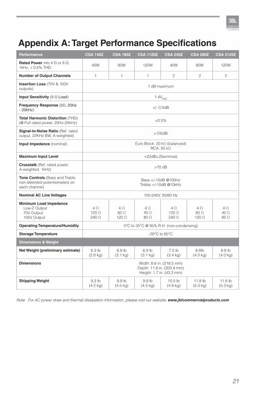
Appendix A: Target Performance SpecificationsPerformance CSA 140Z CSA 180Z CSA 1120Z CSA 240Z CSA 280Z CSA 2120Z
Rated Power into 4 Ω or 8 Ω; 1kHz, ≤ 0.5% THD 40W 80W 120W 40W 80W 120W
Number of Output Channels 1 1 1 2 2 2
Insertion Loss (70V & 100V outputs) 1 dB maximum
Input Sensitivity (8 Ω Load) 1.4VRMS
Frequency Response (8Ω, 20Hz - 20kHz) +/- 0.5dB
Total Harmonic Distortion (THD) (@ Full rated power, 20Hz-20kHz) <0.5%
Signal-to-Noise Ratio (Ref. rated output, 22KHz BW, A-weighted) >100dB
Input Impedance (nominal) Euro Block: 20 kΩ (balanced) RCA: 50 kΩ
Maximum Input Level +22dBu (Norminal)
Crosstalk (Ref. rated power, A-weighted, 1kHz) >70 dB
Tone Controls (Bass and Treble non-detented potentiometers on each channel)
Bass +/-10dB @100HzTreble +/-10dB @10kHz
Nominal AC Line Voltages 100-240V, 50/60 Hz
Minimum Load Impedance Low-Z Output 70V Output 100V Output
4 Ω 120 Ω240 Ω
4 Ω 60 Ω120 Ω
4 Ω40 Ω80 Ω
4 Ω120 Ω240 Ω
4 Ω60 Ω120 Ω
4 Ω40 Ω80 Ω
Operating Temperature/Humidity 0°C to 35°C @ 95% R.H. (non-condensing)
Storage Temperature -20°C to 85°C
Dimensions & Weight
Net Weight (preliminary estimate) 6.3 lb(2.8 kg)
6.9 lb(3.1 kg)
6.9 lb (3.1 kg)
7.5 lb(3.4 kg)
8.8lb (4.0 kg)
8.8 lb(4.0 kg)
Dimensions Width: 8.6 in. (218.5 mm) Depth: 11.9 in. (303.4 mm)Height: 1.7 in. (43.3 mm)
Shipping Weight 9.3 lb(4.2 kg)
9.9 lb (4.5 kg)
9.9 lb(4.5 kg)
10.5 lb (4.8 kg)
11.8 lb(5.3 kg)
11.8 lb(5.3 kg)
Note: For AC power draw and thermal dissipation information, please visit our website. www.jblcommercialproducts.com

22
Appendix B: Contact Information
For additional information, please consult JBL Professional Customer Service, your system installer or retailer.
On The World Wide Web:www.jblcommercialproducts.com
Professional Contacts, Outside the USA:Contact the JBL Professional Distributor in your area. A complete list of JBL Professional international distributors is provided at our U.S.A. Website: www.jblpro.com

23

Part Number:5040963 Issue: 01/14
JBL Commercial8760 South Sandy Pkwy. Sandy, UT 84070 USA(801) 566-8800