Embed Size (px)
Citation preview
ALSPA MV DELTA
Liquid Cooled Drive System
Technical Manual
ForMVRL2100-4601
&MVDL643-4701
690 V a.c. rated products
Publication No. T1693ENIssue 1 (07/00)
Issue Information ALSPA MV Liquid Cooled DELTA
Page ii T1693EN Issue (07/00)
Acknowledgements
“1-wire TM” is a trademark of Dallas Semiconductors of the USA.
Issue Information
Publication T1693EN Issue 1 (07/00)
© - ALSTOM - 2000. ALSTOM, the logo ALSTOM and their frameworks aretrademarks and service trademark applications of ALSTOM. The other namesmentioned, registered or not, are the property of their respective companies.
ALSPA MV Liquid Cooled DELTA Safety Instructions
Issue (07/00) T1693EN Page iii
SAFETY INSTRUCTIONS
Care has been taken with the design of this product to ensure that it is safe. However,in common with all products of this type, misuse can result in injury or death.Therefore, it is very important that the instructions in this manual and on the productare observed during transportation, commissioning, operation, maintenance anddisposal.
This technical manual should be regarded as part of the product. It should be storedwith the product and passed on to any subsequent owner or user.
Local safety laws and regulations must always be observed.
Persons working on the product must be suitably skilled and should have been trainedin that work for these products.
The product is a component designed for incorporation in installations, apparatus andmachines.
The product must not be used as a single item safety system. In applications wheremaloperation of the product could cause danger, additional means must be used toprevent danger to persons.
Product approvals and certifications will be invalidated if the product is transported,used or stored outside its ratings or if the instructions in this manual are not observed.
Third party approvals to safety standards UL 508C and CSA C22.2 No 14 are markedon the product.
In the European Union:
• Products within the scope of the Low Voltage Directive, 73/23/EEC as amended areCE marked.
• The product complies with the essential protection requirements of the EMC directive
89/336/EEC as amended, when installed and used as described in this manual.The requirements of the EMC Directive should be established before any installation,apparatus or machine which incorporates the product is taken into service.
• A machine should not be taken into service until the machine has been declared in
conformity with the provisions of the Machinery (Safety) Directive, 98/37/EEC.
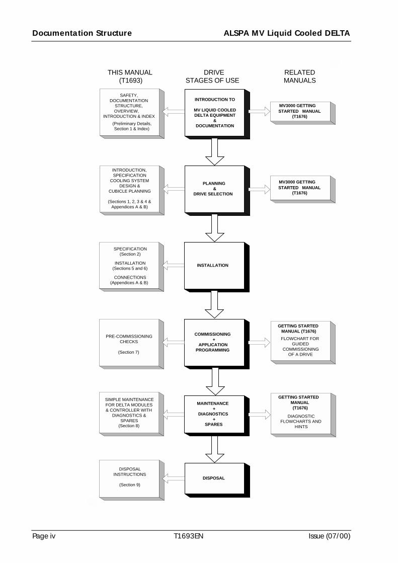
Documentation Structure ALSPA MV Liquid Cooled DELTA
Page iv T1693EN Issue (07/00)
THIS MANUAL(T1693)
DRIVESTAGES OF USE
RELATEDMANUALS
PLANNING&
DRIVE SELECTION
INSTALLATION
COMMISSIONING+
APPLICATIONPROGRAMMING
DISPOSAL
INTRODUCTION,SPECIFICATION
COOLING SYSTEMDESIGN &
CUBICLE PLANNING
(Sections 1, 2, 3 & 4 &Appendices A & B)
SPECIFICATION(Section 2)
INSTALLATION(Sections 5 and 6)
CONNECTIONS(Appendices A & B)
PRE-COMMISSIONINGCHECKS
(Section 7)
SIMPLE MAINTENANCEFOR DELTA MODULES& CONTROLLER WITH
DIAGNOSTICS &SPARES
(Section 8)
DISPOSALINSTRUCTIONS
(Section 9)
MV3000 GETTINGSTARTED MANUAL
(T1676)
INTRODUCTION TO
MV LIQUID COOLEDDELTA EQUIPMENT
&DOCUMENTATION
MV3000 GETTINGSTARTED MANUAL
(T1676)
GETTING STARTEDMANUAL (T1676)FLOWCHART FOR
GUIDEDCOMMISSIONING
OF A DRIVE
SAFETY,DOCUMENTATION
STRUCTURE,OVERVIEW,
INTRODUCTION & INDEX(Preliminary Details,Section 1 & Index)
MAINTENANCE+
DIAGNOSTICS+
SPARES
GETTING STARTEDMANUAL(T1676)
DIAGNOSTICFLOWCHARTS AND
HINTS
ALSPA MV Liquid Cooled DELTA Scope
Issue (07/00) T1693EN Page v
SCOPE
This publication provides assembly, installation, commissioning and maintenanceinstructions for MV Liquid Cooled DELTA Rectifier and Transistor power equipmentwhen supplied in kitted form and for the associated MV3000 controller. Guidance isalso given for design of the external cooling system for use with the Liquid CooledDELTA equipment.
This publication should be read in conjunction with the appropriate MV3000 GettingStarted Manual T1676. Both publications should be regarded as part of the ALSPA MVLiquid Cooled DELTA product. They should be retained for the life of the product andpassed on to any subsequent owner or user.
Scope ALSPA MV Liquid Cooled DELTA
Page vi T1693EN Issue (07/00)
(This page intentionally left blank)
ALSPA MV Liquid Cooled DELTA Units Covered
Issue (07/00) T1693EN Page vii
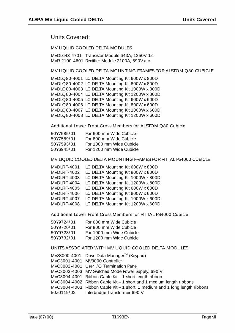
Units Covered:
MV LIQUID COOLED DELTA MODULES
MVDL643-4701 Transistor Module 643A, 1250V d.c.MVRL2100-4601 Rectifier Module 2100A, 690V a.c.
MV LIQUID COOLED DELTA MOUNTING FRAMES FOR ALSTOM Q80 CUBICLE
MVDLQ80-4001 LC DELTA Mounting Kit 600W x 800DMVDLQ80-4002 LC DELTA Mounting Kit 800W x 800DMVDLQ80-4003 LC DELTA Mounting Kit 1000W x 800DMVDLQ80-4004 LC DELTA Mounting Kit 1200W x 800DMVDLQ80-4005 LC DELTA Mounting Kit 600W x 600DMVDLQ80-4006 LC DELTA Mounting Kit 800W x 600DMVDLQ80-4007 LC DELTA Mounting Kit 1000W x 600DMVDLQ80-4008 LC DELTA Mounting Kit 1200W x 600D
Additional Lower Front Cross Members for ALSTOM Q80 Cubicle
50Y7585/01 For 600 mm Wide Cubicle50Y7589/01 For 800 mm Wide Cubicle50Y7593/01 For 1000 mm Wide Cubicle50Y6945/01 For 1200 mm Wide Cubicle
MV LIQUID COOLED DELTA MOUNTING FRAMES FOR RITTAL PS4000 CUBICLE
MVDLRIT-4001 LC DELTA Mounting Kit 600W x 800DMVDLRIT-4002 LC DELTA Mounting Kit 800W x 800DMVDLRIT-4003 LC DELTA Mounting Kit 1000W x 800DMVDLRIT-4004 LC DELTA Mounting Kit 1200W x 800DMVDLRIT-4005 LC DELTA Mounting Kit 600W x 600DMVDLRIT-4006 LC DELTA Mounting Kit 800W x 600DMVDLRIT-4007 LC DELTA Mounting Kit 1000W x 600DMVDLRIT-4008 LC DELTA Mounting Kit 1200W x 600D
Additional Lower Front Cross Members for RITTAL PS4000 Cubicle
50Y9724/01 For 600 mm Wide Cubicle50Y9720/01 For 800 mm Wide Cubicle50Y9728/01 For 1000 mm Wide Cubicle50Y9732/01 For 1200 mm Wide Cubicle
UNITS ASSOCIATED WITH MV LIQUID COOLED DELTA MODULES
MVS3000-4001 Drive Data ManagerTM (Keypad)MVC3001-4001 MV3000 ControllerMVC3002-4001 User I/O Termination PanelMVC3003-4003 MV Switched Mode Power Supply, 690 VMVC3004-4001 Ribbon Cable Kit – 1 short length ribbonMVC3004-4002 Ribbon Cable Kit – 1 short and 1 medium length ribbonsMVC3004-4003 Ribbon Cable Kit – 1 short, 1 medium and 1 long length ribbons50Z0119/02 Interbridge Transformer 690 V
Overview ALSPA MV Liquid Cooled DELTA
Page viii T1693EN Issue (07/00)
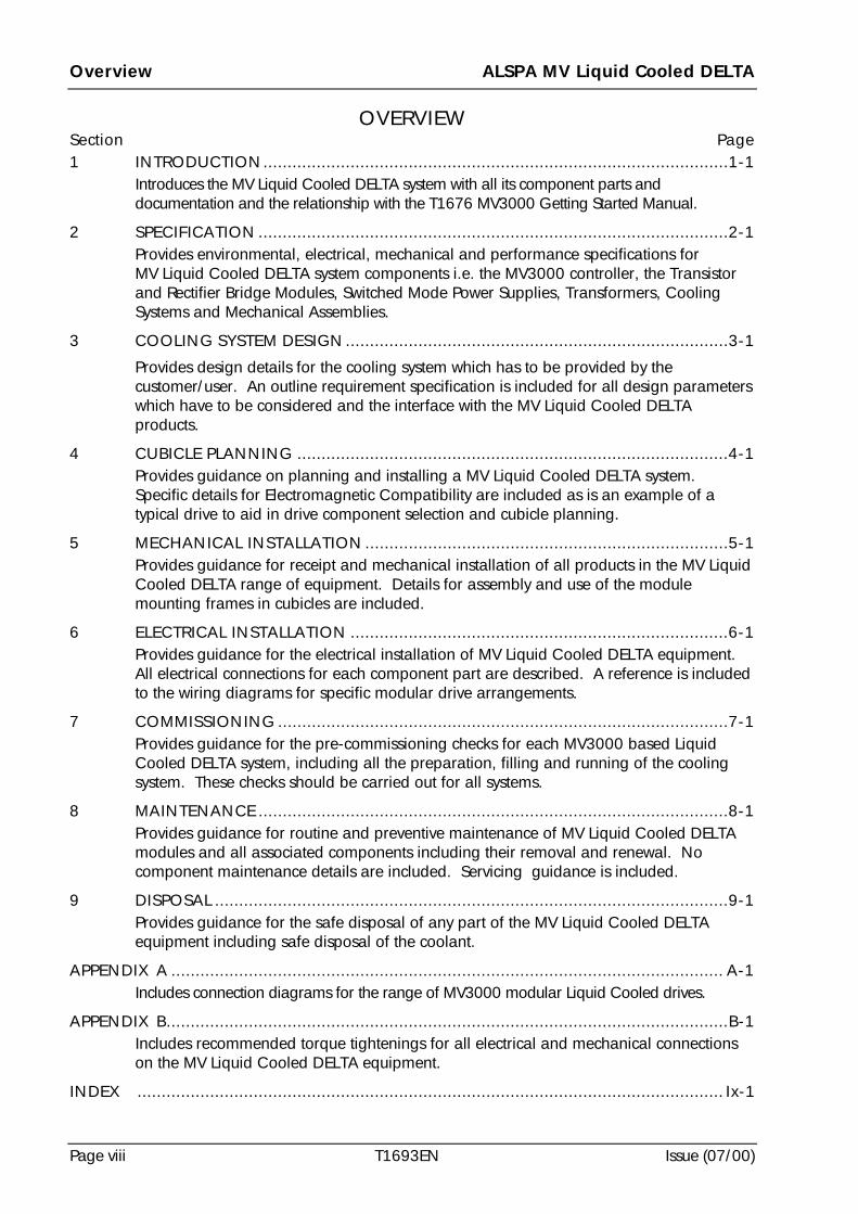
OVERVIEWSection Page1 INTRODUCTION................................................................................................1-1
Introduces the MV Liquid Cooled DELTA system with all its component parts anddocumentation and the relationship with the T1676 MV3000 Getting Started Manual.
2 SPECIFICATION .................................................................................................2-1Provides environmental, electrical, mechanical and performance specifications forMV Liquid Cooled DELTA system components i.e. the MV3000 controller, the Transistorand Rectifier Bridge Modules, Switched Mode Power Supplies, Transformers, CoolingSystems and Mechanical Assemblies.
3 COOLING SYSTEM DESIGN...............................................................................3-1
Provides design details for the cooling system which has to be provided by thecustomer/user. An outline requirement specification is included for all design parameterswhich have to be considered and the interface with the MV Liquid Cooled DELTAproducts.
4 CUBICLE PLANNING .........................................................................................4-1Provides guidance on planning and installing a MV Liquid Cooled DELTA system.Specific details for Electromagnetic Compatibility are included as is an example of atypical drive to aid in drive component selection and cubicle planning.
5 MECHANICAL INSTALLATION ...........................................................................5-1Provides guidance for receipt and mechanical installation of all products in the MV LiquidCooled DELTA range of equipment. Details for assembly and use of the modulemounting frames in cubicles are included.
6 ELECTRICAL INSTALLATION ..............................................................................6-1Provides guidance for the electrical installation of MV Liquid Cooled DELTA equipment.All electrical connections for each component part are described. A reference is includedto the wiring diagrams for specific modular drive arrangements.
7 COMMISSIONING .............................................................................................7-1Provides guidance for the pre-commissioning checks for each MV3000 based LiquidCooled DELTA system, including all the preparation, filling and running of the coolingsystem. These checks should be carried out for all systems.
8 MAINTENANCE .................................................................................................8-1Provides guidance for routine and preventive maintenance of MV Liquid Cooled DELTAmodules and all associated components including their removal and renewal. Nocomponent maintenance details are included. Servicing guidance is included.
9 DISPOSAL ..........................................................................................................9-1Provides guidance for the safe disposal of any part of the MV Liquid Cooled DELTAequipment including safe disposal of the coolant.
APPENDIX A .................................................................................................................. A-1Includes connection diagrams for the range of MV3000 modular Liquid Cooled drives.
APPENDIX B....................................................................................................................B-1Includes recommended torque tightenings for all electrical and mechanical connectionson the MV Liquid Cooled DELTA equipment.
INDEX ......................................................................................................................... Ix-1
ALSPA MV Liquid Cooled DELTA Contents
Issue (07/00) T1693EN Page ix
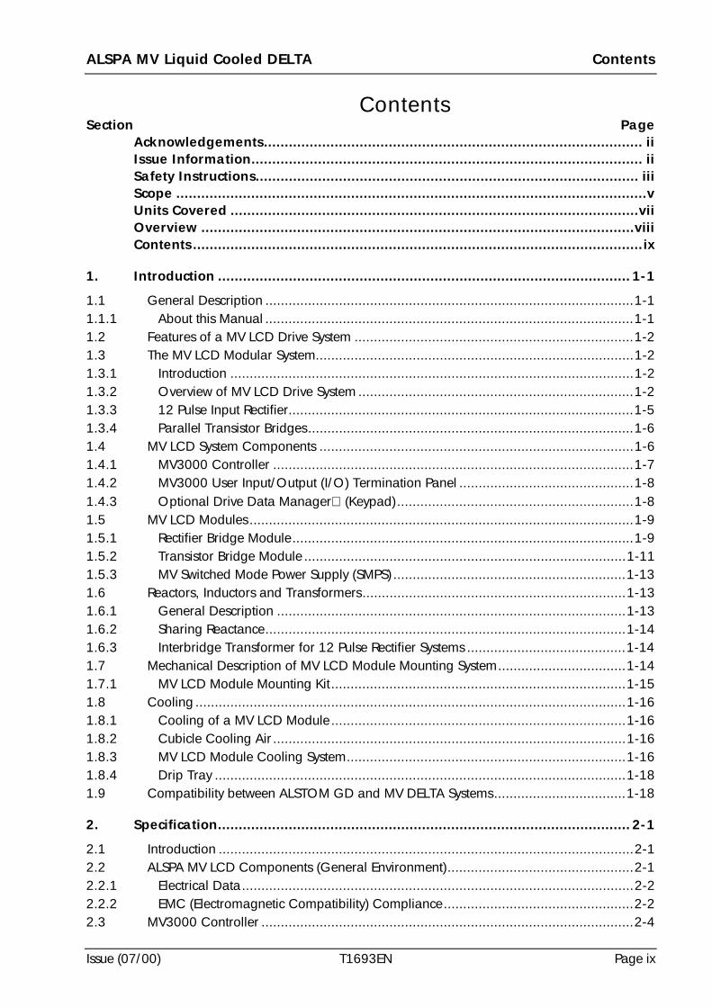
ContentsSection Page
Acknowledgements........................................................................................... iiIssue Information.............................................................................................. iiSafety Instructions............................................................................................ iiiScope .................................................................................................................vUnits Covered ..................................................................................................viiOverview ........................................................................................................viiiContents ............................................................................................................ix
1. Introduction ................................................................................................... 1-1
1.1 General Description ...............................................................................................1-11.1.1 About this Manual ...............................................................................................1-11.2 Features of a MV LCD Drive System ........................................................................1-21.3 The MV LCD Modular System..................................................................................1-21.3.1 Introduction ........................................................................................................1-21.3.2 Overview of MV LCD Drive System .......................................................................1-21.3.3 12 Pulse Input Rectifier.........................................................................................1-51.3.4 Parallel Transistor Bridges....................................................................................1-61.4 MV LCD System Components .................................................................................1-61.4.1 MV3000 Controller .............................................................................................1-71.4.2 MV3000 User Input/Output (I/O) Termination Panel .............................................1-81.4.3 Optional Drive Data Manager (Keypad).............................................................1-81.5 MV LCD Modules ...................................................................................................1-91.5.1 Rectifier Bridge Module........................................................................................1-91.5.2 Transistor Bridge Module ...................................................................................1-111.5.3 MV Switched Mode Power Supply (SMPS) ............................................................1-131.6 Reactors, Inductors and Transformers....................................................................1-131.6.1 General Description ..........................................................................................1-131.6.2 Sharing Reactance.............................................................................................1-141.6.3 Interbridge Transformer for 12 Pulse Rectifier Systems .........................................1-141.7 Mechanical Description of MV LCD Module Mounting System.................................1-141.7.1 MV LCD Module Mounting Kit............................................................................1-151.8 Cooling ...............................................................................................................1-161.8.1 Cooling of a MV LCD Module ............................................................................1-161.8.2 Cubicle Cooling Air ...........................................................................................1-161.8.3 MV LCD Module Cooling System........................................................................1-161.8.4 Drip Tray ..........................................................................................................1-181.9 Compatibility between ALSTOM GD and MV DELTA Systems..................................1-18
2. Specification................................................................................................... 2-1
2.1 Introduction ...........................................................................................................2-12.2 ALSPA MV LCD Components (General Environment)................................................2-12.2.1 Electrical Data.....................................................................................................2-22.2.2 EMC (Electromagnetic Compatibility) Compliance.................................................2-22.3 MV3000 Controller ................................................................................................2-4
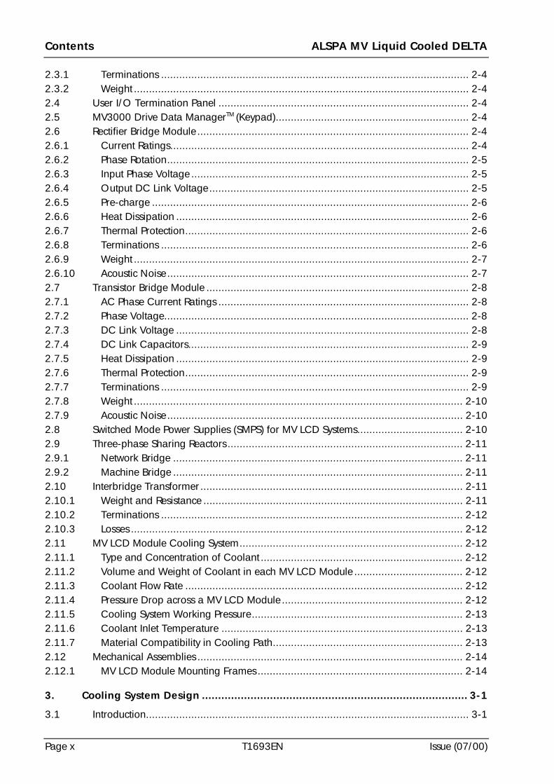
Contents ALSPA MV Liquid Cooled DELTA
Page x T1693EN Issue (07/00)
2.3.1 Terminations ...................................................................................................... 2-42.3.2 Weight ............................................................................................................... 2-42.4 User I/O Termination Panel ................................................................................... 2-42.5 MV3000 Drive Data ManagerTM (Keypad)................................................................ 2-42.6 Rectifier Bridge Module .......................................................................................... 2-42.6.1 Current Ratings................................................................................................... 2-42.6.2 Phase Rotation.................................................................................................... 2-52.6.3 Input Phase Voltage ............................................................................................ 2-52.6.4 Output DC Link Voltage...................................................................................... 2-52.6.5 Pre-charge ......................................................................................................... 2-62.6.6 Heat Dissipation ................................................................................................. 2-62.6.7 Thermal Protection.............................................................................................. 2-62.6.8 Terminations ...................................................................................................... 2-62.6.9 Weight ............................................................................................................... 2-72.6.10 Acoustic Noise.................................................................................................... 2-72.7 Transistor Bridge Module ....................................................................................... 2-82.7.1 AC Phase Current Ratings ................................................................................... 2-82.7.2 Phase Voltage..................................................................................................... 2-82.7.3 DC Link Voltage ................................................................................................. 2-82.7.4 DC Link Capacitors............................................................................................. 2-92.7.5 Heat Dissipation ................................................................................................. 2-92.7.6 Thermal Protection.............................................................................................. 2-92.7.7 Terminations ...................................................................................................... 2-92.7.8 Weight ............................................................................................................. 2-102.7.9 Acoustic Noise.................................................................................................. 2-102.8 Switched Mode Power Supplies (SMPS) for MV LCD Systems................................... 2-102.9 Three-phase Sharing Reactors .............................................................................. 2-112.9.1 Network Bridge ................................................................................................ 2-112.9.2 Machine Bridge ................................................................................................ 2-112.10 Interbridge Transformer ....................................................................................... 2-112.10.1 Weight and Resistance ...................................................................................... 2-112.10.2 Terminations .................................................................................................... 2-122.10.3 Losses .............................................................................................................. 2-122.11 MV LCD Module Cooling System.......................................................................... 2-122.11.1 Type and Concentration of Coolant ................................................................... 2-122.11.2 Volume and Weight of Coolant in each MV LCD Module .................................... 2-122.11.3 Coolant Flow Rate ............................................................................................ 2-122.11.4 Pressure Drop across a MV LCD Module ............................................................ 2-122.11.5 Cooling System Working Pressure...................................................................... 2-132.11.6 Coolant Inlet Temperature ................................................................................ 2-132.11.7 Material Compatibility in Cooling Path............................................................... 2-132.12 Mechanical Assemblies ........................................................................................ 2-142.12.1 MV LCD Module Mounting Frames .................................................................... 2-14
3. Cooling System Design .................................................................................. 3-1
3.1 Introduction........................................................................................................... 3-1
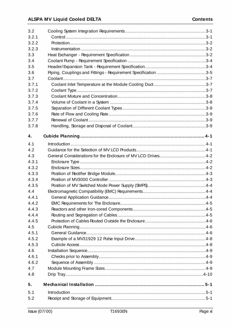
ALSPA MV Liquid Cooled DELTA Contents
Issue (07/00) T1693EN Page xi
3.2 Cooling System Integration Requirements ................................................................3-13.2.1 Control ...............................................................................................................3-13.2.2 Protection............................................................................................................3-23.2.3 Instrumentation ...................................................................................................3-23.3 Heat Exchanger - Requirement Specification ............................................................3-23.4 Coolant Pump - Requirement Specification ..............................................................3-43.5 Header/Expansion Tank - Requirement Specification................................................3-43.6 Piping, Couplings and Fittings - Requirement Specification .......................................3-53.7 Coolant .................................................................................................................3-73.7.1 Coolant Inlet Temperature at the Module Cooling Duct .........................................3-73.7.2 Coolant Type ......................................................................................................3-73.7.3 Coolant Mixture and Concentration......................................................................3-83.7.4 Volume of Coolant in a System ............................................................................3-83.7.5 Separation of Different Coolant Types ..................................................................3-93.7.6 Rate of Flow and Cooling Rate .............................................................................3-93.7.7 Renewal of Coolant .............................................................................................3-93.7.8 Handling, Storage and Disposal of Coolant..........................................................3-9
4. Cubicle Planning............................................................................................ 4-1
4.1 Introduction ...........................................................................................................4-14.2 Guidance for the Selection of MV LCD Products .......................................................4-14.3 General Considerations for the Enclosure of MV LCD Drives.....................................4-24.3.1 Enclosure Type ....................................................................................................4-24.3.2 Enclosure Sizes....................................................................................................4-24.3.3 Position of Rectifier Bridge Module........................................................................4-34.3.4 Position of MV3000 Controller .............................................................................4-34.3.5 Position of MV Switched Mode Power Supply (SMPS)..............................................4-44.4 Electromagnetic Compatibility (EMC) Requirements..................................................4-44.4.1 General Application Guidance.............................................................................4-44.4.2 EMC Requirements for The Enclosure....................................................................4-54.4.3 Reactors and other Iron-cored Components..........................................................4-54.4.4 Routing and Segregation of Cables ......................................................................4-54.4.5 Protection of Cables Routed Outside the Enclosure ................................................4-64.5 Cubicle Planning....................................................................................................4-64.5.1 General Guidance...............................................................................................4-64.5.2 Example of a MV31929 12 Pulse Input Drive ........................................................4-84.5.3 Cubicle Access ....................................................................................................4-84.6 Installation Sequence..............................................................................................4-94.6.1 Checks prior to Assembly.....................................................................................4-94.6.2 Sequence of Assembly .........................................................................................4-94.7 Module Mounting Frame Sizes ................................................................................4-94.8 Drip Tray .............................................................................................................4-10
5. Mechanical Installation ................................................................................. 5-1
5.1 Introduction ...........................................................................................................5-15.2 Receipt and Storage of Equipment...........................................................................5-1
Contents ALSPA MV Liquid Cooled DELTA
Page xii T1693EN Issue (07/00)
5.3 Cooling Requirements ........................................................................................... 5-25.4 Module Mounting Frame Dimensions ..................................................................... 5-25.5 Assembling Module Mounting Frames for Q80 Cubicles.......................................... 5-35.5.1 General ............................................................................................................. 5-35.5.2 Side Supports for 600 or 800 mm (23.6 in or 31.5 in) Deep Cubicles ................... 5-35.5.3 Cross Members .................................................................................................. 5-35.6 Assembling Module Mounting Frames for Rittal PS4000 Cubicles............................. 5-65.6.1 General ............................................................................................................. 5-65.6.2 Side Supports for 600 or 800 mm (23.6 in or 31.5 in) Deep Cubicles ................... 5-65.6.3 Cross Members .................................................................................................. 5-65.7 Lower Guide Plates................................................................................................ 5-85.8 Drip Tray .............................................................................................................. 5-85.9 Modules (Transistor and Rectifier Bridges) ............................................................... 5-85.9.1 Guidance for Handling ....................................................................................... 5-85.9.2 Module Lifting Procedure .................................................................................... 5-85.9.3 Transistor Modules - fitting a busbar ................................................................. 5-145.9.4 Fitting of Shrouds.............................................................................................. 5-145.10 Mounting a MV3000 Controller in a Cubicle......................................................... 5-145.11 Installation of the Drive Data Manager (Keypad)................................................. 5-155.12 Installation of the User I/O Termination Panel ....................................................... 5-155.13 Installation of a MV3000 Switched Mode Power Supply (SMPS) .............................. 5-185.14 Mounting the Interbridge Transformer (50Z0119/02) ............................................ 5-195.15 Cable Connections between MV LCD Modules and MV3000 Controller ................. 5-195.16 Piping Connections for Cooling System................................................................. 5-205.16.1 Piping and Couplings....................................................................................... 5-205.16.2 Recommendations for Routing Pipes into a Cubicle ............................................ 5-215.16.3 Recommendations for Routing Pipes into Multi-cubicle Suites .............................. 5-215.16.4 Retention and Fitting of Pipe in a Cubicle .......................................................... 5-215.16.5 Vent Valves...................................................................................................... 5-225.16.6 Application Specific Warnings for High Temperatures on a Piping System ............ 5-225.17 Installation of Electrical Equipment for the Liquid Cooling System........................... 5-22
6. Electrical Installation ..................................................................................... 6-1
6.1 Introduction........................................................................................................... 6-16.2 Rectifier Bridge Module Terminals........................................................................... 6-26.2.1 Control Terminals ............................................................................................... 6-36.2.2 Power Terminals for MVRL2100 Rectifier Bridge Module........................................ 6-36.3 Transistor Bridge Module Terminals........................................................................ 6-56.3.1 Control Connections ........................................................................................... 6-66.3.2 Power Terminals for MVDL643 Transistor Bridge Module ...................................... 6-76.3.3 AC Power Cables................................................................................................ 6-76.4 Connections to the Interbridge Transformer ............................................................ 6-86.5 Module Earthing/Grounding Requirements ............................................................. 6-86.6 Line Contactors and Relays .................................................................................... 6-86.7 MV3000 Controller................................................................................................ 6-96.8 Connections to the Drive Data Manager (Keypad) .............................................. 6-11
ALSPA MV Liquid Cooled DELTA Contents
Issue (07/00) T1693EN Page xiii
6.9 Connections to the User Input/Output (I/O) Termination Panel ...............................6-116.10 MV3000 Switched Mode Power Supply (SMPS).......................................................6-146.11 Fuses for Rectifier and Transistor Module Applications............................................6-146.11.1 Rectifier Bridge Module Input Fuse Protection ......................................................6-146.11.2 Transistor Bridge Module DC Link Fuse Protection...............................................6-156.11.3 Fuse Selection and Mounting .............................................................................6-156.11.4 Microswitch Attachment .....................................................................................6-166.12 Installation of Electrical Equipment for the Liquid Cooling System............................6-16
7. Commissioning .............................................................................................. 7-1
7.1 Introduction ...........................................................................................................7-17.2 Pre-commissioning Checks .....................................................................................7-27.2.1 Mechanical Checks..............................................................................................7-27.2.2 Electrical Checks .................................................................................................7-27.3 Insulation Tests ......................................................................................................7-37.3.1 Equipment Groups ..............................................................................................7-37.3.2 Preliminary Checks Prior to Carrying Out Insulation Voltage Tests ..........................7-47.3.3 Insulation Tests for each Group............................................................................7-47.4 Preparation of the Cooling System ..........................................................................7-67.4.1 Initial Checks prior to Coolant Loading.................................................................7-67.4.2 Initial Tests prior to Running the Cooling System ...................................................7-67.5 Filling the Cooling System.......................................................................................7-67.5.1 Precautions .........................................................................................................7-67.5.2 Procedure ...........................................................................................................7-67.6 Running the Coolant Pump only..............................................................................7-77.7 Checks for Instrumentation and Controls .................................................................7-87.8 Commissioning......................................................................................................7-87.9 Coolant Temperature Checks During Commissioning ..............................................7-8
8. Maintenance.................................................................................................. 8-1
8.1 Introduction ...........................................................................................................8-18.2 Special Tools, Equipment and Materials ..................................................................8-18.2.1 For the MV LCD Module (Transistor or Rectifier Bridge)..........................................8-18.2.2 For the MV3000 Controller ..................................................................................8-28.2.3 For Packing a MV LCD Module or a MV3000 Controller........................................8-28.3 Disconnection of Electrical Supplies from a MV LCD Module.....................................8-38.3.1 Preliminary Checks ..............................................................................................8-48.3.2 Recommended Procedure for Disconnection of Wiring from a Module....................8-48.4 Removal of a MV LCD Module from a Cubicle.........................................................8-48.5 Transporting a MV LCD Module..............................................................................8-68.5.1 Preparation of the MV LCD Module for Shipping...................................................8-68.5.2 Packing a MV LCD Module for Shipping ...............................................................8-78.6 Fitting a MV LCD Module into a Mounting Frame in a Cubicle..................................8-88.7 Re-connection of a MV LCD Rectifier Module ...........................................................8-98.8 Re-connection of a MV LCD Transistor Module ........................................................8-98.9 Removal of a MV3000 Controller from a Cubicle.....................................................8-9
Contents ALSPA MV Liquid Cooled DELTA
Page xiv T1693EN Issue (07/00)
8.10 Transporting a MV3000 Controller....................................................................... 8-108.11 Fitting and Re-connecting a MV3000 Controller in a Cubicle ................................. 8-108.12 Removal of a SMPS from a MV LCD Transistor Module .......................................... 8-108.13 Fitting a SMPS to a MV LCD Transistor Module...................................................... 8-118.14 Removal of a User I/O Termination Panel ............................................................. 8-118.15 Fitting a User I/O Termination Panel .................................................................... 8-118.16 Handling, Storage and Disposal of Coolant .......................................................... 8-118.16.1 Handling of Coolant ......................................................................................... 8-118.16.2 Storage of Coolant ........................................................................................... 8-128.16.3 Disposal of Coolant .......................................................................................... 8-128.17 Preventive Maintenance ....................................................................................... 8-128.17.1 Monthly Checks - With the Power Off ................................................................ 8-128.17.2 Six Monthly Checks - With the Power Off........................................................... 8-138.17.3 Periodic Checks of the Cooling System - With the Power Off............................... 8-138.17.4 Renewal of Coolant - With the Power Off .......................................................... 8-138.17.5 Cleaning of a Strainer ...................................................................................... 8-148.18 Diagnostics at the MV3000 Controller .................................................................. 8-148.19 Diagnostics at the MV LCD Transistor Module ....................................................... 8-148.20 Spares and Servicing ........................................................................................... 8-158.20.1 Spares ............................................................................................................. 8-158.20.2 Servicing .......................................................................................................... 8-158.20.3 Pre-charge Fuses .............................................................................................. 8-158.21 Capacitor Reforming ........................................................................................... 8-15
9. Disposal......................................................................................................... 9-1
LIST OF FIGURES
1-1 Typical Cubicle Layout For MV LCD System Component Parts .................................. 1-31-2 Interconnections between a MV3000 Controller and MV LCD Modules..................... 1-41-3 Block Diagram for an AC Variable Speed Drive showing the Functional Use of
MV LCD Modules .................................................................................................. 1-51-4 12 Pulse Input System ............................................................................................ 1-51-5 Machine Bridge using Parallel MV LCD Transistor Modules with d.c. fusing............... 1-61-6 MV3000 Controller for MV LCD System.................................................................. 1-71-7 User I/O Termination Panel ................................................................................... 1-81-8 Drive Data ManagerTM MVS3000-4001 for MV3000 Controller ............................... 1-81-9 MV LCD Rectifier Bridge Module - MVRL2100 ......................................................... 1-91-10 MV LCD Transistor Bridge Module - MVDL643...................................................... 1-111-11 MV SMPS - MVC3003.......................................................................................... 1-131-12 Interbridge Transformer 50Z0119/02 for 12 Pulse Rectifier Systems ....................... 1-141-13 Simplified Diagram of a Cooling System for Four MV LCD Modules ....................... 1-173-1 A Typical MV LCD Cooling System.......................................................................... 3-44-1 Typical Layout for a MV LCD System Cubicle......................................................... 4-115-1 ALSTOM Q80 Cubicle Dimensions for Module Mounting Frame .............................. 5-45-2 ALSTOM Q80 Cubicle - Fitting Supports and Cross Members for a Module Mounting
Frame................................................................................................................... 5-5
ALSPA MV Liquid Cooled DELTA Contents
Issue (07/00) T1693EN Page xv
5-3 Rittal PS4000 Cubicle - Fitting Supports and Cross Members for a Module MountingFrame ...................................................................................................................5-7
5-4 Typical View of a MV LCD Rectifier Bridge Module showing Mechanical Details .........5-95-5 Typical View of a MV LCD Transistor Bridge Module showing Mechanical Details ....5-105-6 Outline and Fixing Dimensions for a Rectifier Bridge Module ..................................5-115-7 Outline and Fixing Dimensions for a Transistor Bridge Module ...............................5-125-8 Lifting a Module...................................................................................................5-135-9 Positioning a Module between Guides...................................................................5-135-10 Moving and Securing a Module in Position beyond the STOP SCREW......................5-145-11 MV3000 Controller - Mechanical Details ...............................................................5-165-12 User Input/Output Termination Panel - Mechanical Details.....................................5-175-13 Fitting a SMPS to a MV LCD Transistor Bridge Module............................................5-185-14 Interbridge Transformer 50Z0119/02 ...................................................................5-195-15 MV LCD Module Showing Positions of Piping, Couplings and Valves.......................5-206-1 Typical View of a MV LCD Rectifier Bridge Module showing Electrical Connections.....6-26-2 Rectifier Bridge Module MVRL2100 Control Terminals at TB1 ...................................6-36-3 Rectifier Bridge Module Shrouds..............................................................................6-46-4 Typical View of a MV LCD Transistor Bridge Module Showing Electrical Connections.6-56-5 Routing of Ribbon Cables from the Controller to MV LCD Modules in a typical two
cubicle layout - front view of cubicle ........................................................................6-66-6 Transistor Bridge Module Shrouds..........................................................................6-86-7 Protective Earth (ground) symbol To IEC 60417 (Symbol 5019) ................................6-86-8 Connections to the MV3000 Controller (in a cubicle location) .................................6-106-9 Connections to the Drive Data ManagerTM (Keypad) MVS3000-4001 - for use with
the MV3000 Controller.........................................................................................6-116-10 Wiring Diagram for User Input/Output Termination Panel ......................................6-136-11 Connections to the User Input/Output Termination Panel .......................................6-148-1 MV LCD Module Showing Positions of Piping, Couplings and Valves.........................8-58-2 Functions of LEDs for MV3000 Controller for DELTA Modules.................................8-148-3 Functions of LEDs for DELTA Interface and Fan Monitoring Boards .........................8-158-4 Typical Form for Coolant Renewal Records ............................................................8-16
LIST OF TABLES
2-1 Electrical Specification ............................................................................................2-12-2 Drive Performance Data .........................................................................................2-22-3 Common Specification for all MV LCD Components ................................................2-32-4 Rectifier Bridge Module Current Rating when using Recommended Fuses ..................2-52-5 Input AC Voltage and Output DC Link Voltage Ratings.............................................2-52-6 Pre-charge Requirements........................................................................................2-62-7 Terminations for 3-phase Supply and DC Output on MVRL2100-4601 .....................2-72-8 Control Terminations on TB1 on MVRL2100-4601...................................................2-82-9 Absolute Maximum AC Phase Current Ratings (Network or Machine Mode)...................2-82-10 DC Link Voltage and Overvoltage Trip Level............................................................2-92-11 DC Link Capacitors for one MV LCD Transistor Module ...............................................2-92-12 Terminations for 3-phase and DC on MVDL643-4701 ................................................2-92-13 Terminations for Control Circuits on Transistor Bridge Module MVDL643-4701
(excluding ribbon cables)......................................................................................2-10
Contents ALSPA MV Liquid Cooled DELTA
Page xvi T1693EN Issue (07/00)
2-14 MV SMPS Power Supply Specification .................................................................... 2-112-15 Sinusoidal Network/Sharing Reactor..................................................................... 2-112-16 Interbridge Transformer - Weight and Resistance .................................................. 2-112-17 Materials Used in the MV LCD Cooling Path ......................................................... 2-132-18 Typical Materials (and Coolant) Suitable for Use in the External Cooling Path ......... 2-142-19 Non-compatible Materials for the Cooling Path..................................................... 2-142-20 MV LCD Module Mounting Frame Specifications ................................................... 2-153-1 Liquid-to-air Heat Exchanger Specification .............................................................. 3-33-2 Specification for Flexible Coolant Pipe .................................................................... 3-63-3 Specification for Minimum Size of Light Carbon Steel Coolant Pipes ......................... 3-64-1 Details of Additional Lower Front Cross Member ..................................................... 4-34-2 List of Components for Example of MV31929 Drive .............................................. 4-106-1 Ribbon Cable Kits for Connections between Controller and MV LCD Modules........... 6-76-2 Controller PL12 Connection Functions for Rectifier Modules ..................................... 6-96-3 Controller SK5 Connection Functions for Drive Data ManagerTM Keypad .................. 6-96-4 User Input/Output Terminations ........................................................................... 6-126-5 Recommended Fuses for Rectifier Bridge Module Input Protection........................... 6-156-6 Recommended Fuses for DC Link Protection on a Transistor Bridge Module............ 6-167-1 Insulation Voltage Tests.......................................................................................... 7-5
LIST OF APPENDICES
A MV LCD Connection Diagrams .............................................................................. A-1
B Recommended Torque Settings .............................................................................. B-1
INDEX
ALSPA MV Liquid Cooled DELTA 1. Introduction
Issue (07/00) T1693EN Page 1-1
1. Introduction
1.1 General Description
The ALSPA MV Liquid Cooled (LC) DELTA modular system of transistor and rectifierbridge modules, with associated components and a MV3000 DELTA Controller, coversthe requirements of the a.c. variable speed drive market at high power levels. Thetransistor bridge range covers 691 kW to 3.9 MW (926 h.p. to 5229 h.p.) at 690 Va.c. input voltage and the rectifier bridge range covers 1.9 MW to 3.5 MW (2546 h.p.to 4693 h.p.) at 690 V a.c. Throughout the manual ‘MV LCD’ will be used as a prefixwhen referring to the MV Liquid Cooled DELTA Transistor or Rectifier Bridges, modulesor associated drive systems. The term ‘module’ will be used extensively when referringto the mechanical assembly for the transistor and rectifier bridges.
The ALSPA MV Liquid Cooled DELTA system comprises a set of transistor bridgemodules and a set of rectifier bridge modules which are the basic blocks used toconstruct an a.c. variable speed drive. The transistor bridges are used for inversionfunctions and the rectifier bridges are used for the conversion of an a.c. supply into arectified, unsmoothed d.c. supply. The bridge modules, which are used with a rangeof associated components, are used as building blocks in constructing the powercircuits of a.c. drives and are only suitable for installation in a cubicle or other similarenclosure. The rectifier bridges are 12 pulse modules. The block circuit diagrams,which are included in this section of the manual, are introductions to the various drivesystem configurations in which these bridge modules may be used.
The power range (see Section 2 - SPECIFICATION) is covered by the use of a singleliquid cooled DELTA module, or by paralleling up to six liquid cooled DELTA modules.
The transistor and rectifier MV LCD modules are of a standard mechanical design,each being of a fixed height and mounted in a cubicle; 1.7 outlines the mechanicaldescription of the modules and their mounting arrangement. All the modules arewithdrawable on a simple slide system for ease of assembly and maintenance. Removal of a module from a cubicle requires suitable lifting equipment (see Section 5 -MECHANICAL INSTALLATION). Section 6 gives guidance on the electrical installationof all components required for a basic system. Design guidance for the module liquidcooling system is included at Section 3 - COOLING SYSTEM DESIGN.
1.1.1 About this Manual
This manual describes the MV LCD Modules and associated power equipment used forthe MV3000 drives and common d.c. link drives over 691 kW. These components, asstandard, are supplied loose as a kit of parts. This manual describes the componentsand how they may be assembled into a cubicle to produce a complete drive.
This T1693 manual includes references to the MV3000 Getting Started Manual(T1676) and should be used in association with it. An outline of the documentationstructure and the relationship between this manual and the T1676 manual is includedin preliminary information. In particular the T1676 manual includes commissioningand operating details for a MV3000 Liquid Cooled DELTA System when used as acomplete drive.
1. Introduction ALSPA MV Liquid Cooled DELTA
Page 1-2 T1693EN Issue (07/00)
The T1676 Manual should be regarded as part of the ALSPA MV LCD products. Themanual(s) should be retained for the life of the products and passed to any subsequentowner or user.
1.2 Features of a MV LCD Drive System
• Wide power range covered by common modules.
• Parallel capability increases the power range.
• Modular construction making maintenance and repair work simple.
• Rapid module replacement.
• Ease of handling - smaller, lighter modules are assembled to form large drives.
• Minimum spares holding.
• Interface with the MV3000 controller.
1.3 The MV LCD Modular System
1.3.1 Introduction
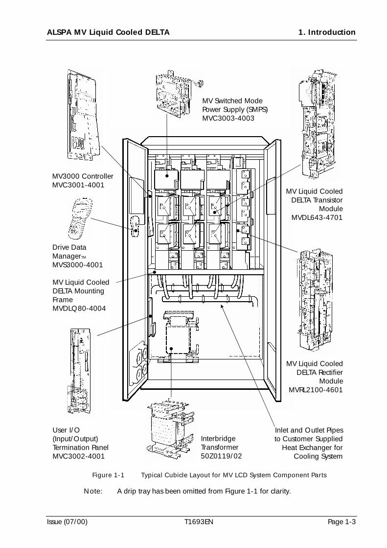
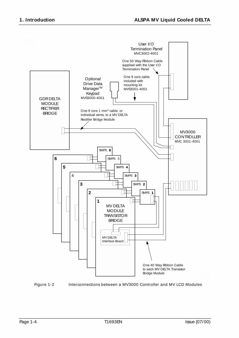
A typical MV3000 DELTA modular system is shown at Figure 1-1. Interconnectionsbetween the MV3000 Controller and system components are shown at Figure 1-2.
The MV3000 Controller is capable of driving up to six MV LCD transistor bridgemodules and two rectifier modules. The controller reads information from eachconnected module to check that the system configuration is consistent and toautomatically configure itself to the appropriate current rating.
Various configurations of voltage and current rating are achieved by software controlat initialisation.
1.3.2 Overview of MV LCD Drive System
The MV LCD system, which can be used to either control a motor or generate suppliesfrom an external source, comprises one or more liquid cooled modules and a MV3000controller. Application requirements determine the configuration of the modules, asdescribed in this section.
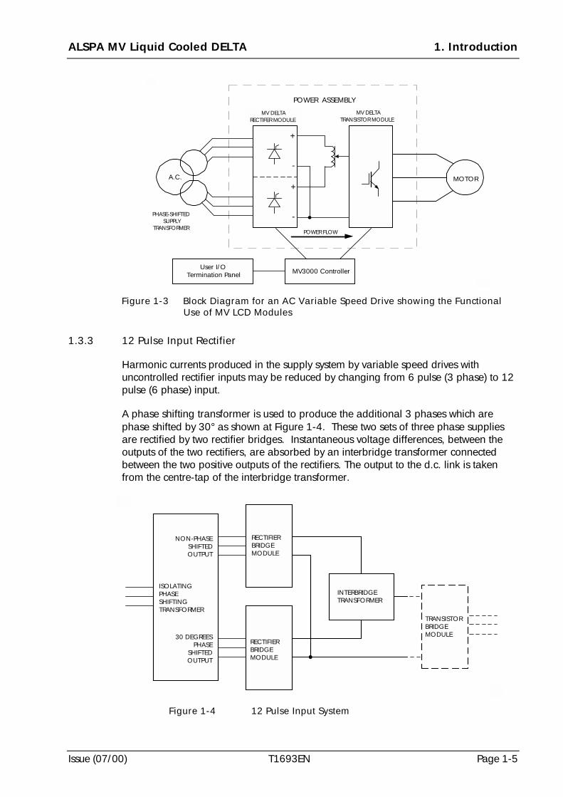
Figure 1-3 shows a simple a.c. variable speed drive which uses a MV3000 Controllerto control a power assembly. The power assembly has two major blocks. There is anetwork bridge (the Rectifier Module) that converts the a.c. supply to d.c. and amachine bridge (the Transistor Module) that chops up (inverts) this d.c. into a variablefrequency, variable voltage output. These power blocks are constructed using MV LCDmodules.
The network bridge may consist of an uncontrolled rectifier, a thyristor convertor, asinusoidally controlled transistor bridge or any source of d.c. that is within the limitsdefined at Section 2 - SPECIFICATION. The uncontrolled rectifier network bridge is a12 pulse bridge.
The machine bridge is a controlled transistor bridge.
ALSPA MV Liquid Cooled DELTA 1. Introduction
Issue (07/00) T1693EN Page 1-3
Note: A drip tray has been omitted from Figure 1-1 for clarity.
InterbridgeTransformer50Z0119/02
User I/O(Input/Output)Termination PanelMVC3002-4001
MV Liquid CooledDELTA Rectifier
ModuleMVRL2100-4601
MV Liquid CooledDELTA Transistor
ModuleMVDL643-4701
MV Liquid CooledDELTA MountingFrameMVDLQ80-4004
Inlet and Outlet Pipesto Customer Supplied
Heat Exchanger forCooling System
MV Switched ModePower Supply (SMPS)MVC3003-4003
MV3000 ControllerMVC3001-4001
Drive DataManagerMVS3000-4001
TM
Figure 1-1 Typical Cubicle Layout for MV LCD System Component Parts
1. Introduction ALSPA MV Liquid Cooled DELTA
Page 1-4 T1693EN Issue (07/00)
MV3000CONTROLLERMVC 3001-4001
GDR DELTAMODULERECTIFIERBRIDGE
OptionalDrive DataManagerTM
KeypadMVS3000-4001
User I/OTermination Panel
MVC3002-4001
One 50 Way Ribbon Cablesupplied with the User I/OTermination Panel
One 9 core 1 mm2 cable, orindividual wires, to a MV DELTARectifier Bridge Module
SMPS 6666
SMPS 5
SMPS 4444
SMPS 3333
SMPS 2222
SMPS 1111
6666
5555
4
3333
2222
1111MV DELTAMODULE
TRANSISTORBRIDGE
MV DELTAInterface Board
One 40 Way Ribbon Cableto each MV DELTA TransistorBridge Module
One 9 core cableincluded withmounting kitMVS3001-4001
Figure 1-2 Interconnections between a MV3000 Controller and MV LCD Modules
ALSPA MV Liquid Cooled DELTA 1. Introduction
Issue (07/00) T1693EN Page 1-5
1.3.3 12 Pulse Input Rectifier
Harmonic currents produced in the supply system by variable speed drives withuncontrolled rectifier inputs may be reduced by changing from 6 pulse (3 phase) to 12pulse (6 phase) input.
A phase shifting transformer is used to produce the additional 3 phases which arephase shifted by 30° as shown at Figure 1-4. These two sets of three phase suppliesare rectified by two rectifier bridges. Instantaneous voltage differences, between theoutputs of the two rectifiers, are absorbed by an interbridge transformer connectedbetween the two positive outputs of the rectifiers. The output to the d.c. link is takenfrom the centre-tap of the interbridge transformer.
PHASE-SHIFTEDSUPPLY
TRANSFORMER
MV DELTARECTIFER MODULE
POWER ASSEMBLY
MV DELTATRANSISTOR MODULE
POWER FLOW
MOTOR
MV3000 ControllerUser I/O
Termination Panel
A.C.
+
-
-
+
Figure 1-3 Block Diagram for an AC Variable Speed Drive showing the FunctionalUse of MV LCD Modules
ISOLATINGPHASESHIFTINGTRANSFORMER
NON-PHASESHIFTEDOUTPUT
30 DEGREESPHASE
SHIFTEDOUTPUT
RECTIFIERBRIDGEMODULE
RECTIFIERBRIDGEMODULE
INTERBRIDGETRANSFORMER
TRANSISTORBRIDGEMODULE
Figure 1-4 12 Pulse Input System
1. Introduction ALSPA MV Liquid Cooled DELTA
Page 1-6 T1693EN Issue (07/00)
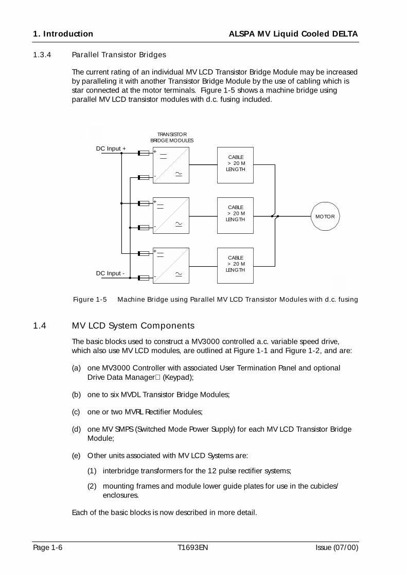
1.3.4 Parallel Transistor Bridges
The current rating of an individual MV LCD Transistor Bridge Module may be increasedby paralleling it with another Transistor Bridge Module by the use of cabling which isstar connected at the motor terminals. Figure 1-5 shows a machine bridge usingparallel MV LCD transistor modules with d.c. fusing included.
1.4 MV LCD System Components
The basic blocks used to construct a MV3000 controlled a.c. variable speed drive,which also use MV LCD modules, are outlined at Figure 1-1 and Figure 1-2, and are:
(a) one MV3000 Controller with associated User Termination Panel and optionalDrive Data Manager (Keypad);
(b) one to six MVDL Transistor Bridge Modules;
(c) one or two MVRL Rectifier Modules;
(d) one MV SMPS (Switched Mode Power Supply) for each MV LCD Transistor BridgeModule;
(e) Other units associated with MV LCD Systems are:
(1) interbridge transformers for the 12 pulse rectifier systems;
(2) mounting frames and module lower guide plates for use in the cubicles/enclosures.
Each of the basic blocks is now described in more detail.
TRANSISTORBRIDGE MODULES
DC Input +
DC Input -
MOTOR
CABLE > 20 MLENGTH
CABLE > 20 MLENGTH
CABLE > 20 MLENGTH
+
-
-
-
+
+
Figure 1-5 Machine Bridge using Parallel MV LCD Transistor Modules with d.c. fusing
ALSPA MV Liquid Cooled DELTA 1. Introduction
Issue (07/00) T1693EN Page 1-7
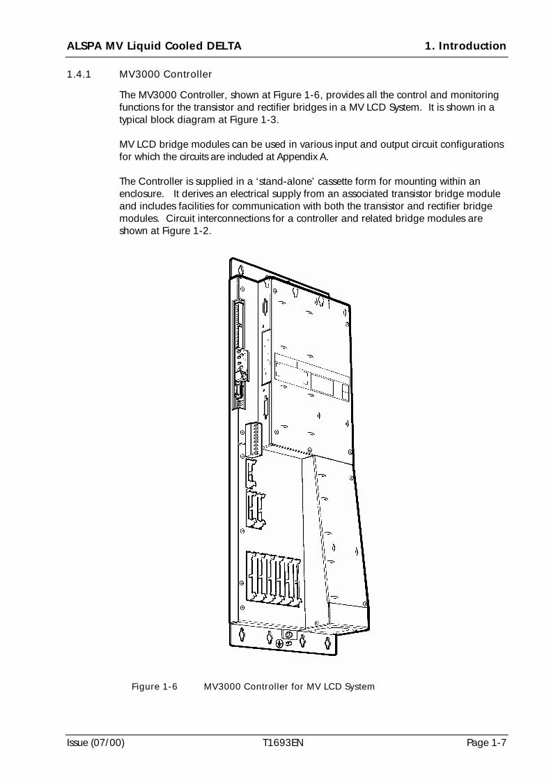
1.4.1 MV3000 Controller
The MV3000 Controller, shown at Figure 1-6, provides all the control and monitoringfunctions for the transistor and rectifier bridges in a MV LCD System. It is shown in atypical block diagram at Figure 1-3.
MV LCD bridge modules can be used in various input and output circuit configurationsfor which the circuits are included at Appendix A.
The Controller is supplied in a ‘stand-alone’ cassette form for mounting within anenclosure. It derives an electrical supply from an associated transistor bridge moduleand includes facilities for communication with both the transistor and rectifier bridgemodules. Circuit interconnections for a controller and related bridge modules areshown at Figure 1-2.
Figure 1-6 MV3000 Controller for MV LCD System
1. Introduction ALSPA MV Liquid Cooled DELTA
Page 1-8 T1693EN Issue (07/00)
1.4.2 MV3000 User Input/Output (I/O) Termination Panel
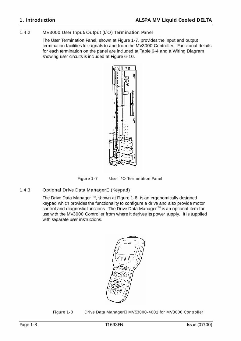
The User Termination Panel, shown at Figure 1-7, provides the input and outputtermination facilities for signals to and from the MV3000 Controller. Functional detailsfor each termination on the panel are included at Table 6-4 and a Wiring Diagramshowing user circuits is included at Figure 6-10.
1.4.3 Optional Drive Data Manager (Keypad)
The Drive Data Manager TM, shown at Figure 1-8, is an ergonomically designedkeypad which provides the functionality to configure a drive and also provide motorcontrol and diagnostic functions. The Drive Data Manager TM is an optional item foruse with the MV3000 Controller from where it derives its power supply. It is suppliedwith separate user instructions.
Figure 1-7 User I/O Termination Panel
Figure 1-8 Drive Data Manager MVS3000-4001 for MV3000 Controller
ALSPA MV Liquid Cooled DELTA 1. Introduction
Issue (07/00) T1693EN Page 1-9
1.5 MV LCD Modules
There are two types of MV LCD Modules, the Rectifier Bridge Module and the TransistorBridge Module. These modules are mounted in one of two types of mounting framefor assembly into either an ALSTOM Q80 Cubicle or a Rittal PS4000 Series Cubicle.
A typical cubicle layout for a MV LCD system is shown at Figure 1-1.
1.5.1 Rectifier Bridge Module
1.5.1.1 Introduction
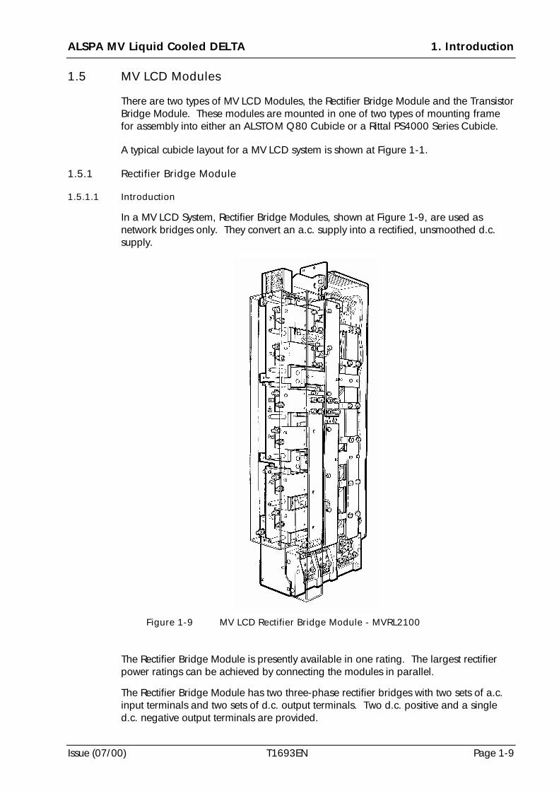
In a MV LCD System, Rectifier Bridge Modules, shown at Figure 1-9, are used asnetwork bridges only. They convert an a.c. supply into a rectified, unsmoothed d.c.supply.
The Rectifier Bridge Module is presently available in one rating. The largest rectifierpower ratings can be achieved by connecting the modules in parallel.
The Rectifier Bridge Module has two three-phase rectifier bridges with two sets of a.c.input terminals and two sets of d.c. output terminals. Two d.c. positive and a singled.c. negative output terminals are provided.
Figure 1-9 MV LCD Rectifier Bridge Module - MVRL2100
1. Introduction ALSPA MV Liquid Cooled DELTA
Page 1-10 T1693EN Issue (07/00)
The Rectifier Bridge Module may be operated as a 12-pulse network bridge. Thisconfiguration is achieved by connecting the d.c. positive outputs together through aninterbridge transformer, one a.c. input being phase-shifted in relation to the other bythe external supply transformer.
The rectifier modules fit in a standard MV LCD module mounting system - see 1.7.
1.5.1.2 Features
• A Rectifier Bridge Module includes a circuit which is capable of pre-charging theTransistor Bridge Modules. This circuit charges the d.c. link capacitors of thetransistor bridge via current limiting resistors in the rectifier modules.
• Modules fit in the standard MV LCD mounting frames.
• Metal oxide varistors are included to absorb surge energy from the mains. Supplyimpedance is necessary for this to function correctly. See 1.6 for information onreactors.
• Protection against d.c. link short circuits by the use of recommendedsemiconductor fuses.
• Modules carry thermostat and thermistor protection so when they are connected tothe controller, the module is protected against overtemperature.
1.5.1.3 Variations
• The Rectifier Bridge Module is only available in a current rating of 2100 A (d.c.output current).
• Higher current versions are possible by paralleling the modules through reactors.As the modules will not carry equal current, some derating of the output current isnecessary.
• The Rectifier Bridge Module is available for a voltage of 575 - 690 V a.c.
1.5.1.4 Interface
• Signals between the controller and the rectifier bridge module are by discretewires, which are between 'pluggable' terminal blocks.
• The MVRL2100 power connections are designed for cable connection to studterminals.
1.5.1.5 External Requirements
• For parallel operation of these modules, external sharing reactors must be fitted.
• For 12 pulse operation the two supplies must be phase shifted by 30° to eachother and of balanced voltage. The output must be through an interbridgetransformer.
• Protection of the main input rectifier devices is by the addition of externalsemiconductor fuses - for recommended fuses see Section 2 - SPECIFICATION.
ALSPA MV Liquid Cooled DELTA 1. Introduction
Issue (07/00) T1693EN Page 1-11
• The a.c. terminals on the modules designed for cable connection are not suitableto support the weight of any attached cables. These cables/busbars must haveadditional mechanical support.
• The output from all of the Rectifier Bridge Modules must be through an interbridgetransformer.
1.5.2 Transistor Bridge Module
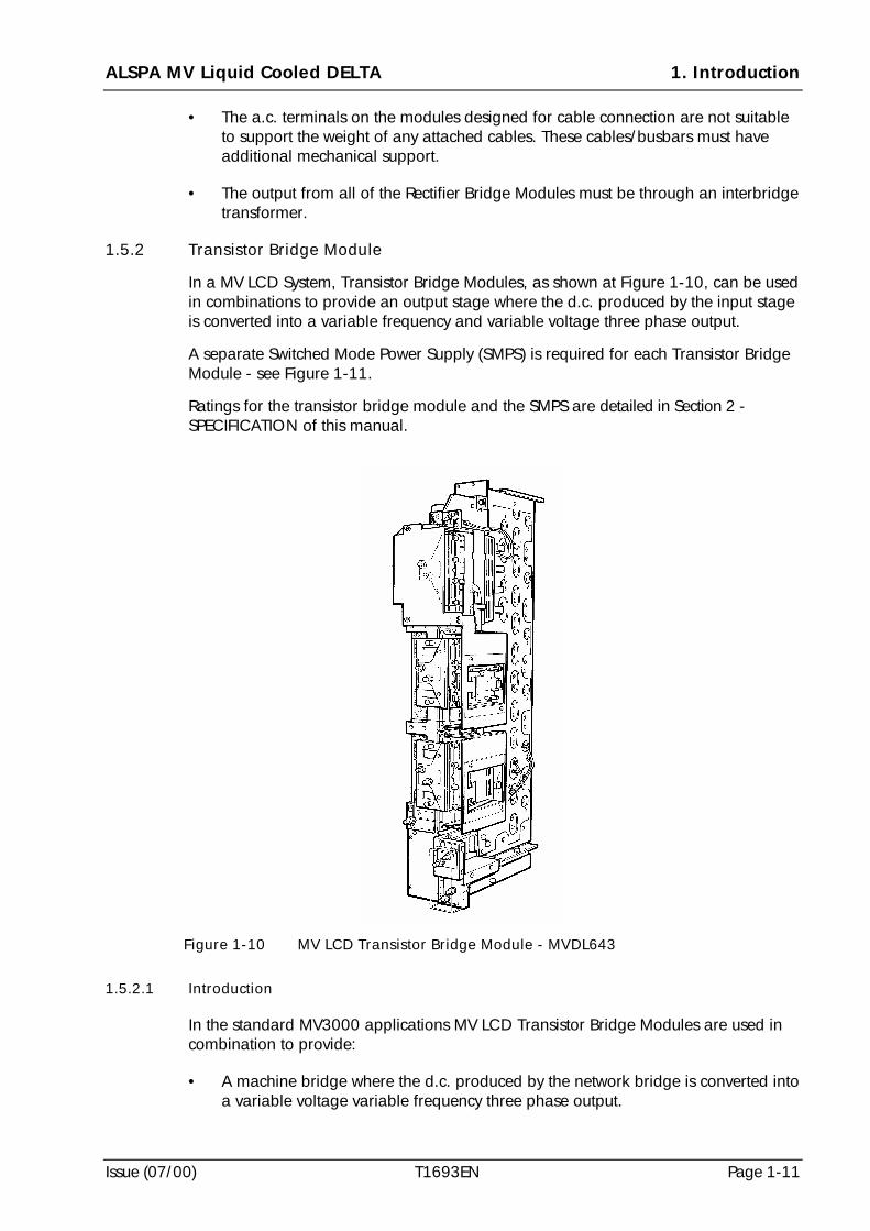
In a MV LCD System, Transistor Bridge Modules, as shown at Figure 1-10, can be usedin combinations to provide an output stage where the d.c. produced by the input stageis converted into a variable frequency and variable voltage three phase output.
A separate Switched Mode Power Supply (SMPS) is required for each Transistor BridgeModule - see Figure 1-11.
Ratings for the transistor bridge module and the SMPS are detailed in Section 2 -SPECIFICATION of this manual.
1.5.2.1 Introduction
In the standard MV3000 applications MV LCD Transistor Bridge Modules are used incombination to provide:
• A machine bridge where the d.c. produced by the network bridge is converted intoa variable voltage variable frequency three phase output.
Figure 1-10 MV LCD Transistor Bridge Module - MVDL643
1. Introduction ALSPA MV Liquid Cooled DELTA
Page 1-12 T1693EN Issue (07/00)
1.5.2.2 Features
• MV LCD Transistor Bridge Modules use the latest insulated-gate bipolar transistors(IGBT) in Integrated Intelligent Power Packs (IIP) to provide low distortion output.
• DC smoothing capacitors that provide filtering for the drive d.c. link in addition tolocal energy storage for transistor switching.
• Output protection against short circuits.
• Modules fit in standard MV LCD rack system.
• Auxiliary d.c. link connection plug for voltage monitoring and connection to SwitchMode Power Supply (SMPS). The appropriate MV SMPS is mounted on theTransistor Bridge Module.
• Each module carries thermistor protection. When connected to the MV3000controller the module is protected against overtemperature.
• Each module includes fan monitoring to check the state of the cooling fans whichare used to cool the d.c. link capacitors on the module.
1.5.2.3 Variations
• The Transistor Bridge Module is only available in a current rating of 643 A at 690 V.
• This version is suitable for the Network and machine bridges on MV3000 drivesand as the Network or Machine power bridges in common d.c. link applications.
1.5.2.4 Interface
• Signals between the controller and Transistor Bridge Module are by a single40 way ribbon cable per module. This cable also carries the supplies for theelectronics in the controller.
• Power connections are stud terminals for the a.c. and d.c. connections.
• Auxiliary d.c. link connections.
1.5.2.5 External Requirements
• The Transistor Bridge Module contains smoothing capacitors which when used inboth Network and machine bridge applications must be 'pre-charged'. Thesemodules do not carry pre-charge circuits. Pre-charge is either via a RectifierBridge Module (MVRL2100-4601) or external circuitry. Refer to ALSTOM forrecommended pre-charge rates.
• The d.c. supply to the transistor module must be within appropriate voltage,current and ripple limits and must be 'pre-charged'.
• These liquid cooled modules must be cooled by an externally derived coolingsystem.
• When Transistor Bridge Modules are used as network bridges it is recommendedthat semiconductor fuses are fitted on the a.c. supply on a per module basis.
ALSPA MV Liquid Cooled DELTA 1. Introduction
Issue (07/00) T1693EN Page 1-13
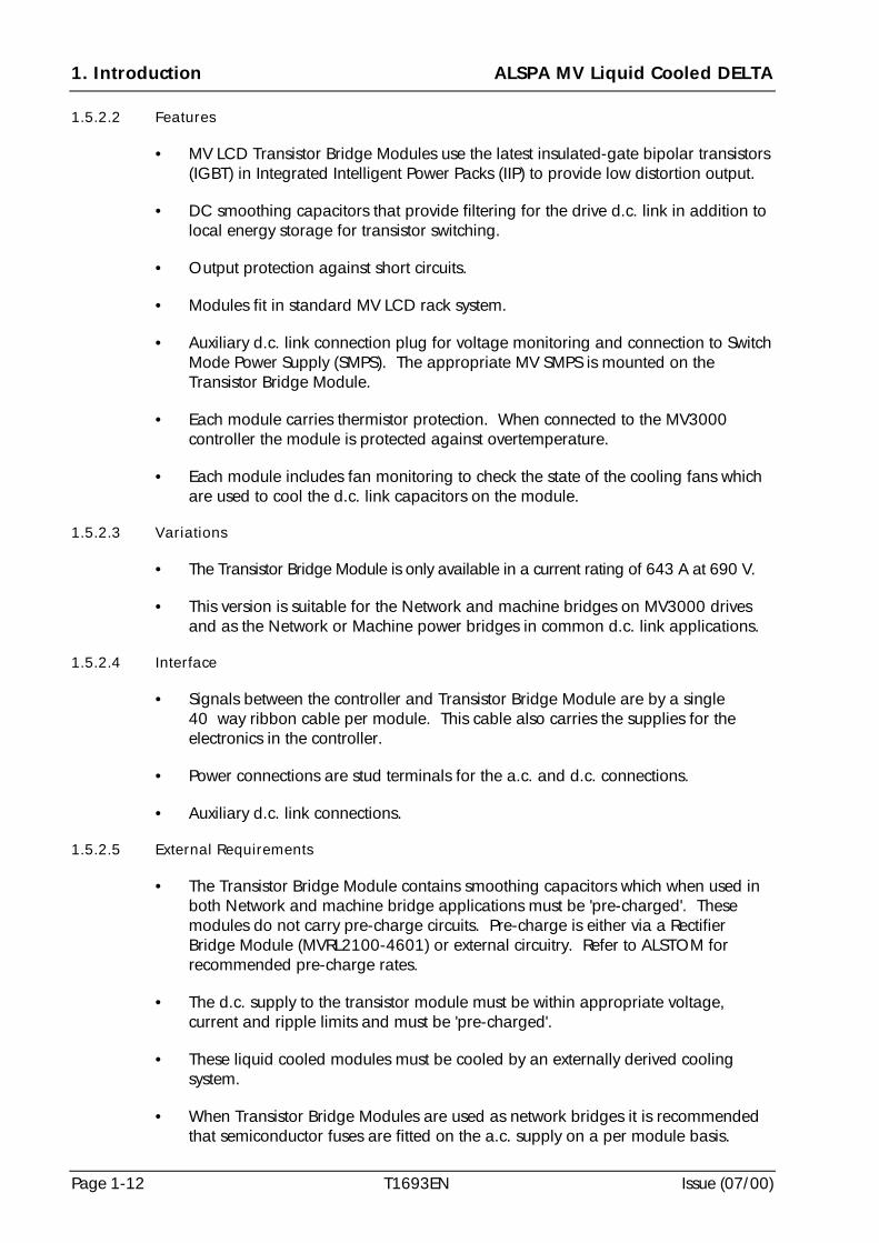
1.5.3 MV Switched Mode Power Supply (SMPS)
The MV SMPS, shown at Figure 1-11, is mounted on a Transistor Bridge Module. Itprovides the electronic supplies for the Transistor Bridge Module and the MV3000Controller. The SMPS derives a supply from the drive d.c. link; the low voltageelectronics are maintained during a temporary loss of supply.
There is initially only one type of SMPS. The specification is included at Section 2 -SPECIFICATION.
1.6 Reactors, Inductors and Transformers
1.6.1 General Description
A variety of reactors, inductors and transformers will be available for use in conjunctionwith the MV LCD power modules. Different functions which these optional andmandatory components may be used for are now described.
Where a drive is supplied by an individual transformer of approximately the samerating as the drive then input line reactors are not required. However, account shouldbe taken of the effective reactance requirements within the specification for theassociated supply transformer for the drive.
It is recommended that input line reactors are fitted in the following circumstances:
(a) if there is primary switching of a transformer e.g. 13.8 kV circuit breakers, on lineprimary tap changing etc. and the transformer is large (i.e. greater than 17 MVAfault level);
(b) if there is power factor correction equipment on the same supply as the drive;
(c) if there is a high risk of a short circuit on the secondary of a transformer caused byother equipment with separate fuse protection;
(d) where semi-conductor fuses will not protect the input rectifiers without additionalline impedance - see fuse information at Section 2 - SPECIFICATION.
Figure 1-11 MV SMPS - MVC3003
1. Introduction ALSPA MV Liquid Cooled DELTA
Page 1-14 T1693EN Issue (07/00)
1.6.2 Sharing Reactance
To allow even load sharing between Transistor Bridge Modules which are connected inparallel it is always necessary to fit additional reactance in the three-phase connectionof each parallel module.
1.6.2.1 Reactors for Network Bridges
For network bridges on MV3000 applications multi-filar input reactors arerecommended.
1.6.2.2 Reactors for Machine Bridges
For machine bridges sharing reactance can be obtained by use of separate motorcables of 20 m minimum length.
1.6.3 Interbridge Transformer for 12 Pulse Rectifier Systems
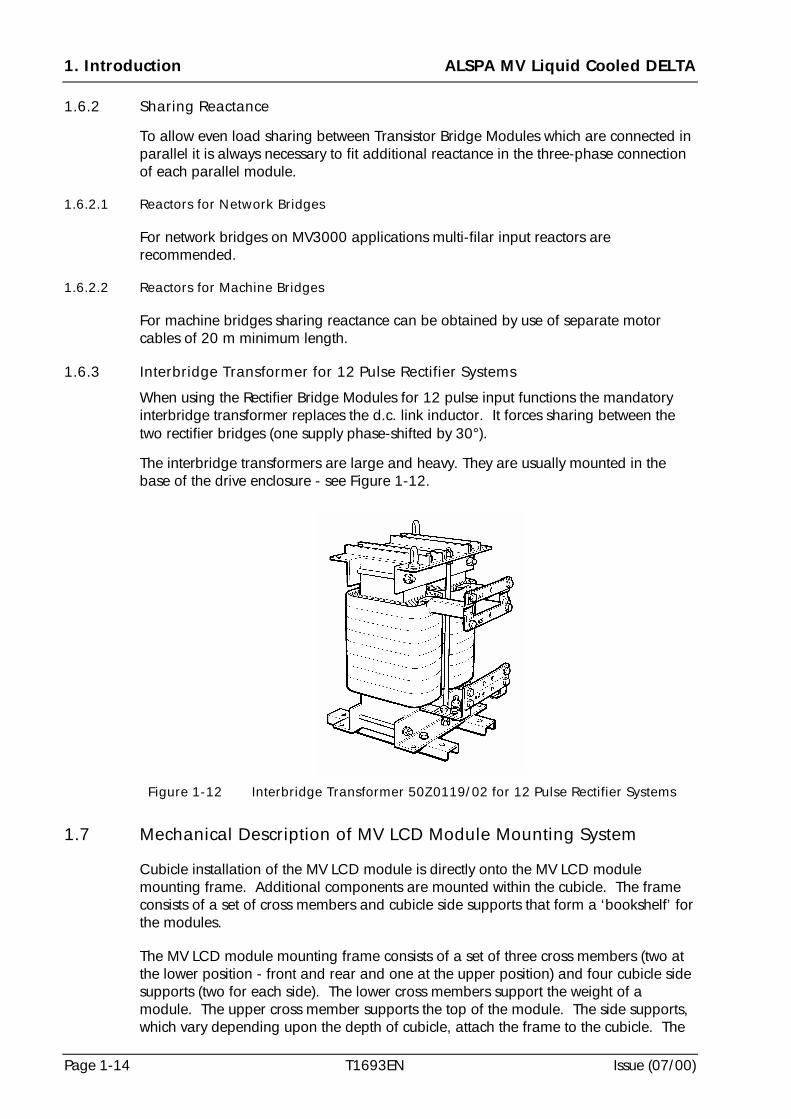
When using the Rectifier Bridge Modules for 12 pulse input functions the mandatoryinterbridge transformer replaces the d.c. link inductor. It forces sharing between thetwo rectifier bridges (one supply phase-shifted by 30°).
The interbridge transformers are large and heavy. They are usually mounted in thebase of the drive enclosure - see Figure 1-12.
1.7 Mechanical Description of MV LCD Module Mounting System
Cubicle installation of the MV LCD module is directly onto the MV LCD modulemounting frame. Additional components are mounted within the cubicle. The frameconsists of a set of cross members and cubicle side supports that form a ‘bookshelf’ forthe modules.
The MV LCD module mounting frame consists of a set of three cross members (two atthe lower position - front and rear and one at the upper position) and four cubicle sidesupports (two for each side). The lower cross members support the weight of amodule. The upper cross member supports the top of the module. The side supports,which vary depending upon the depth of cubicle, attach the frame to the cubicle. The
Figure 1-12 Interbridge Transformer 50Z0119/02 for 12 Pulse Rectifier Systems
ALSPA MV Liquid Cooled DELTA 1. Introduction
Issue (07/00) T1693EN Page 1-15
spacing between the upper and lower cross members is fixed by the height of themodule. The overall position of the mounting frame is dependent on cubiclerequirements.
The MV LCD modules are mounted between the upper and lower cross members bysimple guides, two located on the lower guide plate and two on the upper crossmember. The module slides between these guides and is then bolted to the crossmembers. When extracting a module it slides as far as the stop screw and then has tobe lifted over this screw before it may be completely removed. The lower guide plate isdirectly attached to the cross members.
The installation of additional MV LCD modules is a step, by 250 mm (9.84 in), andrepeat of the assembly up to the width of the cross members.
1.7.1 MV LCD Module Mounting Kit
1.7.1.1 Introduction
The MV LCD module mounting kit is a framework of cross members and brackets,which when installed in a cubicle, provide the support and fixings for the modules. It issuitable for installation into standard ALSTOM Q80 cubicles and Rittal PS4000 seriescubicles - refer to Section 5 - MECHANICAL INSTALLATION for details.
1.7.1.2 Variations
• The standard kits are based on 600 mm (23.6 in) and 800 mm (31.5 in) deepcubicles. For each of these depths of cubicle there are four cross member widthsavailable, 600 mm (23.6 in), 800 mm (31.5 in), 1000 mm (39.4 in) and1200 mm (47.2 in).
• The 600 mm (23.6 in) and 800 mm (31.5 in) wide cross members will support upto two MV LCD modules. The 800 mm (31.5 in) wide kit is not frequently used, asit will only hold two modules.
• The 1000 mm (39.4 in) wide cross members will support up to three MV LCDmodules.
• The 1200 mm (47.2 in) wide cross members will support up to four MV LCDmodules.
1.7.1.3 Interface and External Requirements
• The mounting frame bolts directly into the ALSTOM Q80 and Rittal PS4000 seriescubicles but requires a different side mounting kit for each type of cubicle.
• The mounting frame kits for Q80 and PS4000 series cubicles are available indepths of 600 and 800 mm and widths of 600, 800, 1000 and 1200 mm. Fordetails see 2.12. For mounting in other types of enclosure see 5.4.
1. Introduction ALSPA MV Liquid Cooled DELTA
Page 1-16 T1693EN Issue (07/00)
1.8 Cooling
1.8.1 Cooling of a MV LCD Module
Each MV LCD module is cooled principally by a liquid coolant which is pumpedthrough it. Heat generated within a module is carried away by the coolant flow; referto 1.8.3 for full details and Section 3 - COOLING SYSTEM DESIGN.
1.8.2 Cubicle Cooling Air
In addition to the liquid cooling system there is also a requirement for a clean coolingair flow through any cubicle/enclosure in which a MV LCD module is housed. This airflow should ensure that the modules and associated electronic circuits are operating ina clean, dust-free air which is free from corrosive vapours and cooled for operationwithin the temperature specification. The air flow is normally determined for eachapplication but would typically include an air intake on a cubicle door with fanassistance and filtering as required. Factors to be considered when determining theamount of cooling air to be supplied to a cubicle and whether it should be filtered are:
(a) the amount of heat which is dissipated from the MV LCD module(s) into thecubicle - see Section 2 - SPECIFICATION for guidance;
(b) the amount of heat which is dissipated from the electronic and electricalcircuits/components associated with the MV LCD module(s) - see Section 2 -SPECIFICATION for guidance;
(c) the internal and external ambient temperatures;
(d) the method of obtaining and extracting the cooling air;
(e) the type and amount of contamination in the cooling air and the need for anyfiltering (e.g. is the contamination conductive or corrosive?).
Note: In extreme environments the use of dual circuit heat exchangers isrecommended.
1.8.3 MV LCD Module Cooling System
1.8.3.1 Introduction
The MV LCD product range is a high power rated industrial drive which uses a water-ethylene glycol coolant system to move heat away from the power electronics to aposition where it can be more effectively dissipated into the environment. Thisdissipation is normally done with a liquid-to-air heat exchanger.
A fully integrated cooling system should comprise the following items:
(a) a liquid-to-air heat exchanger:
(b) a force ventilation fan;
(c) a pump;
(d) a header tank;
ALSPA MV Liquid Cooled DELTA 1. Introduction
Issue (07/00) T1693EN Page 1-17
(e) a strainer;
(f) ball valves;
(g) inlet and outlet manifolds;
(h) instrumentation for coolant conditions e.g. measurement of temperature and flowrate - refer to 3.2 for more details.
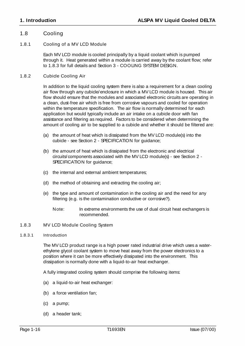
The cooling system is used for all of the MV LCD modules described in this technicalmanual. Each module includes a precision machined casting with a cooling ductthrough which the liquid coolant is pumped; normally a water-ethylene glycol mixture.Additional components are required to complete the cooling system. A typical liquid-to-air cooling system for a multiple MV LCD module configuration is included atFigure 1-13.
1.8.3.2 Features
• The MV LCD module has ‘spring loaded’ couplings with ‘auto shut-off’ valvesfitted to enable cooling pipes to be easily connected to, or released from it,without excessive coolant loss.
• Vent valves are included on the MV LCD module.
• The Cooling System can be designed to suit any combination of MV LCD modules.
1.8.3.3 Variations
• There are variations in piping to the MV LCD modules, depending on how manymodules are installed in each cubicle/enclosure.
• Details for mechanical installation of all the piping and connectors at the LiquidCooled DELTA modules are included at Section 5 - MECHANICAL INSTALLATION.
• The external cooling system should be designed to suit user requirements.
FAN
HEATEXCHANGER
PUMP
A.C. SUPPLY
STRAINER INLET MANIFOLD
BALLVALVE
BALLVALVE
LCD
LCD
LCD
LCD
OUTLET MANIFOLDHEADER
TANK
Figure 1-13 Simplified Diagram of a Cooling System for Four MV LCD Modules
1. Introduction ALSPA MV Liquid Cooled DELTA
Page 1-18 T1693EN Issue (07/00)
1.8.3.4 Interface
• Specification for the types of piping and connections are included at Section 3 -COOLING SYSTEM DESIGN.
• Details for the routing of piping and connections into and within acubicle/enclosure are detailed at Section 5 - MECHANICAL INSTALLATION.
1.8.3.5 External Requirements
• Design guidance for the external cooling system is given at Section 3 - COOLINGSYSTEM DESIGN.
• Additional components, to be supplied and installed by the system integrator, arerequired to complete a cooling system e.g. items listed at 1.8.3.1 and associatedplumbing and application dependent control, protection and instrumentation.
• The additional components may be installed separately from the cubicle whichhouses the MV LCD modules.
1.8.4 Drip Tray
A drip tray should be used to collect any condensate from the MV LCD module casting. The method of draining condensate from the tray should be specified by the systemintegrator. Refer to ALSTOM if advice is required.
1.9 Compatibility between ALSTOM GD and MV DELTA Systems
Some guidance is necessary if MV LCD systems are being used for applications whereGD Liquid Cooled DELTA systems are already in use - refer to ALSTOM for adviceabout compatibility.
The items which cannot be interchanged are:
(a) MV3000 Controller;
(b) Drive Data Manager ;
(c) Rectifier Bridge Modules;
(d) Transistor Bridge Modules;
(e) Switched Mode Power Supplies;
(f) User I/O Termination Panel;
(g) All ribbon cables;
(h) Different parts in the module mounting frames e.g. the lower guide rails.
ALSPA MV Liquid Cooled DELTA 2. Specification
Issue (07/00) T1693EN Page 2-1
2. Specification
2.1 Introduction
The specifications provided in this section are for the individual MV Liquid CooledDELTA (MV LCD) power components. These components are the transistor andrectifier bridge modules and the module cooling system, the MV3000 Controller, theSwitched Mode Power Supply (SMPS), the User I/O Termination Panel, associatedreactors and transformers and the module mounting frames (for use in cubicles). Consideration should be given to the rating of individual components when they areincluded in a system as derating for parallel applications may apply.
2.2 ALSPA MV LCD Components (General Environment)
All ALSPA MV LCD components are designed to comply with the commonspecifications at Table 2-1 and Table 2-3 unless otherwise detailed in the individualcomponent specification. Drive performance data for a MV3000 based Liquid CooledDELTA drive is included at Table 2-2.
Table 2-1 Electrical Specification
Function Specification
ELECTRICAL SUPPLY
Network Type TN or TT (i.e. earthed/grounded neutral).
Can also be connected to IT network (i.e. isolated neutral) if IT networkseparated from public mains supply by an isolating transformer.
Voltage Range 575 V - 690 V (600 V nominal)
Voltage Variation
(on voltage range)
±10% long term, ±15% for 0.5 to 30 cycles with loss of performancebut no trip
Voltage Unbalance Negative sequence voltage not to exceed 3%
Frequency (optimised) 50 Hz, 60 Hz
Operational Frequency Range 45 Hz to 63 Hz. With frequencies outside the optimised values, extrad.c. link ripple may be apparent and may impair motor controlperformance.
SWITCHING FREQUENCY
Default Setting 1.25 kHz, 2.5 kHz, 5 kHz and 7.5 kHz for all drives (programmableby P99.02).
OUTPUT
Overload Current 50% or 10% for one minute, as selected.
INSULATION
Standards UL 840, CSA C22-2 No. 0.2, EN 50178:
TN or TT network : Overvoltage Category III
IT network : Overvoltage Category II
For full compliance with UL 508C, transient suppressers complyingwith UL 1449 must be fitted external to the drive.
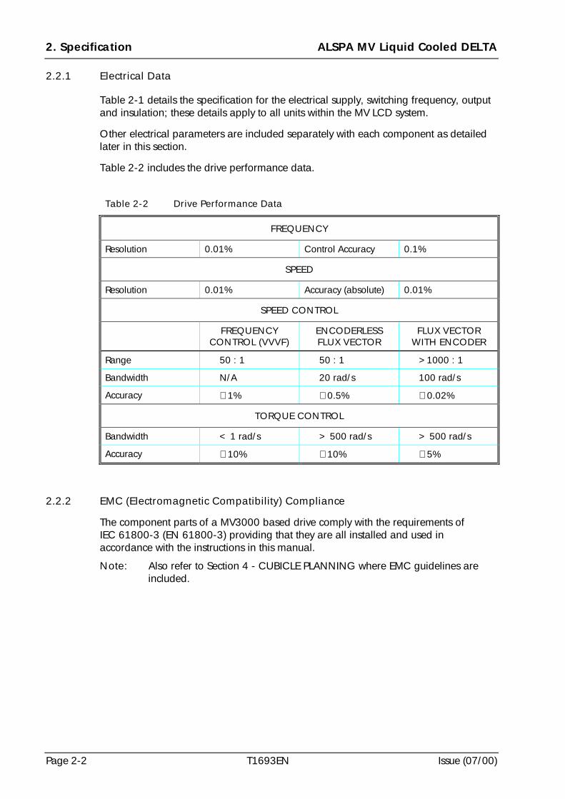
2. Specification ALSPA MV Liquid Cooled DELTA
Page 2-2 T1693EN Issue (07/00)
2.2.1 Electrical Data
Table 2-1 details the specification for the electrical supply, switching frequency, outputand insulation; these details apply to all units within the MV LCD system.
Other electrical parameters are included separately with each component as detailedlater in this section.
Table 2-2 includes the drive performance data.
Table 2-2 Drive Performance Data
FREQUENCY
Resolution 0.01% Control Accuracy 0.1%
SPEED
Resolution 0.01% Accuracy (absolute) 0.01%
SPEED CONTROL
FREQUENCYCONTROL (VVVF)
ENCODERLESSFLUX VECTOR
FLUX VECTORWITH ENCODER
Range 50 : 1 50 : 1 >1000 : 1
Bandwidth N/A 20 rad/s 100 rad/s
Accuracy ≅ 1% ≅ 0.5% ≅ 0.02%
TORQUE CONTROL
Bandwidth < 1 rad/s > 500 rad/s > 500 rad/s
Accuracy ≅ 10% ≅ 10% ≅ 5%
2.2.2 EMC (Electromagnetic Compatibility) Compliance
The component parts of a MV3000 based drive comply with the requirements ofIEC 61800-3 (EN 61800-3) providing that they are all installed and used inaccordance with the instructions in this manual.
Note: Also refer to Section 4 - CUBICLE PLANNING where EMC guidelines areincluded.
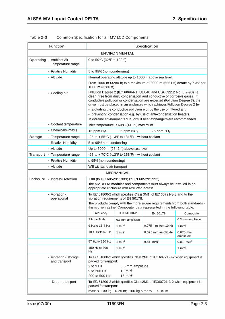
ALSPA MV Liquid Cooled DELTA 2. Specification
Issue (07/00) T1693EN Page 2-3
Table 2-3 Common Specification for all MV LCD Components
Function Specification
ENVIRONMENTAL
Operating - Ambient AirTemperature range
0 to 50°C (32°F to 122°F)
- Relative Humidity 5 to 95% (non-condensing)
- Altitude Normal operating altitude up to 1000m above sea level.
From 1000 m (3280 ft) to a maximum of 2000 m (6551 ft) derate by 7.3% per1000 m (3280 ft).
- Cooling air Pollution Degree 2 (IEC 60664-1, UL 840 and CSA C22.2 No. 0.2-93) i.e.clean, free from dust, condensation and conductive or corrosive gases. Ifconductive pollution or condensation are expected (Pollution Degree 3), thedrive must be placed in an enclosure which achieves Pollution Degree 2 by:- excluding the conductive pollution e.g. by the use of filtered air;- preventing condensation e.g. by use of anti-condensation heaters.In extreme environments dual circuit heat exchangers are recommended.
- Coolant temperature Inlet temperature is 60°C (140°F) maximum
- Chemicals (max.) 15 ppm H2S 25 ppm NO2 25 ppm SO2
Storage - Temperature range -25 to +55°C (-13°F to 131°F) – without coolant
- Relative Humidity 5 to 95% non-condensing
- Altitude Up to 3000 m (9842 ft) above sea level
Transport - Temperature range -25 to +70°C (-13°F to 158°F) – without coolant
- Relative Humidity ≤ 95% (non-condensing)
- Altitude Will withstand air transport
MECHANICAL
Enclosure - Ingress Protection IP00 (to IEC 60529: 1989; BS EN 60529:1992)The MV DELTA modules and components must always be installed in anappropriate enclosure with restricted access.
- Vibration -operational
To IEC 61800-2 which specifies ‘Class 3M1’ of IEC 60721-3-3 and to thevibration requirements of EN 50178.The products comply with the more severe requirements from both standards -this is given as the ‘Composite’ data represented in the following table.
Frequency IEC 61800-2 EN 50178 Composite
2 Hz to 9 Hz 0.3 mm amplitude 0.3 mm amplitude
9 Hz to 18.4 Hz 1 m/s2 0.075 mm from 10 Hz 1 m/s2
18.4 Hz to 57 Hz 1 m/s2 0.075 mm amplitude 0.075 mmamplitude
57 Hz to 150 Hz 1 m/s2 9.81 m/s2 9.81 m/s2
150 Hz to 200Hz
1 m/s2 1 m/s2
- Vibration - storage and transport
To IEC 61800-2 which specifies Class 2M1 of IEC 60721-3-2 when equipment ispacked for transport:2 to 9 Hz 3.5 mm amplitude9 to 200 Hz 10 m/s2
200 to 500 Hz 15 m/s2
- Drop - transport To IEC 61800-2 which specifies Class 2M1 of IEC60721-3-2 when equipment ispacked for transport:mass < 100 kg 0.25 m; 100 kg ≤ mass 0.10 m
2. Specification ALSPA MV Liquid Cooled DELTA
Page 2-4 T1693EN Issue (07/00)
2.3 MV3000 Controller
2.3.1 Terminations
The terminations from the MV3000 Controller to other equipment in the MV LCDsystem are as follows:
(a) One 40 way ribbon cable to each Transistor Bridge Module - see Table 6-1;
(b) One 9 way connector for wiring* to the Rectifier Bridge Module.
Note: * Wiring should have a cross sectional area between limits of:Minimum 0.5 mm2 or 20 AWG (use a consolidating crimp)
Maximum 2.5 mm2 or 14 AWG
(c) One screened cable to an optional Drive Data Manager Keypad - see Table 6-3;
(d) One 50 Way ribbon cable to the User I/O Termination Panel - supplied with theUser I/O Termination Panel.
2.3.2 Weight
The MV3000 Controller weighs 4 kg (8.8 lb).
2.4 User I/O Termination Panel
The user connectors on the User I/O Termination Panel are suitable for 0.5 mm2 -2.5 mm2 (20 to 14 AWG) single core or flexible cable*. A consolidating crimp shouldbe used for the minimum size. Refer to Table 6-4 for a specification of each terminalfunction. A 50 way ribbon cable, supplied with the panel, connects to the controller.
Note: * UL/CSA Approval requires cable in the range No. 22 - 12 AWG.
2.5 MV3000 Drive Data ManagerTM (Keypad)
The specification for the Drive Data ManagerTM is included at the T1915 InstructionSheet which is supplied with it.
2.6 Rectifier Bridge Module
Unit covered: MVRL2100-4601.
2.6.1 Current Ratings
Overloads are for 60 seconds, 6 times per hour equally spaced.
All ratings assume standard drive configurations using interbridge transformers.
If two separate Rectifier Bridge Modules are paralleled derate the output current by10% to allow for current imbalance between the bridges.
To protect a Rectifier Bridge Module from d.c. link side short circuits it is recommendedthat a.c. supply semi-conductor fuses be fitted. The current rating of the Rectifier BridgeModule with the recommended fuses, from Le Carbone (Ferraz Shawmut), is given atTable 2-4.
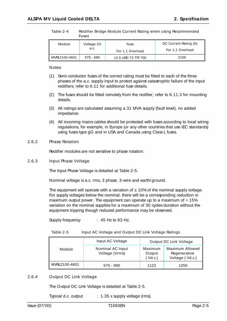
ALSPA MV Liquid Cooled DELTA 2. Specification
Issue (07/00) T1693EN Page 2-5
Table 2-4 Rectifier Bridge Module Current Rating when using RecommendedFuses
Module Voltage (V)a.c.
Fuse
For 1.1 Overload
DC Current Rating (A)
For 1.1 Overload
MVRL2100-4601 575 - 690 12.5 URD 73 TTF 700 2100
Notes:
(1) Semi-conductor fuses of the correct rating must be fitted to each of the threephases of the a.c. supply input to protect against catastrophic failure of the inputrectifiers; refer to 6.11 for additional fuse details.
(2) The fuses should be fitted remotely from the rectifier; refer to 6.11.3 for mountingdetails.
(3) All ratings are calculated assuming a 31 MVA supply (fault level), no addedimpedance.
(4) All incoming mains cables should be protected with fuses according to local wiringregulations, for example, in Europe (or any other countries that use IEC standards)using fuses type gG and in USA and Canada using Class L fuses.
2.6.2 Phase Rotation
Rectifier modules are not sensitive to phase rotation.
2.6.3 Input Phase Voltage
The Input Phase Voltage is detailed at Table 2-5.
Nominal voltage is a.c. rms, 3 phase, 3-wire and earth/ground.
The equipment will operate with a variation of ±10% of the nominal supply voltage.For supply voltages below the nominal, there will be a corresponding reduction inmaximum output power. The equipment can operate up to a maximum of +15%variation on the nominal supplies for a maximum of 30 cycles duration without theequipment tripping though reduced performance may be observed.
Supply frequency : 45 Hz to 63 Hz.
Table 2-5 Input AC Voltage and Output DC Link Voltage Ratings
Input AC Voltage Output DC Link Voltage
Module Nominal AC InputVoltage (Vrms)
MaximumOutput( Vd.c.)
Maximum AllowedRegenerative
Voltage ( Vd.c.)
MVRL2100-4601 575 - 690 1122 1250
2.6.4 Output DC Link Voltage
The Output DC Link Voltage is detailed at Table 2-5.
Typical d.c. output : 1.35 x supply voltage (rms).
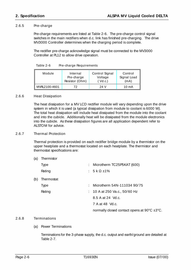
2. Specification ALSPA MV Liquid Cooled DELTA
Page 2-6 T1693EN Issue (07/00)
2.6.5 Pre-charge
Pre-charge requirements are listed at Table 2-6. The pre-charge control signalswitches in the main rectifiers when d.c. link has finished pre-charging. The driveMV3000 Controller determines when the charging period is complete.
The rectifier pre-charge acknowledge signal must be connected to the MV3000Controller at PL12 to allow drive operation.
Table 2-6 Pre-charge Requirements
Module InternalPre-charge
Resistor (Ohm)
Control SignalVoltage( Vd.c.)
ControlSignal Load
(mA)
MVRL2100-4601 72 24 V 10 mA
2.6.6 Heat Dissipation
The heat dissipation for a MV LCD rectifier module will vary depending upon the drivesystem in which it is used (a typical dissipation from module to coolant is 6000 W). The total heat dissipation will include heat dissipated from the module into the coolantand into the cubicle. Additionally heat will be dissipated from the module electronicsinto the cubicle. As these dissipation figures are all application dependent refer toALSTOM for advice.
2.6.7 Thermal Protection
Thermal protection is provided on each rectifier bridge module by a thermistor on theupper heatplate and a thermostat located on each heatplate. The thermistor andthermostat specifications are:
(a) Thermistor
Type : Microtherm TC25P5KAT (600)
Rating : 5 k Ω ±1%
(b) Thermostat
Type : Microtherm 54N-111034 90/75
Rating : 10 A at 250 Va.c., 50/60 Hz
8.5 A at 24 Vd.c.
7 A at 48 Vd.c.
normally closed contact opens at 90oC ±3oC.
2.6.8 Terminations
(a) Power Terminations
Terminations for the 3-phase supply, the d.c. output and earth/ground are detailed atTable 2-7.
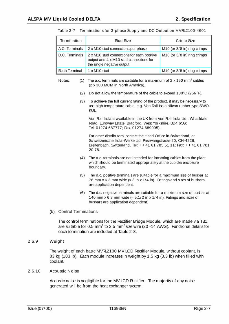
ALSPA MV Liquid Cooled DELTA 2. Specification
Issue (07/00) T1693EN Page 2-7
Table 2-7 Terminations for 3-phase Supply and DC Output on MVRL2100-4601
Termination Stud Size Crimp Size
A.C. Terminals 2 x M10 stud connections per phase M10 (or 3/8 in) ring crimps
D.C. Terminals 2 x M10 stud connections for each positiveoutput and 4 x M10 stud connections forthe single negative output
M10 (or 3/8 in) ring crimps
Earth Terminal 1 x M10 stud M10 (or 3/8 in) ring crimps
Notes: (1) The a.c. terminals are suitable for a maximum of 2 x 150 mm2 cables(2 x 300 MCM in North America).
(2) Do not allow the temperature of the cable to exceed 130oC (266 oF).
(3) To achieve the full current rating of the product, it may be necessary touse high temperature cable, e.g. Von Roll Isola silicon rubber type SIWO-KUL.
Von Roll Isola is available in the UK from Von Roll Isola Ltd., WharfdaleRoad, Euroway Estate, Bradford, West Yorkshire, BD4 6SG;Tel. 01274 687777; Fax. 01274 689095).
For other distributors, contact the Head Office in Switzerland, atSchweizerische Isola-Werke Ltd, Passwangstrasse 20, CH-4226,Breitenbach, Switzerland, Tel: ++41 61 785 51 11; Fax: ++41 61 78120 78.
(4) The a.c. terminals are not intended for incoming cables from the plantwhich should be terminated appropriately at the cubicle/enclosureboundary.
(5) The d.c. positive terminals are suitable for a maximum size of busbar at76 mm x 6.3 mm wide (≈ 3 in x 1/4 in). Ratings and sizes of busbarsare application dependent.
(6) The d.c. negative terminals are suitable for a maximum size of busbar at140 mm x 6.3 mm wide (≈ 5.1/2 in x 1/4 in). Ratings and sizes ofbusbars are application dependent.
(b) Control Terminations
The control terminations for the Rectifier Bridge Module, which are made via TB1,are suitable for 0.5 mm2 to 2.5 mm2 size wire (20 -14 AWG). Functional details foreach termination are included at Table 2-8.
2.6.9 Weight
The weight of each basic MVRL2100 MV LCD Rectifier Module, without coolant, is83 kg (183 lb). Each module increases in weight by 1.5 kg (3.3 lb) when filled withcoolant.
2.6.10 Acoustic Noise
Acoustic noise is negligible for the MV LCD Rectifier. The majority of any noisegenerated will be from the heat exchanger system.
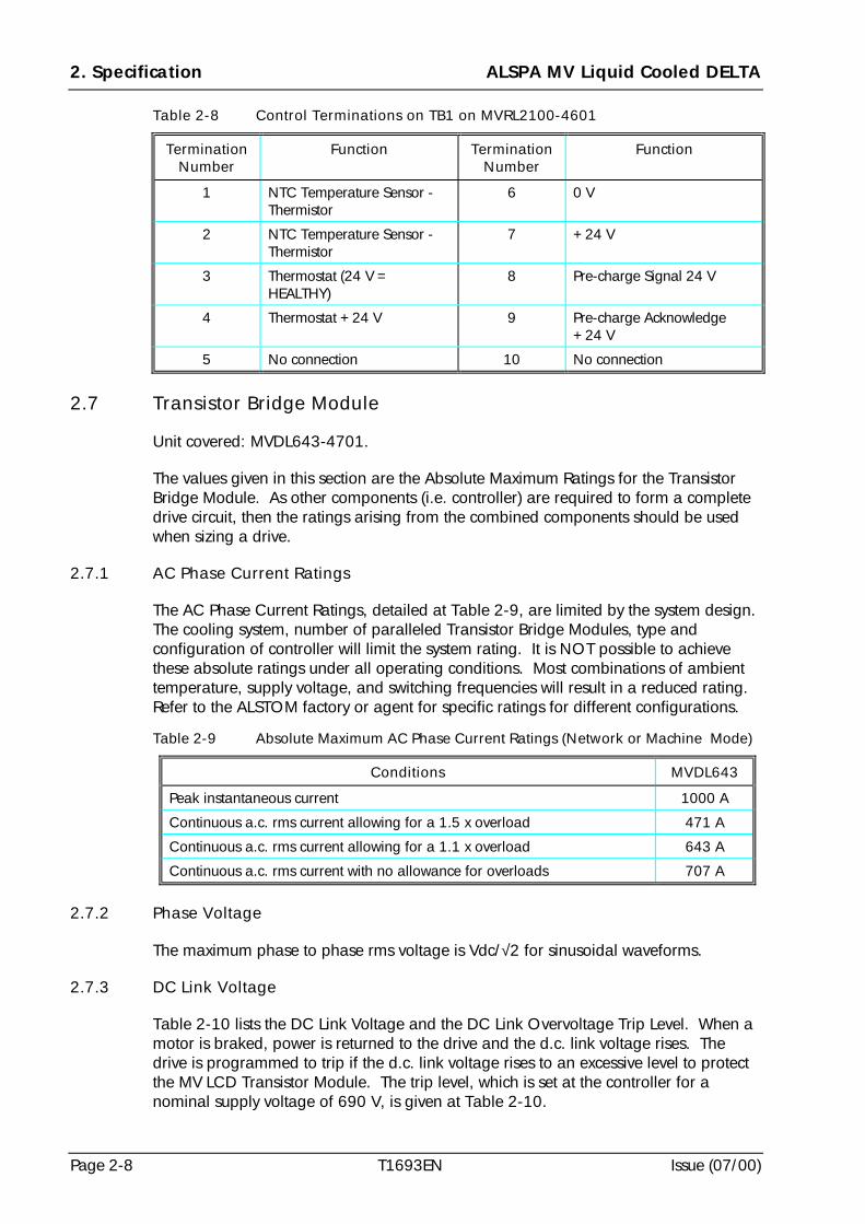
2. Specification ALSPA MV Liquid Cooled DELTA
Page 2-8 T1693EN Issue (07/00)
Table 2-8 Control Terminations on TB1 on MVRL2100-4601
TerminationNumber
Function TerminationNumber
Function
1 NTC Temperature Sensor -Thermistor
6 0 V
2 NTC Temperature Sensor -Thermistor
7 +24 V
3 Thermostat (24 V =HEALTHY)
8 Pre-charge Signal 24 V
4 Thermostat +24 V 9 Pre-charge Acknowledge+24 V
5 No connection 10 No connection
2.7 Transistor Bridge Module
Unit covered: MVDL643-4701.
The values given in this section are the Absolute Maximum Ratings for the TransistorBridge Module. As other components (i.e. controller) are required to form a completedrive circuit, then the ratings arising from the combined components should be usedwhen sizing a drive.
2.7.1 AC Phase Current Ratings
The AC Phase Current Ratings, detailed at Table 2-9, are limited by the system design.The cooling system, number of paralleled Transistor Bridge Modules, type andconfiguration of controller will limit the system rating. It is NOT possible to achievethese absolute ratings under all operating conditions. Most combinations of ambienttemperature, supply voltage, and switching frequencies will result in a reduced rating.Refer to the ALSTOM factory or agent for specific ratings for different configurations.
Table 2-9 Absolute Maximum AC Phase Current Ratings (Network or Machine Mode)
Conditions MVDL643
Peak instantaneous current 1000 A
Continuous a.c. rms current allowing for a 1.5 x overload 471 A
Continuous a.c. rms current allowing for a 1.1 x overload 643 A
Continuous a.c. rms current with no allowance for overloads 707 A
2.7.2 Phase Voltage
The maximum phase to phase rms voltage is Vdc/√2 for sinusoidal waveforms.
2.7.3 DC Link Voltage
Table 2-10 lists the DC Link Voltage and the DC Link Overvoltage Trip Level. When amotor is braked, power is returned to the drive and the d.c. link voltage rises. Thedrive is programmed to trip if the d.c. link voltage rises to an excessive level to protectthe MV LCD Transistor Module. The trip level, which is set at the controller for anominal supply voltage of 690 V, is given at Table 2-10.
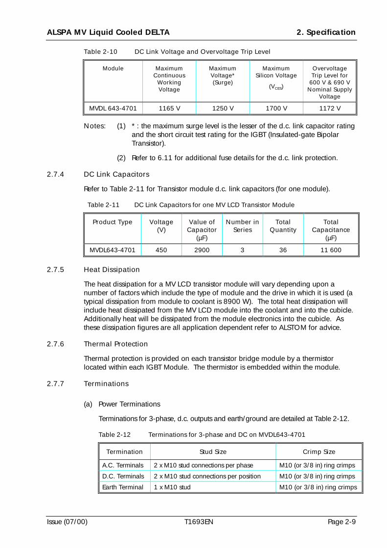
ALSPA MV Liquid Cooled DELTA 2. Specification
Issue (07/00) T1693EN Page 2-9
Table 2-10 DC Link Voltage and Overvoltage Trip Level
Module MaximumContinuous
WorkingVoltage
MaximumVoltage*(Surge)
MaximumSilicon Voltage
(VCES)
OvervoltageTrip Level for
600 V & 690 VNominal Supply
Voltage
MVDL 643-4701 1165 V 1250 V 1700 V 1172 V
Notes: (1) * : the maximum surge level is the lesser of the d.c. link capacitor ratingand the short circuit test rating for the IGBT (Insulated-gate BipolarTransistor).
(2) Refer to 6.11 for additional fuse details for the d.c. link protection.
2.7.4 DC Link Capacitors
Refer to Table 2-11 for Transistor module d.c. link capacitors (for one module).
Table 2-11 DC Link Capacitors for one MV LCD Transistor Module
Product Type Voltage(V)
Value ofCapacitor
(µF)
Number inSeries
TotalQuantity
TotalCapacitance
(µF)
MVDL643-4701 450 2900 3 36 11 600
2.7.5 Heat Dissipation
The heat dissipation for a MV LCD transistor module will vary depending upon anumber of factors which include the type of module and the drive in which it is used (atypical dissipation from module to coolant is 8900 W). The total heat dissipation willinclude heat dissipated from the MV LCD module into the coolant and into the cubicle.Additionally heat will be dissipated from the module electronics into the cubicle. Asthese dissipation figures are all application dependent refer to ALSTOM for advice.
2.7.6 Thermal Protection
Thermal protection is provided on each transistor bridge module by a thermistorlocated within each IGBT Module. The thermistor is embedded within the module.
2.7.7 Terminations
(a) Power Terminations
Terminations for 3-phase, d.c. outputs and earth/ground are detailed at Table 2-12.
Table 2-12 Terminations for 3-phase and DC on MVDL643-4701
Termination Stud Size Crimp Size
A.C. Terminals 2 x M10 stud connections per phase M10 (or 3/8 in) ring crimps
D.C. Terminals 2 x M10 stud connections per position M10 (or 3/8 in) ring crimps
Earth Terminal 1 x M10 stud M10 (or 3/8 in) ring crimps
2. Specification ALSPA MV Liquid Cooled DELTA
Page 2-10 T1693EN Issue (07/00)
Notes: (1) The a.c. terminals are suitable for a maximum of 2 x 120 mm2 cables(250 MCM in North America).
(2) Do not allow the temperature of the cable to exceed 130 oC (266 oF).
(3) To achieve the full current rating of the product, it may be necessary touse high temperature cable, e.g. Von Roll Isola silicon rubber typeSIWO-KUL.
Von Roll Isola is available in the UK from Von Roll Isola Ltd., WharfdaleRoad, Euroway Estate, Bradford, West Yorkshire, BD4 6SG;Tel. 01274 687777; Fax. 01274 689095).
For other distributors, contact the Head Office in Switzerland, atSchweizerische Isola-Werke Ltd, Passwangstrasse 20, CH-4226,Breitenbach, Switzerland, Tel: ++41 61 785 51 11; Fax: ++41 61781 20 78.
(4) The a.c. terminals are not intended for incoming cables from the plantwhich should be terminated appropriately at the cubicle/enclosureboundary.
(5) The d.c. terminals are suitable for a maximum size of busbar at 6.3 mmx 70 mm wide (≈ 1/4 in x 2. 3/4 in). Ratings and sizes of busbars areapplication dependent.
(b) Control Terminations
The control terminations for the Transistor Bridge Module are detailed at Table 2-13. The connectors are supplied with the product.
Table 2-13 Terminations for Control Circuits on Transistor BridgeModule MVDL643-4701 (excluding ribbon cables)
Termination Connector Type
DC Feedback/ SMPS supply AMP Mate-n-Lok (2way)
Control signals 1 x 40 way ribbon connector
2.7.8 Weight
The weight of the MVDL643 Transistor Module, without coolant, is 95 kg (210 lb). Themodule increases in weight by 1.5 kg (3.3 lb) when filled with coolant.
2.7.9 Acoustic Noise
Acoustic noise is negligible for the MV LCD Transistor Bridge Module. There will be asmall amount of noise from the fan assembly which houses the cooling fans for the d.c.link capacitors and this will be 52 dB(A). However, the majority of any noise generatedwill be from the heat exchanger system and this will be specific to each application.
2.8 Switched Mode Power Supplies (SMPS) for MV LCD Systems
One MV SMPS unit, detailed at Table 2-14, must be fitted to each Transistor BridgeModule.
ALSPA MV Liquid Cooled DELTA 2. Specification
Issue (07/00) T1693EN Page 2-11
Table 2-14 MV SMPS Power Supply Specification
Order Number MVC3003-4003
Nominal Drive Supply Voltage (Va.c.) 575 - 690 V (600 V nominal)
SMPS Supply Fed from d.c. link of MV LCD TransistorModule
Start Up Voltage (Vd.c.) 550
Overvoltage Trip (V) 1172
Undervoltage Trip (V) 560
Output Power (W) 110
Maximum Ambient (°C) 50
Weight in kg (lb) 1.5 kg (3.3 lb)
2.9 Three-phase Sharing Reactors
2.9.1 Network Bridge
For MV3000 applications, network bridge sharing reactors have been implementedwithin the network line reactor (see Table 2-15) as necessary. The network line reactoris suitable for use with a maximum of two parallel DELTA transistor modules.
Table 2-15 Sinusoidal Network/Sharing Reactor
Drive NominalSupplyVoltage
(V)
ReactorCurrent
Rating Ia.c.
(A) (rms)
PhaseInductance
(mH)
Rreactor
(mΩ)
Weight
(kg)
Order No.
MVDL643-4701 690 986 0.385 0.85 1050 50Z0081/01
2.9.2 Machine Bridge
To ensure current sharing between multiple transistor bridges it is recommended thatthe cabling to the machine is star connected at the motor terminals. A minimum cablelength of 20 metres must be maintained to achieve sufficient inductance for the sharingfunction.
2.10 Interbridge Transformer
2.10.1 Weight and Resistance
These naturally ventilated transformers are used with 12 pulse input rectifier systems -see Table 2-16.
Table 2-16 Interbridge Transformer - Weight and Resistance
Reactor OrderNumber
Nominal SupplyVoltage (V)
Approx. Weight(kg) (lb)
Rreactor
(mΩΩΩΩ))))
50Z0119/02 690 160 352 0.27
2. Specification ALSPA MV Liquid Cooled DELTA
Page 2-12 T1693EN Issue (07/00)
2.10.2 Terminations
Customer connections at A1, A2 and A3 on the Interbridge Transformer 50Z0119/02should be with M12 bolts (or 1/2 in) with cable ring crimps.
2.10.3 Losses
Power loss = Idc2 x Rreactor x 0.325 Watts
where Rreactor is in ohms and Idc is in Amperes
2.11 MV LCD Module Cooling System
The cooling system for the MV LCD rectifier and transistor modules uses an ethyleneglycol type of liquid coolant (full specification is at Section 3). There are particularrequirements for specification of the:
(a) cooling system - including all the requirements external to the liquid cooledmodules;
(b) control, protection and instrumentation for the cooling system;
(c) compatibility rules for liquids and materials which may come into contact with thecoolant or the cooling system.
Because these are all important aspects of the specification, which involve the user inthe design of a cooling system, all the specification requirements are included atSection 3 - COOLING SYSTEM DESIGN. However, those details which relatespecifically to the Liquid Cooled modules, are specified in this Section 2.
2.11.1 Type and Concentration of Coolant
The recommended coolant type is an ethylene glycol water mixture with a minimumconcentration of 33% for the ethylene glycol. Refer to 3.7.2 and 3.7.3 for additionaldetails.
2.11.2 Volume and Weight of Coolant in each MV LCD Module
The volume of coolant in each MV LCD module, Rectifier and Transistor, is 1.75 litres(≈ 0.38 UK gallon or ≈ 0.46 US gallon); weight of coolant is 1.75 kg (4 lb).
2.11.3 Coolant Flow Rate
The recommended flow rate, per module, for the coolant is 25 litres/minute (5.5 UKgallons/minute or 6.6 US gallons/minute).
2.11.4 Pressure Drop across a MV LCD Module
The pressure drop measured across a single MV LCD module, including the couplings,is typically 0.3 bar (30 kPa) at a flow rate of 25 litres/minute (5.5 UK gallons/minute or6.6 US gallons/minute); variation of glycol concentration does not affect this pressuredrop.
ALSPA MV Liquid Cooled DELTA 2. Specification
Issue (07/00) T1693EN Page 2-13
2.11.5 Cooling System Working Pressure
The maximum working pressure for the cooling system is 3 bar (0.3 MPa). Themaximum pressure for testing purposes only is 6 bar (0.6 MPa) for short durations.
2.11.6 Coolant Inlet Temperature
The maximum coolant inlet temperature is 60 oC (140 oF) - measured at the inlet to thecooling duct.
2.11.7 Material Compatibility in Cooling Path
It is important that all materials in the cooling path are compatible with each other andwith the type of ethylene glycol coolant in use (see 3.7.2). Because the external coolingpath is specified by a system integrator and the equipment is not normally suppliedwith the MV LCD module it is important that material compatibility is maintained. Thematerials which are used in the MV LCD Cooling Path, and those which are acceptablefor the external cooling path, are listed in this specification at Tables 2-17 and 2-18respectively. Table 2-19 lists materials which are known to be incompatible with othermaterials in the MV LCD cooling path. This list is not fully inclusive and thereforesystem integrators must check intercompatibility.
Table 2-17 Materials Used in the MV LCD Cooling Path
COMPONENT MATERIAL AND SPECIFICATION
Staubli Quick Release HoseCouplings
RMI16 N007 117 96 - SKT and
RMI16 N007 153 98 - PLG
Main Parts in brass CuZn40Pb3 - Nickel platedRelease Sleeve in Stainless Steel Z30 CF13
Plug Body in hardened Chromium Steel Z30 CF13
Locking Balls in Stainless Steel Z2 CN18.09
Seals in EPDM Ethylene Propylene
Springs in Stainless Steel Z10 CN18.09
Drain Plug - ALSTOM
Part No. 51Y0653/01
Main Body - Stainless Steel Grade 316
Washer - Stainless Steel Grade 316
‘O’ ring for washer - EPDM Ethylene Propylene
Bleed Plug Assembly - ALSTOM
Bleed Plug Part No. 51Y0651/01
Bleed Screw Part No. 51Y0652/01
Bleed Plug Main Body - Stainless Steel Grade 316
Washer - Stainless Steel Grade 316
‘O’ ring for washer - EPDM Ethylene Propylene
Bleed Screw - Brass (grade unspecified)
Coolant Duct Aluminium LM25 to BS 1490
Heatplate Aluminium LM25 to BS 1490
Heatplate ‘O’ ring Nitrile Rubber NI 70 (008-N70)
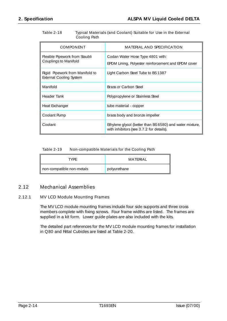
2. Specification ALSPA MV Liquid Cooled DELTA
Page 2-14 T1693EN Issue (07/00)
Table 2-18 Typical Materials (and Coolant) Suitable for Use in the ExternalCooling Path
COMPONENT MATERIAL AND SPECIFICATION
Flexible Pipework from StaubliCouplings to Manifold
Codan Water Hose Type 4801 with:
EPDM Lining, Polyester reinforcement and EPDM cover
Rigid Pipework from Manifold toExternal Cooling System
Light Carbon Steel Tube to BS 1387
Manifold Brass or Carbon Steel
Header Tank Polypropylene or Stainless Steel
Heat Exchanger tube material - copper
Coolant Pump brass body and bronze impeller
Coolant Ethylene glycol (better than BS 6580) and water mixture,with inhibitors (see 3.7.2 for details).
Table 2-19 Non-compatible Materials for the Cooling Path
TYPE MATERIAL
non-compatible non-metals polyurethane
2.12 Mechanical Assemblies
2.12.1 MV LCD Module Mounting Frames
The MV LCD module mounting frames include four side supports and three crossmembers complete with fixing screws. Four frame widths are listed. The frames aresupplied in a kit form. Lower guide plates are also included with the kits.
The detailed part references for the MV LCD module mounting frames for installationin Q80 and Rittal Cubicles are listed at Table 2-20.
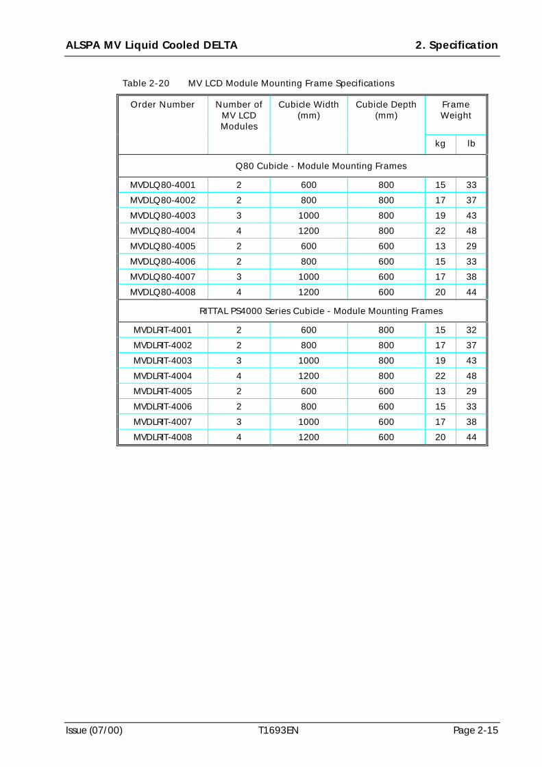
ALSPA MV Liquid Cooled DELTA 2. Specification
Issue (07/00) T1693EN Page 2-15
Table 2-20 MV LCD Module Mounting Frame Specifications
FrameWeight
Order Number Number ofMV LCDModules
Cubicle Width(mm)
Cubicle Depth(mm)
kg lb
Q80 Cubicle - Module Mounting Frames
MVDLQ80-4001 2 600 800 15 33
MVDLQ80-4002 2 800 800 17 37
MVDLQ80-4003 3 1000 800 19 43
MVDLQ80-4004 4 1200 800 22 48
MVDLQ80-4005 2 600 600 13 29
MVDLQ80-4006 2 800 600 15 33
MVDLQ80-4007 3 1000 600 17 38
MVDLQ80-4008 4 1200 600 20 44
RITTAL PS4000 Series Cubicle - Module Mounting Frames
MVDLRIT-4001 2 600 800 15 32
MVDLRIT-4002 2 800 800 17 37
MVDLRIT-4003 3 1000 800 19 43
MVDLRIT-4004 4 1200 800 22 48
MVDLRIT-4005 2 600 600 13 29
MVDLRIT-4006 2 800 600 15 33
MVDLRIT-4007 3 1000 600 17 38
MVDLRIT-4008 4 1200 600 20 44
2. Specification ALSPA MV Liquid Cooled DELTA
Page 2-16 T1693EN Issue (07/00)
(This page intentionally left blank)
ALSPA MV Liquid Cooled DELTA 3. Cooling System Design
Issue (07/00) T1693EN Page 3-1
3. Cooling System Design
3.1 Introduction
The MV Liquid Cooled DELTA (MV LCD) module liquid cooling system depends uponspecific requirements for each particular application and therefore requires separateconsideration of its design at the system integration stage. This section, which includesdetails relating specifically to the Cooling System Design, should also be read inconjunction with Section 2 - SPECIFICATION which includes all the specifications forthe MV LCD modules. The details included in this Section 3, for Cooling SystemDesign, include integration of the cooling system control, protection andinstrumentation features within the drive system and outline specifications for thehardware and coolant required for a complete cooling system. Outline specificationsare included for the heat exchanger, the coolant pump, the header tanks andassociated fittings and all piping and couplings. A detailed specification is included forthe coolant and guidance is given about safe use, handling and disposal of therecommended coolants. A typical cooling system is shown at Figure 3-1.
Throughout this section of the manual reference to a MV LCD Module should be readas applying to either a Rectifier Module or a Transistor Module unless a type of moduleis specifically stated.
3.2 Cooling System Integration Requirements
Requirements for integration of the control, protection and instrumentation features ofthe cooling system with the drive controller depend upon each particular application.Some of these features are included as standard on a MV LCD module, e.g.measurement of heatsink temperature by thermistor, and inputs for the related controland protection circuits are already available within the MV3000 controller. However,other features which are not included as standard on the module, may also beconsidered at the system integration stage. Both standard and non-standard featuresfor control, protection and instrumentation are now listed. The lists are not fullyinclusive and special application conditions may include more extensive requirements.
3.2.1 Control
Control, and interlocking with system design, may be required for the following:
(a) co-ordination of coolant pump and heat exchanger operation;
(b) coolant pump ‘switch off’ when coolant temperature is low;
(c) economic use of the heat exchanger fan by controlled intermittent operation;
(d) drive start not permitted because the coolant temperature is too low.
WARNINGHealth Hazards of Liquid CoolantsThe coolant used in this equipment may be hazardous to health if not stored,handled and disposed of in accordance with the manufacturer’s instructions.
3. Cooling System Design ALSPA MV Liquid Cooled DELTA
Page 3-2 T1693EN Issue (07/00)
3.2.2 Protection
Protection for the following conditions may be required:
(a) pump not running;
(b) coolant not flowing;
(c) coolant level too low;
(d) low pressure in cooling system
(e) coolant temperature too low for drive to start;
(f) coolant temperature too high for safe operation;
(g) module overtemperature;
(h) heat exchanger in thermal overload;
(i) heat exchanger fan not running therefore coolant temperature too high.
3.2.3 Instrumentation
Instrumentation for measuring or indicating the following coolant conditions may be required:
(a) inlet temperature;
(b) outlet temperature;
(c) pressure;
(d) level;
(e) flow rate;
(f) pump not running.
3.3 Heat Exchanger - Requirement Specification
The heat exchanger, which is not included with the MV LCD module, should bespecified by the system integrator. To assist with that specification Table 3-1 lists thosefeatures which should be considered and specified at the system integration stage for aliquid-to-air heat exchanger; liquid-to-liquid types may also be used. The exact detailswill depend upon each particular application, including, for example, the number ofMV LCD modules which have to be cooled.
When designing the heat exchanger please refer to Section 2 - SPECIFICATION, in thismanual, which includes details of typical heat dissipation from the MV LCD modulesand their associated electronics. These heat dissipation figures should provide a basisfor calculations of the heat exchanger size for each particular application. Thespecification for material compatibility in the cooling system is also included at Section2 and this should be implemented.
Detailed consideration should be given to the operating altitude whereby de-ratingmay be required for the heat exchanger.
Protection of the heat exchanger for thermal overload conditions may also be requiredand this should also be specified during system design.
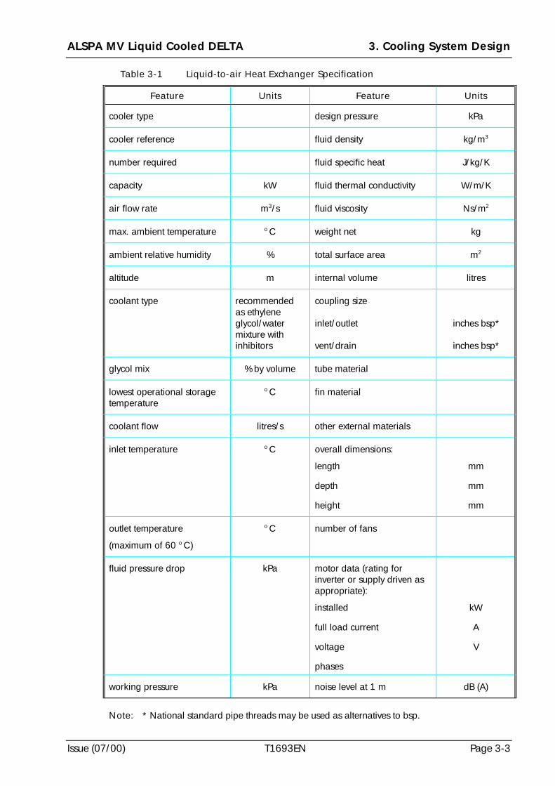
ALSPA MV Liquid Cooled DELTA 3. Cooling System Design
Issue (07/00) T1693EN Page 3-3
Table 3-1 Liquid-to-air Heat Exchanger Specification
Feature Units Feature Units
cooler type design pressure kPa
cooler reference fluid density kg/m3
number required fluid specific heat J/kg/K
capacity kW fluid thermal conductivity W/m/K
air flow rate m3/s fluid viscosity Ns/m2
max. ambient temperature o C weight net kg
ambient relative humidity % total surface area m2
altitude m internal volume litres
coolant type recommendedas ethyleneglycol/watermixture withinhibitors
coupling size
inlet/outlet
vent/drain
inches bsp*
inches bsp*
glycol mix % by volume tube material
lowest operational storagetemperature
o C fin material
coolant flow litres/s other external materials
inlet temperature o C overall dimensions:
length
depth
height
mm
mm
mm
outlet temperature
(maximum of 60 o C)
o C number of fans
fluid pressure drop kPa motor data (rating forinverter or supply driven asappropriate):
installed
full load current
voltage
phases
kW
A
V
working pressure kPa noise level at 1 m dB (A)
Note: * National standard pipe threads may be used as alternatives to bsp.
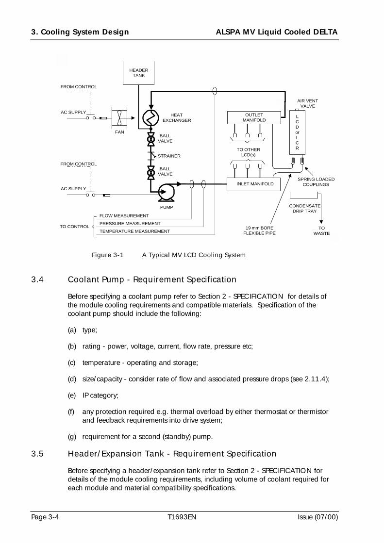
3. Cooling System Design ALSPA MV Liquid Cooled DELTA
Page 3-4 T1693EN Issue (07/00)
3.4 Coolant Pump - Requirement Specification
Before specifying a coolant pump refer to Section 2 - SPECIFICATION for details ofthe module cooling requirements and compatible materials. Specification of thecoolant pump should include the following:
(a) type;
(b) rating - power, voltage, current, flow rate, pressure etc;
(c) temperature - operating and storage;
(d) size/capacity - consider rate of flow and associated pressure drops (see 2.11.4);
(e) IP category;
(f) any protection required e.g. thermal overload by either thermostat or thermistorand feedback requirements into drive system;
(g) requirement for a second (standby) pump.
3.5 Header/Expansion Tank - Requirement Specification
Before specifying a header/expansion tank refer to Section 2 - SPECIFICATION fordetails of the module cooling requirements, including volume of coolant required foreach module and material compatibility specifications.
AC SUPPLY
HEATEXCHANGER
PUMP
STRAINER
FROM CONTROL
TO CONTROL
FLOW MEASUREMENT
PRESSURE MEASUREMENT
TEMPERATURE MEASUREMENT
CONDENSATEDRIP TRAY
19 mm BOREFLEXIBLE PIPE
SPRING LOADEDCOUPLINGS
TO OTHERLCD(s)
AIR VENTVALVE
INLET MANIFOLD
AC SUPPLY
FROM CONTROL
BALLVALVE
BALLVALVE
TOWASTE
LCDorLCR
OUTLETMANIFOLD
FAN
HEADERTANK
Figure 3-1 A Typical MV LCD Cooling System
ALSPA MV Liquid Cooled DELTA 3. Cooling System Design
Issue (07/00) T1693EN Page 3-5
Specification of the tank should include consideration of the following:
(a) whether a fully sealed system is required;
(b) type of header tank;
(c) size of tank - when determining the size allow for the volume of coolant in allmodules, all pipework, pumps, manifolds and header tank;
(d) material for tank should be compatible with the module material specification (seeSection 2);
(e) position of tank in relation to cubicle housing the modules.
3.6 Piping, Couplings and Fittings - Requirement Specification
There are several important factors to consider when specifying the piping, couplingsand fittings for the MV LCD Cooling System. These factors relate to the number ofmodules, the materials used in the cooling system, their temperature andenvironmental specifications. Refer to Section 2 - SPECIFICATION for details of thoserequirements. All materials for piping and couplings should be compatible with themodule material specification at Section 2. Specification of the piping, couplings andfittings for a multiple arrangement of modules (i.e. more than one) should include thefollowing:
(a) possible use of a cooling system design that includes a by-pass around the heatexchanger to minimise the possibility of condensation occurring on those parts ofthe cooling system enclosed in the cubicle;
(b) the flow and return pipes should be positioned to ensure equalisation of coolantflow when piping to multiple modules e.g. the first connection from the inletmanifold connects to the FLOW coupling of the first liquid cooled product. TheRETURN coupling from this module would connect to the last (end) connection ofthe outlet manifold - see Figure 3-1;
(c) each liquid cooled module is fitted with two ‘spring loaded’, ‘auto shut-off’couplings - one for FLOW and one for RETURN. Two mating parts, StaubliUnimation Part RMI 16 type N00711796 socket hose couplings, are suppliedloose with each module. These hose couplings are suitable for 19 mm (3/4 in)internal bore hose;
(d) pipes (flexible) - specification of flexible pipes from the MV LCD module to thecubicle manifold are included at Table 3-2 where typical, flexible high qualityrubber pipes, manufactured, for example, by Codan Gummi A/S of Denmark aredetailed – adequate fixings should also be specified to ensure that the pipes arefully located onto the coupling and firmly held in place by a clamp;
Note: Suitable clamps are Oetiker 2-Ear-Clamps available in the U.K. fromOetiker U.K. Ltd – Tel. +44(0) 1403 26 04 78 and also availableinternationally from the same company.
(e) pipes (rigid) - specification of rigid pipes recommended for couplings from thecubicle manifold to heat exchanger/pump are detailed at Table 3-3, based onBS 21;
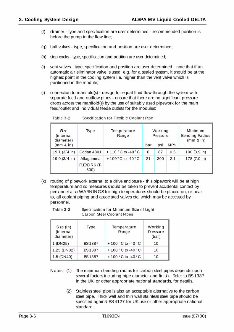
3. Cooling System Design ALSPA MV Liquid Cooled DELTA
Page 3-6 T1693EN Issue (07/00)
(f) strainer - type and specification are user determined - recommended position isbefore the pump in the flow line;
(g) ball valves - type, specification and position are user determined;
(h) stop cocks - type, specification and position are user determined;
(i) vent valves - type, specification and position are user determined - note that if anautomatic air eliminator valve is used, e.g. for a sealed system, it should be at thehighest point in the cooling system i.e. higher than the vent valve which ispositioned in the module;
(j) connection to manifold(s) - design for equal fluid flow through the system withseparate feed and outflow pipes - ensure that there are no significant pressuredrops across the manifold(s) by the use of suitably sized pipework for the mainfeed/outlet and individual feeds/outlets for the modules;
Table 3-2 Specification for Flexible Coolant Pipe
Size(internaldiameter)(mm & in)
Type TemperatureRange
WorkingPressure
bar psi MPa
MinimumBending Radius
(mm & in)
19.1 (3/4 in) Codan 4801 +110 o C to -40 o C 6 87 0.6 100 (3.9 in)
19.0 (3/4 in) Alfagomma
FLEXOR 6 (T-800)
+100 o C to -40 o C 21 300 2.1 178 (7.0 in)
(k) routing of pipework external to a drive enclosure - this pipework will be at hightemperature and so measures should be taken to prevent accidental contact bypersonnel also WARNINGS for high temperatures should be placed on, or nearto, all coolant piping and associated valves etc. which may be accessed bypersonnel.
Table 3-3 Specification for Minimum Size of LightCarbon Steel Coolant Pipes
Size (in)(internaldiameter)
Type TemperatureRange
WorkingPressure
(bar)
1 (DN25) BS 1387 +100 o C to -40 o C 10
1.25 (DN32) BS 1387 +100 o C to -40 o C 10
1.5 (DN40) BS 1387 +100 o C to -40 o C 10
Notes: (1) The minimum bending radius for carbon steel pipes depends uponseveral factors including pipe diameter and finish. Refer to BS 1387in the UK, or other appropriate national standards, for details.
(2) Stainless steel pipe is also an acceptable alternative to the carbonsteel pipe. Thick wall and thin wall stainless steel pipe should bespecified against BS 4127 for UK use or other appropriate nationalstandard.
ALSPA MV Liquid Cooled DELTA 3. Cooling System Design
Issue (07/00) T1693EN Page 3-7
3.7 Coolant
WARNINGS!!!! Type of Liquid Coolant
Only use a recommended coolant with corrosion inhibitors.
!!!! Mixing Liquid CoolantsDo not mix coolants of different types or from different manufacturers.
!!!! Water without Corrosion InhibitorsDo not use water as the only coolant. Mix water with corrosion inhibitor orethylene glycol containing corrosion inhibitor.
3.7.1 Coolant Inlet Temperature at the Module Cooling Duct
The maximum cooling system inlet temperature, measured at the entry point of thecoolant into the module cooling duct on the module, is 60oC.
The ambient temperature of the coolant is application dependent and should includeconsideration of heat from all the pumps, heat exchangers and pipework etc.
The inlet temperature should always be qualified as either that for the coolant duct orthat for the total cooling system. The latter will be feeding several modules and possiblyother equipment as determined by the application and the temperature will thereforediffer from that measured at the entry point to a single module.
3.7.2 Coolant Type
The coolant mixture recommended for use with the MV LCD modules is an EthyleneGlycol and Water mixture.
The coolant should meet the performance specification of BS 6580 or the equivalentnational standard. It must provide:
(a) corrosion protection;
(b) frost protection;
(c) scale inhibitors (against hard water);
(d) all year usage.
Two types of recommended coolant are detailed below. A local supplier of coolant(antifreeze) can be used providing that it complies with the requirements in (a) to (d)and is compatible with the materials specified at Table 2-17 and Table 2-18. However, it is important that these coolants, or any others from differentmanufacturers, are NOT MIXED in the cooling system.
Note: Ethylene Glycol based coolants are NOT normally compatible withpolyurethane which should therefore not be included in the cooling system.
3. Cooling System Design ALSPA MV Liquid Cooled DELTA
Page 3-8 T1693EN Issue (07/00)
Recommended U.K. based coolant suppliers are:
(1) ESKIMO UNIVERSAL ANTIFREEZE from:FUCHS LUBRICANTS (UK) PLC
SILKOLENE OIL REFINERY
BELPER
DERBYSHIRE
DE56 1WF
U.K.
Tel. +44(0)1773 824151 Fax. +44(0)1773 823659
(2) COMMA SUPERCOLDMASTER ANTIFREEZE from:COMMA OIL & CHEMICALS LIMITED
LOWER GRANGE ROAD
GRAVESEND
KENT
DA12 2QX
U.K.
Tel. +44(0)1474 564311 Fax. +44(0)1474 333000
3.7.3 Coolant Mixture and Concentration
Coolant and pure or de-mineralised water should be used to prepare the coolantmixture.
The coolant mixture concentration depends upon the minimum external ambienttemperature to avoid the possibility of freezing - refer to the manufacturer’srecommendations for a coolant concentration to meet your requirements. There arefour particular conditions which must be noted when determining the concentration ofcoolant viz:
(a) as the percentage of ethylene glycol within a coolant mixture increases, theefficiency of the coolant to remove heat from a module reduces slightly;
(b) concentrations of ethylene glycol above approximately 50% offer no furtherprotection against low temperatures.
(c) concentrations of ethylene glycol above approximately 75% provide less lowtemperature protection.
(d) a minimum concentration of 33% Ethylene Glycol must be included with thecooling system to ensure adequate corrosion protection.
3.7.4 Volume of Coolant in a System
The volume of coolant required for a cooling system depends upon the particularapplication and should consider the volumes of coolant required for:
ALSPA MV Liquid Cooled DELTA 3. Cooling System Design
Issue (07/00) T1693EN Page 3-9
(a) all the modules;
(b) all the cooling pipes;
(c) header/expansion tank;
(d) manifold(s);
(e) evaporation loss between planned maintenance.
Refer to Section 2 - SPECIFICATION for the capacity of coolant in each module.
3.7.5 Separation of Different Coolant Types
It is recommended that the coolant used for MV LCD modules be kept separate fromany other coolants used at the same location. It is also important that differentmanufacturer’s types of coolant are not mixed in the same MV LCD cooling system.
3.7.6 Rate of Flow and Cooling Rate
Before specifying the rate of flow for cooling requirements refer to Section 2 -SPECIFICATION for the cooling rates and heat dissipation figures for each module.Because cooling rates are affected by heat dissipation, ambient temperatures, coolantvolumes etc. calculations for the required cooling rate and flow rate will depend uponeach particular application.
The rate of flow, which is application dependent, should typically be 25 litres/minute.
3.7.7 Renewal of Coolant
Renewal of coolant is described at Section 8 - MAINTENANCE.
3.7.8 Handling, Storage and Disposal of Coolant
The coolant is subject to particular conditions during handling, storage and disposal.Refer to the manufacturer’s instructions for the particular coolant in use. It isrecommended that the instructions be retained with this manual.
Detailed advice for safe handling, storage and disposal is included at Section 8 -MAINTENANCE. Disposal of the coolant and/or its container should be done inaccordance with the manufacturer’s instructions to ensure compliance with local andnational Health, Safety and Environmental legislation.
3. Cooling System Design ALSPA MV Liquid Cooled DELTA
Page 3-10 T1693EN Issue (07/00)
(This page is intentionally left blank)
ALSPA MV Liquid Cooled DELTA 4. Cubicle Planning
Issue (07/00) T1693EN Page 4-1
4. Cubicle Planning
4.1 Introduction
This section gives guidance for the selection, planning and installation of MV LiquidCooled DELTA (MV LCD) Drive Systems. As each application has differentrequirements, this section only gives general rules and information. Requirements forElectromagnetic Compatibility are included at 4.4 and these should be implementedduring the Cubicle Planning stage.
4.2 Guidance for the Selection of MV LCD Products
If the drive is non-standard the following selection procedure is included for guidancewhen confirming that the products ordered for a particular application are suitable:
1. Calculate the application current rating based on a 1.1 times (variable torque)overload for 60 seconds, 6 times per hour.
2. Select the appropriate MV LCD configuration. The standard supply voltage rangeis 575 - 690 V. Apply de-rating factors (ambient temperature and altitude etc.). Select the appropriate number of MVDL643-4701s to achieve the current ratingfor the application.
3. Select one ALSPA MV3000 DELTA Controller.
4. One MV DELTA User I/O Termination Panel is required.
5. Choose a quantity of Switch Mode Power Supplies (SMPS(s)) - one per MV LCDInverter Module.
6. Corresponding to the required DELTA rating select the appropriate MVRL rectifiermodule.
The rectifier designation is in d.c. current in Amps, i.e.
MVRL2100 = 2100 A d.c..
To relate rectifier rating to inverter module rating the conversion factor is:
a.c. current = 0.85 x d.c. current
Note: It is important to note that when two MV LCD rectifier modules areparalleled a 10% derate should be applied for load sharing reasons.
As with MV LCD inverter modules, extra care should be taken with calculationswhen required current ratings are very close to (i.e. just under) the module rating.
WARNINGLocal Safety Regulations
Follow all local safety regulations for electrical equipment when planningand installing Liquid Cooled DELTA based systems.
4. Cubicle Planning ALSPA MV Liquid Cooled DELTA
Page 4-2 T1693EN Issue (07/00)
7. Rectifier module MVRL2100 is designed for cable connection.
8. For multiple MV LCD Inverter Modules output sharing is achieved by independentcabling from the inverter to a star point at the motor.
9. Choose the appropriate interbridge reactor for 12-pulse rectifier configurations.
10. Choose the appropriate Cable Assembly Kit.
11. Choose the size and quantity of MV LCD module mounting frames to cover thenumber of modules i.e. rectifiers and inverters, and also to suit the desired cubiclewidth(s) and depth(s).
12. Select Technical Manuals.
13. End of selection procedure.
4.3 General Considerations for the Enclosure of MV LCD Drives
When planning for the installation of MV LCD components into a cubicle there aresome general design considerations which have an effect on the overall performanceof the drive system and also affect its compliance with various standards andapprovals.
4.3.1 Enclosure Type
Essential requirements for the enclosure are that:
(a) The MV LCD modules must be enclosed in a steel (conductive) enclosure for:
- electrical safety - all doors must be closed and all unnecessary aperturesavoided;
- reduction of radiated emissions from the drive and protection of the drive fromradiating sources.
(b) The enclosure must provide a Pollution Degree 2 Environment, in accordance withIEC 60664-1, UL 840 and CSA 22.2 No. 0.2, for the MV LCD systemcomponents.
Note: Refer to Section 2 for the specification of an enclosure to meet aPollution Degree 2 Environment.
(c) The assembly and connection of all parts should be done using the torque settingsat Appendix B.
4.3.2 Enclosure Sizes
4.3.2.1 600 mm (23.6 in) Deep Enclosure
The MV LCD modules and components may be mounted in a range of different sizedenclosures - see Table 2-19 for cubicle/enclosure widths and depths. However, whena 600 mm (23.6 in) deep enclosure is used, careful planning is required because somecomponents use the full enclosure depth.
Also on 600 mm wide enclosures the horizontal mounting position of a module isoffset 20 mm further to the left on the 600 mm cross rails than on all other versions.
ALSPA MV Liquid Cooled DELTA 4. Cubicle Planning
Issue (07/00) T1693EN Page 4-3
4.3.2.2 800 mm (31.5 in) Deep Enclosure
The side supports for the 800 mm deep cubicles allow for two variations in the fitting ofthe MV LCD modules viz:
(a) modules mounted at the back of the cubicle - pipework and manifolds must thenbe fitted either above and below the cross members or located outside the cubicle.
(b) modules mounted forward of the rear face of the cubicle - this will allow forpipework and manifolds to be mounted on the rear wall of the cubicle behind themodules.
Note: To implement variation (b) the user must purchase an additional lower frontcross member which fixes onto the side supports. The reference dependsupon the cubicle type, quantity of modules and cubicle width; these arelisted at Table 4-1.
Table 4-1 Details of Additional Lower Front Cross Member
Cubicle Width(mm)
Cubicle Manufacturer and Type
ALSTOM Q80 RITTAL PS4000
600 50Y7585/01 50Y9724/01
800 50Y7589/01 50Y9720/01
1000 50Y7593/01 50Y9728/01
1200 50Y6945/01 50Y9732/01
4.3.3 Position of Rectifier Bridge Module
It is recommended that the Rectifier Bridge Module be mounted on the right hand sideof a cubicle (front view), with space to the right of the module, for the followingreasons:
(a) access to d.c. positive and negative cable connections on the right hand side ofthe module;
(b) access to the d.c. link pre-charge fuses which are located on the printed circuitboard at the rear of the module;
(c) access for tidy routing of cables from the d.c. connections;
(d) most cubicle doors are hinged on the left, so door interlocked isolators aremounted on the right of the cubicle.
4.3.4 Position of MV3000 Controller
The MV3000 controller is designed for mounting on the left or right hand side sheets ofa cubicle housing MV LCD modules. There are certain constraints which apply to theposition of the controller, and its associated modules, and User I/O Termination Paneland these are:
4. Cubicle Planning ALSPA MV Liquid Cooled DELTA
Page 4-4 T1693EN Issue (07/00)
(a) wherever the controller is mounted allow a 50 mm (2 in) ventilation space aboveand below the controller;
(b) arrange for the controller to be mounted with front access for the LED(s) andsufficient space for access to all the connecting plugs, sockets and terminations;
(c) allow sufficient space around the controller for the routing and retention of allassociated cables;
(d) arrange for User I/O Termination Panel to be mounted on the same side of thecubicle as the controller to minimise any EMC problems (refer to 6.8 for details) -ensure that the cable routing distance for the 50 way ribbon cable from PL20, atthe controller, to the User I/O Termination Panel does not exceed 2 m (6.5 ft);
(e) ensure that the cable routing distance for each of the six 40 way ribbon cablesfrom the controller to each module does not exceed the lengths supplied - refer to6.3.1 for details of cable lengths;
(f) ensure that the cable routing distance for the cable from PL12 to a Network Bridge Rectifier does not exceed 25 m (82 ft);
(g) ensure that the optional Drive Data Manager (Keypad), when used, is mountedin a position which is within the 3 m (9.8 ft) cable length for connection to thecontroller at SK5 - this dimension will influence controller position;
(h) ensure that the cable routing distance for the 50 way ribbon cable from PL20, atthe controller, to the User I/O Termination Panel does not exceed 2 m (6.5 ft).
4.3.5 Position of MV Switched Mode Power Supply (SMPS)
There is one SMPS for each MV LCD Transistor Bridge Module. It is mounted on theupper front face of the module from which it derives a d.c. power supply.
4.4 Electromagnetic Compatibility (EMC) Requirements
There are particular requirements for Electromagnetic Compatibility (EMC) compliance. These requirements are determined, to some extent, by the application for which theMV LCD system is being used. However, there are some general guidelines which canbe used to ensure that the equipment is EMC compliant. These guidelines are listed at4.4.1 to 4.4.5.
4.4.1 General Application Guidance
There is some general application guidance for the MV LCD equipment as follows:
(a) When the equipment is being used in a ‘second environment’ (industrialenvironment) in accordance with IEC 61800-3 then EMC filters are not normallyrequired.
(b) If the equipment is installed on a public low voltage supply which also suppliesdomestic premises (‘first environment’ according to IEC 61800-3) then EMCfiltering will be required.
(c) Filtering will also be required if other items connected to the same supply aresensitive to radio frequency interference or would normally be used in domesticenvironments.
ALSPA MV Liquid Cooled DELTA 4. Cubicle Planning
Issue (07/00) T1693EN Page 4-5
(d) EMC filters may only be used if the supply neutral is connected to earth/ground atthe source of the supply (also known as TN or TT network).
(e) If EMC filters are to be used and there are also thyristor converters (e.g. d.c.drives) on the same supply, any commutation notches from these converters mustnot exceed 40%,
(f) If an EMC filter is fitted, it must be mounted on to a metal panel which is directlybolted to the metal framework of the cubicle.
4.4.2 EMC Requirements for The Enclosure
There are particular EMC requirements that apply to an enclosure housing MV LCDequipment as follows:
(a) Clean air cooling apertures in the enclosure should be fitted with EMC screenfilters.
(b) The gland plate for input/output cables must be bolted directly to the enclosurewalls, or to metal framework to which the outer walls are electrically bonded. Gland plates should not to be spaced off, even on metal pillars or bars and directmetal-to-metal contact must be achieved for earth continuity and low electricalnoise purposes.
(c) Module mounting rails must be secured to the metal frame of the enclosure, toachieve high mechanical strength and good earth bonding for electrical safetyand EMC.
(d) If more than one enclosure is used for the MV LCD module system, bond thesesecurely together making a ‘continuous enclosure’. This bonding should be bydirect metal-to-metal contact, not by braids or cables. If it is not practical to havethese enclosures adjacent, use armoured cable or conduit, glanded to eachenclosure.
4.4.3 Reactors and other Iron-cored Components
Wound components (e.g. reactors, transformers, interbridge transformers etc.) emitmagnetic fields and protection is required. The following guidance is given for suchmagnetic components in the MV LCD equipment:
(a) wound components must be installed in a steel enclosure to prevent emission ofradiation - for electrical safety, all terminals should be shrouded to preventaccidental contact.
Note: These components will usually be mounted on the floor of theenclosure as they are large and heavy.
(b) Additionally air-cored reactors must have a minimum segregation of 300 mm(12 in).
4.4.4 Routing and Segregation of Cables
The routing and segregation of cables, including separation distances and directions ofcable routing, can all contribute to the performance of the equipment. The followingguidance is given for cables in the MV LCD equipment:
4. Cubicle Planning ALSPA MV Liquid Cooled DELTA
Page 4-6 T1693EN Issue (07/00)
(a) Wiring between the mains input and an RFI (Radio Frequency Interference) filtermust be segregated by a minimum of 300 mm (12 in) from all other drive anddrive output components, i.e. modules, inductors and motor cable.
(b) Control and power wiring must cross at 90° and be separated by a minimum of300 mm (12 in).
(c) Ribbon cables supplied with MV LCD kits should be run along earthed metal andnot through mid-air. Use the ribbons supplied, do not extend these ribbons. If theribbons are too long, fold the excess length backward and forward (do not roll) tomake a low-inductance bundle (see Table 6-1 and Figure 6-5).
(d) The MV3000 controller should be mounted in the same enclosure, or suite ofenclosures as the MV LCD modules.If the controller is fitted to a hinged gate, this should be mounted directly to themetal frame of the enclosure. There are length restrictions from the controller to thefurthest module, due to the ribbon cable lengths as detailed in Section 6 -ELECTRICAL INSTALLATION.
(e) The User I/O Termination Panel should be mounted in the same enclosure as thecontroller and with a ‘metal-to-metal’ contact with the enclosure frame.
The Ribbon Cable from the User I/O Termination Panel to the controller should berun along earthed metal and not through mid-air. Again, there are distancerestrictions, check that the ribbon cables will reach - cable length is 2 m (6.5 ft).These ribbons should be segregated by approximately 300 mm (12 in) from powercables and from external plant wiring.
4.4.5 Protection of Cables Routed Outside the Enclosure
All cables which are routed outside the MV LCD enclosure - e.g. plant wiring wherethere is a requirement for screening, segregation, terminations etc. - require protectionwhich would normally be determined by the application but generally follow the rulesalready described in this section.
4.5 Cubicle Planning
4.5.1 General Guidance
The Cubicle Planning details are intended for users who have been supplied with a kitof MV LCD components for which an enclosure has to be provided. Guidance is givenfor planning of that enclosure for assembly of the components.
(a) List the items to be installed - a typical component list is included, as an example,at Table 4-2.
(b) Assess the approximate size and weight of the individual items.
(c) Understand how the items are supported and mechanically interact - refer to theappropriate assembly details at Section 5 - MECHANICAL INSTALLATION.
Note: The horizontal mounting position of the modules is offset 20 mmfurther to the left on the 600 mm wide cross rails than on all otherversions for Q80 and Rittal PS4000 Series Cubicles.
ALSPA MV Liquid Cooled DELTA 4. Cubicle Planning
Issue (07/00) T1693EN Page 4-7
(d) If the equipment is to be mounted in an 800 mm deep enclosure, with spaceallowed at the back of the modules for coolant manifolds and/or pipework, thenensure that the upper and the lower front cross members are positionedappropriately. Note that an additional front cross member is required in the rearlocation.
(e) Decide on the positions of the network and machine bridge modules as follows:
- refer to guidance at 4.3.3 for the rectifier module position;
- allow a 50 mm (2 in) ventilation space above the upper cross member;
(f) Ensure that the cooling requirements are adequate, in particular, that:
- a clean air supply is available for the electronics;
- minimum clearances are complied with for ventilation above and below thecontroller - see 5.10 and Figure 5-11.
- the external cooling system has been designed in accordance with theguidance at Section 3 - COOLING SYSTEM DESIGN;
- all the piping and connectors for each MV Liquid Cooled module are installedin the cubicle in accordance with the recommendations at Section 5 -MECHANICAL INSTALLATION;
(g) Cabling - consider:
- cable sizes and routing - ensure that the modules can be cabled together;
- access to main and control connections of the modules;
(h) Detail the mechanical interfaces required for installation of the drive - these shouldinclude:
- any additional brackets required to locate the module mounting frame withinthe cubicle;
- air inlet on cubicle door;
- mounting of the controller;
- the main cabling glanding/ terminals in/out of the cubicle.
(i) Ensure that any additional contract dependent components have been includede.g. fuses, isolator, circuit breakers.
(j) Ensure that all components are assembled in the sequence given at 4.6 and that:
- sufficient clearance is allowed to fit those components;
- additional components are fitted in positions that do not obstruct the removaland replacement of any modules.
4. Cubicle Planning ALSPA MV Liquid Cooled DELTA
Page 4-8 T1693EN Issue (07/00)
4.5.2 Example of a MV31929 12 Pulse Input Drive
4.5.2.1 Component List
The list of components required for the drive should be discussed with ALSTOM at thetime of ordering. Table 4-2 lists typical components that are required for a MV LCDdrive. Mounting details for the components are included at Section 5 - MECHANICALINSTALLATION.
Figure 4-1 shows a typical cubicle layout for the components included in this example.
4.5.2.2 MV31929 Cubicle Layout
The drive components listed at Table 4-1 may be mounted in an ALSTOM Q80Cubicle, a Rittal PS4000 Series cubicle or another equivalent cubicle for which themounting frames are described at Section 5 - MECHANICAL INSTALLATION.
The lower guide plates, cross members and side supports are all attached together andso form a sub-assembly (the dimensions of these are shown at Figure 5-1). The MVLCD modules slide into this sub-assembly.
The horizontal position of the modules within the cubicle is set by their position on thelower cross members. This spacing is defined by the pitch required between themodules. The front to back location of the cross members, and hence the modules, isset by the side supports. The default location is with the module at the back of thecubicle. For the 800 mm deep cubicle, however, the module can be moved forward toallow for pipework and coolant manifolds to be located behind the module - refer to4.3.2.2 and Table 4-1 for details.
The vertical position is determined by the cubicle planner and is dependent on anycomponents that are to be fitted, either underneath or above the modules, and also theposition of manifolds.
The enclosure shown at Figure 4-1 represents a MV31929 drive installed in a2200 mm high, 1200 mm wide, 800 mm deep cubicle. The components shown arethose that are mandatory for this size of drive.
In addition to the mandatory components (see Table 4-2) other optional and usersupplied components, as listed at the table, may also be specified by the user.
The interbridge transformer should be mounted on the cubicle floor as it is large andheavy.
The controller should be attached to a side panel and positioned towards the front ofthe cubicle; refer to 4.3.4 for general information about positioning the controller.
Cooling requirements should be considered. Fans for cubicle ventilation, and theirposition, should also be specified by the user.
4.5.3 Cubicle Access
If cubicle access is required, either at rear or side, for auxiliary components then themodules must be fully enclosed to prevent accidental contact with potentially livevoltages.
ALSPA MV Liquid Cooled DELTA 4. Cubicle Planning
Issue (07/00) T1693EN Page 4-9
4.6 Installation Sequence
Guidance is given for a recommended sequence of installing the MV LCD components. Some pre-assembly checks are also included to minimise any delays during assembly.
4.6.1 Checks prior to Assembly
The following checks should be made before starting the assembly of any MV LCDcomponents:
(a) all required items are available - check against a list of parts for the drive system;
(b) module mounting frames - note particularly the details as follows:
- width of frames to be assembled (2, 3 or 4 module);
- module types to be fitted in each frame and their positions;
- positions and types of reactor required;
- cooling requirements & equipment;
(c) cubicle layout includes sufficient clearance to fit each component and, to latergain access if required for servicing.
4.6.2 Sequence of Assembly
The MV LCD components and cooling system pipework should be assembled in thefollowing sequence:
- module mounting frames - assemble into the selected cubicle;
- lower guide plates;
- cooling system pipework;
- drip tray;
- modules;
- Switched Mode Power Supply to the Transistor Bridge Module;
- d.c. link fuses, when required;
- a.c. input fuses and isolators;
- User I/O Termination Panel;
- MV3000 Controller;
- Drive Data ManagerTM ;
- cubicle ventilation fans;
- other ancillary components.
4.7 Module Mounting Frame Sizes
Sizes of the module mounting frames for a range of cubicle sizes are included atSection 2 - SPECIFICATION.
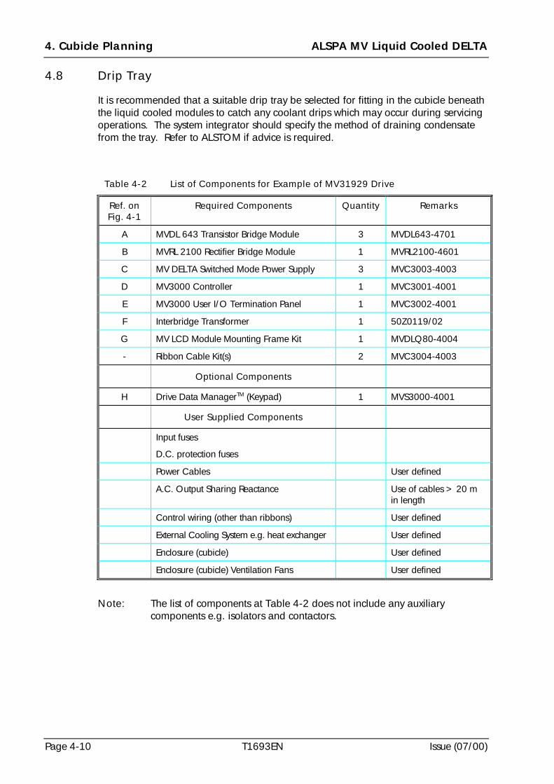
4. Cubicle Planning ALSPA MV Liquid Cooled DELTA
Page 4-10 T1693EN Issue (07/00)
4.8 Drip Tray
It is recommended that a suitable drip tray be selected for fitting in the cubicle beneaththe liquid cooled modules to catch any coolant drips which may occur during servicingoperations. The system integrator should specify the method of draining condensatefrom the tray. Refer to ALSTOM if advice is required.
Table 4-2 List of Components for Example of MV31929 Drive
Ref. onFig. 4-1
Required Components Quantity Remarks
A MVDL 643 Transistor Bridge Module 3 MVDL643-4701
B MVRL 2100 Rectifier Bridge Module 1 MVRL2100-4601
C MV DELTA Switched Mode Power Supply 3 MVC3003-4003
D MV3000 Controller 1 MVC3001-4001
E MV3000 User I/O Termination Panel 1 MVC3002-4001
F Interbridge Transformer 1 50Z0119/02
G MV LCD Module Mounting Frame Kit 1 MVDLQ80-4004
- Ribbon Cable Kit(s) 2 MVC3004-4003
Optional Components
H Drive Data ManagerTM (Keypad) 1 MVS3000-4001
User Supplied Components
Input fuses
D.C. protection fuses
Power Cables User defined
A.C. Output Sharing Reactance Use of cables > 20 min length
Control wiring (other than ribbons) User defined
External Cooling System e.g. heat exchanger User defined
Enclosure (cubicle) User defined
Enclosure (cubicle) Ventilation Fans User defined
Note: The list of components at Table 4-2 does not include any auxiliarycomponents e.g. isolators and contactors.
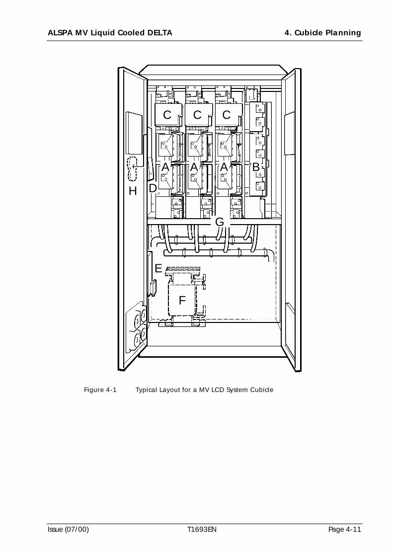
ALSPA MV Liquid Cooled DELTA 4. Cubicle Planning
Issue (07/00) T1693EN Page 4-11
CCC
E
F
D
B
H
G
AAA
Figure 4-1 Typical Layout for a MV LCD System Cubicle
4. Cubicle Planning ALSPA MV Liquid Cooled DELTA
Page 4-12 T1693EN Issue (07/00)
(This page intentionally left blank)
ALSPA MV Liquid Cooled DELTA 5. Mechanical Installation
Issue (07/00) T1693EN Page 5-1
5. Mechanical Installation
5.1 Introduction
This section of the manual describes the mechanical installation of the items which arespecific to an ALSPA MV Liquid Cooled DELTA (MV LCD) system.
Before starting any installation work reference should be made to Sections 4 and 6 ofthis manual. Section 4 - CUBICLE PLANNING includes details about preparation andplanning for installation and Section 6 - ELECTRICAL INSTALLATION includesguidance for the electrical installation of components.
Note: References in this section to 'left' and 'right' should be taken to mean theviewer's left and right when facing the front of a module.
5.2 Receipt and Storage of Equipment
Before starting work the contents of the kit supplied should be carefully unpacked andinspected. Check the complete assignment against the delivery note for any shortagesor loss in transit.
Damaged or missing parts must be reported immediately to the supplier and thefollowing details quoted:
(a) list of damaged or missing items with names and part numbers;
(b) description of damage;
(c) delivery/advice note numbers and dates, and order and item numbers.
If the equipment delivered to site is not to be installed immediately:
(1) re-pack it in its original packaging material - if this is not possible it should beenclosed in polythene sheet to protect it from the ingress of dust;
(2) store it in a clean dry atmosphere, preferably at room temperature - DO NOTEXCEED the storage temperature limits referred to in 2.2;
(3) ensure that, if the equipment is stored for a long period of time, usually greaterthan two years, the equipment supplier is contacted for advice about reforming thed.c. link capacitors before the equipment is put into service;
WARNINGS! Heavy Weights
Items marked with weights greater than 20 kg should only be movedwith lifting apparatus.
! Exposed High Voltages
Enclose all items exposing high voltage before the equipment isenergised.
5. Mechanical Installation ALSPA MV Liquid Cooled DELTA
Page 5-2 T1693EN Issue (07/00)
(4) if the equipment is unpacked in a warm environment condensation may occur - ifcondensation is seen do not use the equipment until its temperature has stabilisedto that of the working environment;
(5) ensure that a liquid cooled module, i.e. rectifier or inverter, is stored without anycoolant loaded in it.
Note: Whenever possible retain and store the original packing materials for use ifa product has to be returned for repair to an ALSTOM factory or service centre.
5.3 Cooling Requirements
To ensure cooling efficiency for the power devices in the modules it is important thatthe following checks be carried out prior to coolant being loaded into the coolingsystem:
(a) all modules have been assembled in the appropriate module mounting frame;
(b) all couplings for the cooling fluid pipes are correctly made and the externalcooling system has been appropriately designed (see Section 3 - COOLINGSYSTEM DESIGN);
(c) all flexible pipes are securely fastened within the cubicle/enclosure which housesthe modules;
(d) all materials used in the external cooling system are compatible with the materialsin the module cooling path (see Section 2 - SPECIFICATION for details of thecompatible materials);
(e) the cooling system, external to the module(s), has been checked for integrity.
The general cubicle/enclosure environment must dissipate the heat generated by thecontrol equipment and all ancillary devices. The maximum heat dissipation into thegeneral cubicle/enclosure from the MV LCD equipment varies for each application. Themaximum heat dissipation is given in Section 2 - SPECIFICATION. The enclosure internaltemperature must always remain within the equipment operating limits as specified atSection 2. If fans are used to cool the general enclosure environment it may also benecessary for the air inlet to be filtered, depending on the local atmospheric conditions.
5.4 Module Mounting Frame Dimensions
The standard kit of parts includes a mounting frame for installing the equipment intostandard ALSTOM Q80 style cubicles, or Rittal PS4000 series cubicles (see 2.12). Thekit however, does not include the cubicles. If another style of enclosure is to be used itwill be necessary to construct suitable brackets to mimic the Q80 mounting points tosupport the MV LCD frame inside the selected cubicle. Advice should be obtainedfrom ALSTOM prior to designing any mounting steelwork.
Figure 5-1 shows the relative positions of the upper and lower cross members and fourside supports (and fixing hole centres) of the frame which must be interfaced with anenclosure (e.g. Q80 type). The mountings of the lower side supports and rear crossmember must be strong enough to support the total weight of the MV LCD moduleswith the frame and cabling/busbars. The weights of the modules and these componentsare listed at Section 2 - SPECIFICATION.
ALSPA MV Liquid Cooled DELTA 5. Mechanical Installation
Issue (07/00) T1693EN Page 5-3
There is an option to mount the modules in one of two positions of depth in an800 mm deep cubicle - see 5.5.2 and 5.6.2.
5.5 Assembling Module Mounting Frames for Q80 Cubicles
5.5.1 General
The frames are available in two cubicle depths and four cubicle widths for mounting upto two, three, or four modules side-by-side. The eight frames are all of similarconstruction, with the lengths of the cross members that determine the overall framewidth, and the side supports which determine the cubicle depth varying for eachcubicle size. These instructions may be used for any frame.
Prepare suitable mounting arrangements for the frames as described at 5.4. All fixingholes for mounting the frames should be drilled 7 mm (9/32 in) to clear the M6 Taptitescrews supplied. Taptites are self-tapping and may be driven in by hand using pozi-drive screwdrivers.
5.5.2 Side Supports for 600 or 800 mm (23.6 in or 31.5 in) Deep Cubicles
There are four identical side supports that may be fitted to the left or right sides of thecubicle. The top of each of these supports may be identified by either two holes (in600 mm deep side support) or six holes (in 800 mm deep side support), in the top flange - see Figure 5-2 item 1.
Note: Front to back orientation is not important as all of the fixing holes havebeen mirrored about the centre line.
Each side support has two fixing holes at each end which accept the M6 Taptite screwssupplied in the kit. Use four M6 x 12 mm hexagon head earthed-nib Taptite screws tomount each of the four side supports as shown at Figure 5-2 - item A.
For 800 mm deep cubicles, the module can be mounted either flush against the rear of thecubicle or brought forward by approximately 100 mm (4 in) to allow for pipework to befitted inside the cubicle. Refer to 4.3.2 and 4.5.1 for details.
5.5.3 Cross Members
Refer to Figure 5-2, for details and part item numbers, and install the three crossmembers as follows:
(a) Identify the lower rear cross member - item 2. Use four M6 x 12 mm hexagonhead earthed-nib Taptite screws - item B - to mount it to the cubicle steelwork.
(b) Identify the upper cross member - item 3. Use four M6 x 12 mm hexagon headearthed-nib Taptite screws - item C - to mount it between the two upper side-supports. Check that the end flanges are at the bottom.
(c) Identify the lower front cross member - item 4. Use six M6 x 12 mm hexagonhead earthed-nib Taptite screws - item D - to mount it between the two lower side-supports. The threaded inserts should be in the top and front flanges - item E.
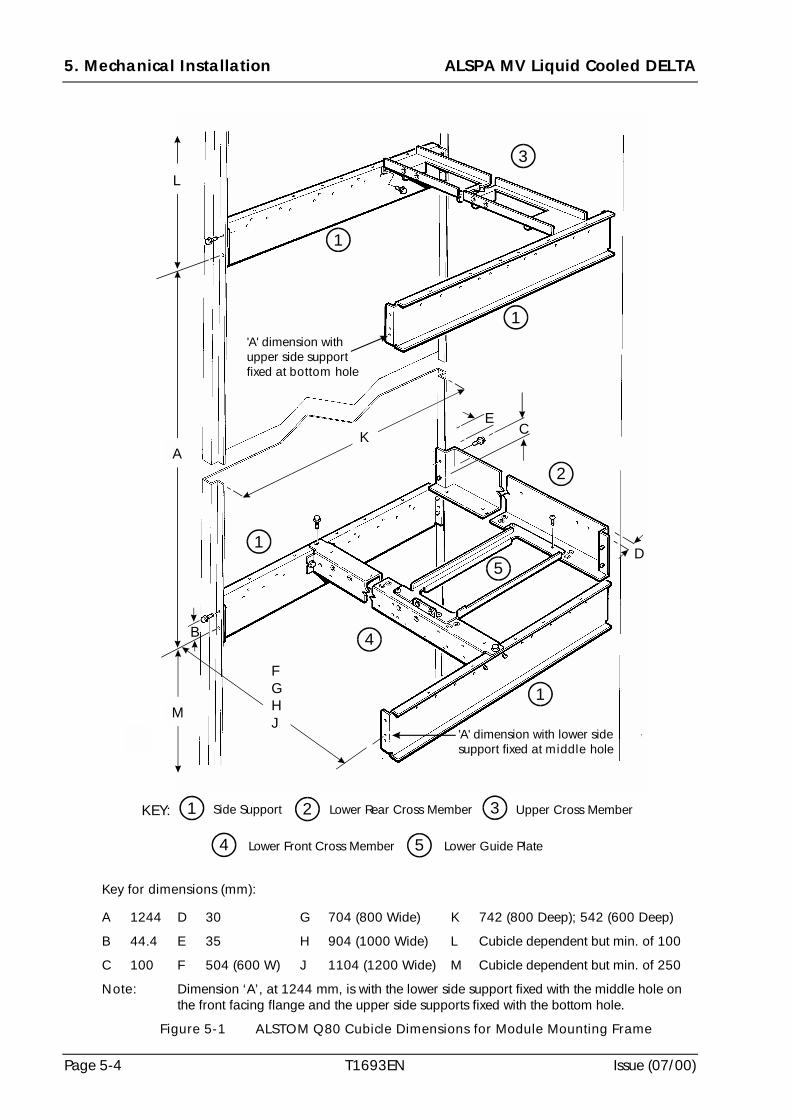
5. Mechanical Installation ALSPA MV Liquid Cooled DELTA
Page 5-4 T1693EN Issue (07/00)
Key for dimensions (mm):
A 1244 D 30 G 704 (800 Wide) K 742 (800 Deep); 542 (600 Deep)
B 44.4 E 35 H 904 (1000 Wide) L Cubicle dependent but min. of 100
C 100 F 504 (600 W) J 1104 (1200 Wide) M Cubicle dependent but min. of 250
Note: Dimension ‘A’, at 1244 mm, is with the lower side support fixed with the middle hole onthe front facing flange and the upper side supports fixed with the bottom hole.
Figure 5-1 ALSTOM Q80 Cubicle Dimensions for Module Mounting Frame
4
1
3
1
1
1
2
5
21KEY: Side Support Lower Rear Cross Member
'A' dimension with lower sidesupport fixed at holemiddle
'A' dimension withupper side supportfixed at holebottom
4 Lower Front Cross Member Lower Guide Plate
3 Upper Cross Member
5
EC
FGHJ
A
D
K
M
L
B
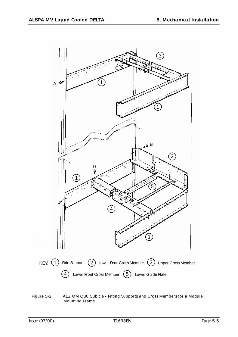
ALSPA MV Liquid Cooled DELTA 5. Mechanical Installation
Issue (07/00) T1693EN Page 5-5
Figure 5-2 ALSTOM Q80 Cubicle - Fitting Supports and Cross Members for a ModuleMounting Frame
4
1
3
1
1
1
2
5
21KEY: Side Support Lower Rear Cross Member
4 Lower Front Cross Member Lower Guide Plate
3 Upper Cross Member
5
A
B
C
D
E
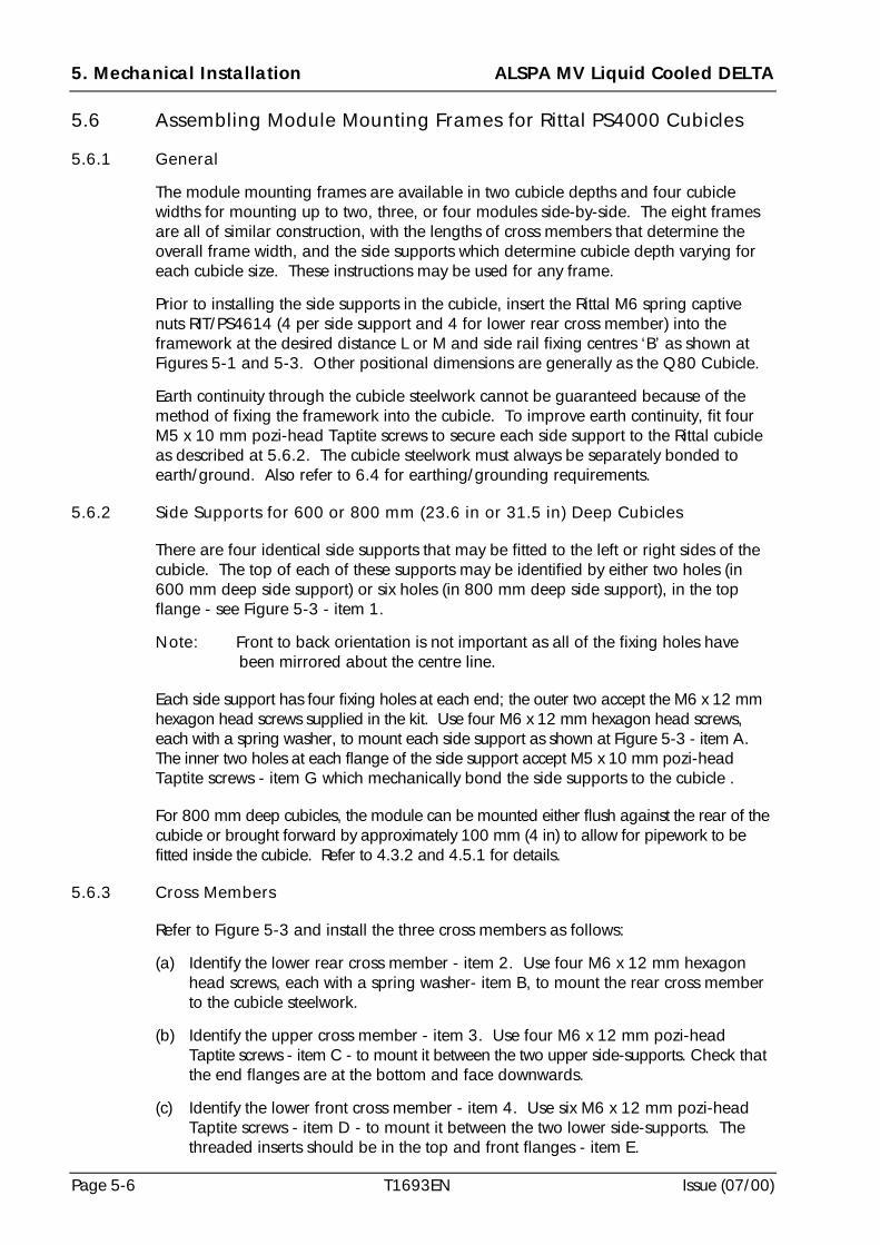
5. Mechanical Installation ALSPA MV Liquid Cooled DELTA
Page 5-6 T1693EN Issue (07/00)
5.6 Assembling Module Mounting Frames for Rittal PS4000 Cubicles
5.6.1 General
The module mounting frames are available in two cubicle depths and four cubiclewidths for mounting up to two, three, or four modules side-by-side. The eight framesare all of similar construction, with the lengths of cross members that determine theoverall frame width, and the side supports which determine cubicle depth varying foreach cubicle size. These instructions may be used for any frame.
Prior to installing the side supports in the cubicle, insert the Rittal M6 spring captivenuts RIT/PS4614 (4 per side support and 4 for lower rear cross member) into theframework at the desired distance L or M and side rail fixing centres ‘B’ as shown atFigures 5-1 and 5-3. Other positional dimensions are generally as the Q80 Cubicle.
Earth continuity through the cubicle steelwork cannot be guaranteed because of themethod of fixing the framework into the cubicle. To improve earth continuity, fit fourM5 x 10 mm pozi-head Taptite screws to secure each side support to the Rittal cubicleas described at 5.6.2. The cubicle steelwork must always be separately bonded toearth/ground. Also refer to 6.4 for earthing/grounding requirements.
5.6.2 Side Supports for 600 or 800 mm (23.6 in or 31.5 in) Deep Cubicles
There are four identical side supports that may be fitted to the left or right sides of thecubicle. The top of each of these supports may be identified by either two holes (in600 mm deep side support) or six holes (in 800 mm deep side support), in the top flange - see Figure 5-3 - item 1.
Note: Front to back orientation is not important as all of the fixing holes havebeen mirrored about the centre line.
Each side support has four fixing holes at each end; the outer two accept the M6 x 12 mmhexagon head screws supplied in the kit. Use four M6 x 12 mm hexagon head screws,each with a spring washer, to mount each side support as shown at Figure 5-3 - item A. The inner two holes at each flange of the side support accept M5 x 10 mm pozi-headTaptite screws - item G which mechanically bond the side supports to the cubicle .
For 800 mm deep cubicles, the module can be mounted either flush against the rear of thecubicle or brought forward by approximately 100 mm (4 in) to allow for pipework to befitted inside the cubicle. Refer to 4.3.2 and 4.5.1 for details.
5.6.3 Cross Members
Refer to Figure 5-3 and install the three cross members as follows:
(a) Identify the lower rear cross member - item 2. Use four M6 x 12 mm hexagonhead screws, each with a spring washer- item B, to mount the rear cross memberto the cubicle steelwork.
(b) Identify the upper cross member - item 3. Use four M6 x 12 mm pozi-headTaptite screws - item C - to mount it between the two upper side-supports. Check thatthe end flanges are at the bottom and face downwards.
(c) Identify the lower front cross member - item 4. Use six M6 x 12 mm pozi-headTaptite screws - item D - to mount it between the two lower side-supports. Thethreaded inserts should be in the top and front flanges - item E.
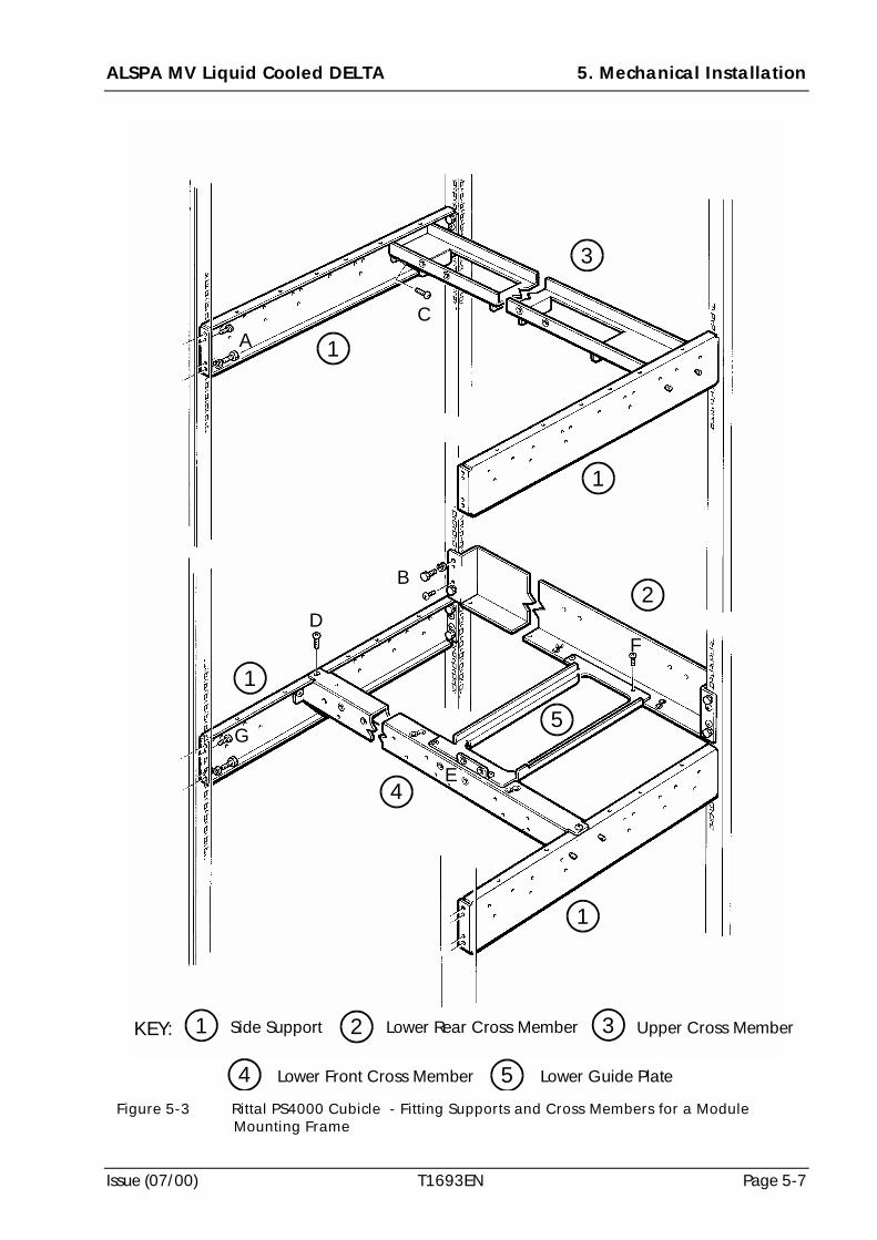
ALSPA MV Liquid Cooled DELTA 5. Mechanical Installation
Issue (07/00) T1693EN Page 5-7
Figure 5-3 Rittal PS4000 Cubicle - Fitting Supports and Cross Members for a ModuleMounting Frame
2
1
1
1
1
4
3
21KEY: Side Support Lower Rear Cross Member
4 Lower Front Cross Member Lower Guide Plate
3 Upper Cross Member
5
5
A
B
C
F
E
D
G
5. Mechanical Installation ALSPA MV Liquid Cooled DELTA
Page 5-8 T1693EN Issue (07/00)
5.7 Lower Guide Plates
Figures 5-1 to 5-3 show a lower guide plate in position in a module mounting frame,for ALSTOM Q80 and Rittal PS4000 Cubicles - item 5. One lower guide plate isrequired for each module mounted in the module frame. It should be installed withfour M5 x 10 mm pozi-head Taptite screws - item F.
5.8 Drip Tray
It is recommended that a drip tray be fitted in the cubicle beneath the liquid cooledmodules to catch any coolant drips which may occur during servicing operations. Themethod of draining condensate from the tray should be specified by the systemintegrator. Refer to ALSTOM if advice is required.
5.9 Modules (Transistor and Rectifier Bridges)
CAUTIONThe modules are delicate and vulnerable to damage - handle carefully.
Only lift or move them by use of the lifting point.
Lay them down on the plain left-hand face when not fitted in a frame.
Do not leave modules unsupported in the upright position.
5.9.1 Guidance for Handling
The MV LCD modules require particular care and attention during handling to ensurethat personnel are not injured or the modules damaged. Figure 5-4 and Figure 5-5show typical Rectifier and Transistor Modules respectively and Figure 5-6 and Figure 5-7 show the outline and fixing dimensions. The lifting arrangement is the same for eachtype of module. They should only be lifted with a crane rated for the module weights,as detailed at Section 2 - SPECIFICATION, and suitable for cubicle access. Themodules should be handled without any pipes attached. All preparatory work shouldbe done in the cubicle/enclosure prior to any module being lifted.
5.9.2 Module Lifting Procedure
(a) Attach the lifting shackle to the module lifting hole, 20 mm (3/4 in) diameter, atthe top of the module - see Figures 5-4 and 5-5.
(b) Lift the module to the appropriate height and move it into position to insert intothe frame - see Figures 5-8 and 5-9.
(c) Tilt the module as it is moved into its slot so that it clears the withdrawal ‘STOPSCREW’ which is built into the bottom right-hand guide - see Figures 5-4, 5-5 & 5-10.
(d) When the rear of the module is located between the guides, lower and push themodule back until it sits on the frame.
(e) Remove the lifting shackle and then push the module firmly into position.
(f) The top and bottom front flanges should now lie against the upper and front lowercross members and the four fixing holes in the flanges should align with the holesin the cross members.
(g) Use four M6 x 12 mm pozi-head screws with plain and spring washers, suppliedwith the mounting frame kits, to secure the module in place - see Figure 5-8.
ALSPA MV Liquid Cooled DELTA 5. Mechanical Installation
Issue (07/00) T1693EN Page 5-9
Figure 5-4 Typical View of a MV LCD Rectifier Bridge Module showing MechanicalDetails
Note : Figure 5-4 does not show details of coolant piping couplings and valveswhich are shown at Figure 5-15. Refer to Figure 6-1 for details of electricalconnections on the module.
Top 2 x M6 clearancefixing holes at 60 mm centres
Bottom 2 x M6clearance fixingholes at 60 mmcentres (behindRemovable Plate)
Lifting hole 20 mm(3/4 in) diameter
Shroud forphase terminals
Shroud for d.c. terminals
Product labelincluding:TypeRatingSerial numberApprovals
Stop Screw(behind insulator)
5. Mechanical Installation ALSPA MV Liquid Cooled DELTA
Page 5-10 T1693EN Issue (07/00)
Note : Figure 5-5 does not show details of coolant piping couplings and valveswhich are shown at Figure 5-15. Refer to Figure 6-4 for details of electricalconnections, and diagnostic LEDs, on the module.
Top 2 x M6 clearancefixing holes
Bottom 2 x M6clearancefixing holes (behindRemovable Plate)
2 x M6 mountingscrews for SMPS
Product label including:TypeRatingSerial numberApprovals
Shroud Stop screw
Lifting hole 20 mm(3/4 in) diameter
Allow aminimum
ventilationspace of
50 mm (2 in)above module
Figure 5-5 Typical View of a MV LCD Transistor Bridge Module showing MechanicalDetails
ALSPA MV Liquid Cooled DELTA 5. Mechanical Installation
Issue (07/00) T1693EN Page 5-11
314 218
Overallheight1263.5
Overall depth 532with shrouds fitted All dimensions in mm
60
60
716
Fixinghole
centres1248.5
246with shrouds fitted
458
Figure 5-6 Outline and Fixing Dimensions for a Rectifier Bridge Module
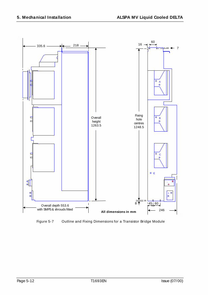
5. Mechanical Installation ALSPA MV Liquid Cooled DELTA
Page 5-12 T1693EN Issue (07/00)
Overall depth 553.6with SMPS & shrouds fitted
E
+
-
C
B
A
60
716
Fixinghole
centres1248.5
60
246
218
Overallheight1263.5
All dimensions in mm
335.6
458
Figure 5-7 Outline and Fixing Dimensions for a Transistor Bridge Module
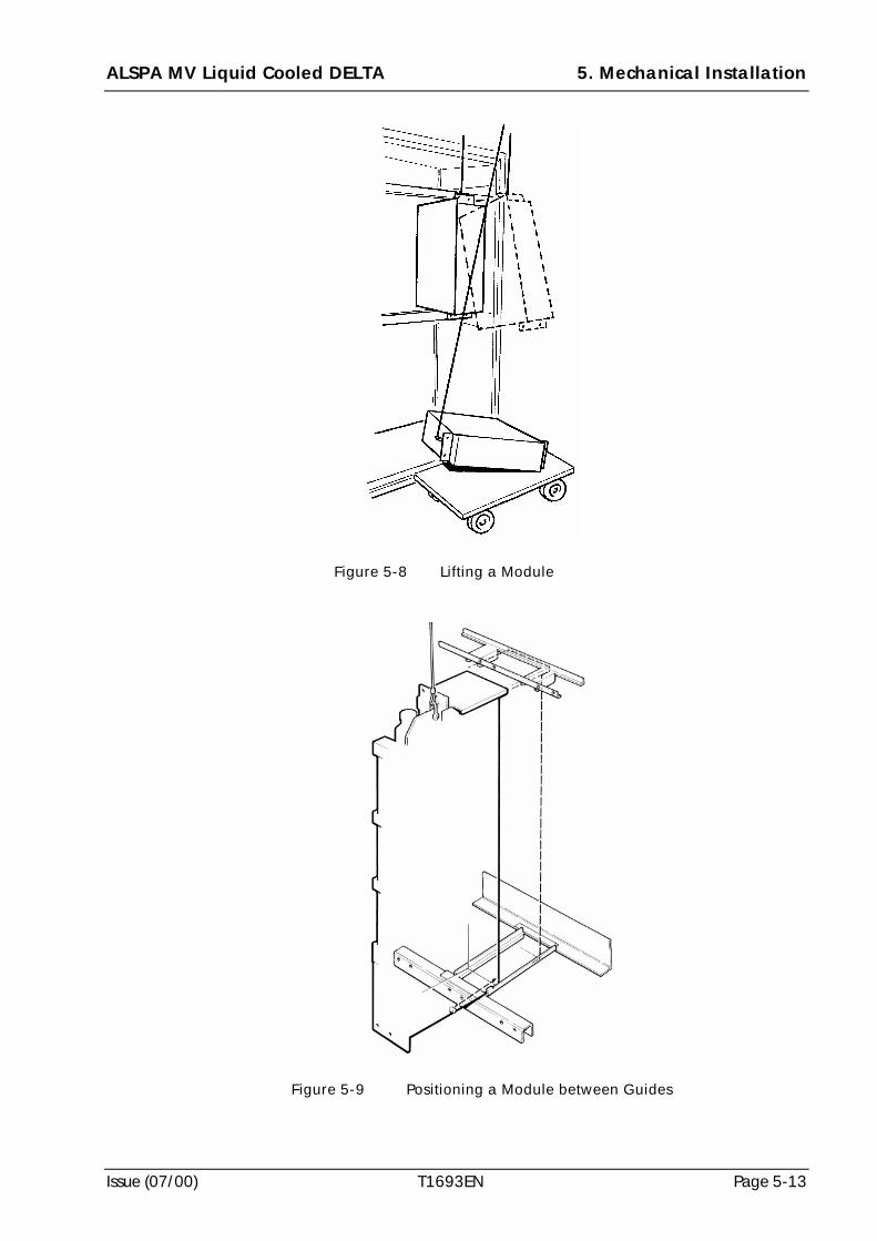
ALSPA MV Liquid Cooled DELTA 5. Mechanical Installation
Issue (07/00) T1693EN Page 5-13
Figure 5-8 Lifting a Module
Figure 5-9 Positioning a Module between Guides
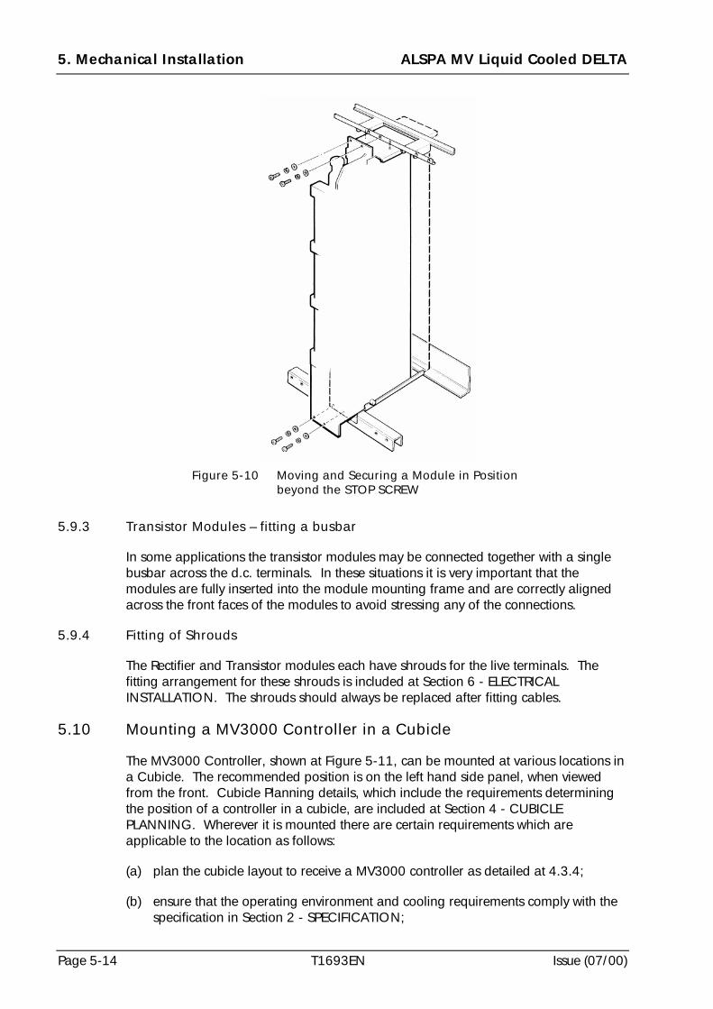
5. Mechanical Installation ALSPA MV Liquid Cooled DELTA
Page 5-14 T1693EN Issue (07/00)
5.9.3 Transistor Modules – fitting a busbar
In some applications the transistor modules may be connected together with a singlebusbar across the d.c. terminals. In these situations it is very important that themodules are fully inserted into the module mounting frame and are correctly alignedacross the front faces of the modules to avoid stressing any of the connections.
5.9.4 Fitting of Shrouds
The Rectifier and Transistor modules each have shrouds for the live terminals. Thefitting arrangement for these shrouds is included at Section 6 - ELECTRICALINSTALLATION. The shrouds should always be replaced after fitting cables.
5.10 Mounting a MV3000 Controller in a Cubicle
The MV3000 Controller, shown at Figure 5-11, can be mounted at various locations ina Cubicle. The recommended position is on the left hand side panel, when viewedfrom the front. Cubicle Planning details, which include the requirements determiningthe position of a controller in a cubicle, are included at Section 4 - CUBICLEPLANNING. Wherever it is mounted there are certain requirements which areapplicable to the location as follows:
(a) plan the cubicle layout to receive a MV3000 controller as detailed at 4.3.4;
(b) ensure that the operating environment and cooling requirements comply with thespecification in Section 2 - SPECIFICATION;
Figure 5-10 Moving and Securing a Module in Positionbeyond the STOP SCREW
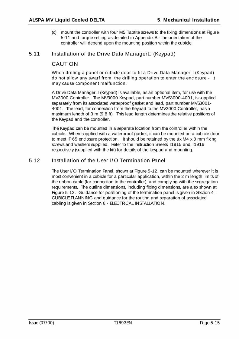
ALSPA MV Liquid Cooled DELTA 5. Mechanical Installation
Issue (07/00) T1693EN Page 5-15
(c) mount the controller with four M5 Taptite screws to the fixing dimensions at Figure5-11 and torque setting as detailed in Appendix B - the orientation of thecontroller will depend upon the mounting position within the cubicle.
5.11 Installation of the Drive Data Manager (Keypad)
CAUTIONWhen drilling a panel or cubicle door to fit a Drive Data Manager (Keypad)do not allow any swarf from the drilling operation to enter the enclosure - itmay cause component malfunction.
A Drive Data Manager (Keypad) is available, as an optional item, for use with theMV3000 Controller. The MV3000 Keypad, part number MVS3000-4001, is suppliedseparately from its associated waterproof gasket and lead, part number MVS3001-4001. The lead, for connection from the Keypad to the MV3000 Controller, has amaximum length of 3 m (9.8 ft). This lead length determines the relative positions ofthe Keypad and the controller.
The Keypad can be mounted in a separate location from the controller within thecubicle. When supplied with a waterproof gasket, it can be mounted on a cubicle doorto meet IP 65 enclosure protection. It should be retained by the six M4 x 8 mm fixingscrews and washers supplied. Refer to the Instruction Sheets T1915 and T1916respectively (supplied with the kit) for details of the keypad and mounting.
5.12 Installation of the User I/O Termination Panel
The User I/O Termination Panel, shown at Figure 5-12, can be mounted wherever it ismost convenient in a cubicle for a particular application, within the 2 m length limits ofthe ribbon cable (for connection to the controller), and complying with the segregationrequirements. The outline dimensions, including fixing dimensions, are also shown atFigure 5-12. Guidance for positioning of the termination panel is given in Section 4 -CUBICLE PLANNING and guidance for the routing and separation of associatedcabling is given in Section 6 - ELECTRICAL INSTALLATION.
5. Mechanical Installation ALSPA MV Liquid Cooled DELTA
Page 5-16 T1693EN Issue (07/00)
Note: Figure 5-11 does not identify electrical connections, or diagnostic LED functions, whichare shown at Figure 6-8.
50 mm (2 in)Fixing Centres
67 mm(2.63 in)
46 mm(1.81 in)
Vertical FixingCentres forholes in tabs is550 mm (21.65 in)
Overallheight is582 mm(22.91 in)
215 mm (8.46 in)
Top 4 x M5 slotted fixingholes - each pair at50 mm (2 in) fixing centres
Allow a minimum ventilationspace of 50 mm (2 in)
above controller
Rating Label
Ventilation Fan
Allow a minimum ventilationspace of 50 mm (2 in)
below controllerBottom 4 x M5slotted fixing holes
Figure 5-11 MV3000 Controller - Mechanical Details
ALSPA MV Liquid Cooled DELTA 5. Mechanical Installation
Issue (07/00) T1693EN Page 5-17
One M5 slottedfixing hole
One M5 slottedfixing hole
One top M4 clearancehole for alternativefixing with DIN Railand metal clip
Three location/retention tabsfor Printed Circuit Boards
One bottom M4clearance hole foralternative fixingwith DIN Railand clip
Terminal Shroud
Five M4 screws to bondcable screens - cablebraid is crimped to M4(No 8 or 3/16 in) ringcrimp
92.5 mm(3.64 in)
310 mm(12.2 in)FixingCentres
325 mm (12.79 in)
Earth stud for use ifadequate bonding/groundingto safety earth/ground notalready achieved
47 mm(1.85 in)
Figure 5-12 User Input/Output Termination Panel - Mechanical Details
5. Mechanical Installation ALSPA MV Liquid Cooled DELTA
Page 5-18 T1693EN Issue (07/00)
5.13 Installation of a MV3000 Switched Mode Power Supply (SMPS)
One MV SMPS fits directly onto the front of each MV LCD Transistor Bridge Module.
Proceed to fit the SMPS, as follows, with reference to Figure 5-13:
(a) Remove the back plate from the module and retain all M6 and M4 fixings;
(b) Fit all the power cabling to the module before fitting the SMPS.
(c) Fix the back plate with the two M6 and two M4 pozi-head fixing screws with plainand spring washers.
(d) Mount the SMPS assembly, using the two locating tabs on the left hand side, andsecure with two M4 Nyloc nuts, supplied, onto the M4 studs.
(e) Remove the blanking plug from TB1 on the Transistor Bridge Module and connectthe DC cable assembly to TB1.
(f) Connect the 40 way ribbon cable from PL3 on the MV DELTA Transistor BridgeModule to PL22 on the SMPS.
TB1Back plate DC cable assembly
Locating tab
SMPS
40 Way ribbon cablefrom PL3 on module
Figure 5-13 Fitting a SMPS to a MV LCD Transistor Bridge Module
ALSPA MV Liquid Cooled DELTA 5. Mechanical Installation
Issue (07/00) T1693EN Page 5-19
5.14 Mounting the Interbridge Transformer (50Z0119/02)
The Interbridge Transformer is a heavy item of equipment and is normally mounted inthe base of a cubicle. Figure 5-14 shows the transformer with its lifting eyes andterminations. Refer to Section 2 - SPECIFICATION for technical details, includingweight, and Appendix A for connection details.
The transformer should be lifted into position, by its M12 lifting eye bolts, with suitablelifting equipment. It should be fixed through the four 13 mm (1/2 in) fixing holes.
Figure 5-14 Interbridge Transformer 50Z0119/02
5.15 Cable Connections between MV LCD Modules and MV3000Controller
Connections between the Rectifier Module and the MV3000 Controller are made bynine individual cables; refer to Figures 6-2 and 6-8.
Connections between the Transistor Module and the MV3000 Controller are made witha 40-way ribbon cable; refer to Figures 6-4 and 6-8. More details for routing of theribbon cables is included at Section 6 - ELECTRICAL INSTALLATION.
Four 13 mm (1/2 in)fixing holes at 280 mm(11.02 in) fixing centresin this direction of view
Fixing holes at180 mm (7.08 in)
fixing centres inthis direction of view
Earth TerminalM12
Two M12 lifting eyebolts
670 mmoverallheightto top ofeyebolts
3 WayTerminal Block
A1 Terminal -13 mm hole
A3 Terminal -13 mm hole
A2 Terminal -14 mm holes
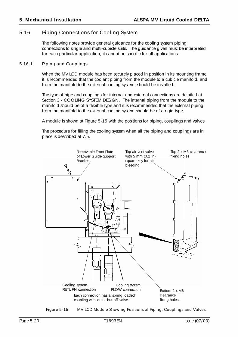
5. Mechanical Installation ALSPA MV Liquid Cooled DELTA
Page 5-20 T1693EN Issue (07/00)
5.16 Piping Connections for Cooling System
The following notes provide general guidance for the cooling system pipingconnections to single and multi-cubicle suits. The guidance given must be interpretedfor each particular application; it cannot be specific for all applications.
5.16.1 Piping and Couplings
When the MV LCD module has been securely placed in position in its mounting frameit is recommended that the coolant piping from the module to a cubicle manifold, andfrom the manifold to the external cooling system, should be installed.
The type of pipe and couplings for internal and external connections are detailed atSection 3 - COOLING SYSTEM DESIGN. The internal piping from the module to themanifold should be of a flexible type and it is recommended that the external pipingfrom the manifold to the external cooling system should be of a rigid type.
A module is shown at Figure 5-15 with the positions for piping, couplings and valves.
The procedure for filling the cooling system when all the piping and couplings are inplace is described at 7.5.
Top air vent valvewith 5 mm (0.2 in)square key for airbleeding
Removable Front Plateof Lower Guide SupportBracket
Top 2 x M6 clearancefixing holes
Bottom 2 x M6clearancefixing holes
Cooling systemconnectionFLOW
Cooling systemconnectionRETURN
Each connection has a 'spring loaded'coupling with 'auto shut-off' valve
Figure 5-15 MV LCD Module Showing Positions of Piping, Couplings and Valves
ALSPA MV Liquid Cooled DELTA 5. Mechanical Installation
Issue (07/00) T1693EN Page 5-21
5.16.2 Recommendations for Routing Pipes into a Cubicle
A typical arrangement of MV LCD modules installed in a cubicle, with all piping andcouplings fitted into position, is shown at Figure 4-1.
Important points to consider when routing and installing the pipes into a cubicle are:
(a) will the external cooling pipes enter the cubicle at top or bottom and have suitablearrangements been made at the cubicle and at the location on site?
(b) particular attention should be given to the position and method of securing themanifolds taking into account the pipe routing which will be dependent uponapplication requirements e.g. from the top or bottom of a cubicle;
(c) ensure equalisation of coolant flows when piping to multiple MV LCD moduleswhich should be arranged on the diagonal principal so that the flow and returnpipes are positioned diagonally opposite across the modules - refer to Figure 3-1.
(d) all flexible piping couplings should have their protective end caps removed priorto the connection being made - the end caps should be stored safely for usewhenever the module is removed or refitted.
5.16.3 Recommendations for Routing Pipes into Multi-cubicle Suites
When routing piping into multi-cubicle suits there are additional recommendationswhich should be observed and these are:
(a) follow the diagonal flow principle for routing pipes to all the cubicles in a suite;
(b) if the diagonal flow principle cannot be used, for any reason, it is important thatother methods of achieving an equalisation of coolant flow through all thecubicles in the suite be considered;
(c) one other method of achieving an equalisation of coolant flow is to use balancingvalves, but when they are used it is important to establish a method of validatingthat equal flow is being achieved in each cubicle in the suite.
5.16.4 Retention and Fitting of Pipe in a Cubicle
Careful consideration should be given to the fitting and retention of all pipes in thecubicle. In particular the following should be considered:
(a) the method of fitting and retaining both flexible and rigid pipes should not restrictaccess to electronic equipment which may have to be removed;
(b) the minimum bending radii of all pipes should not exceed the specificationincluded at Section 3 - COOLING SYSTEM DESIGN;
(c) method of retention for all pipes should be secure with an allowance for somemovement of flexible pipes due to the temperature of the coolant;
(d) the routing of pipes should take account of the guidance at 5.16.2.
5. Mechanical Installation ALSPA MV Liquid Cooled DELTA
Page 5-22 T1693EN Issue (07/00)
5.16.5 Vent Valves
Each module has a vent valve already fitted. Ensure that access is available for theoperation of this valve - see Figure 5-15 for position and size of the valve.
5.16.6 Application Specific Warnings for High Temperatures on a Piping System
The location for all valves and piping in the coolant system will vary for eachapplication. It is important that, wherever piping equipment is in a location accessibleby personnel, WARNINGS for High Temperatures be placed on, or near to, all pipesand associated valves etc. carrying hot coolant.
5.17 Installation of Electrical Equipment for the Liquid Cooling System
The electrical equipment for the external cooling system is described at Section 3 - COOLING SYSTEM DESIGN. All this equipment is user dependent and will normallybe for control, protection and instrumentation. Some of the equipment may beinstalled in the cubicle but this is entirely dependent upon each application and is notdescribed in this section.
ALSPA MV Liquid Cooled DELTA 6. Electrical Installation
Issue (07/00) T1693EN Page 6-1
6. Electrical Installation
CAUTIONS!!!! This equipment contains solid state devices which may be affected by
electrostatic discharge. Observe static handling precautions.
!!!! Ensure that all conductors connected to this product are restrained.
!!!! On some items, nuts, bolts and washers are supplied fitted to the terminalbusbar. Remove these fasteners, place the user’s crimp (or busbar) directlyagainst the terminal busbar of the unit and re-fit the fasteners. This is toprevent large currents flowing through steel and causing overheating.
Notes: (1) Some of the more complex items are supplied with shrouds to protect againstaccidental contact with live parts for front access only. No shrouds aresupplied for the live right side or rear of the MV LCD items.
(2) For certain applications the shrouding supplied with these products may notprovide the required protection. Additional shrouding must then be fitted.
(3) Recommended torque settings are given at Appendix B.
6.1 Introduction
This section details the terminal arrangements for the various items of MV LiquidCooled DELTA (MV LCD) equipment. Wiring diagrams of specific modular drivearrangements are included at Appendix A.
Figure 6-1 and Figure 6-4 detail the electrical connections for the MV LCD Rectifier andTransistor Bridge Modules respectively.
Guidance for Electromagnetic Compatibility is at Section 4 - CUBICLE PLANNING.
WARNINGS!!!! Earthing
Connect this equipment to earth (ground) using the earth terminalprovided. The minimum size of the protective conductor must be inaccordance with local safety regulations.
!!!! High Leakage CurrentThis equipment and the driven motor(s) must be earthed (grounded).
!!!! High voltagesReplace all shrouds and close all doors before energising the equipment.
!!!! Energy DischargeWait at least 5 minutes after isolating supplies and check that voltagebetween DC+ and DC- has reduced to a safe level before working on thisequipment.
! High Temperatures
Surfaces on the following items can reach high temperatures:• reactors and transformers• cables• coolant pipes and couplings.
6. Electrical Installation ALSPA MV Liquid Cooled DELTA
Page 6-2 T1693EN Issue (07/00)
6.2 Rectifier Bridge Module Terminals
Unit covered: MVRL2100-4601
A typical MV LCD Rectifier Bridge Module is shown at Figure 6-1.
Figure 6-1 Typical View of a MV LCD Rectifier Bridge Module showing ElectricalConnections
Note: Figure 6-1 does not show details of mechanical items, including the labels,which are shown at Figure 5-4. Refer to Figure 5-15 for details of coolantpiping couplings and valves.
Control Terminalsat TB1
R1 Phase
R2 Phase
S1 Phase
S2 Phase
T1 Phase
T2 Phase
EarthTerminalM10
DC Positive ConnectionsRECT1+; 2 x M10
DC PositiveConnectionsRECT2+;2 x M10
DC NegativeConnectionsRECT1/2-;4 x M10
PhaseTerminals2 x M10
ALSPA MV Liquid Cooled DELTA 6. Electrical Installation
Issue (07/00) T1693EN Page 6-3
6.2.1 Control Terminals
The rectifier control terminals are mounted at the top of the front face of the RectifierBridge Module - see Figure 6-1. The terminals are the left half of a 10-pin plug andsocket, referenced TB1, and may be unplugged for ease of wiring. See Figure 6-2 forthe terminal layouts and functions.
Control Module connections are shown at Table 6-2.
Notes: (1) Terminals will accept up to 2.5 mm2 (12 AWG) flexible cables.
(2) To prevent failure of the Rectifier Bridge Module pre-chargecomponents, the rectifier pre-charge acknowledge signal (TB1/9)must be connected to the control module. If this signal is not high thecontrol module will not allow the drive to run.
6.2.2 Power Terminals for MVRL2100 Rectifier Bridge Module
All terminals appear at the front and on the right hand side of the module and aresuitable for cable ring-crimp connection - see Figure 6-1. Refer to Appendix B fortorque settings.
The six phase terminals, marked R1, S1, T1 and R2, S2, T2, are each two M10 studslocated on the front of the module. An M10 plain and spring washer should be fittedunder the nuts/bolts when connecting cables.
The d.c. positive connections, marked RECT1 + and RECT2 +, are each two M10 studslocated on the right hand side of the module.
The d.c. negative connections, marked RECT1/2 -, are four M10 studs located on theright hand side of the module.
The earth terminal, see Figure 6-1, is one M10 stud, located on the front of the moduleand identified as shown at Figure 6-7.
ThermistorThermistorThermostat
Thermostat (+24 V)No connection
0V+24 V
Pre-chargePre-charge Acknowledge
No connection
Figure 6-2 Rectifier Bridge Module MVRL2100 Control Terminals at TB1
6. Electrical Installation ALSPA MV Liquid Cooled DELTA
Page 6-4 T1693EN Issue (07/00)
There are two types of terminal shrouds used on the Rectifier Module as shown atFigure 6-3. One shroud protects the three phase terminals R1, S1 T1 and R2, S2, T2and runs along the whole bridge. The RECT1 terminals, located at the lower front rightcorner of the module, are protected by a second smaller shroud. The larger shroud isattached to the module with M5 pozi-head screws, which fit into spacers on themodule, and ‘snap’ type rivets, which fit into the module as shown at Figure 6-3. Thesmaller shroud is attached to the module with the ‘snap’ type rivets. These shroudsmust be fitted after the connections have been made.
Figure 6-3 Rectifier Bridge Module Shrouds
ALSPA MV Liquid Cooled DELTA 6. Electrical Installation
Issue (07/00) T1693EN Page 6-5
6.3 Transistor Bridge Module Terminals
Unit covered: MVDL643-4701
A typical MV LCD Transistor Bridge Module is shown at Figure 6-4.
Figure 6-4 Typical View of a MV LCD Transistor Bridge Module showing ElectricalConnections
Notes: (1) Figure 6-4 does not show details of mechanical items, including thelabels, which are shown at Figure 5-5. Refer to Figure 5-15 for detailsof coolant piping couplings and valves.
(2) Refer to Figure 8-2 for functional details of the LEDs D1/1 to D1/2and D1/1 to D1/4.
'A' Phase
Position forSMPS
DC FeedbackTerminal TB1
'B' Phase
'C' Phase
EarthTerminalM10
LEDsD1/1 to D1/4
on DELTA InterfaceBoard 20X4319
LEDsD1/1 to D1/2
on Fan MonitoringBoard 20X4338
DC - Terminal2 x M10
DC + Terminal2 x M10
Cooling fans
40 WayRibbon
Connector PL1for MV3000
ControllerCable
40 WayRibbon
Connector PL3for SMPS Cable
PhaseTerminalseach2 x M10
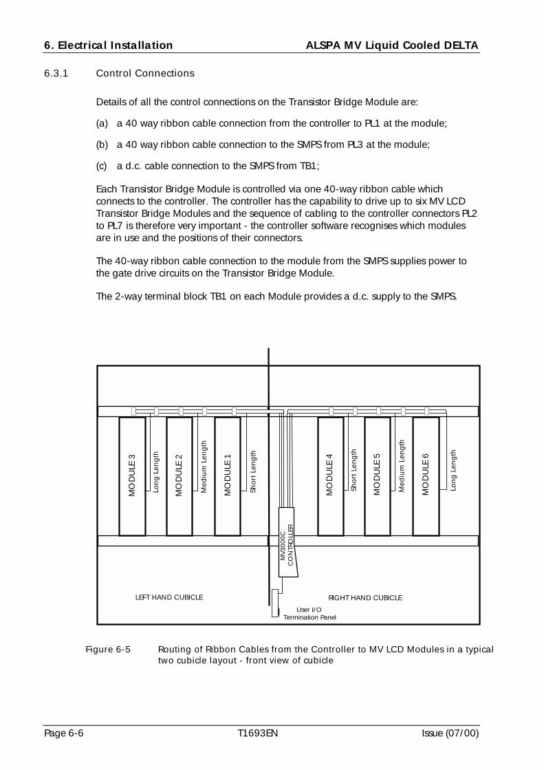
6. Electrical Installation ALSPA MV Liquid Cooled DELTA
Page 6-6 T1693EN Issue (07/00)
6.3.1 Control Connections
Details of all the control connections on the Transistor Bridge Module are:
(a) a 40 way ribbon cable connection from the controller to PL1 at the module;
(b) a 40 way ribbon cable connection to the SMPS from PL3 at the module;
(c) a d.c. cable connection to the SMPS from TB1;
Each Transistor Bridge Module is controlled via one 40-way ribbon cable whichconnects to the controller. The controller has the capability to drive up to six MV LCDTransistor Bridge Modules and the sequence of cabling to the controller connectors PL2to PL7 is therefore very important - the controller software recognises which modulesare in use and the positions of their connectors.
The 40-way ribbon cable connection to the module from the SMPS supplies power tothe gate drive circuits on the Transistor Bridge Module.
The 2-way terminal block TB1 on each Module provides a d.c. supply to the SMPS.
RIGHT HAND CUBICLELEFT HAND CUBICLE
Short
Len
gth
Med
ium
Len
gth
Lon
g L
eng
th
MO
DU
LE 3
MO
DU
LE 2
MO
DU
LE 1
MV3
000C
CO
NTR
OLL
ER
Lon
g L
eng
th
Med
ium
Len
gth
Short
Len
gth
MO
DU
LE 4
MO
DU
LE 5
MO
DU
LE 6
User I/OTermination Panel
Figure 6-5 Routing of Ribbon Cables from the Controller to MV LCD Modules in a typicaltwo cubicle layout - front view of cubicle
ALSPA MV Liquid Cooled DELTA 6. Electrical Installation
Issue (07/00) T1693EN Page 6-7
The ribbon cables for connections between the controller and the MV LCD Modules aresupplied in three lengths as follows:
(a) A Short Length ribbon of 2.12 m (6.96 ft) for connecting Modules 1 or 4;
(b) A Medium Length ribbon of 2.38 m (7.8 ft) for connecting Modules 2 or 5;
(c) A Long Length ribbon of 2.72 m (8.92 ft) for connecting Modules 3 or 6.
The ribbon cables are supplied in kit form, referenced MVC3004-4001 to 4003,suitable for connecting a number of modules to the controller and these are listed atTable 6-1. The cables must be connected in sequence starting with Plug PL2 at thecontroller being connected to MV LCD Module 1.
Figure 6-5 shows a simplified cubicle arrangement of the ribbon cables routedbetween the controller and the modules.
Table 6-1 Ribbon Cable Kits for Connections between Controller and MV LCDModules
For Connection toModule
Number(s)
Ribbon Cable Lengths
(Short, Medium or Long)
Ribbon Cable Kit Numbers
1 1 Short MVC3004-4001
1 & 2 1 Short & 1 Medium MVC3004-4002
1, 2 & 3 1 Short, 1 Medium & 1 Long MVC3004-4003
1, 2, 3 & 4 2 Short, 1 Medium & 1 Long MVC3004-4001 & MVC3004-4003
1, 2, 3, 4 & 5 2 Short, 2 Medium & 1 Long MVC3004-4002 & MVC3004-4003
1, 2, 3, 4, 5 & 6 2 Short, 2 Medium & 2 Long MVC3004-4003 & MVC3004-4003
6.3.2 Power Terminals for MVDL643 Transistor Bridge Module
Connections to the phase terminals, shown at Figure 6-4, are intended to be made bycables. Connections to the d.c. link terminals, DC+ and DC-, are intended to bemade by either cables or busbars.
Phase terminals, marked A, B and C, are each two M10 studs. D.C. link terminals,marked DC+ and DC-, are each two M10 studs at the bottom of the module. Theearth terminal, an M10 stud, is located on the lower left front face of the module.
The shrouds for power connections are attached by ‘press fit’ rivets as shown at Figure 6-6and must be fitted after the connections have been made.
6.3.3 AC Power Cables
A MV LCD module is designed for connection with cables, the maximum size of whichis 2 × 120 mm2 (250 mcm) - see 2.7.7 for cable details.
In multiple MV LCD module applications, sharing between the machine bridgemodules is achieved through the use of equal cable lengths which are each greaterthan 20 metres in length.
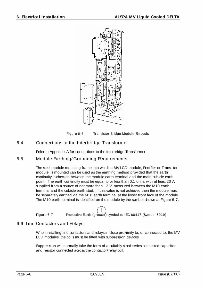
6. Electrical Installation ALSPA MV Liquid Cooled DELTA
Page 6-8 T1693EN Issue (07/00)
6.4 Connections to the Interbridge Transformer
Refer to Appendix A for connections to the Interbridge Transformer.
6.5 Module Earthing/Grounding Requirements
The steel module mounting frame into which a MV LCD module, Rectifier or Transistormodule, is mounted can be used as the earthing method provided that the earthcontinuity is checked between the module earth terminal and the main cubicle earthpoint. The earth continuity must be equal to or less than 0.1 ohm, with at least 20 Asupplied from a source of not more than 12 V, measured between the M10 earthterminal and the cubicle earth stud. If this value is not achieved then the module mustbe separately earthed via the M10 earth terminal at the lower front face of the module.The M10 earth terminal is identified on the module by the symbol shown at Figure 6-7.
Figure 6-7 Protective Earth (ground) symbol to IEC 60417 (Symbol 5019)
6.6 Line Contactors and Relays
When installing line contactors and relays in close proximity to, or connected to, the MVLCD modules, the coils must be fitted with suppression devices.
Suppression will normally take the form of a suitably sized series connected capacitorand resistor connected across the contactor/relay coil.
Figure 6-6 Transistor Bridge Module Shrouds
ALSPA MV Liquid Cooled DELTA 6. Electrical Installation
Issue (07/00) T1693EN Page 6-9
6.7 MV3000 Controller
All the connections at the MV3000 Controller for the MV LCD Transistor BridgeModules, the Rectifier Bridge Modules, the User I/O Termination Panel and the DriveData Manager (Keypad) are shown at Figure 6-8. Functions for PL12 connections atthe Controller, for the rectifier bridges, are listed at Table 6-2.
Connections at the Drive Data Manager (Keypad) are shown at Figure 6-9 and thefunctions listed at Table 6-3. Connections at the User I/O Termination Panel areshown at Figure 6-10 and the functions listed at Table 6-4.
The MV3000 Controller should be wired to the associated equipment in accordancewith the connection diagrams in Appendix A which show the connection arrangementsfor various configurations of network and machine bridges, the User I/O terminationpanel and the liquid cooling circuit.
There are particular rules which determine the position of each MV DELTA transistorbridge module in the mounting frames so that the controlling software correctlyrecognises the presence of the module in a particular position. The modules should beassembled in the mounting frames in a sequence from left to right (front view) withoutany spaces. The connection arrangement for the modules at the controller is shown inthe connection diagrams at Appendix A. The first module in the mounting frame isconnected to PL2 at the controller.
The configuration software does not recognise the position of a rectifier bridge modulein a mounting frame.
Table 6-2 Controller PL12 Connection Functions for Rectifier Modules
Terminal Number Function
1 NTC Temperature Monitor - Thermistor
2 NTC Temperature Monitor - Thermistor
3 Thermostat (24V = HEALTHY)
4 +24V
5 +24V
6 0V
7 +24V
8 Pre-charge Relay 24V
9 Pre-charge Acknowledge (24V = HEALTHY)
Table 6-3 Controller SK5 Connection Functions for Drive Data ManagerTM
Keypad
Terminal Number Function Comments
1 NC Not connected2 RS232 TX3 RS232 RX4 NC Not connected5 0V6 8V 8 V output from drive
7 & 8 Connected together9 PWM ON Indicates drive is active
Body EARTH Screen connection
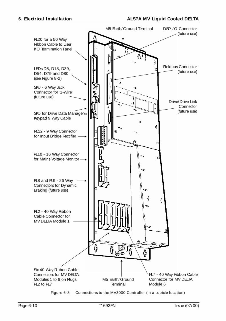
6. Electrical Installation ALSPA MV Liquid Cooled DELTA
Page 6-10 T1693EN Issue (07/00)
PL20 for a 50 WayRibbon Cable to UserI/O Termination Panel
SK5 for Drive Data ManagerKeypad 9 Way Cable
TM
SK6 - 6 Way JackConnector for '1-Wire'(future use)
PL12 - 9 Way Connectorfor Input Bridge Rectifier
PL10 - 16 Way Connectorfor Mains Voltage Monitor
PL8 and PL9 - 26 WayConnectors for DynamicBraking (future use)
PL2 - 40 Way RibbonCable Connector forMV DELTA Module 1
Six 40 Way Ribbon CableConnectors for MV DELTAModules 1 to 6 on PlugsPL2 to PL7
PL7 - 40 Way Ribbon CableConnector for MV DELTAModule 6
M5 Earth/GroundTerminal
M5 Earth/Ground Terminal
LEDs D5, D18, D39,D54, D79 and D80(see Figure 8-2)
Drive/Drive LinkConnector
(future use)
Fieldbus Connector(future use)
DSP I/O Connector(future use)
Figure 6-8 Connections to the MV3000 Controller (in a cubicle location)
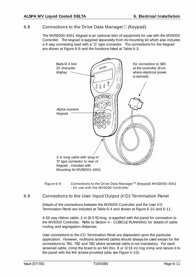
ALSPA MV Liquid Cooled DELTA 6. Electrical Installation
Issue (07/00) T1693EN Page 6-11
6.8 Connections to the Drive Data Manager (Keypad)
The MVS3000-4001 Keypad is an optional item of equipment for use with the MV3000Controller. The keypad is supplied separately from its mounting kit which also includesa 9 way connecting lead with a ‘D’ type connector. The connections for the Keypadare shown at Figure 6-9 and the functions listed at Table 6-3.
6.9 Connections to the User Input/Output (I/O) Termination Panel
Details of the connections between the MV3000 Controller and the User I/OTermination Panel are included at Table 6-4 and shown at Figure 6-10 and 6-11.
A 50 way ribbon cable, 2 m (6.5 ft) long, is supplied with the panel for connection tothe MV3000 Controller. Refer to Section 4 - CUBICLE PLANNING for details of cablerouting and segregation distances.
User connections to the I/O Termination Panel are dependent upon the particularapplication. However, multicore screened cables should always be used except for theconnections to TB1, TB2 and TB3 where screened cable is not mandatory. For eachscreened cable, crimp the braid to an M4 (No. 8 or 3/16 in) ring crimp and secure it tothe panel with the M4 screws provided (also see Figure 5-10).
Back-lit 4 line20 characterdisplay
Alpha-numericKeypad
3 m long cable with 'plug-in''D' type connector to rear ofKeypad - included withMounting Kit MVS3001-4001
For connection to SK5at the controller (fromwhere electrical poweris derived)
Figure 6-9 Connections to the Drive Data ManagerTM (Keypad) MVS3000-4001- for use with the MV3000 Controller
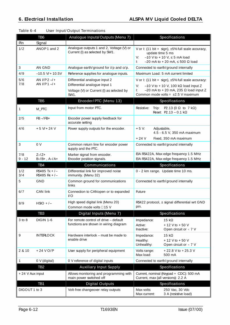
6. Electrical Installation ALSPA MV Liquid Cooled DELTA
Page 6-12 T1693EN Issue (07/00)
Table 6-4 User Input/Output Terminations
TB6 Analogue Inputs/Outputs (Menu 7) SpecificationsPin Signal1/2 ANOP 1 and 2 Analogue outputs 1 and 2, Voltage (V) or
Current (I) as selected by SW1.V or I: (11 bit + sign), ±5% full scale accuracy,
update time 5 msV: –10 V to +10 V, ≤ 5 mA loadI: –20 mA to +20 mA, ≤ 500 Ω load
3 AN GND Analogue earth/ground for i/p and o/p. Connected to earth/ground internally
4/9 –10.5 V/+10.5V Reference supplies for analogue inputs. Maximum Load: 5 mA current limited
5/6 AN I/P 2 –/+7/8 AN I/P 1 –/+
Differential analogue input 2Differential analogue input 1
Voltage (V) or Current (I) as selected bySW1.
V or I: (11 bit + sign), ±5% full scale accuracy:
V: –10 V to +10 V, 100 kΩ load input ZI: –20 mA to +20 mA, 235 Ω load input ZCommon mode volts = ±2.5 V maximum
TB5 Encoder/PTC (Menu 13) Specifications
1 M_PTC Input from motor PTC. Resistive: Trip: P2.13 (0 Ω to 7 kΩ) Reset: P2.13 – 0.1 kΩ
2/5 FB –/FB+ Encoder power supply feedback foraccurate setting
4/6 +5 V/+24 V Power supply outputs for the encoder. +5 V: Adjustable,4.5 - 6.5 V, 350 mA maximum
+24 V Fixed, 350 mA maximum
3 0 V Common return line for encoder powersupply and the PTC.
Connected to earth/ground internally
7/8 Z–/Z+9 - 12 B–/B+, A–/A+
Marker signal from encoder.Encoder position signals.
EIA RS422A, Max edge frequency 1.5 MHzEIA RS422A, Max edge frequency 1.5 MHz
TB4 Communications Specifications
1/2 RS485 Tx +/–3/4 RS485 Rx +/–
Differential link for improved noiseimmunity. (Menu 32)
0 - 2 km range. Update time 10 ms.
5 GND Common ground for communicationslinks
Connected to earth/ground internally
6/7 CAN link Connection to CANopen or to expandedI/O
Future
8/9 HSIO +/– High speed digital link (Menu 20)Common mode volts ≅ 15 V
RS422 protocol, ± signal differential wrt GNDpin.
TB3 Digital Inputs (Menu 7) Specifications
3 to 8 DIGIN 1-6 For remote control of drive – defaultfunctions are shown in wiring diagram
Impedance: 15 kΩActive: +12 V to +50 VInactive: Open circuit or < 7 V
9 INTERLOCK Hardware interlock – must be made toenable drive
Impedance: 15 kΩHealthy: +12 V to +50 VUnhealthy: Open circuit or < 7 V
2 & 10 +24 V O/P User supply for peripheral equipment Volts range: +22.8 V to +25.3 VMax load: 500 mA
1 0 V (digital) 0 V reference of digital inputs Connected to earth/ground internally
TB2 Auxiliary Input Supply Specifications
+24 V Aux input Allows monitoring and programming withmain power switched off
Current, nominal (Keypad + CDC): 500 mACurrent, max (all versions): 2.2 A
TB1 Digital Outputs Specifications
DIGOUT 1 to 3 Volt-free changeover relay outputs Max volts: 250 Vac, 30 VdcMax current: 3 A (resistive load)
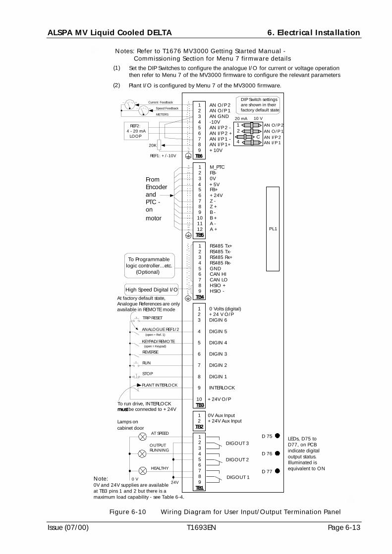
ALSPA MV Liquid Cooled DELTA 6. Electrical Installation
Issue (07/00) T1693EN Page 6-13
TB1TB1TB1TB1 9 8 DIGOUT 1 7 6 5 DIGOUT 2 4 3 2 DIGOUT 3 1
TB2TB2TB2TB2 2 +24V Aux Input 1 0V Aux Input
TB3TB3TB3TB3 10 +24V O/P
9 INTERLOCK
8 DIGIN 1
7 DIGIN 2
6 DIGIN 3
5 DIGIN 4
4 DIGIN 5
3 DIGIN 6 2 +24 V O/P 1 0 Volts (digital)
TB4TB4TB4TB4 9 HSIO - 8 HSIO + 7 CAN LO 6 CAN HI 5 GND 4 RS485 Rx- 3 RS485 Rx+ 2 RS485 Tx- 1 RS485 Tx+
TB5TB5TB5TB5 12 A + 11 A - 10 B + 9 B - 8 Z + 7 Z - 6 +24V 5 FB+4 +5V
3 0V 2 FB- 1 M_PTC
TB6TB6TB6TB6 9 +10V 8 AN I/P 1+ 7 AN I/P 1 - 6 AN I/P 2 + 5 AN I/P 2 - 4 -10V 3 AN GND 2 AN O/P 1 1 AN O/P 2
20K
TRIP RESET
0 V24V
REF1: +/-10V
High Speed Digital I/O
HEALTHY
AT SPEED
OUTPUTRUNNING
PLANT INTERLOCK
To run drive, INTERLOCKmustmustmustmustbe connected to +24V
Lamps oncabinet door
STOP
RUN
REVERSE
At factory default state,Analogue References are onlyavailable in REMOTE mode
To Programmablelogic controller...etc.
(Optional)
METERS
Speed Feedback
REF2:4 - 20 mA
LOOP AN O/P 1
KEYPAD/REMOTE(open = Keypad)
ANALOGUE REF1/2(open = Ref. 1)
PL1
Current Feedback
FromEncoderandPTC -onmotor
Note:0V and 24V supplies are availableat TB3 pins 1 and 2 but there is amaximum load capability - see Table 6-4.
AN O/P 2
20 mA 10 V
AN I/P 1 AN I/P 2
43 C
12
DIP Switch settingsare shown in theirfactory default state
(2) Plant I/O is configured by Menu 7 of the MV3000 firmware.
(1) Set the DIP Switches to configure the analogue I/O for current or voltage operationthen refer to Menu 7 of the MV3000 firmware to configure the relevant parameters
Notes: Refer to T1676 MV3000 Getting Started Manual -Commissioning Section for Menu 7 firmware details
D 75
D 76
D 77
LEDs, D75 toD77, on PCBindicate digitaloutput status.Illuminated isequivalent to ON
Figure 6-10 Wiring Diagram for User Input/Output Termination Panel
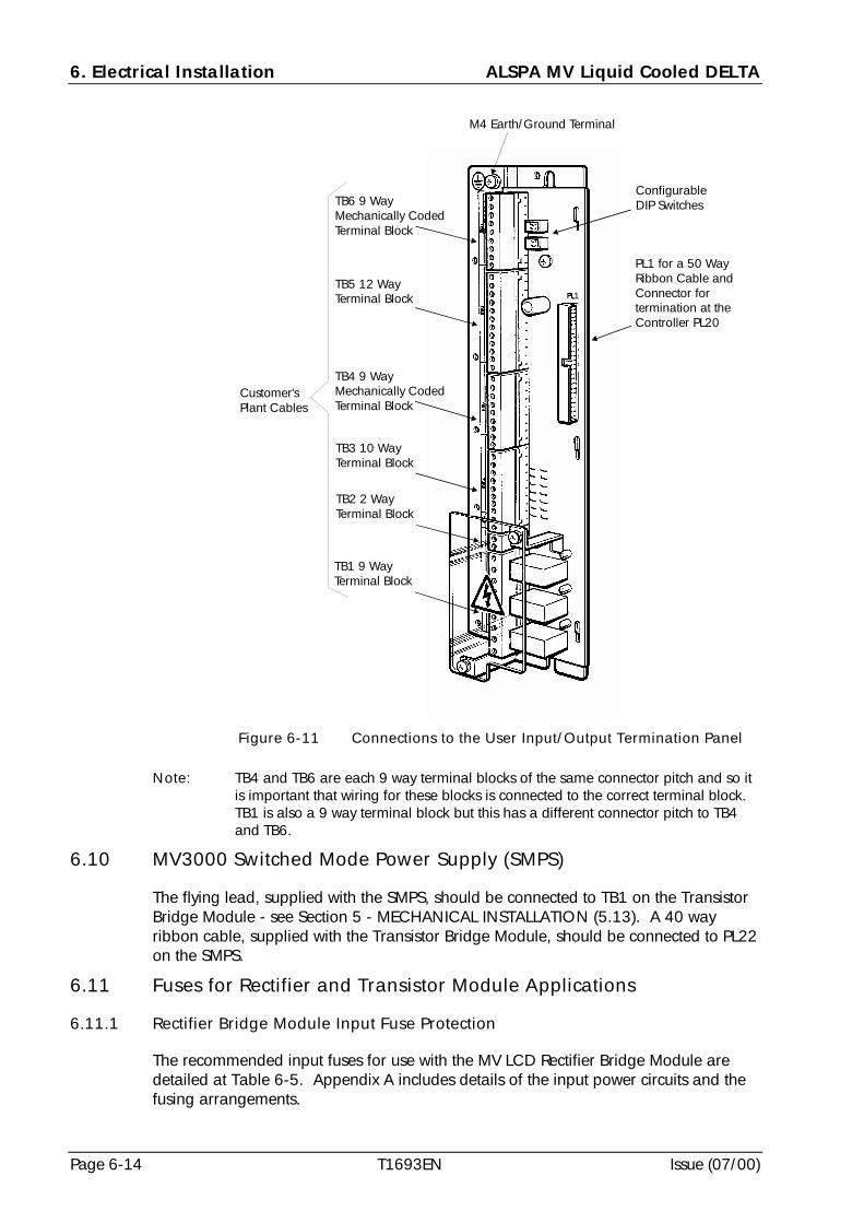
6. Electrical Installation ALSPA MV Liquid Cooled DELTA
Page 6-14 T1693EN Issue (07/00)
Note: TB4 and TB6 are each 9 way terminal blocks of the same connector pitch and so itis important that wiring for these blocks is connected to the correct terminal block.TB1 is also a 9 way terminal block but this has a different connector pitch to TB4and TB6.
6.10 MV3000 Switched Mode Power Supply (SMPS)
The flying lead, supplied with the SMPS, should be connected to TB1 on the TransistorBridge Module - see Section 5 - MECHANICAL INSTALLATION (5.13). A 40 wayribbon cable, supplied with the Transistor Bridge Module, should be connected to PL22on the SMPS.
6.11 Fuses for Rectifier and Transistor Module Applications
6.11.1 Rectifier Bridge Module Input Fuse Protection
The recommended input fuses for use with the MV LCD Rectifier Bridge Module aredetailed at Table 6-5. Appendix A includes details of the input power circuits and thefusing arrangements.
M4 Earth/Ground Terminal
TB6 9 WayMechanically CodedTerminal Block
TB5 12 WayTerminal Block
ConfigurableDIP Switches
TB4 9 WayMechanically CodedTerminal Block
TB3 10 WayTerminal Block
TB2 2 WayTerminal Block
TB1 9 WayTerminal Block
Customer'sPlant Cables
PL1 for a 50 WayRibbon Cable andConnector fortermination at theController PL20
1
Figure 6-11 Connections to the User Input/Output Termination Panel
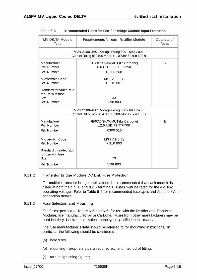
ALSPA MV Liquid Cooled DELTA 6. Electrical Installation
Issue (07/00) T1693EN Page 6-15
Table 6-5 Recommended Fuses for Rectifier Bridge Module Input Protection
MV DELTA ModuleType
Requirements for each Rectifier Module Quantity offuses
MVRL2100-4601 Voltage Rating 500 - 690 V a.c.Current Rating of 2100 A d.c. + 10% for 60 s in 600 s
ManufacturerPart Number
Ref. Number
Microswitch CodeRef. Number
Standard threaded studfor use with fuseSizeRef. Number
FERRAZ SHAWMUT (Le Carbone)6.6 URD 233 TTF 1250
D 300 268
MS 3V 2-5 BSH 310 001
33V 98 803
6
MVRL2100-4601 Voltage Rating 500 - 690 V a.c.Current Rating of 920 A d.c. + 100% for 12 s in 180 s
ManufacturerPart Number
Ref. Number
Microswitch CodeRef. Number
Standard threaded studfor use with fuseSize
Ref. Number
FERRAZ SHAWMUT (Le Carbone)12.5 URD 73 TTF 700
R 300 510
MS 7V 1-5 BSK 310 003
73
V 98 803
6
6.11.2 Transistor Bridge Module DC Link Fuse Protection
For multiple transistor bridge applications, it is recommended that each module isfused at both the d.c. + and d.c. - terminals. Fuses must be rated for the d.c. linkoperating voltage. Refer to Table 6-6 for recommended fuse types and Appendix A forconnection details.
6.11.3 Fuse Selection and Mounting
The fuses specified at Tables 6-5 and 6-6, for use with the Rectifier and TransistorModules, are manufactured by Le Carbone. Fuses from other manufacturers may beused but they should be equivalent to the types specified in this manual.
The fuse manufacturer’s data should be referred to for mounting instructions. Inparticular the following should be considered:
(a) hole sizes;
(b) mounting - proprietary parts required etc. and method of fitting;
(c) torque tightening figures;
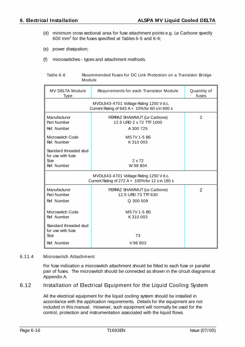
6. Electrical Installation ALSPA MV Liquid Cooled DELTA
Page 6-16 T1693EN Issue (07/00)
(d) minimum cross sectional area for fuse attachment points e.g. Le Carbone specify600 mm2 for the fuses specified at Tables 6-5 and 6-6;
(e) power dissipation;
(f) microswitches - types and attachment methods.
Table 6-6 Recommended Fuses for DC Link Protection on a Transistor BridgeModule
MV DELTA ModuleType
Requirements for each Transistor Module Quantity offuses
MVDL643-4701 Voltage Rating 1250 V d.c.Current Rating of 643 A + 10% for 60 s in 600 s
ManufacturerPart Number
Ref. Number
Microswitch CodeRef. Number
Standard threaded studfor use with fuseSizeRef. Number
FERRAZ SHAWMUT (Le Carbone)12.5 URD 2 x 72 TTF 1000
A 300 725
MS 7V 1-5 BSK 310 003
2 x 72W 98 804
2
MVDL643-4701 Voltage Rating 1250 V d.c.Current Rating of 272 A + 100% for 12 s in 180 s
ManufacturerPart Number
Ref. Number
Microswitch CodeRef. Number
Standard threaded studfor use with fuseSize
Ref. Number
FERRAZ SHAWMUT (Le Carbone)12.5 URD 73 TTF 630
Q 300 509
MS 7V 1-5 BSK 310 003
73
V 98 803
2
6.11.4 Microswitch Attachment
For fuse indication a microswitch attachment should be fitted to each fuse or parallelpair of fuses. The microswitch should be connected as shown in the circuit diagrams atAppendix A.
6.12 Installation of Electrical Equipment for the Liquid Cooling System
All the electrical equipment for the liquid cooling system should be installed inaccordance with the application requirements. Details for the equipment are notincluded in this manual. However, such equipment will normally be used for thecontrol, protection and instrumentation associated with the liquid flows.
ALSPA MV Liquid Cooled DELTA 7. Commissioning
Issue (07/00) T1693EN Page 7-1
7. Commissioning
7.1 Introduction
The commissioning procedure for each drive with MV Liquid Cooled DELTA (MV LCD)modules will vary for each application; such details are not included in this manual.However, reference should be made to the MV3000 Getting Started Manual T1676which does include general guidance for commissioning. When the equipment hasbeen designed and built for a particular application by a System Integrator then it isimportant, for the safety of personnel and equipment, that all commissioninginstructions prepared by the Integrator include the following details:
(a) warnings and cautions as necessary;
(b) mechanical checks;
(c) electrical checks;
(d) cooling system checks - internal and external to the enclosure.
WARNINGS! Exposed High Voltages
Enclose all items exposing high voltage before the equipment isenergised.
! Energy Discharge
Wait at least 5 minutes after isolating supplies and check that voltagebetween DC+ and DC- has reduced to a safe level before working onthis equipment.
! Multiple Circuits
This equipment may be connected to more than one live circuit.Disconnect all supplies before working on the equipment.
! High Leakage CurrentThis equipment and the driven motors(s) must be earthed (grounded).
! Radio TransmittersDo not use mobile phones or walkie talkies within 2 metres (6 feet) ofthe equipment.
! Health Hazards of Liquid Coolants
The coolant used in this equipment may be hazardous to health if notstored, handled and disposed of in accordance with the manufacturer’sinstructions.
! High TemperaturesSurfaces on the following items can reach high temperatures:
• reactors and transformers
• cables
• coolant pipes and couplings.
7. Commissioning ALSPA MV Liquid Cooled DELTA
Page 7-2 T1693EN Issue (07/00)
7.2 Pre-commissioning Checks
7.2.1 Mechanical Checks
The pre-commissioning mechanical checks now outlined apply to MV LCD equipmenthoused in a cubicle and also, where appropriate, to MV LCD modules supplied loose.The checks outlined include those for the cooling system within the cubicle and alsoexternal to it e.g. checks to ensure mechanical integrity of the piping. Check that:
(a) each module is of the same type and voltage grade for the application;
(b) the modules have been correctly assembled in the appropriate mounting frames inaccordance with the instructions in Sections 5 and 6 of this manual;
(c) the modules have been assembled in the correct sequence i.e. no intermediatepositions left empty;
(d) there is adequate clearance around the controller within the cubicle for ventilation;
(e) there is adequate clearance around the cubicle for ventilation, and that theventilation louvres are not covered or blocked;
(f) all piping from a liquid cooled module to the cubicle mounted manifold isinstalled in accordance with the guidance at Section 5 - MECHANICALINSTALLATION;
(g) all piping from the cubicle/enclosure manifold to the external cooling system isdesigned and installed in accordance with guidance at Section 3 - COOLINGSYSTEM DESIGN.
Note: Check that the material compatibility rules have been followed in the coolingsystem.
7.2.2 Electrical Checks
When mechanical checks have been completed, including all piping checks, all theelectrical equipment, specific to the particular application, should be checked forcorrect installation, wiring and earthing. The latter particularly to ensure safetyearthing and protection against high leakage currents. These checks apply to all thefollowing equipment:
(a) control equipment;
(b) protection equipment;
(c) instrumentation;
(d) associated motors.
Some specific checks are also recommended. Check that:
(1) the SMPS is compatible with the module voltage grade;
(2) the drive has been installed in accordance with the instructions in Sections 5 and 6 ofthis manual - particularly that shrouds are fitted;
ALSPA MV Liquid Cooled DELTA 7. Commissioning
Issue (07/00) T1693EN Page 7-3
(3) all configurable components are correctly set e.g. the DIP switches on the User I/OTermination Panel;
(4) all interlocking circuits are correctly connected;
(5) there are no earth (ground) faults on the motor(s);
(6) it is safe to perform the commissioning procedure, which will involve energisingand rotating the motor;
(7) you are familiar with the controls for the MV3000 Controller and use of the DriveData Manager (Keypad);
(8) all electrical supplies are available and within specification.
When all these checks have been carried out refer to 7.3 for details of the InsulationTests.
7.3 Insulation Tests
When the pre-commissioning checks have been completed it is recommended thatinsulation tests be carried out, prior to the equipment being commissioned, to checkthat cables have not been damaged during installation and that the equipment iscorrectly bonded for earthing purposes. These tests will vary in detail for eachapplication, particularly the tests which are carried out at a cubicle level, and thereforeonly general guidance is included.
For ease of testing it is recommended that the MV LCD equipment be considered infour groups. The tests are detailed for each group with all the test conditions applicableto other groups also being specified. The equipment performance should be checkedafter all the insulation tests have been completed to ensure that no component damagehas occurred.
7.3.1 Equipment Groups
The groups of equipment are:
(a) Group A - the main power circuit;
(b) Group B - the auxiliary circuits;
(c) Group C - the low voltage circuits;
(d) Group D - the ‘earthed’ parts.
7.3.1.1 Group A - The Main Power Circuit
This circuit comprises:
(a) main fuses;
(b) main isolator;
(c) module power connections i.e. d.c. and a.c. cabling/busbars but not the modulesthemselves;
(d) output reactors.
7. Commissioning ALSPA MV Liquid Cooled DELTA
Page 7-4 T1693EN Issue (07/00)
Note: Motor contactors for a MV LCD module, which are application dependent,would also be considered a part of the main power circuit for purposes ofinsulation testing.
7.3.1.2 Group B - The Auxiliary Circuits
These circuits, which are generally application dependent, comprise:
(a) main 3 phase supply (e.g. 440 V a.c.) and all items connected to it e.g. supplymonitoring;
(b) single phase control supplies and all items connected to it e.g. fans, pumps,heaters etc.
7.3.1.3 Group C - The Low Voltage Circuits
The low voltage circuits are generally application dependent. However, the followingitems of equipment would normally be expected as part of the low voltage circuits:
(a) all circuits connected to control circuit components e.g. contactor coils, relaycircuits, earth leakage CT etc;
(b) all circuits connected to the User I/O Termination Panel.
7.3.1.4 Group D - The ‘Earthed/Grounded’ Parts
These circuits comprise the cubicle structure, earth/ground bar, signal ground andscreen bars, and earthed metalwork in general, including component mounting/containers.
7.3.2 Preliminary Checks Prior to Carrying Out Insulation Voltage Tests
Before any of the following insulation voltage tests are carried out proceed as follows:
(a) join together all the components in each of the three groups A to C;
(b) check with an Avometer or Digital Volt Meter, on the high resistance range, thateach of the above groups is isolated from each other and from earth;
(c) ensure that the MV LCD modules are completely disconnected.
Proceed to carry out the following insulation tests in the order specified.
7.3.3 Insulation Tests for each Group
The insulation tests, and the test procedures, for each of these groups of equipment fora MV LCD system are detailed at Table 7-1.
When Insulation Voltage Tests have been carried out remove all the wires which wereput in place for the insulation testing and re-connect the equipment in accordance withthe circuit diagrams.
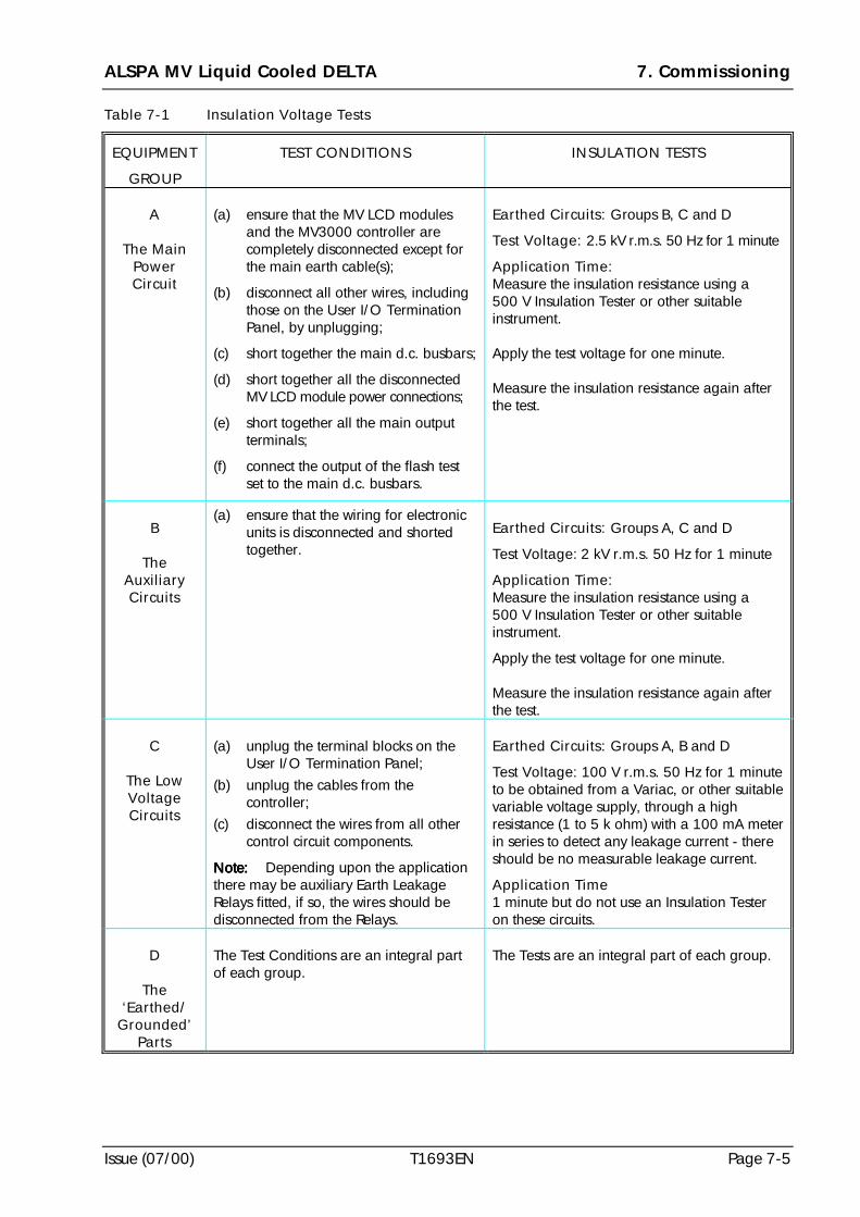
ALSPA MV Liquid Cooled DELTA 7. Commissioning
Issue (07/00) T1693EN Page 7-5
Table 7-1 Insulation Voltage Tests
EQUIPMENT
GROUP
TEST CONDITIONS INSULATION TESTS
A
The MainPowerCircuit
(a) ensure that the MV LCD modulesand the MV3000 controller arecompletely disconnected except forthe main earth cable(s);
(b) disconnect all other wires, includingthose on the User I/O TerminationPanel, by unplugging;
(c) short together the main d.c. busbars;
(d) short together all the disconnectedMV LCD module power connections;
(e) short together all the main outputterminals;
(f) connect the output of the flash testset to the main d.c. busbars.
Earthed Circuits: Groups B, C and D
Test Voltage: 2.5 kV r.m.s. 50 Hz for 1 minute
Application Time:Measure the insulation resistance using a500 V Insulation Tester or other suitableinstrument.
Apply the test voltage for one minute.
Measure the insulation resistance again afterthe test.
B
TheAuxiliaryCircuits
(a) ensure that the wiring for electronicunits is disconnected and shortedtogether.
Earthed Circuits: Groups A, C and D
Test Voltage: 2 kV r.m.s. 50 Hz for 1 minute
Application Time:Measure the insulation resistance using a500 V Insulation Tester or other suitableinstrument.
Apply the test voltage for one minute.
Measure the insulation resistance again afterthe test.
C
The LowVoltageCircuits
(a) unplug the terminal blocks on theUser I/O Termination Panel;
(b) unplug the cables from thecontroller;
(c) disconnect the wires from all othercontrol circuit components.
Note:Note:Note:Note: Depending upon the applicationthere may be auxiliary Earth LeakageRelays fitted, if so, the wires should bedisconnected from the Relays.
Earthed Circuits: Groups A, B and D
Test Voltage: 100 V r.m.s. 50 Hz for 1 minuteto be obtained from a Variac, or other suitablevariable voltage supply, through a highresistance (1 to 5 k ohm) with a 100 mA meterin series to detect any leakage current - thereshould be no measurable leakage current.
Application Time1 minute but do not use an Insulation Testeron these circuits.
D
The‘Earthed/
Grounded’Parts
The Test Conditions are an integral partof each group.
The Tests are an integral part of each group.
7. Commissioning ALSPA MV Liquid Cooled DELTA
Page 7-6 T1693EN Issue (07/00)
7.4 Preparation of the Cooling System
7.4.1 Initial Checks prior to Coolant Loading
To ensure cooling efficiency for the power devices in the MV LCD modules carry out thefollowing checks before loading the coolant into the cooling system.
Check that:
(a) all modules have been assembled in the appropriate mounting frame;
(b) all cooling system connections are correctly made and the external cooling systemhas been appropriately designed (see Section 3 - COOLING SYSTEM DESIGN);
(c) the FLOW and RETURN pipes are in correct positions at the module;
(d) all flexible pipes are securely fastened within the cubicle/enclosure;
(e) all materials used in the external cooling system are compatible with the materialsin the module cooling path (see Section 2 - SPECIFICATION);
(f) the coolant to be used is of a recommended type or a compatible alternative;
(g) the coolant mixture and concentration meet required temperature range;
(h) the end caps from all couplings on the flexible pipes have been safely stored forfuture use during re-commissioning or maintenance.
7.4.2 Initial Tests prior to Running the Cooling System
Carry out the following tests before running the cooling system:
(a) flush the system with de-mineralised water to remove any debris; clean strainer;
(b) a pressure test, pneumatic or hydrostatic, to ensure the cooling system withstandsworking pressure – a hydrostatic test may use the intended coolant (see 7.5).
7.5 Filling the Cooling System
7.5.1 Precautions
Precautions, which should be observed when using a coolant, are:
(a) only use coolant with corrosion inhibitors;
(b) read the manufacturer’s Safety Instructions before using the coolant;
(c) handle, use, store and dispose of coolant in accordance with the manufacturer’sinstructions - use protective gloves when handling the coolant;
(d) do not mix coolants from different manufacturers or different types from the samemanufacturer.
7.5.2 Procedure
The procedure for filling the cooling system will depend on the specific application.The requirements will vary for each application but will normally include the followingstages:
ALSPA MV Liquid Cooled DELTA 7. Commissioning
Issue (07/00) T1693EN Page 7-7
(a) calculate the amount of coolant mixture required for a complete cooling system -allow for the volume of coolant in modules, all pipework, pumps, manifolds andthe header tank;
(b) determine the concentration required for a recommended coolant mixture basedon the lowest temperatures likely to be experienced and the details at Section 3 -COOLING SYSTEM DESIGN – for recommended types and manufacturers;
Note: As the percentage of ethylene glycol within a coolant mixture increases,the efficiency of the coolant to remove the heat from the modulereduces slightly. Concentrations above 50% offer no further protectionagainst low temperatures and above 75% provide less lowtemperature protection. A minimum concentration of 33% must beincluded to ensure adequate corrosion protection.
(c) prepare the required amount of a coolant mixture, to the required concentration,to meet the requirements of the cooling specification and with an allowance forsome spare concentrate mixture to be stored for ‘top up’ purposes;
(d) fill the cooling system either via the header tank or through a suitable fillinglocation if a closed system is used;
(e) when the system has been filled, carefully vent all air as follows:
(1) bleed each module at its top air vent valve (see Figure 5-15), with a 5 mm(0.2 in) square key, do not fully remove the bleed screw from thevalve;
(2) ensure that coolant does not ‘flood out’;
(3) when all air has been purged, tightly close the bleed screw.
(f) top up the system, if necessary;
(g) carry out a visual check for coolant leaks in the system;
(h) record details of coolant type and loading date on plant records (see Figure 8-3).
7.6 Running the Coolant Pump only
When the cooling system has been filled with the specified coolant mixture run thecoolant pump to check the integrity of the cooling system and to trap any foreignbodies from the system in a strainer. Proceed as follows:
(a) start up the coolant pump and run for one hour at working pressure;
(b) visually check the cooling system for coolant leaks;
(c) after one hour switch off the pump;
(d) isolate the strainer by closing the ball valves on each side of it;
(e) remove the strainer from the system and clean it of any foreign bodies;
(f) replace the strainer;
(g) open the ball valves;
(h) now proceed with checks for the instrumentation and controls.
7. Commissioning ALSPA MV Liquid Cooled DELTA
Page 7-8 T1693EN Issue (07/00)
7.7 Checks for Instrumentation and Controls
Checks for the control, protection and instrumentation included for each cooling systemdesign may vary and these will normally be included at the system integration stage.They should be checked prior to the complete drive system being commissioned.
(a) start up the coolant pump;
(b) start up the heat exchanger fan and check for fan operation;
(c) carry out another visual check for coolant leaks during operation of coolant pump;
(d) if flow meters are fitted check that the flow rate meets the specification at Section 3- COOLING SYSTEM DESIGN;
(e) check all feedback signals from the header tank if fitted - this should include a tripsignal for the condition when the coolant level is too low;
(f) check for interlocking with other aspects of a drive, for example:
(1) when coolant flow is stopped;
(2) co-ordination of FAN ON and PUMP ON;
(g) proceed to commission the drive in accordance with MV3000 Getting StartedManual T1676 carrying out coolant temperature checks at 7.9 during commissioning.
7.8 Commissioning
After the pre-commissioning checks, the insulation tests and preparation of the LiquidCooled system have been carried out as described in this section proceed tocommission the full drive equipment. The commissioning should be in accordance withinstructions in the MV3000 Getting Started Manual T1676 and, when applicable, theinstructions prepared by a System Integrator. Details for customising the MV3000Controller parameters for specific applications i.e. application programming, are alsoin the T1676 Manual.
7.9 Coolant Temperature Checks During Commissioning
The commissioning procedures, which are defined in the MV3000 Getting StartedManual T1676, must be followed.
If the external coolant temperature can be measured this can be compared with thetransistor bridge temperatures. Prior to running the bridge, its temperature, which isindicated by the feedback signals to the controller, via parameter P11.05 for theMachine (Output) Bridge 1, for example, can be compared against the coolant flowtemperature and should be of a similar value.
Run the transistor bridge and monitor the bridge temperatures via the feedback signalsto the controller. Check that there are no significant variations between thetemperatures of the bridges of different modules. If there is a variation, check the flowand return temperatures for the coolant at each module and compare with othermodules. A variation of temperature, between the modules, may arise because of anunequal coolant flow and this should be investigated and corrected.
ALSPA MV Liquid Cooled DELTA 8. Maintenance
Issue (07/00) T1693EN Page 8-1
8. Maintenance
CAUTIONAny metallic item touching the coolant duct or the aluminium heatsink MUSTBE STAINLESS STEEL - note particularly when fitting screws.
8.1 Introduction
This section describes maintenance for the ALSPA MV Liquid Cooled DELTA (MV LCD)modules and the MV3000 Controller in a MV3000 Liquid Cooled DELTA System.
No component maintenance is described for the module or the controller. If eitherproduct requires component maintenance a request for assistance should be made toan ALSTOM Service Centre via the appropriate national address at the back of thismanual.
Some users may have the facilities, the skill and the appropriate lifting equipment toenable a replacement MV LCD module to be fitted should this become necessary. Thissection of the manual therefore includes sufficient detail to enable such users to removeand refit a module.
Because of the technology used in the MV LCD module there is a requirement forperiodic maintenance to be carried out and this is also detailed in this section of themanual.
Throughout this section of the manual reference to a MV LCD Module should be readas applying to either a Rectifier Module or a Transistor Module unless a type of moduleis specifically stated.
8.2 Special Tools, Equipment and Materials
8.2.1 For the MV LCD Module (Transistor or Rectifier Bridge)
Special tools and equipment for work with the MV LCD Module are:
(a) a torque screwdriver or torque wrench for M10 size;
(b) a PZ3 screwdriver for M6 Pozidrive screws;
(c) socket head key (‘radiator bleed’ type) 5 mm (0.2 in) square across flats;
WARNING! Radio Transmitters
Do not use mobile phones or walkie talkies within 2 metres (6 feet) of theequipment.
! Health Hazards of Liquid Coolants
The coolant used in this equipment may be hazardous to health if notstored, handled and disposed of in accordance with the manufacturer’sinstructions.
8. Maintenance ALSPA MV Liquid Cooled DELTA
Page 8-2 T1693EN Issue (07/00)
(d) small container for a few millilitres of coolant;
(e) larger container (e.g. a bucket) for at least 1.75 litres (0.38 UK gallon or 0.46 USgallon) of coolant;
(f) a suitable container for storage of coolant;
(g) 1 spare hose coupling Staubli Unimation Part RMI16 Type N007117 96-SKTsocket (ALSTOM Part Number 47307/100) attached to a suitable length (e.g.1 metre or 3 ft) of hose (for draining a module into a large container);
(h) suitable ‘soak-up’ material (e.g. cloths, rags, absorbent paper) for the surpluscoolant;
(i) two pairs of gloves - one pair for handling the module and the coolant hoses(when uncoupling) and a waterproof pair for protection when handling thecoolant;
(j) a crane suitably rated for lifting the MV LCD module (see Section 5 -MECHANICAL INSTALLATION).
8.2.2 For the MV3000 Controller
The special tools and equipment for work with the MV3000 Controller are:
(a) a torque screwdriver or torque wrench for M5 size;
(b) a PZ screwdriver for M3 and M4 Pozidrive screws.
8.2.3 For Packing a MV LCD Module or a MV3000 Controller
Appropriate tools, equipment and materials are required for the preparation of aMV LCD Module and/or a MV3000 Controller for transportation including:
(a) tools and equipment for the MV LCD Module, to:
(1) lift the module;
(2) wrap the module in a protective layer of paper packing/wrapping;
(3) seal the module in an anti static bag;
(4) evacuate the air from the bag prior to final sealing;
(5) weigh the module;
(6) seal and label the packing crate.
(b) tools and equipment for the MV3000 Controller, to:
(1) seal the module in an anti static bag;
(2) evacuate the air from the bag prior to final sealing;
(3) weigh the controller;
(4) seal and label the packing box.
ALSPA MV Liquid Cooled DELTA 8. Maintenance
Issue (07/00) T1693EN Page 8-3
(c) packing materials for the MV LCD Module including:
(1) a waterproof anti static bag size 1500 mm long x 730 mm wide x 840 mmhigh (≈ 60 in x 29 in x 33 in);
(2) 300 g (≈ 11 oz) of desiccant for moisture protection inside the bag;
(3) a supply of paper packing/wrapping suitable for the protection of a moduleduring transit and for wrapping the packing crate;
(4) a tri-wall packing case, with wooden pallet, of internal dimensions 1370 mmwide x 600 mm deep x 350 mm high (≈ 54 in x 23.5 in x 14 in) which iscapable of withstanding the conditions of transportation.
(d) packing materials for the MV3000 Controller including:
(1) a gusseted waterproof anti static bag size 508 mm long x 610 mm wide(≈ 20 in x 24 in) for the controller;
(2) 10 g (≈ 0.5 oz) of desiccant for moisture protection inside the bag;
(3) suitable polystyrene materials for retaining the controller in position in apacking box;
(4) a suitable packing box of internal dimensions 604 mm wide x 318 mm deepx 168 mm high (≈ 24 in x 13 in x 7 in) which is capable of withstanding theconditions of transportation.
8.3 Disconnection of Electrical Supplies from a MV LCD Module
WARNINGS! Energy Discharge
Wait at least 5 minutes after isolating supplies and check that voltagebetween DC+ and DC- has reduced to a safe level before working on thisequipment.
! Multiple Circuits
This equipment may be connected to more than one live circuit.Disconnect all supplies before working on the equipment.
! High Leakage Current
This equipment and the driven motor(s) must be earthed (grounded).
! High Temperatures
Surfaces on the following items can reach high temperatures:
• reactors and transformers
• cables
• coolant pipes and couplings.
8. Maintenance ALSPA MV Liquid Cooled DELTA
Page 8-4 T1693EN Issue (07/00)
8.3.1 Preliminary Checks
Before commencing any work on a MV LCD module check that:
(a) above WARNINGS have been followed;
(b) all electrical power is switched off to the cubicle/enclosure housing the moduleand any interlocked circuits from other sources which feed into thatcubicle/enclosure - wait at least 5 minutes after isolating supplies;
(c) the cooling system has been switched off i.e. no coolant is flowing;
(d) instructions for the safe handling, use, storage and disposal of the coolant,supplied by the manufacturer, have been read and followed;
(e) a suitably rated crane is available - see Section 5 - MECHANICAL INSTALLATION;
(f) two people are available for use of the crane and handling of the module.
8.3.2 Recommended Procedure for Disconnection of Wiring from a Module
Remove all electrical wiring from either a rectifier module or a transistor module in thefollowing sequence:
(a) remove the terminal shrouds;
(b) disconnect all power cables, a.c. and d.c., noting their connection positions;
(c) disconnect all control wiring from terminal boards and/or ribbon connections;
(d) if disconnection is from a transistor module remove the SMPS - see 8.12.
8.4 Removal of a MV LCD Module from a Cubicle
CAUTION
The modules are delicate and vulnerable to damage - handle carefully.
Only lift or move them by use of the lifting point.
Lay them down on the plain left-hand face when not fitted in a frame.
Do not leave modules unsupported in the upright position.
WARNINGHeavy WeightsItems marked with weights greater than 20 kg should only be moved withlifting apparatus.
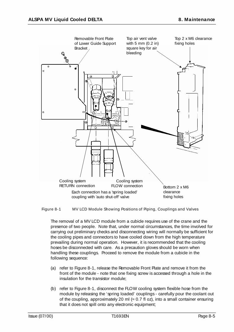
ALSPA MV Liquid Cooled DELTA 8. Maintenance
Issue (07/00) T1693EN Page 8-5
The removal of a MV LCD module from a cubicle requires use of the crane and thepresence of two people. Note that, under normal circumstances, the time involved forcarrying out preliminary checks and disconnecting wiring will normally be sufficient forthe cooling pipes and connectors to have cooled down from the high temperatureprevailing during normal operation. However, it is recommended that the coolinghoses be disconnected with care. As a precaution gloves should be worn whenhandling these couplings. Proceed to remove the module from a cubicle in thefollowing sequence:
(a) refer to Figure 8-1, release the Removable Front Plate and remove it from thefront of the module - note that one fixing screw is accessed through a hole in theinsulation for the transistor module;
(b) refer to Figure 8-1, disconnect the FLOW cooling system flexible hose from themodule by releasing the ‘spring loaded’ couplings - carefully pour the coolant outof the coupling, approximately 20 ml (≈ 0.7 fl oz), into a small container ensuringthat it does not spill onto any electronic equipment;
Top air vent valvewith 5 mm (0.2 in)square key for airbleeding
Removable Front Plateof Lower Guide SupportBracket
Top 2 x M6 clearancefixing holes
Bottom 2 x M6clearancefixing holes
Cooling systemconnectionFLOW
Cooling systemconnectionRETURN
Each connection has a 'spring loaded'coupling with 'auto shut-off' valve
Figure 8-1 MV LCD Module Showing Positions of Piping, Couplings and Valves
8. Maintenance ALSPA MV Liquid Cooled DELTA
Page 8-6 T1693EN Issue (07/00)
(c) refer to Figure 8-1, disconnect the RETURN cooling system flexible hose from themodule by releasing the ‘spring loaded’ couplings - carefully pour the coolant outof the coupling, approximately 20 ml (≈ 0.7 fl oz), into a small container ensuringthat it does not spill onto any electronic equipment;
(d) release the module from its frame by undoing the four M6 Pozi-head fixingscrews, spring and plain washers - two sets at the top and two at the bottom;
(e) withdraw the module until it reaches the STOP SCREW and then attach the craneshackle to the lifting hole in the top of the module (see Figures 5-4 and 5-5);
(f) take up the weight of the module on the crane and carefully withdraw the modulefrom its frame, over the STOP SCREW (at the bottom right-hand guide);
(g) with the crane taking the weight of the module, completely withdraw the modulefrom its frame;
(h) with the module hanging on the crane and steadied in its vertical position by oneperson, drain the coolant out of the module into a suitable large container (e.g. abucket) - drain by attaching the spare hose to the ‘spring loaded’ coupling for theFLOW hose on the module and then attaching it to the RETURN coupling to drainboth sides of the module;
(i) when all the coolant has been drained from the module remove the spare hoseand coupling and move the module into a safe position with its left hand side(when viewed from the front) laid on a flat surface;
(j) check the drained coolant for any solid particles and remove them, by filtration ifnecessary;
(k) retain the cleaned coolant for subsequent return to the cooling system for usewhen a new module is fitted;
(l) take the ‘end caps’ out of store and fit them to all couplings.
8.5 Transporting a MV LCD Module
CAUTIONS
! DO NOT TRANSPORT the module at any time with the coolant inside it -there is a risk of damage due to differential expansion.
! DO NOT FLUSH the module after it has been drained - there is a risk ofdamage due to corrosion from the use of ordinary water.
8.5.1 Preparation of the MV LCD Module for Shipping
If it becomes necessary for a MV LCD module (transistor or rectifier bridge) to betaken out of service and transported to an ALSTOM factory or service centre it is mostimportant that the module is prepared for shipping in the following way with strictadherence to the above cautions:
(a) remove the module from the cubicle as described at 8.4;
(b) check that the module has been drained;
ALSPA MV Liquid Cooled DELTA 8. Maintenance
Issue (07/00) T1693EN Page 8-7
(c) check that the air vent valve is sealed;
(d) check that the ‘end caps’ have been fitted to all couplings;
(e) prepare for shipping.
8.5.2 Packing a MV LCD Module for Shipping
When packing a MV LCD Module for shipping it is preferable to use the originalpacking material. However, if that packing material is not available, the moduleshould be packed as now generally described. The instructions which follow apply touse of original packing material or new material. Proceed as follows:
(a) obtain a suitable packing crate of internal dimensions 965 mm wide x 710 mmdeep x 300 mm high (≈ 38 in x 28 in x 12 in);
(b) obtain suitable materials, namely a sheet of polystyrene for the base of the crate,an anti static bag size 1030 mm long x 730 mm wide x 840 mm high (≈ 41 in x29 in x 31 in) to accommodate a module, 300 g (≈ 11 oz) of desiccant formoisture protection inside the bag, a supply of paper packing/ wrapping toprotect the module prior to it being placed in the bag and for packing the sealedmodule when it is in the packing crate;
(c) obtain the appropriate tools and equipment to lift the module and pack it, namelyequipment to wrap a paper packing/wrapping around the module, equipment toevacuate the air from the bag prior to final sealing, equipment to seal the bag,weighing equipment and tools to seal and label the packing crate;
(d) pack the module in the following sequence ensuring that no static materials comeinto contact with the module:
- obtain all materials, tools and equipment for the task;
- prepare a packing crate with a sheet of polystyrene in its base;
- carefully wrap the module in paper packing to protect all sharp edges andprotruding items - remove terminal shroud and pack loose;
- place an anti static bag in the bottom of the packing crate;
- lower the wrapped module into the anti static bag and add 300 g (≈ 11 oz)of desiccant to the bag;
- partially seal the bag and then evacuate the air from the bag before finallysealing it;
- pack around the bag to ensure no movement of the module duringtransportation;
- secure the top of the packing crate;
- label the crate with address details and all the warnings for transit includingweight, this way up, protect against water, stacking limitations, temperaturelimitations and identification of lifting points.
8. Maintenance ALSPA MV Liquid Cooled DELTA
Page 8-8 T1693EN Issue (07/00)
8.6 Fitting a MV LCD Module into a Mounting Frame in a Cubicle
The fitting of a MV LCD module into a cubicle requires use of a crane and the presenceof two people. The procedure now described is based on the fitting of a module to acubicle which already has an external cooling system in use; no instructions areincluded for the filling of a cooling system at this stage. If such instructions arerequired refer to Section 7 - COMMISSIONING for full details.
Proceed to fit the module into a cubicle in the following sequence:
(a) lift the module into its cubicle frame with the crane and using the detailedguidance at Section 5 - MECHANICAL INSTALLATION;
(b) secure the module into position with the four M6 Pozi-head fixing screws, springand plain washers - two sets at the top and two at the bottom of the module;
(c) remove the crane from the module;
(d) if a transistor module refit the SMPS;
(e) open, but do not remove, the top vent valve on the module;
(f) connect the FLOW cooling system flexible hose to the module with the ‘springloaded’ coupling after removing its ‘end cap’;
(g) connect the RETURN cooling system flexible hose to the module with the ‘springloaded’ coupling after removing its ‘end cap’;
(h) allow the top vent valve to bleed air out of the module until the coolant is present -this usually takes about 2 to 3 minutes;
(i) soak up any surplus coolant at the vent valve and ensure that no coolant dropsonto the electronic equipment;
(j) return cleaned coolant (from 8.4 (k)) to the cooling system;
(k) the module is now ready for all the electrical wiring to be replaced for theelectronic units and the power cables (see 8.7 and/or 8.8);
(l) the module is now ready for the cooling system to be run;
(m) check that the cooling system is running correctly;
WARNINGS! Exposed High Voltages
Enclose all items exposing high voltage before the equipment isenergised.
! High Leakage Current
This equipment and the driven motors(s) must be earthed (grounded).
ALSPA MV Liquid Cooled DELTA 8. Maintenance
Issue (07/00) T1693EN Page 8-9
(n) the module is now ready for all the electrical power to be restored to theequipment and the drive tested for normal operation as described in the MV3000Getting Started Manual T1676;
(o) safely store all the ‘end caps’ from the couplings for later use.
8.7 Re-connection of a MV LCD Rectifier Module
When the MV LCD rectifier module has been secured in the cubicle the electrical wiringshould be re-connected. The re-connection procedure is a reversal of thedisconnection procedure at 8.3.2 with all connections tightened to the torque settingsat Appendix B.
8.8 Re-connection of a MV LCD Transistor Module
When the MV LCD module has been secured in the cubicle the electrical wiring shouldbe re-connected as follows, with all connections tightened to the torque settings atAppendix B:
(a) re-connect the d.c. terminals;
(b) re-connect the a.c. power terminals for phases A, B and C;
(c) refit the SMPS assembly;
(d) re-connect the 40 way ribbon cable between the SMPS and connector PL3 at theDELTA Interface Board;
(e) re-connect the cable from the SMPS to TB1 on the module;
(f) re-connect the 40 way ribbon cable from the controller to connector PL1 at theDELTA Interface Board;
(g) re-fit all terminal shrouds;
(h) carry out cable insulation and earth bonding tests as described at Section 7 -COMMISSIONING;
(i) carry out the pre-commissioning checks detailed at Section 7 -COMMISSIONING;
(j) proceed to re-commission the equipment in accordance with the instructions forthe particular application.
8.9 Removal of a MV3000 Controller from a Cubicle
A MV3000 Controller should only be removed from a cubicle when the power hasbeen isolated. Removal of the controller does not require any special equipment.Proceed with removal as follows:
(a) disconnect all ribbon cables and other electrical wiring from the controller andensure that each is labelled for its appropriate controller connection;
(b) remove the controller from the cubicle by releasing the four M5 fixing screws.
8. Maintenance ALSPA MV Liquid Cooled DELTA
Page 8-10 T1693EN Issue (07/00)
8.10 Transporting a MV3000 Controller
If it becomes necessary for a MV 3000C Controller to be taken out of service andtransported to an ALSTOM factory or service centre it is most important that thesubsequent instructions are followed.
When packing the controller for shipping it is preferable to use the original packingmaterial. However, if that packing material is not available, the controller should bepacked as now generally described. The instructions which follow apply to use oforiginal packing material or new material. Proceed as follows:
(a) obtain a suitable packing box of internal dimensions 604 mm wide x 318 mmdeep x 168 mm high (≈ 24 in x 13 in x 7 in) which is capable of withstanding theconditions during transportation;
(b) obtain suitable polystyrene materials for retaining the controller in position in thepacking box, a waterproof gusseted anti-static plastic bag size 508 mm long x610 mm wide (≈ 20 in x 24 in) to accommodate the controller, 10 g (≈ 0.5 oz) ofdesiccant for moisture protection inside the bag and suitable sealing tapes;
(c) obtain the appropriate tools and equipment to pack the controller, namelyequipment to evacuate the air from the bag prior to final sealing, equipment toseal the bag, weighing equipment and tools to seal and label the packing box;
(d) pack the controller in the following sequence ensuring that no static materialscome into contact with the controller:
- obtain all materials, tools and equipment for the task;
- attach a 10 g (≈ 0.5 oz) bag of desiccant to the controller and then securelyplace the controller in the polystyrene retaining pieces;
- place the assembly of controller and retaining pieces into the waterproof anti-static bag and partially seal the bag;
- remove all air from the bag and completely seal it;
- place the bag into a packing box;
- check to ensure that no movement of the controller is likely duringtransportation and then secure the packing box;
- label the box with address details and all the warnings for transit includingweight, this way up, protect against water, stacking limitations and temperaturelimitations.
8.11 Fitting and Re-connecting a MV3000 Controller in a Cubicle
Refer to 5.10 for the mounting details of a MV3000 Controller.
Re-connect all the cables and electrical wiring.
8.12 Removal of a SMPS from a MV LCD Transistor Module
These instructions for the removal of a SMPS assume that the MV LCD TransistorModule is housed in a mounting frame within an enclosure. Proceed as follows:
ALSPA MV Liquid Cooled DELTA 8. Maintenance
Issue (07/00) T1693EN Page 8-11
(a) ensure that cables connected to the SMPS, from TB1 on the module and PL3 onthe MV DELTA Interface Board, have been disconnected from the SMPS;
(b) partially release the two M5 pozi-head fixing screws (with captive single coil springwasher) which hold the SMPS onto the front of the module;
(c) remove the SMPS by lifting it from the fixing screws and withdrawing it from thefront of the module.
8.13 Fitting a SMPS to a MV LCD Transistor Module
The instructions for fitting a SMPS assume that the MV LCD Module, onto which theSMPS is to be fitted, is housed in a mounting frame within an enclosure.
Refer to 5.13 for instructions on how to fit a SMPS to a module.
8.14 Removal of a User I/O Termination Panel
Refer to Figure 5-10 and proceed to remove a User I/O Termination Panel as follows:
(a) remove the terminal shroud;
(b) disconnect all wiring from the terminal blocks, keeping a record of all wiringpositions at each terminal block;
(c) disconnect the 50 way controller ribbon cable from PL2;
(d) record the positions of the configurable DIL switches at the top of the printedcircuit board;
(e) release the two M5 pozi headed fixing screws and withdraw the panel.
8.15 Fitting a User I/O Termination Panel
The procedure for fitting a User I/O Termination Panel is a reversal of the removalprocedure. Ensure that the configurable DIL switches are set to the same positions asthose on the panel which has been removed.
8.16 Handling, Storage and Disposal of Coolant
8.16.1 Handling of Coolant
The coolant is subject to particular conditions during handling and these instructionsare normally included with the coolant. Refer to the manufacturer’s instructions foradvice about a particular coolant. It is recommended that the instructions be retainedwith this manual. However general first aid advice, if a coolant should come intocontact with the body, is as follows:
(a) For Contact with the skin
• wash thoroughly with plenty of water; use soap if available;
• remove contaminated clothing;
• if irritation persists get medical attention.
8. Maintenance ALSPA MV Liquid Cooled DELTA
Page 8-12 T1693EN Issue (07/00)
(b) Contact with the eyes
• rinse immediately with plenty of running water until irritation subsides - thismay take up to 15 minutes;
• if irritation persists get medical attention.
(c) Contact by inhalation
• remove to fresh air;
• if effects persists, seek medical advice;
• in emergency situations:
- use proper respiratory protection to immediately remove the affected victimfrom exposure;
- administer artificial respiration if breathing has stopped;
- keep at rest;
- call for prompt medical attention.
(d) Contact by ingestion
• rinse mouth with water;
• if conscious, give water to drink and transport to hospital.
8.16.2 Storage of Coolant
The coolant should be stored in suitable containers in an indoor location. The freezingpoint of the undiluted ethylene glycol is -12oC (10.4 oF).
CAUTION
Always store the undiluted coolant at a temperature above its freezing point toavoid impairment of its cooling and corrosion inhibiting properties.
8.16.3 Disposal of Coolant
The coolant, and its container, should be disposed of in accordance with themanufacturer’s instructions for compliance with local and national Health and Safetyand Environmental legislation. Such disposal will normally be done by approved wastecontractors. The method of emptying the cooling system is detailed at 8.4.
8.17 Preventive Maintenance
There are simple preventive maintenance routines which should be carried out toensure operating efficiency for the equipment and these are now described.
8.17.1 Monthly Checks - With the Power Off
The following checks should be carried out monthly, with the power off:
ALSPA MV Liquid Cooled DELTA 8. Maintenance
Issue (07/00) T1693EN Page 8-13
(a) ensure that all ventilation louvres to the cubicle are unobstructed;
(b) examine the input and output power terminations for any signs of overheating.
8.17.2 Six Monthly Checks - With the Power Off
The following checks should be carried out every six months, with the power off:
(a) carry out the monthly checks detailed at 8.17.1;
(b) check that all terminations are secure;
(c) remove any accumulated dust from the equipment, using a suction type cleanerwith a non-conducting nozzle.
8.17.3 Periodic Checks of the Cooling System - With the Power Off
At a period determined by the application and environmental conditions under whichthe equipment is operating carry out the following checks, with the power off:
(a) check all pipes and connections in the cooling system for any loss of coolant;
(b) if there has been any loss of coolant top up the system with a coolant of the sametype and concentration - it is recommended that a supply of coolant is retained for‘top up’ purposes when the original mixture of coolant is prepared (see 7.5.2);
(c) carry out a periodic check of coolant concentration and compare this with theoriginally specified concentration - correct any variation.
8.17.4 Renewal of Coolant - With the Power Off
The coolant should be renewed each year as follows, with the power off:
(a) empty the coolant from the cooling system and dispose of it in accordance withthe coolant manufacturer’s instructions;
(b) if a strainer is fitted in the cooling system remove it, clean it and replace it inposition - record the details;
(c) flush out the cooling system with a de-mineralised water;
(d) renew the coolant immediately after the cooling system has been flushed out andrecord details of the following items (see typical record sheet at Figure 8-4):
- date coolant renewed;
- coolant type;
- water type;
- concentration;
- volume of mixture in cooling system;
- type of flushing agent used;
- details of any samples which are sent for analysis.
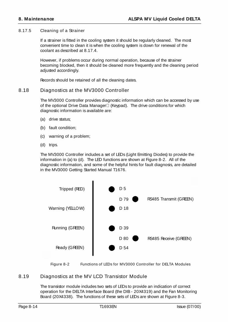
8. Maintenance ALSPA MV Liquid Cooled DELTA
Page 8-14 T1693EN Issue (07/00)
8.17.5 Cleaning of a Strainer
If a strainer is fitted in the cooling system it should be regularly cleaned. The mostconvenient time to clean it is when the cooling system is down for renewal of thecoolant as described at 8.17.4.
However, if problems occur during normal operation, because of the strainerbecoming blocked, then it should be cleaned more frequently and the cleaning periodadjusted accordingly.
Records should be retained of all the cleaning dates.
8.18 Diagnostics at the MV3000 Controller
The MV3000 Controller provides diagnostic information which can be accessed by useof the optional Drive Data Manager (Keypad). The drive conditions for whichdiagnostic information is available are:
(a) drive status;
(b) fault condition;
(c) warning of a problem;
(d) trips.
The MV3000 Controller includes a set of LEDs (Light Emitting Diodes) to provide theinformation in (a) to (d). The LED functions are shown at Figure 8-2. All of thediagnostic information, and some of the helpful hints for fault diagnosis, are detailedin the MV3000 Getting Started Manual T1676.
D 5
D 79
D 18
D 39
D 80
RS485 Transmit (GREEN)
RS485 Receive (GREEN)
D 54
Tripped (RED)
Warning (YELLOW)
Running (GREEN)
Ready (GREEN)
Figure 8-2 Functions of LEDs for MV3000 Controller for DELTA Modules
8.19 Diagnostics at the MV LCD Transistor Module
The transistor module includes two sets of LEDs to provide an indication of correctoperation for the DELTA Interface Board (the DIB - 20X4319) and the Fan MonitoringBoard (20X4338). The functions of these sets of LEDs are shown at Figure 8-3.
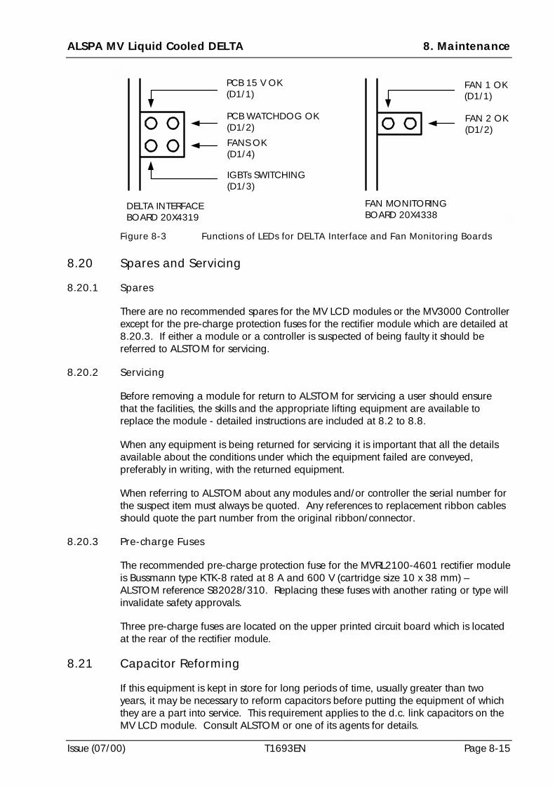
ALSPA MV Liquid Cooled DELTA 8. Maintenance
Issue (07/00) T1693EN Page 8-15
DELTA INTERFACEBOARD 20X4319
PCB 15 V OK(D1/1)
PCB WATCHDOG OK(D1/2)
FANS OK(D1/4)
IGBTs SWITCHING(D1/3)
FAN MONITORINGBOARD 20X4338
FAN 1 OK(D1/1)
FAN 2 OK(D1/2)
Figure 8-3 Functions of LEDs for DELTA Interface and Fan Monitoring Boards
8.20 Spares and Servicing
8.20.1 Spares
There are no recommended spares for the MV LCD modules or the MV3000 Controllerexcept for the pre-charge protection fuses for the rectifier module which are detailed at8.20.3. If either a module or a controller is suspected of being faulty it should bereferred to ALSTOM for servicing.
8.20.2 Servicing
Before removing a module for return to ALSTOM for servicing a user should ensurethat the facilities, the skills and the appropriate lifting equipment are available toreplace the module - detailed instructions are included at 8.2 to 8.8.
When any equipment is being returned for servicing it is important that all the detailsavailable about the conditions under which the equipment failed are conveyed,preferably in writing, with the returned equipment.
When referring to ALSTOM about any modules and/or controller the serial number forthe suspect item must always be quoted. Any references to replacement ribbon cablesshould quote the part number from the original ribbon/connector.
8.20.3 Pre-charge Fuses
The recommended pre-charge protection fuse for the MVRL2100-4601 rectifier moduleis Bussmann type KTK-8 rated at 8 A and 600 V (cartridge size 10 x 38 mm) –ALSTOM reference S82028/310. Replacing these fuses with another rating or type willinvalidate safety approvals.
Three pre-charge fuses are located on the upper printed circuit board which is locatedat the rear of the rectifier module.
8.21 Capacitor Reforming
If this equipment is kept in store for long periods of time, usually greater than twoyears, it may be necessary to reform capacitors before putting the equipment of whichthey are a part into service. This requirement applies to the d.c. link capacitors on theMV LCD module. Consult ALSTOM or one of its agents for details.
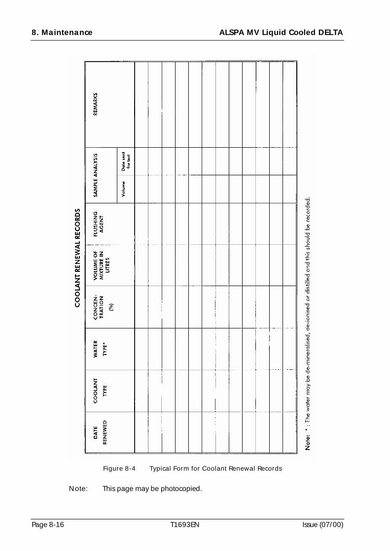
8. Maintenance ALSPA MV Liquid Cooled DELTA
Page 8-16 T1693EN Issue (07/00)
Note: This page may be photocopied.
Figure 8-4 Typical Form for Coolant Renewal Records
ALSPA MV Liquid Cooled DELTA 9. Disposal
Issue (07/00) T1693EN Page 9-1
9. Disposal
This equipment or any part of the equipment should be disposed of in accordance withthe laws of the country of use.
Modern high technology materials have been used in the manufacture of theequipment to ensure optimum performance. Care has been taken with the selection ofthese materials to minimise risks to health and safety. However, some materials requirespecial consideration during disposal.
In common with all products of this type, the high voltage electrolytic capacitors containan electrolyte which must be disposed of as hazardous waste. The electrolytes aresolutions of organic and/or boric acid. The major solvents in the capacitors arebutyrolactone and ethylene glycol. The electrolyte is non-carcinogenic, but may causeirritation to the skin if contact is prolonged.
Liquid coolant is subject to special considerations during handling, storage anddisposal. Refer to the manufacturer’s instructions.
9. Disposal ALSPA MV Liquid Cooled DELTA
Page 9-2 T1693EN Issue (07/00)
(This page intentionally left blank)
ALSPA MV Liquid Cooled DELTA Appendix A - MV LCD Connection Diagrams
Issue (07/00) T1693EN Page A-1
Appendix A MV LCD Connection Diagrams
A.1 Scope
This document shows the standard connections for a.c. input ALSPA MV Liquid CooledDELTA (MV LCD) modular drives (current ratings of 643 A and larger). These modulardrives are constructed using the ALSPA MV LCD modules and range from theconnection of a single Transistor Bridge Module and a Rectifier Bridge Module, tomultiple modules connected in parallel.
This document is based on the installer having the complete parts and circuit elementlists for the drive to be installed. Ensure that ALL parts required are listed before startof installation.
The mechanical and electrical installation of MV LCD modules, the related MV3000controller and User I/O Termination Panel are shown in this manual at Sections 5 and 6.
A.2 Introduction
Each drive circuit diagram is built from a series of circuit elements. This documentcontains a variety of these circuit elements for a range of different drive configurations.(Using circuit elements allows the large number of standard, different driveconfigurations to be shown in one document).
These configurations for MV3000 systems allow different :
(a) main supply inputs, including:
(1) type of supply: 6 pulse or 12 pulse (for harmonic reduction) including:
(i) isolated secondary supply transformer;
(2) supply voltage: 525 - 690 V;
(b) drive current ratings:
(1) 643 A and above;
(2) 1.1 x and 1.5 x overload current ratings for the Transistor Bridge Moduleand, at present time, 1.1 x overload current rating for the Rectifier BridgeModule;
(3) 1 - 6 Machine Transistor Bridge Modules;
(4) 1 - 2 Network Rectifier Bridge Modules.
The complete drive circuit diagram is a set of 6 separate circuit elements. Theseelements are in the form of a letter followed by a number. The letter defines the circuitelement type. The number shows the circuit element configuration, e.g:
‘J1’ shows a ‘Network Bridge (Power), 6 Pulse Supply Input, 1 (single) Rectifier.
Table A-1 details all the circuit element types used with the ALSPA MV LCD range ofmodules and controller. All of the circuits for each element type are included at A.3.
One circuit element out of each of all 6 sections must be used to generate a complete drive. Figure A-1 shows the outline of a complete drive diagram, using MV LCD modules.
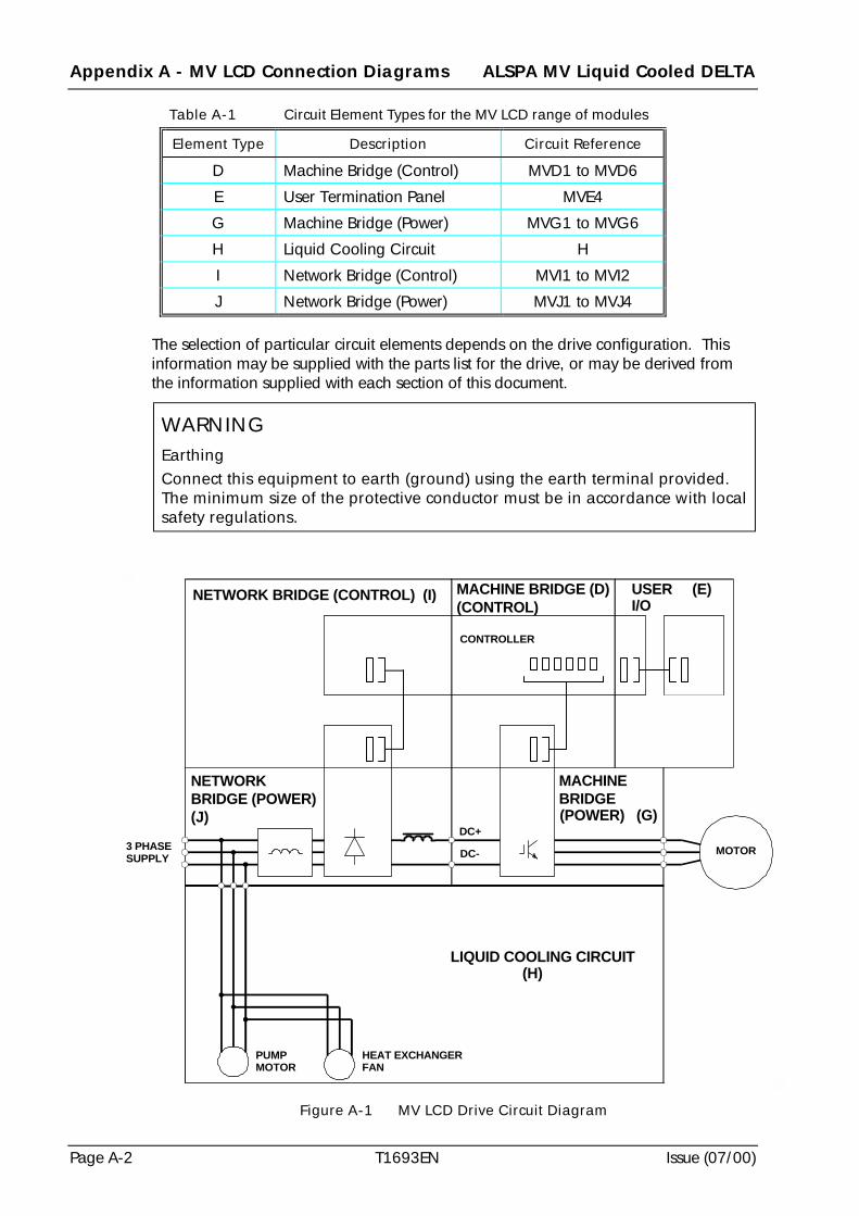
Appendix A - MV LCD Connection Diagrams ALSPA MV Liquid Cooled DELTA
Page A-2 T1693EN Issue (07/00)
Table A-1 Circuit Element Types for the MV LCD range of modules
Element Type Description Circuit Reference
D Machine Bridge (Control) MVD1 to MVD6
E User Termination Panel MVE4
G Machine Bridge (Power) MVG1 to MVG6
H Liquid Cooling Circuit H
I Network Bridge (Control) MVI1 to MVI2
J Network Bridge (Power) MVJ1 to MVJ4
The selection of particular circuit elements depends on the drive configuration. Thisinformation may be supplied with the parts list for the drive, or may be derived fromthe information supplied with each section of this document.
Figure A-1 MV LCD Drive Circuit Diagram
NETWORK BRIDGE (CONTROL) (I) MACHINE BRIDGE (D)(CONTROL)
USER (E)I/O
NETWORKBRIDGE (POWER)(J)
MACHINEBRIDGE(POWER) (G)
MOTOR
LIQUID COOLING CIRCUIT (H)
PUMPMOTOR
HEAT EXCHANGERFAN
3 PHASESUPPLY
DC+
DC-
CONTROLLER
WARNINGEarthingConnect this equipment to earth (ground) using the earth terminal provided.The minimum size of the protective conductor must be in accordance with localsafety regulations.
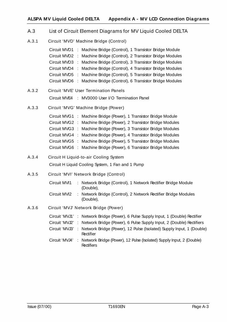
ALSPA MV Liquid Cooled DELTA Appendix A - MV LCD Connection Diagrams
Issue (07/00) T1693EN Page A-3
A.3 List of Circuit Element Diagrams for MV Liquid Cooled DELTA
A.3.1 Circuit ‘MVD’ Machine Bridge (Control)
Circuit MVD1 : Machine Bridge (Control), 1 Transistor Bridge ModuleCircuit MVD2 : Machine Bridge (Control), 2 Transistor Bridge ModulesCircuit MVD3 : Machine Bridge (Control), 3 Transistor Bridge ModulesCircuit MVD4 : Machine Bridge (Control), 4 Transistor Bridge ModulesCircuit MVD5 : Machine Bridge (Control), 5 Transistor Bridge ModulesCircuit MVD6 : Machine Bridge (Control), 6 Transistor Bridge Modules
A.3.2 Circuit ‘MVE’ User Termination Panels
Circuit MVE4 : MV3000 User I/O Termination Panel
A.3.3 Circuit ‘MVG’ Machine Bridge (Power)
Circuit MVG1 : Machine Bridge (Power), 1 Transistor Bridge ModuleCircuit MVG2 : Machine Bridge (Power), 2 Transistor Bridge ModulesCircuit MVG3 : Machine Bridge (Power), 3 Transistor Bridge ModulesCircuit MVG4 : Machine Bridge (Power), 4 Transistor Bridge ModulesCircuit MVG5 : Machine Bridge (Power), 5 Transistor Bridge ModulesCircuit MVG6 : Machine Bridge (Power), 6 Transistor Bridge Modules
A.3.4 Circuit H Liquid-to-air Cooling System
Circuit H Liquid Cooling System, 1 Fan and 1 Pump
A.3.5 Circuit ‘MVI’ Network Bridge (Control)
Circuit MVI1 : Network Bridge (Control), 1 Network Rectifier Bridge Module(Double),
Circuit MVI2 : Network Bridge (Control), 2 Network Rectifier Bridge Modules(Double),
A.3.6 Circuit ‘MVJ’ Network Bridge (Power)
Circuit ‘MVJ1’ : Network Bridge (Power), 6 Pulse Supply Input, 1 (Double) RectifierCircuit ‘MVJ2’ : Network Bridge (Power), 6 Pulse Supply Input, 2 (Double) RectifiersCircuit ‘MVJ3’ : Network Bridge (Power), 12 Pulse (Isolated) Supply Input, 1 (Double)
RectifierCircuit ‘MVJ4’ : Network Bridge (Power), 12 Pulse (Isolated) Supply Input, 2 (Double)
Rectifiers
Appendix A - MV LCD Connection Diagrams ALSPA MV Liquid Cooled DELTA
Page A-4 T1693EN Issue (07/00)
A.4 Machine Bridge (Control)
This section is based on:
(a) use of MV3000 Controller with one Power Interface Board (PIB);
(b) number of Transistor Bridge Modules - dependent on drive current rating.
A.4.1 Circuit ‘MVD1’ Machine Bridge (Control), 1 Transistor Bridge Module
NetworkBridgeRectifier
User I/OTermination
Panel
Keypad
MV3000CONTROLLER
PL2
PL7
PL3
PL4
PL5
PL6
PL20
PL12
SK5
BRIDGE 1
TRANSISTORBRIDGE
MODULE
PL3
PL1
A
C
B
+
-
TB1SMPS
DELTAINTERFACE
BOARD
DIB
ALSPA MV Liquid Cooled DELTA Appendix A - MV LCD Connection Diagrams
Issue (07/00) T1693EN Page A-5
A.4.2 Circuit ‘MVD2’ Machine Bridge (Control), 2 Transistor Bridge Modules
NetworkBridgeRectifier
User I/OTermination
Panel
Keypad
MV3000CONTROLLER
PL2
PL7
PL3
PL4
PL5
PL6
PL20
PL12
SK5
TRANSISTORBRIDGE
MODULE
PL3
PL1
A
C
B
+
-
TB1SMPS
BRIDGE 2
BRIDGE 1
TRANSISTORBRIDGE
MODULE
PL3
PL1
A
C
B
+
-
TB1SMPS
DELTAINTERFACE
BOARD
DIB
DELTAINTERFACE
BOARD
DIB
Appendix A - MV LCD Connection Diagrams ALSPA MV Liquid Cooled DELTA
Page A-6 T1693EN Issue (07/00)
A.4.3 Circuit ‘MVD3’ Machine Bridge (Control), 3 Transistor Bridge Modules
NetworkBridgeRectifier
User I/OTermination
Panel
Keypad
MV3000CONTROLLER
PL2
PL7
PL3
PL4
PL5
PL6
PL20
PL12
SK5
TRANSISTORBRIDGE
MODULE
PL3
PL1
A
C
B
+
-
TB1SMPS
BRIDGE 2
TRANSISTORBRIDGE
MODULE
PL3
PL1
A
C
B
+
-
TB1SMPS
BRIDGE 3
BRIDGE 1
TRANSISTORBRIDGE
MODULE
PL3
PL1
A
C
B
+
-
TB1SMPS
DELTAINTERFACE
BOARD
DIB
DELTAINTERFACE
BOARD
DIB
DELTAINTERFACE
BOARD
DIB
ALSPA MV Liquid Cooled DELTA Appendix A - MV LCD Connection Diagrams
Issue (07/00) T1693EN Page A-7
A.4.4 Circuit ‘MVD4’ Machine Bridge (Control), 4 Transistor Bridge Modules
NetworkBridgeRectifier
User I/OTermination
Panel
Keypad
MV3000CONTROLLER
PL2
PL7
PL3
PL4
PL5
PL6
PL20
PL12
SK5
TRANSISTORBRIDGE
MODULE
PL3
PL1
A
C
B
+
-
TB1SMPS
BRIDGE 2
BRIDGE 1
TRANSISTORBRIDGE
MODULE
PL3
PL1
A
C
B
+
-
TB1SMPS
TRANSISTORBRIDGE
MODULE
PL3
PL1
A
C
B
+
-
TB1SMPS
BRIDGE 4
BRIDGE 3
TRANSISTORBRIDGE
MODULE
PL3
PL1
A
C
B
+
-
TB1SMPS
DELTAINTERFACE
BOARD
DIB
DELTAINTERFACE
BOARD
DIB
DELTAINTERFACE
BOARD
DIB
DELTAINTERFACE
BOARD
DIB
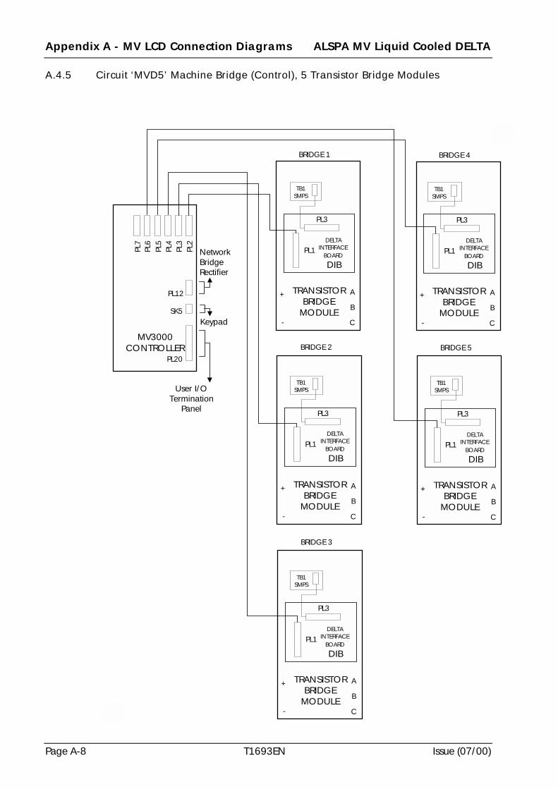
Appendix A - MV LCD Connection Diagrams ALSPA MV Liquid Cooled DELTA
Page A-8 T1693EN Issue (07/00)
A.4.5 Circuit ‘MVD5’ Machine Bridge (Control), 5 Transistor Bridge Modules
NetworkBridgeRectifier
User I/OTermination
Panel
Keypad
MV3000CONTROLLER
PL2
PL7
PL3
PL4
PL5
PL6
PL20
PL12
SK5
TRANSISTORBRIDGE
MODULE
PL3
PL1
A
C
B
+
-
TB1SMPS
BRIDGE 2
TRANSISTORBRIDGE
MODULE
PL3
PL1
A
C
B
+
-
TB1SMPS
BRIDGE 3
BRIDGE 1
TRANSISTORBRIDGE
MODULE
PL3
PL1
A
C
B
+
-
TB1SMPS
TRANSISTORBRIDGE
MODULE
PL3
PL1
A
C
B
+
-
TB1SMPS
BRIDGE 5
BRIDGE 4
TRANSISTORBRIDGE
MODULE
PL3
PL1
A
C
B
+
-
TB1SMPS
DELTAINTERFACE
BOARD
DIB
DELTAINTERFACE
BOARD
DIB
DELTAINTERFACE
BOARD
DIB
DELTAINTERFACE
BOARD
DIB
DELTAINTERFACE
BOARD
DIB
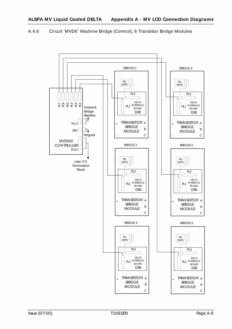
ALSPA MV Liquid Cooled DELTA Appendix A - MV LCD Connection Diagrams
Issue (07/00) T1693EN Page A-9
A.4.6 Circuit ‘MVD6’ Machine Bridge (Control), 6 Transistor Bridge Modules
NetworkBridgeRectifier
User I/OTermination
Panel
Keypad
MV3000CONTROLLER
PL2
PL7
PL3
PL4
PL5
PL6
PL20
PL12
SK5
TRANSISTORBRIDGE
MODULE
PL3
PL1
A
C
B
+
-
TB1SMPS
BRIDGE 2
TRANSISTORBRIDGE
MODULE
PL3
PL1
A
C
B
+
-
TB1SMPS
BRIDGE 3
BRIDGE 1
TRANSISTORBRIDGE
MODULE
PL3
PL1
A
C
B
+
-
TB1SMPS
TRANSISTORBRIDGE
MODULE
PL3
PL1
A
C
B
+
-
TB1SMPS
BRIDGE 5
TRANSISTORBRIDGE
MODULE
PL3
PL1
A
C
B
+
-
TB1SMPS
BRIDGE 6
BRIDGE 4
TRANSISTORBRIDGE
MODULE
PL3
PL1
A
C
B
+
-
TB1SMPS
DELTAINTERFACE
BOARD
DIB
DELTAINTERFACE
BOARD
DIB
DELTAINTERFACE
BOARD
DIB
DELTAINTERFACE
BOARD
DIB
DELTAINTERFACE
BOARD
DIB
DELTAINTERFACE
BOARD
DIB
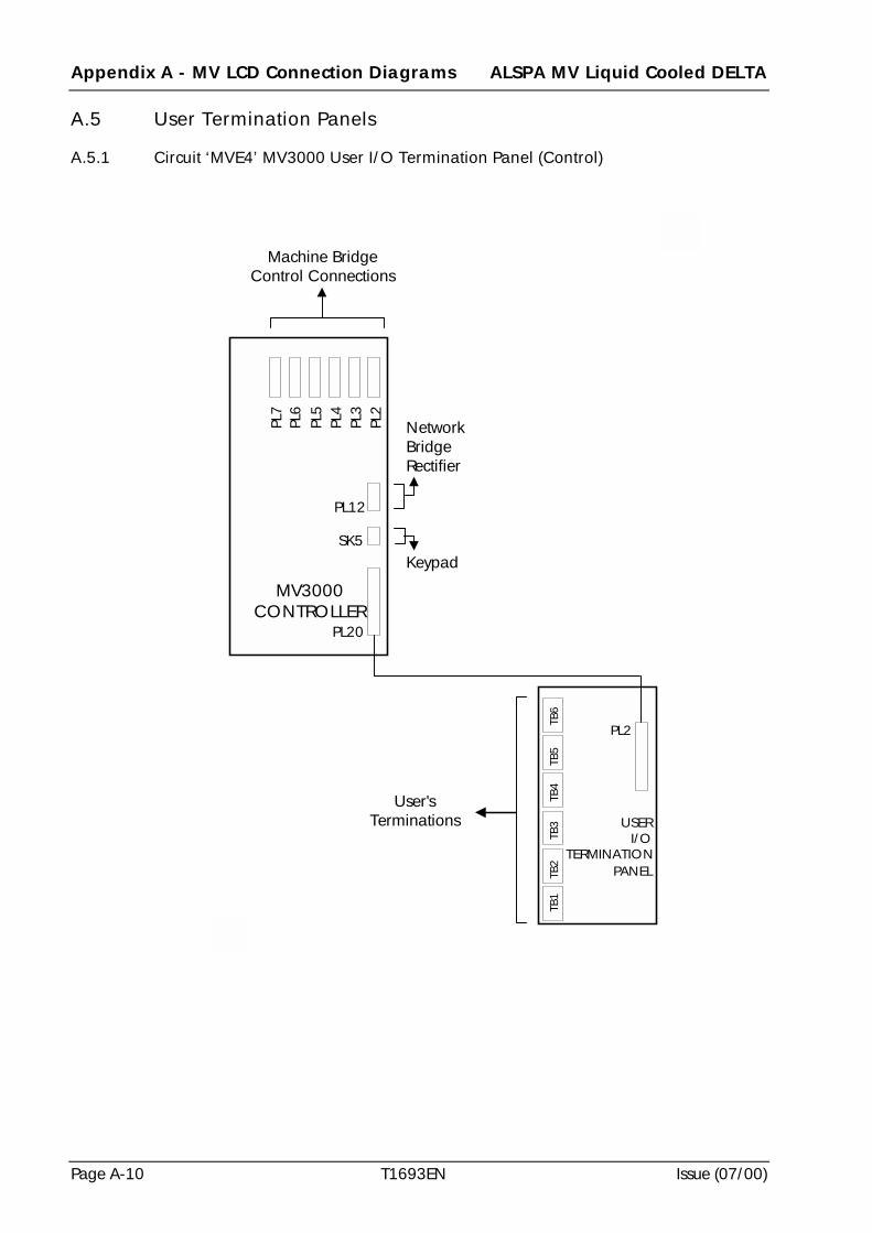
Appendix A - MV LCD Connection Diagrams ALSPA MV Liquid Cooled DELTA
Page A-10 T1693EN Issue (07/00)
A.5 User Termination Panels
A.5.1 Circuit ‘MVE4’ MV3000 User I/O Termination Panel (Control)
NetworkBridgeRectifier
Keypad
MV3000CONTROLLER
PL2
PL7
PL3
PL4
PL5
PL6
PL20
PL12
SK5
USERI/O
TERMINATIONPANEL
PL2
TB1
TB2
TB3
TB4
TB5
TB6
User'sTerminations
Machine BridgeControl Connections
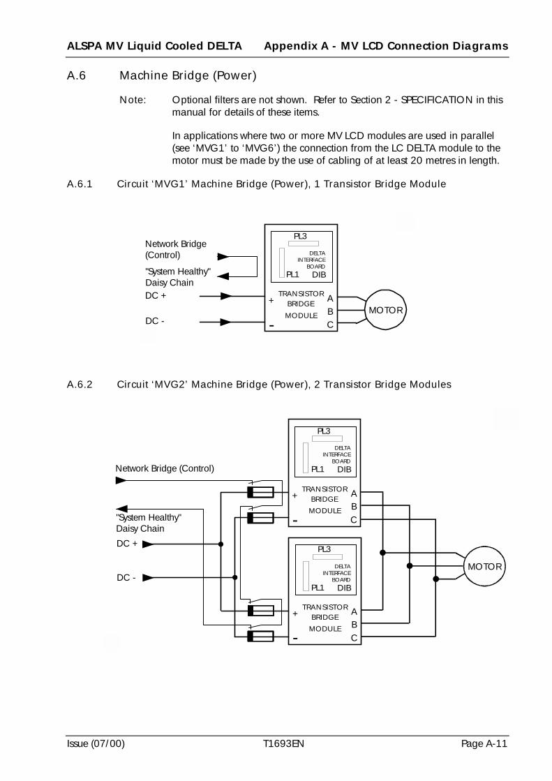
ALSPA MV Liquid Cooled DELTA Appendix A - MV LCD Connection Diagrams
Issue (07/00) T1693EN Page A-11
A.6 Machine Bridge (Power)
Note: Optional filters are not shown. Refer to Section 2 - SPECIFICATION in thismanual for details of these items.
In applications where two or more MV LCD modules are used in parallel(see ‘MVG1’ to ‘MVG6’) the connection from the LC DELTA module to themotor must be made by the use of cabling of at least 20 metres in length.
A.6.1 Circuit ‘MVG1’ Machine Bridge (Power), 1 Transistor Bridge Module
A.6.2 Circuit ‘MVG2’ Machine Bridge (Power), 2 Transistor Bridge Modules
TRANSISTORBRIDGE
MODULE
PL3
A
CB
+
-
DC +
DC -MOTOR
Network Bridge(Control)
"System Healthy"Daisy Chain
PL1
DELTAINTERFACE
BOARD
DIB
TRANSISTORBRIDGE
MODULE
PL3
A
CB
+
-
TRANSISTORBRIDGE
MODULE
PL3
A
CB
+
-
DC +
DC -MOTOR
Network Bridge (Control)
"System Healthy"Daisy Chain
PL1
DELTAINTERFACE
BOARD
DIB
PL1
DELTAINTERFACE
BOARD
DIB
Appendix A - MV LCD Connection Diagrams ALSPA MV Liquid Cooled DELTA
Page A-12 T1693EN Issue (07/00)
A.6.3 Circuit ‘MVG3’ Machine Bridge (Power), 3 Transistor Bridge Modules
TRANSISTORBRIDGE
MODULE
PL3
A
CB
+
-
TRANSISTORBRIDGE
MODULE
PL3
A
CB
+
-
TRANSISTORBRIDGE
MODULE
PL3
A
CB
+
-
DC +
DC -
MOTOR
Network Bridge (Control)
"System Healthy"Daisy Chain
PL1
DELTAINTERFACE
BOARD
DIB
PL1
DELTAINTERFACE
BOARD
DIB
PL1
DELTAINTERFACE
BOARD
DIB
ALSPA MV Liquid Cooled DELTA Appendix A - MV LCD Connection Diagrams
Issue (07/00) T1693EN Page A-13
A.6.4 Circuit ‘MVG4’ Machine Bridge (Power), 4 Transistor Bridge Modules
DC +
DC -
BRIDGE 3
TRANSISTORBRIDGE
MODULE
PL3
A
CB
+
-
TRANSISTORBRIDGE
MODULE
PL3
A
CB
+
-
BRIDGE 1
TRANSISTORBRIDGE
MODULE
PL3
A
CB
+
-
BRIDGE 2
TRANSISTORBRIDGE
MODULE
PL3
A
CB
+
-
BRIDGE 4
MOTOR
Network Bridge (Control)
"System Healthy"Daisy Chain
PL1
DELTAINTERFACE
BOARD
DIB
PL1
DELTAINTERFACE
BOARD
DIB
PL1
DELTAINTERFACE
BOARD
DIB
PL1
DELTAINTERFACE
BOARD
DIB
Appendix A - MV LCD Connection Diagrams ALSPA MV Liquid Cooled DELTA
Page A-14 T1693EN Issue (07/00)
A.6.5 Circuit ‘MVG5’ Machine Bridge (Power), 5 Transistor Bridge Modules
BRIDGE 1
PL3
A
CB
+
-
BRIDGE 2
PL3
A
CB
+
-
BRIDGE 3
PL3
A
CB
+
-
BRIDGE 4
PL3
A
CB
+
-
BRIDGE 5
PL3
A
CB
+
-
DC +
DC -
"System Healthy"Daisy Chain
Machine Bridge (Control)
MOTOR
TRANSISTORBRIDGE
MODULE
TRANSISTORBRIDGE
MODULE
TRANSISTORBRIDGE
MODULE
TRANSISTORBRIDGE
MODULE
TRANSISTORBRIDGE
MODULE
PL1
DELTAINTERFACE
BOARD
DIB
PL1
DELTAINTERFACE
BOARD
DIB
PL1
DELTAINTERFACE
BOARD
DIB
PL1
DELTAINTERFACE
BOARD
DIB
PL1
DELTAINTERFACE
BOARD
DIB
ALSPA MV Liquid Cooled DELTA Appendix A - MV LCD Connection Diagrams
Issue (07/00) T1693EN Page A-15
A.6.6 Circuit ‘MVG6’ Machine Bridge (Power), 6 Transistor Bridge Modules
BRIDGE 1
PL3
A
CB
+
-
BRIDGE 2
PL3
A
CB
+
-
BRIDGE 3
PL3
A
CB
+
-
BRIDGE 4
PL3
A
CB
+
-
BRIDGE 5
PL3
A
CB
+
-
PL3
A
CB
+
-
DC +
DC -
BRIDGE 6
TRANSISTORBRIDGE
MODULE
TRANSISTORBRIDGE
MODULE
TRANSISTORBRIDGE
MODULE
TRANSISTORBRIDGE
MODULE
TRANSISTORBRIDGE
MODULE
TRANSISTORBRIDGE
MODULE
MOTOR
"System Healthy"Daisy Chain
Machine Bridge (Control) PL1
DELTAINTERFACE
BOARD
DIB
PL1
DELTAINTERFACE
BOARD
DIB
PL1
DELTAINTERFACE
BOARD
DIB
PL1
DELTAINTERFACE
BOARD
DIB
PL1
DELTAINTERFACE
BOARD
DIB
PL1
DELTAINTERFACE
BOARD
DIB
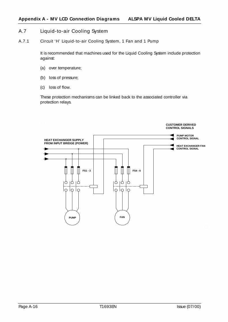
Appendix A - MV LCD Connection Diagrams ALSPA MV Liquid Cooled DELTA
Page A-16 T1693EN Issue (07/00)
A.7 Liquid-to-air Cooling System
A.7.1 Circuit ‘H’ Liquid-to-air Cooling System, 1 Fan and 1 Pump
It is recommended that machines used for the Liquid Cooling System include protectionagainst:
(a) over temperature;
(b) loss of pressure;
(c) loss of flow.
These protection mechanisms can be linked back to the associated controller viaprotection relays.
HEAT EXCHANGER SUPPLYFROM INPUT BRIDGE (POWER)
FS1 - 3 FS4 - 6
CUSTOMER DERIVEDCONTROL SIGNALS
PUMP MOTORCONTROL SIGNAL
HEAT EXCHANGER FANCONTROL SIGNAL
PUMP FAN
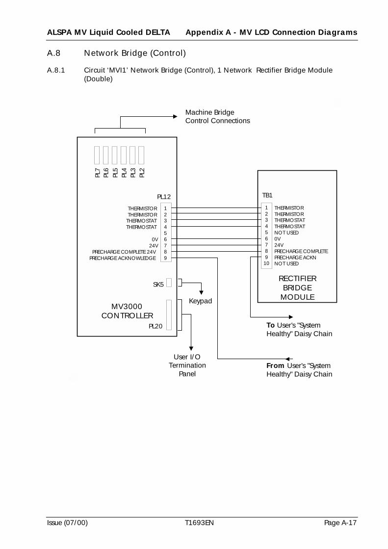
ALSPA MV Liquid Cooled DELTA Appendix A - MV LCD Connection Diagrams
Issue (07/00) T1693EN Page A-17
A.8 Network Bridge (Control)
A.8.1 Circuit ‘MVI1’ Network Bridge (Control), 1 Network Rectifier Bridge Module(Double)
MV3000CONTROLLER
PL20
Machine BridgeControl Connections
PL2
PL7
PL3
PL4
PL5
PL6
SK5
123456789
THERMISTORTHERMISTOR
THERMOSTATTHERMOSTAT
0V24V
PRECHARGE COMPLETE 24VPRECHARGE ACKNOWLEDGE
From User's "SystemHealthy" Daisy Chain
Keypad
User I/OTermination
Panel
PL12
To User's "SystemHealthy" Daisy Chain
RECTIFIERBRIDGE
MODULE
123456789
10
THERMISTORTHERMISTORTHERMOSTATTHERMOSTATNOT USED0V24VPRECHARGE COMPLETEPRECHARGE ACKNNOT USED
TB1
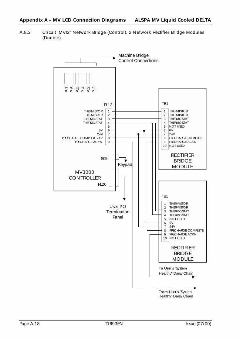
Appendix A - MV LCD Connection Diagrams ALSPA MV Liquid Cooled DELTA
Page A-18 T1693EN Issue (07/00)
A.8.2 Circuit ‘MVI2’ Network Bridge (Control), 2 Network Rectifier Bridge Modules(Double)
MV3000CONTROLLER
PL20
Machine BridgeControl Connections
PL2
PL7
PL3
PL4
PL5
PL6
SK5
123456789
THERMISTORTHERMISTOR
THERMOSTATTHERMOSTAT
0V24V
PRECHARGE COMPLETE 24VPRECHARGE ACK'N
From User's "SystemHealthy" Daisy Chain
Keypad
User I/OTermination
Panel
PL12
To User's "SystemHealthy" Daisy Chain
RECTIFIERBRIDGE
MODULE
12345678910
THERMISTORTHERMISTORTHERMOSTATTHERMOSTATNOT USED0V24VPRECHARGE COMPLETEPRECHARGE ACK'NNOT USED
RECTIFIERBRIDGE
MODULE
123456789
10
THERMISTORTHERMISTORTHERMOSTATTHERMOSTATNOT USED0V24VPRECHARGE COMPLETEPRECHARGE ACK'NNOT USED
TB1
TB1
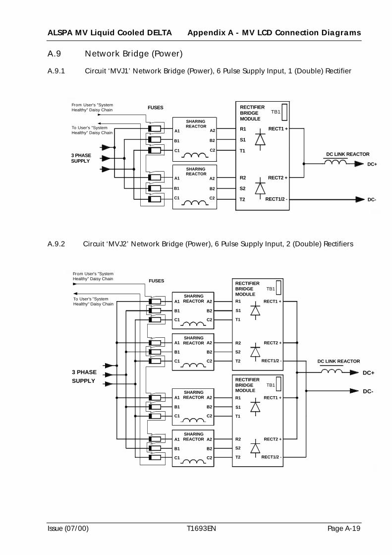
ALSPA MV Liquid Cooled DELTA Appendix A - MV LCD Connection Diagrams
Issue (07/00) T1693EN Page A-19
A.9 Network Bridge (Power)
A.9.1 Circuit ‘MVJ1’ Network Bridge (Power), 6 Pulse Supply Input, 1 (Double) Rectifier
A.9.2 Circuit ‘MVJ2’ Network Bridge (Power), 6 Pulse Supply Input, 2 (Double) Rectifiers
3 PHASESUPPLY
DC-
DC LINK REACTOR
FUSES
RECT1/2 -
RECT2 +
RECTIFIERBRIDGEMODULE
RECT1 +
TB1
DC+
SHARINGREACTOR
SHARINGREACTOR
B1
C1
A1
B1
C1
A1
B2
C2
A2
B2
C2
A2
S1
T1
R1
T2
S2
R2
From User's "SystemHealthy" Daisy Chain
To User's "SystemHealthy" Daisy Chain
3 PHASESUPPLY
FUSES
RECT1/2 -
RECT2 +
RECT1 +
TB1DC-
RECT1/2 -
RECT2 +
RECT1 +
TB1RECTIFIERBRIDGEMODULE
DC LINK REACTOR
SHARINGREACTOR
C1
B1
A1
C2
B2
A2
C2
B2
A2SHARINGREACTOR
C1
B1
A1
C2
B2
A2SHARINGREACTOR
C1
B1
A1
SHARINGREACTOR
C1
B1
A1
C2
B2
A2
RECTIFIERBRIDGEMODULE
T1
R1
S1
T1
R1
S1
T2
S2
R2
T2
S2
R2
From User's "SystemHealthy" Daisy Chain
To User's "SystemHealthy" Daisy Chain
DC+
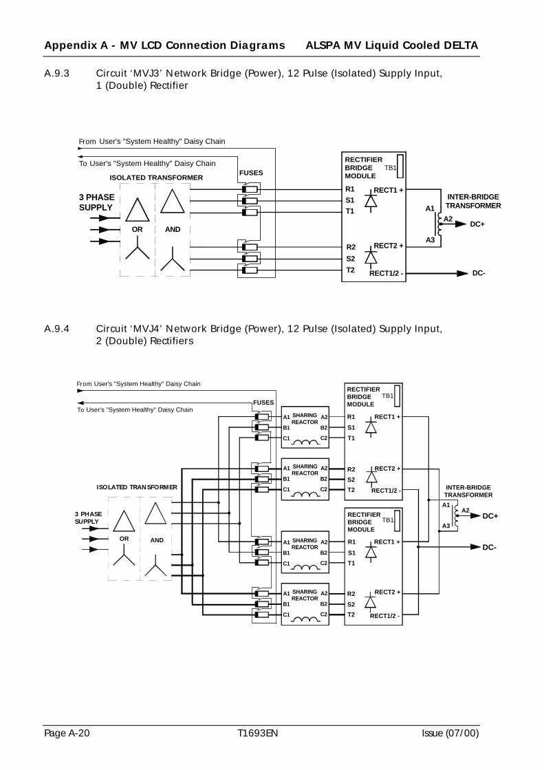
Appendix A - MV LCD Connection Diagrams ALSPA MV Liquid Cooled DELTA
Page A-20 T1693EN Issue (07/00)
A.9.3 Circuit ‘MVJ3’ Network Bridge (Power), 12 Pulse (Isolated) Supply Input,1 (Double) Rectifier
A.9.4 Circuit ‘MVJ4’ Network Bridge (Power), 12 Pulse (Isolated) Supply Input,2 (Double) Rectifiers
INTER-BRIDGETRANSFORMER
ISOLATED TRANSFORMER
ANDOR
3 PHASESUPPLY
FUSESTB1
RECT1/2 -
RECT2 +
RECT1 +
T2S2R2
S1T1
R1
A3
A1
DC+A2
RECTIFIERBRIDGEMODULE
From User's "System Healthy" Daisy Chain
To User's "System Healthy" Daisy Chain
DC-
T2 RECT1/2 -
S2R2 RECT2 +
R1 RECT1 +
T1S1
TB1
DC-
DC+
T1
R2 RECT2 +
T2S2
RECT1/2 -
SHARINGREACTOR
TB1
R1S1
RECT1 +
RECTIFIERBRIDGEMODULE
INTER-BRIDGETRANSFORMER
3 PHASESUPPLY
B1
C1
A1
B1
C1
A1
B1
C1
A1
B1
C1
A1
SHARINGREACTOR
SHARINGREACTOR
SHARINGREACTOR
C2
A2
B2
C2
A2
B2
C2
A2
B2
C2
A2
B2
RECTIFIERBRIDGEMODULE
From User's "System Healthy" Daisy Chain
To User's "System Healthy" Daisy Chain
A1A2
A3
OR AND
ISOLATED TRANSFORMER
FUSES
ALSPA MV Liquid Cooled DELTA Appendix B - Recommended Torque Settings
Issue (07/00) T1693EN Page B-1
Appendix B Recommended Torque Settings
B.1 Scope
This document details the recommended tightening torque settings for connectors usedon the ALSPA MV LCD based modules.
The recommended torque settings are applicable to high-tensile steel (Grade 8.8)fasteners fitted with a single turn spring washer under the nut, and with the threadsbeing zinc plated, passivated and unlubricated over the normal operating temperatureof these components.
Specifically excluded are :
(a) fasteners with any other material (e.g. brass);
(b) fasteners with any other finish (e.g. raw steel, cadmium plated, lubrication of anysort);
(c) slotted holes in either steel or copper.
B.2 Torque Settings for Electrical Connections
The figures included at Table B-1 are for electrical connections of copper conductorcrimps to device terminals and to all copperwork except busbars for which figures areincluded at Table B-2.
B.3 Torque Settings for Busbar Joints
The figures at Table B-2 are for all busbar joints on copperwork.
B.4 Torque Settings for Mechanical Connections
The figures at Table B-3 are for the assembly and mounting of steel parts wherespecific electrical connection, other than continuity, is not involved.
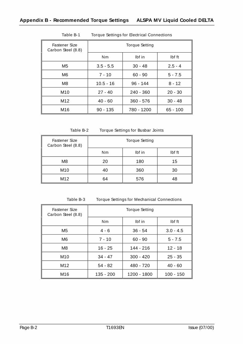
Appendix B - Recommended Torque Settings ALSPA MV Liquid Cooled DELTA
Page B-2 T1693EN Issue (07/00)
Table B-1 Torque Settings for Electrical Connections
Fastener SizeCarbon Steel (8.8)
Torque Setting
Nm lbf in lbf ft
M5 3.5 - 5.5 30 - 48 2.5 - 4
M6 7 - 10 60 - 90 5 - 7.5
M8 10.5 - 16 96 - 144 8 - 12
M10 27 - 40 240 - 360 20 - 30
M12 40 - 60 360 - 576 30 - 48
M16 90 - 135 780 - 1200 65 - 100
Table B-2 Torque Settings for Busbar Joints
Fastener SizeCarbon Steel (8.8)
Torque Setting
Nm lbf in lbf ft
M8 20 180 15
M10 40 360 30
M12 64 576 48
Table B-3 Torque Settings for Mechanical Connections
Fastener SizeCarbon Steel (8.8)
Torque Setting
Nm lbf in lbf ft
M5 4 - 6 36 - 54 3.0 - 4.5
M6 7 - 10 60 - 90 5 - 7.5
M8 16 - 25 144 - 216 12 - 18
M10 34 - 47 300 - 420 25 - 35
M12 54 - 82 480 - 720 40 - 60
M16 135 - 200 1200 - 1800 100 - 150
ALSPA MV Liquid Cooled DELTA Index
Issue (07/00) T1693EN Page Ix-i
Index
Introduction
This index applies to the English Edition of the T1693 Technical Manual for the ALSPA MV LiquidCooled DELTA Drive System.
The index is prepared with word-by-word alphabetisation and is presented with page numbers forsubject location. Page numbers for appendices are prefixed with the appendix letter e.g. A-1 in theindex is Appendix A page 1.
1
12 pulse input rectifier ....................................................2-11
5
50Y6945/01 ......................................................................4-350Y7585/01 ......................................................................4-350Y7589/01 ......................................................................4-350Y7593/01 ......................................................................4-350Y9720/01 ......................................................................4-350Y9724/01 ......................................................................4-350Y9728/01 ......................................................................4-350Y9732/01 ......................................................................4-350Z0119/02............................... 1-14, 2-11, 2-12, 4-10, 5-19
A
a.c. supply fusing................................ see fuse(s) - a.c.supplyacoustic noise .......................................................... 2-7, 2-10air inlet ..............................................................................4-7altitude
operating ......................................................................2-3storage ..........................................................................2-3transport .......................................................................2-3
anti-condensation heaters ..................................................2-3antifreeze.............................................................. see coolantarmoured cable .....................................................see cable(s)
B
ball valves ........................................................ 1-17, 3-6, 7-7bleed
cooling system .............................................................7-7screw material ..............................................................7-7
brass ................................................................................2-13bridge
12 pulse ........................................................................1-2machine ................................................................ 1-6, 6-7
see also connection diagramsnetwork .............................................................. 1-9, 1-10
see also connection diagramsbusbar(s)..........................................2-7, 2-10, 5-14, 6-1, B-1
C
cable connection(s)access on rectifier ........................................................4-3modules to MV3000 controller ................... 6-1, 6-6, 6-10
cable(s)armoured ......................................................................4-5connections - user i/o .................................................6-11control connections - controller............................ 2-4, 6-9control connections - rectifier............................... 2-7, 6-3control connections - transistor .......................... 2-10, 6-6disconnection ...............................................................8-3lengths
current sharing.......................................................2-11minimum .............................................. 1-14, 2-11, 6-7
powerhigh temperature............................................ 2-7, 2-10motor star connected .............................................2-11sizes.......................................................................2-10
power connections................................................ 6-3, 6-7ribbon length ................................................................6-7routing........................................................... 4-4, 4-5, 6-6segregation ........................................................... 4-5, 4-6
capacitor reforming .........................................................8-15caution(s)
avoidance of swarf .....................................................5-15electrostatic discharge ..................................................6-1essential use of stainless steel.......................................8-1flushing module............................................................8-6handling to avoid module damage........................ 5-8, 8-4restraining of conductors..............................................6-1storage of undiluted coolant .......................................8-12termination method to avoid overheating.....................6-1transporting module without coolant............................8-6
circuit breakers ................................................................1-13
Index ALSPA MV Liquid Cooled DELTA
Page Ix-ii T1693EN Issue (07/00)
commissioning........................................................... 7-1, 7-8checks for instrumentation and control........................ 7-8coolant temperature checks.......................................... 7-8filling cooling system
precautions.............................................................. 7-6procedure ............................................................... 7-6
insulation tests ...................................................... 7-3, 7-4pre-commissioning checks........................................... 7-2pre-commissioning electrical checks ........................... 7-2pre-commissioning mechanical checks........................ 7-2preparation of cooling system
initial checks........................................................... 7-6initial tests............................................................... 7-6
running coolant pump only.......................................... 7-7commutation notches........................................................ 4-5compatibility
between ALSTOM GD and MV systems .................. 1-18coolants................................................................. 3-7, 7-6cooling system materials................................... 2-12, 2-13electromagnetic...................................... 2-2, 4-1, 4-4, 6-1
components for example driveoptional...................................................................... 4-10required...................................................................... 4-10user supplied.............................................................. 4-10
condensate ......................................................1-18, 4-10, 5-8condensation.......................................................2-3, 3-5, 5-2conduit.............................................................................. 4-5configurable components.................................................. 7-3configuration
current.......................................................................... 1-2input and output........................................................... 1-7modules ................................................................1-2, 4-1software ................................................................1-2, 6-9system...................................................................1-1, 1-2voltage ......................................................................... 1-2
connection diagramsdrive circuit diagram................................................... A-2liquid-to-air cooling system.............................. A-3, A-16machine bridge (control) .................................... A-3, A-4machine bridge (power).................................... A-3, A-11network bridge (control) ................................... A-3, A-17network bridge (power) .......................... A-3, A-19, A-20user termination panel ...................................... A-3, A-10
connection(s)controller ................................................................... 6-10Drive Data ManagerTM . ............................................ 6-11interbridge transformer .............. see connection diagrams
- network bridge (power)rectifier ........................................................................ 6-2
a.c. ...................................................................2-7, 6-3control..............................................................2-7, 6-3d.c. .......................................................................... 6-3earth/ground............................................................ 6-3liquid..............................................................5-20, 8-5sizes/type ................................................................ 2-7
SMPS......................................................................... 6-14
transistora.c. ...................................................................2-9, 6-7control..................................................................... 6-6d.c. .......................................................................... 6-7earth/ground............................................................ 6-7liquid .............................................................. 5-20, 8-5sizes/type ................................................................ 2-9
user i/o termination panel .......................................... 6-11contactors..........................................................4-10, 6-8, 7-4control signals................................................................. 2-10controller .................................................................1-7, 5-14
connections to keypad ........................................6-9, 6-10connections to rectifier module ..........................6-9, 6-10connections to transistor module ........................6-6, 6-10connections to user i/o termination panel ........6-10, 6-11diagnostics ................................................................. 8-14fitting ................................................................5-14, 5-16front access for LEDs .........................................4-3, 6-10mechanical details...................................................... 5-16position ...............................................................4-3, 5-14re-connection ............................................................. 8-10removal ........................................................................ 8-9space around ................................................................ 4-3specification................................................................. 2-1transporting................................................................ 8-10
conversion .................................................................1-1, 4-1convert .............................................................................. 1-9converter ........................................................................... 4-5coolant
concentration ......................................................3-8, 8-13cooling rate .................................................................. 3-9disposal......................................................3-9, 8-11, 8-12flow............................................. 1-16, 3-3, 3-5, 5-21, 7-8flow equalisation ................................................3-5, 5-21flow rate..................................................................... 2-12handling..................................................................... 8-11inhibitors...................................................................... 3-7inlet temperature .................................................2-3, 2-13level ......................................................................3-2, 7-8mixing types ..........................................see coolant - typemixture......................................................................... 3-8outlet temperature .................................................3-2, 3-3pump...................................................... 3-1, 3-4, 7-7, 7-8recommended U.K. Suppliers................see coolant - typerenewal ...............................................................3-9, 8-13renewal records..........................................3-9, 8-13, 8-16separation..................................................................... 3-9storage ....................................................................... 8-12temperature ....................................................3-1, 3-2, 7-8type .............................................................................. 3-7volume in system ......................................................... 3-8volume/weight ........................................................... 2-12water-ethylene glycol.... see coolant type; coolant mixture
coolant connections .......................... see connections - liquidcoolant hose couplings ..................................... see couplings
ALSPA MV Liquid Cooled DELTA Index
Issue (07/00) T1693EN Page Ix-iii
coolingcubicle air.....................................................................2-3
clean, dust-free ........................................................2-3conductive or corrosive gases..................................2-3contamination..........................................................2-3extraction.................................................................2-3obtaining .................................................................2-3
d.c. link capacitors .....................................................1-12cooling duct.................................................... 1-17, 2-13, 3-7cooling fans .............................................................see fan(s)cooling path materials .....................................................2-13cooling rate........................................................................3-9cooling requirements - clean air supply for electronics.....4-7cooling system
controlcoolant pump ‘switch off’ .......................................3-1co-ordination of coolant pump/heat exchanger ......3-1drive start not permitted ..........................................3-1economic use of heat exchanger fan........................3-1interlocking .............................................................3-1
design ...........................................................................3-1external circuit.......................................... 1-17, 3-4, A-16filling
precautions ..............................................................7-6procedure.................................................................7-6
installation of electrical equipment .................. 5-22, 6-16instrumentation
flow rate ..................................................................3-2inlet temperature......................................................3-2level.........................................................................3-2outlet temperature....................................................3-2pressure ...................................................................3-2pump not running....................................................3-2
integration requirements...............................................3-1material compatibility.................................................2-13pipes/couplings – fitting.............................................5-20pipes/couplings – routing ...........................................5-21piping, couplings and fittings – requirement
specification .......................................................3-5preparation
initial checks ...........................................................7-6initial tests ...............................................................7-6
protectionheat exchanger fan not running ...............................3-2heat exchanger in thermal overload.........................3-2level too low............................................................3-2module over temperature.........................................3-2pump not running....................................................3-2temperature too low.................................................3-2
working pressure ........................................................2-13couplings – spring loaded
material.......................................................................2-13on module...................................................................1-17position at module.............................................. 5-20, 8-5requirement specification .............................................3-5
crimp(s) ............................................................ 2-4, 6-1, 6-11
cross membersfor PS4000 cubicle.......................................................5-6
additional lower front ..............................................4-3for Q80 cubicle.............................................................5-3
additional lower front ..............................................4-3cross rails ..................................................see cross memberscubicle
access ...........................................................................4-8ALSTOM Q80 – frame dimensions .............................5-4ALSTOM Q80 – assembling frames for.......................5-3ALSTOM Q80 – fitting supports, cross members........5-5ALSTOM Q80 – installing frame.................................5-2ALSTOM Q80 – layout................................................4-8ALSTOM Q80 – module mounting ................... 1-9, 1-15external ambient temperature .....................................1-16internal ambient temperature......................................1-16Rittal PS4000 – assembling frames for ........................5-6Rittal PS4000 – fitting supports, cross members..........5-7Rittal PS4000 – frame dimensions ..... see ALSTOM Q80Rittal PS4000 – installing frame ..................................5-2Rittal PS4000 – layout .................................................4-8Rittal PS4000 – module mounting ..................... 1-9, 1-15
cubicle depth(s) .................................................. 4-2, 5-3, 5-6cubicle planning ............................................... 4-1, 4-6, 5-14
EMC requirements ........................................ 4-4, 4-5, 4-6enclosure ......................................................................4-8
see also EMC enclosure requirementsgeneral guidance...........................................................4-6installation sequence ....................................................4-9module mounting frame sizes.......................................4-9MV SMPS....................................................................4-4MV3000 Controller......................................................4-3product selection guidance...........................................4-1
cubicle width(s)...........................................4-2, 4-3, 5-3, 5-6current limiting resistor(s) ...............................................1-10current rating(s).................................................................2-4current sharing.................................................................2-11customer support ........................................ see maintenance
D
d.c. feedback terminal TB1 ...............................................6-5d.c. link
capacitors .....................................................................2-9fuses .................................. see fuse(s) - transistor moduleinductor ......................................................................1-14overvoltage trip level....................................................2-9voltage..........................................................................2-9
diagnostics .....................................see controller diagnosticstransistor module diagnostics
dimensionscontroller ....................................................................5-16Drive Data ManagerTM . .............................................5-15interbridge transformer...............................................5-19rectifier module ..........................................................5-11
Index ALSPA MV Liquid Cooled DELTA
Page Ix-iv T1693EN Issue (07/00)
transistor module ....................................................... 5-12user i/o termination panel .......................................... 5-17
DIP switches............................................................6-13, 7-3disposal.............................................. 3-1, 3-9, 8-4, 8-12, 9-1
see also coolant disposaldrip tray ........................................... 1-3, 1-18, 4-9, 4-10, 5-8Drive Data ManagerTM
installation – electrical............................................... 6-11installation – mechanical ........................................... 5-15optional item................................................................ 1-8specification................................................................. 2-4
drive performance data ..................................................... 2-2drive system features ........................................................ 1-2drop – of enclosure in transport - specification ................ 2-3
E
earthterminal – rectifier module ...................................2-7, 6-2terminal – transistor module .................................2-9, 6-5
see also earth/groundearth bonding.............................................................4-5, 8-9earth continuity...................................................4-5, 5-6, 6-8earth/ground
auxiliary input supply ................................................ 6-12bar................................................................................ 7-4checks for motor faults ................................................ 7-3cubicle bonding ...........................................5-6, 6-12, 7-4digital inputs 0V reference ........................................ 6-12symbol ......................................................................... 6-8
earthed/grounded neutral ...........................................2-1, 4-5earthed/grounded parts ..................................................... 7-4earthed-nib Taptite screws................................................ 5-3earthing....................................................... 5-6, 6-8, 7-2, 7-3
see also warning - earthingelectrical data.................................................................... 2-2electrical installation......................................................... 6-1
controller ................................. see controller connectionsDrive Data ManagerTM . ........................................... 6-11fuses........................................................................... 6-14line contactors and relays............................................. 6-8module earthing/grounding.......................................... 6-8
electrical specification ...................................................... 2-1electromagnetic compatibility.................................. see EMCelectrostatic discharge....................................................... 6-1EMC
compliant ..................................................................... 4-4emission of radiation - prevention ............................... 4-5enclosure requirements ................................................ 4-5filter ......................................................................4-4, 4-5filtering ........................................................................ 4-4guidelines..................................................................... 2-2screen filter .................................................................. 4-5
enclosure width(s) .................................. see cubicle width(s)
enclosure(s)general considerations ................................................. 4-2sizes ............................................................................. 4-2steel.............................................................................. 4-2
see also cubicleenergy discharge ....................see warning - energy dischargeenergy storage................................................................. 1-12EPDM
cover .......................................................................... 2-14lining.......................................................................... 2-14
equalisation............................ see coolant - flow equalisationethylene glycol
compatibility..............................................2-13, 2-14, 3-7concentration ...............................................2-12, 3-8, 7-7coolant ....................................................................... 2-12coolant type ................................................................. 3-7disposal........................................................................ 9-1for heat exchanger ....................................................... 3-3freezing point............................................................. 8-12
see also warning – water without corrosion inhibitorscoolant type
ethylene propylene.......................................................... 2-13expansion tank.............................. see header/expansion tank
F
fan(s)assembly pack............................................................ 2-10cubicle ventilation ....................................................... 4-8heat exchanger ventilation ........................................... 3-2monitoring ................................................................. 1-12
fault finding ................................... see controller diagnostics transistor module diagnostics
filterEMC .......................................................... see EMC filterRFI................................................................see RFI filter
filteringelectrical .............................................................1-12, 4-4mechanical ...................................................1-16, 2-3, 5-2
firmware.......................................................................... 6-13flow pipes to manifold ...................................................... 3-6flow rate (of coolant) .............................see coolant flow ratefluid connections ........................... see connection(s) - liquidflushing
agent .......................................................................... 8-13cooling system ........................................................... 8-13
frequencyoperational vibration.................................................... 2-3supply to rectifier bridge module................................. 2-5variable voltage...................................................1-2, 1-11
fuse(s)a.c.supply..................................................................... 2-5contract dependent components................................... 4-7European type gG ........................................................ 2-5for input rectifiers ...................................................... 1-13
ALSPA MV Liquid Cooled DELTA Index
Issue (07/00) T1693EN Page Ix-v
for pre-charge.............................................................8-15for USA and Canada ....................................................2-5indication ...................................................................6-16input line reactors - need for ......................................1-13multiple transistor modules ........................................6-15rectifer/transistor modules..........................................6-14rectifier module ..........................................................6-15selection and mounting ..............................................6-15sequence of assembly ...................................................4-9transistor module............................................... 1-12, 6-16user supplied ..............................................................4-10
G
gasket see Drive Data ManagerTM – installation - mechanicalgland plate.........................................................................4-5ground ..........................................................see earth/groundgrounding ............................................................ see earthing
H
header tankpolyurethane see compatibility - cooling system materials
header/expansion tankheader/expansion tank.......................................................3-4health hazards..................................................see warning(s)health, safety and environmental legislation .........................
.................................................3-9, 8-11, 8-12, 9-1heat dissipation
application variations ...................................................5-2determining cooling rate...............................................3-9for heat exchanger design.............................................3-2rectifier module ............................................................2-6transistor module..........................................................2-9
heat exchangerbypass...........................................................................3-5co-ordination with coolant pump operation .................3-1derating for altitude......................................................3-2economic use of fan......................................................3-1ethylene glycol .....see ethylene glycol for heat exchangerfan not running.............................................................3-2fan operation check ......................................................7-8liquid-to-air ..................................................................3-2liquid-to-liquid .............................................................3-2protection against thermal overload .............................3-2requirement specification .............................................3-2specification .................................................................3-3
heaters ......................................see anti-condensation heatersheatplate
material.......................................................................2-13thermostat protection....................................................2-6
heatsinktemperature see cooling system integration requirements
thermal protection
heavy weights............................ see warning - heavy weightshigh leakage current ........see warning - high leakage currenthigh temperatures ................see warning – high temperatureshose(s)
connection ....................................................................8-8disconnection ................................................ 8-5, 8-6, 8-8for draining...................................................................8-2gloves for handling.......................................................8-2type.............................................................................2-14
I
ingress protection (for enclosure)......................................2-3inhibitors .............................................. see coolant inhibitorsinitialisation.......................................................................1-2installation
of piping and couplings..............................................5-20preparation and planning..............................................4-6sequence.......................................................................4-9
see also electrical installation mechanical installation
instrumentation - cooling system ............. see cooling systeminsulation tests........................................................... 7-3, 7-4integrated intelligent power pack ....................................1-12interbridge transformer
12 pulse input rectifier .............................. 1-6, 1-10, 1-14connections ............................. see connection diagrams –
network bridge (power)mounting ............................................................ 4-8, 5-19rating, terminations, losses .........................................2-11use - standard drive configurations ..............................2-4
interconnectionscontroller to system components ..................................1-4
see also connection diagramsinterlocking circuits...........................................................7-3inversion............................................................................1-1inverter ...................................................................... 4-1, 4-2inverts................................................................................1-2IP…......................................................see ingress protectionisolated neutral ..................................................................2-1isolator ..............................................................................7-3
K
keypad ..........................................see Drive Data ManagerTM
L
LED(s)access to .......................................................................4-4D1/1 to D1/2 ..............................................................8-15D1/1 to D1/4 ...................................................... 6-5, 8-15
see also controller diagnostics transistor module diagnostics
Index ALSPA MV Liquid Cooled DELTA
Page Ix-vi T1693EN Issue (07/00)
lifting a module........................................................5-8, 5-13lifting hole ......................................... 5-8, 5-9, 5-10, 6-2, 6-5lifting points ................................................... see lifting holelifting shackle ................................................................... 5-8liquid connections............................. see connections - liquidliquid cooling system................................see cooling systemload sharing .............................................................1-14, 4-1lower cross member .............................................. see cubiclelower front cross member ..................................... see cubiclelower guide plate(s) ........................... 1-6, 1-15, 4-8, 4-9, 5-8lower rear cross member....................................... see cubicle
M
machine bridge(s) .............................................1-2, 1-6, 2-11magnetic fields.................................................................. 4-5maintenance...................................................................... 8-1
preventive .................................................................. 8-12tools, equipment, materials .......................................... 8-1
manifoldconnections.................................................................. 3-6cubicle mounted................................... 4-3, 4-7, 4-8, 5-20inlet.....................................................................1-17, 3-5material ...................................................................... 2-14outlet...................................................................1-17, 3-5
mechanical installation ..................................................... 5-1mechanical interface(s) for installation of drive ............... 4-7Menu 7 firmware ............................................................ 6-13mixing liquid coolants
see warning – mixing liquid coolantscoolant type
modulecooling system ...........................................1-16, 2-1, 2-12disconnection of wiring ............................................... 8-4earthing..................................................see earth terminalelectrical installation.................................................... 6-1maintenance.............................................see maintenancemechanical installation .........................................5-8, 8-8mounting arrangement ..........................................1-1, 5-3mounting frame – MVDLQ80 type ........................... 2-15mounting frame – MVDLRIT type........................... 2-15mounting frame assembly – for PS4000 ...................... 5-6mounting frame assembly – for Q80............................ 5-3mounting frame checks prior to assembly.................... 4-9mounting frame incompatibility ................................ 1-18mounting frame location.............................................. 4-7mounting frame sizes .... see mounting frame specificationmounting frame specification .................................... 2-14mounting system........................................................ 1-14packing for shipping .................................................... 8-7position ........................................................................ 4-7preparation for shipping .............................................. 8-6re-connection of wiring ............................................... 8-9removal ........................................................................ 8-4repair............................................................................ 8-1
replacement.................................................................. 8-1securing beyond STOP SCREW................................ 5-14shrouds ........................................................... see shroudstransporting.................................................................. 8-6
mounting frame...........................see module mounting framemounting kit ...............................see module mounting framemultiple circuits ......................see warning - multiple circuitsMV3000 ........................................................... see controllerMVC3001-4001 – MV3000 Controller............1-3, 1-4, 4-10MVC3002-4001 – User I/O Termination Panel1-3, 1-4, 4-10MVC3003-4003 – MV SMPS................ 1-3, 1-4, 2-11, 4-10MVC3004-4001 – Ribbon Cable Kit – 1 module............. 6-7MVC3004-4002 – Ribbon Cable Kit – 2 modules .......... 6-7MVC3004-4003 – Ribbon Cable Kit – 3 modules .4-10, 6-7MVDL643-4701 – Transistor Module ...... 1-3, 1-4, 2-8, 6-5MVRL2100-4601– Rectifier Module 1-3, 1-4, 2-4, 6-2, 8-15MVS3000-4001 - DDMTM ....1-3, 1-4, 1-8, 4-10, 5-15, 6-11
N
network bridge(s).....................................................1-2, 2-11
O
optional components.........see components for example driveoverload(s)
1.1..........................................................2-5, 2-8, 4-1, A-11.5........................................................................ 2-8, A-1thermal – coolant pump ............................................... 3-4thermal – heat exchanger ............................................. 3-2
overtemperaturemodule protection......................................1-10, 1-12, 3-2
overvoltage category......................................................... 2-1overvoltage trip............................................................... 2-11
P
packingcontroller ................................. see controller transportingmodule .........................................see module transporting
parallel rectifier bridge(s) ............see 12 pulse input rectifierparallel transistor bridge(s) ............................................... 1-6parameter(s) .............................................................6-13, 7-8phase shifting.................................................................... 1-5phase voltage
rectifier bridge ............................................................. 2-5transistor bridge........................................................... 2-8
pipe fitting(s) - requirement specification......................... 3-5pipe(s)
attachment to module................................................... 5-8bending radius ............................................................. 3-6checks .................................................................7-6, 8-13feed/outflow................................................................. 3-6flexible - specification ................................................. 3-6
ALSPA MV Liquid Cooled DELTA Index
Issue (07/00) T1693EN Page Ix-vii
installation..................................................................5-20position.........................................................................3-5retention/fitting...........................................................5-21rigid - specification ......................................................3-6routing........................................................................5-21
pipeworkassembly sequence .......................................................4-9flexible .......................................................................2-14high temperature warning.............................................3-6position................................................................. 4-3, 4-8position – PS4000 cubicle.................................... 5-3, 5-6position – Q80 cubicle ......................................... 5-3, 5-6rigid............................................................................2-14routing..........................................................................3-6
pipingposition at module.............................................. 5-20, 8-5requirement specification .............................................3-5
plant i/o ...........................................................................6-13pollution ............................................................................2-3power cables .............................................see cable(s) powerpower circuits .......................................................... 1-1, 6-14power factor correction ...................................................1-13power loss – interbridge transformer...............................2-12power loss – rectifier ............................... see heat dissipationpower loss – transistor............................. see heat dissipationpower terminal(s)
rectifier bridge...................................................... 6-2, 6-3transistor bridge.................................................... 6-5, 6-7
pre-charge................................................................ 1-12, 2-6protection fuse..............................see fuses for pre-chargesignal
complete/acknowledge ...... 6-3, A-2, A-3, A-17, A-18connections .............................................................6-9
pressure dropacross manifolds...........................................................3-6across module.............................................................2-12coolant pump specification...........................................3-4heat exchanger specification ........................................3-3
product selection ....................................see cubicle planningprotection
cubicle/enclosure.............................see ingress protectiond.c. link short circuit ..................................................1-10transistor bridge output ..............................................1-12
see also fuse(s)protective earth/ground symbol ...... see earth/ground symbolPS4000 Cubicle........................... see cubicle - Rittal PS4000pump .......................................................... see coolant pump
Q
Q80 Cubicle .............................. see cubicle - ALSTOM Q80
R
radio frequency interference.............................. see RFI filterradio transmitters................. see warning – radio transmittersrate of flow (of coolant) ......................see coolant - flow raterating
current – rectifier bridge...............................................2-4current – transistor bridge ............................................2-8
reactanceeffective – supply transformer....................................1-13sharing.............................................................. 1-14, 4-10
reactor(s) ................................................................. 1-13, 4-5for machine bridges...................................................1-14for network bridges ....................................................1-14input line ....................................................................1-13multi-filar input ..........................................................1-14sharing........................................................................2-11three-phase sharing.....................................................2-11
receipt of equipment..........................................................5-1rectifier
12 pulse input...............................................................1-5rectifier module .................................................................1-9
connections .............................................. see connectionsfitting.................................................................... 5-8, 6-2input fuse protection ...........see fuse(s) for input rectifiersmechanical details ........................................................5-9position.........................................................................4-3removal.........................................................................8-4shrouds ............................................................see shroudsspecification ......................................................... 2-4, 6-2
relative humidity ...............................................................3-3relays .......................................................................6-8, A-16repair(s) ........................................................ see maintenanceRFI filter............................................................................4-6ribbon cable kits ................................................................6-7
S
sequence of assembly ........................................................4-9servicing........................................... see spares and servicingsharing reactance................................ see reactance - sharingsharing reactor(s).............................................................1-13
specification ...............................................................2-11shipping.......................................see controller transporting
module transportingshrouding terminals.................................see shrouds - fittingshrouds
fitting............................................................................7-2to reactors and iron-cored components ...................4-5to rectifier bridge........................................... 5-14, 6-4to transistor bridge ................................. 5-14, 6-7, 6-8
re-fit – to transistor module..........................................8-9removal
from module ............................................................8-4
Index ALSPA MV Liquid Cooled DELTA
Page Ix-viii T1693EN Issue (07/00)
user i/o termination panel ..................................... 8-11removal/packing module for shipping ......................... 8-7two types – rectifier bridge .......................................... 6-4
SMPS.............................................................................. 1-13installation ................................................................. 5-18removal ...................................................................... 8-10specification............................................................... 2-10
spares and servicing........................................................ 8-15stainless steel
components................................................................ 2-13header tank ................................................................ 2-14pipes ............................................................................ 3-6
see also caution – essential use of stainless steelstandards
BS 1387 ..............................................................2-14, 3-6BS 4127 ....................................................................... 3-6BS 6580 ....................................................................... 3-7BS EN 60529............................................................... 2-3CSA C22.2 No. 0.2-93 ................................................ 2-3EN 50178..............................................................2-1, 2-3EN 61800-3 ................................................................. 2-2IEC 60529 ................................................................... 2-3IEC 60664-1 .........................................................2-3, 4-2IEC 60721-3-2............................................................. 2-3IEC 60721-3-3............................................................. 2-3IEC 61800-2 ................................................................ 2-3IEC 61800-3 .........................................................2-2, 4-4UL 1449....................................................................... 2-1UL 508C...................................................................... 2-1UL 840...........................................................2-1, 2-3, 4-2
static handling precautions ..........see caution – electrostaticdischarge
Staubli couplings .....................see couplings – spring loadedstop screw
positioning module .................................................... 5-14rectifier module............................................................ 5-9transistor module ....................................................... 5-10
storage of coolant .................................. see coolant - storagestorage of equipment ........................................................ 5-1strainer
cleaning ..................................................................... 8-14specification................................................................. 3-6
suppression device(s)........................................................ 6-8switched mode power supply................................. see SMPSsystem components........................................................... 1-6
T
T1676 MV3000 GS Manual .............. 1-1, 7-1, 7-8, 8-9, 8-14temperature
coolant .......................................see coolant - temperaturehigh................................ see warning – high temperatureslow........................................................................3-8, 7-7range ............................................................................ 7-6sensor............................................. see thermal protection
terminal shrouds/shrouding ................................. see shroudsterminal(s)......................................................see connectionstermination(s) ...................................see connections; crimpsthermal protection
rectifier – by thermistor ............................................... 2-6rectifier – by thermostat............................................... 2-6transistor – by thermistor ............................................. 2-9
thermistor(s) ....................................... see thermal protectionthermostat(s) ....................................... see thermal protectiontools, equipment and materials .....................see maintenancetorque settings..................................... 4-2, 6-1, 6-3, 8-9, B-1transient suppresser(s) ...................................................... 2-1transistor module ............................................................ 1-11
connections...............................................see connectionsd.c. link fuse protection ...... see fuse(s) transistor modulediagnostics ................................................................. 8-14fitting ....................................................................5-8, 6-5fitting SMPS...................................see SMPS installationfuses..................................... see fuse(s) transistor modulemechanical details...................................................... 5-10removal ........................................................................ 8-4shrouds ........................................................... see shroudsspecification..........................................................2-8, 6-5
U
undervoltage trip............................................................. 2-11upper cross member.............................................. see cubicleuser i/o termination panel ................................................. 1-8
DIP switches.............................................................. 6-13installation - electrical .............................6-11, 6-12, 6-14installation - mechanical ............................................ 5-15mounting position........................................................ 4-3removal ...................................................................... 8-11specification................................................................. 2-4wiring diagram........................................................... 6-13
user i/o terminationsanalogue inputs/outputs ............................................. 6-12auxiliary input supply ................................................ 6-12communications......................................................... 6-12digital inputs .............................................................. 6-12digital outputs ............................................................ 6-12encoder/ptc ................................................................ 6-12
Vvalve(s)
auto shut-off .......................................................5-20, 8-5ball...............................................................1-17, 3-6, 7-7position at module ..............................................5-20, 8-5vent ........................................... 1-17, 3-6, 5-20, 5-22, 8-5
variable frequency ...................................................1-2, 1-11variable speed drive .................................... 1-1, 1-2, 1-5, 1-6varistor(s)........................................................................ 1-10
ALSPA MV Liquid Cooled DELTA Index
Issue (07/00) T1693EN Page Ix-ix
ventilationabove cross member .....................................................4-7around controller ........................................... 4-4, 4-7, 7-2around cubicle..............................................................7-2louvres................................................................ 7-2, 8-13
vibrationoperational....................................................................2-3storage/transport...........................................................2-3
W
warning(s)earthing ................................................................6-1, A-2energy discharge............................................ 6-1, 7-1, 8-3exposed high voltages ................................... 5-1, 7-1, 8-8health hazards of liquid coolants................... 3-1, 7-1, 8-1heavy weights....................................................... 5-1, 8-4high leakage current ...............................6-1, 7-1, 8-3, 8-8high temperatures .................................5-22, 6-1, 7-1, 8-3high voltages ................................................................6-1local safety regulations.................................................4-1mixing liquid coolants..................................................3-7multiple circuits.................................................... 7-1, 8-3radio transmitters.................................................. 7-1, 8-1type of liquid coolant ...................................................3-7water without corrosion inhibitors ...............................3-7
waterde-mineralised .................................................... 7-6, 8-13pure ..............................................................................3-8
water hose ...................... see pipe(s) - flexible - specificationweight
interbridge transformer...............................................2-11module mounting frame .............................................2-15MV3000 Controller......................................................2-4rectifier bridge module .................................................2-7SMPS .........................................................................2-11transistor bridge module.............................................2-10
wiring diagramuser i/o termination panel...........................................6-13
see also connection diagrams
Index ALSPA MV Liquid Cooled DELTA
Page Ix-x T1693EN Issue (07/00)
(This page intentionally left blank)
ALSTOM Power Conversion2,quai Michelet92309 Levallois PerretFranceTel.:+33 (0)1 41 49 20 28Fax:+33 (0)1 41 49 28 04
France9,rue Ampère91345 Massy cedexTel.:+33 (0)1 60 13 24 43Fax:+33 (0)1 60 13 20 02GermanyCulemeyerstraße 1D-12277 BerlinTel.:+49 (0)30 74 96 27 27Fax:+49 (0)30 74 96 27 08UKBoughton Road ∙RugbyWarwickshire ∙CV21 1BUTel.:+44 (0)1788 563563Fax:+44 (0)1788 560767USA610 Epsilon DrivePittsburgh,PA 15238Tel.:+1 412 967 0765Fax:+1 412 967 7660
!"#$


![5. ALSTOM[1]](https://img.pdfslide.net/doc/110x75/553ca51d4a79593e298b49d1/5-alstom1.jpg)