Embed Size (px)
Citation preview
Altivar ATV IMC Drive Controller
EIO0000000390 12/2015
EIO
0000
0003
90.0
9
www.schneider-electric.com
Altivar ATV IMC Drive ControllerProgramming Guide
12/2015
The information provided in this documentation contains general descriptions and/or technical characteristics of the performance of the products contained herein. This documentation is not intended as a substitute for and is not to be used for determining suitability or reliability of these products for specific user applications. It is the duty of any such user or integrator to perform the appropriate and complete risk analysis, evaluation and testing of the products with respect to the relevant specific application or use thereof. Neither Schneider Electric nor any of its affiliates or subsidiaries shall be responsible or liable for misuse of the information contained herein. If you have any suggestions for improvements or amendments or have found errors in this publication, please notify us.
No part of this document may be reproduced in any form or by any means, electronic or mechanical, including photocopying, without express written permission of Schneider Electric.
All pertinent state, regional, and local safety regulations must be observed when installing and using this product. For reasons of safety and to help ensure compliance with documented system data, only the manufacturer should perform repairs to components.
When devices are used for applications with technical safety requirements, the relevant instructions must be followed.
Failure to use Schneider Electric software or approved software with our hardware products may result in injury, harm, or improper operating results.
Failure to observe this information can result in injury or equipment damage.
© 2015 Schneider Electric. All rights reserved.
2 EIO0000000390 12/2015
Table of Contents
Safety Information . . . . . . . . . . . . . . . . . . . . . . . . . . . . . 5About the Book. . . . . . . . . . . . . . . . . . . . . . . . . . . . . . . . 7
Chapter 1 About the Altivar ATV IMC Drive Controller. . . . . . . . . 11Altivar ATV IMC Drive Controller . . . . . . . . . . . . . . . . . . . . . . . . . . . . . 11
Chapter 2 How to Configure the Controller . . . . . . . . . . . . . . . . . . 13How to Configure the Controller . . . . . . . . . . . . . . . . . . . . . . . . . . . . . 13
Chapter 3 Create an ATV IMC Program with the ATV Template . 15Create an Altivar ATV IMC Drive Controller Application . . . . . . . . . . . 16Overview of the ATV Template . . . . . . . . . . . . . . . . . . . . . . . . . . . . . . 17Program Organisation Unit (POU). . . . . . . . . . . . . . . . . . . . . . . . . . . . 18
Chapter 4 Libraries . . . . . . . . . . . . . . . . . . . . . . . . . . . . . . . . . . . . . 21Automation Libraries . . . . . . . . . . . . . . . . . . . . . . . . . . . . . . . . . . . . . . 21
Chapter 5 Supported Standard Data Types. . . . . . . . . . . . . . . . . . 23Supported Standard Data Types . . . . . . . . . . . . . . . . . . . . . . . . . . . . . 23
Chapter 6 Memory Mapping . . . . . . . . . . . . . . . . . . . . . . . . . . . . . . 25Memory Organization . . . . . . . . . . . . . . . . . . . . . . . . . . . . . . . . . . . . . 25
Chapter 7 Tasks . . . . . . . . . . . . . . . . . . . . . . . . . . . . . . . . . . . . . . . . 27Maximum Number of Tasks. . . . . . . . . . . . . . . . . . . . . . . . . . . . . . . . . 28Task Configuration Screen . . . . . . . . . . . . . . . . . . . . . . . . . . . . . . . . . 29Task Types . . . . . . . . . . . . . . . . . . . . . . . . . . . . . . . . . . . . . . . . . . . . . 31System and Task Watchdogs . . . . . . . . . . . . . . . . . . . . . . . . . . . . . . . 33Task Priorities . . . . . . . . . . . . . . . . . . . . . . . . . . . . . . . . . . . . . . . . . . . 34Default Task Configuration . . . . . . . . . . . . . . . . . . . . . . . . . . . . . . . . . 35
Chapter 8 Controller States and Behaviors. . . . . . . . . . . . . . . . . . 378.1 Controller State Diagram . . . . . . . . . . . . . . . . . . . . . . . . . . . . . . . . . . . 38
Controller State Diagram . . . . . . . . . . . . . . . . . . . . . . . . . . . . . . . . . . . 398.2 Controller States Description. . . . . . . . . . . . . . . . . . . . . . . . . . . . . . . . 44
Controller States Description. . . . . . . . . . . . . . . . . . . . . . . . . . . . . . . . 448.3 State Transitions and System Events . . . . . . . . . . . . . . . . . . . . . . . . . 48
Controller States and Output Behavior . . . . . . . . . . . . . . . . . . . . . . . . 49Commanding State Transitions . . . . . . . . . . . . . . . . . . . . . . . . . . . . . . 52Error Detection, Types, and Management. . . . . . . . . . . . . . . . . . . . . . 58Remanent Variables . . . . . . . . . . . . . . . . . . . . . . . . . . . . . . . . . . . . . . 59
EIO0000000390 12/2015 3
Chapter 9 Controller Device Editor . . . . . . . . . . . . . . . . . . . . . . . . 61Controller Parameters . . . . . . . . . . . . . . . . . . . . . . . . . . . . . . . . . . . . . 62Controller Selection . . . . . . . . . . . . . . . . . . . . . . . . . . . . . . . . . . . . . . . 64Services . . . . . . . . . . . . . . . . . . . . . . . . . . . . . . . . . . . . . . . . . . . . . . . . 66
Chapter 10 Local Input/Output Configuration. . . . . . . . . . . . . . . . . 67Local I/O Configuration . . . . . . . . . . . . . . . . . . . . . . . . . . . . . . . . . . . . 68Addressing . . . . . . . . . . . . . . . . . . . . . . . . . . . . . . . . . . . . . . . . . . . . . . 70
Chapter 11 Local HSC Configuration. . . . . . . . . . . . . . . . . . . . . . . . 71HSC Types. . . . . . . . . . . . . . . . . . . . . . . . . . . . . . . . . . . . . . . . . . . . . . 72HSC Configuration Screen Description . . . . . . . . . . . . . . . . . . . . . . . . 73
Chapter 12 ATV IMC Resident Drive Data Configuration . . . . . . . 75ATV IMC Resident Drive Configuration and Usage . . . . . . . . . . . . . . . 76ATV IMC Display Data Configuration and Usage . . . . . . . . . . . . . . . . 78ATV IO Option Board . . . . . . . . . . . . . . . . . . . . . . . . . . . . . . . . . . . . . . 80
Chapter 13 Ethernet Configuration . . . . . . . . . . . . . . . . . . . . . . . . . 81Ethernet Services. . . . . . . . . . . . . . . . . . . . . . . . . . . . . . . . . . . . . . . . . 82IP Address Configuration . . . . . . . . . . . . . . . . . . . . . . . . . . . . . . . . . . . 84Modbus TCP Slave Device . . . . . . . . . . . . . . . . . . . . . . . . . . . . . . . . . 89Modbus TCP Server. . . . . . . . . . . . . . . . . . . . . . . . . . . . . . . . . . . . . . . 92System Variables Description . . . . . . . . . . . . . . . . . . . . . . . . . . . . . . . 94
Chapter 14 ATV IMC Web Server . . . . . . . . . . . . . . . . . . . . . . . . . . . 103Web Server . . . . . . . . . . . . . . . . . . . . . . . . . . . . . . . . . . . . . . . . . . . . . 104Monitoring Page . . . . . . . . . . . . . . . . . . . . . . . . . . . . . . . . . . . . . . . . . . 108Diagnostics Page . . . . . . . . . . . . . . . . . . . . . . . . . . . . . . . . . . . . . . . . . 113Setup Page . . . . . . . . . . . . . . . . . . . . . . . . . . . . . . . . . . . . . . . . . . . . . 114Documentation Page . . . . . . . . . . . . . . . . . . . . . . . . . . . . . . . . . . . . . . 118
Chapter 15 CANopen. . . . . . . . . . . . . . . . . . . . . . . . . . . . . . . . . . . . . 119CANopen Interface Configuration . . . . . . . . . . . . . . . . . . . . . . . . . . . . 119
Chapter 16 Connecting ATV IMC to a PC . . . . . . . . . . . . . . . . . . . . 123Connecting the Altivar ATV IMC Drive Controller to a PC . . . . . . . . . . 123
Chapter 17 Changing the ATV IMC Firmware . . . . . . . . . . . . . . . . . 129Changing the Altivar ATV IMC Drive Controller Firmware . . . . . . . . . . 130Changing the Altivar ATV IMC Drive Controller firmware with SoMachine Central. . . . . . . . . . . . . . . . . . . . . . . . . . . . . . . . . . . . . . . . 134
Chapter 18 Compatibility . . . . . . . . . . . . . . . . . . . . . . . . . . . . . . . . . 135Software and Firmware Compatibilities . . . . . . . . . . . . . . . . . . . . . . . . 135
Glossary . . . . . . . . . . . . . . . . . . . . . . . . . . . . . . . . . . . . . . . . . 137Index . . . . . . . . . . . . . . . . . . . . . . . . . . . . . . . . . . . . . . . . . 145
4 EIO0000000390 12/2015

Safety Information
Important Information
NOTICE
Read these instructions carefully, and look at the equipment to become familiar with the device before trying to install, operate, service, or maintain it. The following special messages may appear throughout this documentation or on the equipment to warn of potential hazards or to call attention to information that clarifies or simplifies a procedure.
EIO0000000390 12/2015 5
PLEASE NOTE
Electrical equipment should be installed, operated, serviced, and maintained only by qualified personnel. No responsibility is assumed by Schneider Electric for any consequences arising out of the use of this material.
A qualified person is one who has skills and knowledge related to the construction and operation of electrical equipment and its installation, and has received safety training to recognize and avoid the hazards involved.
6 EIO0000000390 12/2015

About the Book
At a Glance
Document Scope
The purpose of this document is to: show you how to program and operate the ATV IMC, help you understand how to program the ATV IMC functions, help you become familiar with the ATV IMC functions.
NOTE: Read and understand this document and all related documents before installing, operating, or maintaining the ATV IMC.
Validity Note
This document has been updated for the release of SoMachine V4.1 SP2.
Related Documents
Title of Documentation Reference Number
SoMachine Programming Guide EIO0000000067 (ENG); EIO0000000069 (FRE); EIO0000000068 (GER); EIO0000000071 (SPA); EIO0000000070 (ITA); EIO0000000072 (CHS)
ATV IMC Drive Controller Hardware Guide S1A10252 (ENG); S1A34915 (FRE); S1A34916 (GER); S1A34918 (SPA); S1A34917 (ITA); S1A34919 (CHS)
ATV IMC Drive ControllerSystem Functions and VariablesATV-IMC PLCSystem Library Guide
EIO0000000596 (ENG); EIO00000000597 (FRE); EIO00000000598 (GER); EIO0000000599 (SPA); EIO0000000600 (ITA); EIO0000000601 (CHS)
ATV IMC Drive ControllerHigh Speed CountingATV-IMC HSC Library Guide
EIO0000000602 (ENG); EIO0000000603 (FRE); EIO0000000604 (GER); EIO0000000605 (SPA); EIO0000000606 (ITA); EIO0000000607 (CHS)
EIO0000000390 12/2015 7
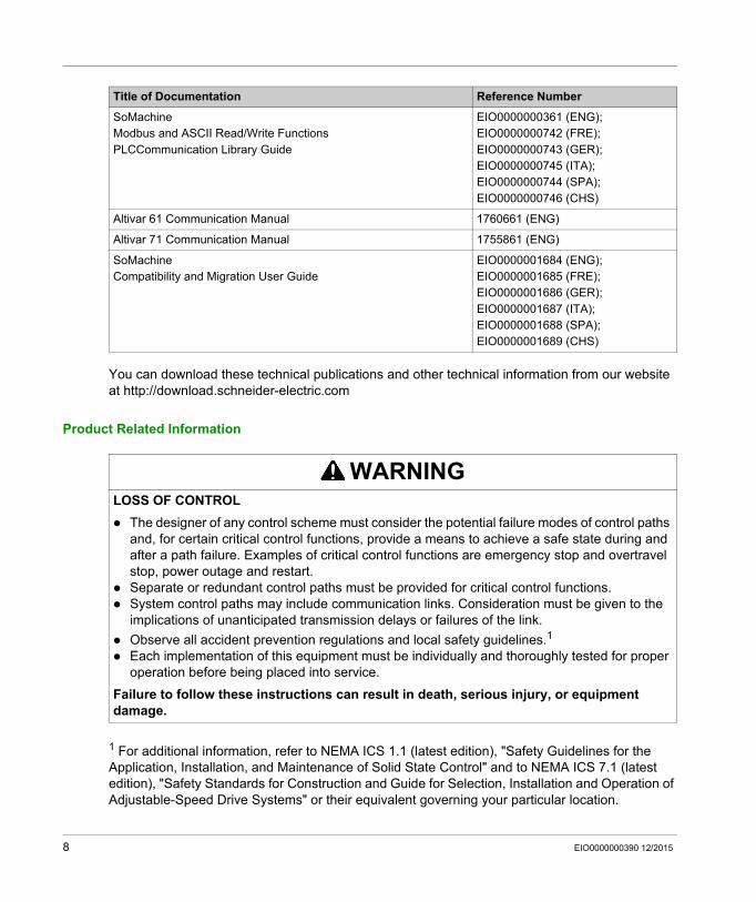
You can download these technical publications and other technical information from our website at http://download.schneider-electric.com
Product Related Information
1 For additional information, refer to NEMA ICS 1.1 (latest edition), "Safety Guidelines for the Application, Installation, and Maintenance of Solid State Control" and to NEMA ICS 7.1 (latest edition), "Safety Standards for Construction and Guide for Selection, Installation and Operation of Adjustable-Speed Drive Systems" or their equivalent governing your particular location.
SoMachineModbus and ASCII Read/Write FunctionsPLCCommunication Library Guide
EIO0000000361 (ENG); EIO0000000742 (FRE); EIO0000000743 (GER); EIO0000000745 (ITA); EIO0000000744 (SPA); EIO0000000746 (CHS)
Altivar 61 Communication Manual 1760661 (ENG)
Altivar 71 Communication Manual 1755861 (ENG)
SoMachineCompatibility and Migration User Guide
EIO0000001684 (ENG); EIO0000001685 (FRE); EIO0000001686 (GER); EIO0000001687 (ITA); EIO0000001688 (SPA); EIO0000001689 (CHS)
Title of Documentation Reference Number
WARNINGLOSS OF CONTROL
The designer of any control scheme must consider the potential failure modes of control paths and, for certain critical control functions, provide a means to achieve a safe state during and after a path failure. Examples of critical control functions are emergency stop and overtravel stop, power outage and restart.
Separate or redundant control paths must be provided for critical control functions. System control paths may include communication links. Consideration must be given to the
implications of unanticipated transmission delays or failures of the link.
Observe all accident prevention regulations and local safety guidelines.1
Each implementation of this equipment must be individually and thoroughly tested for proper operation before being placed into service.
Failure to follow these instructions can result in death, serious injury, or equipment damage.
8 EIO0000000390 12/2015
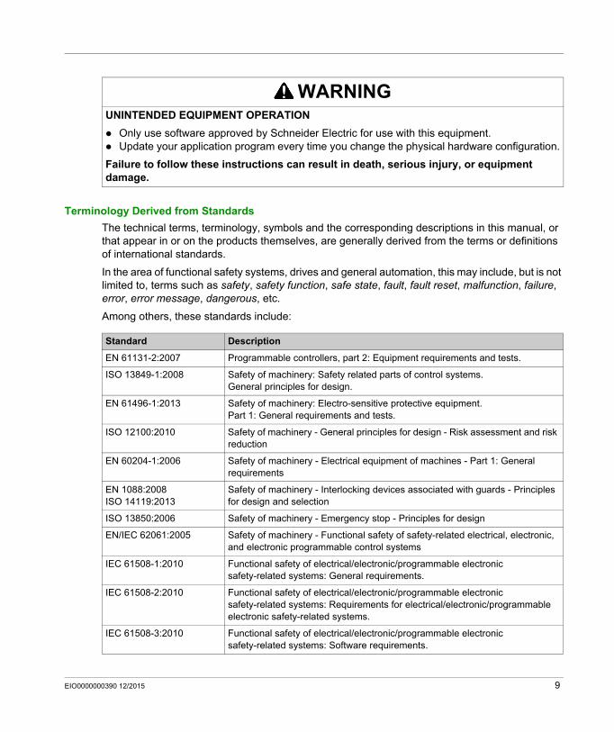
Terminology Derived from Standards
The technical terms, terminology, symbols and the corresponding descriptions in this manual, or that appear in or on the products themselves, are generally derived from the terms or definitions of international standards.
In the area of functional safety systems, drives and general automation, this may include, but is not limited to, terms such as safety, safety function, safe state, fault, fault reset, malfunction, failure, error, error message, dangerous, etc.
Among others, these standards include:
WARNINGUNINTENDED EQUIPMENT OPERATION
Only use software approved by Schneider Electric for use with this equipment. Update your application program every time you change the physical hardware configuration.
Failure to follow these instructions can result in death, serious injury, or equipment damage.
Standard Description
EN 61131-2:2007 Programmable controllers, part 2: Equipment requirements and tests.
ISO 13849-1:2008 Safety of machinery: Safety related parts of control systems.General principles for design.
EN 61496-1:2013 Safety of machinery: Electro-sensitive protective equipment.Part 1: General requirements and tests.
ISO 12100:2010 Safety of machinery - General principles for design - Risk assessment and risk reduction
EN 60204-1:2006 Safety of machinery - Electrical equipment of machines - Part 1: General requirements
EN 1088:2008ISO 14119:2013
Safety of machinery - Interlocking devices associated with guards - Principles for design and selection
ISO 13850:2006 Safety of machinery - Emergency stop - Principles for design
EN/IEC 62061:2005 Safety of machinery - Functional safety of safety-related electrical, electronic, and electronic programmable control systems
IEC 61508-1:2010 Functional safety of electrical/electronic/programmable electronic safety-related systems: General requirements.
IEC 61508-2:2010 Functional safety of electrical/electronic/programmable electronic safety-related systems: Requirements for electrical/electronic/programmable electronic safety-related systems.
IEC 61508-3:2010 Functional safety of electrical/electronic/programmable electronic safety-related systems: Software requirements.
EIO0000000390 12/2015 9
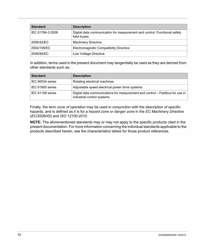
In addition, terms used in the present document may tangentially be used as they are derived from other standards such as:
Finally, the term zone of operation may be used in conjunction with the description of specific hazards, and is defined as it is for a hazard zone or danger zone in the EC Machinery Directive (EC/2006/42) and ISO 12100:2010.
NOTE: The aforementioned standards may or may not apply to the specific products cited in the present documentation. For more information concerning the individual standards applicable to the products described herein, see the characteristics tables for those product references.
IEC 61784-3:2008 Digital data communication for measurement and control: Functional safety field buses.
2006/42/EC Machinery Directive
2004/108/EC Electromagnetic Compatibility Directive
2006/95/EC Low Voltage Directive
Standard Description
IEC 60034 series Rotating electrical machines
IEC 61800 series Adjustable speed electrical power drive systems
IEC 61158 series Digital data communications for measurement and control – Fieldbus for use in industrial control systems
Standard Description
10 EIO0000000390 12/2015
Altivar ATV IMC Drive Controller
Altivar ATV IMC Drive Controller
EIO0000000390 12/2015
About the Altivar ATV IMC Drive Controller
Chapter 1About the Altivar ATV IMC Drive Controller
Altivar ATV IMC Drive Controller
Introduction
The Altivar ATV IMC Drive Controller (ATV IMC: Altivar Integrated Machine Controller) is an option card which can be installed in the Altivar 61 or the Altivar 71 drive. It can be combined with another option card (I/O extension or communication).
NOTE: The ATV IMC is compatible with drives containing a firmware version greater than or equal to V3.3ie43.
Only one Altivar ATV IMC Drive Controller option card can be installed on a drive.
The Altivar ATV IMC Drive Controller is used to adapt the variable speed drive to specific applications by integrating control system functions.
Key Features
The Altivar ATV IMC Drive Controller supports the following IEC61131-3 programming languages using the SoMachine software: IL: Instruction List ST: Structured Text FBD: Function Block Diagram SFC: Sequential Function Chart LD: Ladder Diagram
SoMachine software can also be used to program the controller using CFC (Continuous Function Chart) language.
The Altivar ATV IMC Drive Controller can manage up to 9 tasks.
The Altivar ATV IMC Drive Controller includes the following features using the SoMachine software: 10 digital inputs (2 inputs can be used for 2 counters or 2 inputs can be used for 2 incremental
encoders) 2 analog inputs 6 digital outputs 2 analog outputs A master port for the CANopen bus A mini-USB B port for programming with SoMachine software An Ethernet port to be used for programming with SoMachine software or Modbus TCP
communication.
EIO0000000390 12/2015 11
Altivar ATV IMC Drive Controller
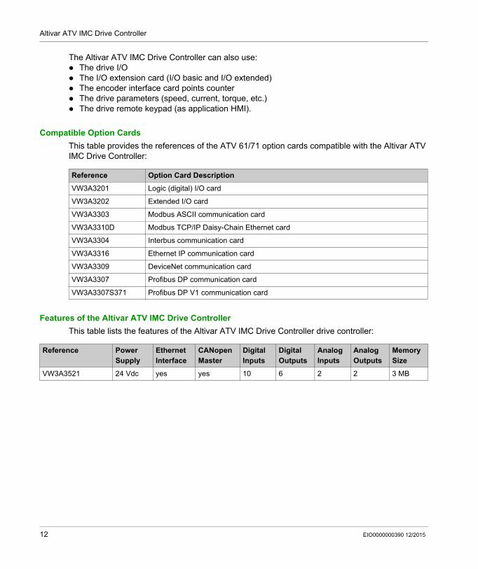
The Altivar ATV IMC Drive Controller can also use: The drive I/O The I/O extension card (I/O basic and I/O extended) The encoder interface card points counter The drive parameters (speed, current, torque, etc.) The drive remote keypad (as application HMI).
Compatible Option Cards
This table provides the references of the ATV 61/71 option cards compatible with the Altivar ATV IMC Drive Controller:
Features of the Altivar ATV IMC Drive Controller
This table lists the features of the Altivar ATV IMC Drive Controller drive controller:
Reference Option Card Description
VW3A3201 Logic (digital) I/O card
VW3A3202 Extended I/O card
VW3A3303 Modbus ASCII communication card
VW3A3310D Modbus TCP/IP Daisy-Chain Ethernet card
VW3A3304 Interbus communication card
VW3A3316 Ethernet IP communication card
VW3A3309 DeviceNet communication card
VW3A3307 Profibus DP communication card
VW3A3307S371 Profibus DP V1 communication card
Reference Power Supply
Ethernet Interface
CANopen Master
Digital Inputs
Digital Outputs
Analog Inputs
Analog Outputs
Memory Size
VW3A3521 24 Vdc yes yes 10 6 2 2 3 MB
12 EIO0000000390 12/2015

Altivar ATV IMC Drive Controller
How to Configure the Controller
EIO0000000390 12/2015
How to Configure the Controller
Chapter 2How to Configure the Controller
How to Configure the Controller
Introduction
First, create a new project or open an existing project in the SoMachine software.
Refer to the SoMachine Programming Guide for information on how to: add a controller to your project add expansion modules to your controller replace an existing controller convert a controller to a different but compatible device
You can also start a new project using the ATV Template (see page 15).
NOTE: Use the ATV Template when starting a new project with an ATV IMC Controller.
EIO0000000390 12/2015 13
How to Configure the Controller
Devices Tree
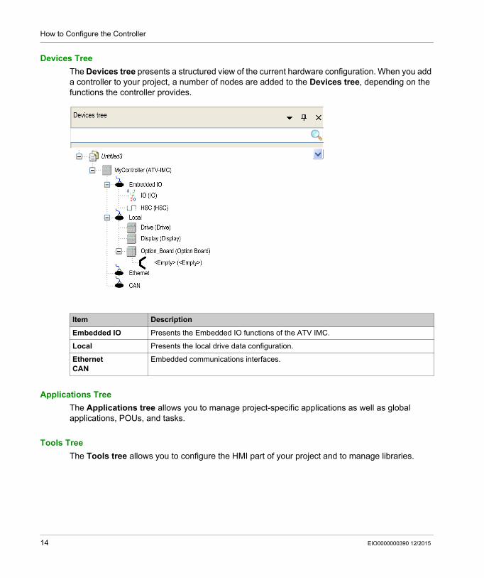
The Devices tree presents a structured view of the current hardware configuration. When you add a controller to your project, a number of nodes are added to the Devices tree, depending on the functions the controller provides.
Applications Tree
The Applications tree allows you to manage project-specific applications as well as global applications, POUs, and tasks.
Tools Tree
The Tools tree allows you to configure the HMI part of your project and to manage libraries.
Item Description
Embedded IO Presents the Embedded IO functions of the ATV IMC.
Local Presents the local drive data configuration.
EthernetCAN
Embedded communications interfaces.
14 EIO0000000390 12/2015
Altivar ATV IMC Drive Controller
Create an ATV IMC Program with the ATV Template
EIO0000000390 12/2015
Create an ATV IMC Program with the ATV Template
Chapter 3Create an ATV IMC Program with the ATV Template
Overview
This chapter describes how to create an Altivar ATV IMC Drive Controller application using the ATV Template program.
What Is in This Chapter?
This chapter contains the following topics:
Topic Page
Create an Altivar ATV IMC Drive Controller Application 16
Overview of the ATV Template 17
Program Organisation Unit (POU) 18
EIO0000000390 12/2015 15
Create an ATV IMC Program with the ATV Template
Create an Altivar ATV IMC Drive Controller Application
ATV Template Usage
When an Altivar ATV IMC Drive Controller is being used on a local drive (a local drive is the drive on which the Altivar ATV IMC Drive Controller card is connected), the ATV template program is a good help for the users less familiar with the Altivar ATV IMC Drive Controller as well as a good support for advanced users to optimize the programming of an Altivar ATV IMC Drive Controller.
This template provides a program structure and the implementation of some functions such as the MANDATORY_AT_EACH_CYCLE function, access to acyclic data, and keypad parameter saves, all of which are necessary when programming an Altivar ATV IMC Drive Controller.
It is a best practice to use the ATV template to start an Altivar ATV IMC Drive Controller application.
Create a Project with the ATV Template
Use SoMachine Central to create a project with the ATV template.
Refer to New Project Assistant - Templates (see SoMachine Central, User Guide) for more information.
16 EIO0000000390 12/2015
Create an ATV IMC Program with the ATV Template
Overview of the ATV Template
Template Diagram
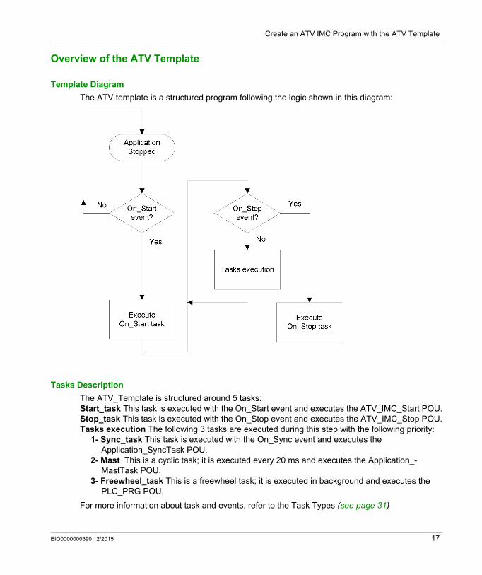
The ATV template is a structured program following the logic shown in this diagram:
Tasks Description
The ATV_Template is structured around 5 tasks:Start_task This task is executed with the On_Start event and executes the ATV_IMC_Start POU.Stop_task This task is executed with the On_Stop event and executes the ATV_IMC_Stop POU.Tasks execution The following 3 tasks are executed during this step with the following priority:
1- Sync_task This task is executed with the On_Sync event and executes the Application_SyncTask POU.
2- Mast This is a cyclic task; it is executed every 20 ms and executes the Application_-MastTask POU.
3- Freewheel_task This is a freewheel task; it is executed in background and executes the PLC_PRG POU.
For more information about task and events, refer to the Task Types (see page 31)
EIO0000000390 12/2015 17
Create an ATV IMC Program with the ATV Template
Program Organisation Unit (POU)
Overview
The ATV Template has several POUs that can be used to manage a local drive and execute the applications you may need.
POUs are displayed in the Applications tree.
POUs are organized in 2 different categories: The POUs executed directly because of a task The POUs executed by the PLC_PRG POU.
POUs Executed by a Task
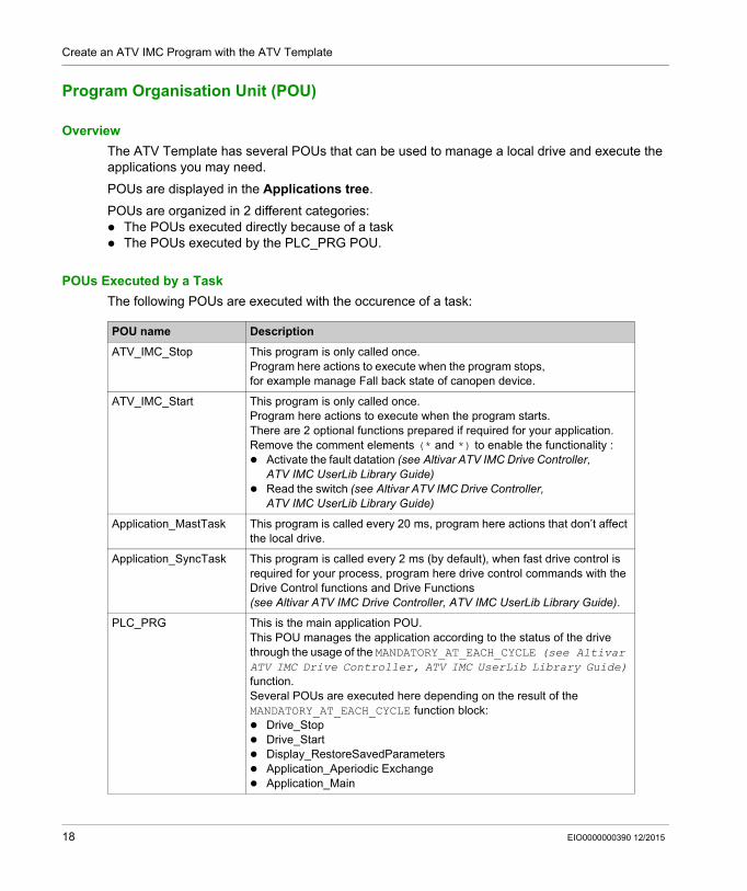
The following POUs are executed with the occurence of a task:
POU name Description
ATV_IMC_Stop This program is only called once.Program here actions to execute when the program stops, for example manage Fall back state of canopen device.
ATV_IMC_Start This program is only called once.Program here actions to execute when the program starts.There are 2 optional functions prepared if required for your application.Remove the comment elements (* and *) to enable the functionality : Activate the fault datation (see Altivar ATV IMC Drive Controller,
ATV IMC UserLib Library Guide) Read the switch (see Altivar ATV IMC Drive Controller,
ATV IMC UserLib Library Guide)
Application_MastTask This program is called every 20 ms, program here actions that don’t affect the local drive.
Application_SyncTask This program is called every 2 ms (by default), when fast drive control is required for your process, program here drive control commands with the Drive Control functions and Drive Functions (see Altivar ATV IMC Drive Controller, ATV IMC UserLib Library Guide).
PLC_PRG This is the main application POU.This POU manages the application according to the status of the drive through the usage of the MANDATORY_AT_EACH_CYCLE (see Altivar ATV IMC Drive Controller, ATV IMC UserLib Library Guide) function.Several POUs are executed here depending on the result of the MANDATORY_AT_EACH_CYCLE function block: Drive_Stop Drive_Start Display_RestoreSavedParameters Application_Aperiodic Exchange Application_Main
18 EIO0000000390 12/2015
Create an ATV IMC Program with the ATV Template
POUs Executed During PLC_PRG
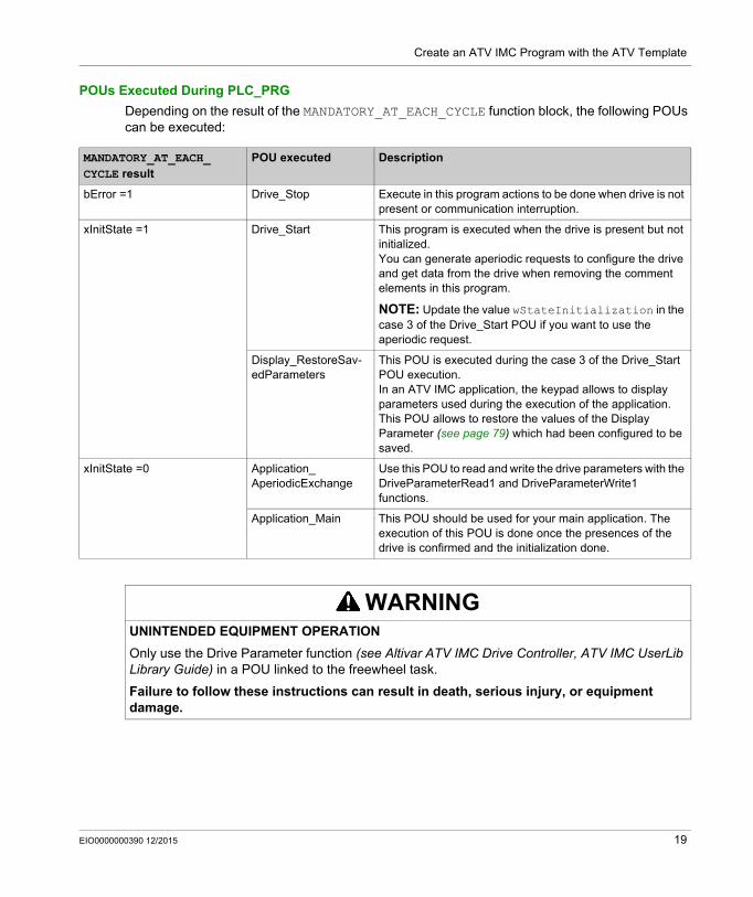
Depending on the result of the MANDATORY_AT_EACH_CYCLE function block, the following POUs can be executed:
MANDATORY_AT_EACH_ CYCLE result
POU executed Description
bError =1 Drive_Stop Execute in this program actions to be done when drive is not present or communication interruption.
xInitState =1 Drive_Start This program is executed when the drive is present but not initialized.You can generate aperiodic requests to configure the drive and get data from the drive when removing the comment elements in this program.
NOTE: Update the value wStateInitialization in the case 3 of the Drive_Start POU if you want to use the aperiodic request.
Display_RestoreSav-edParameters
This POU is executed during the case 3 of the Drive_Start POU execution.In an ATV IMC application, the keypad allows to display parameters used during the execution of the application.This POU allows to restore the values of the Display Parameter (see page 79) which had been configured to be saved.
xInitState =0 Application_ AperiodicExchange
Use this POU to read and write the drive parameters with the DriveParameterRead1 and DriveParameterWrite1 functions.
Application_Main This POU should be used for your main application. The execution of this POU is done once the presences of the drive is confirmed and the initialization done.
WARNINGUNINTENDED EQUIPMENT OPERATION
Only use the Drive Parameter function (see Altivar ATV IMC Drive Controller, ATV IMC UserLib Library Guide) in a POU linked to the freewheel task.
Failure to follow these instructions can result in death, serious injury, or equipment damage.
EIO0000000390 12/2015 19

Create an ATV IMC Program with the ATV Template
20 EIO0000000390 12/2015

Altivar ATV IMC Drive Controller
Libraries
EIO0000000390 12/2015
Libraries
Chapter 4Libraries
Automation Libraries
Introduction
Libraries provide functions, function blocks, data types, and global variables that can be used to develop your project.
The Library Manager of SoMachine provides information about the libraries included in your project and allows you to install new ones. For more information on the Library Manager, refer to the SoMachine Programming Guide.
ATV IMC Drive Controller Libraries
When you select a ATV IMC for your application, ATV IMC automatically loads the following libraries:
Library Name Description
IoStandard CmpIoMgr configuration types, ConfigAccess, Parameters, and help functions: manages the I/Os in the application.
Standard Contains all functions and function blocks which are required matching IEC61131-3 as standard POUs for an IEC programming system. The standard POUs must be tied to the project (standard.library).
Util Analog Monitors, BCD Conversions, Bit/Byte Functions, Controller Datatypes, Function Manipulators, Mathematical Functions, Signals.
ATV IMC SysLib interface with the ATV 71 and 61 local drive
ATV IMC UserLib interface with the ATV 71 and 61 local drive
ATV IMC HSC (see Altivar ATV IMC Drive Controller, High Speed Counting, ATV IMC HSC Library Guide)
Contains function blocks and variables to get information and send commands to the Fast Inputs/Outputs of the ATV IMC controller. These function blocks permit you to implement HSC (High Speed Counting) functions on the Fast Inputs/Outputs of the ATV IMC controller.
ATV IMC PLCSystem (see Altivar ATV IMC Drive Controller, System Functions and Variables, ATV-IMC PLCSystem Library Guide)
Contains functions and variables to get information and send commands to the controller system.
EIO0000000390 12/2015 21

Libraries
22 EIO0000000390 12/2015
Altivar ATV IMC Drive Controller
Supported Standard Data Types
EIO0000000390 12/2015
Supported Standard Data Types
Chapter 5Supported Standard Data Types
Supported Standard Data Types
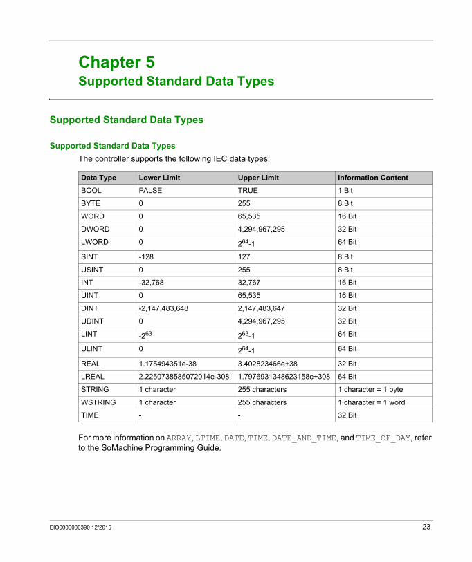
Supported Standard Data Types
The controller supports the following IEC data types:
For more information on ARRAY, LTIME, DATE, TIME, DATE_AND_TIME, and TIME_OF_DAY, refer to the SoMachine Programming Guide.
Data Type Lower Limit Upper Limit Information Content
BOOL FALSE TRUE 1 Bit
BYTE 0 255 8 Bit
WORD 0 65,535 16 Bit
DWORD 0 4,294,967,295 32 Bit
LWORD 0 264-1 64 Bit
SINT -128 127 8 Bit
USINT 0 255 8 Bit
INT -32,768 32,767 16 Bit
UINT 0 65,535 16 Bit
DINT -2,147,483,648 2,147,483,647 32 Bit
UDINT 0 4,294,967,295 32 Bit
LINT -263 263-1 64 Bit
ULINT 0 264-1 64 Bit
REAL 1.175494351e-38 3.402823466e+38 32 Bit
LREAL 2.2250738585072014e-308 1.7976931348623158e+308 64 Bit
STRING 1 character 255 characters 1 character = 1 byte
WSTRING 1 character 255 characters 1 character = 1 word
TIME - - 32 Bit
EIO0000000390 12/2015 23

Supported Standard Data Types
24 EIO0000000390 12/2015
Altivar ATV IMC Drive Controller
Memory Mapping
EIO0000000390 12/2015
Memory Mapping
Chapter 6Memory Mapping
Memory Organization
Introduction
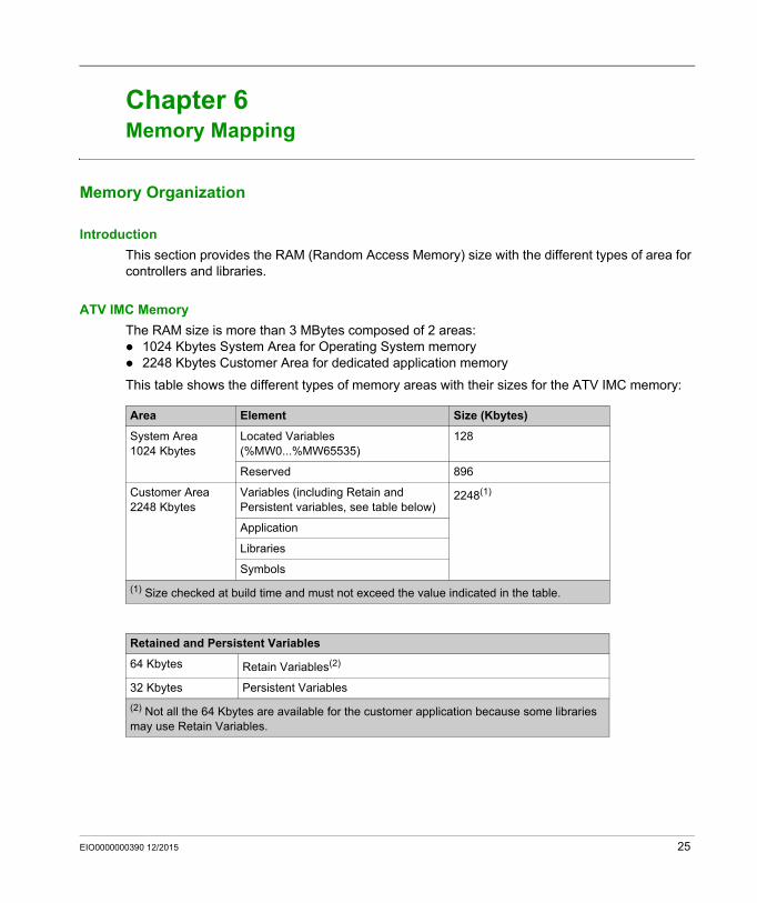
This section provides the RAM (Random Access Memory) size with the different types of area for controllers and libraries.
ATV IMC Memory
The RAM size is more than 3 MBytes composed of 2 areas: 1024 Kbytes System Area for Operating System memory 2248 Kbytes Customer Area for dedicated application memory
This table shows the different types of memory areas with their sizes for the ATV IMC memory:
Area Element Size (Kbytes)
System Area 1024 Kbytes
Located Variables(%MW0...%MW65535)
128
Reserved 896
Customer Area2248 Kbytes
Variables (including Retain and Persistent variables, see table below)
2248(1)
Application
Libraries
Symbols
(1) Size checked at build time and must not exceed the value indicated in the table.
Retained and Persistent Variables
64 Kbytes Retain Variables(2)
32 Kbytes Persistent Variables
(2) Not all the 64 Kbytes are available for the customer application because some libraries may use Retain Variables.
EIO0000000390 12/2015 25

Memory Mapping
Memory Addressing
This table describes the memory addressing for the address size Double Word (%MD), Word (%MW), Byte (%MB), and Bit (%MX).
Examples of overlap memory of ranges:
%MD0 contains %MB0 (...) %MB3, %MW0 contains %MB0 and %MB1, %MW1 contains %MB2 and %MB3.
Library Size
NOTE: The maximum number of CANopen nodes is 16.
Double Words Words Bytes Bits
%MD0 %MW0 %MB0 %MX0.7 ... %MX0.0
%MB1 %MX1.7 ... %MX1.0
%MW1 %MB2 %MX2.7 ... %MX2.0
%MB3 %MX3.7 ... %MX3.0
%MD1 %MW2 %MB4 %MX4.7 ... %MX4.0
%MB5 %MX5.7 ... %MX5.0
%MW3 %MB6 %MX6.7 ... %MX6.0
%MB7 %MX7.7 ... %MX7.0
%MD2 %MW4 %MB8 %MX8.7 ... %MX8.0
... ... ... ...
... ... ... ... ...
... ... ... ...
Library Name Average Size Comment
3S CANopenStack 86 Kbyte Depends on the functions used. Each CANopen node increases the memory size of 11 Kbyte.
26 EIO0000000390 12/2015
Altivar ATV IMC Drive Controller
Tasks
EIO0000000390 12/2015
Tasks
Chapter 7Tasks
Introduction
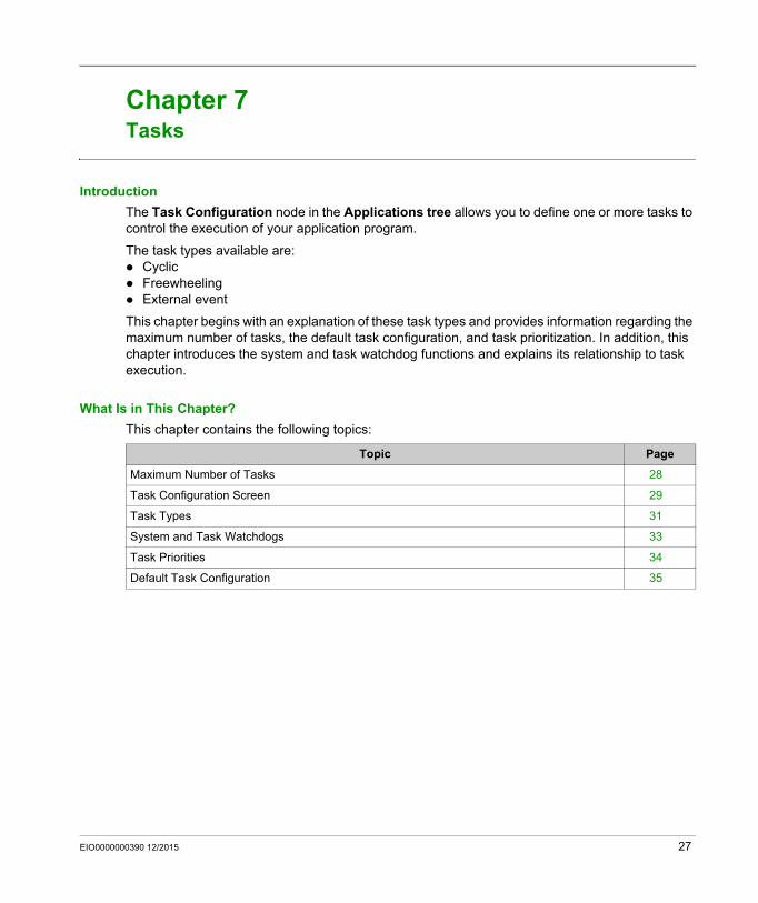
The Task Configuration node in the Applications tree allows you to define one or more tasks to control the execution of your application program.
The task types available are: Cyclic Freewheeling External event
This chapter begins with an explanation of these task types and provides information regarding the maximum number of tasks, the default task configuration, and task prioritization. In addition, this chapter introduces the system and task watchdog functions and explains its relationship to task execution.
What Is in This Chapter?
This chapter contains the following topics:
Topic Page
Maximum Number of Tasks 28
Task Configuration Screen 29
Task Types 31
System and Task Watchdogs 33
Task Priorities 34
Default Task Configuration 35
EIO0000000390 12/2015 27
Tasks
Maximum Number of Tasks
Maximum Number of Tasks
The maximum number of tasks you can define for the ATV IMC are: Total number of tasks = 9 Cyclic tasks = 3 Freewheeling tasks = 1 External Event tasks = 5
Special Considerations for Freewheeling
A Freewheeling task (see page 32) does not have a fixed duration. In Freewheeling mode, each task scan starts when the previous scan has been completed and after a period of system processing (30% of the total duration of the Freewheeling task). If the system processing period is reduced to less than 15% for more than 3 seconds due to interruptions by other tasks, a system error is detected. For more information, refer to the System Watchdog (see page 33).
NOTE: You may wish to avoid using a Freewheeling task in a multi-task application when some high priority and time-consuming tasks are running. Doing so may provoke a task Watchdog Timeout. You should not assign CANopen to a freewheeling task. CANopen should be assigned to a cyclic task.
28 EIO0000000390 12/2015
Tasks
Task Configuration Screen
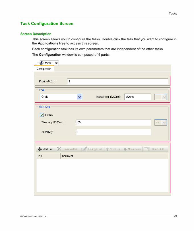
Screen Description
This screen allows you to configure the tasks. Double-click the task that you want to configure in the Applications tree to access this screen.
Each configuration task has its own parameters that are independent of the other tasks.
The Configuration window is composed of 4 parts:
EIO0000000390 12/2015 29
Tasks
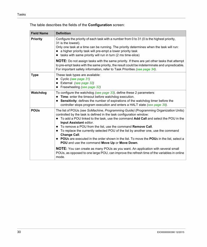
The table describes the fields of the Configuration screen:
Field Name Definition
Priority Configure the priority of each task with a number from 0 to 31 (0 is the highest priority, 31 is the lowest).Only one task at a time can be running. The priority determines when the task will run: a higher priority task will pre-empt a lower priority task tasks with same priority will run in turn (2 ms time-slice)
NOTE: Do not assign tasks with the same priority. If there are yet other tasks that attempt to pre-empt tasks with the same priority, the result could be indeterminate and unpredicable. For important safety information, refer to Task Priorities (see page 34).
Type These task types are available: Cyclic (see page 31) External (see page 32) Freewheeling (see page 32)
Watchdog To configure the watchdog (see page 33), define these 2 parameters: Time: enter the timeout before watchdog execution. Sensitivity: defines the number of expirations of the watchdog timer before the
controller stops program execution and enters a HALT state (see page 39).
POUs The list of POUs (see SoMachine, Programming Guide) (Programming Organization Units) controlled by the task is defined in the task configuration window: To add a POU linked to the task, use the command Add Call and select the POU in the
Input Assistant editor. To remove a POU from the list, use the command Remove Call. To replace the currently selected POU of the list by another one, use the command
Change Call. POUs are executed in the order shown in the list. To move the POUs in the list, select a
POU and use the command Move Up or Move Down.
NOTE: You can create as many POUs as you want. An application with several small POUs, as opposed to one large POU, can improve the refresh time of the variables in online mode.
30 EIO0000000390 12/2015
Tasks
Task Types
Introduction
The following section describes the various task types available for your program, along with a description of the task type characteristics.
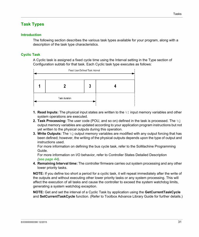
Cyclic Task
A Cyclic task is assigned a fixed cycle time using the Interval setting in the Type section of Configuration subtab for that task. Each Cyclic task type executes as follows:
1. Read Inputs: The physical input states are written to the %I input memory variables and other system operations are executed.
2. Task Processing: The user code (POU, and so on) defined in the task is processed. The %Q output memory variables are updated according to your application program instructions but not yet written to the physical outputs during this operation.
3. Write Outputs: The %Q output memory variables are modified with any output forcing that has been defined; however, the writing of the physical outputs depends upon the type of output and instructions used. For more information on defining the bus cycle task, refer to the SoMachine Programming Guide.For more information on I/O behavior, refer to Controller States Detailed Description (see page 44).
4. Remaining Interval time: The controller firmware carries out system processing and any other lower priority tasks.
NOTE: If you define too short a period for a cyclic task, it will repeat immediately after the write of the outputs and without executing other lower priority tasks or any system processing. This will affect the execution of all tasks and cause the controller to exceed the system watchdog limits, generating a system watchdog exception.
NOTE: Get and set the interval of a Cyclic Task by application using the GetCurrentTaskCycle and SetCurrentTaskCycle function. (Refer to Toolbox Advance Library Guide for further details.)
EIO0000000390 12/2015 31

Tasks
Freewheeling Task
A Freewheeling task does not have a fixed duration. In Freewheeling mode, each task scan begins when the previous scan has been completed and after a short period of system processing. Each Freewheeling task type executes as follows:
1. Read Inputs: The physical input states are written to the %I input memory variables and other system operations are executed.
2. Task Processing: The user code (POU, and so on) defined in the task is processed. The %Q output memory variables are updated according to your application program instructions but not yet written to the physical outputs during this operation.
3. Write Outputs: The %Q output memory variables are modified with any output forcing that has been defined; however, the writing of the physical outputs depends upon the type of output and instructions used.For more information on defining the bus cycle task, refer to the SoMachine Programming Guide.For more information on I/O behavior, refer to Controller States Detailed Description (see page 44).
4. System Processing: The controller firmware carries out system processing and any other lower priority tasks (for example: HTTP management, Ethernet management, parameters management).
External Event Task
This type of task is event-driven and is initiated by the detection of a hardware or hardware-related function event. It starts when the event occurs unless pre-empted by a higher priority task. In that case, the External Event task will start as dictated by the task priority assignments.
NOTE: It is not possible to assign more than one task to a single external event.
You can trigger a task associated to an external event through: A rising edge on a Fast input (on_LI53 and on_LI54) The start/stop of the controller program (on_Start and on_Stop) An external event periodically produced by the local drive (on_Sync)
NOTE: You can configure the on_Sync period with the SyncTaskPeriodSet function (see Altivar ATV IMC Drive Controller, ATV IMC UserLib Library Guide) (default value is 2 ms).
32 EIO0000000390 12/2015

Tasks
System and Task Watchdogs
Introduction
Two types of watchdog functionality are implemented for the ATV IMC:
System Watchdogs: These watchdogs are defined in and managed by the controller firmware. These are not configurable by the user.
Task Watchdogs: These watchdogs are optional watchdogs that you can define for each task. These are managed by your application program and are configurable in SoMachine.
System Watchdogs
Two system watchdogs are defined for the ATV IMC. They are managed by the controller firmware and are therefore sometimes referred to as hardware watchdogs in the SoMachine online help. When the system watchdog exceeds its threshold conditions, an error is detected.
The threshold conditions for the 2 system watchdogs are defined as follows: If all of the tasks require more than 85% of the processor resources for more than 3 seconds, a
system error is detected. The controller enters the EMPTY state. If the lowest priority task of the system is not executed during an interval of 20 seconds, a
system error is detected. The controller responds with an automatic reboot into the EMPTY state.
NOTE: System watchdogs are not configurable by the user.
Task Watchdogs
SoMachine allows you to configure an optional task watchdog for every task defined in your application program. (Task watchdogs are sometimes also referred to as software watchdogs or control timers in the SoMachine online help). When one of your defined task watchdogs reaches its threshold condition, an application error is detected and the controller enters the HALT state.
When defining a task watchdog, the following options are available: Time: This defines the allowable maximum execution time for a task. When a task takes longer
than this, the controller will report a task watchdog exception. Sensitivity: The sensitivity field defines the number of task watchdog exceptions that must
occur before the controller detects an application error.
To access the configuration of a task watchdog, double-click the Task in the Applications tree.
NOTE: For more information on watchdogs, refer to SoMachine Programming Guide.
EIO0000000390 12/2015 33
Tasks
Task Priorities
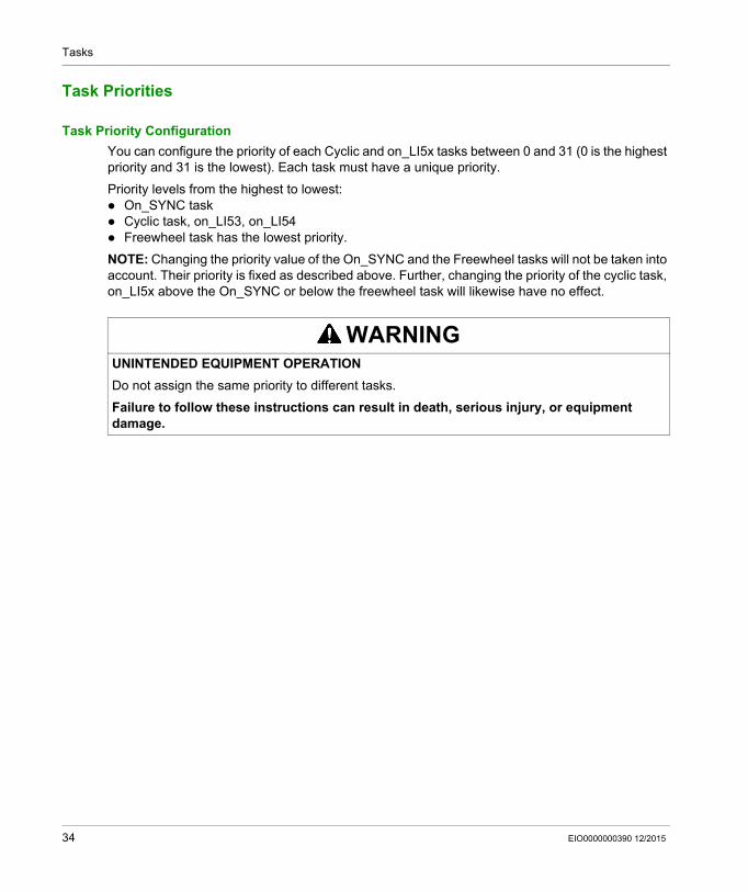
Task Priority Configuration
You can configure the priority of each Cyclic and on_LI5x tasks between 0 and 31 (0 is the highest priority and 31 is the lowest). Each task must have a unique priority.
Priority levels from the highest to lowest: On_SYNC task Cyclic task, on_LI53, on_LI54 Freewheel task has the lowest priority.
NOTE: Changing the priority value of the On_SYNC and the Freewheel tasks will not be taken into account. Their priority is fixed as described above. Further, changing the priority of the cyclic task, on_LI5x above the On_SYNC or below the freewheel task will likewise have no effect.
WARNINGUNINTENDED EQUIPMENT OPERATION
Do not assign the same priority to different tasks.
Failure to follow these instructions can result in death, serious injury, or equipment damage.
34 EIO0000000390 12/2015
Tasks
Default Task Configuration
Default Task Configuration
The MAST task can be configured in Freewheeling or Cyclic mode. The MAST task is automatically created by default in Cyclic mode. Its preset priority is medium (15), its preset interval is 20 ms, and its task watchdog service is activated with a time of 100 ms and a sensitivity of 1. Refer to Task Priorities (see page 34) for more information on priority settings. Refer to System and Task Watchdogs (see page 33) for more information on watchdogs.
Designing an efficient application program is important in systems approaching the maximum number of tasks. In such an application, it can be difficult to keep the resource utilization below the system watchdog threshold. If priority reassignments alone are not sufficient to remain below the threshold, some lower priority tasks can be made to use fewer system resources if the SysTaskWaitSleep function is added to those tasks. For more information about this function, see the optional SysTask library of the system / SysLibs category of libraries.
NOTE: Do not delete or change the name of the MAST task. If you do so, SoMachine detects an error when you attempt to build the application, and you will not be able to download it to the controller.
EIO0000000390 12/2015 35

Tasks
36 EIO0000000390 12/2015
Altivar ATV IMC Drive Controller
Controller States and Behaviors
EIO0000000390 12/2015
Controller States and Behaviors
Chapter 8Controller States and Behaviors
Introduction
This chapter provides you with information on controller states, state transitions, and behaviors in response to system events. It begins with a detailed controller state diagram and a description of each state. It then defines the relationship of output states to controller states before explaining the commands and events that result in state transitions. It concludes with information about Remanent variables and the effect of SoMachine task programming options on the behavior of your system.
What Is in This Chapter?
This chapter contains the following sections:
Section Topic Page
8.1 Controller State Diagram 38
8.2 Controller States Description 44
8.3 State Transitions and System Events 48
EIO0000000390 12/2015 37

Controller States and Behaviors
Controller State Diagram
Section 8.1Controller State Diagram
38 EIO0000000390 12/2015
Controller States and Behaviors
Controller State Diagram
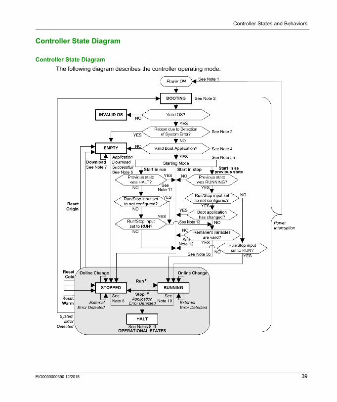
Controller State Diagram
The following diagram describes the controller operating mode:
EIO0000000390 12/2015 39
Controller States and Behaviors
Legend: Controller states are indicated in ALL-CAPS BOLD User and application commands are indicated in Bold System events are indicated in Italics Decisions, decision results and general information are indicated in normal text
(1) For details on STOPPED to RUNNING state transition, refer to Run Command (see page 52).
(2) For details on RUNNING to STOPPED state transition, refer to Stop Command (see page 52).
Note 1
The Power Cycle (Power Interruption followed by a Power ON) deletes all output forcing settings. Refer to Controller State and Output Behavior (see page 49) for further details.
Note 2
There is a 1-2 second delay between entering the BOOTING state and the LED indication of this state. The boot process can take up to 5 seconds under normal conditions. The outputs will assume their initialization states.
Note 3
In some cases, when a system error is detected, it will cause the controller to automatically reboot into the EMPTY state as if no Boot application were present in the Flash memory. However, the Boot application is not actually deleted from the Flash memory.
Note 4
The application is loaded into RAM after verification of a valid Boot application.
During the load of the boot application, a Check context test occurs to assure that the Remanent variables are valid. If the Check context test is invalid, the boot application will load but the controller will assume STOPPED state (see page 55).
Note 5a
The Starting Mode is set in the PLC settings tab of the Controller Device Editor.
Note 5b
When a power interruption occurs, the controller reassumes the state before the power interruption. However, depending on the source of power of the ATV IMC drive controller and whether you configured the Run/Stop input, the ATV IMC drive controller may interpret the loss of power to the Run/Stop input as a Stop command. In this case, when power returns the controller will assume the STOPPED state.
40 EIO0000000390 12/2015

Controller States and Behaviors
Note 6
During a successful application download, the following events occur: The application is loaded directly into RAM. By default, the Boot application is created and saved into the Flash memory.
Note 7
The default behavior after downloading an application program is for the controller to enter the STOPPED state irrespective of the Run/Stop input setting or the last controller state before the download.
However, there are two important considerations in this regard:Online Change: An online change (partial download) initiated while the controller is in the
RUNNING state returns the controller to the RUNNING state if successful and provided the Run/Stop input is configured and set to Run. Before using the Login with online change option, test the changes to your application program in a virtual or non-production environment and confirm that the controller and attached equipment assume their expected conditions in the RUNNING state.
NOTE: Online changes to your program are not automatically written to the Boot application, and will be overwritten by the existing Boot application at the next reboot. If you wish your changes to persist through a reboot, manually update the Boot application by selecting Create boot application in the Online menu (the controller must be in the STOPPED state to achieve this operation).
Multiple Download: SoMachine has a feature that allows you to perform a full application download to multiple targets on your network or fieldbus. One of the default options when you select the Multiple Download... command is the Start all applications after download or online change option, which restarts all download targets in the RUNNING state, provided their respective Run/Stop inputs are commanding the RUNNING state, but irrespective of their last controller state before the multiple download was initiated. Deselect this option if you do not want all targeted controllers to restart in the RUNNING state. In addition, before using the Multiple Download option, test the changes to your application program in a virtual or non-production environment and confirm that the targeted controllers and attached equipment assume their expected conditions in the RUNNING state.
WARNINGUNINTENDED EQUIPMENT OPERATION
Always verify that online changes to a RUNNING application program operate as expected before downloading them to controllers.
Failure to follow these instructions can result in death, serious injury, or equipment damage.
EIO0000000390 12/2015 41
Controller States and Behaviors
NOTE: During a multiple download, unlike a normal download, SoMachine does not offer the option to create a Boot application. You can manually create a Boot application at any time by selecting Create boot application in the Online menu on all targeted controllers (the controller must be in the STOPPED state for this operation).
Note 8
The SoMachine software platform allows many powerful options for managing task execution and output conditions while the controller is in the STOPPED or HALT states. Refer to Controller States Description (see page 44) for further details.
Note 9
To exit the HALT state it is necessary to issue one of the Reset commands (Reset Warm, Reset Cold, Reset Origin), download an application or cycle power.
In case of non recoverable event (system watchdog or internal detected error), a cycle power is mandatory.
Note 10
The RUNNING state has two exception conditions.
They are: RUNNING with External Detected Error: this exception condition is indicated by the MS Status
LED, which displays solid green with 1 red flash. You may exit this state by clearing the external detected error. No controller commands are required.
RUNNING with Breakpoint: this exception condition is indicated by the MS Status LED, which displays 3 green flashes. Refer to Controller States Description (see page 44) for further details.
Note 11
When Starting Mode is set to Start in run and if the Run/Stop input is not configured, the controller will reboot in STOPPED state. A second reboot will be necessary to set the controller in RUNNING state.
WARNINGUNINTENDED EQUIPMENT OPERATION
Always verify that your application program will operate as expected for all targeted controllers and equipment before issuing the "Multiple Download…" command with the "Start all applications after download or online change" option selected.
Failure to follow these instructions can result in death, serious injury, or equipment damage.
42 EIO0000000390 12/2015
Controller States and Behaviors
Note 12
Remanent variables can be invalid if battery is not present for example.
Note 13
The boot application can be different from the application loaded. It can happen when the boot application was downloaded through USB Key, FTP or File Transfer or when an online change was performed without creating the boot application.
EIO0000000390 12/2015 43
Controller States and Behaviors
Controller States Description
Section 8.2Controller States Description
Controller States Description
Introduction
This section provides a detailed description of the controller states.
(1) The controller states can be read in the PLC_R.i_wStatus system variable of the ATV IMC PLCSystem (see Altivar ATV IMC Drive Controller, System Functions and Variables, ATV-IMC PLCSystem Library Guide)
WARNINGUNINTENDED EQUIPMENT OPERATION
Never assume that your controller is in a certain controller state before commanding a change of state, configuring your controller options, uploading a program, or modifying the physical configuration of the controller and its connected equipment.
Before performing any of these operations, consider the effect on all connected equipment. Before acting on a controller, always positively confirm the controller state by viewing its LEDs,
confirming the condition of the Run/Stop input, verifying the presence of output forcing, and
reviewing the controller status information via SoMachine.(1)
Failure to follow these instructions can result in death, serious injury, or equipment damage.
44 EIO0000000390 12/2015
Controller States and Behaviors
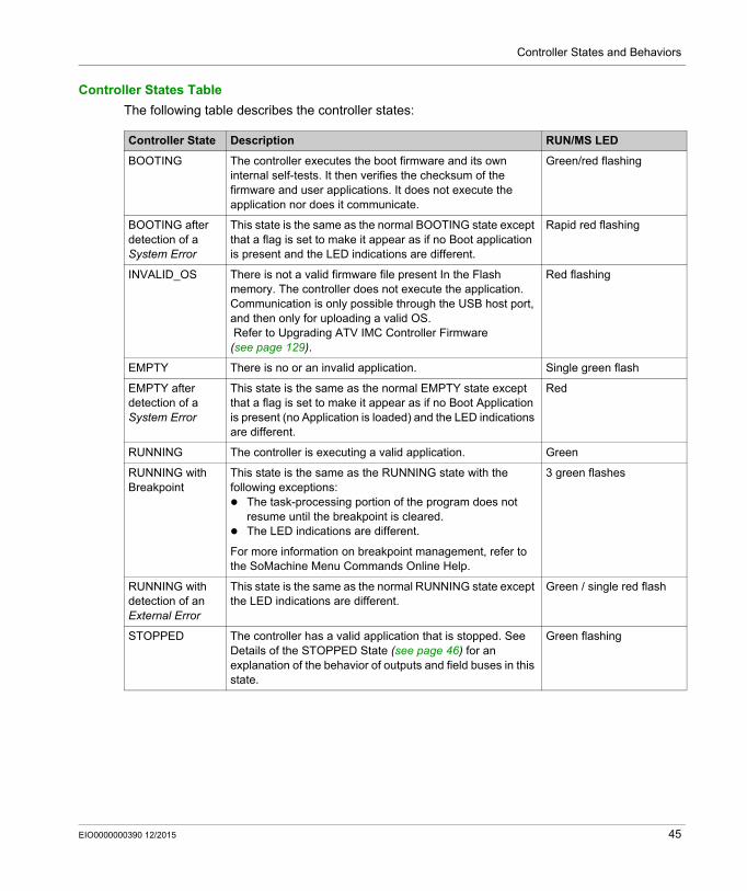
Controller States Table
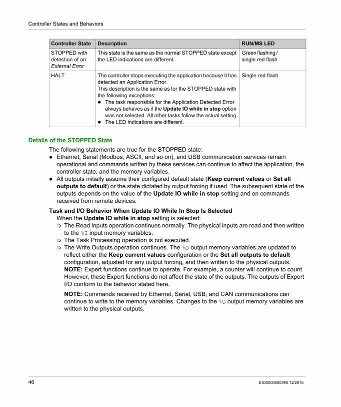
The following table describes the controller states:
Controller State Description RUN/MS LED
BOOTING The controller executes the boot firmware and its own internal self-tests. It then verifies the checksum of the firmware and user applications. It does not execute the application nor does it communicate.
Green/red flashing
BOOTING after detection of a System Error
This state is the same as the normal BOOTING state except that a flag is set to make it appear as if no Boot application is present and the LED indications are different.
Rapid red flashing
INVALID_OS There is not a valid firmware file present In the Flash memory. The controller does not execute the application. Communication is only possible through the USB host port, and then only for uploading a valid OS. Refer to Upgrading ATV IMC Controller Firmware (see page 129).
Red flashing
EMPTY There is no or an invalid application. Single green flash
EMPTY after detection of a System Error
This state is the same as the normal EMPTY state except that a flag is set to make it appear as if no Boot Application is present (no Application is loaded) and the LED indications are different.
Red
RUNNING The controller is executing a valid application. Green
RUNNING with Breakpoint
This state is the same as the RUNNING state with the following exceptions: The task-processing portion of the program does not
resume until the breakpoint is cleared. The LED indications are different.
For more information on breakpoint management, refer to the SoMachine Menu Commands Online Help.
3 green flashes
RUNNING with detection of an External Error
This state is the same as the normal RUNNING state except the LED indications are different.
Green / single red flash
STOPPED The controller has a valid application that is stopped. See Details of the STOPPED State (see page 46) for an explanation of the behavior of outputs and field buses in this state.
Green flashing
EIO0000000390 12/2015 45
Controller States and Behaviors
Details of the STOPPED State
The following statements are true for the STOPPED state: Ethernet, Serial (Modbus, ASCII, and so on), and USB communication services remain
operational and commands written by these services can continue to affect the application, the controller state, and the memory variables.
All outputs initially assume their configured default state (Keep current values or Set all outputs to default) or the state dictated by output forcing if used. The subsequent state of the outputs depends on the value of the Update IO while in stop setting and on commands received from remote devices.
Task and I/O Behavior When Update IO While In Stop Is Selected When the Update IO while in stop setting is selected: The Read Inputs operation continues normally. The physical inputs are read and then written
to the %I input memory variables. The Task Processing operation is not executed. The Write Outputs operation continues. The %Q output memory variables are updated to
reflect either the Keep current values configuration or the Set all outputs to default configuration, adjusted for any output forcing, and then written to the physical outputs.NOTE: Expert functions continue to operate. For example, a counter will continue to count. However, these Expert functions do not affect the state of the outputs. The outputs of Expert I/O conform to the behavior stated here.
NOTE: Commands received by Ethernet, Serial, USB, and CAN communications can continue to write to the memory variables. Changes to the %Q output memory variables are written to the physical outputs.
STOPPED with detection of an External Error
This state is the same as the normal STOPPED state except the LED indications are different.
Green flashing / single red flash
HALT The controller stops executing the application because it has detected an Application Error.This description is the same as for the STOPPED state with the following exceptions: The task responsible for the Application Detected Error
always behaves as if the Update IO while in stop option was not selected. All other tasks follow the actual setting.
The LED indications are different.
Single red flash
Controller State Description RUN/MS LED
46 EIO0000000390 12/2015

Controller States and Behaviors
CAN Behavior When Update IO While In Stop Is Selected The following is true for the CAN buses when the Update IO while in stop setting is selected: The CAN bus remains fully operational. Devices on the CAN bus continue to perceive the
presence of a functional CAN Master. TPDO and RPDO continue to be exchanged. The optional SDO, if configured, continue to be exchanged. The Heartbeat and Node Guarding functions, if configured, continue to operate. If the Behaviour for outputs in Stop field is set to Keep current values, the TPDOs
continue to be issued with the last actual values. If the Behaviour for outputs in Stop field is Set all outputs to default the last actual values
are updated to the default values and subsequent TPDOs are issued with these default values.
Task and I/O Behavior When Update IO While In Stop Is Not Selected When the Update IO while in stop setting is not selected, the controller sets the I/O to either the Keep current values or Set all outputs to default condition (as adjusted for output forcing if used). After this, the following becomes true: The Read Inputs operation ceases. The %I input memory variablea are frozen at their last
values. The Task Processing operation is not executed. The Write Outputs operation ceases. The %Q output memory variables can be updated via
the Ethernet, Serial, and USB connections. However, the physical outputs are unaffected and retain the state specified by the configuration options.NOTE: Expert functions cease operating. For example, a counter will be stopped.
CAN Behavior When Update IO While In Stop Is Not Selected The following is true for the CAN buses when the Update IO while in stop setting is not selected: The CAN Master ceases communications. Devices on the CAN bus assume their configured
fallback states. TPDO and RPDO exchanges cease. Optional SDO, if configured, exchanges cease. The Heartbeat and Node Guarding functions, if configured, stop. The current or default values, as appropriate, are written to the TPDOs and sent once before
stopping the CAN Master.
EIO0000000390 12/2015 47

Controller States and Behaviors
State Transitions and System Events
Section 8.3State Transitions and System Events
Overview
This section begins with an explanation of the output states possible for the controller. It then presents the system commands used to transition between controller states and the system events that can also affect these states. It concludes with an explanation of the Remanent variables, and the circumstances under which different variables and data types are retained through state transitions.
What Is in This Section?
This section contains the following topics:
Topic Page
Controller States and Output Behavior 49
Commanding State Transitions 52
Error Detection, Types, and Management 58
Remanent Variables 59
48 EIO0000000390 12/2015
Controller States and Behaviors
Controller States and Output Behavior
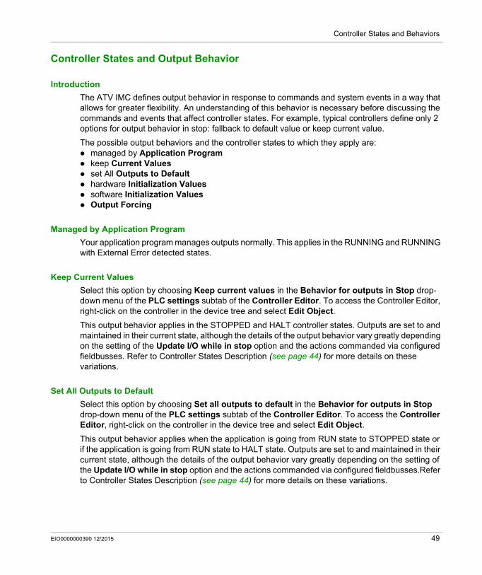
Introduction
The ATV IMC defines output behavior in response to commands and system events in a way that allows for greater flexibility. An understanding of this behavior is necessary before discussing the commands and events that affect controller states. For example, typical controllers define only 2 options for output behavior in stop: fallback to default value or keep current value.
The possible output behaviors and the controller states to which they apply are: managed by Application Program keep Current Values set All Outputs to Default hardware Initialization Values software Initialization Values Output Forcing
Managed by Application Program
Your application program manages outputs normally. This applies in the RUNNING and RUNNING with External Error detected states.
Keep Current Values
Select this option by choosing Keep current values in the Behavior for outputs in Stop drop-down menu of the PLC settings subtab of the Controller Editor. To access the Controller Editor, right-click on the controller in the device tree and select Edit Object.
This output behavior applies in the STOPPED and HALT controller states. Outputs are set to and maintained in their current state, although the details of the output behavior vary greatly depending on the setting of the Update I/O while in stop option and the actions commanded via configured fieldbusses. Refer to Controller States Description (see page 44) for more details on these variations.
Set All Outputs to Default
Select this option by choosing Set all outputs to default in the Behavior for outputs in Stop drop-down menu of the PLC settings subtab of the Controller Editor. To access the Controller Editor, right-click on the controller in the device tree and select Edit Object.
This output behavior applies when the application is going from RUN state to STOPPED state or if the application is going from RUN state to HALT state. Outputs are set to and maintained in their current state, although the details of the output behavior vary greatly depending on the setting of the Update I/O while in stop option and the actions commanded via configured fieldbusses.Refer to Controller States Description (see page 44) for more details on these variations.
EIO0000000390 12/2015 49

Controller States and Behaviors
Hardware Initialization Values
This output state applies in the BOOTING, EMPTY (following power cycle with no boot application or after the detection of a system error), and INVALID_OS states.
In the initialization state, analog, transistor, and relay outputs assume the following values: For an analog output: Z (high impedance) For a fast transistor output: Z (high impedance) For a regular transistor output: 0 Vdc For a relay output: Open
Software Initialization Values
This output state applies when downloading or when resetting the application. It applies at the end of the download or at the end of a reset warm or cold.
The software Initialization Values are the initialization values of outputs images (%I, %Q, or variables mapped on %I or %Q).
By default, they are set to 0 but it is possible to map the I/O in a GVL and assign to the outputs a value different from 0.
Output Forcing
The controller allows you to force the state of selected outputs to a defined value for the purposes of system testing, commissioning, and maintenance.
You are only able to force the value of an output while your controller is connected to SoMachine.
To do so, use the Force values command in the Debug menu.
Output forcing overrides all other commands to an output irrespective of the task programming that is being executed.
When you logout of SoMachine when output forcing has been defined, you are presented with the option to retain output forcing settings. If you select this option, the output forcing continues to control the state of the selected outputs until you download an application or use one of the Reset commands.
When the option Update I/O while in stop, if supported by your controller, is checked (default state), the forced outputs keep the forcing value even when the logic controller is in STOP.
50 EIO0000000390 12/2015
Controller States and Behaviors
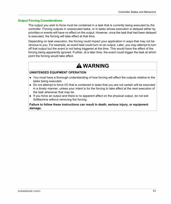
Output Forcing Considerations
The output you wish to force must be contained in a task that is currently being executed by the controller. Forcing outputs in unexecuted tasks, or in tasks whose execution is delayed either by priorities or events will have no effect on the output. However, once the task that had been delayed is executed, the forcing will take effect at that time.
Depending on task execution, the forcing could impact your application in ways that may not be obvious to you. For example, an event task could turn on an output. Later, you may attempt to turn off that output but the event is not being triggered at the time. This would have the effect of the forcing being apparently ignored. Further, at a later time, the event could trigger the task at which point the forcing would take effect.
WARNINGUNINTENDED EQUIPMENT OPERATION
You must have a thorough understanding of how forcing will affect the outputs relative to the tasks being executed.
Do not attempt to force I/O that is contained in tasks that you are not certain will be executed in a timely manner, unless your intent is for the forcing to take affect at the next execution of the task whenever that may be.
If you force an output and there is no apparent affect on the physical output, do not exit SoMachine without removing the forcing.
Failure to follow these instructions can result in death, serious injury, or equipment damage.
EIO0000000390 12/2015 51
Controller States and Behaviors
Commanding State Transitions
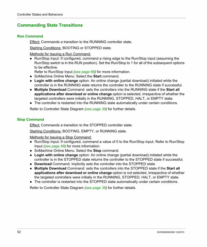
Run Command
Effect: Commands a transition to the RUNNING controller state.
Starting Conditions: BOOTING or STOPPED state.
Methods for Issuing a Run Command: Run/Stop Input: If configured, command a rising edge to the Run/Stop input (assuming the
Run/Stop switch is in the RUN position). Set the Run/Stop to 1 for all of the subsequent options to be effective. Refer to Run/Stop Input (see page 68) for more information.
SoMachine Online Menu: Select the Start command. Login with online change option: An online change (partial download) initiated while the
controller is in the RUNNING state returns the controller to the RUNNING state if successful. Multiple Download Command: sets the controllers into the RUNNING state if the Start all
applications after download or online change option is selected, irrespective of whether the targeted controllers were initially in the RUNNING, STOPPED, HALT, or EMPTY state.
The controller is restarted into the RUNNING state automatically under certain conditions.
Refer to Controller State Diagram (see page 39) for further details.
Stop Command
Effect: Commands a transition to the STOPPED controller state.
Starting Conditions: BOOTING, EMPTY, or RUNNING state.
Methods for Issuing a Stop Command: Run/Stop Input: If configured, command a value of 0 to the Run/Stop input. Refer to Run/Stop
Input (see page 68) for more information. SoMachine Online Menu: Select the Stop command. Login with online change option: An online change (partial download) initiated while the
controller is in the STOPPED state returns the controller to the STOPPED state if successful. Download Command: implicitly sets the controller into the STOPPED state. Multiple Download Command: sets the controllers into the STOPPED state if the Start all
applications after download or online change option is not selected, irrespective of whether the targeted controllers were initially in the RUNNING, STOPPED, HALT, or EMPTY state.
The controller is restarted into the STOPPED state automatically under certain conditions.
Refer to Controller State Diagram (see page 39) for further details.
52 EIO0000000390 12/2015
Controller States and Behaviors
Reset Warm
Effect: Resets all variables, except for the remanent variables, to their default values. Places the controller into the STOPPED state.
Starting Conditions: RUNNING, STOPPED, or HALT states.
Methods for Issuing a Reset Warm Command: SoMachine Online Menu: Select the Reset warm command. By an internal call by the application using the PLC_W. q_wPLCControl and PLC_W. q_uiOpen-
PLCControl system variables of the ATV IMC PLCSystem library (see Altivar ATV IMC Drive Controller, System Functions and Variables, ATV-IMC PLCSystem Library Guide).
Effects of the Reset Warm Command:1. The application stops.2. Forcing is erased.3. Diagnostic indications for errors are reset.4. The values of the retain variables are maintained.5. The values of the retain-persistent variables are maintained.6. All non-located and non-remanent variables are reset to their initialization values.7. The values of the %MW registers are maintained.8. All fieldbus communications are stopped and then restarted after the reset is complete.9. All I/O are briefly reset to their initialization values and then to their user-configured default
values.
For details on variables, refer to Remanent Variables (see page 59).
EIO0000000390 12/2015 53
Controller States and Behaviors
Reset Cold
Effect: Resets all variables, except for the retain-persistent type of remanent variables, to their initialization values. Places the controller into the STOPPED state.
Starting Conditions: RUNNING, STOPPED, or HALT states.
Methods for Issuing a Reset Cold Command: SoMachine Online Menu: Select the Reset cold command. By an internal call by the application using the PLC_W. q_wPLCControl and PLC_W. q_uiOpen-
PLCControl system variables of the ATV IMC PLCSystem library (see Altivar ATV IMC Drive Controller, System Functions and Variables, ATV-IMC PLCSystem Library Guide).
Effects of the Reset Cold Command:1. The application stops.2. Forcing is erased.3. Diagnostic indications for errors are reset.4. The values of the retain variables are reset to their initialization value.5. The values of the retain-persistent variables are maintained.6. All non-located and non-remanent variables are reset to their initialization values.7. The values of the %MW registers are maintained.8. All fieldbus communications are stopped and then restarted after the reset is complete.9. All I/O are briefly reset to their initialization values and then to their user-configured default
values.
For details on variables, refer to Remanent Variables (see page 59).
Reset Origin
Effect: Resets all variables, including the remanent variables, to their initialization values. Erases all user files on the controller. Places the controller into the EMPTY state.
Starting Conditions: RUNNING, STOPPED, or HALT states.
Methods for Issuing a Reset Origin Command: SoMachine Online Menu: Select the Reset origin command.
Effects of the Reset Origin Command:1. The application stops.2. Forcing is erased.3. All user files (Boot application, data logging) are erased.4. Diagnostic indications for errors are reset.5. The values of the retain variables are reset.6. The values of the retain-persistent variables are reset.7. All non-located and non-remanent variables are reset.8. The values of the first 500 %MW registers are maintained.9. All fieldbus communications are stopped.10.All I/O are reset to their initialization values.
For details on variables, refer to Remanent Variables (see page 59).
54 EIO0000000390 12/2015
Controller States and Behaviors
Reboot
Effect: Commands a reboot of the controller.
Starting Conditions: Any state.
Methods for Issuing the Reboot Command: Power cycle
Effects of the Reboot:1. The state of the controller depends on a number of conditions:
a. The controller state will be RUNNING if:The Reboot was provoked by a power cycle and:- the Starting Mode is set to Start in run, and if the Run/Stop input is not configured, and if the controller was not in HALT state before the power cycle, and if the remanent variables are valid.- the Starting Mode is set to Start in run, and if the Run/Stop input is configured and set to RUN, and if the controller was not in HALT state before the power cycle, and if the remanent variables are valid.- the Starting Mode is set to Start in as previous state, and Controller state was RUNNING before the power cycle, and if the Run/Stop input is set to not configured and the boot application has not changed and the remanent variables are valid.- the Starting Mode is set to Start in as previous state, and Controller state was RUNNING before the power cycle, and if the Run/Stop input is configured and is set to RUN.
b. The controller state will be STOPPED if:The Reboot was provoked by a Power cycle and:- the Starting Mode is set to Start in stop.- the Starting Mode is set to Start in as previous state and the controller state was not RUNNING before the power cycle.- the Starting Mode is set to Start in as previous state and the controller state was RUNNING before the power cycle, and if the Run/Stop input is set to not configured, and if the boot application has changed.- the Starting Mode is set to Start in as previous state and the controller state was RUNNING before the power cycle, and if the Run/Stop input is set to not configured, and if the boot application has not changed, and if the remanent variables are not valid.- the Starting Mode is set to Start in as previous state and the controller state was RUNNING before the power cycle, and if the Run/Stop input is configured and is set to STOP.- the Starting Mode is set to Start in run and if the controller state was HALT before the power cycle.- the Starting Mode is set to Start in run, and if the controller state was not HALT before the power cycle, and if the Run/Stop input is configured and is set to STOP.
c. The controller state will be EMPTY if:- There is no boot application or the boot application is invalid, or- The reboot was provoked by specific System Errors.
d. The controller state will be INVALID_OS if there is no valid firmware.
2. Forcing is maintained if the boot application is loaded successfully. If not, forcing is erased.3. Diagnostic indications for errors are reset.4. The values of the retain variables are restored if saved context is valid.
EIO0000000390 12/2015 55
Controller States and Behaviors
5. The values of the retain-persistent variables are restored if saved context is valid.6. All non-located and non-remanent variables are reset to their initialization values.7. The values of the %MW registers are reset to 0.8. All fieldbus communications are stopped and restarted after the boot application is loaded
successfully.9. All I/O are reset to their initialization values and then to their user-configured default values if
the controller assumes a STOPPED state after the reboot.
For details on variables, refer to Remanent Variables (see page 59).
NOTE: The Check context test concludes that the context is valid when the application and the remanent variables are the same as defined in the Boot application.
NOTE: If you provide power to the Run/Stop input from the same source as the controller, the loss of power to this input will be detected immediately, and the controller will behave as if a STOP command was received. Therefore, if you provide power to the controller and the Run/Stop input from the same source, your controller will normally reboot into the STOPPED state after a power interruption when Starting Mode is set to Start in as previous state.
NOTE: If you make an online change to your application program while your controller is in the RUNNING or STOPPED state but do not manually update your Boot application, the controller will detect a difference in context at the next reboot, the remanent variables will be reset as per a Reset cold command, and the controller will enter the STOPPED state.
56 EIO0000000390 12/2015
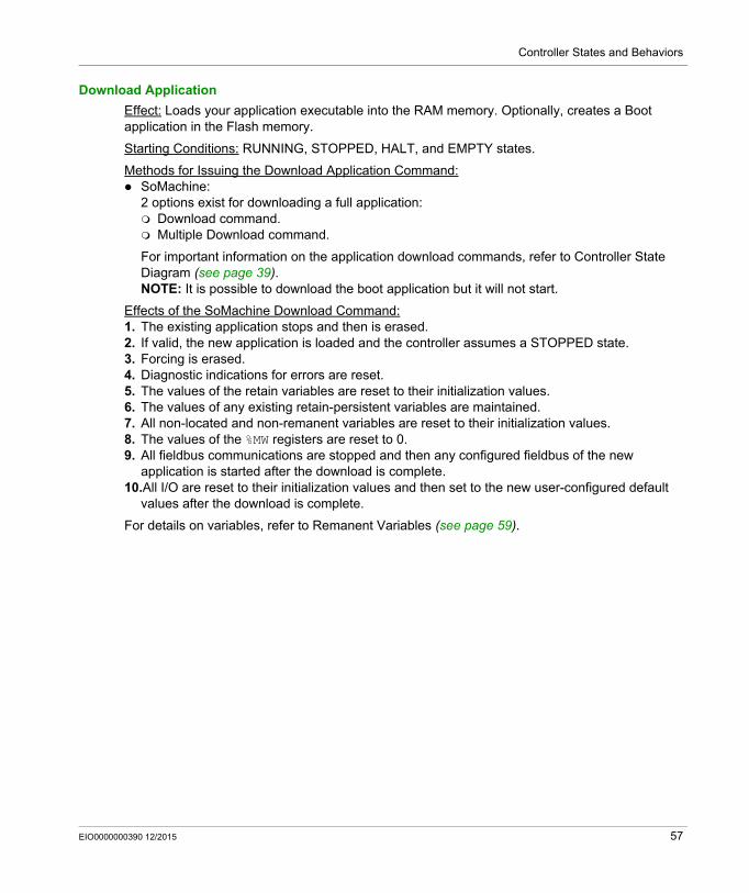
Controller States and Behaviors
Download Application
Effect: Loads your application executable into the RAM memory. Optionally, creates a Boot application in the Flash memory.
Starting Conditions: RUNNING, STOPPED, HALT, and EMPTY states.
Methods for Issuing the Download Application Command: SoMachine:
2 options exist for downloading a full application: Download command. Multiple Download command.
For important information on the application download commands, refer to Controller State Diagram (see page 39).NOTE: It is possible to download the boot application but it will not start.
Effects of the SoMachine Download Command:1. The existing application stops and then is erased.2. If valid, the new application is loaded and the controller assumes a STOPPED state.3. Forcing is erased.4. Diagnostic indications for errors are reset.5. The values of the retain variables are reset to their initialization values.6. The values of any existing retain-persistent variables are maintained.7. All non-located and non-remanent variables are reset to their initialization values.8. The values of the %MW registers are reset to 0.9. All fieldbus communications are stopped and then any configured fieldbus of the new
application is started after the download is complete.10.All I/O are reset to their initialization values and then set to the new user-configured default
values after the download is complete.
For details on variables, refer to Remanent Variables (see page 59).
EIO0000000390 12/2015 57
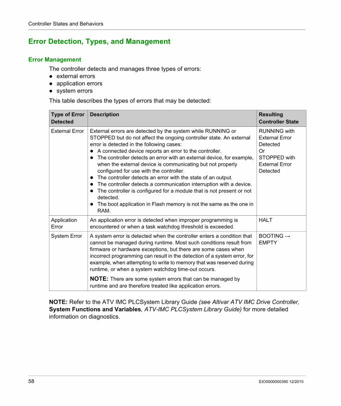
Controller States and Behaviors
Error Detection, Types, and Management
Error Management
The controller detects and manages three types of errors: external errors application errors system errors
This table describes the types of errors that may be detected:
NOTE: Refer to the ATV IMC PLCSystem Library Guide (see Altivar ATV IMC Drive Controller, System Functions and Variables, ATV-IMC PLCSystem Library Guide) for more detailed information on diagnostics.
Type of Error Detected
Description Resulting Controller State
External Error External errors are detected by the system while RUNNING or STOPPED but do not affect the ongoing controller state. An external error is detected in the following cases: A connected device reports an error to the controller. The controller detects an error with an external device, for example,
when the external device is communicating but not properly configured for use with the controller.
The controller detects an error with the state of an output. The controller detects a communication interruption with a device. The controller is configured for a module that is not present or not
detected. The boot application in Flash memory is not the same as the one in
RAM.
RUNNING with External Error DetectedOrSTOPPED with External Error Detected
Application Error
An application error is detected when improper programming is encountered or when a task watchdog threshold is exceeded.
HALT
System Error A system error is detected when the controller enters a condition that cannot be managed during runtime. Most such conditions result from firmware or hardware exceptions, but there are some cases when incorrect programming can result in the detection of a system error, for example, when attempting to write to memory that was reserved during runtime, or when a system watchdog time-out occurs.
NOTE: There are some system errors that can be managed by runtime and are therefore treated like application errors.
BOOTING → EMPTY
58 EIO0000000390 12/2015
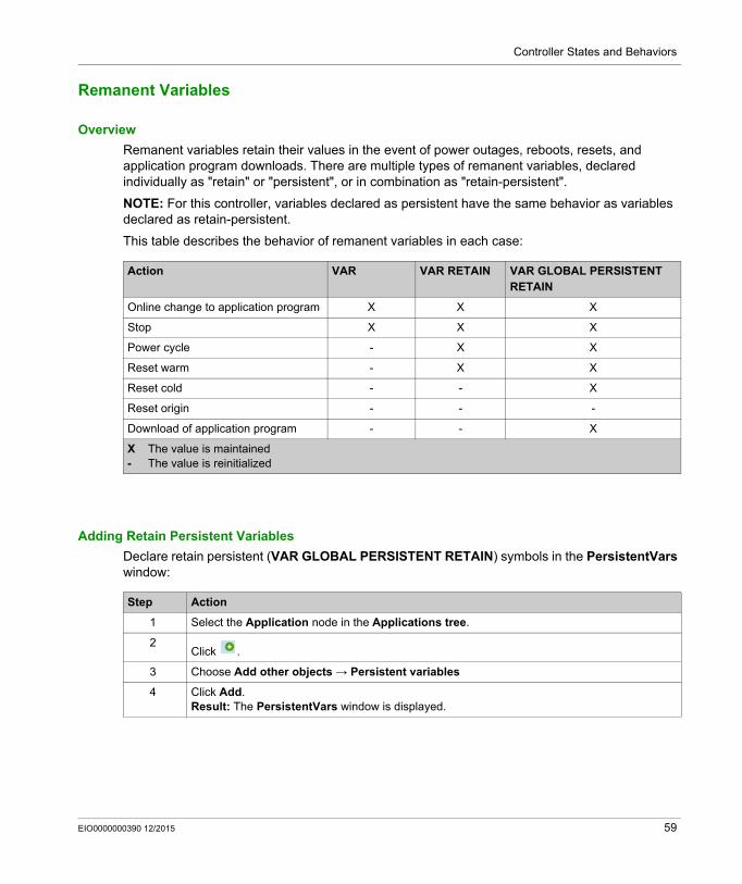
Controller States and Behaviors
Remanent Variables
Overview
Remanent variables retain their values in the event of power outages, reboots, resets, and application program downloads. There are multiple types of remanent variables, declared individually as "retain" or "persistent", or in combination as "retain-persistent".
NOTE: For this controller, variables declared as persistent have the same behavior as variables declared as retain-persistent.
This table describes the behavior of remanent variables in each case:
Adding Retain Persistent Variables
Declare retain persistent (VAR GLOBAL PERSISTENT RETAIN) symbols in the PersistentVars window:
Action VAR VAR RETAIN VAR GLOBAL PERSISTENT RETAIN
Online change to application program X X X
Stop X X X
Power cycle - X X
Reset warm - X X
Reset cold - - X
Reset origin - - -
Download of application program - - X
X The value is maintained- The value is reinitialized
Step Action
1 Select the Application node in the Applications tree.
2Click .
3 Choose Add other objects → Persistent variables
4 Click Add.Result: The PersistentVars window is displayed.
EIO0000000390 12/2015 59

Controller States and Behaviors
60 EIO0000000390 12/2015
Altivar ATV IMC Drive Controller
Controller Device Editor
EIO0000000390 12/2015
Controller Device Editor
Chapter 9Controller Device Editor
Introduction
This chapter describes how to configure the controller.
What Is in This Chapter?
This chapter contains the following topics:
Topic Page
Controller Parameters 62
Controller Selection 64
Services 66
EIO0000000390 12/2015 61
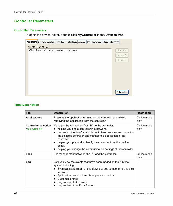
Controller Device Editor
Controller Parameters
Controller Parameters
To open the device editor, double-click MyController in the Devices tree:
Tabs Description
Tab Description Restriction
Applications Presents the application running on the controller and allows removing the application from the controller.
Online mode only
Controller selection (see page 64)
Manages the connection from PC to the controller: helping you find a controller in a network, presenting the list of available controllers, so you can connect to
the selected controller and manage the application in the controller,
helping you physically identify the controller from the device editor,
helping you change the communication settings of the controller.
Online mode only
Files File management between the PC and the controller. Online mode only
Log Lets you view the events that have been logged on the runtime system including: Events at system start or shutdown (loaded components and their
versions) Application download and boot project download Customer entries Log entries of I/O drivers Log entries of the Data Server
–
62 EIO0000000390 12/2015
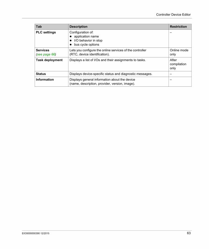
Controller Device Editor
PLC settings Configuration of: application name I/O behavior in stop bus cycle options
–
Services (see page 66)
Lets you configure the online services of the controller (RTC, device identification).
Online mode only
Task deployment Displays a list of I/Os and their assignments to tasks. After compilation only
Status Displays device-specific status and diagnostic messages. –
Information Displays general information about the device (name, description, provider, version, image).
–
Tab Description Restriction
EIO0000000390 12/2015 63
Controller Device Editor
Controller Selection
Introduction
This tab allows you to manage the connection from the PC to the controller: Helping you find a controller in a network. Presenting the list of controllers, so you can connect to the selected controller and manage the
application inside the controller. Helping you physically identify the controller from the device editor. Helping you change the communication settings of the controller.
Process Communication Settings
The Process communication settings window lets you change the Ethernet communication settings. To do so, click Controller selection tab. The list of controllers available in the network appears. Select and right-click the required row and click Process communication settings ... in the context menu.
64 EIO0000000390 12/2015
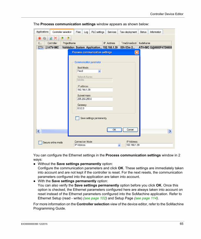
Controller Device Editor
The Process communication settings window appears as shown below:
You can configure the Ethernet settings in the Process communication settings window in 2 ways: Without the Save settings permanently option:
Configure the communication parameters and click OK. These settings are immediately taken into account and are not kept if the controller is reset. For the next resets, the communication parameters configured into the application are taken into account.
With the Save settings permanently option:You can also verify the Save settings permanently option before you click OK. Once this option is checked, the Ethernet parameters configured here are always taken into account on reset instead of the Ethernet parameters configured into the SoMachine application. Refer to Ethernet Setup (read - write) (see page 102) and Setup Page (see page 114).
For more information on the Controller selection view of the device editor, refer to the SoMachine Programming Guide.
EIO0000000390 12/2015 65

Controller Device Editor
Services
Services Tab
The Services tab is divided in 2 parts: RTC Configuration Device Identification
The figure below shows the Services tab:
NOTE: To have controller information, you must be connected to the controller.
Element Description
RTC Configuration
PLC time Displays the date/time read from the controller. This read-only field is initially empty. To read and display the date/time saved on the controller, click the Read button.
Local time Lets you define a date and a time that are sent to the controller by clicking the Write button. A message box informs you on the success of the command. Local time fields are initialized with the current PC settings.
Synchronize with local date/time
Lets you directly send the current PC settings. A message box informs you on the success of the command.
Device Identification Displays the Firmware version and the Boot Version of the selected controller, if connected.
66 EIO0000000390 12/2015
Altivar ATV IMC Drive Controller
Local Input/Output Configuration
EIO0000000390 12/2015
Local Input/Output Configuration
Chapter 10Local Input/Output Configuration
Overview
This chapter shows the local I/O configuration editor and the list of parameters.
What Is in This Chapter?
This chapter contains the following topics:
Topic Page
Local I/O Configuration 68
Addressing 70
EIO0000000390 12/2015 67
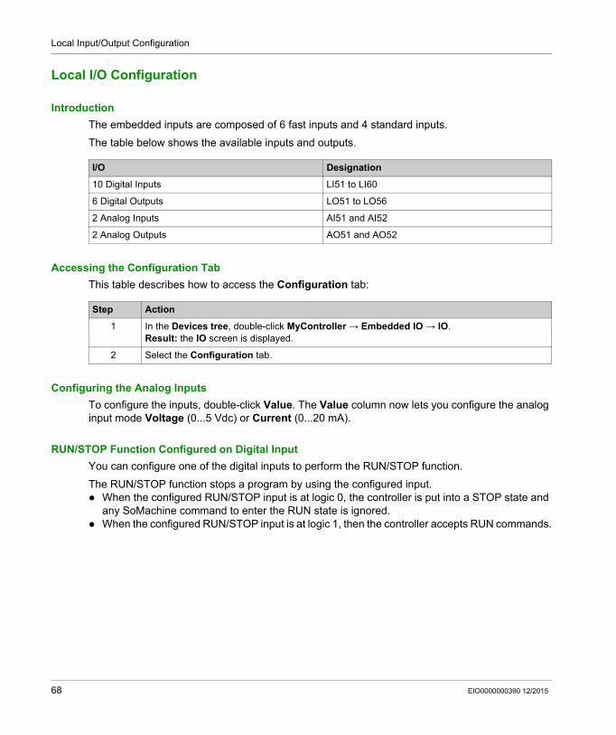
Local Input/Output Configuration
Local I/O Configuration
Introduction
The embedded inputs are composed of 6 fast inputs and 4 standard inputs.
The table below shows the available inputs and outputs.
Accessing the Configuration Tab
This table describes how to access the Configuration tab:
Configuring the Analog Inputs
To configure the inputs, double-click Value. The Value column now lets you configure the analog input mode Voltage (0...5 Vdc) or Current (0...20 mA).
RUN/STOP Function Configured on Digital Input
You can configure one of the digital inputs to perform the RUN/STOP function.
The RUN/STOP function stops a program by using the configured input. When the configured RUN/STOP input is at logic 0, the controller is put into a STOP state and
any SoMachine command to enter the RUN state is ignored. When the configured RUN/STOP input is at logic 1, then the controller accepts RUN commands.
I/O Designation
10 Digital Inputs LI51 to LI60
6 Digital Outputs LO51 to LO56
2 Analog Inputs AI51 and AI52
2 Analog Outputs AO51 and AO52
Step Action
1 In the Devices tree, double-click MyController → Embedded IO → IO.Result: the IO screen is displayed.
2 Select the Configuration tab.
68 EIO0000000390 12/2015
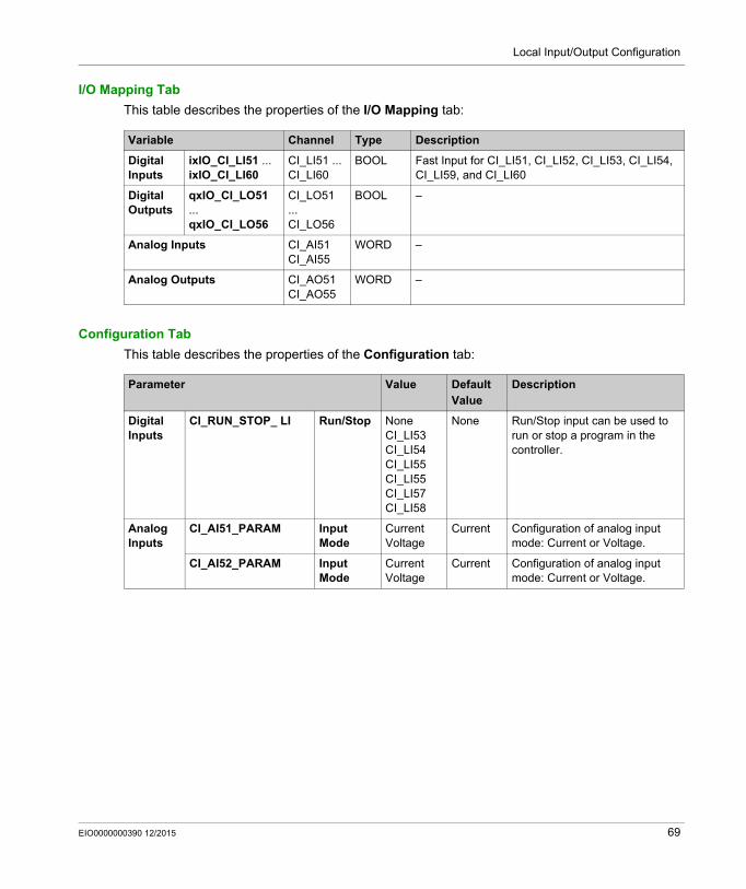
Local Input/Output Configuration
I/O Mapping Tab
This table describes the properties of the I/O Mapping tab:
Configuration Tab
This table describes the properties of the Configuration tab:
Variable Channel Type Description
Digital Inputs
ixIO_CI_LI51 ... ixIO_CI_LI60
CI_LI51 ... CI_LI60
BOOL Fast Input for CI_LI51, CI_LI52, CI_LI53, CI_LI54, CI_LI59, and CI_LI60
Digital Outputs
qxIO_CI_LO51 ... qxIO_CI_LO56
CI_LO51 ... CI_LO56
BOOL –
Analog Inputs CI_AI51CI_AI55
WORD –
Analog Outputs CI_AO51CI_AO55
WORD –
Parameter Value Default Value
Description
Digital Inputs
CI_RUN_STOP_ LI Run/Stop NoneCI_LI53CI_LI54CI_LI55CI_LI55CI_LI57CI_LI58
None Run/Stop input can be used to run or stop a program in the controller.
Analog Inputs
CI_AI51_PARAM Input Mode
Current Voltage
Current Configuration of analog input mode: Current or Voltage.
CI_AI52_PARAM Input Mode
Current Voltage
Current Configuration of analog input mode: Current or Voltage.
EIO0000000390 12/2015 69
Local Input/Output Configuration
Addressing
Addressing Methods
SoMachine allows you to program instructions with 2 different methods of parameter usage: symbolic addresses, also called indirect addresses immediate addresses, also called direct addresses
SoMachine allows you to program instructions using either a direct or indirect method of parameter usage. The direct method is called Immediate Addressing where you use direct address of a parameter, such as %IWx or %QWx for example. The indirect method is called Symbolic Addressing where you first define symbols for these same parameters, and then use the symbols in association with your program instructions.
Both methods are valid and acceptable, but Symbolic Addressing offers distinct advantages, especially if you later make modifications to your configuration. When you configure I/O and other devices for your application, SoMachine automatically allocates and assigns the immediate addresses. Afterward, if you add or delete I/O or other devices from your configuration, SoMachine will account for any changes to the configuration by reallocating and reassigning the immediate addresses. This necessarily will change the assignments from what they had once been from the point of the change(s) in the configuration.
If you have already created all or part of your program using immediate addresses, you will need to account for this change in any program instructions, function blocks, etc., by modifying all the immediate addresses that have been reassigned. However, if you use symbols in place of immediate addresses in your program, this action is unnecessary. Symbols are automatically updated with their new immediate address associations provided that they are attached to the address in the I/O Mapping dialog of the corresponding Device Editor, and not simply an ‘AT’ declaration in the program itself.
NOTE: Systematically use symbols while programming to help avoid extensive program modifications and limit the possibility of programming anomalies once a program configuration has been modified by adding or deleting I/O or other devices.
WARNINGUNINTENDED EQUIPMENT OPERATION
Inspect and modify as necessary any immediate addresses used in the program after modifying the configuration.
Failure to follow these instructions can result in death, serious injury, or equipment damage.
70 EIO0000000390 12/2015
Altivar ATV IMC Drive Controller
Local HSC Configuration
EIO0000000390 12/2015
Local HSC Configuration
Chapter 11Local HSC Configuration
Overview
This chapter shows the local HSC configuration editor and the list of parameters.
For more information, refer to the HSC Library User Manual (see Altivar ATV IMC Drive Controller, High Speed Counting, ATV IMC HSC Library Guide):
What Is in This Chapter?
This chapter contains the following topics:
Topic Page
HSC Types 72
HSC Configuration Screen Description 73
EIO0000000390 12/2015 71
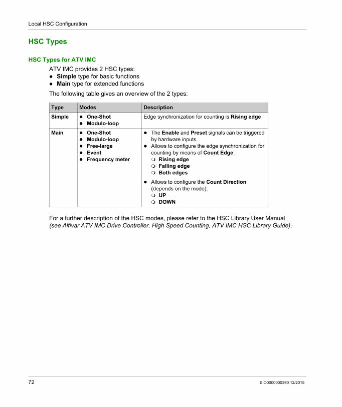
Local HSC Configuration
HSC Types
HSC Types for ATV IMC
ATV IMC provides 2 HSC types: Simple type for basic functions Main type for extended functions
The following table gives an overview of the 2 types:
For a further description of the HSC modes, please refer to the HSC Library User Manual (see Altivar ATV IMC Drive Controller, High Speed Counting, ATV IMC HSC Library Guide).
Type Modes Description
Simple One-Shot Modulo-loop
Edge synchronization for counting is Rising edge
Main One-Shot Modulo-loop Free-large Event Frequency meter
The Enable and Preset signals can be triggered by hardware inputs.
Allows to configure the edge synchronization for counting by means of Count Edge: Rising edge Falling edge Both edges
Allows to configure the Count Direction (depends on the mode): UP DOWN
72 EIO0000000390 12/2015
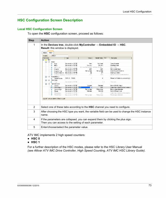
Local HSC Configuration
HSC Configuration Screen Description
Local HSC Configuration Screen
To open the HSC configuration screen, proceed as follows:
ATV IMC implements 2 high speed counters: HSC 0 HSC 1
For a further description of the HSC modes, please refer to the HSC Library User Manual (see Altivar ATV IMC Drive Controller, High Speed Counting, ATV IMC HSC Library Guide).
Step Action
1 In the Devices tree, double-click MyController → Embedded IO → HSC.Result: this window is displayed.
2 Select one of these tabs according to the HSC channel you need to configure.
3 After choosing the HSC type you want, the variable field can be used to change the HSC instance name.
4 If the parameters are collapsed, you can expand them by clicking the plus sign. Then you can access to the setting of each parameter.
5 Enter/choose/select the parameter value.
EIO0000000390 12/2015 73
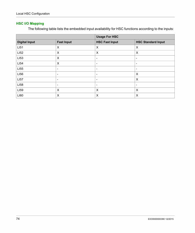
Local HSC Configuration
HSC I/O Mapping
The following table lists the embedded input availability for HSC functions according to the inputs:
Usage For HSC
Digital Input Fast Input HSC Fast Input HSC Standard Input
LI51 X X X
LI52 X X X
LI53 X - -
LI54 X - -
LI55 - - -
LI56 - - X
LI57 - - X
LI58 - - -
LI59 X X X
LI60 X X X
74 EIO0000000390 12/2015

Altivar ATV IMC Drive Controller
Resident Drive Data Configuration
EIO0000000390 12/2015
ATV IMC Resident Drive Data Configuration
Chapter 12ATV IMC Resident Drive Data Configuration
Introduction
This chapter shows you how to configure and use the ATV IMC dedicated data:
What Is in This Chapter?
This chapter contains the following topics:
Topic Page
ATV IMC Resident Drive Configuration and Usage 76
ATV IMC Display Data Configuration and Usage 78
ATV IO Option Board 80
EIO0000000390 12/2015 75
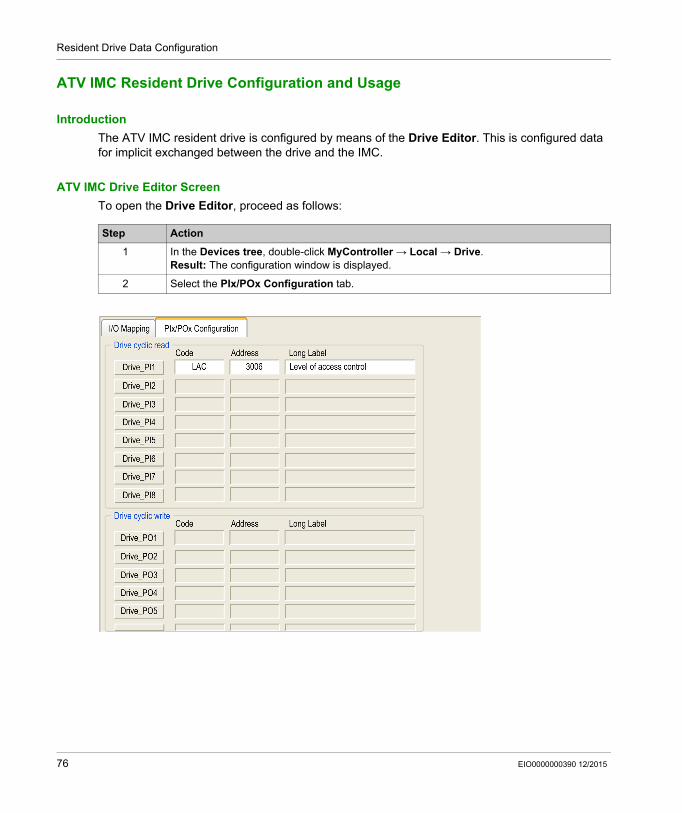
Resident Drive Data Configuration
ATV IMC Resident Drive Configuration and Usage
Introduction
The ATV IMC resident drive is configured by means of the Drive Editor. This is configured data for implicit exchanged between the drive and the IMC.
ATV IMC Drive Editor Screen
To open the Drive Editor, proceed as follows:
Step Action
1 In the Devices tree, double-click MyController → Local → Drive.Result: The configuration window is displayed.
2 Select the PIx/POx Configuration tab.
76 EIO0000000390 12/2015
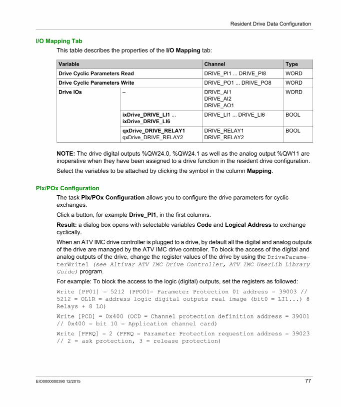
Resident Drive Data Configuration
I/O Mapping Tab
This table describes the properties of the I/O Mapping tab:
NOTE: The drive digital outputs %QW24.0, %QW24.1 as well as the analog output %QW11 are inoperative when they have been assigned to a drive function in the resident drive configuration.
Select the variables to be attached by clicking the symbol in the column Mapping.
PIx/POx Configuration
The task PIx/POx Configuration allows you to configure the drive parameters for cyclic exchanges.
Click a button, for example Drive_PI1, in the first columns.
Result: a dialog box opens with selectable variables Code and Logical Address to exchange cyclically.
When an ATV IMC drive controller is plugged to a drive, by default all the digital and analog outputs of the drive are managed by the ATV IMC drive controller. To block the access of the digital and analog outputs of the drive, change the register values of the drive by using the DriveParame-terWrite1 (see Altivar ATV IMC Drive Controller, ATV IMC UserLib Library Guide) program.
For example: To block the access to the logic (digital) outputs, set the registers as followed:
Write [PP01] = 5212 (PPO01= Parameter Protection 01 address = 39003 // 5212 = OL1R = address logic digital outputs real image (bit0 = LI1...) 8 Relays + 8 LO)
Write [PCD] = 0x400 (OCD = Channel protection definition address = 39001 // 0x400 = bit 10 = Application channel card)
Write [PPRQ] = 2 (PPRQ = Parameter Protection requestion address = 39023 // 2 = ask protection, 3 = release protection)
Variable Channel Type
Drive Cyclic Parameters Read DRIVE_PI1 ... DRIVE_PI8 WORD
Drive Cyclic Parameters Write DRIVE_PO1 ... DRIVE_PO8 WORD
Drive IOs – DRIVE_AI1DRIVE_AI2DRIVE_AO1
WORD
ixDrive_DRIVE_LI1 ... ixDrive_DRIVE_LI6
DRIVE_LI1 ... DRIVE_LI6 BOOL
qxDrive_DRIVE_RELAY1qxDrive_DRIVE_RELAY2
DRIVE_RELAY1DRIVE_RELAY2
BOOL
EIO0000000390 12/2015 77
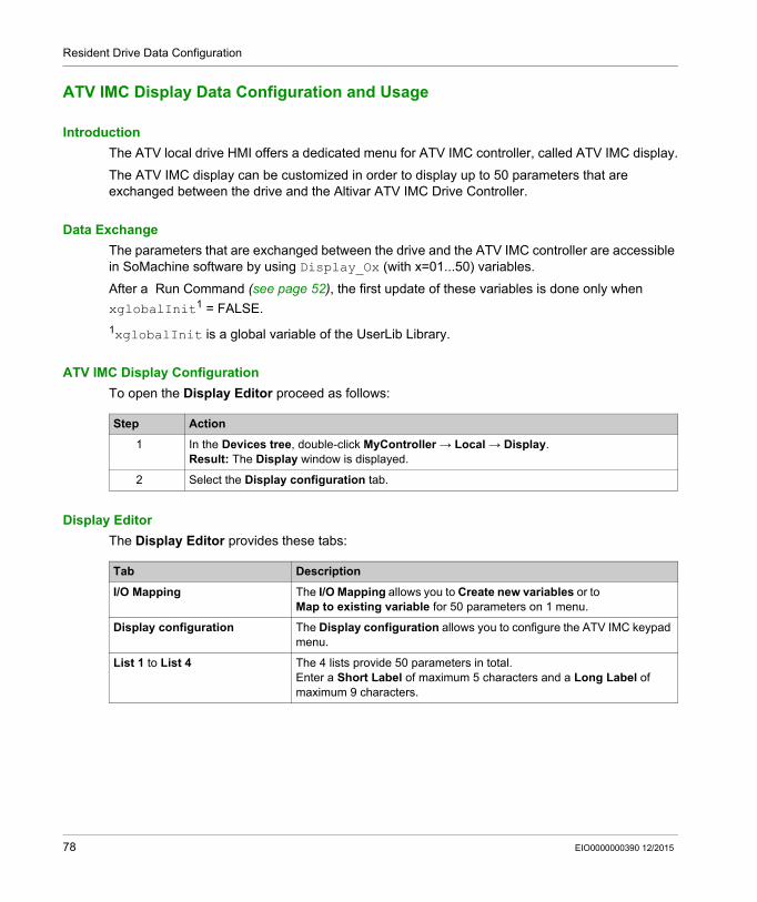
Resident Drive Data Configuration
ATV IMC Display Data Configuration and Usage
Introduction
The ATV local drive HMI offers a dedicated menu for ATV IMC controller, called ATV IMC display.
The ATV IMC display can be customized in order to display up to 50 parameters that are exchanged between the drive and the Altivar ATV IMC Drive Controller.
Data Exchange
The parameters that are exchanged between the drive and the ATV IMC controller are accessible in SoMachine software by using Display_Ox (with x=01...50) variables.
After a Run Command (see page 52), the first update of these variables is done only when
xglobalInit1 = FALSE.
1xglobalInit is a global variable of the UserLib Library.
ATV IMC Display Configuration
To open the Display Editor proceed as follows:
Display Editor
The Display Editor provides these tabs:
Step Action
1 In the Devices tree, double-click MyController → Local → Display.Result: The Display window is displayed.
2 Select the Display configuration tab.
Tab Description
I/O Mapping The I/O Mapping allows you to Create new variables or to Map to existing variable for 50 parameters on 1 menu.
Display configuration The Display configuration allows you to configure the ATV IMC keypad menu.
List 1 to List 4 The 4 lists provide 50 parameters in total.Enter a Short Label of maximum 5 characters and a Long Label of maximum 9 characters.
78 EIO0000000390 12/2015
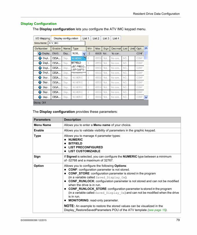
Resident Drive Data Configuration
Display Configuration
The Display configuration lets you configure the ATV IMC keypad menu.
The Display configuration provides these parameters:
Parameters Description
Menu Name Allows you to enter a Menu name of your choice.
Enable Allows you to validate visibility of parameters in the graphic keypad.
Type Allows you to manage 4 parameter types: NUMERIC BITFIELD LIST PRECONFIGURED LIST CUSTOMIZABLE
Sign If Signed is selected, you can configure the NUMERIC type between a minimum of -32768 and a maximum of 32767.
Option Allows you to configure the following Options: CONF: configuration parameter is not stored. CONF_STORE: configuration parameter is stored in the program
(in a variable called Saved_Display_Ox). CONF_RUNLOCK: configuration parameter is not stored and can not be modified
when the drive is in run. CONF_RUNLOCK_STORE: configuration parameter is stored in the program
(in a variable called Saved_Display_Ox) and can not be modified when the drive is in run.
MONITORING: read-only parameter.
NOTE: An example to restore the stored values can be visualized in the Display_RestoreSavedParameters POU of the ATV template (see page 15).
EIO0000000390 12/2015 79
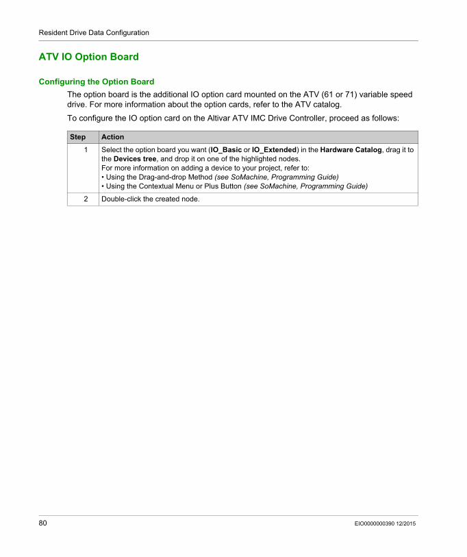
Resident Drive Data Configuration
ATV IO Option Board
Configuring the Option Board
The option board is the additional IO option card mounted on the ATV (61 or 71) variable speed drive. For more information about the option cards, refer to the ATV catalog.
To configure the IO option card on the Altivar ATV IMC Drive Controller, proceed as follows:
Step Action
1 Select the option board you want (IO_Basic or IO_Extended) in the Hardware Catalog, drag it to the Devices tree, and drop it on one of the highlighted nodes.For more information on adding a device to your project, refer to:• Using the Drag-and-drop Method (see SoMachine, Programming Guide)• Using the Contextual Menu or Plus Button (see SoMachine, Programming Guide)
2 Double-click the created node.
80 EIO0000000390 12/2015
\Altivar ATV IMC Drive Controller
Ethernet Configuration
EIO0000000390 12/2015
Ethernet Configuration
Chapter 13Ethernet Configuration
Introduction
This chapter describes how to configure the Ethernet network interface of the ATV IMC.
What Is in This Chapter?
This chapter contains the following topics:
Topic Page
Ethernet Services 82
IP Address Configuration 84
Modbus TCP Slave Device 89
Modbus TCP Server 92
System Variables Description 94
EIO0000000390 12/2015 81
Ethernet Configuration
Ethernet Services
Ethernet Services
The controller supports the following services: FTP Server, Web Server, Modbus TCP Server (slave), SoMachine Manager.
Ethernet Protocol
The controller supports the following protocols: Bootp (Served Configuration Protocol) DHCP (Dynamic Host Configuration Protocol) HTTP (Hyper Text Transfer Protocol) FTP (File Transfer Protocol) IP (Internet Protocol), UDP (User Datagram Protocol), TCP (Transmission Control Protocol), ARP (Address Resolution Protocol), ICMP (Internet Control Messaging Protocol).
TCP Server Connection
This table shows the maximum number of TCP server connection:
Each server based on TCP manages its own pool of 6 simultaneous HTTP connections.
When a client tries to open a connection that exceeds the poll size, the controller closes the oldest.
If all connections are busy (exchange in progress) when a client tries to open a new one the new connection is denied.
All server connections stay open as long as the controller stays in operational state.
Connection Type Maximum Number of Server Connection
Modbus Server 8
Modbus Device 2
FTP Server 4
Web Server 6
82 EIO0000000390 12/2015
Ethernet Configuration
Adding an Ethernet Manager
The controller supports the Modbus TCP Slave Device Ethernet manager.
To add an Ethernet manager, proceed as follows:
Step Action
1 Select the Field Devices tab in the Software Catalog and click Modbus.
2 Select ModbusTCP Slave Device → ModbusTCP Slave Device (Vendor Schneider Electric) in the list, drag-and-drop the item onto Ethernet node of the Devices tree.Result: The module is added to the My Controller → Ethernet area of the Devices tree.Note: The other Ethernet managers are not supported.
EIO0000000390 12/2015 83
Ethernet Configuration
IP Address Configuration
Introduction
There are different ways to assign the IP address of the controller: address assignment by DHCP server address assignment by BOOTP server fixed IP address
The IP address can be changed dynamically: via the Controller Selection tab in SoMachine.
NOTE: If the attempted addressing method is unsuccessful, the controller will start using a default IP address (see page 87) derived from the MAC address.
NOTE: After you download a project with a new IP address, a power cycle is required to take the new IP address into account.
Carefully manage the IP addresses because each device on the network requires a unique address. Having multiple devices with the same IP address can cause unintended operation of your network and associated equipment.
NOTE: Verify that your system administrator maintains a record of all assigned IP addresses on the network and subnetwork, and inform the system administrator of all configuration changes performed.
WARNINGUNINTENDED EQUIPMENT OPERATION
Verify that there is only one master controller configured on the network or remote link. Verify that all devices have unique addresses. Obtain your IP address from your system administrator. Confirm that the IP address of the device is unique before placing the system into service. Do not assign the same IP address to any other equipment on the network. Update the IP address after cloning any application that includes Ethernet communications to
a unique address.
Failure to follow these instructions can result in death, serious injury, or equipment damage.
84 EIO0000000390 12/2015
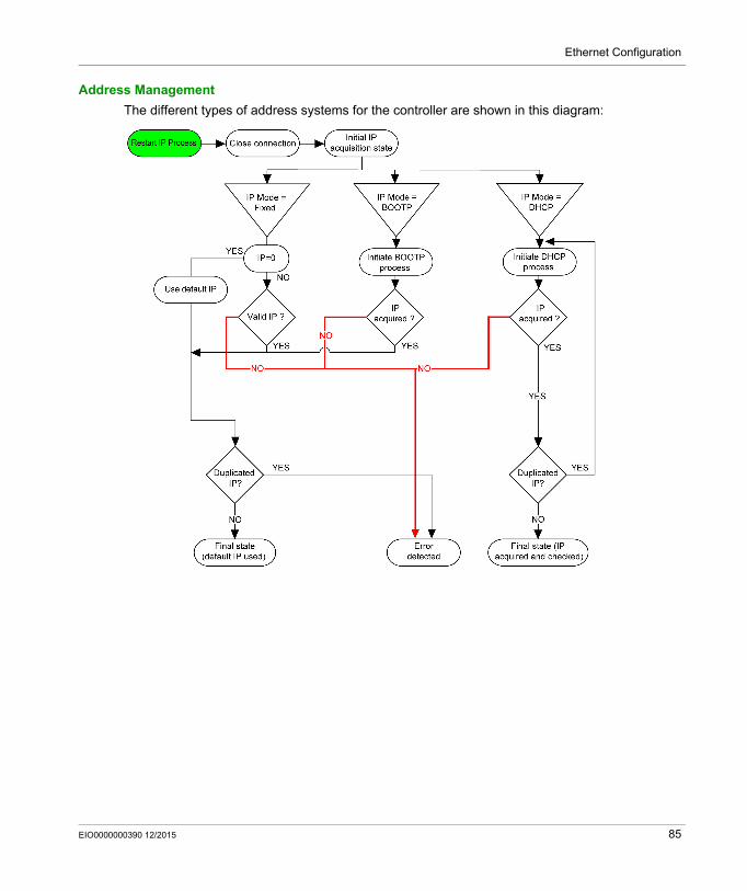
Ethernet Configuration
Address Management
The different types of address systems for the controller are shown in this diagram:
EIO0000000390 12/2015 85
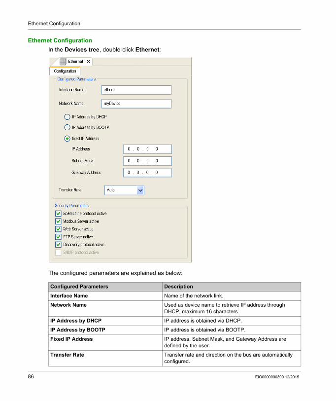
Ethernet Configuration
Ethernet Configuration
In the Devices tree, double-click Ethernet:
The configured parameters are explained as below:
Configured Parameters Description
Interface Name Name of the network link.
Network Name Used as device name to retrieve IP address through DHCP, maximum 16 characters.
IP Address by DHCP IP address is obtained via DHCP.
IP Address by BOOTP IP address is obtained via BOOTP.
Fixed IP Address IP address, Subnet Mask, and Gateway Address are defined by the user.
Transfer Rate Transfer rate and direction on the bus are automatically configured.
86 EIO0000000390 12/2015

Ethernet Configuration
NOTE: The configured parameters are applied only if the option Parameters Updated by Application is enabled. Refer to Ethernet Setup (read - write) (see page 102) and Setup Page (see page 114).
Default IP Address
The IP address by default is 10.10.x.x.
The last 2 fields in the default IP address are composed of the decimal equivalent of the last 2 hexadecimal bytes of the MAC address of the port.
The MAC address of the port can be retrieved on the label placed on the front side of the controller.
The default subnet mask is Default Class A Subnet Mask of 255.0.0.0.
NOTE: A MAC address is always written in hexadecimal format and an IP address in decimal format. Convert the MAC address to decimal format.
Example: If the MAC address is 00.80.F4.01.80.F2, the default IP address is 10.10.128.242.
NOTE: To take into account the new IP address after the download of a project, reboot the controller by doing a power cycle.
Address Classes
The IP address is linked: to a device (the host) to the network to which the device is connected
An IP address is always coded using 4 bytes.
The distribution of these bytes between the network address and the device address may vary.This distribution is defined by the address classes.
The different IP address classes are defined in this table:
Address Class Byte1 Byte 2 Byte 3 Byte 4
Class A 0 Network ID Host ID
Class B 1 0 Network ID Host ID
Class C 1 1 0 Network ID Host ID
Class D 1 1 1 0 Multicast Address
Class E 1 1 1 1 0 Address reserved for subsequent use
EIO0000000390 12/2015 87
Ethernet Configuration
Subnet Mask
The subnet mask is used to address several physical networks with a single network address. The mask is used to separate the subnetwork and the device address in the host ID.
The subnet address is obtained by retaining the bits of the IP address that correspond to the positions of the mask containing 1, and replacing the others with 0.
Conversely, the subnet address of the host device is obtained by retaining the bits of the IP address that correspond to the positions of the mask containing 0, and replacing the others with 1.
Example of a subnet address:
NOTE: The device does not communicate on its subnetwork when there is no gateway.
Gateway Address
The gateway allows a message to be routed to a device that is not on the current network.
If there is no gateway, the gateway address is 0.0.0.0.
Security Parameters
IP address 192 (11000000) 1 (00000001) 17 (00010001) 11 (00001011)
Subnet mask 255 (11111111) 255 (11111111) 240 (11110000) 0 (00000000)
Subnet address 192 (11000000) 1 (00000001) 16 (00010000) 0 (00000000)
Security Parameters Description
SoMachine protocol active
It allows you to deactivate the SoMachine protocol on Ethernet interfaces. When deactivated, every SoMachine request from every device will be rejected, including those from the UDP or TCP connection. Therefore, no connection is possible on Ethernet from a PC with SoMachine, from an HMI target that wants to exchange variables with this controller, from an OPC server, or from Controller Assistant.
Modbus Server active It allows you to deactivate the Modbus Server of the Logic Controller. Therefore, every Modbus request to the Logic Controller will be ignored.
Web Server active It allows you to deactivate the Web Server of the Logic Controller. Therefore, every HTTP request to the Logic Controller will be ignored.
FTP Server active It allows you to deactivate the FTP Server of the Logic Controller. Therefore, every FTP request will be ignored.
Discovery protocol active
It allows you to deactivate Discovery protocol. Therefore, every Discovery request will be ignored.
SNMP protocol active Not available.
88 EIO0000000390 12/2015
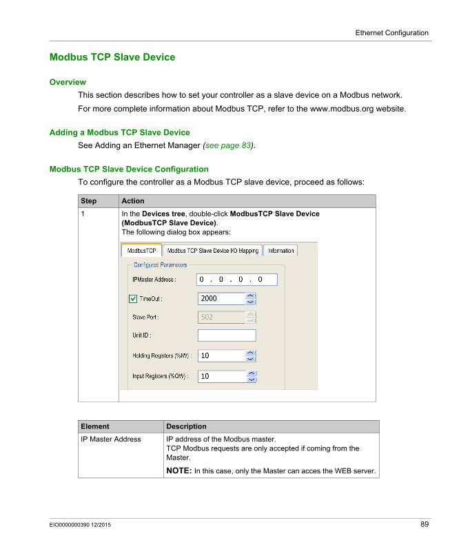
Ethernet Configuration
Modbus TCP Slave Device
Overview
This section describes how to set your controller as a slave device on a Modbus network.
For more complete information about Modbus TCP, refer to the www.modbus.org website.
Adding a Modbus TCP Slave Device
See Adding an Ethernet Manager (see page 83).
Modbus TCP Slave Device Configuration
To configure the controller as a Modbus TCP slave device, proceed as follows:
Step Action
1 In the Devices tree, double-click ModbusTCP Slave Device (ModbusTCP Slave Device). The following dialog box appears:
Element Description
IP Master Address IP address of the Modbus master.TCP Modbus requests are only accepted if coming from the Master.
NOTE: In this case, only the Master can acces the WEB server.
EIO0000000390 12/2015 89
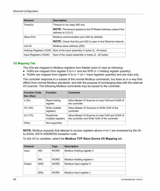
Ethernet Configuration
I/O Mapping Tab
The I/Os are mapped to Modbus registers from Master point of view as following: %IWs are mapped from register 0 to n-1 and are R/W (n = Holding register quantity) %QWs are mapped from register 0 to m -1 (m = Input registers quantity) and are read only.
The controller responds to a subset of the normal Modbus commands, but does so in a way that differs from normal Modbus standards, and with the purpose of exchanging data with the external I/O scanner. The following Modbus commands may be issued to the controller:
NOTE: Modbus requests that attempt to access registers above n+m-1 are answered by the 02 - ILLEGAL DATA ADDRESS exception code.
To link I/O to variables, select the Modbus TCP Slave Device I/O Mapping tab:
TimeOut Timeout in ms (step 500 ms)
NOTE: The timeout applies to the IP Master Address unless if the address is 0.0.0.0.
Slave Port Modbus communication port (502 by default)
NOTE: Check that the port 502 is open in the Ethernet network.
Unit ID Modbus slave address (255)
Holding Registers (%IW) Size of the input assembly in bytes (2...40 bytes)
Input Registers (%QW) Size of the output assembly in bytes (2...40 bytes)
Element Description
Function Code Dec (Hex)
Function Comment
3 (3h) Read holding register
Allow Master IO Scanner to read %IW and %QW of the controller
16 (10h) Write multiple registers
Allow Master IO Scanner to Write %IW of the controller
23 (17h) Read/write multiple registers
Allow Master IO Scanner to read %IW and %QW of the controller and Write %IW of the controller
Other Not supported
Channel Type Description
Input IW0 WORD Modbus Holding register 0
... ... ...
IWx WORD Modbus Holding register x
Output QW0 WORD Modbus Input register 0
... ... ...
QWy WORD Modbus Input register y
90 EIO0000000390 12/2015

Ethernet Configuration
The number of word depends on the Holding Registers (%IW) and Input Registers (%QW) parameters of the ModbusTCP tab.
NOTE: Output means OUTPUT for the Modbus Master (= %IW for the controller).Input means INPUT for the Modbus Master (= %QW for the controller).
EIO0000000390 12/2015 91
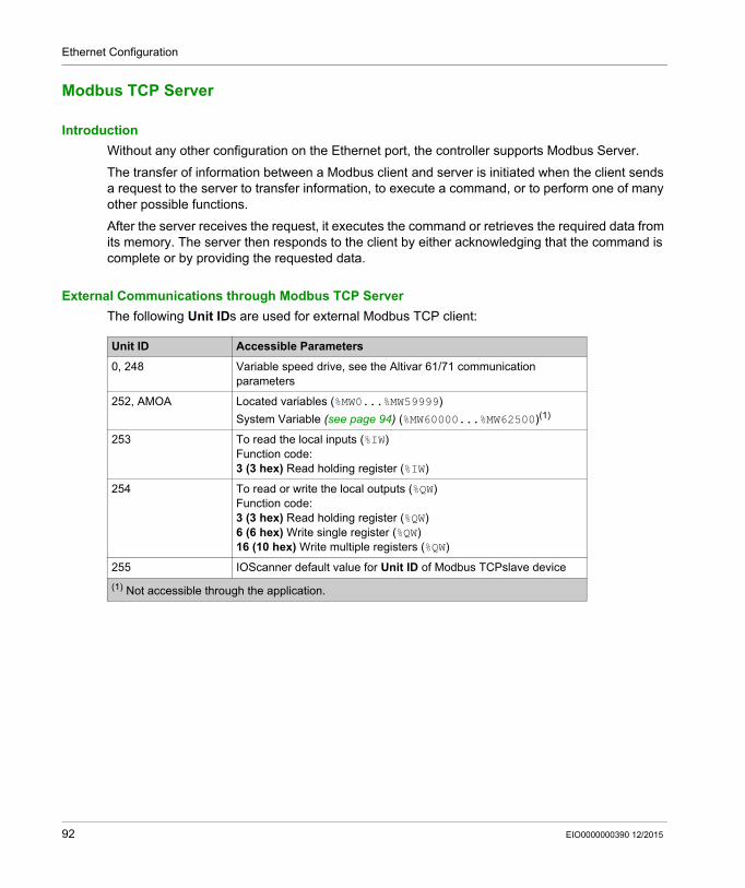
Ethernet Configuration
Modbus TCP Server
Introduction
Without any other configuration on the Ethernet port, the controller supports Modbus Server.
The transfer of information between a Modbus client and server is initiated when the client sends a request to the server to transfer information, to execute a command, or to perform one of many other possible functions.
After the server receives the request, it executes the command or retrieves the required data from its memory. The server then responds to the client by either acknowledging that the command is complete or by providing the requested data.
External Communications through Modbus TCP Server
The following Unit IDs are used for external Modbus TCP client:
Unit ID Accessible Parameters
0, 248 Variable speed drive, see the Altivar 61/71 communication parameters
252, AMOA Located variables (%MW0...%MW59999)
System Variable (see page 94) (%MW60000...%MW62500)(1)
253 To read the local inputs (%IW)Function code:3 (3 hex) Read holding register (%IW)
254 To read or write the local outputs (%QW)Function code:3 (3 hex) Read holding register (%QW)6 (6 hex) Write single register (%QW)16 (10 hex) Write multiple registers (%QW)
255 IOScanner default value for Unit ID of Modbus TCPslave device
(1) Not accessible through the application.
92 EIO0000000390 12/2015
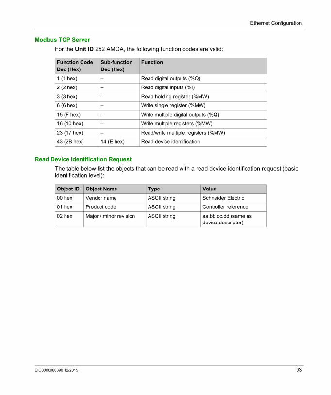
Ethernet Configuration
Modbus TCP Server
For the Unit ID 252 AMOA, the following function codes are valid:
Read Device Identification Request
The table below list the objects that can be read with a read device identification request (basic identification level):
Function CodeDec (Hex)
Sub-functionDec (Hex)
Function
1 (1 hex) – Read digital outputs (%Q)
2 (2 hex) – Read digital inputs (%I)
3 (3 hex) – Read holding register (%MW)
6 (6 hex) – Write single register (%MW)
15 (F hex) – Write multiple digital outputs (%Q)
16 (10 hex) – Write multiple registers (%MW)
23 (17 hex) – Read/write multiple registers (%MW)
43 (2B hex) 14 (E hex) Read device identification
Object ID Object Name Type Value
00 hex Vendor name ASCII string Schneider Electric
01 hex Product code ASCII string Controller reference
02 hex Major / minor revision ASCII string aa.bb.cc.dd (same as device descriptor)
EIO0000000390 12/2015 93
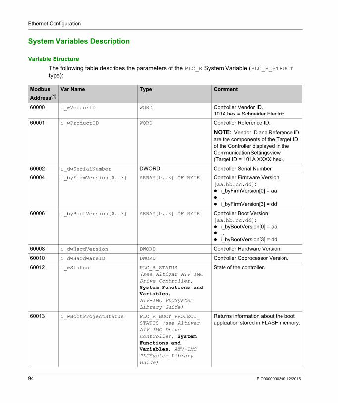
Ethernet Configuration
System Variables Description
Variable Structure
The following table describes the parameters of the PLC_R System Variable (PLC_R_STRUCT type):
Modbus
Address(1)
Var Name Type Comment
60000 i_wVendorID WORD Controller Vendor ID.101A hex = Schneider Electric
60001 i_wProductID WORD Controller Reference ID.
NOTE: Vendor ID and Reference ID are the components of the Target ID of the Controller displayed in the Communication Settings view (Target ID = 101A XXXX hex).
60002 i_dwSerialNumber DWORD Controller Serial Number
60004 i_byFirmVersion[0..3] ARRAY[0..3] OF BYTE Controller Firmware Version [aa.bb.cc.dd]: i_byFirmVersion[0] = aa ... i_byFirmVersion[3] = dd
60006 i_byBootVersion[0..3] ARRAY[0..3] OF BYTE Controller Boot Version [aa.bb.cc.dd]: i_byBootVersion[0] = aa ... i_byBootVersion[3] = dd
60008 i_dwHardVersion DWORD Controller Hardware Version.
60010 i_dwHardwareID DWORD Controller Coprocessor Version.
60012 i_wStatus PLC_R_STATUS (see Altivar ATV IMC Drive Controller, System Functions and Variables, ATV-IMC PLCSystem Library Guide)
State of the controller.
60013 i_wBootProjectStatus PLC_R_BOOT_PROJECT_ STATUS (see Altivar ATV IMC Drive Controller, System Functions and Variables, ATV-IMC PLCSystem Library Guide)
Returns information about the boot application stored in FLASH memory.
94 EIO0000000390 12/2015
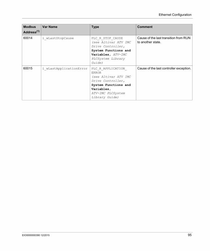
Ethernet Configuration
60014 i_wLastStopCause PLC_R_STOP_CAUSE (see Altivar ATV IMC Drive Controller, System Functions and Variables, ATV-IMC PLCSystem Library Guide)
Cause of the last transition from RUN to another state.
60015 i_wLastApplicationError PLC_R_APPLICATION_ ERROR (see Altivar ATV IMC Drive Controller, System Functions and Variables, ATV-IMC PLCSystem Library Guide)
Cause of the last controller exception.
Modbus
Address(1)
Var Name Type Comment
EIO0000000390 12/2015 95
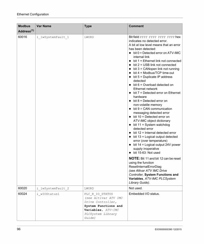
Ethernet Configuration
60016 i_lwSystemFault_1 LWORD Bit field FFFF FFFF FFFF FFFF hex indicates no detected error.A bit at low level means that an error has been detected: bit 0 = Detected error on ATV-IMC
internal link bit 1 = Ethernet link not connected bit 2 = USB link not connected bit 3 = CANopen link not running bit 4 = Modbus/TCP time-out bit 5 = Duplicate IP address
detected bit 6 = Overload detected on
Ethernet network bit 7 = Detected error on Ethernet
hardware bit 8 = Detected error on
non-volatile memory bit 9 = CAN communication
messaging detected error bit 10 = Detected error on
ATV-IMC object dictionary bit 11 = System watchdog
detected error bit 12 = Internal detected error bit 13 = Logical output detected
error (over temperature) bit 14 = Logical output 24V power
supply inoperative bit 15-63: Not used
NOTE: Bit 11 and bit 12 can be reset using the function ResetInternalErrorDiag (see Altivar ATV IMC Drive Controller, System Functions and Variables, ATV-IMC PLCSystem Library Guide).
60020 i_lwSystemFault_2 LWORD Not used.
60024 i_wIOStatus1 PLC_R_IO_STATUS (see Altivar ATV IMC Drive Controller, System Functions and Variables, ATV-IMC PLCSystem Library Guide)
Embedded I/O status.
Modbus
Address(1)
Var Name Type Comment
96 EIO0000000390 12/2015
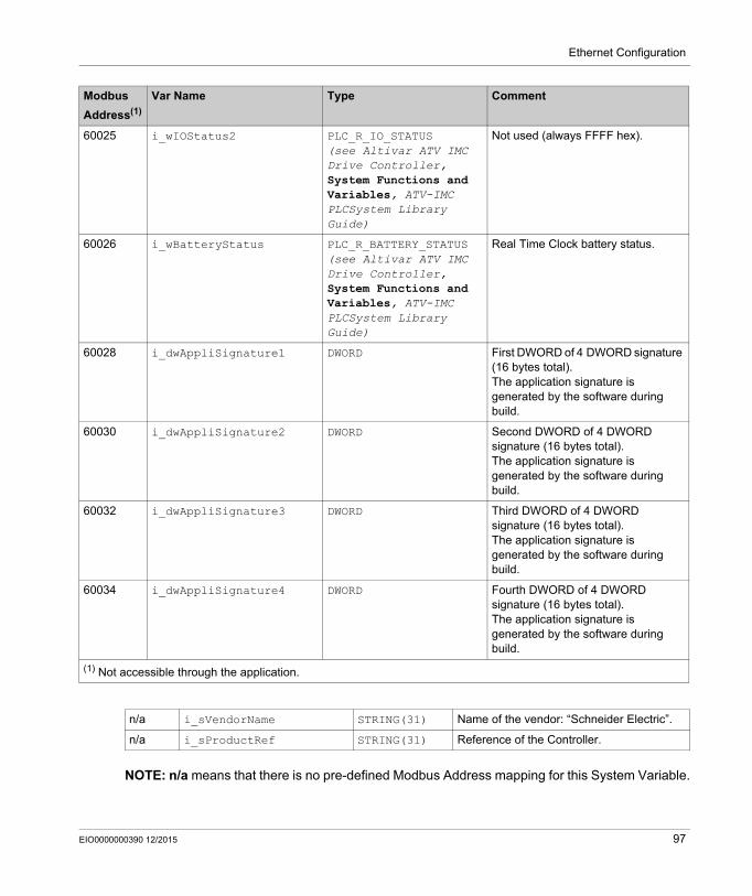
Ethernet Configuration
NOTE: n/a means that there is no pre-defined Modbus Address mapping for this System Variable.
60025 i_wIOStatus2 PLC_R_IO_STATUS (see Altivar ATV IMC Drive Controller, System Functions and Variables, ATV-IMC PLCSystem Library Guide)
Not used (always FFFF hex).
60026 i_wBatteryStatus PLC_R_BATTERY_STATUS (see Altivar ATV IMC Drive Controller, System Functions and Variables, ATV-IMC PLCSystem Library Guide)
Real Time Clock battery status.
60028 i_dwAppliSignature1 DWORD First DWORD of 4 DWORD signature (16 bytes total).The application signature is generated by the software during build.
60030 i_dwAppliSignature2 DWORD Second DWORD of 4 DWORD signature (16 bytes total).The application signature is generated by the software during build.
60032 i_dwAppliSignature3 DWORD Third DWORD of 4 DWORD signature (16 bytes total).The application signature is generated by the software during build.
60034 i_dwAppliSignature4 DWORD Fourth DWORD of 4 DWORD signature (16 bytes total).The application signature is generated by the software during build.
(1) Not accessible through the application.
Modbus
Address(1)
Var Name Type Comment
n/a i_sVendorName STRING(31) Name of the vendor: “Schneider Electric”.
n/a i_sProductRef STRING(31) Reference of the Controller.
EIO0000000390 12/2015 97
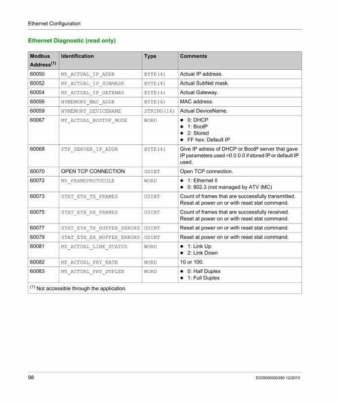
Ethernet Configuration
Ethernet Diagnostic (read only)
Modbus
Address(1)
Identification Type Comments
60050 MY_ACTUAL_IP_ADDR BYTE(4) Actual IP address.
60052 MY_ACTUAL_IP_SUBMASK BYTE(4) Actual SubNet mask.
60054 MY_ACTUAL_IP_GATEWAY BYTE(4) Actual Gateway.
60056 NVMEMORY_MAC_ADDR BYTE(6) MAC address.
60059 NVMEMORY_DEVICENAME STRING(16) Actual DeviceName.
60067 MY_ACTUAL_BOOTUP_MODE WORD 0: DHCP 1: BootP 2: Stored FF hex: Default IP
60068 FTP_SERVER_IP_ADDR BYTE(4) Give IP adress of DHCP or BootP server that gave IP parameters used =0.0.0.0 if stored IP or default IP used.
60070 OPEN TCP CONNECTION UDINT Open TCP connection.
60072 MY_FRAMEPROTOCOLE WORD 1: Ethernet II 0: 802.3 (not managed by ATV IMC)
60073 STAT_ETH_TX_FRAMES UDINT Count of frames that are successfully transmitted.Reset at power on or with reset stat command.
60075 STAT_ETH_RX_FRAMES UDINT Count of frames that are successfully received. Reset at power on or with reset stat command.
60077 STAT_ETH_TX_BUFFER_ERRORS UDINT Reset at power on or with reset stat command.
60079 STAT_ETH_RX_BUFFER_ERRORS UDINT Reset at power on or with reset stat command.
60081 MY_ACTUAL_LINK_STATUS WORD 1: Link Up 2: Link Down
60082 MY_ACTUAL_PHY_RATE WORD 10 or 100.
60083 MY_ACTUAL_PHY_DUPLEX WORD 0: Half Duplex 1: Full Duplex
(1) Not accessible through the application.
98 EIO0000000390 12/2015

Ethernet Configuration
Specific Informations (read only)
Modbus
Address(1)
Identification Type Comments
60200 NVMEMORY_MODBUS_ TIMEOUT
WORD Modbus/TCP timeout in ms.
60201 NVMEMORY_IOSCAN_ ACTIVATION
WORD 0: IOScanning disabled 1: IOScanning enabled
60202 NVMEMORY_MODBUS_ MASTER_IP_ADDR
BYTE(4) If IPMaster is assigned, only the IPMaster can write through Modbus/TCP.
60204 MODBUS_TX_FRAMES DWORD Statistic: Number of Modbus frames sent.
60206 MODBUS_RX_FRAMES DWORD Statistic: Number of Modbus frames received.
60208 MODBUS_IOSCAN_TX DWORD Statistic: Number of Modbus IOScanning frames sent.
60210 MODBUS_IOSCAN_RX DWORD Statistic: Number of Modbus IOScanning frames received.
60212 MODBUS_MSG_ERRORS WORD Statistic: Number of Modbus frame detected errors sent.
60213 MODBUS_IOSCAN_ERRORS WORD Statistic: Number of Modbus IOScanning frames detected errors sent.
60214 MODBUS_TRAFFIC WORD Statistic: Number of Modbus frames received and sent the last second.
60215 MODBUS_MAX_TRAFFIC WORD Statistic: Maximum number of Modbus frames received in 1 second.
60216 MODBUS_NB_CONNECT WORD Statistic: Number of Modbus socket opened.
60217 STAT_ETH_TX_DIFF WORD Statistic: Number of deferred emission.
60218 STAT_ETH_LATE_ COLISION
WORD Statistic: Number of late collision.
60219 STAT_ETH_RX_CRC_ ERRORS
WORD Statistic: Number of CRC detected errors.
60220 STAT_ETH_RX_FRAMES_ ERROR
WORD Statistic: Number of reception frame detected errors.
60221 STAT_ETH_COLISIONS WORD Statistic: Total number of collisions.
60222 STAT_ETH_ MULTICOLISION
WORD Statistic: Number of multicollision.
60223 STAT_ETH_OVERRUN WORD Statistic: Number of overrun.
60224 MY_UDP_SOCKET_SRV_ NBR
WORD Statistic: Number of UDP socket server.
60225 DIGITAL INPUTS WORD 1 digit per input.
EIO0000000390 12/2015 99
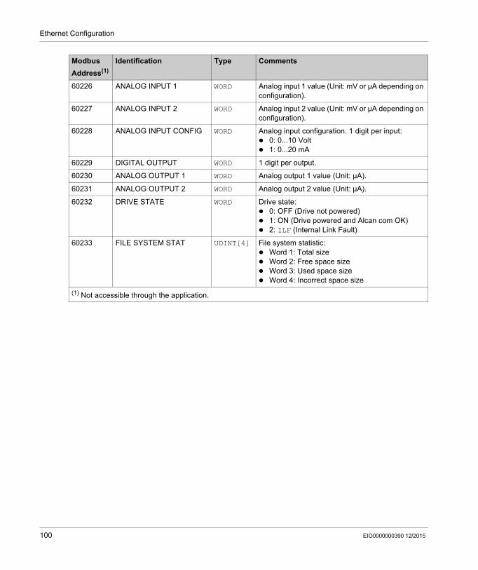
Ethernet Configuration
60226 ANALOG INPUT 1 WORD Analog input 1 value (Unit: mV or µA depending on configuration).
60227 ANALOG INPUT 2 WORD Analog input 2 value (Unit: mV or µA depending on configuration).
60228 ANALOG INPUT CONFIG WORD Analog input configuration. 1 digit per input: 0: 0...10 Volt 1: 0...20 mA
60229 DIGITAL OUTPUT WORD 1 digit per output.
60230 ANALOG OUTPUT 1 WORD Analog output 1 value (Unit: µA).
60231 ANALOG OUTPUT 2 WORD Analog output 2 value (Unit: µA).
60232 DRIVE STATE WORD Drive state: 0: OFF (Drive not powered) 1: ON (Drive powered and Alcan com OK) 2: ILF (Internal Link Fault)
60233 FILE SYSTEM STAT UDINT[4] File system statistic: Word 1: Total size Word 2: Free space size Word 3: Used space size Word 4: Incorrect space size
(1) Not accessible through the application.
Modbus
Address(1)
Identification Type Comments
100 EIO0000000390 12/2015
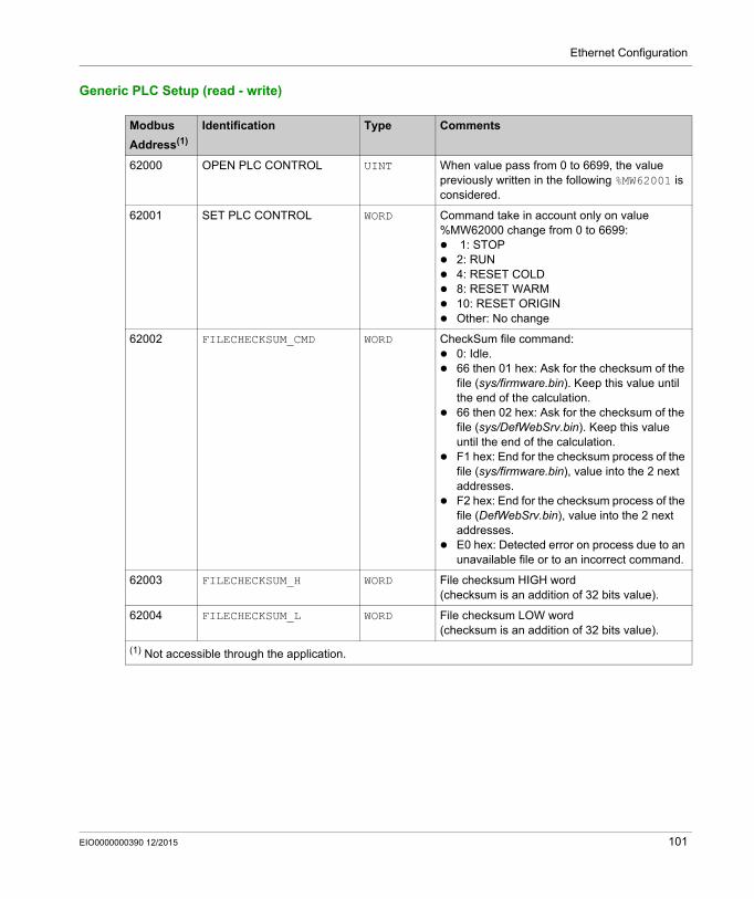
Ethernet Configuration
Generic PLC Setup (read - write)
Modbus
Address(1)
Identification Type Comments
62000 OPEN PLC CONTROL UINT When value pass from 0 to 6699, the value previously written in the following %MW62001 is considered.
62001 SET PLC CONTROL WORD Command take in account only on value %MW62000 change from 0 to 6699: 1: STOP 2: RUN 4: RESET COLD 8: RESET WARM 10: RESET ORIGIN Other: No change
62002 FILECHECKSUM_CMD WORD CheckSum file command: 0: Idle. 66 then 01 hex: Ask for the checksum of the
file (sys/firmware.bin). Keep this value until the end of the calculation.
66 then 02 hex: Ask for the checksum of the file (sys/DefWebSrv.bin). Keep this value until the end of the calculation.
F1 hex: End for the checksum process of the file (sys/firmware.bin), value into the 2 next addresses.
F2 hex: End for the checksum process of the file (DefWebSrv.bin), value into the 2 next addresses.
E0 hex: Detected error on process due to an unavailable file or to an incorrect command.
62003 FILECHECKSUM_H WORD File checksum HIGH word (checksum is an addition of 32 bits value).
62004 FILECHECKSUM_L WORD File checksum LOW word (checksum is an addition of 32 bits value).
(1) Not accessible through the application.
EIO0000000390 12/2015 101
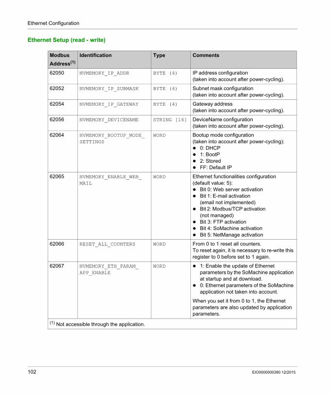
Ethernet Configuration
Ethernet Setup (read - write)
Modbus
Address(1)
Identification Type Comments
62050 NVMEMORY_IP_ADDR BYTE (4) IP address configuration (taken into account after power-cycling).
62052 NVMEMORY_IP_SUBMASK BYTE (4) Subnet mask configuration (taken into account after power-cycling).
62054 NVMEMORY_IP_GATEWAY BYTE (4) Gateway address (taken into account after power-cycling).
62056 NVMEMORY_DEVICENAME STRING [16] DeviceName configuration (taken into account after power-cycling).
62064 NVMEMORY_BOOTUP_MODE_ SETTINGS
WORD Bootup mode configuration (taken into account after power-cycling): 0: DHCP 1: BootP 2: Stored FF: Default IP
62065 NVMEMORY_ENABLE_WEB_ MAIL
WORD Ethernet functionalities configuration (default value: 5): Bit 0: Web server activation Bit 1: E-mail activation
(email not implemented) Bit 2: Modbus/TCP activation
(not managed) Bit 3: FTP activation Bit 4: SoMachine activation Bit 5: NetManage activation
62066 RESET_ALL_COUNTERS WORD From 0 to 1 reset all counters.To reset again, it is necessary to re-write this register to 0 before set to 1 again.
62067 NVMEMORY_ETH_PARAM_ APP_ENABLE
WORD 1: Enable the update of Ethernet parameters by the SoMachine application at startup and at download.
0: Ethernet parameters of the SoMachine application not taken into account.
When you set it from 0 to 1, the Ethernet parameters are also updated by application parameters.
(1) Not accessible through the application.
102 EIO0000000390 12/2015
Altivar ATV IMC Drive Controller
ATV IMC Web Server
EIO0000000390 12/2015
ATV IMC Web Server
Chapter 14ATV IMC Web Server
Introduction
This chapter describes how to access the ATV IMC Web Server.
You can view these pages by installing the module and configuring its IP address.
What Is in This Chapter?
This chapter contains the following topics:
Topic Page
Web Server 104
Monitoring Page 108
Diagnostics Page 113
Setup Page 114
Documentation Page 118
EIO0000000390 12/2015 103
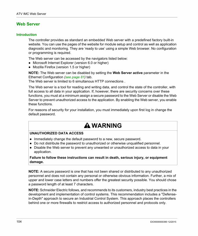
ATV IMC Web Server
Web Server
Introduction
The controller provides as standard an embedded Web server with a predefined factory built-in website. You can use the pages of the website for module setup and control as well as application diagnostic and monitoring. They are ‘ready to use’ using a simple Web browser. No configuration or programming is required.
The Web server can be accessed by the navigators listed below: Microsoft Internet Explorer (version 6.0 or higher) Mozilla Firefox (version 1.5 or higher)
NOTE: The Web server can be disabled by setting the Web Server active parameter in the Ethernet Configuration (see page 81) tab. The Web server is limited to 6 simultanous HTTP connections .
The Web server is a tool for reading and writing data, and control the state of the controller, with full access to all data in your application. If, however, there are security concerns over these functions, you must at a minimum assign a secure password to the Web Server or disable the Web Server to prevent unauthorized access to the application. By enabling the Web server, you enable these functions.
For reasons of security for your installation, you must immediately upon first log in change the default password.
NOTE: A secure password is one that has not been shared or distributed to any unauthorized personnel and does not contain any personal or otherwise obvious information. Further, a mix of upper and lower case letters and numbers offer the greatest security possible. You should chose a password length of at least 7 characters.
NOTE: Schneider Electric follows, and recommends to its customers, industry best practices in the development and implementation of control systems. This recommendation includes a "Defense-in-Depth" approach to secure an Industrial Control System. This approach places the controllers behind one or more firewalls to restrict access to authorized personnel and protocols only.
WARNINGUNAUTHORIZED DATA ACCESS
Immediately change the default password to a new, secure password. Do not distribute the password to unauthorized or otherwise unqualified personnel. Disable the Web server to prevent any unwanted or unauthorized access to data in your
application.
Failure to follow these instructions can result in death, serious injury, or equipment damage.
104 EIO0000000390 12/2015
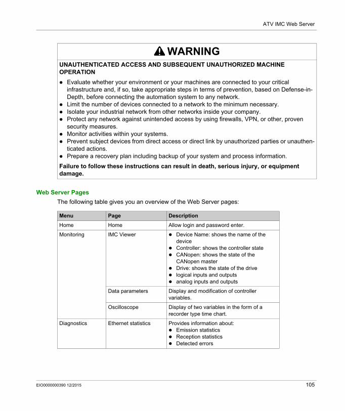
ATV IMC Web Server
Web Server Pages
The following table gives you an overview of the Web Server pages:
WARNINGUNAUTHENTICATED ACCESS AND SUBSEQUENT UNAUTHORIZED MACHINE OPERATION
Evaluate whether your environment or your machines are connected to your critical infrastructure and, if so, take appropriate steps in terms of prevention, based on Defense-in-Depth, before connecting the automation system to any network.
Limit the number of devices connected to a network to the minimum necessary. Isolate your industrial network from other networks inside your company. Protect any network against unintended access by using firewalls, VPN, or other, proven
security measures. Monitor activities within your systems. Prevent subject devices from direct access or direct link by unauthorized parties or unauthen-
ticated actions. Prepare a recovery plan including backup of your system and process information.
Failure to follow these instructions can result in death, serious injury, or equipment damage.
Menu Page Description
Home Home Allow login and password enter.
Monitoring IMC Viewer Device Name: shows the name of the device
Controller: shows the controller state CANopen: shows the state of the
CANopen master Drive: shows the state of the drive logical inputs and outputs analog inputs and outputs
Data parameters Display and modification of controller variables.
Oscilloscope Display of two variables in the form of a recorder type time chart.
Diagnostics Ethernet statistics Provides information about: Emission statistics Reception statistics Detected errors
EIO0000000390 12/2015 105
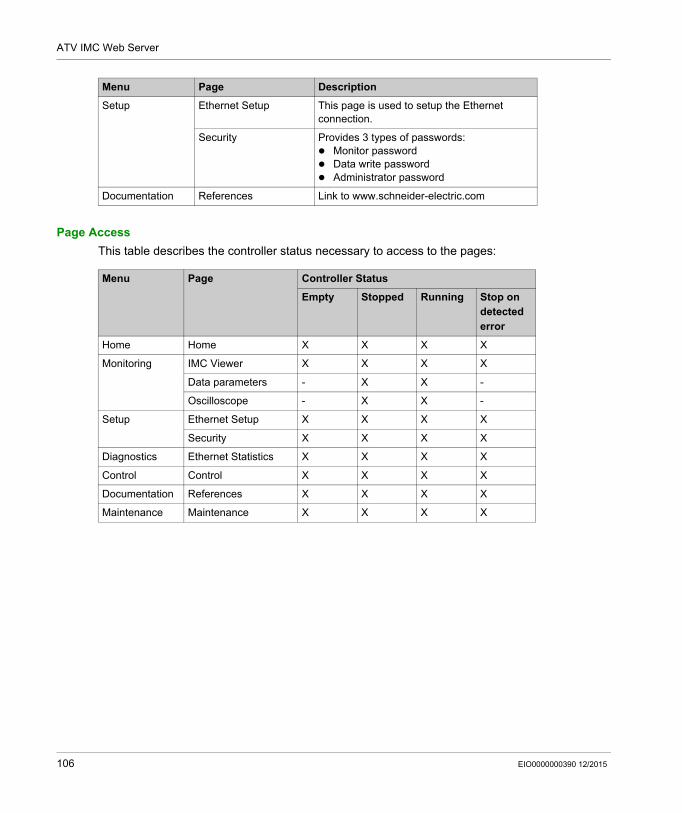
ATV IMC Web Server
Page Access
This table describes the controller status necessary to access to the pages:
Setup Ethernet Setup This page is used to setup the Ethernet connection.
Security Provides 3 types of passwords: Monitor password Data write password Administrator password
Documentation References Link to www.schneider-electric.com
Menu Page Description
Menu Page Controller Status
Empty Stopped Running Stop on detected error
Home Home X X X X
Monitoring IMC Viewer X X X X
Data parameters - X X -
Oscilloscope - X X -
Setup Ethernet Setup X X X X
Security X X X X
Diagnostics Ethernet Statistics X X X X
Control Control X X X X
Documentation References X X X X
Maintenance Maintenance X X X X
106 EIO0000000390 12/2015
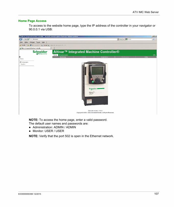
ATV IMC Web Server
Home Page Access
To access to the website home page, type the IP address of the controller in your navigator or 90.0.0.1 via USB:
NOTE: To access the home page, enter a valid password.The default user names and passwords are: Administration: ADMIN / ADMIN Monitor: USER / USER
NOTE: Verify that the port 502 is open in the Ethernet network.
EIO0000000390 12/2015 107
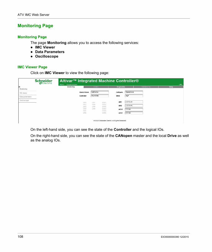
ATV IMC Web Server
Monitoring Page
Monitoring Page
The page Monitoring allows you to access the following services: IMC Viewer Data Parameters Oscilloscope
IMC Viewer Page
Click on IMC Viewer to view the following page:
On the left-hand side, you can see the state of the Controller and the logical IOs.
On the right-hand side, you can see the state of the CANopen master and the local Drive as well as the analog IOs.
108 EIO0000000390 12/2015
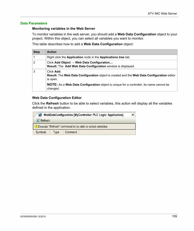
ATV IMC Web Server
Data Parameters
Monitoring variables in the Web Server
To monitor variables in the web server, you should add a Web Data Configuration object to your project. Within this object, you can select all variables you want to monitor.
This table describes how to add a Web Data Configuration object:
Web Data Configuration Editor
Click the Refresh button to be able to select variables, this action will display all the variables defined in the application.
Step Action
1 Right click the Application node in the Applications tree tab.
2 Click Add Object → Web Data Configuration....Result: The Add Web Data Configuration window is displayed.
3 Click Add.Result: The Web Data Configuration object is created and the Web Data Configuration editor is open.
NOTE: As a Web Data Configuration object is unique for a controller, its name cannot be changed.
EIO0000000390 12/2015 109
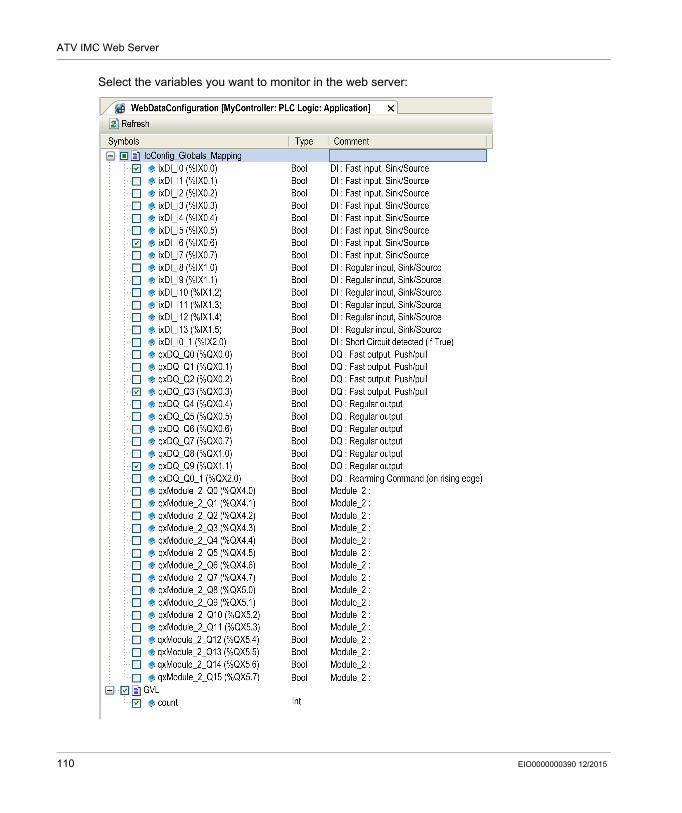
ATV IMC Web Server
Select the variables you want to monitor in the web server:
110 EIO0000000390 12/2015
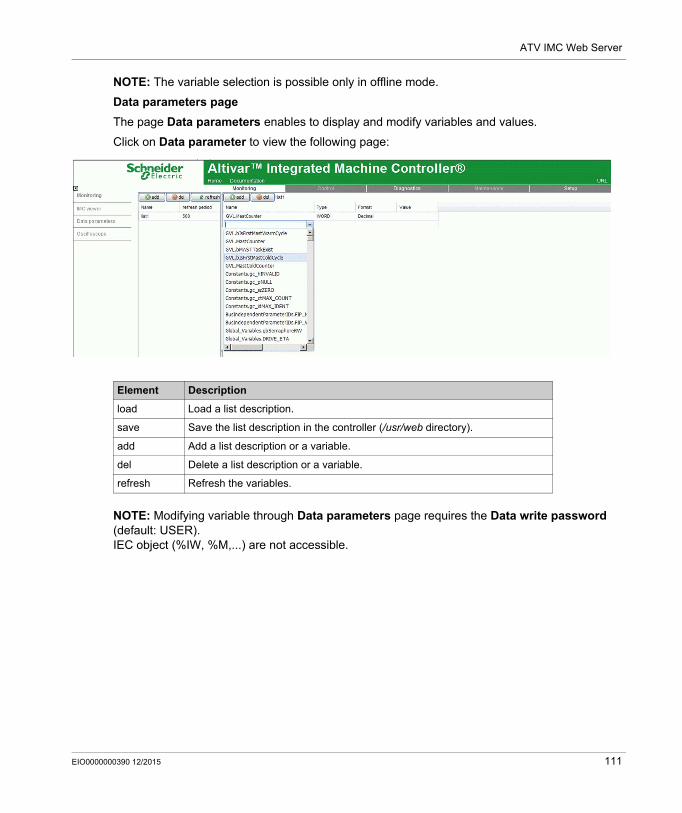
ATV IMC Web Server
NOTE: The variable selection is possible only in offline mode.
Data parameters page
The page Data parameters enables to display and modify variables and values.
Click on Data parameter to view the following page:
NOTE: Modifying variable through Data parameters page requires the Data write password (default: USER).IEC object (%IW, %M,...) are not accessible.
Element Description
load Load a list description.
save Save the list description in the controller (/usr/web directory).
add Add a list description or a variable.
del Delete a list description or a variable.
refresh Refresh the variables.
EIO0000000390 12/2015 111
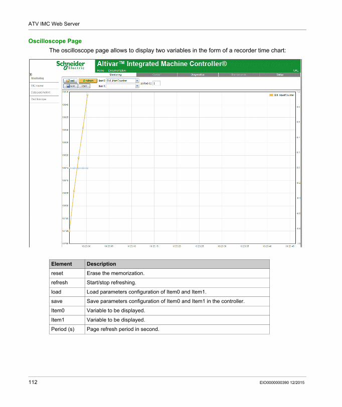
ATV IMC Web Server
Oscilloscope Page
The oscilloscope page allows to display two variables in the form of a recorder time chart:
Element Description
reset Erase the memorization.
refresh Start/stop refreshing.
load Load parameters configuration of Item0 and Item1.
save Save parameters configuration of Item0 and Item1 in the controller.
Item0 Variable to be displayed.
Item1 Variable to be displayed.
Period (s) Page refresh period in second.
112 EIO0000000390 12/2015
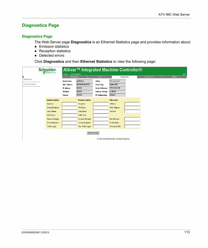
ATV IMC Web Server
Diagnostics Page
Diagnostics Page
The Web Server page Diagnostics is an Ethernet Statistics page and provides information about: Emission statistics Reception statistics Detected errors
Click Diagnostics and then Ethernet Statistics to view the following page:
EIO0000000390 12/2015 113
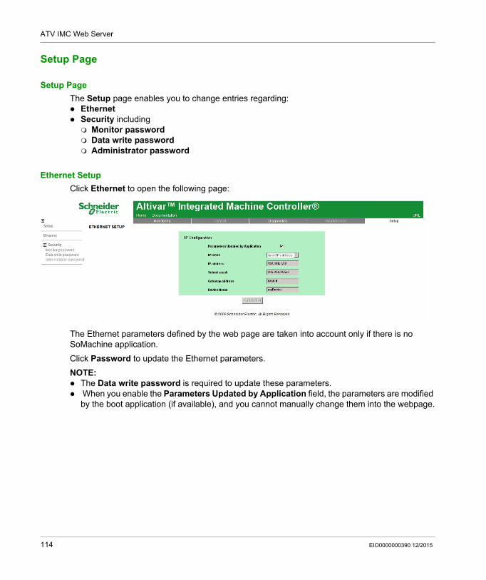
ATV IMC Web Server
Setup Page
Setup Page
The Setup page enables you to change entries regarding: Ethernet Security including Monitor password Data write password Administrator password
Ethernet Setup
Click Ethernet to open the following page:
The Ethernet parameters defined by the web page are taken into account only if there is no SoMachine application.
Click Password to update the Ethernet parameters.
NOTE: The Data write password is required to update these parameters. When you enable the Parameters Updated by Application field, the parameters are modified
by the boot application (if available), and you cannot manually change them into the webpage.
114 EIO0000000390 12/2015
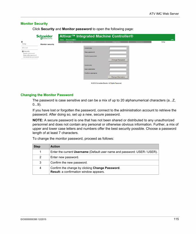
ATV IMC Web Server
Monitor Security
Click Security and Monitor password to open the following page:
Changing the Monitor Password
The password is case sensitive and can be a mix of up to 20 alphanumerical characters (a...Z, 0...9).
If you have lost or forgotten the password, connect to the administration account to retrieve the password. After doing so, set up a new, secure password.
NOTE: A secure password is one that has not been shared or distributed to any unauthorized personnel and does not contain any personal or otherwise obvious information. Further, a mix of upper and lower case letters and numbers offer the best security possible. Choose a password length of at least 7 characters.
To change the monitor password, proceed as follows:
Step Action
1 Enter the current Username (Default user name and password: USER / USER).
2 Enter new password.
3 Confirm the new password.
4 Confirm the change by clicking Change Password.Result: a confirmation window appears.
EIO0000000390 12/2015 115
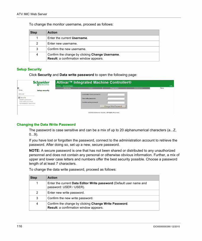
ATV IMC Web Server
To change the monitor username, proceed as follows:
Setup Security
Click Security and Data write password to open the following page:
Changing the Data Write Password
The password is case sensitive and can be a mix of up to 20 alphanumerical characters (a...Z, 0...9).
If you have lost or forgotten the password, connect to the administration account to retrieve the password. After doing so, set up a new, secure password.
NOTE: A secure password is one that has not been shared or distributed to any unauthorized personnel and does not contain any personal or otherwise obvious information. Further, a mix of upper and lower case letters and numbers offer the best security possible. Choose a password length of at least 7 characters.
To change the data write password, proceed as follows:
Step Action
1 Enter the current Username.
2 Enter new username.
3 Confirm the new username.
4 Confirm the change by clicking Change Username.Result: a confirmation window appears.
Step Action
1 Enter the current Data Editor Write password (Default user name and password: USER / USER).
2 Enter new write password.
3 Confirm the new write password.
4 Confirm the change by clicking Change Write Password.Result: a confirmation window appears.
116 EIO0000000390 12/2015
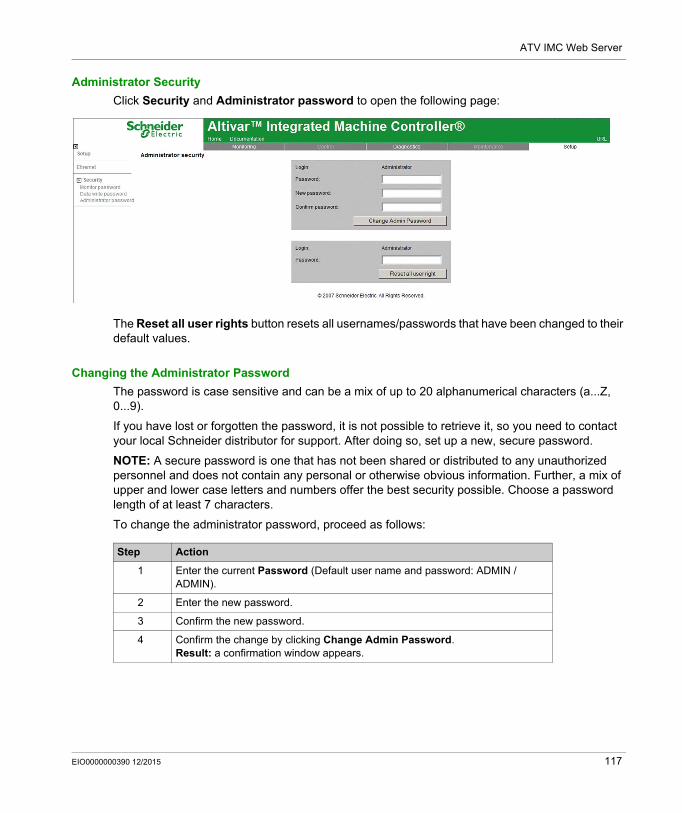
ATV IMC Web Server
Administrator Security
Click Security and Administrator password to open the following page:
The Reset all user rights button resets all usernames/passwords that have been changed to their default values.
Changing the Administrator Password
The password is case sensitive and can be a mix of up to 20 alphanumerical characters (a...Z, 0...9).
If you have lost or forgotten the password, it is not possible to retrieve it, so you need to contact your local Schneider distributor for support. After doing so, set up a new, secure password.
NOTE: A secure password is one that has not been shared or distributed to any unauthorized personnel and does not contain any personal or otherwise obvious information. Further, a mix of upper and lower case letters and numbers offer the best security possible. Choose a password length of at least 7 characters.
To change the administrator password, proceed as follows:
Step Action
1 Enter the current Password (Default user name and password: ADMIN / ADMIN).
2 Enter the new password.
3 Confirm the new password.
4 Confirm the change by clicking Change Admin Password.Result: a confirmation window appears.
EIO0000000390 12/2015 117
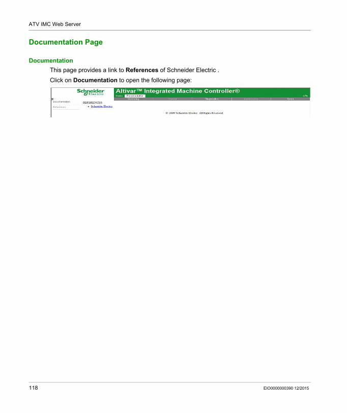
ATV IMC Web Server
Documentation Page
Documentation
This page provides a link to References of Schneider Electric .
Click on Documentation to open the following page:
118 EIO0000000390 12/2015
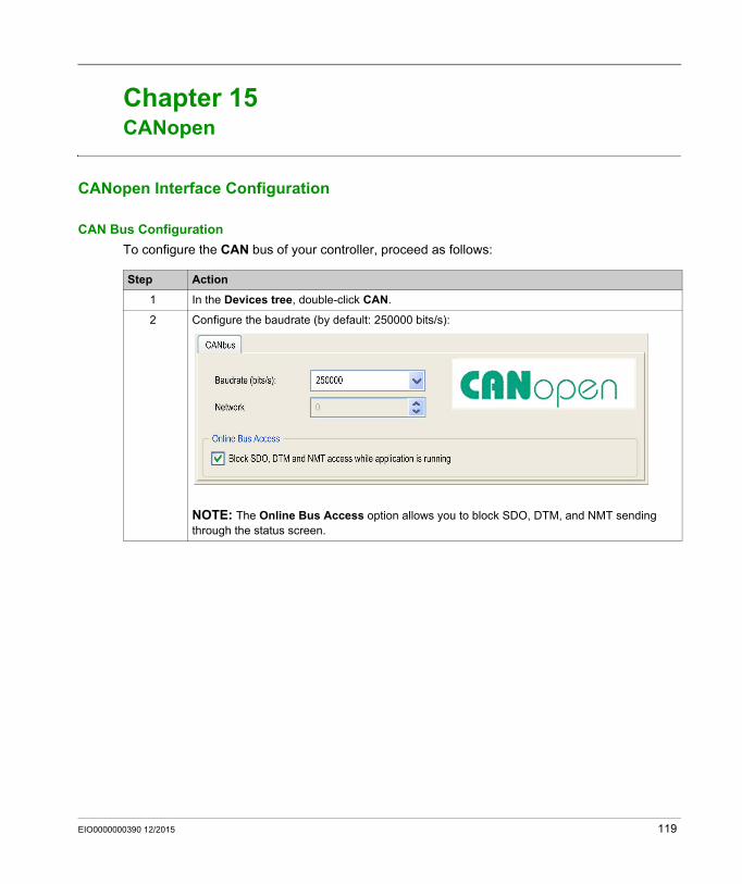
Altivar ATV IMC Drive Controller
CANopen
EIO0000000390 12/2015
CANopen
Chapter 15CANopen
CANopen Interface Configuration
CAN Bus Configuration
To configure the CAN bus of your controller, proceed as follows:
Step Action
1 In the Devices tree, double-click CAN.
2 Configure the baudrate (by default: 250000 bits/s):
NOTE: The Online Bus Access option allows you to block SDO, DTM, and NMT sending through the status screen.
EIO0000000390 12/2015 119
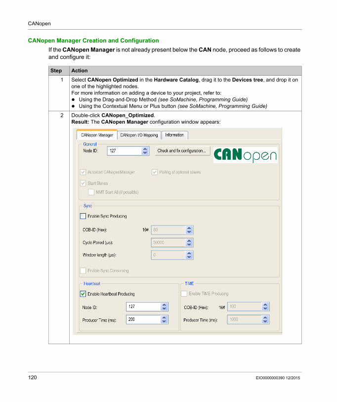
CANopen
CANopen Manager Creation and Configuration
If the CANopen Manager is not already present below the CAN node, proceed as follows to create and configure it:
Step Action
1 Select CANopen Optimized in the Hardware Catalog, drag it to the Devices tree, and drop it on one of the highlighted nodes.For more information on adding a device to your project, refer to: Using the Drag-and-Drop Method (see SoMachine, Programming Guide) Using the Contextual Menu or Plus button (see SoMachine, Programming Guide)
2 Double-click CANopen_Optimized.Result: The CANopen Manager configuration window appears:
120 EIO0000000390 12/2015
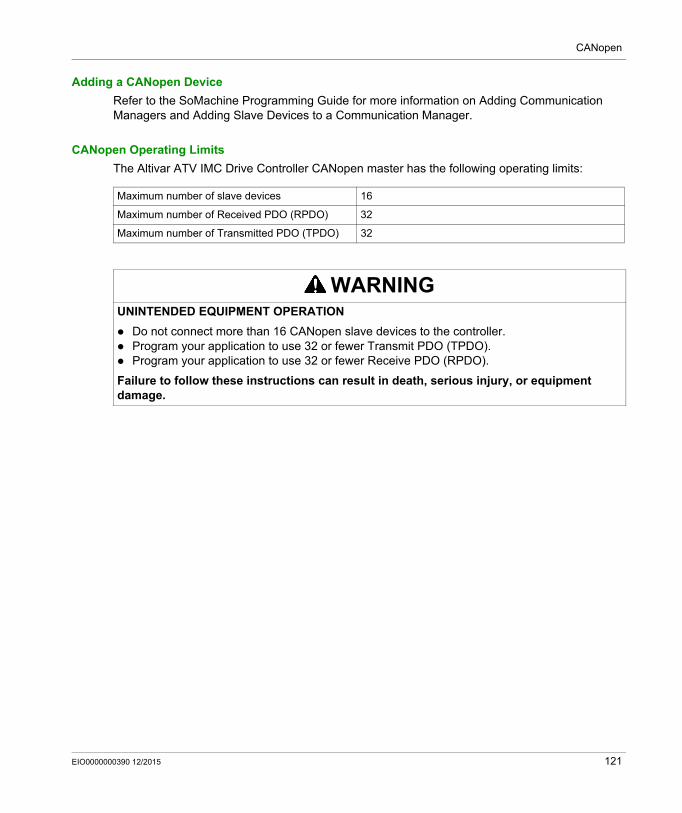
CANopen
Adding a CANopen Device
Refer to the SoMachine Programming Guide for more information on Adding Communication Managers and Adding Slave Devices to a Communication Manager.
CANopen Operating Limits
The Altivar ATV IMC Drive Controller CANopen master has the following operating limits:
Maximum number of slave devices 16
Maximum number of Received PDO (RPDO) 32
Maximum number of Transmitted PDO (TPDO) 32
WARNINGUNINTENDED EQUIPMENT OPERATION
Do not connect more than 16 CANopen slave devices to the controller. Program your application to use 32 or fewer Transmit PDO (TPDO). Program your application to use 32 or fewer Receive PDO (RPDO).
Failure to follow these instructions can result in death, serious injury, or equipment damage.
EIO0000000390 12/2015 121

CANopen
122 EIO0000000390 12/2015
Altivar ATV IMC Drive Controller
Connecting ATV IMC to a PC
EIO0000000390 12/2015
Connecting ATV IMC to a PC
Chapter 16Connecting ATV IMC to a PC
Connecting the Altivar ATV IMC Drive Controller to a PC
Introduction
To transfer and run applications, connect the Altivar ATV IMC Drive Controller to a PC with a properly installed version of SoMachine.
You can connect the Altivar ATV IMC Drive Controller to the PC by means of two different ways: USB-cable Ethernet connection
NOTE: To use the communication ports of the PC, stop the CoDeSys gateway by right-clicking the CoDeSys Gateway SysTray (running) icon from the taskbar and selecting the command Stop Gateway. This is mandatory if you want to use the Ethernet cable.
The communication cable should be connected to the PC first to minimize the possibility of electrostatic discharge affecting the controller.
NOTE: Only 1 controller should be connected to a computer at any given time. Do not connect multiple controllers simultaneously.
NOTICEINOPERABLE EQUIPMENT
Always connect the communication cable to the PC before connecting it to the controller.
Failure to follow these instructions can result in equipment damage.
EIO0000000390 12/2015 123
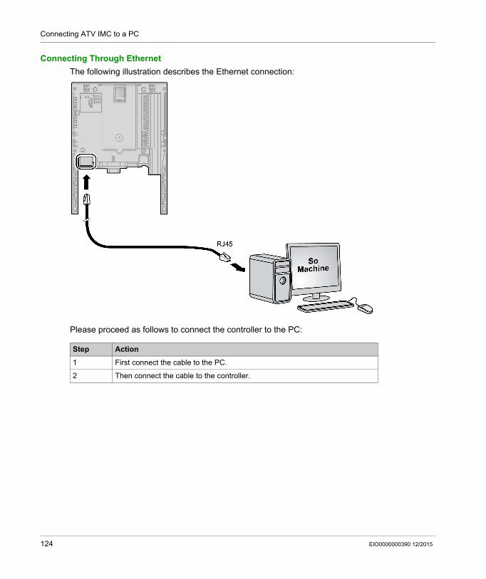
Connecting ATV IMC to a PC
Connecting Through Ethernet
The following illustration describes the Ethernet connection:
Please proceed as follows to connect the controller to the PC:
Step Action
1 First connect the cable to the PC.
2 Then connect the cable to the controller.
124 EIO0000000390 12/2015
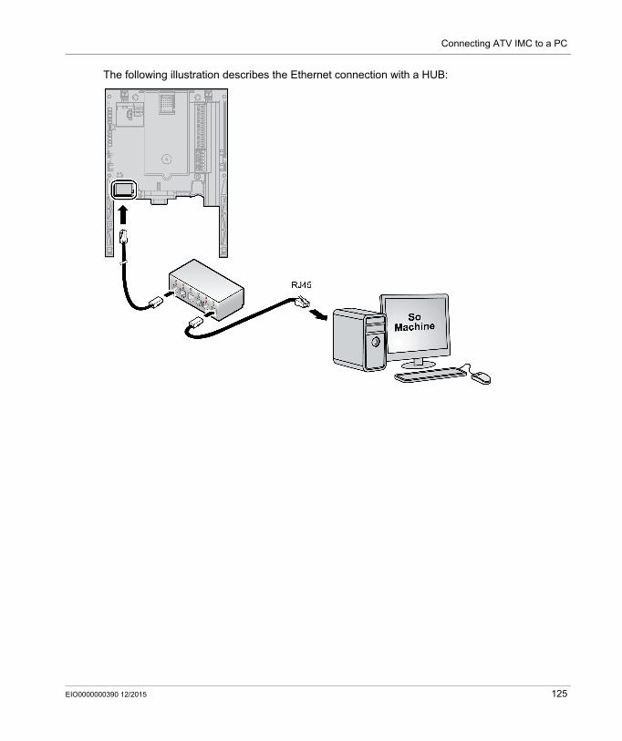
Connecting ATV IMC to a PC
The following illustration describes the Ethernet connection with a HUB:
EIO0000000390 12/2015 125
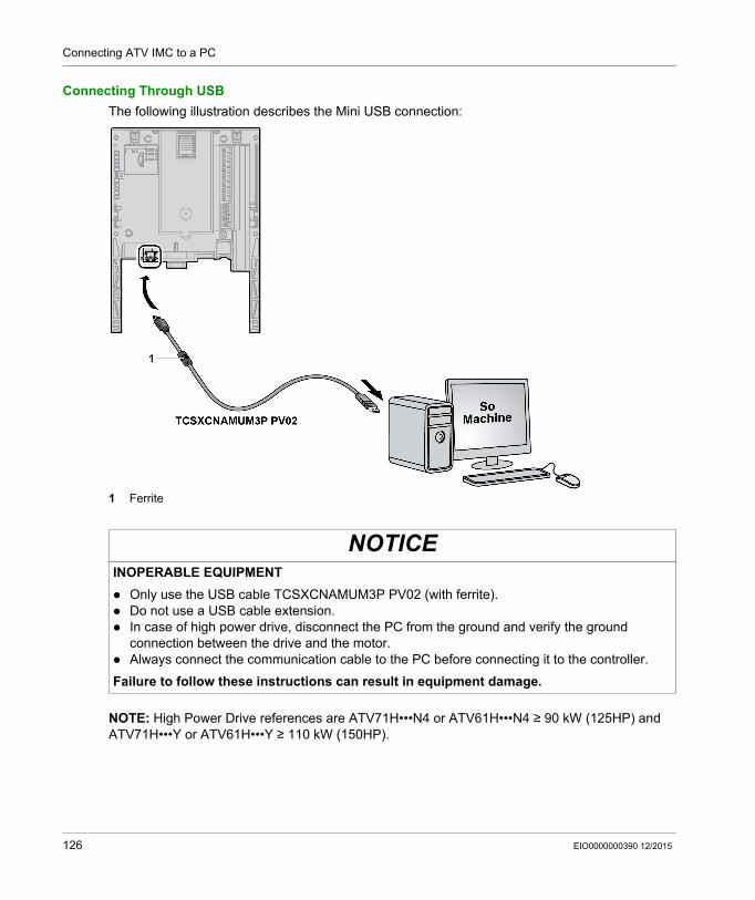
Connecting ATV IMC to a PC
Connecting Through USB
The following illustration describes the Mini USB connection:
1 Ferrite
NOTE: High Power Drive references are ATV71H•••N4 or ATV61H•••N4 ≥ 90 kW (125HP) and ATV71H•••Y or ATV61H•••Y ≥ 110 kW (150HP).
NOTICEINOPERABLE EQUIPMENT
Only use the USB cable TCSXCNAMUM3P PV02 (with ferrite). Do not use a USB cable extension. In case of high power drive, disconnect the PC from the ground and verify the ground
connection between the drive and the motor. Always connect the communication cable to the PC before connecting it to the controller.
Failure to follow these instructions can result in equipment damage.
126 EIO0000000390 12/2015
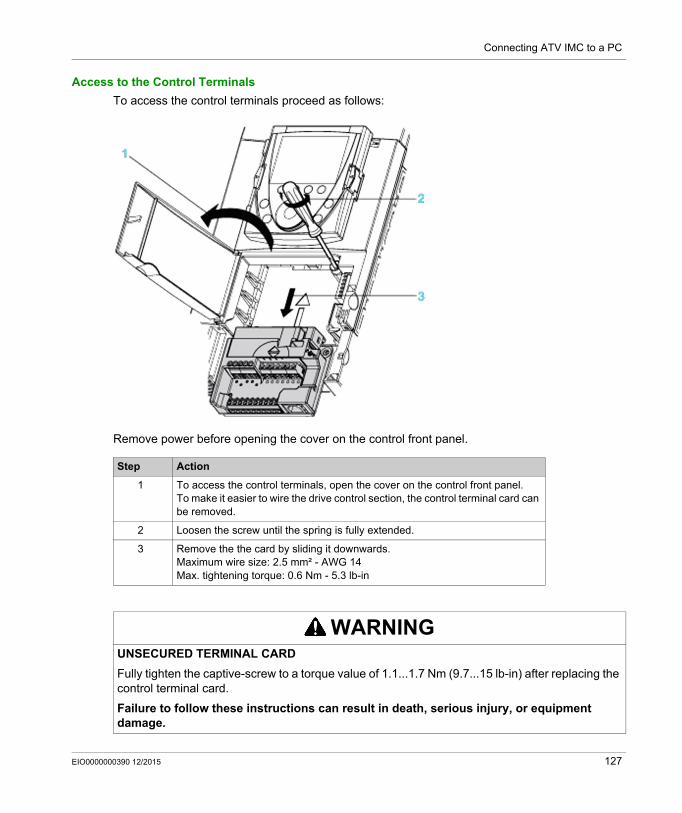
Connecting ATV IMC to a PC
Access to the Control Terminals
To access the control terminals proceed as follows:
Remove power before opening the cover on the control front panel.
Step Action
1 To access the control terminals, open the cover on the control front panel.To make it easier to wire the drive control section, the control terminal card can be removed.
2 Loosen the screw until the spring is fully extended.
3 Remove the the card by sliding it downwards.Maximum wire size: 2.5 mm² - AWG 14Max. tightening torque: 0.6 Nm - 5.3 lb-in
WARNINGUNSECURED TERMINAL CARD
Fully tighten the captive-screw to a torque value of 1.1...1.7 Nm (9.7...15 lb-in) after replacing the control terminal card.
Failure to follow these instructions can result in death, serious injury, or equipment damage.
EIO0000000390 12/2015 127

Connecting ATV IMC to a PC
128 EIO0000000390 12/2015
Altivar ATV IMC Drive Controller
Changing the ATV IMC Firmware
EIO0000000390 12/2015
Changing the ATV IMC Firmware
Chapter 17Changing the ATV IMC Firmware
Overview
The firmware of the Altivar ATV IMC Drive Controller can be changed using: ATV IMC firmware loader software SoMachine Central
What Is in This Chapter?
This chapter contains the following topics:
Topic Page
Changing the Altivar ATV IMC Drive Controller Firmware 130
Changing the Altivar ATV IMC Drive Controller firmware with SoMachine Central 134
EIO0000000390 12/2015 129
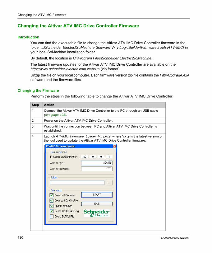
Changing the ATV IMC Firmware
Changing the Altivar ATV IMC Drive Controller Firmware
Introduction
You can find the executable file to change the Altivar ATV IMC Drive Controller firmware in the folder ...\Schneider Electric\SoMachine Software\Vx.y\LogicBuilder\Firmware\Tools\ATV-IMC\ in your local SoMachine installation folder.
By default, the location is C:\Program Files\Schneider Electric\SoMachine.
The latest firmware updates for the Altivar ATV IMC Drive Controller are available on the http://www.schneider-electric.com website (zip format).
Unzip the file on your local computer. Each firmware version zip file contains the FmwUpgrade.exe software and the firmware files.
Changing the Firmware
Perform the steps in the following table to change the Altivar ATV IMC Drive Controller:
Step Action
1 Connect the Altivar ATV IMC Drive Controller to the PC through an USB cable (see page 123).
2 Power on the Altivar ATV IMC Drive Controller.
3 Wait until the connection between PC and Altivar ATV IMC Drive Controller is established.
4 Launch ATVIMC_Firmware_Loader_Vx.y.exe, where Vx .y is the latest version of the tool used to update the Altivar ATV IMC Drive Controller firmware.
130 EIO0000000390 12/2015
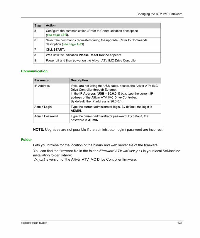
Changing the ATV IMC Firmware
Communication
NOTE: Upgrades are not possible if the administrator login / password are incorrect.
Folder
Lets you browse for the location of the binary and web server file of the firmware.
You can find the firmware file in the folder \Firmware\ATV-IMC\Vx.y.z.t in your local SoMachine installation folder, where:Vx.y.z.t is version of the Altivar ATV IMC Drive Controller firmware.
5 Configure the communication (Refer to Communication description (see page 131)).
6 Select the commands requested during the upgrade (Refer to Commands description (see page 132)).
7 Click START.
8 Wait until the indication Please Reset Device appears.
9 Power off and then power on the Altivar ATV IMC Drive Controller.
Step Action
Parameter Description
IP Address If you are not using the USB cable, access the Altivar ATV IMC Drive Controller through Ethernet.In the IP Address (USB = 90.0.0.1) box, type the current IP address of the Altivar ATV IMC Drive Controller.By default, the IP address is 90.0.0.1.
Admin Login Type the current administrator login. By default, the login is ADMIN.
Admin Password Type the current administrator password. By default, the password is ADMIN.
EIO0000000390 12/2015 131
Changing the ATV IMC Firmware
Command
After clicking START, the selected commands are realized one after the other.
Action Description
Download Firmware This action copies the firmware files from the local PC to the controller file-system disk.The files contain the firmware information.
Download DefWebFile This action copies the file (DefWebSrv.bin) from the local PC to the controller file-system disk.The file contains all the files necessary to upgrade the entire web site.
Update Web Site This action updates the entire web site from the current file DefWebSrv.bin present in the Altivar ATV IMC Drive Controller file-system.This command will not run if the firmware is not present.
NOTE: Empty your Internet web browser cache after using this command.
Delete CodeSysSp.cfg This action deletes the file (CodeSysSp.cfg) from the controller file-system disk.The file contains several parameters for the application, as the current application used or the RUN command at start-up. During the start-up of the Altivar ATV IMC Drive Controller, if this file is unavailable, a default one is created with the default application parameters.
Delete DefWebFile This action deletes the file (DefWebSrv.bin) from the controller file-system disk.
NOTE: The file DefWebSrv.bin takes a lot of space in the controller; hence, delete it after performing the Update Web Site command.
132 EIO0000000390 12/2015
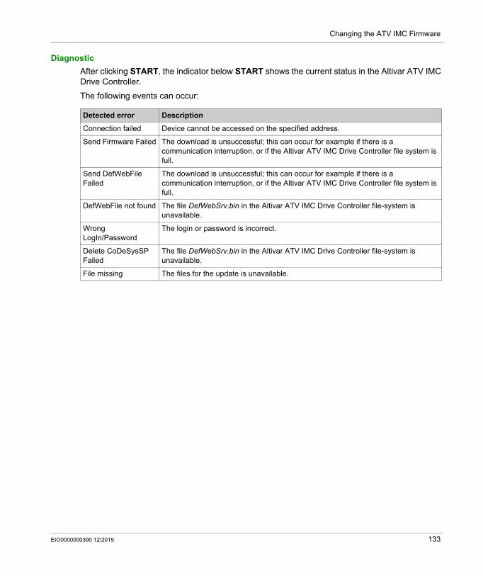
Changing the ATV IMC Firmware
Diagnostic
After clicking START, the indicator below START shows the current status in the Altivar ATV IMC Drive Controller.
The following events can occur:
Detected error Description
Connection failed Device cannot be accessed on the specified address.
Send Firmware Failed The download is unsuccessful; this can occur for example if there is a communication interruption, or if the Altivar ATV IMC Drive Controller file system is full.
Send DefWebFile Failed
The download is unsuccessful; this can occur for example if there is a communication interruption, or if the Altivar ATV IMC Drive Controller file system is full.
DefWebFile not found The file DefWebSrv.bin in the Altivar ATV IMC Drive Controller file-system is unavailable.
Wrong LogIn/Password
The login or password is incorrect.
Delete CoDeSysSP Failed
The file DefWebSrv.bin in the Altivar ATV IMC Drive Controller file-system is unavailable.
File missing The files for the update is unavailable.
EIO0000000390 12/2015 133
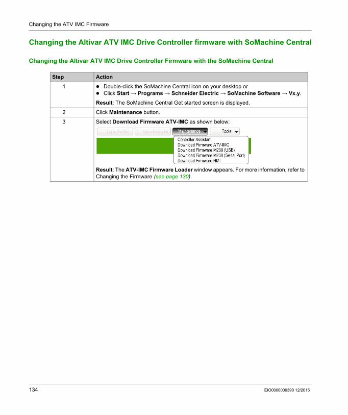
Changing the ATV IMC Firmware
Changing the Altivar ATV IMC Drive Controller firmware with SoMachine Central
Changing the Altivar ATV IMC Drive Controller Firmware with the SoMachine Central
Step Action
1 Double-click the SoMachine Central icon on your desktop or Click Start → Programs → Schneider Electric → SoMachine Software → Vx.y.
Result: The SoMachine Central Get started screen is displayed.
2 Click Maintenance button.
3 Select Download Firmware ATV-IMC as shown below:
Result: The ATV-IMC Firmware Loader window appears. For more information, refer to Changing the Firmware (see page 130).
134 EIO0000000390 12/2015

Altivar ATV IMC Drive Controller
Compatibility
EIO0000000390 12/2015
Compatibility
Chapter 18Compatibility
Software and Firmware Compatibilities
SoMachine Compatibility and Migration
Software and Firmware compatibilities are described in the SoMachine Compatibility and Migration User Guide.
EIO0000000390 12/2015 135

Compatibility
136 EIO0000000390 12/2015
Altivar ATV IMC Drive Controller
Glossary
EIO0000000390 12/2015
Glossary
A
AMOADrive parameter that contains the Modbus address of the ATV IMC drive controller.
analog inputConverts received voltage or current levels into numerical values. You can store and process these values within the logic controller.
analog outputConverts numerical values within the logic controller and sends out proportional voltage or current levels.
applicationA program including configuration data, symbols, and documentation.
ASCII(American standard code for Information Interchange) A protocol for representing alphanumeric characters (letters, numbers, certain graphics, and control characters).
ATVThe model prefix for Altivar drives (for example, ATV312 refers to the Altivar 312 variable speed drive).
AWG(American wire gauge) The standard that specifies wire section sizes in North America.
B
BCD(binary coded decimal) The format that represents decimal numbers between 0 and 9 with a set of 4 bits (a nybble/nibble, also titled as half byte). In this format, the 4 bits used to encode decimal numbers have an unused range of combinations.
For example, the number 2,450 is encoded as 0010 0100 0101 0000.
BOOL(boolean) A basic data type in computing. A BOOL variable can have one of these values: 0 (FALSE), 1 (TRUE). A bit that is extracted from a word is of type BOOL; for example, %MW10.4 is a fifth bit of memory word number 10.
Boot application(boot application) The binary file that contains the application. Usually, it is stored in the controller and allows the controller to boot on the application that the user has generated.
EIO0000000390 12/2015 137
Glossary
BOOTP(bootstrap protocol) A UDP network protocol that can be used by a network client to automatically obtain an IP address (and possibly other data) from a server. The client identifies itself to the server using the client MAC address. The server, which maintains a pre-configured table of client device MAC addresses and associated IP addresses, sends the client its pre-configured IP address. BOOTP was originally used as a method that enabled diskless hosts to be remotely booted over a network. The BOOTP process assigns an infinite lease of an IP address. The BOOTP service utilizes UDP ports 67 and 68.
byteA type that is encoded in an 8-bit format, ranging from 00 hex to FF hex.
C
CANopenAn open industry-standard communication protocol and device profile specification (EN 50325-4).
CFC(continuous function chart) A graphical programming language (an extension of the IEC 61131-3 standard) based on the function block diagram language that works like a flowchart. However, no networks are used and free positioning of graphic elements is possible, which allows feedback loops. For each block, the inputs are on the left and the outputs on the right. You can link the block outputs to the inputs of other blocks to create complex expressions.
controllerAutomates industrial processes (also known as programmable logic controller or programmable controller).
138 EIO0000000390 12/2015
Glossary
D
DHCP(dynamic host configuration protocol) An advanced extension of BOOTP. DHCP is more advanced, but both DHCP and BOOTP are common. (DHCP can handle BOOTP client requests.)
DINT(double integer type) Encoded in 32-bit format.
DTM(device type manager) Classified into 2 categories: Device DTMs connect to the field device configuration components. CommDTMs connect to the software communication components.
The DTM provides a unified structure for accessing device parameters and configuring, operating, and diagnosing the devices. DTMs can range from a simple graphical user interface for setting device parameters to a highly sophisticated application capable of performing complex real-time calculations for diagnosis and maintenance purposes.
DWORD(double word) Encoded in 32-bit format.
E
encoderA device for length or angular measurement (linear or rotary encoders).
EthernetA physical and data link layer technology for LANs, also known as IEEE 802.3.
F
FBD(function block diagram) One of 5 languages for logic or control supported by the standard IEC 61131-3 for control systems. Function block diagram is a graphically oriented programming language. It works with a list of networks, where each network contains a graphical structure of boxes and connection lines, which represents either a logical or arithmetic expression, the call of a function block, a jump, or a return instruction.
firmwareRepresents the BIOS, data parameters, and programming instructions that constitute the operating system on a controller. The firmware is stored in non-volatile memory within the controller.
flash memoryA non-volatile memory that can be overwritten. It is stored on a special EEPROM that can be erased and reprogrammed.
EIO0000000390 12/2015 139
Glossary
freewheelingWhen a logic controller is in freewheeling scan mode, a new task scan starts as soon as the previous scan has been completed. Contrast with periodic scan mode.
FTP(file transfer protocol) A standard network protocol built on a client-server architecture to exchange and manipulate files over TCP/IP based networks regardless of their size.
functionA programming unit that has 1 input and returns 1 immediate result. However, unlike FBs, it is directly called with its name (as opposed to through an instance), has no persistent state from one call to the next and can be used as an operand in other programming expressions.
Examples: boolean (AND) operators, calculations, conversions (BYTE_TO_INT)
H
hex(hexadecimal)
HMI(human machine interface) An operator interface (usually graphical) for human control over industrial equipment.
I
I/O(input/output)
IEC 61131-3Part 3 of a 3-part IEC standard for industrial automation equipment. IEC 61131-3 is concerned with controller programming languages and defines 2 graphical and 2 textual programming language standards. The graphical programming languages are ladder diagram and function block diagram. The textual programming languages include structured text and instruction list.
IL(instruction list) A program written in the language that is composed of a series of text-based instructions executed sequentially by the controller. Each instruction includes a line number, an instruction code, and an operand (refer to IEC 61131-3).
INT(integer) A whole number encoded in 16 bits.
IP(Internet protocol Part of the TCP/IP protocol family that tracks the Internet addresses of devices, routes outgoing messages, and recognizes incoming messages.
140 EIO0000000390 12/2015
Glossary
L
LD(ladder diagram) A graphical representation of the instructions of a controller program with symbols for contacts, coils, and blocks in a series of rungs executed sequentially by a controller (refer to IEC 61131-3).
LINT(long integer) A whole number encoded in a 64-bit format (4 times INT or 2 times DINT).
LREAL(long real) A floating-point number encoded in a 64-bit format.
LWORD(long word) A data type encoded in a 64-bit format.
M
MAC address(media access control address) A unique 48-bit number associated with a specific piece of hardware. The MAC address is programmed into each network card or device when it is manufactured.
machineConsists of several functions and/or equipment.
MASTA processor task that is run through its programming software. The MAST task has 2 sections: IN: Inputs are copied to the IN section before execution of the MAST task. OUT: Outputs are copied to the OUT section after execution of the MAST task.
ModbusThe protocol that allows communications between many devices connected to the same network.
ms(millisecond)
EIO0000000390 12/2015 141
Glossary
N
networkA system of interconnected devices that share a common data path and protocol for communications.
NMT(network management) CANopen protocols that provide services for network initialization, detected error control, and device status control.
nodeAn addressable device on a communication network.
O
OS(operating system) A collection of software that manages computer hardware resources and provides common services for computer programs.
P
PDO(process data object) An unconfirmed broadcast message or sent from a producer device to a consumer device in a CAN-based network. The transmit PDO from the producer device has a specific identifier that corresponds to the receive PDO of the consumer devices.
Profibus DP(Profibus decentralized peripheral) An open bus system uses an electrical network based on a shielded 2-wire line or an optical network based on a fiber-optic cable. DP transmission allows for high-speed, cyclic exchange of data between the controller CPU and the distributed I/O devices.
programThe component of an application that consists of compiled source code capable of being installed in the memory of a logic controller.
142 EIO0000000390 12/2015
Glossary
R
REALA data type that is defined as a floating-point number encoded in a 32-bit format.
RPDO(receive process data object An unconfirmed broadcast message or sent from a producer device to a consumer device in a CAN-based network. The transmit PDO from the producer device has a specific identifier that corresponds to the receive PDO of the consumer devices.
RTC(real-time clock) A battery-backed time-of-day and calender clock that operates continuously, even when the controller is not powered for the life of the battery.
runA command that causes the controller to scan the application program, read the physical inputs, and write to the physical outputs according to solution of the logic of the program.
S
scanA function that includes: reading inputs and placing the values in memory executing the application program 1 instruction at a time and storing the results in memory using the results to update outputs
SDO(service data object) A message used by the field bus master to access (read/write) the object directories of network nodes in CAN-based networks. SDO types include service SDOs (SSDOs) and client SDOs (CSDOs).
SFC(sequential function chart) A language that is composed of steps with associated actions, transitions with associated logic condition, and directed links between steps and transitions. (The SFC standard is defined in IEC 848. It is IEC 61131-3 compliant.)
SINT(signed integer) A 15-bit value plus sign.
ST(structured text) A language that includes complex statements and nested instructions (such as iteration loops, conditional executions, or functions). ST is compliant with IEC 61131-3.
STOPA command that causes the controller to stop running an application program.
stringA variable that is a series of ASCII characters.
EIO0000000390 12/2015 143
Glossary
T
taskA group of sections and subroutines, executed cyclically or periodically for the MAST task or periodically for the FAST task.
A task possesses a level of priority and is linked to inputs and outputs of the controller. These I/O are refreshed in relation to the task.
A controller can have several tasks.
TCP(transmission control protocol) A connection-based transport layer protocol that provides a simultaneous bi-directional transmission of data. TCP is part of the TCP/IP protocol suite.
TPDO(transmit process data object) An unconfirmed broadcast message or sent from a producer device to a consumer device in a CAN-based network. The transmit PDO from the producer device has a specific identifier that corresponds to the receive PDO of the consumer devices.
U
UDINT(unsigned double integer) Encoded in 32 bits.
UDP(user datagram protocol) A connectionless mode protocol (defined by IETF RFC 768) in which messages are delivered in a datagram (data telegram) to a destination computer on an IP network. The UDP protocol is typically bundled with the Internet protocol. UDP/IP messages do not expect a response, and are therefore ideal for applications in which dropped packets do not require retransmission (such as streaming video and networks that demand real-time performance).
UINT(unsigned integer) Encoded in 16 bits.
W
watchdogA watchdog is a special timer used to ensure that programs do not overrun their allocated scan time. The watchdog timer is usually set to a higher value than the scan time and reset to 0 at the end of each scan cycle. If the watchdog timer reaches the preset value, for example, because the program is caught in an endless loop, an error is declared and the program stopped.
WORDA type encoded in a 16-bit format.
144 EIO0000000390 12/2015
Altivar ATV IMC Drive Controller
Index
EIO0000000390 12/2015
Index
Aaddressing
direct, 70immediate, 70indirect, 70symbolic, 70
CConfiguration of Embedded HSC, 73Controller Configuration
Controller Selection, 64Services, 66
DDownload application, 57
EEthernet, 82
Modbus TCP server, 92Modbus TCP slave device, 89Web server, 103
External Event, 32
HHardware Initialization Values, 50high speed counters, 73
Llibraries, 21library size, 25
MMemory Mapping, 25Memory Organization, 25, 25
EIO0000000390 12/2015
OOutput Behavior, 50, 50, 50Output Forcing, 50
PProtocols
IP, 84
RReboot, 55Remanent variables, 59Reset cold, 54Reset origin, 54Reset warm, 53Run command, 52RUN/STOP function, 68
SSoftware Initialization Values, 50State diagram, 39Stop command, 52
TTask
Cyclic task, 31External Event Task, 32Freewheeling task, 32Types, 31Watchdogs, 33
WWeb server
Ethernet, 103
145

Index
146 EIO0000000390 12/2015