Embed Size (px)
Citation preview
ALUMINUM DOUBLE PUMPER™ CARBURETOR
ULTRA SERIES P/N CFM FINISH COLOR CHOKE
0-76650RD 650 SHINY RED ELECTRIC
0-76650BL 650 SHINY BLUE ELECTRIC
0-76650BK 650 SHINY BLACK ELECTRIC
0-76650HB 650 HARDCORE GRAY™ BLACK ELECTRIC
0-76750RD 750 SHINY RED ELECTRIC
0-76750BL 750 SHINY BLUE ELECTRIC
0-76750BK 750 SHINY BLACK ELECTRIC
0-76750HB 750 HARDCORE GRAY™ BLACK ELECTRIC
0-76850RD 850 SHINY RED ELECTRIC
0-76850BL 850 SHINY BLUE ELECTRIC
0-76850BK 850 SHINY BLACK ELECTRIC
0-76850HB 850 HARDCORE GRAY™ BLACK ELECTRIC
0-76651RD 650 SHINY RED MANUAL
0-76651BL 650 SHINY BLUE MANUAL
0-76651BK 650 SHINY BLACK MANUAL
0-76651HB 650 HARDCORE GRAY™ BLACK MANUAL
0-76751RD 750 SHINY RED MANUAL
0-76751BL 750 SHINY BLUE MANUAL
0-76751BK 750 SHINY BLACK MANUAL
0-76751HB 750 HARDCORE GRAY™ BLACK MANUAL
0-76851RD 850 SHINY RED MANUAL
0-76851BL 850 SHINY BLUE MANUAL
0-76851BK 850 SHINY BLACK MANUAL
0-76851HB 850 HARDCORE GRAY™ BLACK MANUAL
ALUMINUM SERIES P/N CFM FINISH CHOKE
0-4776SA 600 SHINY MANUAL
0-4777SA 650 SHINY MANUAL
0-4778SA 700 SHINY MANUAL
0-4779SA 750 SHINY MANUAL
0-4780SA 800 SHINY MANUAL
0-4781SA 850 SHINY MANUAL
INSTALLATION, TUNING, AND ADJUSTMENT MANUAL 199R10500-1
NOTE: These instructions must be read and fully understood before beginning installation. If this manual is not fully understood, installation should not be attempted. Failure to follow these instructions, including the pictures may result in subsequent system failure.

INTRODUCTION:
IMPORTANT: The Aluminum Double Pumper™ carburetor has been factory wet-flowed and calibrated. The “out of the box” settings should be very close for all adjustments.
NOTE: The Aluminum Double Pumper™ Carburetor kit has not yet been submitted for emissions testing and therefore, has not
received an Executive Order Exemption from the California Resources Board. This means that your vehicle will NOT be “Smog Legal” in all 50 states with this kit installed.
WARNING: If you are using this carburetor with a GM overdrive transmission TH700R4 or a TH200R4, you must use a transmission kickdown cable bracket (Holley® P/N 20-95) and stud and kickdown throttle bracket (Holley® P/N 20-121). Otherwise, SEVERE transmission damage WILL result. This carburetor is not designed to work with ANY other automatic overdrive transmissions.
These carburetors have been designed and calibrated as a universal replacement carburetor for passenger cars and light truck applications equipped with V-6 and V-8 engines. It is designed for use on “square” flange intake manifolds. Carburetor adapters are not recommended to adapt to “spread” bore intake manifolds, since adapters may have an adverse effect on cylinder-to-cylinder distribution and ultimately, total engine performance. However, some manifolds may be universal.
REMOVAL:
1. Remove the air cleaner, exercising care to carefully detach any vacuum lines to the air cleaner and marking them so theycan be reassembled to the air cleaner in the same manner.
2. Remove the existing carburetor by the following procedure:A. Carefully disconnect the fuel line.

WARNING: Carefully protect the open end of the fuel lines, so that no foreign particles can enter. Wrap the end of the fuel line with a clean lint-free cloth.
B. Disconnect and mark all the vacuum lines to the carburetor. C. Disconnect the PCV hose. D. Disconnect the choke rod or heat tubes (if equipped). E. Disconnect and remove the throttle linkage and automatic kickdown linkage. SAVE ALL RETAINING CLIPS.
F. Unbolt and remove the carburetor from the manifold.
3. If the intake manifold is being changed at this time, install the new manifold according to the manifold’s manufacturer’sdirections. Since we are not familiar with all manifold instructions, Holley® cannot accept responsibility for their validity.
INSTALLATION NOTES:
CHRYSLER APPLICATIONS:
WARNING: This carburetor is not designed for use with any Chrysler automatic overdrive transmission. SEVERE transmission damage may result from improper application use.
1. If you are replacing an existing Holley® carburetor, you may need to purchase and install a throttle lever extension (Holley®P/N 20-7) on the carburetor. Remove the throttle stud and nut from the original carburetor. You can purchase a new studfrom your Holley® dealer (Holley® P/N 20-67). Install the stud in the throttle extension lever (Figure 1).
Figure 1—Chrysler applications
FORD APPLICATIONS:
NOTE: Unless replacing an existing Holley® Carburetor, you will need to purchase Holley® P/N 20-91, spring and perch kit, for
Ford automatic transmissions.
1. Install the new throttle ball, lockwasher, and retaining nut to the carburetor throttle lever in the same position as the existingcarburetor.
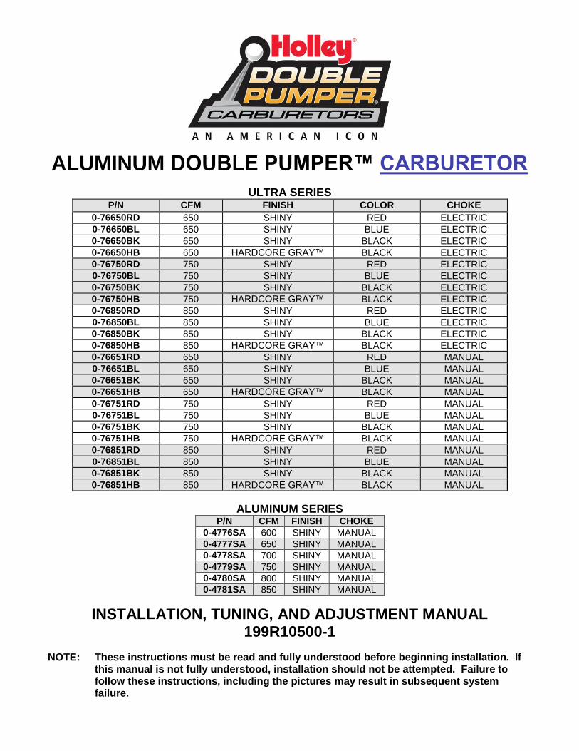
2. Insert the transmission kickdown screw with the retaining clip on the transmission kickdown lever (Figure 2). This assemblymust be installed according to the detailed drawing (Figure 3).
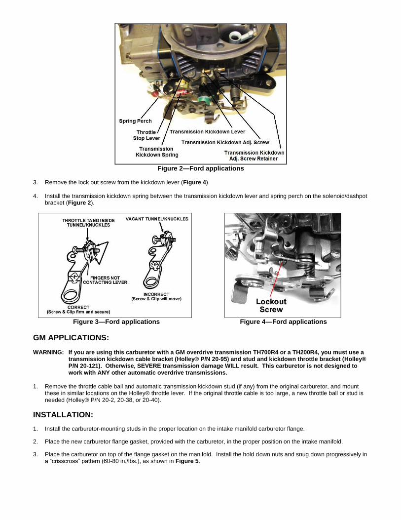
Figure 2—Ford applications
3. Remove the lock out screw from the kickdown lever (Figure 4).
4. Install the transmission kickdown spring between the transmission kickdown lever and spring perch on the solenoid/dashpotbracket (Figure 2).
Figure 3—Ford applications Figure 4—Ford applications
GM APPLICATIONS:
WARNING: If you are using this carburetor with a GM overdrive transmission TH700R4 or a TH200R4, you must use a transmission kickdown cable bracket (Holley® P/N 20-95) and stud and kickdown throttle bracket (Holley® P/N 20-121). Otherwise, SEVERE transmission damage WILL result. This carburetor is not designed to work with ANY other automatic overdrive transmissions.
1. Remove the throttle cable ball and automatic transmission kickdown stud (if any) from the original carburetor, and mountthese in similar locations on the Holley® throttle lever. If the original throttle cable is too large, a new throttle ball or stud isneeded (Holley® P/N 20-2, 20-38, or 20-40).
INSTALLATION:
1. Install the carburetor-mounting studs in the proper location on the intake manifold carburetor flange.
2. Place the new carburetor flange gasket, provided with the carburetor, in the proper position on the intake manifold.
3. Place the carburetor on top of the flange gasket on the manifold. Install the hold down nuts and snug down progressively ina “crisscross” pattern (60-80 in./lbs.), as shown in Figure 5.

Figure 5
WARNING: Overtightening may result in warped or cracked carburetor throttle body.
4. Before connecting the linkage, operate the throttle lever to ensure the correct travel (no sticking or binding), by opening towide-open throttle and back to closed throttle several times. Correct any sticking or binding conditions before proceeding.
5. Reconnect the throttle and transmission kickdown linkage and throttle return spring (Holley® P/N 20-89). Operate thecarburetor throttle lever by hand to ensure the correct travel (no sticking or binding) by opening to wide-open throttle andback to closed throttle several times. Correct any sticking or binding conditions before proceeding.
NOTE: With the engine turned off, have an assistant slowly press the accelerator pedal to the floor, while you watch the
throttle for any sticking or binding. Correct any sticking or binding conditions before proceeding. Also ensure that you are reaching full throttle. Many performance problems are traced to partial throttle openings from improperly adjusted linkage.
Figure 6
6. Reconnect the appropriate vacuum hoses to the carburetor, noting the correct fitting from Figure 6 and 8.
A. The full manifold vacuum source in the front of the throttle body provides vacuum for proper operation of the aircleaner, the pump diverter valve (if equipped), AC/Cruise, and/or the temperature sensing valve. If vacuum for more than one component is needed, use small plastic vacuum “T”s (available at most automotive stores).
B. The timed spark fitting in the choke side of the primary metering block provides vacuum for the operation of the distributor vacuum advance. Connect the hose to the distributor, spark delay valve, and/or temperature sensing valve as originally connected. Again use “T”s as necessary. If any questions arise about the hose connections, consult the proper service manual.
7. Connect the PCV hose to the PCV fitting in the carburetor.
8. Connect the power brake hose to the fitting as shown in Figure 6.

9. Connect the fuel line. (Holley® 34-150 or equivalent)
10. In some cases, the existing fuel line will have to be cut and connected to the fuel line assembly from step 9 with a length ofrubber fuel hose and clamp.
WARNING: During the fuel line installation, DO NOT allow any foreign particles to enter the fuel lines, which could then cause flooding and may result in a fire.
WARNING: Keep the fuel line away from the EGR valve (if equipped) on the intake manifold.
If installation requires cutting the metal fuel line, cut the fuel line with a good tube cutter. This will minimize the chance of producing metal chip particles. If a hacksaw must be used then metal chips must be removed.
WARNING: In all cases where the fuel line has been cut, it is essential that it be clean to ensure that no metal particles enter the fuel bowl after the new carburetor installation. Remove the fuel line at the pump and blow the line clean with compressed air. DO NOT use the procedure where the coil wire is disconnected, the engine cranked for a few revolutions, and the fuel collected in a container. This procedure is unsafe because sparking can occur either at the coil or at the distributor end of the coil wire and ignite any fuel spilled in the engine compartment.
CAUTION: This carburetor contains in line Morain fuel filters. However, the use of a quality in line fuel filter, such as Holley®
P/N 162-523 is mandatory as a safeguard against possible flooding, which could result from unfiltered particles becoming lodged between the fuel inlet needle and its seat. This can result in fire if a spark is present or backfire occurs in the engine compartment. Air cleaner filter elements should be blown clean with compressed air at 6,000 miles and replaced at 12,000 miles to ensure maximum protection.
11. Start the engine and check the fuel lines and inlet fitting for possible leaks.
NOTE: The recommended fuel pressure is 5-7 psi.
12. Recheck to ensure that all existing vacuum hoses are attached properly. Plug any fittings not used.
13. With the engine at operating temperature, set the idle speed to the manufacturer’s specifications (see page 9 for idleadjustment).
14. Shut off the engine and readjust the throttle operated transmission linkage, if necessary. On installations that have akickdown-actuating switch on the passenger’s side of the firewall, it might be necessary to readjust it according to themanufacturer’s service manual.
FORD APPLICATIONS WITH AUTOMATIC TRANSMISSIONS: With the engine off, push the transmission kickdown rod
rearward until it stops and hold it in position. Push the throttle lever rearward to its wide-open throttle position and adjust the transmission kickdown screw to come in contact with the transmission kickdown lever tang.
WARNING: With the engine off, recheck the assembled linkage for sticking and/or proper return to the idle position.
15. Place the air cleaner gasket (supplied) on the sealing flange, and install the air cleaner.
16. With some air cleaner configurations, it may be necessary to use an air cleaner spacer to provide adequate clearancebetween the carburetor and the air cleaner. Holley® offers such a spacer (Holley® P/N 17-13). Depending on the overallheight, obtain the proper length 1/4 x 20 stud and install in the carburetor airhorn. Close the hood slowly to ensureadequate clearance between the air cleaner stud and the hood.
WARNING: Inadequate clearance between the air cleaner and the throttle lever could result in throttle sticking and uncontrolled engine speed. Check the clearance between the throttle lever and air cleaner for proper operation. Check the clearance between the air cleaner and the hood before closing the hood completely.
MAINTENANCE WARNING: Fuel system components, including fuel lines and the carburetor, should be inspected periodically
to ensure no fuel leakage and to ensure the soundness of the hoses. Today’s clean emissions engines provide higher temperatures in the engine compartment. These high temperatures promote faster aging of non-metallic materials.
Hoses that exhibit surface cracks, when bent to 180°, should be replaced. The presence of liquid fuel demands tightening of fittings, hose replacement, and re-torquing of the fuel system component flange nuts. Periodically check the torque on the fuel bowl screws to 25-30 in./lbs. to ensure proper fuel metering.
GENERAL: Some very important factors to optimize efficiency and performance include: Correct engine timing, correct spark
plug gap and heat range, ignition components in good working order, and correct operation of exhaust heat valve.

WARNING: On automatic transmission vehicles only, install the transmission kickdown adjustment screw and black retaining clip, as correctly indicated. Failure to attend to this detail may result in a sticking wide-open throttle or dangerous uncontrolled engine speed.
IMPORTANT: The Aluminum Double Pumper™ carburetor has been factory wet-flowed and calibrated. The “out of the box” settings should be very close for all adjustments. The following tuning section is included ONLY to aid you in fine tuning adjustments.
ELECTRIC CHOKE HOOKUP & ADJUSTMENT:
1. For electric choke hookup, attach the bayonet end of the long electrical lead supplied to the positive terminal on thechoke cap. The other end must be connected to an ignition activated 12-volt source. The distributor side of theignition coil is NOT a 12-volt source. It is a 7-9-volt source after cranking.
WARNING: Connecting the choke cap to the ignition or ignition coil could result in unacceptable choke operation, poor fuel economy, and possible engine misfiring, since the voltage delivered to the spark plugs will be severely reduced by the drain imposed by the choke cap. Suitable ignition activated 12-volt sources are most electrical relays, as well as the leads to accessories, such as windshield wipers. DO NOT connect this wire to the original equipment (O.E.) electric choke source. This may not be a 12V source.
2. A 12”choke ground wire is provided (in the kit) and needs to be attached to a ground source on the intake manifold. The.25” male spade terminal will attach to the negative terminal of the choke cap (see Figure 7). Use the 3/8” ring terminal toattach the wire to the manifold. NOTE: Holley® recommends grounding to the intake manifold. An anodized surface is not
a good conductor of electricity and a proper ground may not be achieved.
Figure 7
3. Check the voltage source with a volt-ohm meter to ensure proper voltage and choke operation.
4. You can control the choke operation by rotating the choke cap. If the choke comes off too soon, loosen the three screwsand rotate the choke cap counterclockwise one notch at a time, until the choke operation is satisfactory. Rotate the chokecap clockwise, if the choke comes off too late. After making the final adjustments, start the engine and make sure thechoke plate opens completely.
A. A choke that comes off too soon could exhibit one or more of the following symptoms: stalling, surging, backfiring,stumbles, or poor vehicle drivability when the vehicle is cold.
B. A choke that comes off too late could exhibit one or more of the following symptoms: black smoke from the tail pipe,poor drivability when cold, poor gas mileage, misses, or rough idle.
5. If choke operation is unsatisfactory and you have adjusted the choke cap in either direction to with unsatisfactory results,recheck your positive electrical line connection.
6. If the fast idle RPM is too low or too high for your preferences, TURN THE ENGINE OFF. Advance the throttle to wide-open, exposing the fast idle set screw below the choke housing (See Figure 8).
7. Using a 1/4” open end wrench, turn the screw clockwise to increase the RPM or counterclockwise to decrease the RPM.The factory setting should give you a 1500-1600 RPM fast idle speed.
NOTE: All vacuum ports must be plugged at this time.
8. Return the throttle to the fast idle position, as described in step 6. Restart the engine, and recheck the fast idle RPM.Repeat steps 6 & 7 until the desired fast idle RPM is met.

MANUAL CHOKE HOOKUP & ADJUSTMENT:
1. Connect the choke control cable (Holley® P/N 45-228) to the choke actuation lever, and lock in place with the choke cablelock screw (Figure 8).
2. Mount the outer sleeve to the cable clamp.
3. Actuate the choke cable through its full range of motion to ensure full choke operation. Adjust the cable position with lockscrew, as necessary.
4. If the fast idle RPM is too low or too high for your preferences, TURN THE ENGINE OFF. Advance the throttle to wide-open, exposing the fast idle set screw below the choke housing (See Figure 8).
5. Using a 1/4” open end wrench, turn the screw clockwise to increase the RPM or counterclockwise to decrease the RPM.The factory setting should give you a 1500-1600 RPM fast idle speed.
NOTE: All vacuum ports must be plugged at this time.
6. Return the throttle to the fast idle position, as described in step 4. Restart the engine, and recheck the fast idle RPM.Repeat steps 4 & 5 until the desired fast idle RPM is met.
Figure 8
IDLE MIXTURE NEEDLES:
Idle mixture needles control the air/fuel mixture at idle. These have been preset at the factory and SHOULD NOT need any adjustments. However, if you feel that adjustment is necessary, you can use the following procedure to do so. When tuning the idle mixture, you’re actually tuning for the best manifold vacuum. Idle mixture needles are found on the primary and secondary metering blocks. If you change one idle mixture needle, you should change the other idle mixture needle by the same amount. Here are the proper steps for setting the idle mixture needles.
1. Attach the vacuum gauge to a manifold vacuum port on the throttle body.
2. The Aluminum Double Pumper™ is a 4 corner idle carburetor which means there are 4 idle mixture screws. Two in theprimary metering block and two on the secondary metering block. Adjust each idle mixture screw (Figures 10 & 11) 1/8 turn
at a time, alternating between all 4 screws. Turn them equally, until you achieve the highest possible vacuum readingwithout adjusting the curb idle speed screw. Turn screws in to lean the mixture. Turn them out to richen the mixture.

Figure 9
3. Now that the idle mixture is set, it may be necessary to go back and reset the idle speed using the curb idle speed screw,as shown in Figure 9.
4. If a vacuum gauge is not available, use a tachometer to obtain the highest RPM.
Figure 10 Figure 11
ROUGH IDLE AND VACUUM LEAKS: If a rough idle persists after the engine has been started and the mixture screws
adjusted, check for manifold vacuum leaks. These could result from unplugged vacuum fittings or a carburetor flange gasket that was torn during installation. Recheck for proper attachment of all vacuum lines and check the lines for cracks. If the manifold was changed, a manifold vacuum leak could occur at the cylinder head/manifold surface due to damaged gaskets or improper torquing. Frequently, manifold vacuum leaks occur from the valley side of the manifold. These are very difficult to detect, unless a discernible whistle can be heard.
NOTE: In most cases, when rough idle occurs after a carburetor/manifold change, they result from manifold vacuum leaks
similar to those described above. Assuring a proper manifold installation rather than assuming the carburetor is not functioning properly will ultimately save time.
FLOAT LEVEL ADJUSTMENT:
NOTE: Do not try to remove the sight glasses. It takes special tools to install these and it is not recommended that they be
removed.
Primary and secondary float adjustments are set at the factory, but variations in fuel pressure could cause a change in these settings. To aid in adjustment of the float levels, clear sight glasses are installed from the factory. The following procedure shows how to make these adjustments:
1. Start the vehicle.
2. Observe the sight glass for the fuel level. If none is seen, the level is too low. If it is higher than the middle of the sightwindow, it is too high. NOTE: A properly set float level will have the fuel level located at the middle or slightly below themiddle of the sight window, as shown by the line in Figure 12.

Figure 12
3. To adjust, shut down the engine.
4. Loosen the lock screw on top of the fuel bowl just enough to allow you to turn the adjusting nut. Hold the screw in positionwith the screwdriver.
5. Using a 5/8” wrench, turn the adjusting nut in the appropriate direction: Clockwise to lower fuel level and counterclockwiseto raise the fuel level.
NOTE: Many customers attempt to adjust the float level down by turning the adjusting nut clockwise, only to see the fuel level
rise through the sight glass. This is due to the float being pushed down into the fuel, therefore displacing the fuel to a higher level. You will find it easier to adjust the float levels, if you rev the engine slightly between adjustments to evacuate the fuel.
6. Turn the adjusting nut in increments of 1/4 of a rotation.
7. Retighten the lock screw.
8. Restart the vehicle and observe the sight window.
9. Repeat steps 1 through 8 as necessary.
SECONDARY FLOAT LEVELS:
Very little fuel is drawn out of the secondary fuel bowls during idle operation. This makes it a little tricky to set the proper float level with the sight glasses. Many customers attempt to adjust the rear float level down by turning the adjusting nut clockwise, only to see the fuel level rise through the sight glass. This is due to the float being pushed down into the fuel, therefore displacing the fuel to a higher level. You will find it easier to adjust the float levels, if you rev the engine slightly by opening the secondaries between adjustments. This can be easily done by rolling the secondary throttle shaft linkage forward on the driver’s side of the vehicle. This will use fuel from the secondary bowl at a much faster rate, allowing the float level to seek the adjustment point that you have set. Once the floats have been set with this procedure, drive the vehicle, and recheck the float level.
ACCELERATOR PUMP TUNING:
The accelerator pump’s purpose is to make up for the lag in fuel delivery to enable the engine speed to increase in response to throttle opening. Differences in vehicle weight, transmissions, and rear axle ratios affect the amount of fuel and the delivery rate that should be provided by the accelerator pump. This may necessitate the customizing of your accelerator pump to your vehicle and its use.
NOTE: The old saying, “if a little is good, a lot is better”, does not apply to the proper tuning of the accelerator pump. Your car’s performance can be just as bad if it receives “too much fuel too soon” as if it receives “too little fuel too late.”
Two factors that affect the accelerator pump’s delivery are the pump cam and the pump shooter (discharge nozzle). The pump cam determines the total volume of fuel and affects delivery rate; the pump shooter affects delivery rate and helps determine the duration of the shot.
In general, the #1 location on the pump cams provides a moderate initial delivery and has a greater final delivered volume. The #2 locations on the pump cams provide a greater initial delivery and have a lesser total delivered volume. The pump shooters have a number stamped on their casting, which designates the shooter size in thousandths of an inch, i.e., a #25 shooter has a
.025” discharge orifice. The smaller diameter nozzles lengthen the pump shot duration and are used with heavier vehicles or with vehicles equipped with lower numerical rear axle ratios. Larger diameter nozzles (.035 - .037) shorten the pump shot duration, but deliver a greater initial volume of fuel. These sizes should be used on applications where engine speed will increase rapidly (vehicles with good power-to-weight ratios). Best acceleration is achieved when the accelerator pump delivers the lean, best-power, air/fuel ratio to the engine; not when the maximum volume of fuel is supplied.
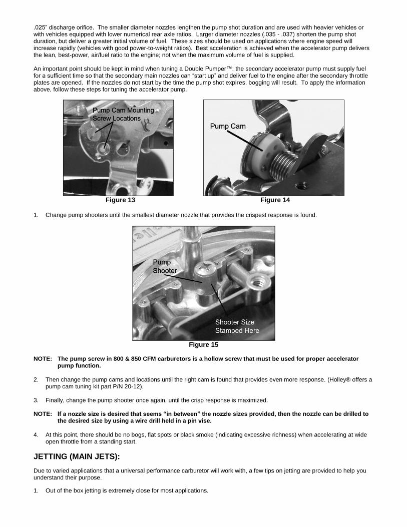
An important point should be kept in mind when tuning a Double Pumper™; the secondary accelerator pump must supply fuel for a sufficient time so that the secondary main nozzles can “start up” and deliver fuel to the engine after the secondary throttle plates are opened. If the nozzles do not start by the time the pump shot expires, bogging will result. To apply the information above, follow these steps for tuning the accelerator pump.
Figure 13 Figure 14
1. Change pump shooters until the smallest diameter nozzle that provides the crispest response is found.
Figure 15
NOTE: The pump screw in 800 & 850 CFM carburetors is a hollow screw that must be used for proper accelerator pump function.
2. Then change the pump cams and locations until the right cam is found that provides even more response. (Holley® offers apump cam tuning kit part P/N 20-12).
3. Finally, change the pump shooter once again, until the crisp response is maximized.
NOTE: If a nozzle size is desired that seems “in between” the nozzle sizes provided, then the nozzle can be drilled to the desired size by using a wire drill held in a pin vise.
4. At this point, there should be no bogs, flat spots or black smoke (indicating excessive richness) when accelerating at wideopen throttle from a standing start.
JETTING (MAIN JETS):
Due to varied applications that a universal performance carburetor will work with, a few tips on jetting are provided to help you understand their purpose.
1. Out of the box jetting is extremely close for most applications.

2. Carburetors are calibrated at sea level. Decrease the jet size primary and secondary, one number for every 2000 ft.increase in altitude.
3. Holley® jets are broached, flowed, and stamped according to flow rate. NEVER drill jets, as this seriously alters flowcharacteristics. Stamped numbers are reference numbers and DO NOT indicate drill size.
4. In most cases it will be unnecessary to increase jet size more than four numbers greater than out of the box jetting.
Exceptions could arise when the carburetor is mounted on a very large volume, plenum-ram manifold.
5. Spark plugs provide the best indication of proper jetting. Consult an ignition manual for proper reading of spark plugs.


![Mike's Carburetor Parts · Mike's Carburetor Parts. RETOR HOLLEY MODEL 2.300 sidercd ors idle which ahead tly to e fir] a ment the t built by s - (l ruel Fuel All fir-sl at a four](https://img.pdfslide.net/doc/110x75/5d47cc0b88c993da7b8b7f33/mikes-carburetor-mikes-carburetor-parts-retor-holley-model-2300-sidercd.jpg)