Embed Size (px)
Citation preview
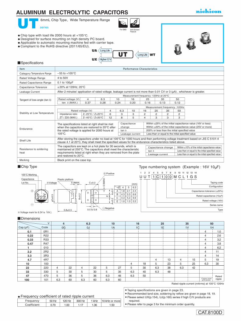
ALUMINUM ELECTROLYTIC CAPACITORS
CAT.8100D
UT series
6mmL Chip Type , Wide Temperature Range
Chip type with load life 2000 hours at +105°C.Designed for surface mounting on high density PC board.Applicable to automatic mounting machine fed with carrier tape.Compliant to the RoHS directive (2011/65/EU).
Specifications
Category Temperature Range
Rated Voltage Range
Rated Capacitance Range
Capacitance Tolerance
Leakage Current
Tangent of loss angle (tan δ)
Stability at Low Temperature
Endurance
Shelf Life
Resistance to solderingheat
Marking
Performance CharacteristicsItem
–55 to +105°C
4 to 50V
0.1 to 100µF
± 20% at 120Hz, 20°C
After 2 minutes' application of rated voltage, leakage current is not more than 0.01 CV or 3 (µA) , whichever is greater.
Black print on the case top.
Measurement frequency :120Hz at 20°C
The specifications listed at right shall be met when the capacitors are restored to 20°C after the rated voltage is applied for 2000 hours at 105°C.
After storing the capacitors under no load at 105°C for 1000 hours and then performing voltage treatment based on JIS C 5101-4 clause 4.1 at 20°C, they shall meet the specified values for the endurance characteristics listed above.
U1
U2
T3
14
C5
16
07
08
M9
C10
L11
112
G13
S14
Configuration
Taping code
Capacitance tolerance (±20%)
Rated voltage (16V)
Rated capacitance (10μF)
Series name
Type
Voltage
Capacitance
105°C Marking
Lot No.
A2P
10 16V
Plastic platform0.3MAX.
5.8±0.3
φD±
0.5
B±
0.2
C±0.2
0.5M
AX
.
A±
0.2
A
±0.
2
E
Positive
Negative
AB
CE
4
1.8
4.3
4.3
1.0
5
2.1
5.3
5.3
1.3
6.3
2.4
6.6
6.6
2.2
0.5 to 0.8
(mm)φD
Voltage mark for 6.3V is 6V .
Chip Type Type numbering system (Example : 16V 10µF)
Rated voltage (V)
tan δ (MAX.)4
0.3750
0.1235
0.1325
0.1616
0.2010
0.246.3
0.28
Measurement frequency :120Hz
Z–25°C / Z+20°C
Z–40°C / Z+20°C
Rated voltage (V)
Impedance ratioZT / Z20 (MAX.)
46
12
6.338
1035
1624
2523
3523
5023
The capacitors are kept on a hot plate for 30 seconds, which is maintained at 250°C. The capacitors shall meet the characteristic requirements listed at right when they are removed from the plate and restored to 20°C.
tan δ
Capacitance
change
200% or less than the initial specified valueLeakage current Less than or equal to the initial specified value
Within ±25% of the initial capacitance value (16V or less) Within ±20% of the initial capacitance value (25V or more)
Capacitance change
Leakage current
tan δ
Within ±10% of the initial capacitance value
Less than or equal to the initial specified valueLess than or equal to the initial specified value
Frequency coefficient of rated ripple current
CoefficientFrequency 50 Hz 120 Hz 300 Hz 1 kHz 10 kHz or more
0.70 1.00 1.17 1.36 1.50
Dimensions
Rated ripple current (mArms) at 105°C 120Hz
0.1 0.22 0.33 0.47 1 2.2 3.3 4.7 10 22 33 47 100
0R1R22R33R470102R23R34R7100220330470101
4 5 5 6.3
22303660
0G4
0J6.3
1A10
1C16
1E25
1V35
1H50
4 5 5 6.3
22303660
5 5 6.3 6.3
27354660
4 5 6.3 6.3
18304050
4 5 6.3 6.3
13233848
4 5 6.3
152542
4 4 4 4 4 4 4 5 6.3
1.0 2.6 3.2 3.8 6.2 11 14 19 30
Allowableripple
Cap.(µF)
V
Code
RatedrippleCase size
φ D (mm)
UTUA
Long Life WTHigher C/V
Long Life
UX
Taping specifications are given in page 23. Recommended land size, soldering by reflow are given in page 18, 19. Please select UX(p.154), UJ(p.160) series if high C/V products are
required. Please refer to page 3 for the minimum order quantity.