Embed Size (px)
Citation preview
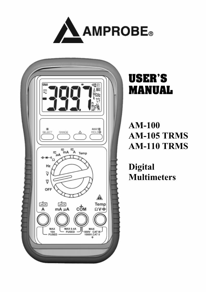
USER'S MANUAL
AM-100 AM-105 TRMS AM-110 TRMS Digital Multimeters
1 1) SAFETY This manual contains information and warnings that must be followed for operating the instrument safely and maintaining the instrument in a safe operating condition. If the instrument is used in a manner not specified by the manufacturer, the protection provided by the instrument may be impaired. The meter is intended only for indoor use. The meter (all versions) is protected, against the users, by double insulation per CSA C22.2 No. 1010-1-92, EN61010-1(1995) and IEC61010-1(1995) to CAT II 1000V & CAT III 600V. Protection-reinforced CE version Terminals (to COM) ratings:
V : Category II 1000 Volts AC & DC, and Category III 600 Volts AC & DC. A / mAµA : Category III 500 Volts AC and 300 Volts DC.
PER IEC61010 OVERVOLTAGE INSTALLATION CATEGORY OVERVOLTAGE CATEGORY II Equipment of OVERVOLTAGE CATEGORY II is energy-consuming equipment to be supplied from the fixed installation. Note – Examples include household, office, and laboratory appliances. OVERVOLTAGE CATEGORY III Equipment of OVERVOLTAGE CATEGORY III is equipment in fixed installations. Note – Examples include switches in the fixed installation and some equipment for industrial use with permanent connection to the fixed installation. Terms in this manual: WARNING identifies conditions and actions that could result in serious injury or even
death to the user. CAUTION identifies conditions and actions that could cause damage or malfunction
in the instrument.
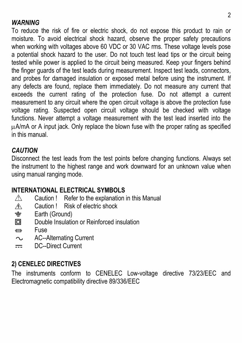
2 WARNING To reduce the risk of fire or electric shock, do not expose this product to rain or moisture. To avoid electrical shock hazard, observe the proper safety precautions when working with voltages above 60 VDC or 30 VAC rms. These voltage levels pose a potential shock hazard to the user. Do not touch test lead tips or the circuit being tested while power is applied to the circuit being measured. Keep your fingers behind the finger guards of the test leads during measurement. Inspect test leads, connectors, and probes for damaged insulation or exposed metal before using the instrument. If any defects are found, replace them immediately. Do not measure any current that exceeds the current rating of the protection fuse. Do not attempt a current measurement to any circuit where the open circuit voltage is above the protection fuse voltage rating. Suspected open circuit voltage should be checked with voltage functions. Never attempt a voltage measurement with the test lead inserted into the µA/mA or A input jack. Only replace the blown fuse with the proper rating as specified in this manual. CAUTION Disconnect the test leads from the test points before changing functions. Always set the instrument to the highest range and work downward for an unknown value when using manual ranging mode. INTERNATIONAL ELECTRICAL SYMBOLS ! Caution ! Refer to the explanation in this Manual Caution ! Risk of electric shock Earth (Ground) Double Insulation or Reinforced insulation Fuse AC--Alternating Current DC--Direct Current 2) CENELEC DIRECTIVES The instruments conform to CENELEC Low-voltage directive 73/23/EEC and Electromagnetic compatibility directive 89/336/EEC
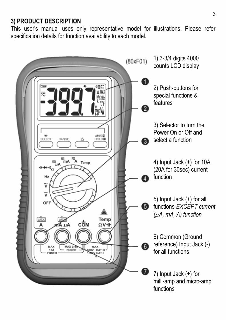
3 3) PRODUCT DESCRIPTION This user's manual uses only representative model for illustrations. Please refer specification details for function availability to each model.
1) 3-3/4 digits 4000 counts LCD display 2) Push-buttons for special functions & features 3) Selector to turn the Power On or Off and select a function 4) Input Jack (+) for 10A (20A for 30sec) current function 5) Input Jack (+) for all functions EXCEPT current (µA, mA, A) function 6) Common (Ground reference) Input Jack (-) for all functions 7) Input Jack (+) for milli-amp and micro-amp functions
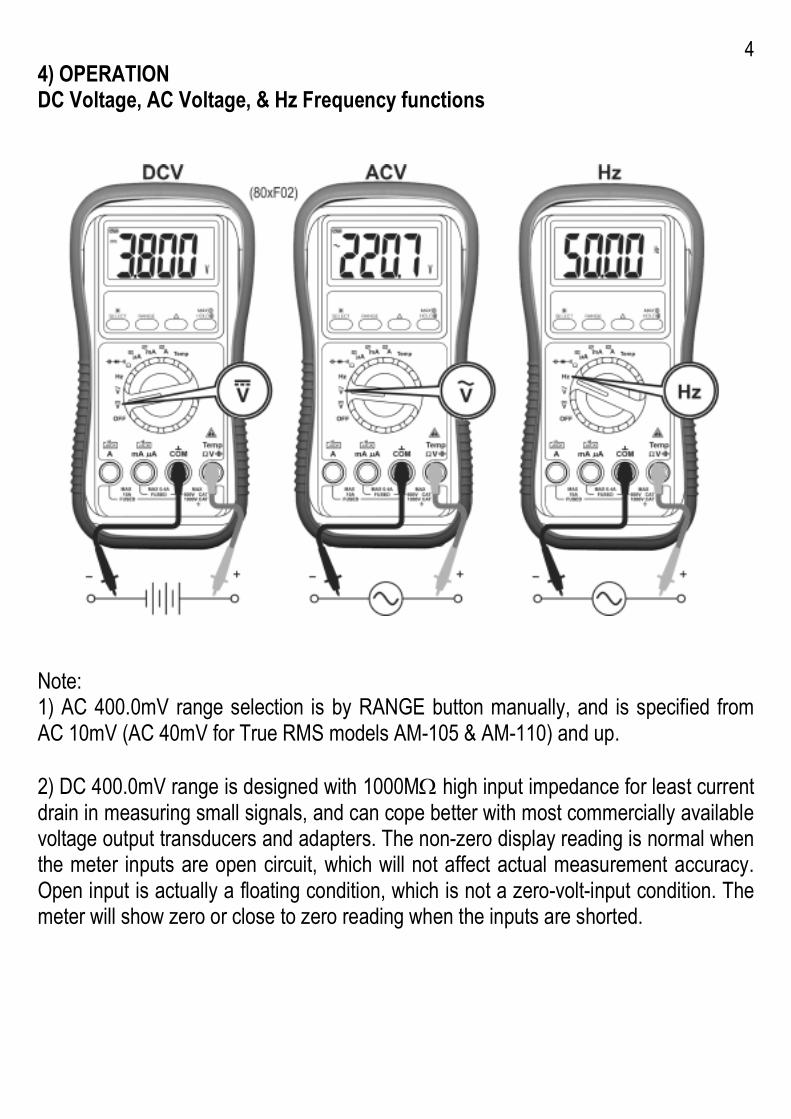
4 4) OPERATION DC Voltage, AC Voltage, & Hz Frequency functions
Note: 1) AC 400.0mV range selection is by RANGE button manually, and is specified from AC 10mV (AC 40mV for True RMS models AM-105 & AM-110) and up. 2) DC 400.0mV range is designed with 1000MΩ high input impedance for least current drain in measuring small signals, and can cope better with most commercially available voltage output transducers and adapters. The non-zero display reading is normal when the meter inputs are open circuit, which will not affect actual measurement accuracy. Open input is actually a floating condition, which is not a zero-volt-input condition. The meter will show zero or close to zero reading when the inputs are shorted.
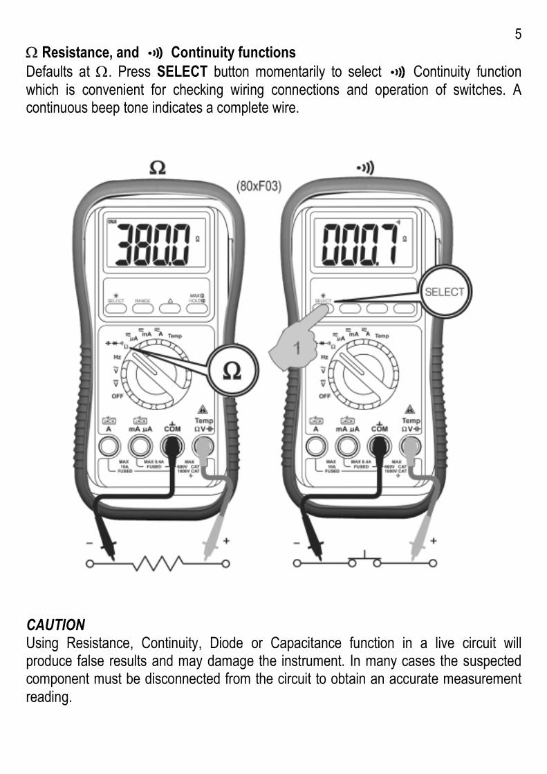
5 Ω Resistance, and Continuity functions Defaults at Ω. Press SELECT button momentarily to select Continuity function which is convenient for checking wiring connections and operation of switches. A continuous beep tone indicates a complete wire.
CAUTION Using Resistance, Continuity, Diode or Capacitance function in a live circuit will produce false results and may damage the instrument. In many cases the suspected component must be disconnected from the circuit to obtain an accurate measurement reading.
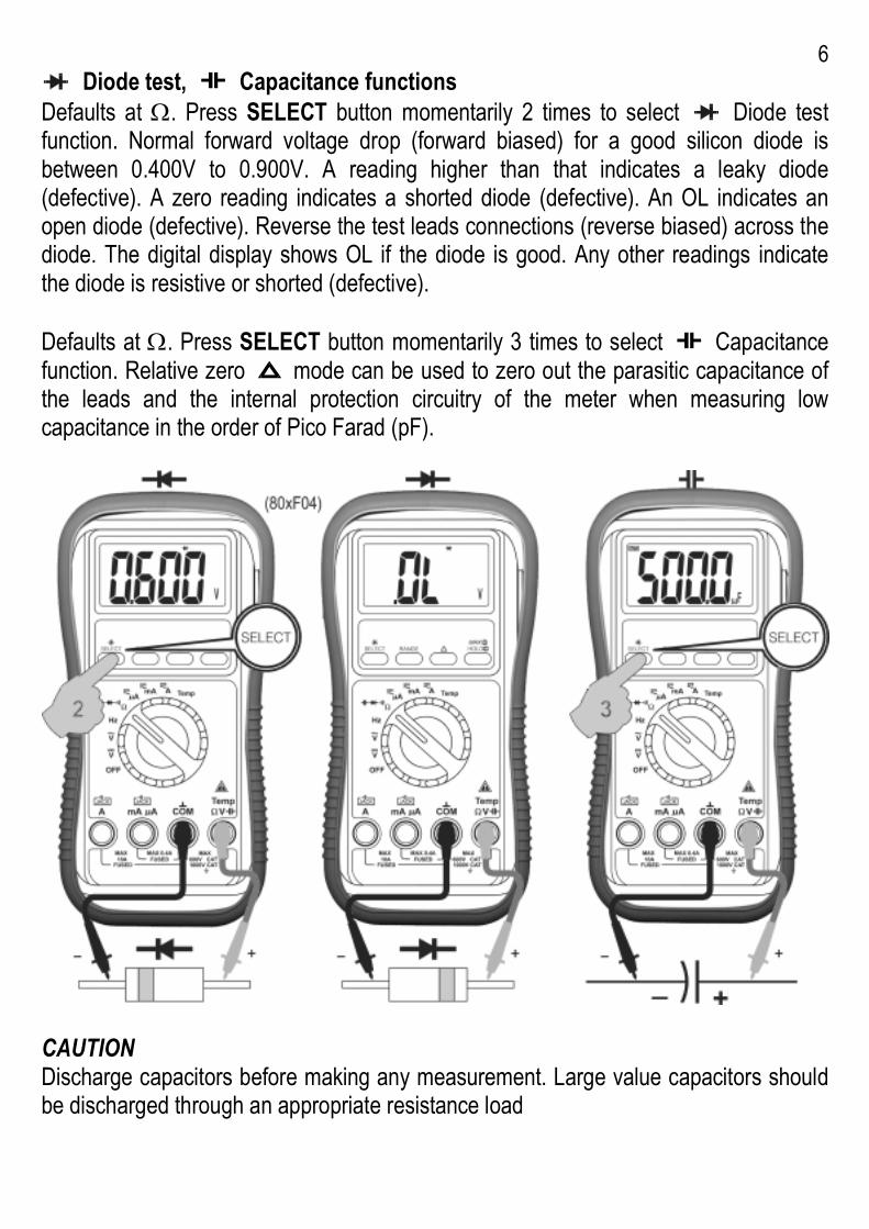
6 Diode test, Capacitance functions
Defaults at Ω. Press SELECT button momentarily 2 times to select Diode test function. Normal forward voltage drop (forward biased) for a good silicon diode is between 0.400V to 0.900V. A reading higher than that indicates a leaky diode (defective). A zero reading indicates a shorted diode (defective). An OL indicates an open diode (defective). Reverse the test leads connections (reverse biased) across the diode. The digital display shows OL if the diode is good. Any other readings indicate the diode is resistive or shorted (defective). Defaults at Ω. Press SELECT button momentarily 3 times to select Capacitance function. Relative zero mode can be used to zero out the parasitic capacitance of the leads and the internal protection circuitry of the meter when measuring low capacitance in the order of Pico Farad (pF).
CAUTION Discharge capacitors before making any measurement. Large value capacitors should be discharged through an appropriate resistance load
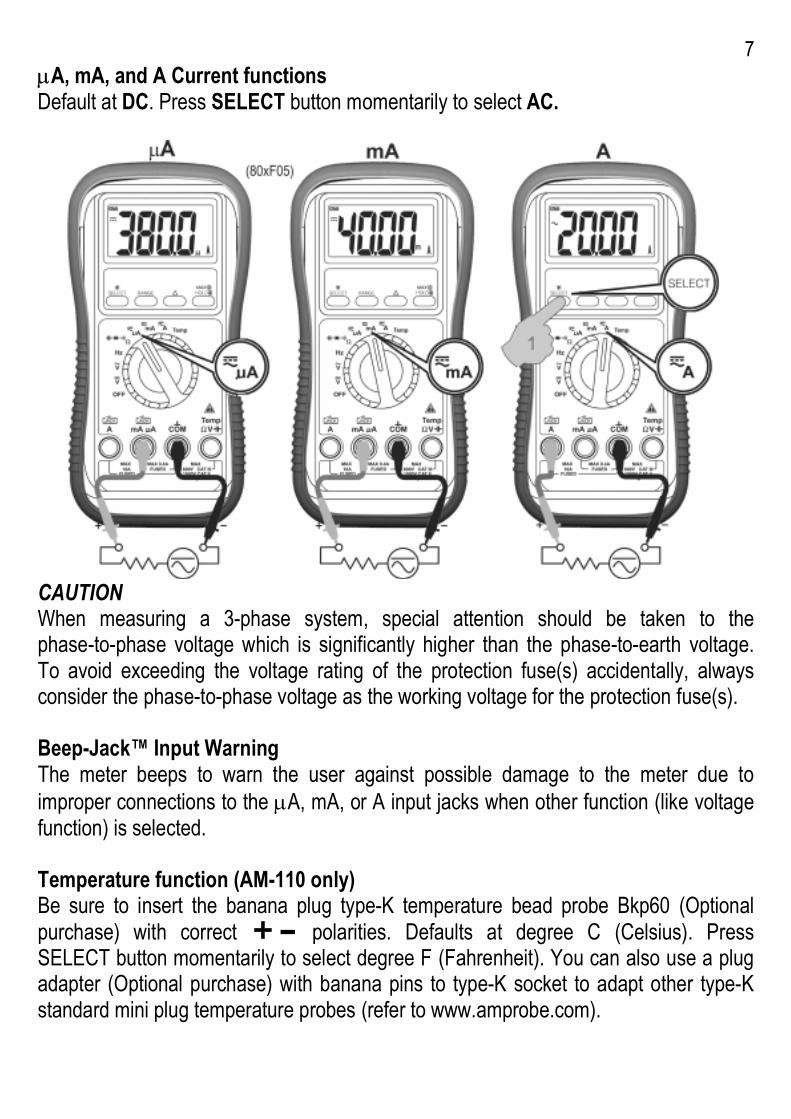
7 µA, mA, and A Current functions Default at DC. Press SELECT button momentarily to select AC.
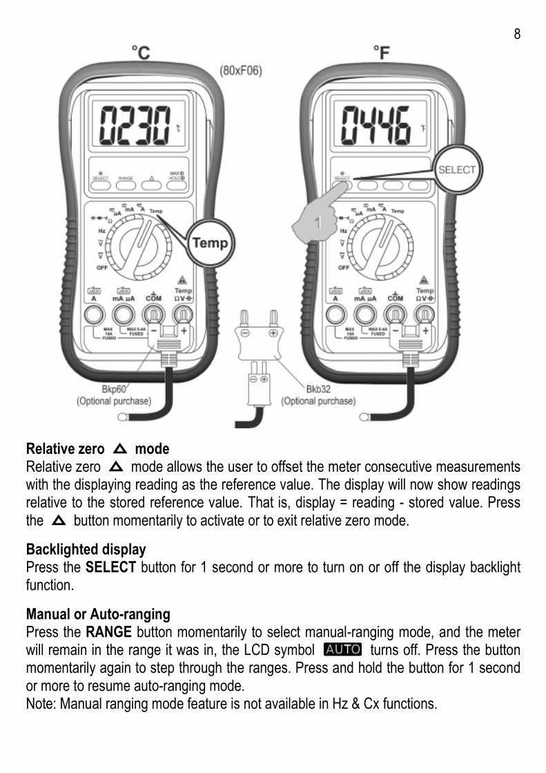
CAUTION When measuring a 3-phase system, special attention should be taken to the phase-to-phase voltage which is significantly higher than the phase-to-earth voltage. To avoid exceeding the voltage rating of the protection fuse(s) accidentally, always consider the phase-to-phase voltage as the working voltage for the protection fuse(s). Beep-Jack™ Input Warning The meter beeps to warn the user against possible damage to the meter due to improper connections to the µA, mA, or A input jacks when other function (like voltage function) is selected. Temperature function (AM-110 only) Be sure to insert the banana plug type-K temperature bead probe Bkp60 (Optional purchase) with correct polarities. Defaults at degree C (Celsius). Press SELECT button momentarily to select degree F (Fahrenheit). You can also use a plug adapter (Optional purchase) with banana pins to type-K socket to adapt other type-K standard mini plug temperature probes (refer to www.amprobe.com).
8
Relative zero mode Relative zero mode allows the user to offset the meter consecutive measurements with the displaying reading as the reference value. The display will now show readings relative to the stored reference value. That is, display = reading - stored value. Press the button momentarily to activate or to exit relative zero mode. Backlighted display Press the SELECT button for 1 second or more to turn on or off the display backlight function. Manual or Auto-ranging Press the RANGE button momentarily to select manual-ranging mode, and the meter will remain in the range it was in, the LCD symbol turns off. Press the button momentarily again to step through the ranges. Press and hold the button for 1 second or more to resume auto-ranging mode. Note: Manual ranging mode feature is not available in Hz & Cx functions.
9 HOLD The hold feature freezes the display for later view. Press the HOLD button momentarily to activate or to exit the hold feature. MAX The max feature compares and displays the measured maximum value as fast as 25ms in a single range, and with automatic up range capability. Press the MAX button for 1 second or more to activate or to exit the max feature in the voltage or current functions. Sleep Mode The meter will enter a low power consumption sleep mode automatically to extend battery life after approximately 30 minutes of no rotary-switch or push button operations. To wake up the meter from sleep mode, press any buttons momentarily or turn the rotary-switch to an adjacent position. Always set the rotary-switch to the OFF position manually when the meter is not in use. 5) MAINTENANCE WARNING To avoid electrical shock, disconnect the meter from any circuit, remove the test leads from the input jacks and turn OFF the meter before opening the case. Do not operate with open case. Cleaning and Storage Periodically wipe the case with a damp cloth and mild detergent; do not use abrasives or solvents. If the meter is not to be used for periods of longer than 60 days, remove the batteries and store them separately Trouble Shooting If the instrument fails to operate, check batteries and test leads etc., and replace as necessary. Double check operating procedure as described in this user’s manual. If the instrument voltage-resistance input terminal has subjected to high voltage transient (caused by lightning or switching surge to the system) by accident or abnormal conditions of operation, the series fusible resistors will be blown off (become high impedance) like fuses to protect the user and the instrument. Most measuring functions through this terminal will then be open circuit. The series fusible resistors and the spark gaps should then be replaced by qualified technician. Refer to the LIMITED WARRANTY section for obtaining warranty or repairing service.
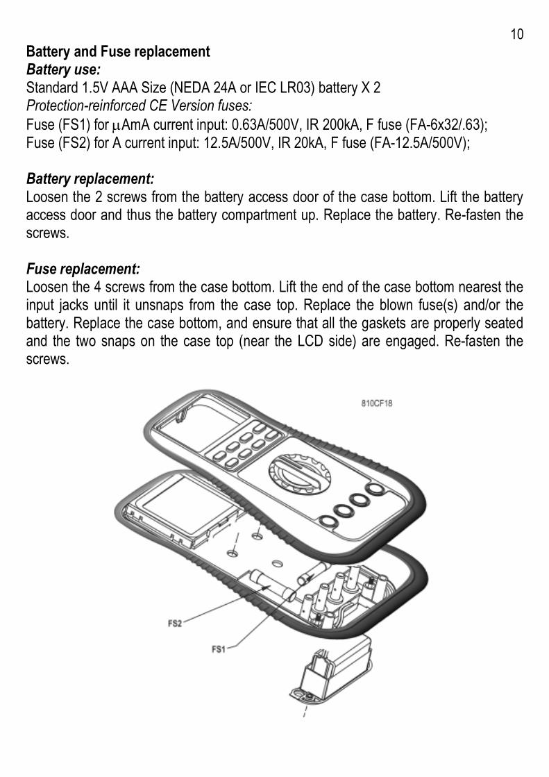
10 Battery and Fuse replacement Battery use: Standard 1.5V AAA Size (NEDA 24A or IEC LR03) battery X 2 Protection-reinforced CE Version fuses: Fuse (FS1) for µAmA current input: 0.63A/500V, IR 200kA, F fuse (FA-6x32/.63); Fuse (FS2) for A current input: 12.5A/500V, IR 20kA, F fuse (FA-12.5A/500V); Battery replacement: Loosen the 2 screws from the battery access door of the case bottom. Lift the battery access door and thus the battery compartment up. Replace the battery. Re-fasten the screws. Fuse replacement: Loosen the 4 screws from the case bottom. Lift the end of the case bottom nearest the input jacks until it unsnaps from the case top. Replace the blown fuse(s) and/or the battery. Replace the case bottom, and ensure that all the gaskets are properly seated and the two snaps on the case top (near the LCD side) are engaged. Re-fasten the screws.
11 6) Specifications General Specifications Display : 3-3/4 digits 4000 counts LCD display Polarity : Automatic Update Rate : 3 per second nominal Operating Temperature : 0°C to 40°C Relative Humidity : Maximum relative humidity 80% for temperature up to 31°C decreasing linearly to 50% relative humidity at 40°C Altitude: Operating below 2000m Pollution degree: 2 Storage Temperature: -20OC to 60OC, < 80% R.H. (with battery removed) Temperature Coefficient: nominal 0.15 x (specified accuracy)/OC @(0OC -18OC or 28OC -40OC), or otherwise specified Sensing: Average sensing for AM-100. True RMS for AM-105 TRMS & AM-110 TRMS Safety: The meter (all versions) is protected, against the users, by double insulation per CSA C22.2 No. 1010-1-92, EN61010-1(1995) and IEC61010-1(1995) to CAT II 1000V & CAT III 600V. Protection-reinforced CE Terminals (to COM) ratings: V : Category II 1000 Volts AC & DC, and Category III 600 Volts AC & DC. A / mAµA : Category III 500 Volts AC and 300 Volts DC. Overload Protections: Protection-reinforced CE: µA & mA : 0.63A/500V, IR200kA, F Fuse; A: 12.5A/500V, IR20kA, F Fuse; V: 1050Vrms, 1450Vpeak; Ω, & Others: 600VDC/VAC rms Transient protection: 6.5kV (1.2/50µs surge) Power Supply: 1.5V AAA Size (NEDA 24A or IEC LR03) battery X 2 Power Consumption: 3.2 mA typical Low Battery: Below approx. 2.4V E.M.C.: Meets EN61326(1997, 1998/A1), EN61000-4-2(1995), and EN61000-4-3(1996) In an RF field of 3V/m: Capacitance function is not specified AC 4.000V range: Total Accuracy = Specified Accuracy + 700 digits AC 400.0µA range: Total Accuracy = Specified Accuracy + 300 digits Other function ranges: Total Accuracy = Specified Accuracy + 40 digits Performance above 3V/m is not specified
12 Sleep Mode Timing: Idle for 30 minutes Sleep Mode Consumption: 300µA typical for AM100; 360µA typical for AM-105 TRMS & AM-110 TRMS Dimension: L193mm X W97mm X H46 Weight: 370 gm Special Features: 25ms Max Hold; Data Hold; Relative zero mode; Beep-jack™ input warning; Back-lighted display (AM-110 TRMS only) Accessories: Test leads (pair), batteries installed, user's manual Electrical Specifications Accuracy is ±(% reading digits + number of digits) or otherwise specified, at 23 OC ±5
OC & less than 75% R.H.
1) Models AM-105 TRMS & AM-110 TRMS True RMS accuracy of ACV & ACA is specified from 5 % (10% for AC400.0mV range) to 100 % of range, or otherwise specified. Maximum Crest Factor < 1.75 : 1 at full scale & < 3.5 : 1 at half scale, and with frequency components within the specified frequency bandwidth for non-sinusoidal waveforms DC Voltage RANGE Accuracy 400.0 mV 0.3% + 4d 4.000V, 40.00V, 400.0V
0.5% + 3d
1000V 1.0% + 4d NMRR: >50dB @ 50/60Hz CMRR: >120dB @ DC, 50/60Hz, Rs=1kΩ Input Impedance: 10MΩ, 30pF nominal (1000MΩ for 400.0mV range) Type-K Temperature (AM-110 TRMS) RANGE Accuracy* -20 OC TO 300 OC 2% + 3 OC -4 OF TO 572 OF 2% + 6 OF *Type-K thermocouple range & accuracy not included
AC Voltage RANGE Accuracy 1) 50Hz -- 500Hz 400.0mV* 4.0% + 5d 4.000V, 40.00V, 400.0V
1.5% + 5d
1000V 4.0% + 5d CMRR: >60dB @ DC to 60Hz, Rs=1kΩ Input Impedance: 10MΩ, 30pF nominal (1000MΩ for 400.0mV range) *Selection by RANGE button manually, and is specified from AC 10mV (AC 40mV for True RMS models AM-105 TRMS AM-110 TRMS) and up Max Hold (Voltage & Current) Specified accuracy ± 50 digits for changes > 25ms in duration
13 DC Current RANGE Accuracy Burden
Voltage 400.0µA 2.0% + 5d 0.15mV/µA 4000µA 1.2% + 3d 0.15mV/µA 40.00mA 2.0% + 5d 3.3mV/mA 400.0mA 1.2% + 3d 3.3mV/mA 4.000A 2.0% + 5d 0.03V/A 10.00A* 1.2% + 3d 0.03V/A *10A continuous, 20A for 30 second max with 5 minutes cool down interval AC Current RANGE Accuracy 1) Burden
Voltage 50Hz -- 500Hz 400.0µA 2.0% + 6d 0.15mV/µA 4000µA 1.5% + 4d 0.15mV/µA 40.00mA 2.0% + 6d 3.3mV/mA 400.0mA 1.7% + 4d 3.3mV/mA 4.000A 2.0% + 6d 0.03V/A 10.00A* 1.8% + 4d 0.03V/A *10A continuous, 20A for 30 second max with 5 minutes cool down interval Ohms RANGE Accuracy 400.0Ω 0.8% + 6d 4.000kΩ, 40.00kΩ, 400.0kΩ
0.6% + 4d
4.000MΩ 1.0% + 4d 40.00MΩ 2.0% + 4d Open Circuit Voltage : 0.4VDC typical Audible Continuity Tester Audible threshold : between 10Ω and 120Ω
Capacitance RANGE* Accuracy** 500.0nF, 5.000µF, 50.00µF, 500.0µF, 3000µF
3.5%*** + 6d
*Additional 50.00nF range accuracy is not specified **Accuracies with film capacitor or better ***Specified with battery voltage above 2.8V (approximately half full battery). Accuracy decreases gradually to 12% at low battery warning voltage of approximately 2.4V Hz Frequency RANGE* Accuracy** 50.00Hz, 500.0Hz, 5.000kHz, 50.00kHz, 500.0kHz, 1.000MHz
0.5%+4d
*Additional 5.000Hz range accuracy & sensitivity are not specified **Accuracy is specified at < 20VAC rms Input Signal: Square wave with duty cycle > 40% & < 70%; or Sine wave Vrms AC Sensitivity: 10Hz--20Hz : > Sine 0.9Vrms; 20Hz--500kHz: > 2.6Vp; or Sine 1.9Vrms; 500kHz--1MHz: > 4.2Vp; or Sine 3Vrms Update Rate: 2 per second nominal Diode Tester Open Circuit Voltage
Test Current (Typical)
< 1.6 VDC 0.25mA
LIMITED WARRANTY Congratulations! Your new instrument has been quality crafted according to quality standards and contains quality components and workmanship. It has been inspected for proper operation of all of its functions and tested by qualified factory technicians according to the long-established standards of our company. Your instrument has a limited warranty against defective materials and/or workmanship for one year from the date of purchase provided that, in the opinion of the factory, the instrument has not been tampered with or taken apart. Should your instrument fail due to defective materials, and/or workmanship during this one year period, a no charge repair or replacement will be made to the original purchaser. Please have your dated bill of sale, which must identify the instrument model number and serial number and call the number listed below:
Repair Department ATP – Amprobe, TIF, Promax Miramar, FL Phone: 954-499-5400
800-327-5060 Fax: 954-499-5454 Website: www.amprobe.com
Please obtain an RMA number before returning product for repair. Outside the U.S.A. the local representative will assist you. Above limited warranty covers repair and replacement of instrument only and no other obligation is stated or implied.
P/N: 7M1C-0671-0000