Embed Size (px)
Citation preview

Doc 4444-ATM/501 Amendment No. 1 15/11/12
AMENDMENT NO. 1
TO THE
PROCEDURES
FOR
AIR NAVIGATION SERVICES
AIR TRAFFIC MANAGEMENT FIFTEENTH EDITION — 2007
INTERNATIONAL CIVIL AVIATION ORGANIZATION

Checklist of Amendments to the PANS-ATM (Doc 4444), Fifteenth Edition
Date of applicability
Amendment No. 1 (Approved by the President of the Council of ICAO on behalf of the Council on 27 May 2008) Replacement pages (xv), 4-4 to 4-6, 11-10 and 11-11, A2-3 to A2-25, A3-2, A3-3, A3-5, A3-10, A3-12 to A3-15 and A3-20 to A3-47
15 November 2012 Amendment No. 2 (Approved by the President of the Council of ICAO on behalf of the Council on 1 June 2009)
19 November 2009
Amendment No. 3 (Approved by the President of the Council of ICAO on behalf of the Council on 12 October 2010)
18 November 2010
Transmittal note Amendment No. 1 to the Procedures for Air Navigation Services AIR TRAFFIC MANAGEMENT (Doc 4444) 1. Insert the following replacement pages in the PANS-ATM (Fifteenth Edition) to incorporate Amendment No. 1 which becomes applicable on 15 November 2012.
a) Page (xv) — Foreword b) Pages 4-4 to 4-6 — Chapter 4 c) Pages 11-10 and 11-11 — Chapter 11 d) Pages A2-3 to A2-25 — Appendix 2 e) Pages A3-2, A3-3, A3-5, — Appendix 3 A3-10, A3-12 to A3-15, A3-20 to A3-47
2. Record the entry of this amendment on page (ii).
4/11/11

�������
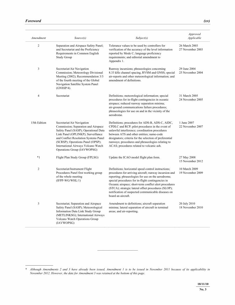
Foreword (xv)
22/11/07
Amendment Source(s) Subject(s) Approved Applicable
2 Separation and Airspace Safety Panel; and Secretariat and the Proficiency Requirements in Common English Study Group
Tolerance values to be used by controllers for verification of the accuracy of the level information reported by Mode C; language proficiency requirements; and editorial amendment to Appendix 1.
26 March 2003 27 November 2003
3 Secretariat/Air Navigation Commission; Meteorology Divisional Meeting (2002); Recommendation 3/3 of the fourth meeting of the Global Navigation Satellite System Panel (GNSSP/4).
Runway incursions; phraseologies concerning 8.33 kHz channel spacing, RVSM and GNSS; special air-reports and other meteorological information; and amendment of definitions.
29 June 2004 25 November 2004
4 Secretariat Definitions; meteorological information; special procedures for in-flight contingencies in oceanic airspace; reduced runway separation minima; air-ground communications failure procedures; phraseologies for use on and in the vicinity of the aerodrome.
31 March 2005 24 November 2005
15th Edition Secretariat/Air Navigation Commission; Separation and Airspace Safety Panel (SASP); Operational DataLink Panel (OPLINKP); Surveillance and Conflict Resolution Systems Panel (SCRSP); Operations Panel (OPSP); International Airways Volcano Watch Operations Group (IAVWOPSG)
Definitions; procedures for ADS-B, ADS-C, AIDC, CPDLC and RCP; pilot procedures in the event of unlawful interference; coordination procedures between ATS and other entities; name-code designators; criteria for the selection of preferential runways; procedures and phraseologies relating to ACAS; procedures related to volcanic ash.
1 June 2007 22 November 2007
*1 Flight Plan Study Group (FPLSG) Update the ICAO model flight plan form. 27 May 2008 15 November 2012
2 Secretariat/Instrument Flight Procedures Panel first working group of the whole meeting (IFPP-WG/WHL/1)
Definitions; horizontal speed control instructions; procedures for arriving aircraft; runway incursion and reporting; phraseologies for use on the aerodrome; special procedures for in-flight contingencies in Oceanic airspace; short-term conflict alert procedures (STCA); strategic lateral offset procedures (SLOP); notification of suspected communicable diseases on board an aircraft.
10 March 2009 19 November 2009
3 Secretariat; Separation and Airspace Safety Panel (SASP); Meteorological Information Data Link Study Group (METLINKSG); International AirwaysVolcano Watch Operations Group (IAVWOPSG)
Amendment to definitions; aircraft separation minima; lateral separation of aircraft in terminal areas; and air-reporting.
20 July 2010 18 November 2010
_____________________
* Although Amendments 2 and 3 have already been issued, Amendment 1 is to be issued in November 2011 because of its applicability in
November 2012. However, the date for Amendment 3 was retained at the bottom of this page.
18/11/10
No. 3

�������
Chapter 4. General Provisions for Air Traffic Services 4-3
22/11/07
b) when instrument meteorological conditions prevail at the aerodrome: 1) immediately after the aircraft is airborne, or 2) when the aircraft is at a prescribed point or level, as specified in letters of agreement or local instructions. Note.— See Note following 4.3.2.1.2.
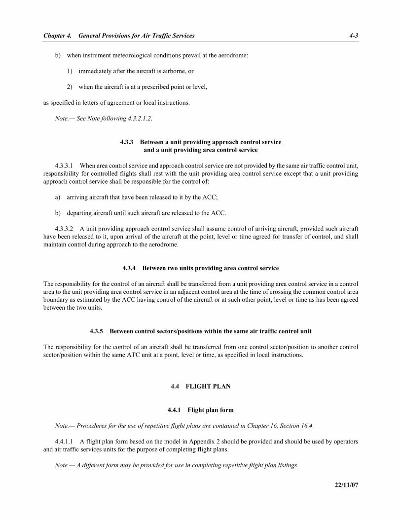
4.3.3 Between a unit providing approach control service and a unit providing area control service
4.3.3.1 When area control service and approach control service are not provided by the same air traffic control unit, responsibility for controlled flights shall rest with the unit providing area control service except that a unit providing approach control service shall be responsible for the control of: a) arriving aircraft that have been released to it by the ACC; b) departing aircraft until such aircraft are released to the ACC. 4.3.3.2 A unit providing approach control service shall assume control of arriving aircraft, provided such aircraft have been released to it, upon arrival of the aircraft at the point, level or time agreed for transfer of control, and shall maintain control during approach to the aerodrome.
4.3.4 Between two units providing area control service The responsibility for the control of an aircraft shall be transferred from a unit providing area control service in a control area to the unit providing area control service in an adjacent control area at the time of crossing the common control area boundary as estimated by the ACC having control of the aircraft or at such other point, level or time as has been agreed between the two units.
4.3.5 Between control sectors/positions within the same air traffic control unit The responsibility for the control of an aircraft shall be transferred from one control sector/position to another control sector/position within the same ATC unit at a point, level or time, as specified in local instructions.
4.4 FLIGHT PLAN
4.4.1 Flight plan form Note.— Procedures for the use of repetitive flight plans are contained in Chapter 16, Section 16.4. 4.4.1.1 A flight plan form based on the model in Appendix 2 should be provided and should be used by operators and air traffic services units for the purpose of completing flight plans. Note.— A different form may be provided for use in completing repetitive flight plan listings.
4-4 Air Traffic Management (PANS-ATM)
22/11/07
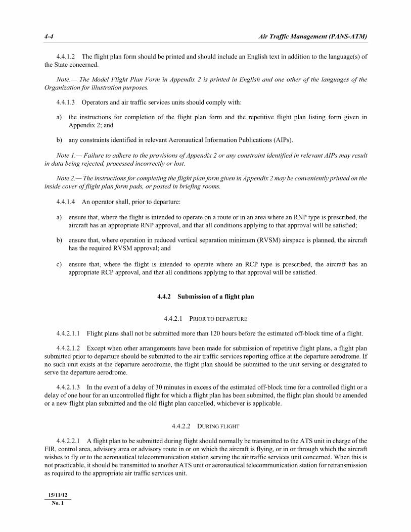
4.4.1.2 The flight plan form should be printed and should include an English text in addition to the language(s) of the State concerned. Note.— The Model Flight Plan Form in Appendix 2 is printed in English and one other of the languages of the Organization for illustration purposes. 4.4.1.3 Operators and air traffic services units should comply with: a) the instructions for completion of the flight plan form and the repetitive flight plan listing form given in
Appendix 2; and b) any constraints identified in relevant Aeronautical Information Publications (AIPs). Note 1.— Failure to adhere to the provisions of Appendix 2 or any constraint identified in relevant AIPs may result in data being rejected, processed incorrectly or lost. Note 2.— The instructions for completing the flight plan form given in Appendix 2 may be conveniently printed on the inside cover of flight plan form pads, or posted in briefing rooms. 4.4.1.4 An operator shall, prior to departure: a) ensure that, where the flight is intended to operate on a route or in an area where an RNP type is prescribed, the
aircraft has an appropriate RNP approval, and that all conditions applying to that approval will be satisfied; b) ensure that, where operation in reduced vertical separation minimum (RVSM) airspace is planned, the aircraft
has the required RVSM approval; and c) ensure that, where the flight is intended to operate where an RCP type is prescribed, the aircraft has an
appropriate RCP approval, and that all conditions applying to that approval will be satisfied.
4.4.2 Submission of a flight plan
4.4.2.1 PRIOR TO DEPARTURE 4.4.2.1.1 Flight plans shall not be submitted more than 120 hours before the estimated off-block time of a flight. 4.4.2.1.2 Except when other arrangements have been made for submission of repetitive flight plans, a flight plan submitted prior to departure should be submitted to the air traffic services reporting office at the departure aerodrome. If no such unit exists at the departure aerodrome, the flight plan should be submitted to the unit serving or designated to serve the departure aerodrome. 4.4.2.1.3 In the event of a delay of 30 minutes in excess of the estimated off-block time for a controlled flight or a delay of one hour for an uncontrolled flight for which a flight plan has been submitted, the flight plan should be amended or a new flight plan submitted and the old flight plan cancelled, whichever is applicable.
4.4.2.2 DURING FLIGHT 4.4.2.2.1 A flight plan to be submitted during flight should normally be transmitted to the ATS unit in charge of the FIR, control area, advisory area or advisory route in or on which the aircraft is flying, or in or through which the aircraft wishes to fly or to the aeronautical telecommunication station serving the air traffic services unit concerned. When this is not practicable, it should be transmitted to another ATS unit or aeronautical telecommunication station for retransmission as required to the appropriate air traffic services unit.
15/11/12 No. 1
Chapter 4. General Provisions for Air Traffic Services 4-5
22/11/07
4.4.2.2.2 Where relevant, such as in respect of ATC units serving high- or medium-density airspace, the appropriate ATS authority should prescribe conditions and/or limitations with respect to the submission of flight plans during flight to ATC units. Note.— If the flight plan is submitted for the purpose of obtaining air traffic control service, the aircraft is required to wait for an air traffic control clearance prior to proceeding under the conditions requiring compliance with air traffic control procedures. If the flight plan is submitted for the purpose of obtaining air traffic advisory service, the aircraft is required to wait for acknowledgment of receipt by the unit providing the service.
4.4.3 Acceptance of a flight plan The first ATS unit receiving a flight plan, or change thereto, shall: a) check it for compliance with the format and data conventions; b) check it for completeness and, to the extent possible, for accuracy; c) take action, if necessary, to make it acceptable to the air traffic services; and d) indicate acceptance of the flight plan or change thereto, to the originator.
4.5 AIR TRAFFIC CONTROL CLEARANCES
4.5.1 Scope and purpose 4.5.1.1 Clearances are issued solely for expediting and separating air traffic and are based on known traffic conditions which affect safety in aircraft operation. Such traffic conditions include not only aircraft in the air and on the manoeuvring area over which control is being exercised, but also any vehicular traffic or other obstructions not permanently installed on the manoeuvring area in use. 4.5.1.2 If an air traffic control clearance is not suitable to the pilot-in-command of an aircraft, the flight crew may request and, if practicable, obtain an amended clearance. 4.5.1.3 The issuance of air traffic control clearances by air traffic control units constitutes authority for an aircraft to proceed only in so far as known air traffic is concerned. ATC clearances do not constitute authority to violate any applicable regulations for promoting the safety of flight operations or for any other purpose; neither do clearances relieve a pilot-in-command of any responsibility whatsoever in connection with a possible violation of applicable rules and regulations. 4.5.1.4 ATC units shall issue such ATC clearances as are necessary to prevent collisions and to expedite and maintain an orderly flow of air traffic. 4.5.1.5 ATC clearances must be issued early enough to ensure that they are transmitted to the aircraft in sufficient time for it to comply with them.
4.5.2 Aircraft subject to ATC for part of flight 4.5.2.1 When a flight plan specifies that the initial portion of a flight will be uncontrolled, and that the subsequent portion of the flight will be subject to ATC, the aircraft shall be advised to obtain its clearance from the ATC unit in whose area controlled flight will be commenced.
15/11/12 No. 1
4-6 Air Traffic Management (PANS-ATM)
22/11/07
4.5.2.2 When a flight plan specifies that the first portion of a flight will be subject to ATC, and that the subsequent portion will be uncontrolled, the aircraft shall normally be cleared to the point at which the controlled flight terminates.
4.5.3 Flights through intermediate stops 4.5.3.1 When an aircraft files, at the departure aerodrome, flight plans for the various stages of flight through intermediate stops, the initial clearance limit will be the first destination aerodrome and new clearances shall be issued for each subsequent portion of flight. 4.5.3.2 The flight plan for the second stage, and each subsequent stage, of a flight through intermediate stops will become active for ATS and search and rescue (SAR) purposes only when the appropriate ATS unit has received notification that the aircraft has departed from the relevant departure aerodrome, except as provided for in 4.5.3.3. 4.5.3.3 By prior arrangement between ATC units and the operators, aircraft operating on an established schedule may, if the proposed route of flight is through more than one control area, be cleared through intermediate stops within other control areas but only after coordination between the ACCs concerned.
4.5.4 Contents of clearances 4.5.4.1 Clearances shall contain positive and concise data and shall, as far as practicable, be phrased in a standard manner. 4.5.4.2 Clearances shall, except as provided for in Chapter 6, Section 6.3.2, concerning standard departure clearances, contain the items specified in Chapter 11, 11.4.2.6.2.1.
4.5.5 Departing aircraft ACCs shall, except where procedures providing for the use of standard departure clearances have been implemented, forward a clearance to approach control units or aerodrome control towers with the least possible delay after receipt of request made by these units, or prior to such request if practicable.
4.5.6 En-route aircraft
4.5.6.1 GENERAL 4.5.6.1.1 An ATC unit may request an adjacent ATC unit to clear aircraft to a specified point during a specified period. 4.5.6.1.2 After the initial clearance has been issued to an aircraft at the point of departure, it will be the responsibility of the appropriate ATC unit to issue an amended clearance whenever necessary and to issue traffic information, if required. 4.5.6.1.3 When so requested by the flight crew, an aircraft shall be cleared for cruise climb whenever traffic conditions and coordination procedures permit. Such clearance shall be for cruise climb either above a specified level or between specified levels.
4.5.6.2 CLEARANCES RELATING TO SUPERSONIC FLIGHT 4.5.6.2.1 Aircraft intending supersonic flight shall, whenever practicable, be cleared for the transonic acceleration phase prior to departure. 4.5.6.2.2 During the transonic and supersonic phases of a flight, amendments to the clearance should be kept to a minimum and must take due account of the operational limitations of the aircraft in these flight phases.
15/11/12 No. 1
Chapter 11. Air Traffic Services Messages 11-9
22/11/07
11.4.1.3.1 When an ATS unit is aware that an aircraft in its area is experiencing radiocommunication failure, an RCF message shall be transmitted to all subsequent ATS units along the route of flight which have already received basic flight plan data (FPL or RPL) and to the aerodrome control tower at the destination aerodrome, if basic flight plan data has been previously sent. 11.4.1.3.2 If the next ATS unit has not yet received basic flight plan data because it would receive a current flight plan message in the coordination procedure, then an RCF message and a current flight plan (CPL) message shall be transmitted to this ATS unit. In turn, this ATS unit shall transmit an RCF message and a CPL message to the next ATS unit.
11.4.1.4 FREE TEXT EMERGENCY MESSAGES (AIDC, APPENDIX 6 REFERS) 11.4.1.4.1 Whenever operational information needs to be transmitted concerning an aircraft known or believed to be in a state of emergency and the information cannot be formatted to comply with any other AIDC message type, a free text emergency message shall be sent. 11.4.1.4.2 The following are some examples of circumstances which could justify the use of a free text emergency message: a) reports of emergency calls or emergency locator transmission reports; b) messages concerning unlawful interference or bomb warnings; c) messages concerning serious illness or disturbance among passengers; d) sudden alteration in flight profile due to technical or navigational failure; and e) communication failure.
11.4.2 Movement and control messages
11.4.2.1 GENERAL
Messages concerning the intended or actual movement of aircraft shall be based on the latest information furnished to ATS units by the pilot, the operator or its designated representative, or derived from an ATS surveillance system.
11.4.2.2 MOVEMENT MESSAGES 11.4.2.2.1 Movement messages comprise: — filed flight plan messages (11.4.2.2.2) — delay messages (11.4.2.2.3) — modification messages (11.4.2.2.4) — flight plan cancellation messages (11.4.2.2.5) — departure messages (11.4.2.2.6) — arrival messages (11.4.2.2.7). 11.4.2.2.2 FILED FLIGHT PLAN (FPL) MESSAGES Note.— Instructions for the transmission of an FPL message are contained in Appendix 2.
11-10 Air Traffic Management (PANS-ATM)
22/11/07
11.4.2.2.2.1 Unless repetitive flight plan procedures are being applied or current flight plan messages are being employed, filed flight plan messages shall be transmitted for all flights for which a flight plan has been submitted with the object of being provided with air traffic control service, flight information service or alerting service along part or the whole of the route of flight. 11.4.2.2.2.2 A filed flight plan message shall be originated and addressed as follows by the ATS unit serving the departure aerodrome or, when applicable, by the ATS unit receiving a flight plan from an aircraft in flight: a) an FPL message shall be sent to the ACC or flight information centre serving the control area or FIR within
which the departure aerodrome is situated; b) unless basic flight plan data are already available as a result of arrangements made for repetitive flight plans, an
FPL message shall be sent to all centres in charge of each FIR or upper FIR along the route which are unable to process current data. In addition, an FPL message shall be sent to the aerodrome control tower at the destination aerodrome. If so required, an FPL message shall also be sent to flow management centres responsible for ATS units along the route;
c) when a potential re-clearance in flight (RIF) request is indicated in the flight plan, the FPL message shall be sent
to the additional centres concerned and to the aerodrome control tower of the revised destination aerodrome; d) where it has been agreed to use CPL messages but where information is required for early planning of traffic
flow, an FPL message shall be transmitted to the ACCs concerned; e) for a flight along routes where flight information service and alerting service only are provided, an FPL message
shall be addressed to the centre in charge of each FIR or upper FIR along the route and to the aerodrome control tower at the destination aerodrome.
11.4.2.2.2.3 In the case of a flight through intermediate stops, where flight plans for each stage of the flight are filed at the first departure aerodrome, the following procedure shall be applied: a) the air traffic services reporting office at the first departure aerodrome shall: 1) transmit an FPL message for the first stage of flight in accordance with 11.4.2.2.2.2; 2) transmit a separate FPL message for each subsequent stage of flight, addressed to the air traffic services
reporting office at the appropriate subsequent departure aerodrome; b) the air traffic services reporting office at each subsequent departure aerodrome shall take action on receipt of the
FPL message as if the flight plan has been filed locally. 11.4.2.2.2.4 When so required by agreement between the appropriate ATS authorities to assist in the identification of flights and thereby eliminate or reduce the need for interceptions in the event of deviations from assigned track, FPL messages for flights along specified routes or portions of routes in close proximity to FIR boundaries shall also be addressed to the centres in charge of each FIR or upper FIR adjacent to such routes or portions of routes. 11.4.2.2.2.5 FPL messages should be transmitted immediately after the filing of the flight plan. If a flight plan is filed more than 24 hours in advance of the estimated off-block time of the flight to which it refers, the date of the flight departure shall be inserted in Item 18 of the flight plan.
15/11/12 No. 1
Chapter 11. Air Traffic Services Messages 11-11
22/11/07
11.4.2.2.3 DELAY (DLA) MESSAGES 11.4.2.2.3.1 A DLA message shall be transmitted when the departure of an aircraft, for which basic flight plan data (FPL or RPL) has been sent, is delayed by more than 30 minutes after the estimated off-block time contained in the basic flight plan data. 11.4.2.2.3.2 The DLA message shall be transmitted by the ATS unit serving the departure aerodrome to all recipients of basic flight plan data. Note.— See 11.4.2.3.4 concerning notification of a delayed departure of an aircraft for which a CPL message has been transmitted. 11.4.2.2.4 MODIFICATION (CHG) MESSAGES A CHG message shall be transmitted when any change is to be made to basic flight plan data contained in previously transmitted FPL or RPL data. The CHG message shall be sent to those recipients of basic flight plan data which are affected by the change. Relevant revised basic flight plan data shall be provided to such affected entities not previously having received this. Note.— See 11.4.2.3.4 concerning notification of a change to coordination data contained in a previously transmitted current flight plan or estimate message. 11.4.2.2.5 FLIGHT PLAN CANCELLATION (CNL) MESSAGES A flight plan cancellation (CNL) message shall be transmitted when a flight, for which basic flight plan data has been previously distributed, has been cancelled. The ATS unit serving the departure aerodrome shall transmit the CNL message to ATS units which have received basic flight plan data. 11.4.2.2.6 DEPARTURE (DEP) MESSAGES 11.4.2.2.6.1 Unless otherwise prescribed on the basis of regional air navigation agreements, a DEP message shall be transmitted immediately after the departure of an aircraft for which basic flight plan data have been previously distributed. 11.4.2.2.6.2 The DEP message shall be transmitted by the ATS unit serving the departure aerodrome to all recipients of basic flight plan data. Note.— See 11.4.2.3.4 concerning notification of the departure of an aircraft for which a CPL message has been transmitted. 11.4.2.2.7 ARRIVAL (ARR) MESSAGES 11.4.2.2.7.1 When an arrival report is received by the ATS unit serving the arrival aerodrome, this unit shall transmit an ARR message: a) for a landing at the destination aerodrome: 1) to the ACC or flight information centre in whose area the arrival aerodrome is located, if required by that
unit; and
15/11/12 No. 1
11-12 Air Traffic Management (PANS-ATM)
22/11/07
2) to the ATS unit, at the departure aerodrome, which originated the flight plan message, if that message included a request for an ARR message;
b) for a landing at an alternate or other aerodrome: 1) to the ACC or flight information centre in whose area the arrival aerodrome is located; and 2) to the aerodrome control tower at the destination aerodrome; and 3) to the air traffic services reporting office at the departure aerodrome; and 4) to the ACC or flight information centre in charge of each FIR or upper FIR through which the aircraft would
have passed according to the flight plan, had it not diverted. 11.4.2.2.7.2 When a controlled flight which has experienced failure of two-way communication has landed, the aerodrome control tower at the arrival aerodrome shall transmit an ARR message: a) for a landing at the destination aerodrome: 1) to all ATS units concerned with the flight during the period of the communication failure; and 2) to all other ATS units which may have been alerted; b) for a landing at an aerodrome other than the destination aerodrome: to the ATS unit serving the destination aerodrome; this unit shall then transmit an ARR message to other ATS
units concerned or alerted as in a) above.
11.4.2.3 COORDINATION MESSAGES (APPENDIX 3 REFERS) Note.— The provisions governing coordination are contained in Chapter 10. Phraseology to be used in voice communication is contained in Chapter 12. See paragraph 11.4.2.5 below for the provisions governing AIDC messages, as prescribed in Appendix 6. 11.4.2.3.1 Coordination messages comprise: — current flight plan messages (11.4.2.3.2) — estimate messages (11.4.2.3.3) — coordination messages (11.4.2.3.4) — acceptance messages (11.4.2.3.5) — logical acknowledgement messages (11.4.2.3.6). 11.4.2.3.2 CURRENT FLIGHT PLAN (CPL) MESSAGES 11.4.2.3.2.1 Unless basic flight plan data have already been distributed (FPL or RPL) which will be supplemented by coordination data in the estimate message, a CPL message shall be transmitted by each ACC to the next ACC and from the last ACC to the aerodrome control tower at the destination aerodrome, for each controlled flight, and for each flight provided with air traffic advisory service along routes or portions of routes where it has been determined by the appropriate ATS authority that adequate point-to-point communications exist and that conditions are otherwise suitable for forwarding current flight plan information.
Appendix 2 A2-3
22/11/07
2. Instructions for the completion of the flight plan form
2.1 General Adhere closely to the prescribed formats and manner of specifying data. Commence inserting data in the first space provided. Where excess space is available, leave unused spaces blank. Insert all clock times in 4 figures UTC. Insert all estimated elapsed times in 4 figures (hours and minutes). Shaded area preceding Item 3 — to be completed by ATS and COM services, unless the responsibility for originating flight plan messages has been delegated. Note.— The term “aerodrome” where used in the flight plan is intended to cover also sites other than aerodromes which may be used by certain types of aircraft, e.g. helicopters or balloons.
2.2 Instructions for insertion of ATS data Complete Items 7 to 18 as indicated hereunder. Complete also Item 19 as indicated hereunder, when so required by the appropriate ATS authority or when otherwise deemed necessary. Note 1.— Item numbers on the form are not consecutive, as they correspond to Field Type numbers in ATS messages. Note 2.— Air traffic services data systems may impose communications or processing constraints on information in filed flight plans. Possible constraints may, for example, be limits with regard to item length, number of elements in the route item or total flight plan length. Significant constraints are documented in the relevant Aeronautical Information Publication.
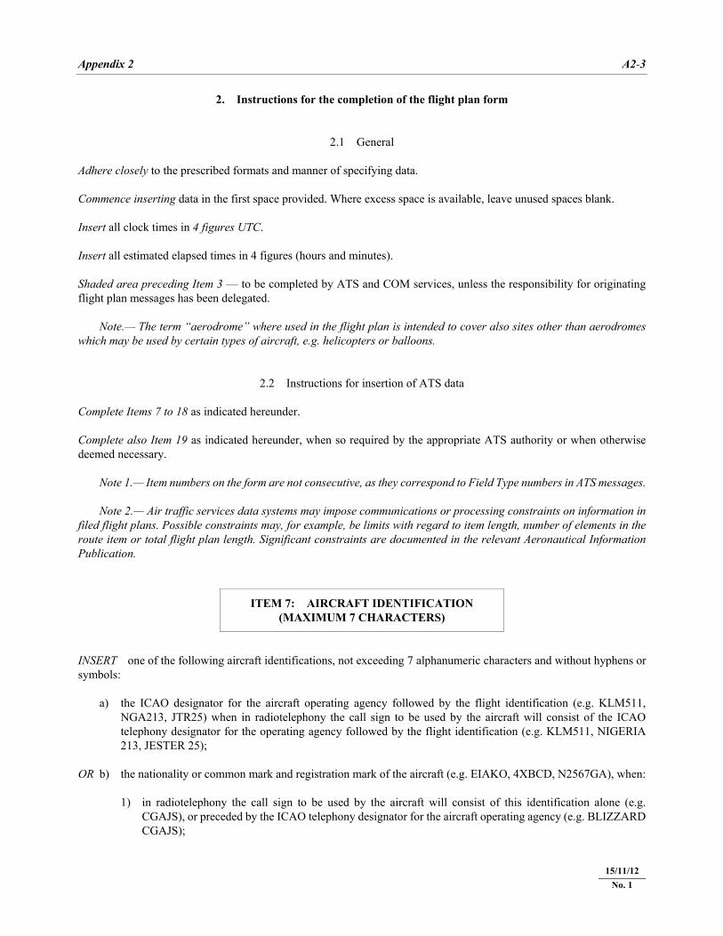
ITEM 7: AIRCRAFT IDENTIFICATION (MAXIMUM 7 CHARACTERS)
INSERT one of the following aircraft identifications, not exceeding 7 alphanumeric characters and without hyphens or symbols: a) the ICAO designator for the aircraft operating agency followed by the flight identification (e.g. KLM511,
NGA213, JTR25) when in radiotelephony the call sign to be used by the aircraft will consist of the ICAO telephony designator for the operating agency followed by the flight identification (e.g. KLM511, NIGERIA 213, JESTER 25);
OR b) the nationality or common mark and registration mark of the aircraft (e.g. EIAKO, 4XBCD, N2567GA), when: 1) in radiotelephony the call sign to be used by the aircraft will consist of this identification alone (e.g.
CGAJS), or preceded by the ICAO telephony designator for the aircraft operating agency (e.g. BLIZZARD CGAJS);
15/11/12 No. 1
A2-4 Air Traffic Management (PANS-ATM)
22/11/07
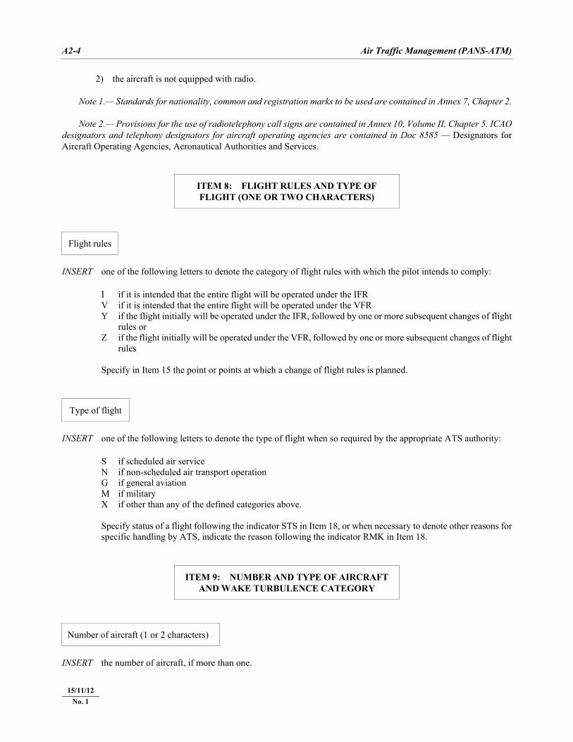
2) the aircraft is not equipped with radio. Note 1.— Standards for nationality, common and registration marks to be used are contained in Annex 7, Chapter 2. Note 2.— Provisions for the use of radiotelephony call signs are contained in Annex 10, Volume II, Chapter 5. ICAO designators and telephony designators for aircraft operating agencies are contained in Doc 8585 — Designators for Aircraft Operating Agencies, Aeronautical Authorities and Services.
ITEM 8: FLIGHT RULES AND TYPE OF FLIGHT (ONE OR TWO CHARACTERS)
Flight rules
INSERT one of the following letters to denote the category of flight rules with which the pilot intends to comply: I if it is intended that the entire flight will be operated under the IFR V if it is intended that the entire flight will be operated under the VFR Y if the flight initially will be operated under the IFR, followed by one or more subsequent changes of flight
rules or Z if the flight initially will be operated under the VFR, followed by one or more subsequent changes of flight
rules Specify in Item 15 the point or points at which a change of flight rules is planned.
Type of flight
INSERT one of the following letters to denote the type of flight when so required by the appropriate ATS authority: S if scheduled air service N if non-scheduled air transport operation G if general aviation M if military X if other than any of the defined categories above. Specify status of a flight following the indicator STS in Item 18, or when necessary to denote other reasons for
specific handling by ATS, indicate the reason following the indicator RMK in Item 18.
ITEM 9: NUMBER AND TYPE OF AIRCRAFT AND WAKE TURBULENCE CATEGORY
Number of aircraft (1 or 2 characters)
INSERT the number of aircraft, if more than one.
15/11/12 No. 1
Appendix 2 A2-5
22/11/07
Type of aircraft (2 to 4 characters)
INSERT the appropriate designator as specified in ICAO Doc 8643, Aircraft Type Designators, OR, if no such designator has been assigned, or in case of formation flights comprising more than one type, INSERT ZZZZ, and SPECIFY in Item 18, the (numbers and) type(s) of aircraft preceded by TYP/ .
Wake turbulence category (1 character)
INSERT an oblique stroke followed by one of the following letters to indicate the wake turbulence category of the aircraft: H — HEAVY, to indicate an aircraft type with a maximum certificated take-off mass of 136 000 kg or more; M — MEDIUM, to indicate an aircraft type with a maximum certificated take-off mass of less than
136 000 kg but more than 7 000 kg; L — LIGHT, to indicate an aircraft type with a maximum certificated take-off mass of 7 000 kg or less.
ITEM 10: EQUIPMENT AND CAPABILITIES
Capabilities comprise the following elements: a) presence of relevant serviceable equipment on board the aircraft; b) equipment and capabilities commensurate with flight crew qualifications; and c) where applicable, authorization from the appropriate authority.
Radiocommunication, navigation and approach aid equipment and capabilities
INSERT one letter as follows: N if no COM/NAV/approach aid equipment for the route to be flown is carried, or the equipment is unserviceable, OR S if standard COM/NAV/approach aid equipment for the route to be flown is carried and serviceable
(see Note 1), AND/OR INSERT one or more of the following letters to indicate the serviceable COM/NAV/approach aid equipment and capabilities
available:
15/11/12 No. 1
A2-6 Air Traffic Management (PANS-ATM)
22/11/07
A GBAS landing system B LPV (APV with SBAS)C LORAN C D DME E1 FMC WPR ACARS E2 D-FIS ACARS E3 PDC ACARS F ADF G GNSS (See Note 2) H HF RTF I Inertial Navigation J1 CPDLC ATN VDL Mode 2 (See Note 3) J2 CPDLC FANS 1/A HFDL J3 CPDLC FANS 1/A VDL Mode 4 J4 CPDLC FANS 1/A VDL Mode 2 J5 CPDLC FANS 1/A SATCOM (INMARSAT)
J6 CPDLC FANS 1/A SATCOM (MTSAT) J7 CPDLC FANS 1/A SATCOM (Iridium) K MLS L ILS M1 ATC RTF SATCOM (INMARSAT) M2 ATC RTF (MTSAT) M3 ATC RTF (Iridium) O VOR P1–P9 Reserved for RCP R PBN approved (See Note 4) T TACAN U UHF RTF V VHF RTF W RVSM approved X MNPS approved Y VHF with 8.33 kHz channel spacing capability Z Other equipment carried or other capabilities (See Note 5)
Any alphanumeric characters not indicated above are reserved. Note 1.— If the letter S is used, standard equipment is considered to be VHF RTF, VOR and ILS, unless another combination is prescribed by the appropriate ATS authority. Note 2.— If the letter G is used, the types of external GNSS augmentation, if any, are specified in Item 18 following the indicator NAV/ and separated by a space. Note 3.— See RTCA/EUROCAE Interoperability Requirements Standard for ATN Baseline 1 (ATN B1 INTEROP Standard – DO-280B/ED-110B) for data link services air traffic control clearance and information/air traffic control communications management/air traffic control microphone check. Note 4.— If the letter R is used, the performance-based navigation levels that can be met are specified in Item 18 following the indicator PBN/. Guidance material on the application of performance-based navigation to a specific route segment, route or area is contained in the Performance-based Navigation (PBN) Manual (Doc 9613). Note 5.— If the letter Z is used, specify in Item 18 the other equipment carried or other capabilities, preceded by COM/ , NAV/ and/or DAT, as appropriate. Note 6.— Information on navigation capability is provided to ATC for clearance and routing purposes.
Surveillance equipment and capabilities
INSERT N if no surveillance equipment for the route to be flown is carried, or the equipment is unserviceable,
15/11/12 No. 1
Appendix 2 A2-7
22/11/07
OR INSERT one or more of the following descriptors, to a maximum of 20 characters, to describe the serviceable
surveillance equipment and/or capabilities on board: SSR Modes A and C A Transponder — Mode A (4 digits — 4 096 codes) C Transponder — Mode A (4 digits — 4 096 codes) and Mode C SSR Mode S E Transponder — Mode S, including aircraft identification, pressure-altitude and extended squitter (ADS-B)
capability H Transponder — Mode S, including aircraft identification, pressure-altitude and enhanced surveillance
capability I Transponder — Mode S, including aircraft identification, but no pressure-altitude capability L Transponder — Mode S, including aircraft identification, pressure-altitude, extended squitter (ADS-B) and
enhanced surveillance capability P Transponder — Mode S, including pressure-altitude, but no aircraft identification capability S Transponder — Mode S, including both pressure altitude and aircraft identification capability X Transponder — Mode S with neither aircraft identification nor pressure-altitude capability Note.— Enhanced surveillance capability is the ability of the aircraft to down-link aircraft derived data via a Mode S transponder. ADS-B B1 ADS-B with dedicated 1 090 MHz ADS-B “out” capability B2 ADS-B with dedicated 1 090 MHz ADS-B “out” and “in” capability U1 ADS-B “out” capability using UAT U2 ADS-B “out” and “in” capability using UAT V1 ADS-B “out” capability using VDL Mode 4 V2 ADS-B “out” and “in” capability using VDL Mode 4 ADS-C D1 ADS-C with FANS 1/A capabilities G1 ADS-C with ATN capabilities Alphanumeric characters not indicated above are reserved. Example: ADE3RV/HB2U2V2G1 Note.— Additional surveillance application should be listed in Item 18 following the indicator SUR/ .
ITEM 13: DEPARTURE AERODROME AND TIME (8 CHARACTERS)
INSERT the ICAO four-letter location indicator of the departure aerodrome as specified in Doc 7910, Location
Indicators,
15/11/12 No. 1
A2-8 Air Traffic Management (PANS-ATM)
22/11/07
OR, if no location indicator has been assigned, INSERT ZZZZ and SPECIFY, in Item 18, the name and location of the aerodrome preceded by DEP/ , OR, the first point of the route or the marker radio beacon preceded by DEP/…, if the aircraft has not taken off from
the aerodrome, OR, if the flight plan is received from an aircraft in flight, INSERT AFIL, and SPECIFY, in Item 18, the ICAO four-letter location indicator of the location of the ATS unit from
which supplementary flight plan data can be obtained, preceded by DEP/ . THEN, WITHOUT A SPACE, INSERT for a flight plan submitted before departure, the estimated off-block time (EOBT), OR, for a flight plan received from an aircraft in flight, the actual or estimated time over the first point of the route
to which the flight plan applies.
ITEM 15: ROUTE
INSERT the first cruising speed as in (a) and the first cruising level as in (b), without a space between them. THEN, following the arrow, INSERT the route description as in (c).
(a) Cruising speed (maximum 5 characters)
INSERT the True airspeed for the first or the whole cruising portion of the flight, in terms of: Kilometres per hour, expressed as K followed by 4 figures (e.g. K0830), or Knots, expressed as N followed by 4 figures (e.g. N0485), or True Mach number, when so prescribed by the appropriate ATS authority, to the nearest hundredth of unit Mach,
expressed as M followed by 3 figures (e.g. M082).
(b) Cruising level (maximum 5 characters)
INSERT the planned cruising level for the first or the whole portion of the route to be flown, in terms of: Flight level, expressed as F followed by 3 figures (e.g. F085; F330), or *Standard metric level in tens of metres, expressed as S followed by 4 figures (e.g. S1130), or Altitude in hundreds of feet, expressed as A followed by 3 figures (e.g. A045; A100), or
* When so prescribed by the appropriate ATS authorities.
15/11/12 No. 1
Appendix 2 A2-9
22/11/07
Altitude in tens of metres, expressed as M followed by 4 figures (e.g. M0840), or for uncontrolled VFR flights, the letters VFR.
(c) Route (including changes of speed, level and/or flight rules)
Flights along designated ATS routes INSERT, if the departure aerodrome is located on or connected to the ATS route, the designator of the first ATS route, OR, if the departure aerodrome is not on or connected to the ATS route, the letters DCT followed by the point of
joining the first ATS route, followed by the designator of the ATS route. THEN INSERT each point at which either a change of speed and/or level is planned to commence, or a change of ATS route,
and/or a change of flight rules is planned, Note.— When a transition is planned between a lower and upper ATS route and the routes are oriented in the same direction, the point of transition need not be inserted. FOLLOWED IN EACH CASE by the designator of the next ATS route segment, even if the same as the previous one, OR by DCT, if the flight to the next point will be outside a designated route, unless both points are defined by
geographical coordinates. Flights outside designated ATS routes INSERT points normally not more than 30 minutes flying time or 370 km (200 NM) apart, including each point at which
a change of speed or level, a change of track, or a change of flight rules is planned. OR, when required by appropriate ATS authority(ies), DEFINE the track of flights operating predominantly in an east-west direction between 70°N and 70°S by reference to
significant points formed by the intersections of half or whole degrees of latitude with meridians spaced at intervals of 10 degrees of longitude. For flights operating in areas outside those latitudes the tracks shall be defined by significant points formed by the intersection of parallels of latitude with meridians normally spaced at 20 degrees of longitude. The distance between significant points shall, as far as possible, not exceed one hour’s flight time. Additional significant points shall be established as deemed necessary.
For flights operating predominantly in a north-south direction, define tracks by reference to significant points
formed by the intersection of whole degrees of longitude with specified parallels of latitude which are spaced at 5 degrees.
INSERT DCT between successive points unless both points are defined by geographical coordinates or by bearing and
distance. USE ONLY the conventions in (1) to (5) below and SEPARATE each sub-item by a space.
15/11/12 No. 1
A2-10 Air Traffic Management (PANS-ATM)
22/11/07
(1) ATS route (2 to 7 characters)
The coded designator assigned to the route or route segment including, where appropriate, the coded designator assigned to the standard departure or arrival route (e.g. BCN1, Bl, R14, UB10, KODAP2A). Note.— Provisions for the application of route designators are contained in Annex 11, Appendix 1.
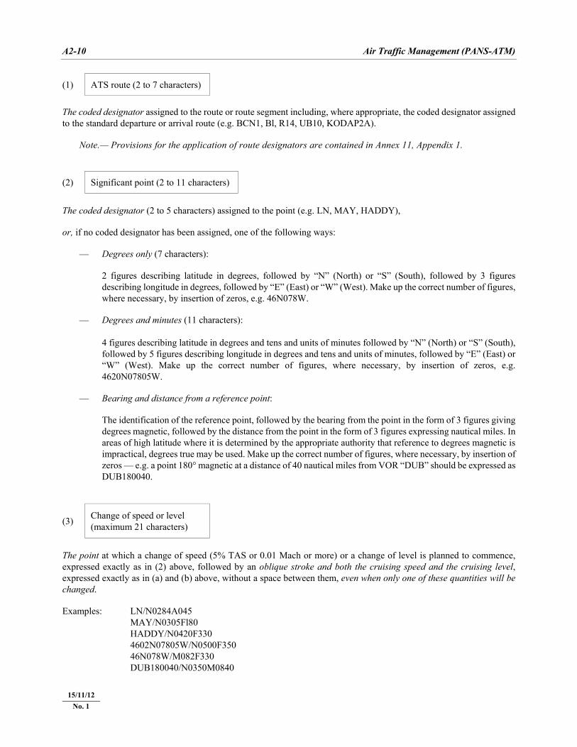
(2) Significant point (2 to 11 characters)
The coded designator (2 to 5 characters) assigned to the point (e.g. LN, MAY, HADDY), or, if no coded designator has been assigned, one of the following ways: — Degrees only (7 characters): 2 figures describing latitude in degrees, followed by “N” (North) or “S” (South), followed by 3 figures
describing longitude in degrees, followed by “E” (East) or “W” (West). Make up the correct number of figures, where necessary, by insertion of zeros, e.g. 46N078W.
— Degrees and minutes (11 characters): 4 figures describing latitude in degrees and tens and units of minutes followed by “N” (North) or “S” (South),
followed by 5 figures describing longitude in degrees and tens and units of minutes, followed by “E” (East) or “W” (West). Make up the correct number of figures, where necessary, by insertion of zeros, e.g. 4620N07805W.
— Bearing and distance from a reference point: The identification of the reference point, followed by the bearing from the point in the form of 3 figures giving
degrees magnetic, followed by the distance from the point in the form of 3 figures expressing nautical miles. In areas of high latitude where it is determined by the appropriate authority that reference to degrees magnetic is impractical, degrees true may be used. Make up the correct number of figures, where necessary, by insertion of zeros — e.g. a point 180° magnetic at a distance of 40 nautical miles from VOR “DUB” should be expressed as DUB180040.
(3) Change of speed or level (maximum 21 characters)
The point at which a change of speed (5% TAS or 0.01 Mach or more) or a change of level is planned to commence, expressed exactly as in (2) above, followed by an oblique stroke and both the cruising speed and the cruising level, expressed exactly as in (a) and (b) above, without a space between them, even when only one of these quantities will be changed. Examples: LN/N0284A045 MAY/N0305Fl80 HADDY/N0420F330 4602N07805W/N0500F350 46N078W/M082F330 DUB180040/N0350M0840
15/11/12 No. 1
Appendix 2 A2-11
22/11/07
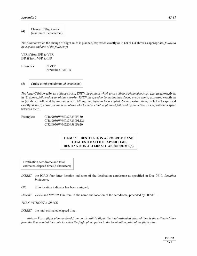
(4) Change of flight rules (maximum 3 characters)
The point at which the change of flight rules is planned, expressed exactly as in (2) or (3) above as appropriate, followed by a space and one of the following: VFR if from IFR to VFR IFR if from VFR to IFR Examples: LN VFR LN/N0284A050 IFR
(5) Cruise climb (maximum 28 characters)
The letter C followed by an oblique stroke; THEN the point at which cruise climb is planned to start, expressed exactly as in (2) above, followed by an oblique stroke; THEN the speed to be maintained during cruise climb, expressed exactly as in (a) above, followed by the two levels defining the layer to be occupied during cruise climb, each level expressed exactly as in (b) above, or the level above which cruise climb is planned followed by the letters PLUS, without a space between them. Examples: C/48N050W/M082F290F350 C/48N050W/M082F290PLUS C/52N050W/M220F580F620.
ITEM 16: DESTINATION AERODROME AND TOTAL ESTIMATED ELAPSED TIME,
DESTINATION ALTERNATE AERODROME(S)
Destination aerodrome and total estimated elapsed time (8 characters)
INSERT the ICAO four-letter location indicator of the destination aerodrome as specified in Doc 7910, Location
Indicators, OR, if no location indicator has been assigned, INSERT ZZZZ and SPECIFY in Item 18 the name and location of the aerodrome, preceded by DEST/ . THEN WITHOUT A SPACE INSERT the total estimated elapsed time. Note.— For a flight plan received from an aircraft in flight, the total estimated elapsed time is the estimated time from the first point of the route to which the flight plan applies to the termination point of the flight plan.
15/11/12 No. 1
A2-12 Air Traffic Management (PANS-ATM)
22/11/07
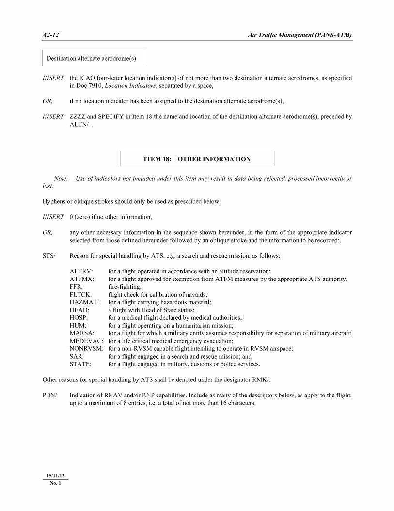
Destination alternate aerodrome(s)
INSERT the ICAO four-letter location indicator(s) of not more than two destination alternate aerodromes, as specified
in Doc 7910, Location Indicators, separated by a space, OR, if no location indicator has been assigned to the destination alternate aerodrome(s), INSERT ZZZZ and SPECIFY in Item 18 the name and location of the destination alternate aerodrome(s), preceded by
ALTN/ .
ITEM 18: OTHER INFORMATION
Note.— Use of indicators not included under this item may result in data being rejected, processed incorrectly or lost. Hyphens or oblique strokes should only be used as prescribed below. INSERT 0 (zero) if no other information, OR, any other necessary information in the sequence shown hereunder, in the form of the appropriate indicator
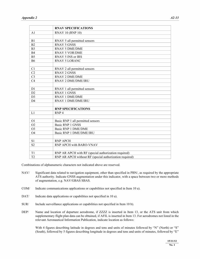
selected from those defined hereunder followed by an oblique stroke and the information to be recorded: STS/ Reason for special handling by ATS, e.g. a search and rescue mission, as follows: ALTRV: for a flight operated in accordance with an altitude reservation; ATFMX: for a flight approved for exemption from ATFM measures by the appropriate ATS authority; FFR: fire-fighting; FLTCK: flight check for calibration of navaids; HAZMAT: for a flight carrying hazardous material; HEAD: a flight with Head of State status; HOSP: for a medical flight declared by medical authorities; HUM: for a flight operating on a humanitarian mission; MARSA: for a flight for which a military entity assumes responsibility for separation of military aircraft; MEDEVAC: for a life critical medical emergency evacuation; NONRVSM: for a non-RVSM capable flight intending to operate in RVSM airspace; SAR: for a flight engaged in a search and rescue mission; and STATE: for a flight engaged in military, customs or police services. Other reasons for special handling by ATS shall be denoted under the designator RMK/. PBN/ Indication of RNAV and/or RNP capabilities. Include as many of the descriptors below, as apply to the flight,
up to a maximum of 8 entries, i.e. a total of not more than 16 characters.
15/11/12 No. 1
Appendix 2 A2-13
22/11/07
RNAV SPECIFICATIONS A1 RNAV 10 (RNP 10) B1 RNAV 5 all permitted sensors B2 RNAV 5 GNSS B3 RNAV 5 DME/DME B4 RNAV 5 VOR/DME B5 RNAV 5 INS or IRS B6 RNAV 5 LORANC C1 RNAV 2 all permitted sensors C2 RNAV 2 GNSS C3 RNAV 2 DME/DME C4 RNAV 2 DME/DME/IRU D1 RNAV 1 all permitted sensors D2 RNAV 1 GNSS D3 RNAV 1 DME/DME D4 RNAV 1 DME/DME/IRU RNP SPECIFICATIONS L1 RNP 4 O1 Basic RNP 1 all permitted sensors O2 Basic RNP 1 GNSS O3 Basic RNP 1 DME/DME O4 Basic RNP 1 DME/DME/IRU S1 RNP APCH S2 RNP APCH with BARO-VNAV T1 RNP AR APCH with RF (special authorization required) T2 RNP AR APCH without RF (special authorization required)
Combinations of alphanumeric characters not indicated above are reserved. NAV/ Significant data related to navigation equipment, other than specified in PBN/, as required by the appropriate
ATS authority. Indicate GNSS augmentation under this indicator, with a space between two or more methods of augmentation, e.g. NAV/GBAS SBAS.
COM/ Indicate communications applications or capabilities not specified in Item 10 a). DAT/ Indicate data applications or capabilities not specified in 10 a). SUR/ Include surveillance applications or capabilities not specified in Item 10 b). DEP/ Name and location of departure aerodrome, if ZZZZ is inserted in Item 13, or the ATS unit from which
supplementary flight plan data can be obtained, if AFIL is inserted in Item 13. For aerodromes not listed in the relevant Aeronautical Information Publication, indicate location as follows:
With 4 figures describing latitude in degrees and tens and units of minutes followed by “N” (North) or “S”
(South), followed by 5 figures describing longitude in degrees and tens and units of minutes, followed by “E”
15/11/12 No. 1
A2-14 Air Traffic Management (PANS-ATM)
22/11/07
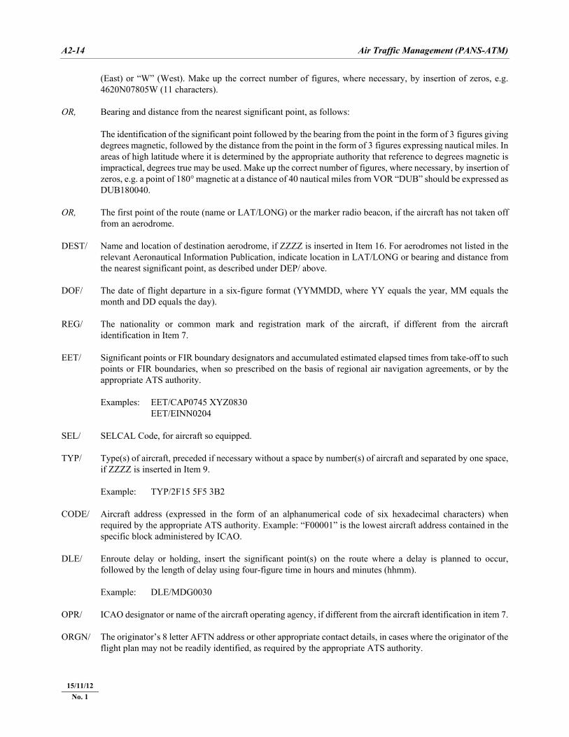
(East) or “W” (West). Make up the correct number of figures, where necessary, by insertion of zeros, e.g. 4620N07805W (11 characters).
OR, Bearing and distance from the nearest significant point, as follows: The identification of the significant point followed by the bearing from the point in the form of 3 figures giving
degrees magnetic, followed by the distance from the point in the form of 3 figures expressing nautical miles. In areas of high latitude where it is determined by the appropriate authority that reference to degrees magnetic is impractical, degrees true may be used. Make up the correct number of figures, where necessary, by insertion of zeros, e.g. a point of 180° magnetic at a distance of 40 nautical miles from VOR “DUB” should be expressed as DUB180040.
OR, The first point of the route (name or LAT/LONG) or the marker radio beacon, if the aircraft has not taken off
from an aerodrome. DEST/ Name and location of destination aerodrome, if ZZZZ is inserted in Item 16. For aerodromes not listed in the
relevant Aeronautical Information Publication, indicate location in LAT/LONG or bearing and distance from the nearest significant point, as described under DEP/ above.
DOF/ The date of flight departure in a six-figure format (YYMMDD, where YY equals the year, MM equals the
month and DD equals the day). REG/ The nationality or common mark and registration mark of the aircraft, if different from the aircraft
identification in Item 7. EET/ Significant points or FIR boundary designators and accumulated estimated elapsed times from take-off to such
points or FIR boundaries, when so prescribed on the basis of regional air navigation agreements, or by the appropriate ATS authority.
Examples: EET/CAP0745 XYZ0830 EET/EINN0204 SEL/ SELCAL Code, for aircraft so equipped. TYP/ Type(s) of aircraft, preceded if necessary without a space by number(s) of aircraft and separated by one space,
if ZZZZ is inserted in Item 9. Example: TYP/2F15 5F5 3B2 CODE/ Aircraft address (expressed in the form of an alphanumerical code of six hexadecimal characters) when
required by the appropriate ATS authority. Example: “F00001” is the lowest aircraft address contained in the specific block administered by ICAO.
DLE/ Enroute delay or holding, insert the significant point(s) on the route where a delay is planned to occur,
followed by the length of delay using four-figure time in hours and minutes (hhmm). Example: DLE/MDG0030 OPR/ ICAO designator or name of the aircraft operating agency, if different from the aircraft identification in item 7. ORGN/ The originator’s 8 letter AFTN address or other appropriate contact details, in cases where the originator of the
flight plan may not be readily identified, as required by the appropriate ATS authority.
15/11/12 No. 1
Appendix 2 A2-15
22/11/07
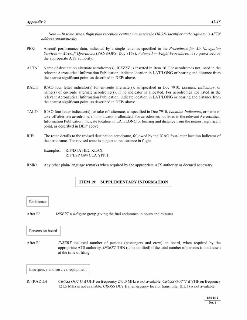
Note.— In some areas, flight plan reception centres may insert the ORGN/ identifier and originator’s AFTN address automatically.
PER/ Aircraft performance data, indicated by a single letter as specified in the Procedures for Air Navigation
Services — Aircraft Operations (PANS-OPS, Doc 8168), Volume I — Flight Procedures, if so prescribed by the appropriate ATS authority.
ALTN/ Name of destination alternate aerodrome(s), if ZZZZ is inserted in Item 16. For aerodromes not listed in the
relevant Aeronautical Information Publication, indicate location in LAT/LONG or bearing and distance from the nearest significant point, as described in DEP/ above.
RALT/ ICAO four letter indicator(s) for en-route alternate(s), as specified in Doc 7910, Location Indicators, or
name(s) of en-route alternate aerodrome(s), if no indicator is allocated. For aerodromes not listed in the relevant Aeronautical Information Publication, indicate location in LAT/LONG or bearing and distance from the nearest significant point, as described in DEP/ above.
TALT/ ICAO four letter indicator(s) for take-off alternate, as specified in Doc 7910, Location Indicators, or name of
take-off alternate aerodrome, if no indicator is allocated. For aerodromes not listed in the relevant Aeronautical Information Publication, indicate location in LAT/LONG or bearing and distance from the nearest significant point, as described in DEP/ above.
RIF/ The route details to the revised destination aerodrome, followed by the ICAO four-letter location indicator of
the aerodrome. The revised route is subject to reclearance in flight. Examples: RIF/DTA HEC KLAX RIF/ESP G94 CLA YPPH RMK/ Any other plain-language remarks when required by the appropriate ATS authority or deemed necessary.
ITEM 19: SUPPLEMENTARY INFORMATION
Endurance
After E/ INSERT a 4-figure group giving the fuel endurance in hours and minutes.
Persons on board
After P/ INSERT the total number of persons (passengers and crew) on board, when required by the
appropriate ATS authority. INSERT TBN (to be notified) if the total number of persons is not known at the time of filing.
Emergency and survival equipment
R/ (RADIO) CROSS OUT U if UHF on frequency 243.0 MHz is not available. CROSS OUT V if VHF on frequency
121.5 MHz is not available. CROSS OUT E if emergency locator transmitter (ELT) is not available.
15/11/12 No. 1
A2-16 Air Traffic Management (PANS-ATM)
22/11/07
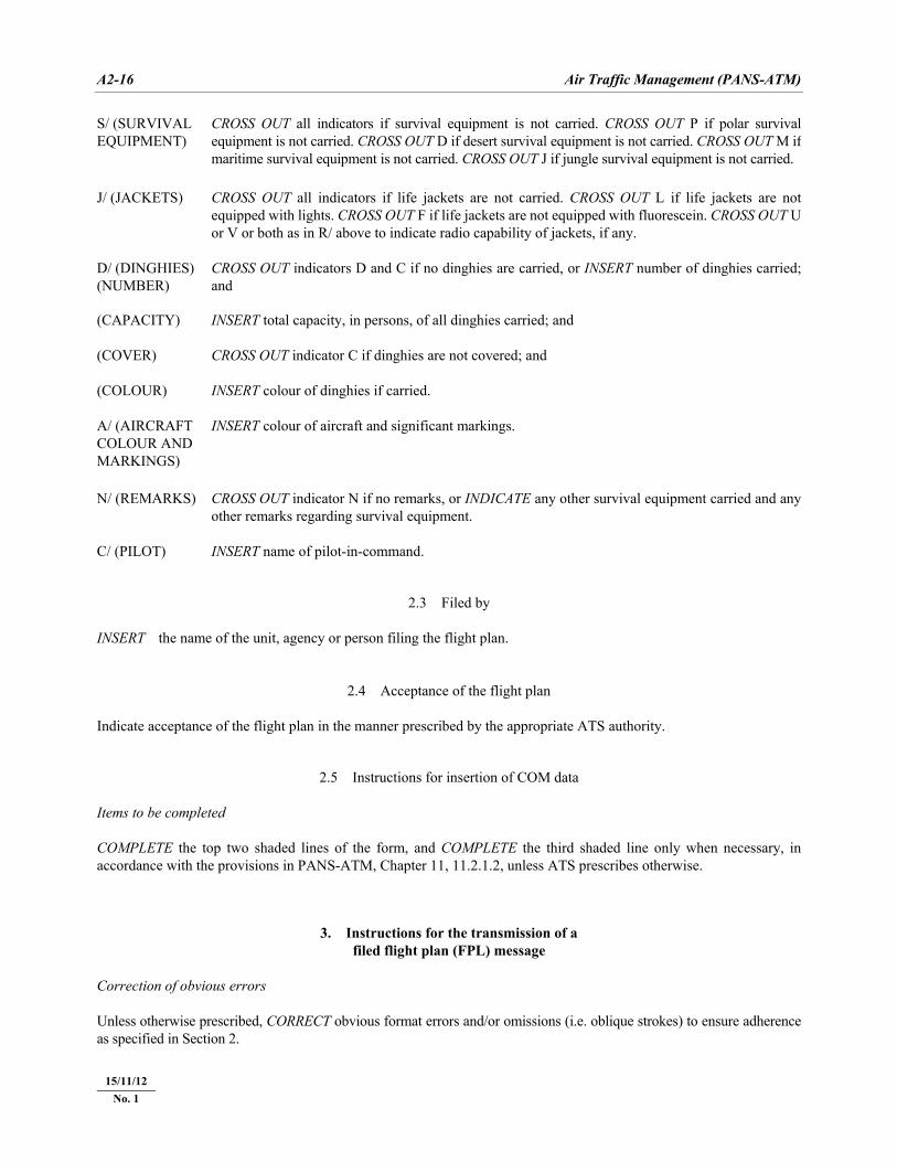
S/ (SURVIVAL EQUIPMENT)
CROSS OUT all indicators if survival equipment is not carried. CROSS OUT P if polar survival equipment is not carried. CROSS OUT D if desert survival equipment is not carried. CROSS OUT M if maritime survival equipment is not carried. CROSS OUT J if jungle survival equipment is not carried.
J/ (JACKETS) CROSS OUT all indicators if life jackets are not carried. CROSS OUT L if life jackets are not
equipped with lights. CROSS OUT F if life jackets are not equipped with fluorescein. CROSS OUT U or V or both as in R/ above to indicate radio capability of jackets, if any.
D/ (DINGHIES) (NUMBER)
CROSS OUT indicators D and C if no dinghies are carried, or INSERT number of dinghies carried; and
(CAPACITY) INSERT total capacity, in persons, of all dinghies carried; and (COVER) CROSS OUT indicator C if dinghies are not covered; and (COLOUR) INSERT colour of dinghies if carried. A/ (AIRCRAFT COLOUR AND MARKINGS)
INSERT colour of aircraft and significant markings.
N/ (REMARKS) CROSS OUT indicator N if no remarks, or INDICATE any other survival equipment carried and any
other remarks regarding survival equipment. C/ (PILOT) INSERT name of pilot-in-command.
2.3 Filed by INSERT the name of the unit, agency or person filing the flight plan.
2.4 Acceptance of the flight plan Indicate acceptance of the flight plan in the manner prescribed by the appropriate ATS authority.
2.5 Instructions for insertion of COM data Items to be completed COMPLETE the top two shaded lines of the form, and COMPLETE the third shaded line only when necessary, in accordance with the provisions in PANS-ATM, Chapter 11, 11.2.1.2, unless ATS prescribes otherwise.
3. Instructions for the transmission of a filed flight plan (FPL) message
Correction of obvious errors Unless otherwise prescribed, CORRECT obvious format errors and/or omissions (i.e. oblique strokes) to ensure adherence as specified in Section 2.
15/11/12 No. 1
Appendix 2 A2-17
22/11/07
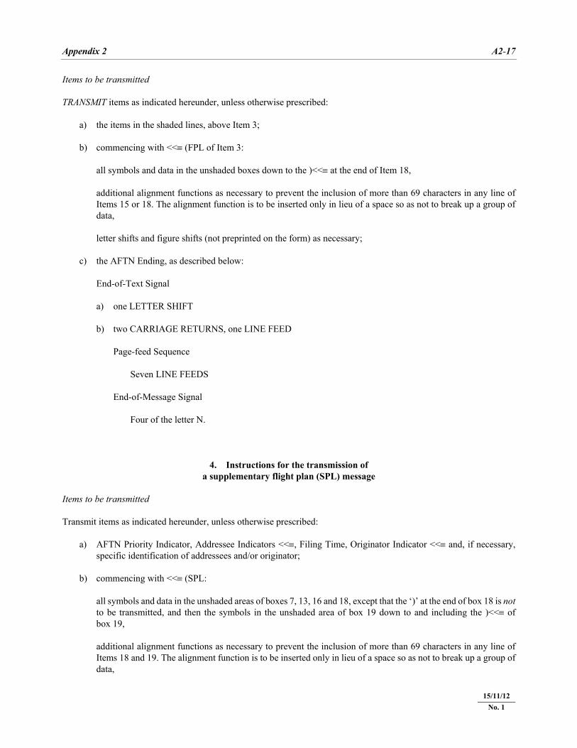
Items to be transmitted TRANSMIT items as indicated hereunder, unless otherwise prescribed: a) the items in the shaded lines, above Item 3; b) commencing with <<≡ (FPL of Item 3: all symbols and data in the unshaded boxes down to the )<<≡ at the end of Item 18, additional alignment functions as necessary to prevent the inclusion of more than 69 characters in any line of
Items 15 or 18. The alignment function is to be inserted only in lieu of a space so as not to break up a group of data,
letter shifts and figure shifts (not preprinted on the form) as necessary; c) the AFTN Ending, as described below: End-of-Text Signal a) one LETTER SHIFT b) two CARRIAGE RETURNS, one LINE FEED Page-feed Sequence Seven LINE FEEDS End-of-Message Signal Four of the letter N.
4. Instructions for the transmission of a supplementary flight plan (SPL) message
Items to be transmitted Transmit items as indicated hereunder, unless otherwise prescribed: a) AFTN Priority Indicator, Addressee Indicators <<≡, Filing Time, Originator Indicator <<≡ and, if necessary,
specific identification of addressees and/or originator; b) commencing with <<≡ (SPL: all symbols and data in the unshaded areas of boxes 7, 13, 16 and 18, except that the ‘)’ at the end of box 18 is not
to be transmitted, and then the symbols in the unshaded area of box 19 down to and including the )<<≡ of box 19,
additional alignment functions as necessary to prevent the inclusion of more than 69 characters in any line of
Items 18 and 19. The alignment function is to be inserted only in lieu of a space so as not to break up a group of data,
15/11/12 No. 1
A2-18 Air Traffic Management (PANS-ATM)
22/11/07
letter shifts and figure shifts (not preprinted on the form) as necessary; c) the AFTN Ending, as described below: End-of-Text Signal a) one LETTER SHIFT b) two CARRIAGE RETURNS, one LINE FEED Page-feed Sequence Seven LINE FEEDS End-of-Message Signal Four of the letter N.
15/11/12 No. 1
Appendix 2 A2-19
22/11/07
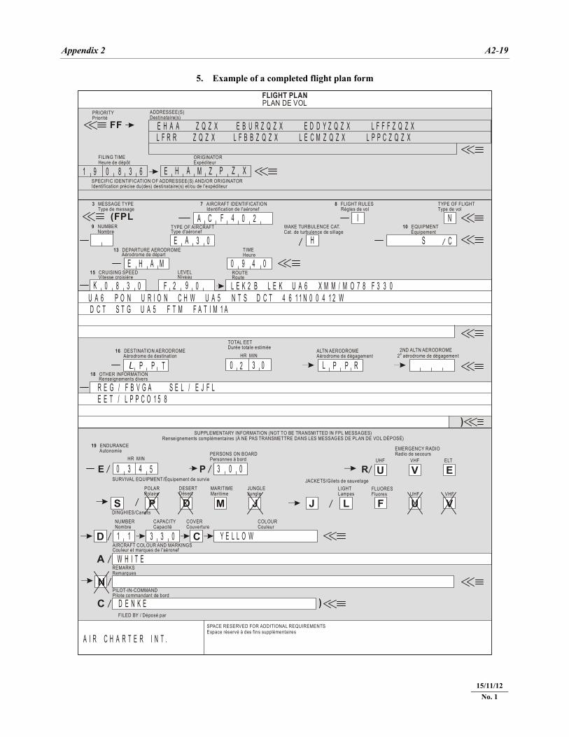
5. Example of a completed flight plan form
FILED BY / Déposé par
SPACE RESERVED FOR ADDITIONAL REQUIREMENTSEspace réservé à des fins supplémentaires
FLIGHT PLANPLAN DE VOL
PRIORITYPriorité
ADDRESSEE(S)Destinataire(s)
FF
(FPL
E P R
FILING TIMEHeure de dépôt
ORIGINATORExpéditeur
SPECIFIC IDENTIFICATION OF ADDRESSEE(S) AND/OR ORIGINATORIdentification précise du(des) destinataire(s) et/ou de l'expéditeur
3 MESSAGE TYPE Type de message
7 AIRCRAFT IDENTIFICATION Identification de l'aéronef
8 FLIGHT RULES Règles de vol
TYPE OF FLIGHTType de vol
9 NUMBER Nombre
TYPE OF AIRCRAFTType d'aéronef
WAKE TURBULENCE CAT.Cat. de turbulence de sil lage
10 EQUIPMENT Équipement
/
/
/
/
/
/
/
/
/
/
/TIMEHeure
13 DEPARTURE AERODROME Aérodrome de départ
15 CRUISING SPEED Vitesse croisière
LEVELNiveau
ROUTERoute
ALTN AERODROMEAérodrome de dégagement
16 DESTINATION AERODROME Aérodrome de destination
2ND ALTN AERODROMETOTAL EETDurée totale estimée
HR MIN
18 OTHER INFORMATION Renseignements divers
SUPPLEMENTARY INFORMATION (NOT TO BE TRANSMITTED IN FPL MESSAGES)Renseignements complémentaires (À NE PAS TRANSMETTRE DANS LES MESSAGES DE PLAN DE VOL DÉPOSÉ)
19 ENDURANCE Autonomie
HR MIN
EMERGENCY RADIORadio de secours
UHF VHF
VHFUHF
ELT
FLUORESFluores
LIGHTLampes
JUNGLEJungle
MARITIMEMaritime
DESERTDésert
POLARPolaire
SURVIVAL EQUIPMENT/Équipement de survie
DINGHIES/Canots
NUMBERNombre
CAPACITYCapacité
COVERCouverture
COLOURCouleur
AIRCRAFT COLOUR AND MARKINGSCouleur et marques de l'aéronef
)
)
PERSONS ON BOARDPersonnes à bord
REMARKSRemarques
PILOT-IN-COMMANDPilote commandant de bord
U
UFLJJMDPS
D
A
N
C
C
V
V
EJACKETS/Gilets de sauvetage
2 aérodrome de dégagemente
E H A A Z Q Z X E B U R Z Q Z X E D D Y Z Q Z X L F F F Z Q Z XL F R R Z Q Z X L F B B Z Q Z X L E C M Z Q Z X L P P C Z Q Z X
1 9 0 8 3 6 E H A M Z P Z X
A C F 4 0 2 I N
S CE A 3 0 H
E H A M 0 9 4 0
K 0 8 3 0 F 2 9 0 L E K 2 B L E K U A 6 X M M / M O 7 8 F 3 3 0U A 6 P O N U R I O N C H W U A 5 N T S D C T 4 6 1 1 N 0 0 4 1 2 WD C T S T G U A 5 F T M F A T I M 1 A
L LP PP PT 0 02 3 R
R E G / F B V G A S E L / E J F LE E T / L P P C O 1 5 8
0 3 4 5 3 0 0
1 1 3 3 0 Y E L L O W
W H I T E
D E N K E
A I R C H A R T E R I N T .
15/11/12 No. 1
A2-20
Air Traffic M
anagement (PA
NS-A
TM)
22/11/07
REPETITIVE FLIGHT PLAN LISTING A OPERATOR B ADDRESSEE(S) C DEPARTURE AERODROME(S) D
DATE
– – – – – – – yymmdd
E
SERIAL NO. _ _ - _ _
F
PAGE OF – – / – –
G SUPPLEMENTARY DATA (Item 19) AT:
H I J K L M N O P Q
+ –
VALID FROM
yymmdd
VALID UNTIL
yymmdd
DAYS OF OPERATION
AIRCRAFT IDENTIFI- CATION (Item 7)
TYPE OF AIRCRAFT
AND WAKE
TURBULENCE CATEGORY
(Item 9)
DEPARTURE AERODROME
AND TIME
(Item 13)
ROUTE (Item 15)
CRUISING
DESTINATION AERODROME
AND TOTAL
ESTIMATED ELAPSED TIME
(Item 16) REMARKS 1 2 3 4 5 6 7 SPEED LEVEL ROUTE
6. ICA
O m
odel repetitive flight plan (RPL
) listing form
15/11/12 N
o. 1
Appendix 2 A2-21
22/11/07
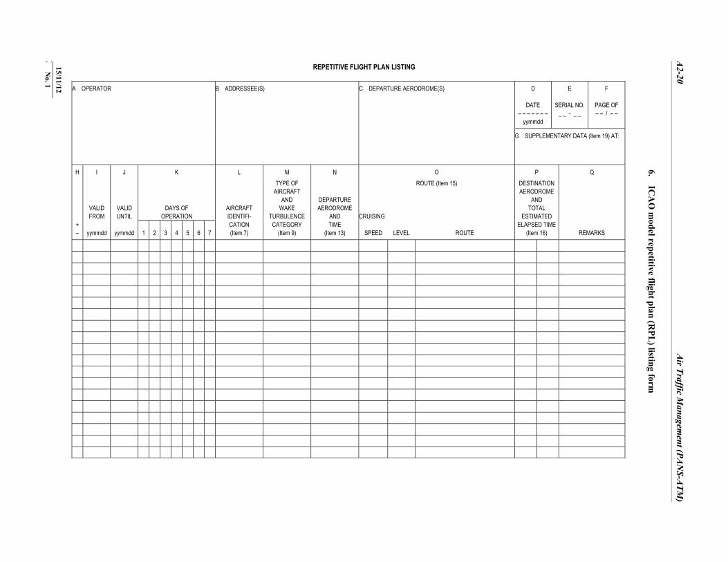
7. Instructions for the completion of the repetitive flight plan (RPL) listing form
7.1 General List only flight plans that will operate in accordance with IFR. (Flight rules I in FPL format). It is assumed that all aircraft are operating as scheduled flights (Type of flight S in FPL format), otherwise notify in Q (Remarks). It is assumed that all aircraft operating on RPLs are equipped with 4 096-code transponders with Modes A and C. Otherwise, notify in Q (Remarks). List flight plans in alphabetical order of the location indicator of the departure aerodrome. List flight plans for each departure aerodrome in chronological order of estimated off-block times. Adhere closely to the data conventions as indicated for the Flight Plan Form (Appendix 3, 1.6) unless otherwise specifically indicated in 7.4. Insert all clock times in 4 figures UTC. Insert all estimated elapsed times in 4 figures (hours and minutes). Insert data on a separate line for each segment of operations with one or more stops, i.e. from any departure aerodrome to the next destination aerodrome even though call sign or flight number is the same for multiple segments. Clearly identify additions and deletions in accordance with Item H at 7.4. Subsequent listings shall list the corrected and added data, and deleted flight plans shall be omitted. Number pages by indicating number of page and total number of pages in submission. Utilize more than one line for any RPL where the space provided for items O and Q on one line is not sufficient. 7.2 A flight shall be cancelled as follows: a) indicate a minus sign in Item H followed by all other items of the cancelled flight; b) insert a subsequent entry denoted by a plus sign in Item H and the date of the last flight in Item J, with all other
items of the cancelled flight unchanged. 7.3 Modification to a flight shall be made as follows: a) carry out the cancellation as indicated in 7.2; and b) insert a third entry giving the new flight plan(s) with the appropriate items modified as necessary, including the
new validity dates in Items I and J. Note.— All entries related to the same flight will be inserted in succession in the order specified above.
7.4 Instructions for insertion of RPL data Complete Items A to Q as indicated hereunder.
15/11/12 No. 1
A2-22 Air Traffic Management (PANS-ATM)
ITEM A: OPERATOR
INSERT name of operator.
ITEM B: ADDRESSEE(S)
INSERT name of agency(ies) designated by States to administer RPLs for FIRs or areas of responsibility concerned
with the route of flight.
ITEM C: DEPARTURE AERODROME(S)
INSERT location indicator(s) of departure aerodrome(s).
ITEM D: DATE
INSERT on each page of submission the date (year, month, day) in a 6-figure group that the listing was submitted.
ITEM E: SERIAL NO.
INSERT serial number of submission (2 numerics) indicating last two digits of year, a dash, and the sequential no. of the
submission for the year indicated (start with numeral 1 each new year).
ITEM F: PAGE OF
INSERT page number and total number of pages submitted.
ITEM G: SUPPLEMENTARY DATA AT
INSERT name and appropriate contact details of entity where information normally provided under Item 19 of the FPL
is kept readily available and can be supplied without delay.
ITEM H: ENTRY TYPE
INSERT a minus sign (–) for each flight plan that is to be deleted from the listing. INSERT a plus sign (+) for each initial listing and, in the case of subsequent submissions, for each flight plan not listed
in the previous submission. Note.— No information is required under this item for any flight plan which is unchanged from the previous submission.
15/11/12 No. 1
Appendix 2 A2-23
22/11/07
ITEM I: VALID FROM
INSERT first date (year, month, day) upon which the flight is scheduled to operate.
ITEM J: VALID UNTIL
INSERT last date (year, month, day) upon which the flight is scheduled to operate as listed, or UFN if the duration is unknown.
ITEM K: DAYS OF OPERATION
INSERT number corresponding to the day of the week in the appropriate column; Monday = 1 through Sunday = 7. INSERT 0 for each day of non-operation in the appropriate column.
ITEM L: AIRCRAFT IDENTIFICATION
(Item 7 of the ICAO flight plan) INSERT aircraft identification to be used for the flight.
ITEM M: TYPE OF AIRCRAFT AND WAKE TURBULENCE CATEGORY
(Item 9 of the ICAO flight plan) INSERT appropriate ICAO designator as specified in ICAO Doc 8643 — Aircraft Type Designators. INSERT H, M or L indicator as appropriate: H — HEAVY to indicate an aircraft type with a maximum certificated take-off mass of 136 000 kg or more, M — MEDIUM to indicate an aircraft type with a maximum certificated take-off mass of less than
136 000 kg but more than 7 000 kg, L — LIGHT to indicate an aircraft type with a maximum certificated take-off mass of 7 000 kg or less.
15/11/12 No. 1
A2-24 Air Traffic Management (PANS-ATM)
ITEM N: DEPARTURE AERODROME AND TIME
(Item 13 of the ICAO flight plan) INSERT location indicator of the departure aerodrome. INSERT the off-block time, i.e. the estimated time that the aircraft will commence movement associated with departure.
ITEM O: ROUTE
(Item 15 of the ICAO flight plan)
(a) Cruising speed
INSERT the true airspeed for the first or whole cruising portion of the flight in accordance with Item 15 (a) of the ICAO
flight plan.
(b) Cruising level
INSERT the planned cruising level for the first or whole portion of the route in accordance with Item 15 (b) of the ICAO
flight plan.
(c) Route
INSERT the entire route in accordance with Item 15 (c) of the ICAO flight plan.
ITEM P: DESTINATION AERODROME AND TOTAL ESTIMATED ELAPSED TIME
(Item 16 of the ICAO flight plan) INSERT location indicator of the destination aerodrome. INSERT the total estimated elapsed time.
ITEM Q: REMARKS
INSERT items of information as required by the appropriate ATS authority, items normally notified in Item 18 of the
ICAO flight plan and any other information pertinent to the flight of concern to ATS.
15/11/12 No. 1
Appendix 2
A2-25
22/11/07
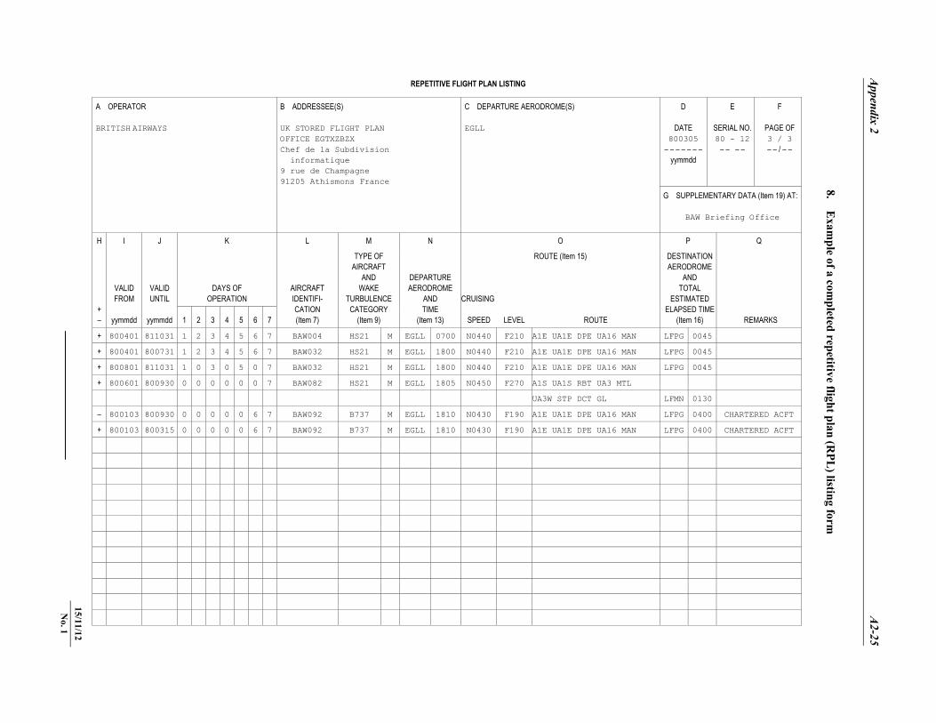
REPETITIVE FLIGHT PLAN LISTING A OPERATOR BRITISH AIRWAYS
B ADDRESSEE(S) UK STORED FLIGHT PLAN OFFICE EGTXZBZX Chef de la Subdivision informatique 9 rue de Champagne 91205 Athismons France
C DEPARTURE AERODROME(S) EGLL
D
DATE 800305
– – – – – – – yymmdd
E
SERIAL NO. 80 - 12
– – – –
F
PAGE OF 3 / 3 – – / – –
G SUPPLEMENTARY DATA (Item 19) AT:
BAW Briefing Office
H I J K L M N O P Q
+ –
VALID FROM
yymmdd
VALID UNTIL
yymmdd
DAYS OF OPERATION
AIRCRAFT IDENTIFI- CATION (Item 7)
TYPE OF AIRCRAFT
AND WAKE
TURBULENCE CATEGORY
(Item 9)
DEPARTURE AERODROME
AND TIME
(Item 13)
ROUTE (Item 15)
CRUISING
DESTINATION AERODROME
AND TOTAL
ESTIMATED ELAPSED TIME
(Item 16) REMARKS 1 2 3 4 5 6 7 SPEED LEVEL ROUTE
+ 800401 811031 1 2 3 4 5 6 7 BAW004 HS21 M EGLL 0700 N0440 F210 A1E UA1E DPE UA16 MAN LFPG 0045
+ 800401 800731 1 2 3 4 5 6 7 BAW032 HS21 M EGLL 1800 N0440 F210 A1E UA1E DPE UA16 MAN LFPG 0045
+ 800801 811031 1 0 3 0 5 0 7 BAW032 HS21 M EGLL 1800 N0440 F210 A1E UA1E DPE UA16 MAN LFPG 0045
+ 800601 800930 0 0 0 0 0 0 7 BAW082 HS21 M EGLL 1805 N0450 F270 A1S UA1S RBT UA3 MTL
UA3W STP DCT GL LFMN 0130
– 800103 800930 0 0 0 0 0 6 7 BAW092 B737 M EGLL 1810 N0430 F190 A1E UA1E DPE UA16 MAN LFPG 0400 CHARTERED ACFT
+ 800103 800315 0 0 0 0 0 6 7 BAW092 B737 M EGLL 1810 N0430 F190 A1E UA1E DPE UA16 MAN LFPG 0400 CHARTERED ACFT
8. Exam
ple of a completed repetitive flight plan (R
PL) listing form
15/11/12 N
o. 1

�������
PANS-ATM A3-1 22/11/07
Appendix 3
AIR TRAFFIC SERVICES MESSAGES
1. Message contents, formats and data conventions 2. Examples of ATS messages
A3-2 Air Traffic Management (PANS-ATM)
22/11/07
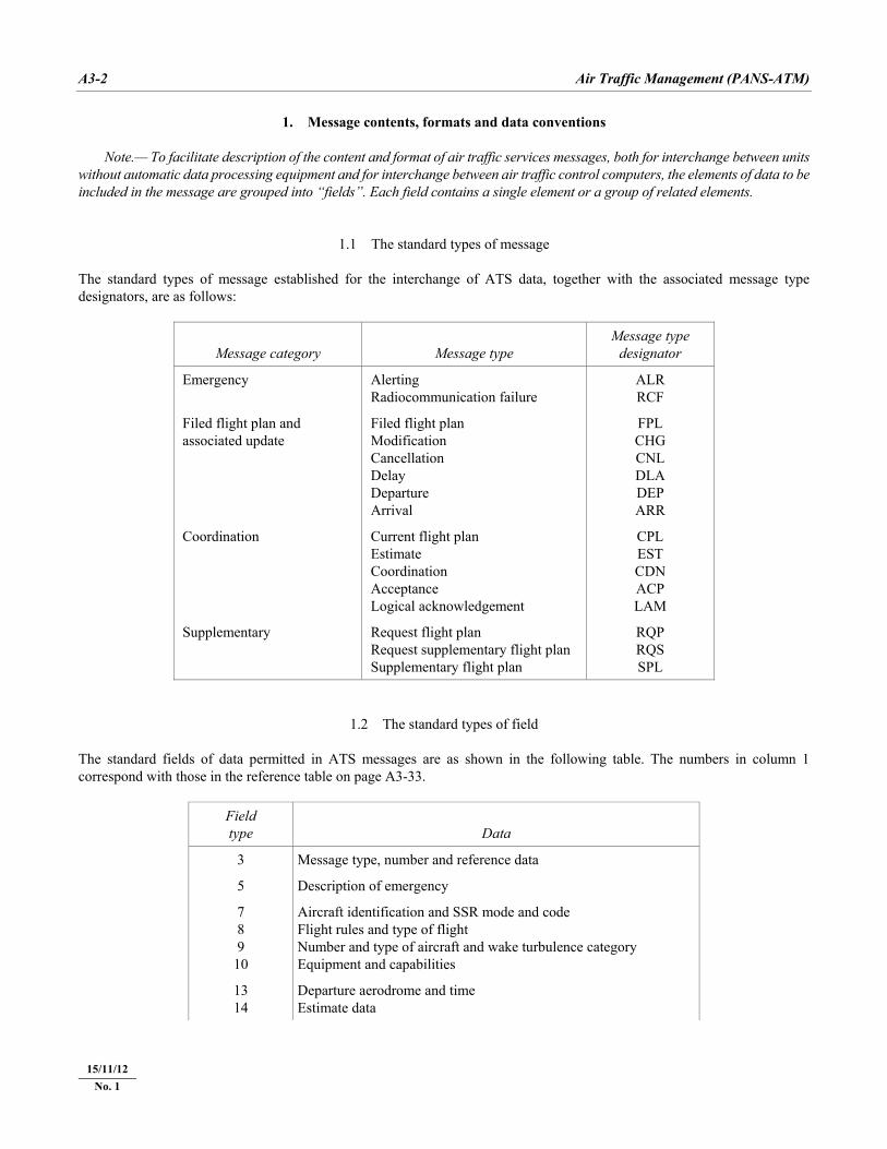
1. Message contents, formats and data conventions Note.— To facilitate description of the content and format of air traffic services messages, both for interchange between units without automatic data processing equipment and for interchange between air traffic control computers, the elements of data to be included in the message are grouped into “fields”. Each field contains a single element or a group of related elements.
1.1 The standard types of message The standard types of message established for the interchange of ATS data, together with the associated message type designators, are as follows:
Message category Message type Message type
designator
Emergency Alerting Radiocommunication failure
ALR RCF
Filed flight plan and associated update
Filed flight plan Modification Cancellation Delay Departure Arrival
FPL CHG CNL DLA DEP ARR
Coordination Current flight plan Estimate Coordination Acceptance Logical acknowledgement
CPL EST CDN ACP LAM
Supplementary Request flight plan Request supplementary flight plan Supplementary flight plan
RQP RQS SPL
1.2 The standard types of field The standard fields of data permitted in ATS messages are as shown in the following table. The numbers in column 1 correspond with those in the reference table on page A3-33.
Field type Data
3 Message type, number and reference data
5 Description of emergency
7 8 9
10
Aircraft identification and SSR mode and code Flight rules and type of flight Number and type of aircraft and wake turbulence category Equipment and capabilities
13 14
Departure aerodrome and time Estimate data
15/11/12 No. 1
Appendix 3 A3-3
22/11/07
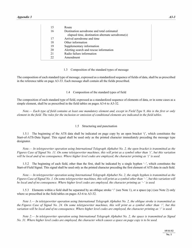
15 16
17 18 19 20 21 22
Route Destination aerodrome and total estimated elapsed time, destination alternate aerodrome(s) Arrival aerodrome and time Other information Supplementary information Alerting search and rescue information Radio failure information Amendment
1.3 Composition of the standard types of message The composition of each standard type of message, expressed as a standardized sequence of fields of data, shall be as prescribed in the reference table on page A3-33. Each message shall contain all the fields prescribed.
1.4 Composition of the standard types of field The composition of each standard type of field, expressed as a standardized sequence of elements of data, or in some cases as a simple element, shall be as prescribed in the field tables on pages A3-6 to A3-32. Note.— Each type of field contains at least one mandatory element and, except in Field Type 9, this is the first or only element in the field. The rules for the inclusion or omission of conditional elements are indicated in the field tables.
1.5 Structuring and punctuation 1.5.1 The beginning of the ATS data shall be indicated on page copy by an open bracket ‘(’, which constitutes the Start-of-ATS-Data Signal. This signal shall be used only as the printed character immediately preceding the message type designator. Note.— In teletypewriter operation using International Telegraph Alphabet No. 2, the open bracket is transmitted as the Figures Case of Signal No. 11. On some teletypewriter machines, this will print as a symbol other than ‘(’, but this variation will be local and of no consequence. Where higher level codes are employed, the character printing as ‘(’ is used. 1.5.2 The beginning of each field, other than the first, shall be indicated by a single hyphen ‘–’, which constitutes the Start-of-Field Signal. This signal shall be used only as the printed character preceding the first element of ATS data in each field. Note.— In teletypewriter operation using International Telegraph Alphabet No. 2, the single hyphen is transmitted as the Figures Case of Signal No. 1. On some teletypewriter machines, this will print as a symbol other than ‘–’, but this variation will be local and of no consequence. Where higher level codes are employed, the character printing as ‘–’ is used. 1.5.3 Elements within a field shall be separated by an oblique stroke ‘/’ (see Note 1), or a space (sp.) (see Note 2) only where so prescribed in the field tables on pages A3-6 to A3-32. Note 1.— In teletypewriter operation using International Telegraph Alphabet No. 2, the oblique stroke is transmitted as the Figures Case of Signal No. 24. On some teletypewriter machines, this will print as a symbol other than ‘/’, but this variation will be local and of no consequence. Where higher level codes are employed, the character printing as ‘/’ is used. Note 2.— In teletypewriter operation using International Telegraph Alphabet No. 2, the space is transmitted as Signal No. 31. Where higher level codes are employed, the character which causes a space on page copy is to be used.
15/11/12 No. 1
A3-4 Air Traffic Management (PANS-ATM)
22/11/07
1.5.4 The end of the ATS data shall be indicated by a close bracket ‘)’, which constitutes the End-of-ATS-Data Signal. This signal shall be used only as the printed character immediately following the last field in the message. Note.— In teletypewriter operation using International Telegraph Alphabet No. 2, the close bracket is transmitted as Signal No. 12. On some teletypewriter machines, this will print as a symbol other than ‘)’, but this variation will be local and of no consequence. Where higher level codes are employed, the character printing as ‘)’ is to be used. 1.5.5 When the standard ATS messages are prepared in teletypewriter form, an Alignment Function (two Carriage Returns followed by one Line Feed) shall be inserted: a) prior to each of the fields so annotated in the reference table on page A3-33; b) in Fields Type 5 (Description of emergency), 15 (Route), 18 (Other information), 19 (Supplementary information), 20
(Alerting search and rescue information), 21 (Radio failure information) and 22 (Amendment), whenever it is necessary to begin a new line on page copy (see Note). In such cases, the Alignment Function shall be inserted between two data elements and shall not divide an element.
Note.— Annex 10, Volume II, prescribes that a line of teletypewriter copy shall not contain more than
69 characters.
1.6 Data conventions 1.6.1 Most of the conventions to be used in the expression of ATS data in the messages are prescribed in the field tables on pages A3-6 to A3-32, but the conventions for the expression of level, position and route data are given below to simplify the field tables. 1.6.2 The expression of level data Four alternative conventions are available for the expression of level data: a) “F” followed by 3 decimal numerics: indicates a flight level number, i.e. Flight Level 330 is expressed as “F330”; b) “S” followed by 4 decimal numerics: indicates standard metric level in tens of metres, i.e. Standard Metric Level 11
300 metres (Flight Level 370) is expressed as “S1130”; c) “A” followed by 3 decimal numerics: indicates altitude in hundreds of feet, i.e. an altitude of 4 500 feet is expressed as
“A045”; d) “M” followed by 4 decimal numerics: indicates altitude in tens of metres, i.e. an altitude of 8 400 metres is expressed
as “M0840”. 1.6.3 The expression of position or route The following alternative data conventions shall be used for the expression of position or route: a) from 2 to 7 characters, being the coded designator assigned to an ATS route to be flown; b) from 2 to 5 characters, being the coded designator assigned to an en-route point;
Appendix 3 A3-5
22/11/07
c) 4 numerics describing latitude in degrees and tens and units of minutes, followed by “N” (meaning “North”) or “S” (South), followed by 5 numerics describing longitude in degrees and tens and units of minutes, followed by “E” (East) or “W” (West). The correct number of numerics is to be made up, where necessary, by the insertion of zeros, e.g. “4620N07805W”;
d) 2 numerics describing latitude in degrees, followed by “N” (North) or “S” (South), followed by 3 numerics
describing longitude in degrees, followed by “E” (East) or “W” (West). Again, the correct number of numerics is to be made up, where necessary, by the insertion of zeros, e.g. “46N078W”;
e) 2 to 5 characters being the coded identification of a significant point, followed by 3 decimal numerics giving the
bearing from the point in degrees magnetic followed by 3 decimal numerics giving the distance from the point in nautical miles. In areas of high latitude where it is determined by the appropriate authority that reference to degrees magnetic is impractical, degrees true may be used. The correct number of numerics is to be made up, where necessary, by the insertion of zeros, e.g. a point at 180° magnetic at a distance of 40 nautical miles from VOR “FOJ” would be expressed as “FOJ180040”.
1.7 The detail of the fields 1.7.1 The elements of data prescribed or permitted to be included in each type of field, together with a prescription of the conditions or options permitted, are shown on pages A3-6 to A3-32. 1.7.2 A key appears at the right-hand side of each of the field pages; this key permits the sequence of fields in each type of message to be followed. 1.7.3 The first field in each message type is Field Type 3; on the page describing Field Type 3 a key indicates the field type number of the next field for each message. On subsequent field pages, the field type number of the previous field is shown to permit back reference also. The Start-of-ATS-Data Signal ‘(’ is used in the key to indicate that there is no previous type of field; the End-of-ATS-Data Signal ‘)’ is used to indicate that there is no next type of field. 1.7.4 On the field pages, elements with a fixed number of characters are shown diagrammatically as (three characters in this example)
elements of variable length are shown as
1.8 Accuracy in the preparation of ATS messages Where the standard ATS messages are transmitted by teletypewriter channels in areas where ATC computers are known to be in use, the formats and data conventions prescribed in the field tables on pages A3-6 to A3-32 shall be adhered to rigorously.
15/11/12 No. 1
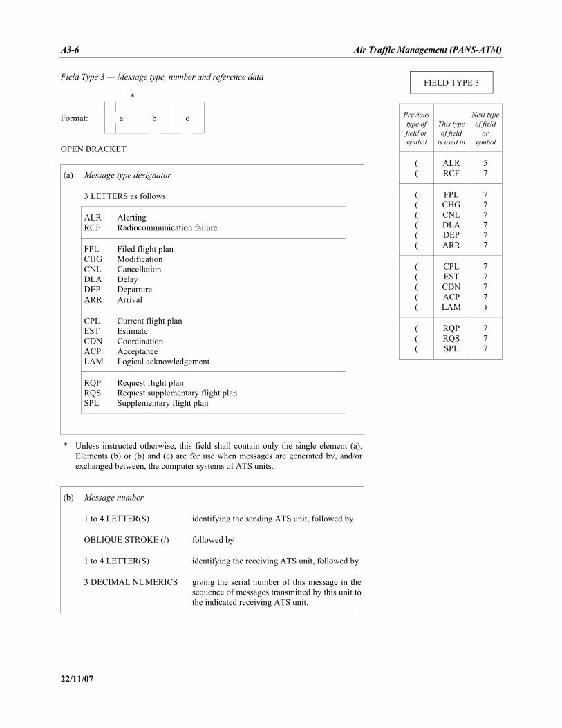
A3-6 Air Traffic Management (PANS-ATM)
22/11/07
Field Type 3 — Message type, number and reference data * Format: a b c OPEN BRACKET
(a) Message type designator
3 LETTERS as follows:
ALR RCF
Alerting Radiocommunication failure
FPL CHG CNL DLA DEP ARR
Filed flight plan Modification Cancellation Delay Departure Arrival
CPL EST CDN ACP LAM
Current flight plan Estimate Coordination Acceptance Logical acknowledgement
RQP RQS SPL
Request flight plan Request supplementary flight plan Supplementary flight plan
* Unless instructed otherwise, this field shall contain only the single element (a).Elements (b) or (b) and (c) are for use when messages are generated by, and/or exchanged between, the computer systems of ATS units.
(b) Message number
1 to 4 LETTER(S) identifying the sending ATS unit, followed by
OBLIQUE STROKE (/) followed by
1 to 4 LETTER(S) identifying the receiving ATS unit, followed by
3 DECIMAL NUMERICS giving the serial number of this message in the sequence of messages transmitted by this unit to the indicated receiving ATS unit.
FIELD TYPE 3
Previous type of field or symbol
This type of field
is used in
Next typeof field
or symbol
( (
ALR RCF
5 7
( ( ( ( ( (
FPL CHG CNL DLA DEP ARR
7 7 7 7 7 7
( ( ( ( (
CPL EST CDN ACP LAM
7 7 7 7 )
( ( (
RQP RQS SPL
7 7 7
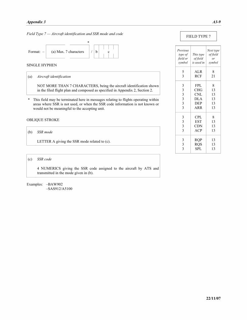
Appendix 3 A3-9
22/11/07
Field Type 7 — Aircraft identification and SSR mode and code *
/
Format: – (a) Max. 7 characters b c SINGLE HYPHEN
(a) Aircraft identification
NOT MORE THAN 7 CHARACTERS, being the aircraft identification shown in the filed flight plan and composed as specified in Appendix 2, Section 2.
* This field may be terminated here in messages relating to flights operating within areas where SSR is not used, or when the SSR code information is not known or would not be meaningful to the accepting unit.
OBLIQUE STROKE
(b) SSR mode
LETTER A giving the SSR mode related to (c).
(c) SSR code
4 NUMERICS giving the SSR code assigned to the aircraft by ATS and transmitted in the mode given in (b).
Examples: –BAW902 –SAS912/A5100
FIELD TYPE 7
Previous type of field or symbol
This type of field
is used in
Next typeof field
or symbol
5 3
ALR RCF
8 21
3 3 3 3 3 3
FPL CHG CNL DLA DEP ARR
8 13 13 13 13 13
3 3 3 3
CPL EST CDN ACP
8 13 13 13
3 3 3
RQP RQS SPL
13 13 13
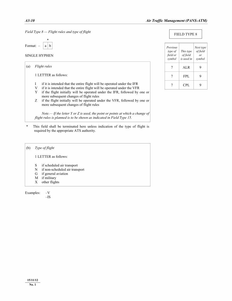
A3-10 Air Traffic Management (PANS-ATM)
22/11/07
Field Type 8 — Flight rules and type of flight
* Format: – a b SINGLE HYPHEN
(a) Flight rules
1 LETTER as follows:
I if it is intended that the entire flight will be operated under the IFR V if it is intended that the entire flight will be operated under the VFR Y if the flight initially will be operated under the IFR, followed by one or
more subsequent changes of flight rules Z if the flight initially will be operated under the VFR, followed by one or
more subsequent changes of flight rules
Note.— If the letter Y or Z is used, the point or points at which a change of flight rules is planned is to be shown as indicated in Field Type 15.
* This field shall be terminated here unless indication of the type of flight is required by the appropriate ATS authority.
(b) Type of flight
1 LETTER as follows:
S if scheduled air transport N if non-scheduled air transport G if general aviation M if military X other flights
Examples: –V –IS
FIELD TYPE 8
Previous type of field or symbol
This type of field
is used in
Next typeof field
or symbol
7 ALR 9
7 FPL 9
7 CPL 9
15/11/12 No. 1
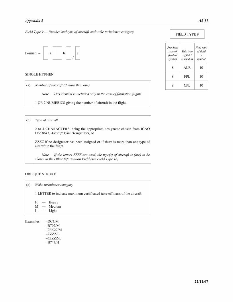
Appendix 3 A3-11
22/11/07
Field Type 9 — Number and type of aircraft and wake turbulence category
/
Format: – a b c SINGLE HYPHEN
(a) Number of aircraft (if more than one)
Note.— This element is included only in the case of formation flights.
1 OR 2 NUMERICS giving the number of aircraft in the flight.
(b) Type of aircraft
2 to 4 CHARACTERS, being the appropriate designator chosen from ICAO Doc 8643, Aircraft Type Designators, or
ZZZZ if no designator has been assigned or if there is more than one type of aircraft in the flight.
Note.— If the letters ZZZZ are used, the type(s) of aircraft is (are) to be shown in the Other Information Field (see Field Type 18).
OBLIQUE STROKE
(c) Wake turbulence category
1 LETTER to indicate maximum certificated take-off mass of the aircraft:
H — Heavy M — Medium L — Light
Examples: –DC3/M –B707/M –2FK27/M –ZZZZ/L –3ZZZZ/L –B747/H
FIELD TYPE 9
Previous type of field or symbol
This type of field
is used in
Next typeof field
or symbol
8 ALR 10
8 FPL 10
8 CPL 10
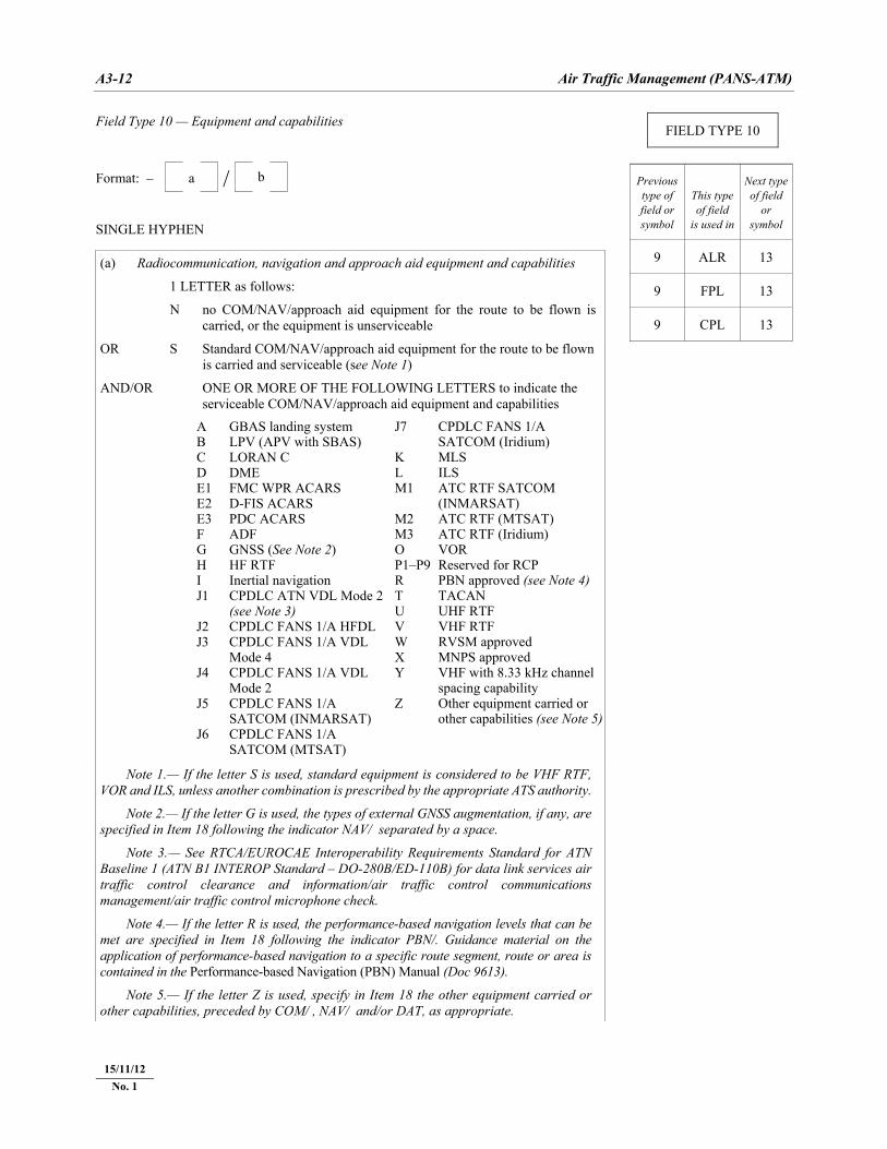
A3-12 Air Traffic Management (PANS-ATM)
22/11/07
Field Type 10 — Equipment and capabilities
/
Format: – a b
SINGLE HYPHEN (a) Radiocommunication, navigation and approach aid equipment and capabilities
1 LETTER as follows:
N no COM/NAV/approach aid equipment for the route to be flown is carried, or the equipment is unserviceable
OR S Standard COM/NAV/approach aid equipment for the route to be flown is carried and serviceable (see Note 1)
AND/OR ONE OR MORE OF THE FOLLOWING LETTERS to indicate the serviceable COM/NAV/approach aid equipment and capabilities
A B C D E1 E2 E3 F G H I J1 J2 J3 J4 J5 J6
GBAS landing system LPV (APV with SBAS) LORAN C DME FMC WPR ACARS D-FIS ACARS PDC ACARS ADF GNSS (See Note 2) HF RTF Inertial navigation CPDLC ATN VDL Mode 2 (see Note 3) CPDLC FANS 1/A HFDL CPDLC FANS 1/A VDL Mode 4 CPDLC FANS 1/A VDL Mode 2 CPDLC FANS 1/A SATCOM (INMARSAT) CPDLC FANS 1/A SATCOM (MTSAT)
J7 K L M1 M2 M3 O P1–P9R T U V W X Y Z
CPDLC FANS 1/A SATCOM (Iridium) MLS ILS ATC RTF SATCOM (INMARSAT) ATC RTF (MTSAT) ATC RTF (Iridium) VOR Reserved for RCP PBN approved (see Note 4) TACAN UHF RTF VHF RTF RVSM approved MNPS approved VHF with 8.33 kHz channel spacing capability Other equipment carried or other capabilities (see Note 5)
Note 1.— If the letter S is used, standard equipment is considered to be VHF RTF, VOR and ILS, unless another combination is prescribed by the appropriate ATS authority.
Note 2.— If the letter G is used, the types of external GNSS augmentation, if any, are specified in Item 18 following the indicator NAV/ separated by a space.
Note 3.— See RTCA/EUROCAE Interoperability Requirements Standard for ATN Baseline 1 (ATN B1 INTEROP Standard – DO-280B/ED-110B) for data link services air traffic control clearance and information/air traffic control communications management/air traffic control microphone check.
Note 4.— If the letter R is used, the performance-based navigation levels that can be met are specified in Item 18 following the indicator PBN/. Guidance material on the application of performance-based navigation to a specific route segment, route or area is contained in the Performance-based Navigation (PBN) Manual (Doc 9613).
Note 5.— If the letter Z is used, specify in Item 18 the other equipment carried or other capabilities, preceded by COM/ , NAV/ and/or DAT, as appropriate.
FIELD TYPE 10
Previous type of field or symbol
This type of field
is used in
Next typeof field
or symbol
9 ALR 13
9 FPL 13
9 CPL 13
15/11/12 No. 1
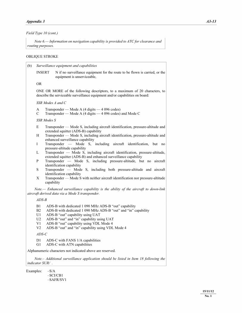
Appendix 3 A3-13
22/11/07
Field Type 10 (cont.) Note 6.— Information on navigation capability is provided to ATC for clearance and routing purposes.
OBLIQUE STROKE (b) Surveillance equipment and capabilities
INSERT N if no surveillance equipment for the route to be flown is carried, or the equipment is unserviceable,
OR ONE OR MORE of the following descriptors, to a maximum of 20 characters, to describe the serviceable surveillance equipment and/or capabilities on board: SSR Modes A and C
A C
Transponder — Mode A (4 digits — 4 096 codes)Transponder — Mode A (4 digits — 4 096 codes) and Mode C
SSR Modes S
E H I L P S X
Transponder — Mode S, including aircraft identification, pressure-altitude and extended squitter (ADS-B) capability Transponder — Mode S, including aircraft identification, pressure-altitude and enhanced surveillance capability Transponder — Mode S, including aircraft identification, but no pressure-altitude capability Transponder — Mode S, including aircraft identification, pressure-altitude, extended squitter (ADS-B) and enhanced surveillance capability Transponder — Mode S, including pressure-altitude, but no aircraft identification capability Transponder — Mode S, including both pressure-altitude and aircraft identification capability Transponder — Mode S with neither aircraft identification nor pressure-altitude capability
Note.— Enhanced surveillance capability is the ability of the aircraft to down-link aircraft derived data via a Mode S transponder.
ADS-B
B1 B2 U1 U2 V1 V2
ADS-B with dedicated 1 090 MHz ADS-B “out” capability ADS-B with dedicated 1 090 MHz ADS-B “out” and “in” capability ADS-B “out” capability using UAT ADS-B “out” and “in” capability using UAT ADS-B “out” capability using VDL Mode 4 ADS-B “out” and “in” capability using VDL Mode 4
ADS-C
D1 G1
ADS-C with FANS 1/A capabilitiesADS-C with ATN capabilities
Alphanumeric characters not indicated above are reserved. Note.– Additional surveillance application should be listed in Item 18 following the indicator SUR/ .
Examples: –S/A –SCI/CB1 –SAFR/SV1
15/11/12 No. 1
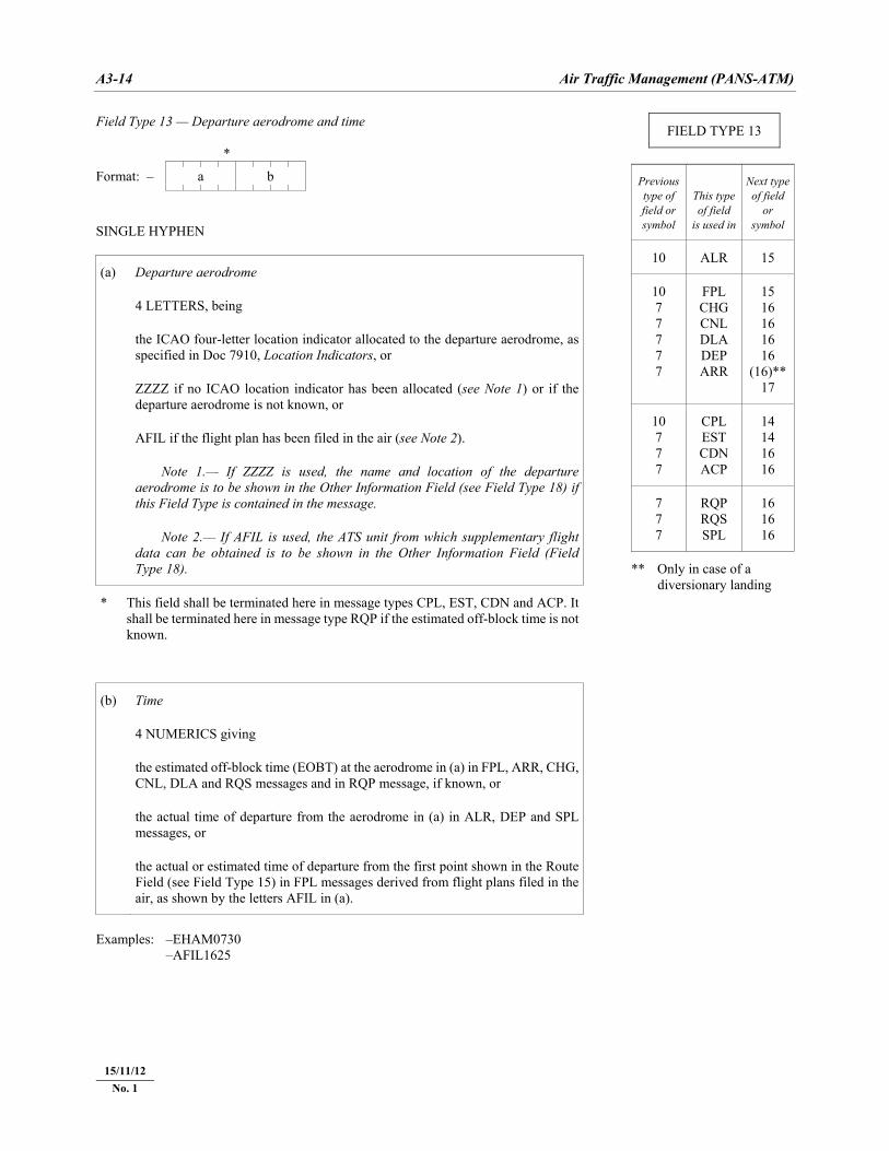
A3-14 Air Traffic Management (PANS-ATM)
22/11/07
Field Type 13 — Departure aerodrome and time *
Format: – a b
SINGLE HYPHEN
(a) Departure aerodrome
4 LETTERS, being
the ICAO four-letter location indicator allocated to the departure aerodrome, as specified in Doc 7910, Location Indicators, or
ZZZZ if no ICAO location indicator has been allocated (see Note 1) or if the departure aerodrome is not known, or
AFIL if the flight plan has been filed in the air (see Note 2).
Note 1.— If ZZZZ is used, the name and location of the departure aerodrome is to be shown in the Other Information Field (see Field Type 18) if this Field Type is contained in the message.
Note 2.— If AFIL is used, the ATS unit from which supplementary flight data can be obtained is to be shown in the Other Information Field (Field Type 18).
* This field shall be terminated here in message types CPL, EST, CDN and ACP. It shall be terminated here in message type RQP if the estimated off-block time is not known.
(b) Time
4 NUMERICS giving
the estimated off-block time (EOBT) at the aerodrome in (a) in FPL, ARR, CHG, CNL, DLA and RQS messages and in RQP message, if known, or
the actual time of departure from the aerodrome in (a) in ALR, DEP and SPL messages, or
the actual or estimated time of departure from the first point shown in the Route Field (see Field Type 15) in FPL messages derived from flight plans filed in the air, as shown by the letters AFIL in (a).
Examples: –EHAM0730 –AFIL1625
FIELD TYPE 13
Previous type of field or symbol
This type of field
is used in
Next typeof field
or symbol
10 ALR 15
10 7 7 7 7 7
FPL CHG CNL DLA DEP ARR
15 16 16 16 16
(16)** 17
10 7 7 7
CPL EST CDN ACP
14 14 16 16
7 7 7
RQP RQS SPL
16 16 16
** Only in case of a diversionary landing
15/11/12 No. 1
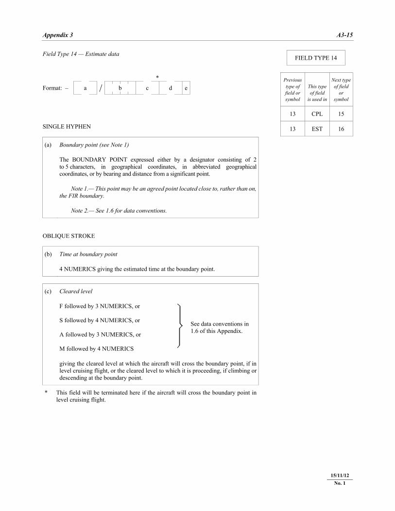
Appendix 3 A3-15
22/11/07
Field Type 14 — Estimate data
/ *
Format: – a b c d e
SINGLE HYPHEN
(a) Boundary point (see Note 1)
The BOUNDARY POINT expressed either by a designator consisting of 2 to 5 characters, in geographical coordinates, in abbreviated geographical coordinates, or by bearing and distance from a significant point.
Note 1.— This point may be an agreed point located close to, rather than on, the FIR boundary.
Note 2.— See 1.6 for data conventions.
OBLIQUE STROKE
(b) Time at boundary point
4 NUMERICS giving the estimated time at the boundary point.
(c) Cleared level
F followed by 3 NUMERICS, or S followed by 4 NUMERICS, or A followed by 3 NUMERICS, or M followed by 4 NUMERICS
See data conventions in 1.6 of this Appendix.
giving the cleared level at which the aircraft will cross the boundary point, if in level cruising flight, or the cleared level to which it is proceeding, if climbing or descending at the boundary point.
* This field will be terminated here if the aircraft will cross the boundary point in level cruising flight.
FIELD TYPE 14
Previous type of field or symbol
This type of field
is used in
Next typeof field
or symbol
13 CPL 15
13 EST 16
15/11/12 No. 1
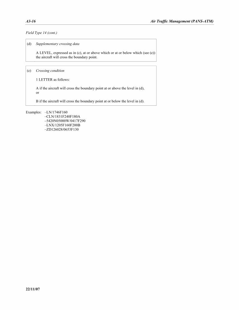
A3-16 Air Traffic Management (PANS-ATM)
22/11/07
Field Type 14 (cont.)
(d) Supplementary crossing data
A LEVEL, expressed as in (c), at or above which or at or below which (see (e)) the aircraft will cross the boundary point.
(e) Crossing condition
1 LETTER as follows: A if the aircraft will cross the boundary point at or above the level in (d), or B if the aircraft will cross the boundary point at or below the level in (d).
Examples: –LN/1746F160 –CLN/1831F240F180A –5420N05000W/0417F290 –LNX/1205F160F200B –ZD126028/0653F130
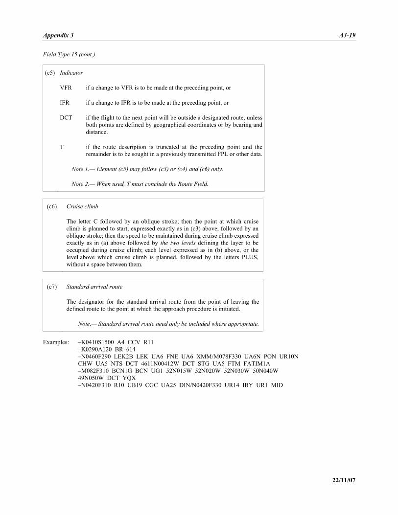
Appendix 3 A3-19
22/11/07
Field Type 15 (cont.)
(c5) Indicator
VFR if a change to VFR is to be made at the preceding point, or
IFR if a change to IFR is to be made at the preceding point, or
DCT if the flight to the next point will be outside a designated route, unless both points are defined by geographical coordinates or by bearing and distance.
T if the route description is truncated at the preceding point and the remainder is to be sought in a previously transmitted FPL or other data.
Note 1.— Element (c5) may follow (c3) or (c4) and (c6) only.
Note 2.— When used, T must conclude the Route Field.
(c6) Cruise climb
The letter C followed by an oblique stroke; then the point at which cruise climb is planned to start, expressed exactly as in (c3) above, followed by an oblique stroke; then the speed to be maintained during cruise climb expressed exactly as in (a) above followed by the two levels defining the layer to be occupied during cruise climb; each level expressed as in (b) above, or the level above which cruise climb is planned, followed by the letters PLUS, without a space between them.
(c7) Standard arrival route
The designator for the standard arrival route from the point of leaving the defined route to the point at which the approach procedure is initiated.
Note.— Standard arrival route need only be included where appropriate.
Examples: –K0410S1500 A4 CCV R11 –K0290A120 BR 614 –N0460F290 LEK2B LEK UA6 FNE UA6 XMM/M078F330 UA6N PON UR10N CHW UA5 NTS DCT 4611N00412W DCT STG UA5 FTM FATIM1A –M082F310 BCN1G BCN UG1 52N015W 52N020W 52N030W 50N040W 49N050W DCT YQX –N0420F310 R10 UB19 CGC UA25 DIN/N0420F330 UR14 IBY UR1 MID
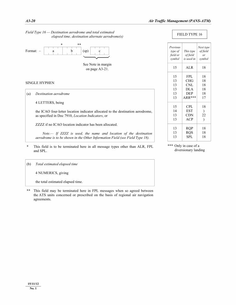
A3-20 Air Traffic Management (PANS-ATM)
22/11/07
Field Type 16 — Destination aerodrome and total estimated Field Type 16 — elapsed time, destination alternate aerodrome(s) * **
Format: – a b (sp) c
See Note in margin
on page A3-21. SINGLE HYPHEN
(a) Destination aerodrome
4 LETTERS, being
the ICAO four-letter location indicator allocated to the destination aerodrome, as specified in Doc 7910, Location Indicators, or
ZZZZ if no ICAO location indicator has been allocated.
Note.— If ZZZZ is used, the name and location of the destination aerodrome is to be shown in the Other Information Field (see Field Type 18).
* This field is to be terminated here in all message types other than ALR, FPL and SPL.
(b) Total estimated elapsed time
4 NUMERICS, giving
the total estimated elapsed time.
** This field may be terminated here in FPL messages when so agreed between the ATS units concerned or prescribed on the basis of regional air navigation agreements.
FIELD TYPE 16
Previous type of field or symbol
This type of field
is used in
Next typeof field
or symbol
15 ALR 18
15 13 13 13 13 13
FPL CHG CNL DLA DEP
ARR***
18 18 18 18 18 17
15 14 13 13
CPL EST CDN ACP
18 )
22 )
13 13 13
RQP RQS SPL
18 18 18
*** Only in case of a diversionary landing
15/11/12 No. 1
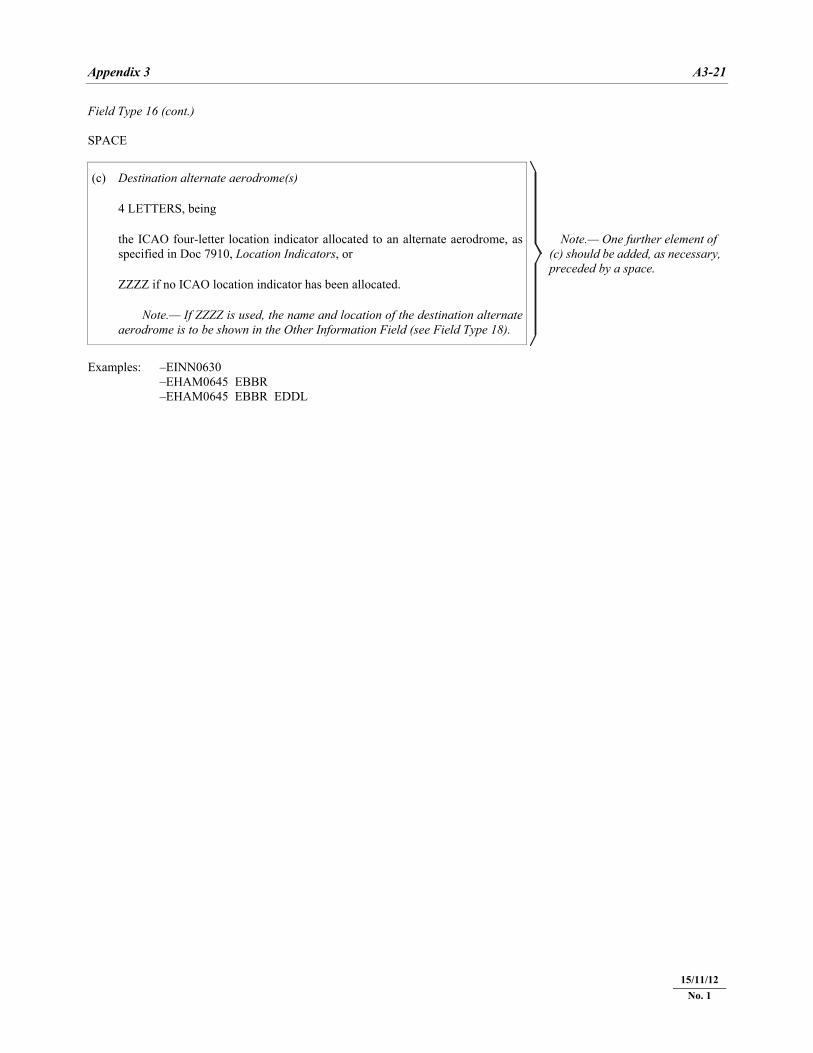
Appendix 3 A3-21
22/11/07
Field Type 16 (cont.) SPACE
(c) Destination alternate aerodrome(s)
Note.— One further element of (c) should be added, as necessary, preceded by a space.
4 LETTERS, being
the ICAO four-letter location indicator allocated to an alternate aerodrome, as specified in Doc 7910, Location Indicators, or
ZZZZ if no ICAO location indicator has been allocated.
Note.— If ZZZZ is used, the name and location of the destination alternate aerodrome is to be shown in the Other Information Field (see Field Type 18).
Examples: –EINN0630 –EHAM0645 EBBR –EHAM0645 EBBR EDDL
15/11/12 No. 1
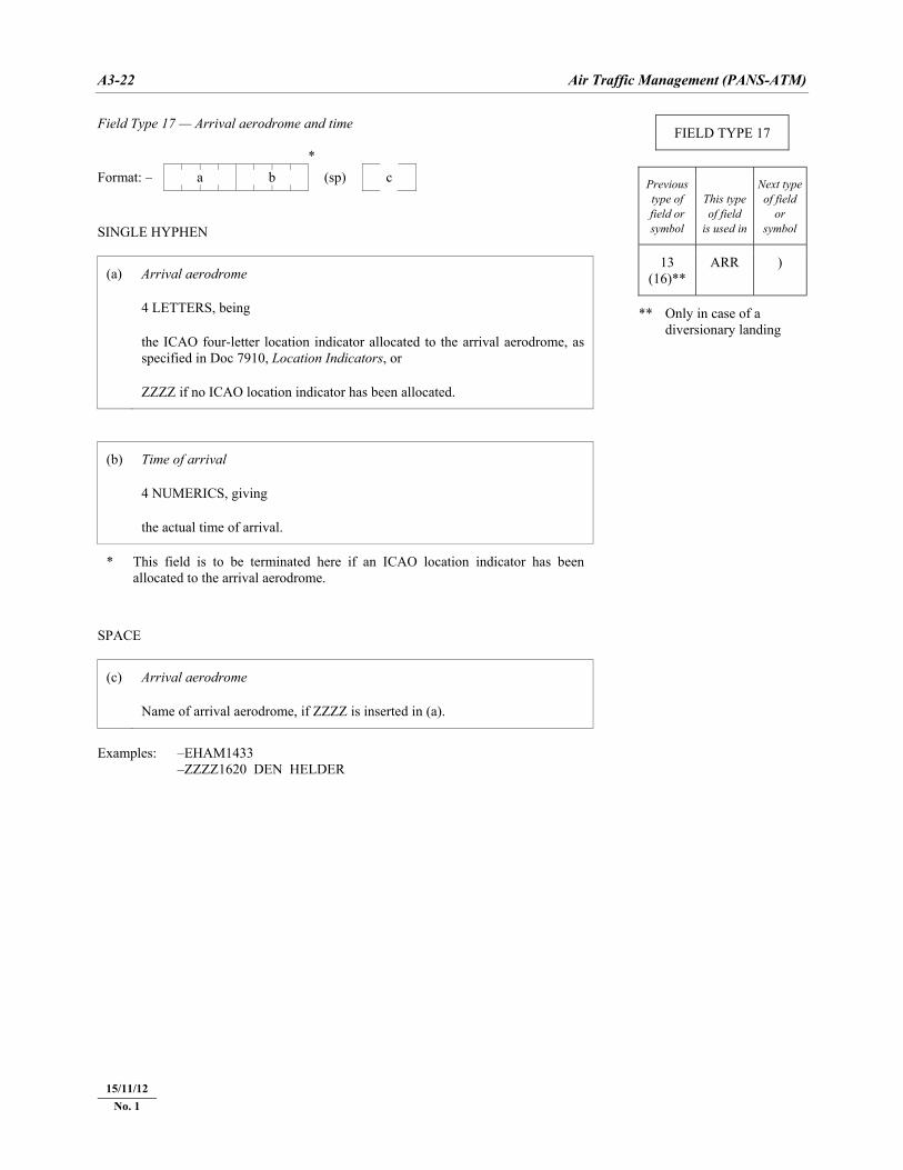
A3-22 Air Traffic Management (PANS-ATM)
22/11/07
Field Type 17 — Arrival aerodrome and time *
Format: – a b (sp) c
SINGLE HYPHEN
(a) Arrival aerodrome
4 LETTERS, being
the ICAO four-letter location indicator allocated to the arrival aerodrome, as specified in Doc 7910, Location Indicators, or
ZZZZ if no ICAO location indicator has been allocated.
(b) Time of arrival
4 NUMERICS, giving
the actual time of arrival.
* This field is to be terminated here if an ICAO location indicator has been allocated to the arrival aerodrome.
SPACE
(c) Arrival aerodrome
Name of arrival aerodrome, if ZZZZ is inserted in (a).
Examples: –EHAM1433 –ZZZZ1620 DEN HELDER
FIELD TYPE 17
Previous type of field or symbol
This type of field
is used in
Next typeof field
or symbol
13 (16)**
ARR )
** Only in case of a diversionary landing
15/11/12 No. 1
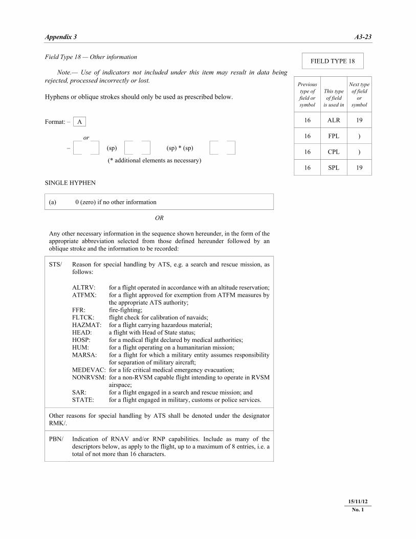
Appendix 3 A3-23
22/11/07
Field Type 18 — Other information Note.— Use of indicators not included under this item may result in data being rejected, processed incorrectly or lost. Hyphens or oblique strokes should only be used as prescribed below. Format: – A or
Format: – (sp) (sp) * (sp)
(* additional elements as necessary) SINGLE HYPHEN
(a) 0 (zero) if no other information
OR
Any other necessary information in the sequence shown hereunder, in the form of the appropriate abbreviation selected from those defined hereunder followed by an oblique stroke and the information to be recorded:
STS/ Reason for special handling by ATS, e.g. a search and rescue mission, as follows:
ALTRV: for a flight operated in accordance with an altitude reservation; ATFMX: for a flight approved for exemption from ATFM measures by
the appropriate ATS authority; FFR: fire-fighting; FLTCK: flight check for calibration of navaids; HAZMAT: for a flight carrying hazardous material; HEAD: a flight with Head of State status; HOSP: for a medical flight declared by medical authorities; HUM: for a flight operating on a humanitarian mission; MARSA: for a flight for which a military entity assumes responsibility
for separation of military aircraft; MEDEVAC: for a life critical medical emergency evacuation; NONRVSM: for a non-RVSM capable flight intending to operate in RVSM
airspace; SAR: for a flight engaged in a search and rescue mission; and STATE: for a flight engaged in military, customs or police services.
Other reasons for special handling by ATS shall be denoted under the designator RMK/.
PBN/ Indication of RNAV and/or RNP capabilities. Include as many of the descriptors below, as apply to the flight, up to a maximum of 8 entries, i.e. a total of not more than 16 characters.
FIELD TYPE 18
Previous type of field or symbol
This type of field
is used in
Next typeof field
or symbol
16 ALR 19
16 FPL )
16 CPL )
16 SPL 19
15/11/12 No. 1
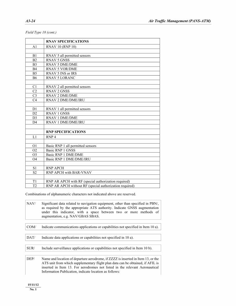
A3-24 Air Traffic Management (PANS-ATM)
22/11/07
Field Type 18 (cont.)
RNAV SPECIFICATIONS A1 RNAV 10 (RNP 10)
B1 RNAV 5 all permitted sensors B2 RNAV 5 GNSS B3 RNAV 5 DME/DME B4 RNAV 5 VOR/DME B5 RNAV 5 INS or IRS B6 RNAV 5 LORANC
C1 RNAV 2 all permitted sensors C2 RNAV 2 GNSS C3 RNAV 2 DME/DME C4 RNAV 2 DME/DME/IRU
D1 RNAV 1 all permitted sensors D2 RNAV 1 GNSS D3 RNAV 1 DME/DME D4 RNAV 1 DME/DME/IRU
RNP SPECIFICATIONS
L1 RNP 4
O1 Basic RNP 1 all permitted sensors O2 Basic RNP 1 GNSS O3 Basic RNP 1 DME/DME O4 Basic RNP 1 DME/DME/IRU
S1 RNP APCH S2 RNP APCH with BAR-VNAV
T1 RNP AR APCH with RF (special authorization required) T2 RNP AR APCH without RF (special authorization required)
Combinations of alphanumeric characters not indicated above are reserved. NAV/ Significant data related to navigation equipment, other than specified in PBN/,
as required by the appropriate ATS authority. Indicate GNSS augmentation under this indicator, with a space between two or more methods of augmentation, e.g. NAV/GBAS SBAS.
COM/ Indicate communications applications or capabilities not specified in Item 10 a).
DAT/ Indicate data applications or capabilities not specified in 10 a).
SUR/ Include surveillance applications or capabilities not specified in Item 10 b).
DEP/ Name and location of departure aerodrome, if ZZZZ is inserted in Item 13, or the
ATS unit from which supplementary flight plan data can be obtained, if AFIL is inserted in Item 13. For aerodromes not listed in the relevant Aeronautical Information Publication, indicate location as follows:
15/11/12 No. 1
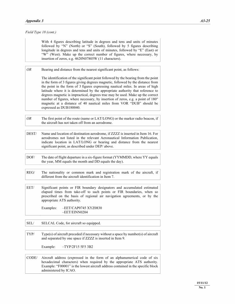
Appendix 3 A3-25
22/11/07
Field Type 18 (cont.) With 4 figures describing latitude in degrees and tens and units of minutes
followed by “N” (North) or “S” (South), followed by 5 figures describing longitude in degrees and tens and units of minutes, followed by “E” (East) or “W” (West). Make up the correct number of figures, where necessary, by insertion of zeros, e.g. 4620N07805W (11 characters).
OR Bearing and distance from the nearest significant point, as follows:
The identification of the significant point followed by the bearing from the point in the form of 3 figures giving degrees magnetic, followed by the distance from the point in the form of 3 figures expressing nautical miles. In areas of high latitude where it is determined by the appropriate authority that reference to degrees magnetic is impractical, degrees true may be used. Make up the correct number of figures, where necessary, by insertion of zeros, e.g. a point of 180° magnetic at a distance of 40 nautical miles from VOR “DUB” should be expressed as DUB180040.
OR The first point of the route (name or LAT/LONG) or the marker radio beacon, if
the aircraft has not taken off from an aerodrome. DEST/ Name and location of destination aerodrome, if ZZZZ is inserted in Item 16. For
aerodromes not listed in the relevant Aeronautical Information Publication, indicate location in LAT/LONG or bearing and distance from the nearest significant point, as described under DEP/ above.
DOF/ The date of flight departure in a six-figure format (YYMMDD, where YY equals
the year, MM equals the month and DD equals the day). REG/ The nationality or common mark and registration mark of the aircraft, if
different from the aircraft identification in Item 7. EET/ Significant points or FIR boundary designators and accumulated estimated
elapsed times from take-off to such points or FIR boundaries, when so prescribed on the basis of regional air navigation agreements, or by the appropriate ATS authority. Examples: –EET/CAP0745 XYZ0830 –EET/EINN0204
SEL/ SELCAL Code, for aircraft so equipped.
TYP/ Type(s) of aircraft preceded if necessary without a space by number(s) of aircraft
and separated by one space if ZZZZ is inserted in Item 9. Example: –TYP/2F15 5F5 3B2
CODE/ Aircraft address (expressed in the form of an alphanumerical code of six
hexadecimal characters) when required by the appropriate ATS authority. Example: “F00001” is the lowest aircraft address contained in the specific block administered by ICAO.
15/11/12 No. 1
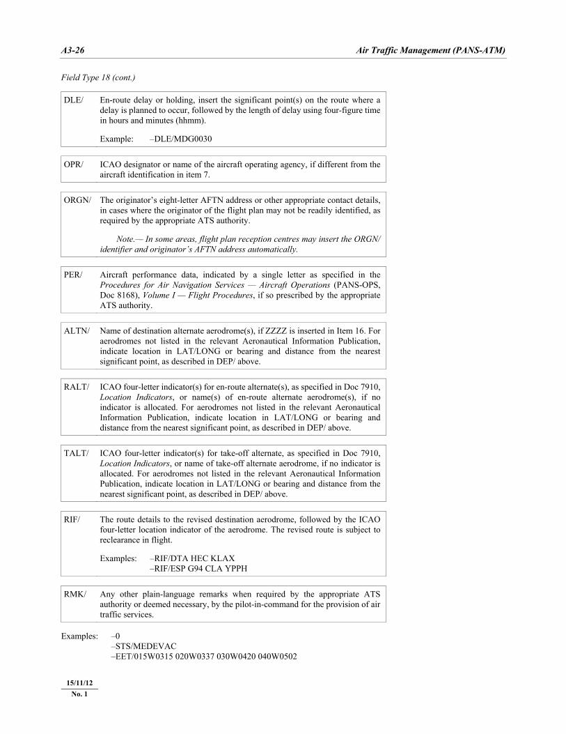
A3-26 Air Traffic Management (PANS-ATM)
22/11/07
Field Type 18 (cont.) DLE/ En-route delay or holding, insert the significant point(s) on the route where a
delay is planned to occur, followed by the length of delay using four-figure time in hours and minutes (hhmm). Example: –DLE/MDG0030
OPR/ ICAO designator or name of the aircraft operating agency, if different from the
aircraft identification in item 7. ORGN/ The originator’s eight-letter AFTN address or other appropriate contact details,
in cases where the originator of the flight plan may not be readily identified, as required by the appropriate ATS authority. Note.— In some areas, flight plan reception centres may insert the ORGN/ identifier and originator’s AFTN address automatically.
PER/ Aircraft performance data, indicated by a single letter as specified in the
Procedures for Air Navigation Services — Aircraft Operations (PANS-OPS, Doc 8168), Volume I — Flight Procedures, if so prescribed by the appropriate ATS authority.
ALTN/ Name of destination alternate aerodrome(s), if ZZZZ is inserted in Item 16. For
aerodromes not listed in the relevant Aeronautical Information Publication, indicate location in LAT/LONG or bearing and distance from the nearest significant point, as described in DEP/ above.
RALT/ ICAO four-letter indicator(s) for en-route alternate(s), as specified in Doc 7910,
Location Indicators, or name(s) of en-route alternate aerodrome(s), if no indicator is allocated. For aerodromes not listed in the relevant Aeronautical Information Publication, indicate location in LAT/LONG or bearing and distance from the nearest significant point, as described in DEP/ above.
TALT/ ICAO four-letter indicator(s) for take-off alternate, as specified in Doc 7910,
Location Indicators, or name of take-off alternate aerodrome, if no indicator is allocated. For aerodromes not listed in the relevant Aeronautical Information Publication, indicate location in LAT/LONG or bearing and distance from the nearest significant point, as described in DEP/ above.
RIF/ The route details to the revised destination aerodrome, followed by the ICAO
four-letter location indicator of the aerodrome. The revised route is subject to reclearance in flight. Examples: –RIF/DTA HEC KLAX –RIF/ESP G94 CLA YPPH
RMK/ Any other plain-language remarks when required by the appropriate ATS
authority or deemed necessary, by the pilot-in-command for the provision of air traffic services.
Examples: –0 –STS/MEDEVAC –EET/015W0315 020W0337 030W0420 040W0502
15/11/12 No. 1
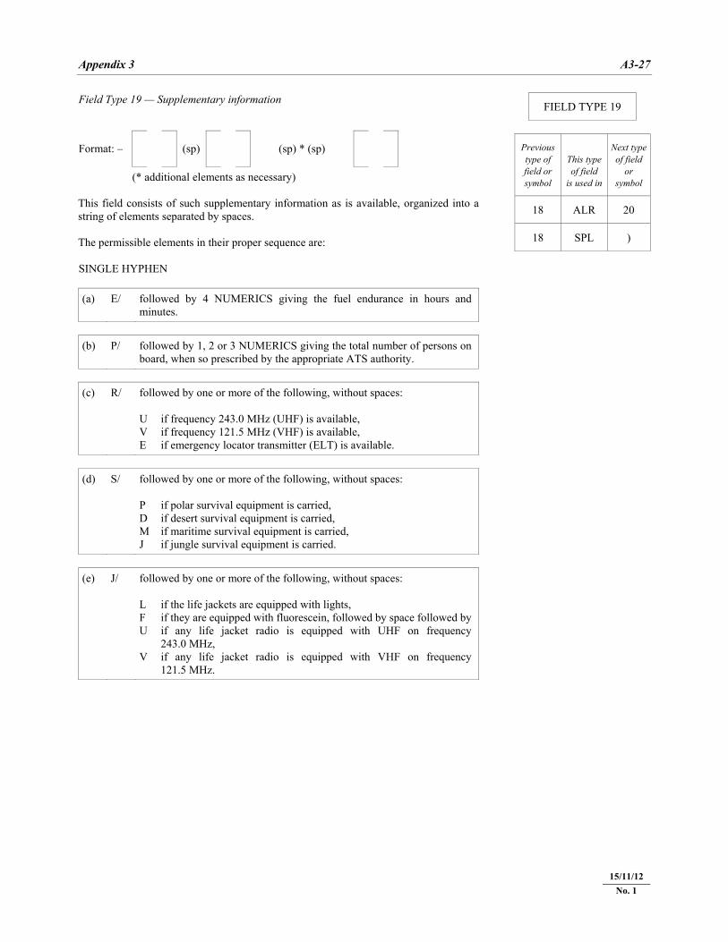
Appendix 3 A3-27
22/11/07
Field Type 19 — Supplementary information Format: – (sp) (sp) * (sp) (* additional elements as necessary) This field consists of such supplementary information as is available, organized into astring of elements separated by spaces. The permissible elements in their proper sequence are: SINGLE HYPHEN (a) E/ followed by 4 NUMERICS giving the fuel endurance in hours and
minutes. (b) P/ followed by 1, 2 or 3 NUMERICS giving the total number of persons on
board, when so prescribed by the appropriate ATS authority. (c) R/ followed by one or more of the following, without spaces:
U if frequency 243.0 MHz (UHF) is available, V if frequency 121.5 MHz (VHF) is available, E if emergency locator transmitter (ELT) is available.
(d) S/ followed by one or more of the following, without spaces:
P if polar survival equipment is carried, D if desert survival equipment is carried, M if maritime survival equipment is carried, J if jungle survival equipment is carried.
(e) J/ followed by one or more of the following, without spaces:
L if the life jackets are equipped with lights, F if they are equipped with fluorescein, followed by space followed by U if any life jacket radio is equipped with UHF on frequency
243.0 MHz, V if any life jacket radio is equipped with VHF on frequency
121.5 MHz.
FIELD TYPE 19
Previous type of field or symbol
This type of field
is used in
Next typeof field
or symbol
18 ALR 20
18 SPL )
15/11/12 No. 1
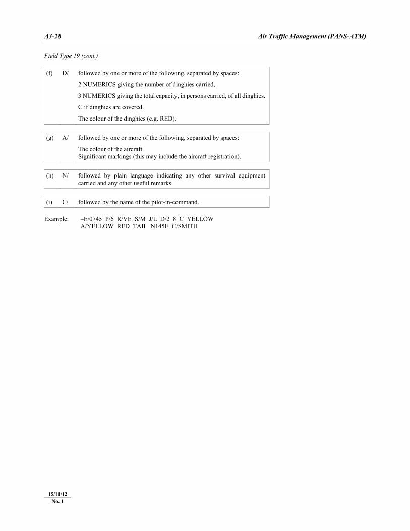
A3-28 Air Traffic Management (PANS-ATM)
22/11/07
Field Type 19 (cont.) (f) D/ followed by one or more of the following, separated by spaces:
2 NUMERICS giving the number of dinghies carried,
3 NUMERICS giving the total capacity, in persons carried, of all dinghies.
C if dinghies are covered.
The colour of the dinghies (e.g. RED). (g) A/ followed by one or more of the following, separated by spaces:
The colour of the aircraft. Significant markings (this may include the aircraft registration).
(h) N/ followed by plain language indicating any other survival equipment
carried and any other useful remarks. (i) C/ followed by the name of the pilot-in-command.
Example: –E/0745 P/6 R/VE S/M J/L D/2 8 C YELLOW A/YELLOW RED TAIL N145E C/SMITH
15/11/12 No. 1
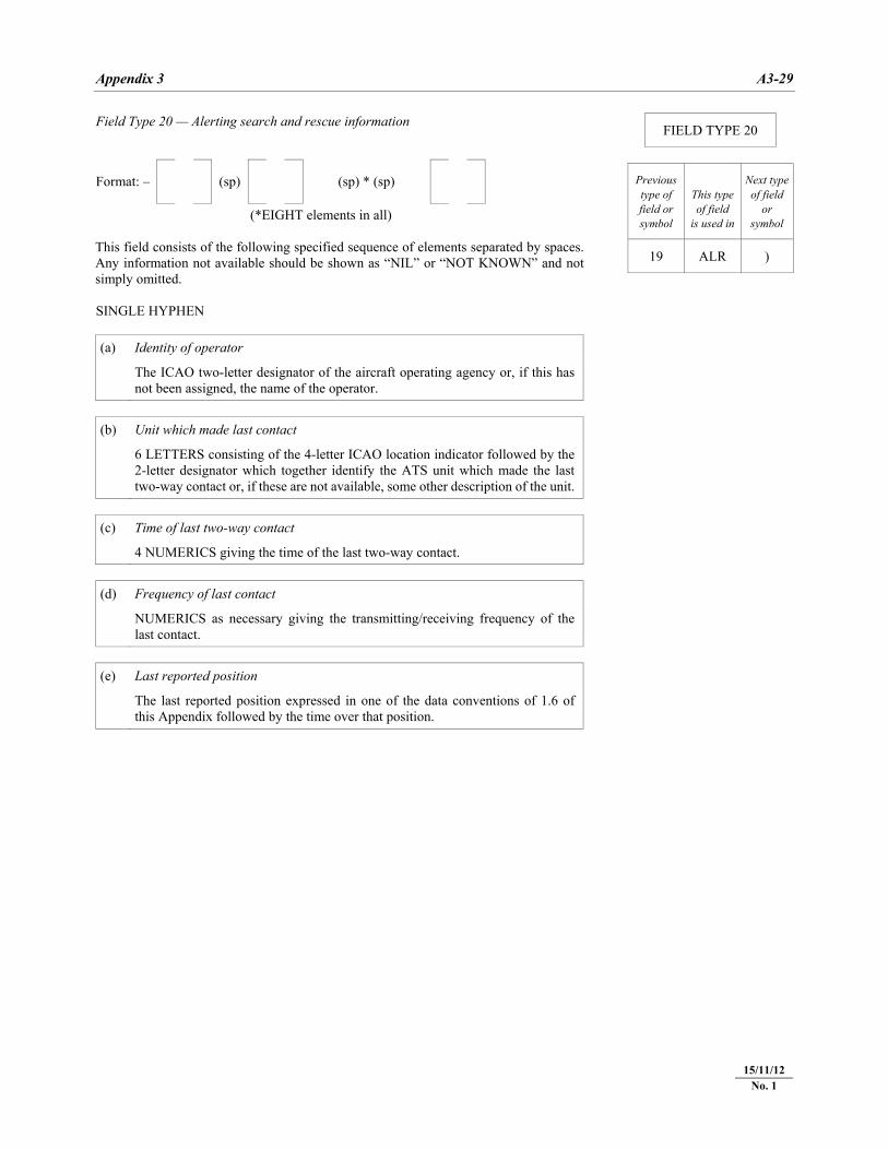
Appendix 3 A3-29
22/11/07
Field Type 20 — Alerting search and rescue information Format: – (sp) (sp) * (sp) (*EIGHT elements in all) This field consists of the following specified sequence of elements separated by spaces.Any information not available should be shown as “NIL” or “NOT KNOWN” and notsimply omitted. SINGLE HYPHEN (a) Identity of operator
The ICAO two-letter designator of the aircraft operating agency or, if this has not been assigned, the name of the operator.
(b) Unit which made last contact
6 LETTERS consisting of the 4-letter ICAO location indicator followed by the 2-letter designator which together identify the ATS unit which made the last two-way contact or, if these are not available, some other description of the unit.
(c) Time of last two-way contact
4 NUMERICS giving the time of the last two-way contact. (d) Frequency of last contact
NUMERICS as necessary giving the transmitting/receiving frequency of the last contact.
(e) Last reported position
The last reported position expressed in one of the data conventions of 1.6 of this Appendix followed by the time over that position.
FIELD TYPE 20
Previous type of field or symbol
This type of field
is used in
Next typeof field
or symbol
19 ALR )
15/11/12 No. 1
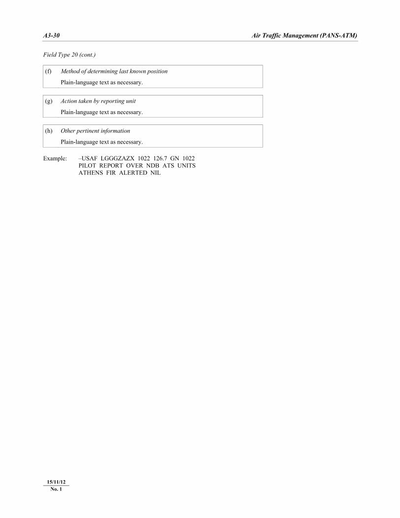
A3-30 Air Traffic Management (PANS-ATM)
22/11/07
Field Type 20 (cont.) (f) Method of determining last known position
Plain-language text as necessary. (g) Action taken by reporting unit
Plain-language text as necessary. (h) Other pertinent information
Plain-language text as necessary. Example: –USAF LGGGZAZX 1022 126.7 GN 1022 PILOT REPORT OVER NDB ATS UNITS ATHENS FIR ALERTED NIL
15/11/12 No. 1
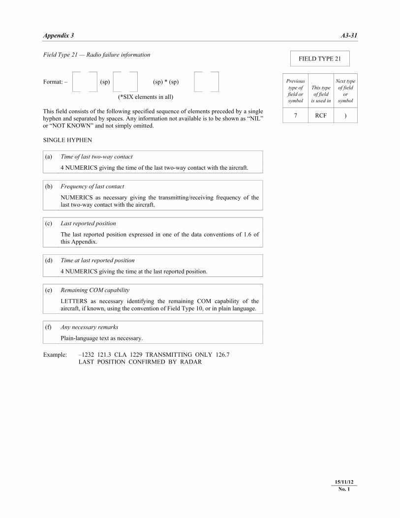
Appendix 3 A3-31
22/11/07
Field Type 21 — Radio failure information Format: – (sp) (sp) * (sp) (*SIX elements in all) This field consists of the following specified sequence of elements preceded by a singlehyphen and separated by spaces. Any information not available is to be shown as “NIL”or “NOT KNOWN” and not simply omitted. SINGLE HYPHEN (a) Time of last two-way contact
4 NUMERICS giving the time of the last two-way contact with the aircraft. (b) Frequency of last contact
NUMERICS as necessary giving the transmitting/receiving frequency of the last two-way contact with the aircraft.
(c) Last reported position
The last reported position expressed in one of the data conventions of 1.6 of this Appendix.
(d) Time at last reported position
4 NUMERICS giving the time at the last reported position. (e) Remaining COM capability
LETTERS as necessary identifying the remaining COM capability of the aircraft, if known, using the convention of Field Type 10, or in plain language.
(f) Any necessary remarks
Plain-language text as necessary. Example: –1232 121.3 CLA 1229 TRANSMITTING ONLY 126.7 LAST POSITION CONFIRMED BY RADAR
FIELD TYPE 21
Previous type of field or symbol
This type of field
is used in
Next typeof field
or symbol
7 RCF )
15/11/12 No. 1
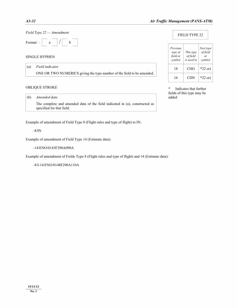
A3-32 Air Traffic Management (PANS-ATM)
22/11/07
Field Type 22 — Amendment /
Format: – a b
SINGLE HYPHEN (a) Field indicator
ONE OR TWO NUMERICS giving the type number of the field to be amended. OBLIQUE STROKE (b) Amended data
The complete and amended data of the field indicated in (a), constructed as specified for that field.
Example of amendment of Field Type 8 (Flight rules and type of flight) to IN: –8/IN Example of amendment of Field Type 14 (Estimate data): –14/ENO/0145F290A090A Example of amendment of Fields Type 8 (Flight rules and type of flight) and 14 (Estimate data): –8/I-14/ENO/0148F290A110A
FIELD TYPE 22
Previous type of field or symbol
This type of field
is used in
Next typeof field
or symbol
18 CHG *22 or)
16 CDN *22 or)
* Indicates that further fields of this type may be added
15/11/12 No. 1
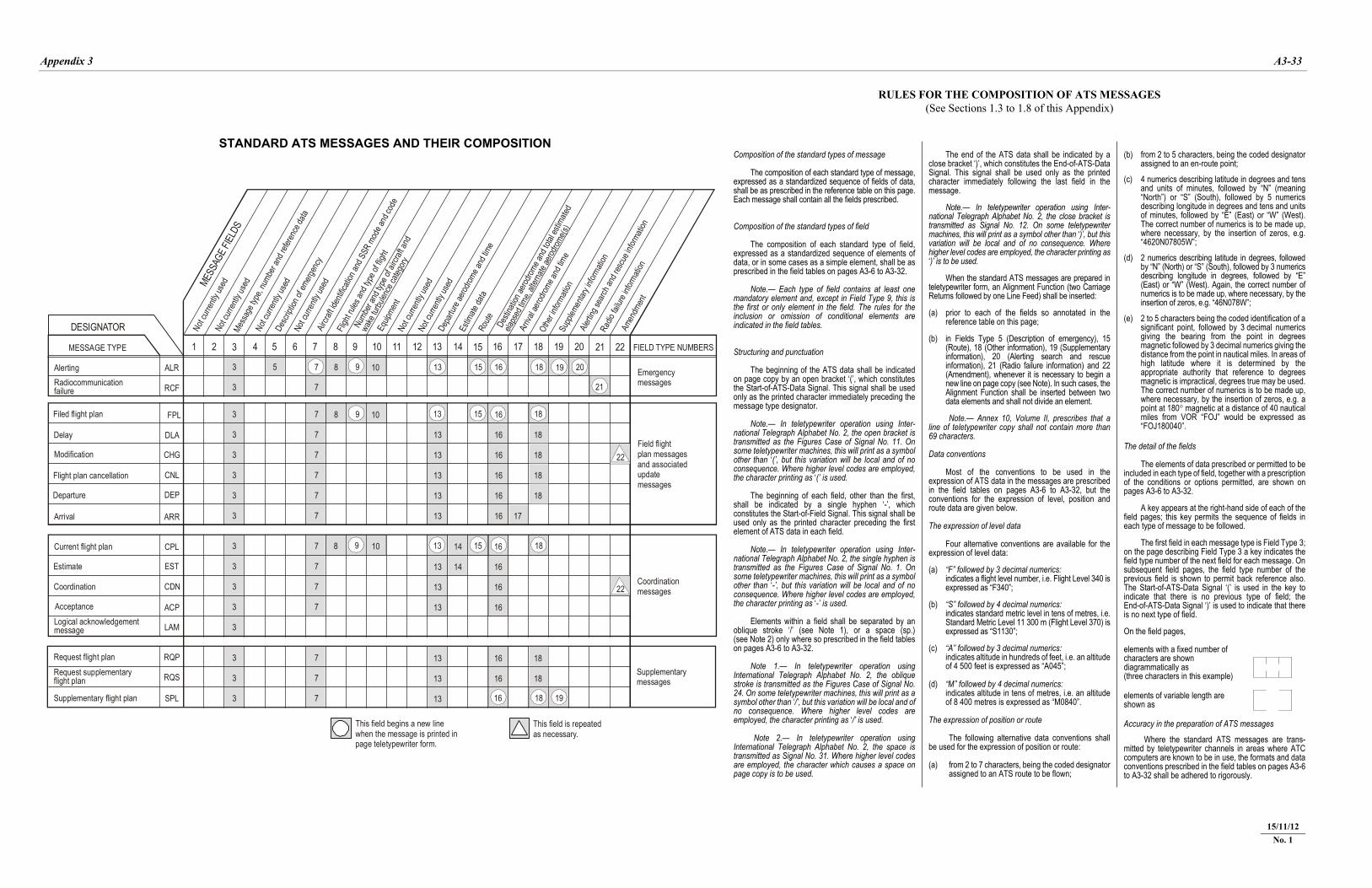
Appendix 3 A3-33
22/11/07
RULES FOR THE COMPOSITION OF ATS MESSAGES (See Sections 1.3 to 1.8 of this Appendix)
Composition of the standard types of message The composition of each standard type of message, expressed as a standardized sequence of fields of data, shall be as prescribed in the reference table on this page. Each message shall contain all the fields prescribed. Composition of the standard types of field The composition of each standard type of field, expressed as a standardized sequence of elements of data, or in some cases as a simple element, shall be as prescribed in the field tables on pages A3-6 to A3-32. Note.— Each type of field contains at least one mandatory element and, except in Field Type 9, this is the first or only element in the field. The rules for the inclusion or omission of conditional elements are indicated in the field tables. Structuring and punctuation The beginning of the ATS data shall be indicated on page copy by an open bracket ‘(’, which constitutes the Start-of-ATS-Data Signal. This signal shall be used only as the printed character immediately preceding the message type designator. Note.— In teletypewriter operation using Inter-national Telegraph Alphabet No. 2, the open bracket is transmitted as the Figures Case of Signal No. 11. On some teletypewriter machines, this will print as a symbol other than ‘(’, but this variation will be local and of no consequence. Where higher level codes are employed, the character printing as ‘(’ is used. The beginning of each field, other than the first, shall be indicated by a single hyphen ‘-’, which constitutes the Start-of-Field Signal. This signal shall be used only as the printed character preceding the first element of ATS data in each field. Note.— In teletypewriter operation using Inter-national Telegraph Alphabet No. 2, the single hyphen is transmitted as the Figures Case of Signal No. 1. On some teletypewriter machines, this will print as a symbol other than ‘-’, but this variation will be local and of no consequence. Where higher level codes are employed, the character printing as ‘-’ is used. Elements within a field shall be separated by an oblique stroke ‘/’ (see Note 1), or a space (sp.) (see Note 2) only where so prescribed in the field tables on pages A3-6 to A3-32. Note 1.— In teletypewriter operation using International Telegraph Alphabet No. 2, the oblique stroke is transmitted as the Figures Case of Signal No. 24. On some teletypewriter machines, this will print as a symbol other than ‘/’, but this variation will be local and of no consequence. Where higher level codes are employed, the character printing as ‘/’ is used. Note 2.— In teletypewriter operation using International Telegraph Alphabet No. 2, the space is transmitted as Signal No. 31. Where higher level codes are employed, the character which causes a space on page copy is to be used.
The end of the ATS data shall be indicated by a close bracket ‘)’, which constitutes the End-of-ATS-Data Signal. This signal shall be used only as the printed character immediately following the last field in the message. Note.— In teletypewriter operation using Inter-national Telegraph Alphabet No. 2, the close bracket is transmitted as Signal No. 12. On some teletypewriter machines, this will print as a symbol other than ‘)’, but this variation will be local and of no consequence. Where higher level codes are employed, the character printing as ‘)’ is to be used. When the standard ATS messages are prepared in teletypewriter form, an Alignment Function (two Carriage Returns followed by one Line Feed) shall be inserted: (a) prior to each of the fields so annotated in the
reference table on this page; (b) in Fields Type 5 (Description of emergency), 15
(Route), 18 (Other information), 19 (Supplementary information), 20 (Alerting search and rescue information), 21 (Radio failure information) and 22 (Amendment), whenever it is necessary to begin a new line on page copy (see Note). In such cases, the Alignment Function shall be inserted between two data elements and shall not divide an element.
Note.— Annex 10, Volume II, prescribes that a line of teletypewriter copy shall not contain more than 69 characters. Data conventions Most of the conventions to be used in the expression of ATS data in the messages are prescribed in the field tables on pages A3-6 to A3-32, but the conventions for the expression of level, position and route data are given below. The expression of level data Four alternative conventions are available for the expression of level data: (a) “F” followed by 3 decimal numerics: indicates a flight level number, i.e. Flight Level 340 is
expressed as “F340”; (b) “S” followed by 4 decimal numerics: indicates standard metric level in tens of metres, i.e.
Standard Metric Level 11 300 m (Flight Level 370) is expressed as “S1130”;
(c) “A” followed by 3 decimal numerics: indicates altitude in hundreds of feet, i.e. an altitude
of 4 500 feet is expressed as “A045”; (d) “M” followed by 4 decimal numerics: indicates altitude in tens of metres, i.e. an altitude
of 8 400 metres is expressed as “M0840”. The expression of position or route The following alternative data conventions shall be used for the expression of position or route: (a) from 2 to 7 characters, being the coded designator
assigned to an ATS route to be flown;
(b) from 2 to 5 characters, being the coded designator assigned to an en-route point;
(c) 4 numerics describing latitude in degrees and tens
and units of minutes, followed by “N” (meaning “North”) or “S” (South), followed by 5 numerics describing longitude in degrees and tens and units of minutes, followed by “E” (East) or “W” (West). The correct number of numerics is to be made up, where necessary, by the insertion of zeros, e.g. “4620N07805W”;
(d) 2 numerics describing latitude in degrees, followed
by “N” (North) or “S” (South), followed by 3 numerics describing longitude in degrees, followed by “E” (East) or “W” (West). Again, the correct number of numerics is to be made up, where necessary, by the insertion of zeros, e.g. “46N078W”;
(e) 2 to 5 characters being the coded identification of a
significant point, followed by 3 decimal numerics giving the bearing from the point in degrees magnetic followed by 3 decimal numerics giving the distance from the point in nautical miles. In areas of high latitude where it is determined by the appropriate authority that reference to degrees magnetic is impractical, degrees true may be used. The correct number of numerics is to be made up, where necessary, by the insertion of zeros, e.g. a point at 180° magnetic at a distance of 40 nautical miles from VOR “FOJ” would be expressed as “FOJ180040”.
The detail of the fields The elements of data prescribed or permitted to be included in each type of field, together with a prescription of the conditions or options permitted, are shown on pages A3-6 to A3-32. A key appears at the right-hand side of each of the field pages; this key permits the sequence of fields in each type of message to be followed. The first field in each message type is Field Type 3; on the page describing Field Type 3 a key indicates the field type number of the next field for each message. On subsequent field pages, the field type number of the previous field is shown to permit back reference also. The Start-of-ATS-Data Signal ‘(’ is used in the key to indicate that there is no previous type of field; the End-of-ATS-Data Signal ‘)’ is used to indicate that there is no next type of field. On the field pages, elements with a fixed number of characters are shown diagrammatically as (three characters in this example)
elements of variable length are shown as Accuracy in the preparation of ATS messages Where the standard ATS messages are trans-mitted by teletypewriter channels in areas where ATC computers are known to be in use, the formats and data conventions prescribed in the field tables on pages A3-6 to A3-32 shall be adhered to rigorously.
STANDARD ATS MESSAGES AND THEIR COMPOSITION
15/11/12 No. 1
9 13
13
13
13
13 14
13
13
13
14
13
13
13
13
13
13
15 16
16
16
16
16
16 17
15 18
18 19
9 16
16
16
16
16
16
16
18
15 16
21
18 19 203 5
3
3
3
3
3
3 7
7
7
3
3
3
3
3
3 7
7
7
7 8 10
7
7
7
7
7
3
3
3 7
7
7
9
8
8
10
10
Desti
natio
n aero
drome
and t
otal e
stima
ted
elaps
ed tim
e, alt
ernate
aerod
rome(s
)
FIELD TYPE NUMBERS
Supplementarymessages
Coordinationmessages
Field flightplan messagesand associatedupdatemessages
Emergencymessages
22
22
Amen
dmen
t
Radio
failu
re inf
ormati
on
Alertin
g sea
rch an
d res
cue i
nform
ation
DESIGNATOR
MESSAGE TYPE
AlertingRadiocommunicationfailure
Filed flight plan
Delay
Modification
Flight plan cancellation
Departure
Arrival
Current flight plan
Estimate
Coordination
AcceptanceLogical acknowledgementmessage
Request flight planRequest supplementaryflight plan
Supplementary flight plan
Supp
lemen
tary i
nform
ation
Othe
r infor
matio
n
Arriv
al ae
rodrom
e and
time
Depa
rture
aerod
rome a
nd tim
eRo
ute
Estim
ate da
ta
This field is repeatedas necessary.
This field begins a new linewhen the message is printed inpage teletypewriter form.
Not c
urren
tly us
ed
Not c
urren
tly us
ed
Not c
urren
tly us
ed
Not c
urren
tly us
ed
Not c
urren
tly us
ed
Equip
ment
Numb
er an
d typ
e of a
ircraf
t and
wake
turbu
lence
categ
ory
Fligh
t rules
and t
ype o
f fligh
t
Aircra
ft ide
ntific
ation
and S
SR m
ode a
nd co
de
Not c
urren
tly us
ed
Desc
riptio
n of e
mergen
cy
Mess
age t
ype,
numb
er an
d refe
rence
data
MESS
AGE F
IELDS
ALR
RCF
FPL
DLA
CHG
CNL
DEP
ARR
CPL
EST
CDN
ACP
LAM
RQP
RQS
SPL
1 2 3 4 5 6 7 8 9 10 11 12 13 14 15 16 17 18 19 20 21 22
18
18
18
18
18
18
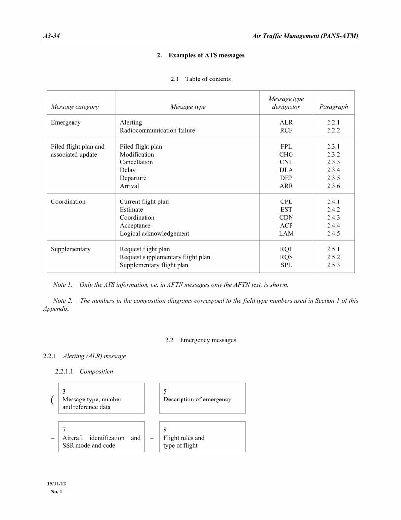
A3-34 Air Traffic Management (PANS-ATM)
22/11/07
2. Examples of ATS messages
2.1 Table of contents
Message category Message type Message type
designator Paragraph
Emergency Alerting Radiocommunication failure
ALR RCF
2.2.1 2.2.2
Filed flight plan and associated update
Filed flight plan Modification Cancellation Delay Departure Arrival
FPL CHG CNL DLA DEP ARR
2.3.1 2.3.2 2.3.3 2.3.4 2.3.5 2.3.6
Coordination Current flight plan Estimate Coordination Acceptance Logical acknowledgement
CPL EST CDN ACP LAM
2.4.1 2.4.2 2.4.3 2.4.4 2.4.5
Supplementary Request flight plan Request supplementary flight plan Supplementary flight plan
RQP RQS SPL
2.5.1 2.5.2 2.5.3
Note 1.— Only the ATS information, i.e. in AFTN messages only the AFTN text, is shown. Note 2.— The numbers in the composition diagrams correspond to the field type numbers used in Section 1 of this Appendix.
2.2 Emergency messages 2.2.1 Alerting (ALR) message 2.2.1.1 Composition
( 3 Message type, number and reference data
– 5 Description of emergency
– 7 Aircraft identification and SSR mode and code
– 8 Flight rules and type of flight
15/11/12 No. 1
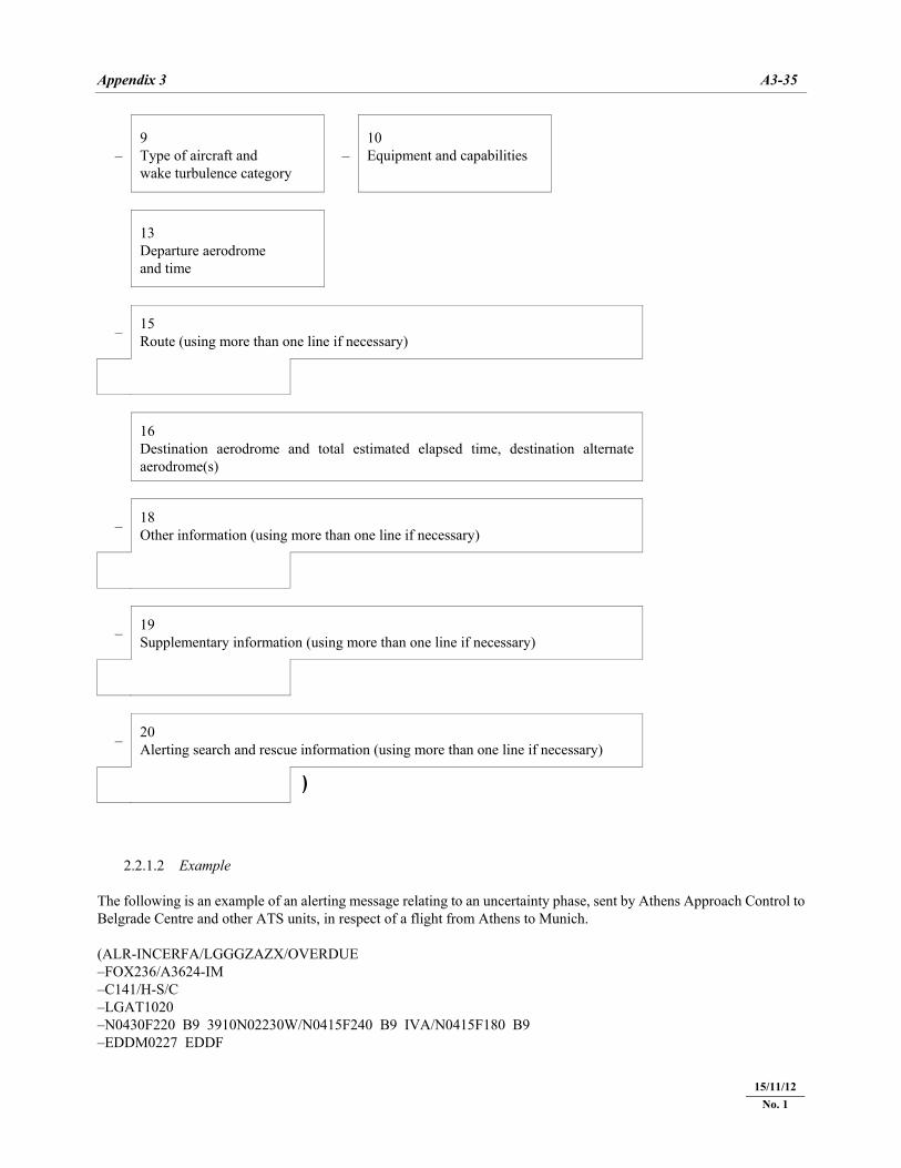
Appendix 3 A3-35
22/11/07
– 9 Type of aircraft and wake turbulence category
– 10 Equipment and capabilities
13 Departure aerodrome and time
– 15 Route (using more than one line if necessary)
16 Destination aerodrome and total estimated elapsed time, destination alternate aerodrome(s)
– 18 Other information (using more than one line if necessary)
– 19 Supplementary information (using more than one line if necessary)
– 20 Alerting search and rescue information (using more than one line if necessary)
)
2.2.1.2 Example The following is an example of an alerting message relating to an uncertainty phase, sent by Athens Approach Control to Belgrade Centre and other ATS units, in respect of a flight from Athens to Munich. (ALR-INCERFA/LGGGZAZX/OVERDUE –FOX236/A3624-IM –C141/H-S/C –LGAT1020 –N0430F220 B9 3910N02230W/N0415F240 B9 IVA/N0415F180 B9 –EDDM0227 EDDF
15/11/12 No. 1
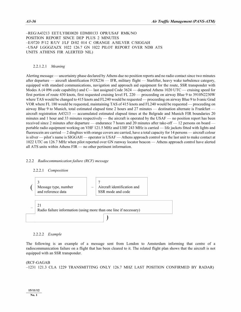
A3-36 Air Traffic Management (PANS-ATM)
22/11/07
–REG/A43213 EET/LYBE0020 EDMI0133 OPR/USAF RMK/NO POSITION REPORT SINCE DEP PLUS 2 MINUTES –E/0720 P/12 R/UV J/LF D/02 014 C ORANGE A/SILVER C/SIGGAH –USAF LGGGZAZX 1022 126.7 GN 1022 PILOT REPORT OVER NDB ATS UNITS ATHENS FIR ALERTED NIL) 2.2.1.2.1 Meaning Alerting message — uncertainty phase declared by Athens due no position reports and no radio contact since two minutes after departure — aircraft identification FOX236 — IFR, military flight — Starlifter, heavy wake turbulence category, equipped with standard communications, navigation and approach aid equipment for the route, SSR transponder with Modes A (4 096 code capability) and C— last assigned Code 3624 — departed Athens 1020 UTC — cruising speed for first portion of route 430 knots, first requested cruising level FL 220 — proceeding on airway Blue 9 to 3910N2230W where TAS would be changed to 415 knots and FL240 would be requested — proceeding on airway Blue 9 to Ivanic Grad VOR where FL 180 would be requested, maintaining TAS of 415 knots and FL240 would be requested — proceeding on airway Blue 9 to Munich, total estimated elapsed time 2 hours and 27 minutes — destination alternate is Frankfurt — aircraft registration A43213 — accumulated estimated elapsed times at the Belgrade and Munich FIR boundaries 20 minutes and 1 hour and 33 minutes respectively — the aircraft is operated by the USAF — no position report has been received since 2 minutes after departure — endurance 7 hours and 20 minutes after take-off — 12 persons on board — portable radio equipment working on VHF 121.5 MHz and UHF 243 MHz is carried — life jackets fitted with lights and fluorescein are carried — 2 dinghies with orange covers are carried, have a total capacity for 14 persons — aircraft colour is silver — pilot’s name is SIGGAH — operator is USAF — Athens approach control was the last unit to make contact at 1022 UTC on 126.7 MHz when pilot reported over GN runway locator beacon — Athens approach control have alerted all ATS units within Athens FIR — no other pertinent information. 2.2.2 Radiocommunication failure (RCF) message 2.2.2.1 Composition
( 3 Message type, number and reference data
– 7 Aircraft identification and SSR mode and code
– 21 Radio failure information (using more than one line if necessary)
) 2.2.2.2 Example The following is an example of a message sent from London to Amsterdam informing that centre of a radiocommunication failure on a flight that has been cleared to it. The related flight plan shows that the aircraft is not equipped with an SSR transponder. (RCF-GAGAB –1231 121.3 CLA 1229 TRANSMITTING ONLY 126.7 MHZ LAST POSITION CONFIRMED BY RADAR)
15/11/12 No. 1
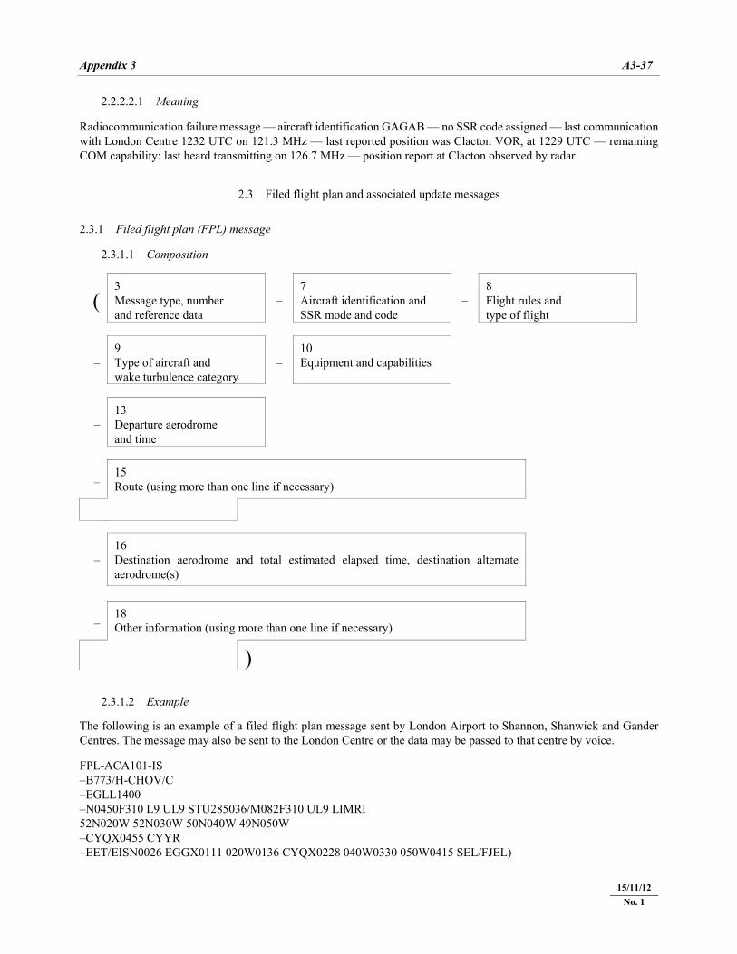
Appendix 3 A3-37
22/11/07
2.2.2.2.1 Meaning Radiocommunication failure message — aircraft identification GAGAB — no SSR code assigned — last communication with London Centre 1232 UTC on 121.3 MHz — last reported position was Clacton VOR, at 1229 UTC — remaining COM capability: last heard transmitting on 126.7 MHz — position report at Clacton observed by radar.
2.3 Filed flight plan and associated update messages 2.3.1 Filed flight plan (FPL) message 2.3.1.1 Composition
( 3 Message type, number and reference data
– 7 Aircraft identification and SSR mode and code
– 8 Flight rules and type of flight
– 9 Type of aircraft and wake turbulence category
– 10 Equipment and capabilities
– 13 Departure aerodrome and time
– 15 Route (using more than one line if necessary)
– 16 Destination aerodrome and total estimated elapsed time, destination alternate aerodrome(s)
– 18 Other information (using more than one line if necessary)
) 2.3.1.2 Example The following is an example of a filed flight plan message sent by London Airport to Shannon, Shanwick and Gander Centres. The message may also be sent to the London Centre or the data may be passed to that centre by voice. FPL-ACA101-IS –B773/H-CHOV/C –EGLL1400 –N0450F310 L9 UL9 STU285036/M082F310 UL9 LIMRI 52N020W 52N030W 50N040W 49N050W –CYQX0455 CYYR –EET/EISN0026 EGGX0111 020W0136 CYQX0228 040W0330 050W0415 SEL/FJEL)
15/11/12 No. 1
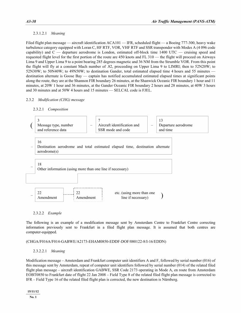
A3-38 Air Traffic Management (PANS-ATM)
22/11/07
2.3.1.2.1 Meaning Filed flight plan message — aircraft identification ACA101 — IFR, scheduled flight — a Boeing 777-300, heavy wake turbulence category equipped with Loran C, HF RTF, VOR, VHF RTF and SSR transponder with Modes A (4 096 code capability) and C — departure aerodrome is London, estimated off-block time 1400 UTC — cruising speed and requested flight level for the first portion of the route are 450 knots and FL 310 — the flight will proceed on Airways Lima 9 and Upper Lima 9 to a point bearing 285 degrees magnetic and 36 NM from the Strumble VOR. From this point the flight will fly at a constant Mach number of .82, proceeding on Upper Lima 9 to LIMRI; then to 52N20W; to 52N30W; to 50N40W; to 49N50W; to destination Gander, total estimated elapsed time 4 hours and 55 minutes — destination alternate is Goose Bay — captain has notified accumulated estimated elapsed times at significant points along the route, they are at the Shannon FIR boundary 26 minutes, at the Shanwick Oceanic FIR boundary 1 hour and 11 minutes, at 20W 1 hour and 36 minutes, at the Gander Oceanic FIR boundary 2 hours and 28 minutes, at 40W 3 hours and 30 minutes and at 50W 4 hours and 15 minutes — SELCAL code is FJEL. 2.3.2 Modification (CHG) message 2.3.2.1 Composition
( 3 Message type, number and reference data
– 7 Aircraft identification and SSR mode and code
– 13 Departure aerodrome and time
– 16 Destination aerodrome and total estimated elapsed time, destination alternate aerodrome(s)
– 18 Other information (using more than one line if necessary)
– 22 Amendment
22 Amendment
etc. (using more than one line if necessary) )
2.3.2.2 Example The following is an example of a modification message sent by Amsterdam Centre to Frankfurt Centre correcting information previously sent to Frankfurt in a filed flight plan message. It is assumed that both centres are computer-equipped. (CHGA/F016A/F014-GABWE/A2173-EHAM0850-EDDF-DOF/080122-8/I-16/EDDN) 2.3.2.2.1 Meaning Modification message – Amsterdam and Frankfurt computer unit identifiers A and F, followed by serial number (016) of this message sent by Amsterdam, repeat of computer unit identifiers followed by serial number (014) of the related filed flight plan message – aircraft identification GABWE, SSR Code 2173 operating in Mode A, en route from Amsterdam EOBT0850 to Frankfurt date of flight 22 Jan 2008 – Field Type 8 of the related filed flight plan message is corrected to IFR – Field Type 16 of the related filed flight plan is corrected, the new destination is Nürnberg.
15/11/12
No. 1
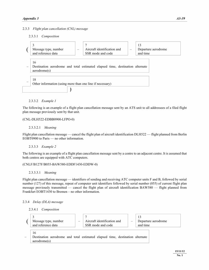
Appendix 3 A3-39
22/11/07
2.3.3 Flight plan cancellation (CNL) message 2.3.3.1 Composition
( 3 Message type, number and reference data
– 7 Aircraft identification and SSR mode and code
– 13 Departure aerodrome and time
– 16 Destination aerodrome and total estimated elapsed time, destination alternate aerodrome(s)
– 18 Other information (using more than one line if necessary)
) 2.3.3.2 Example 1 The following is an example of a flight plan cancellation message sent by an ATS unit to all addressees of a filed flight plan message previously sent by that unit. (CNL-DLH522-EDBB0900-LFPO-0) 2.3.3.2.1 Meaning Flight plan cancellation message — cancel the flight plan of aircraft identification DLH522 — flight planned from Berlin EOBT0900 to Paris — no other information. 2.3.3.3 Example 2 The following is an example of a flight plan cancellation message sent by a centre to an adjacent centre. It is assumed that both centres are equipped with ATC computers. (CNLF/B127F/B055-BAW580-EDDF1430-EDDW-0) 2.3.3.3.1 Meaning Flight plan cancellation message — identifiers of sending and receiving ATC computer units F and B, followed by serial number (127) of this message, repeat of computer unit identifiers followed by serial number (055) of current flight plan message previously transmitted — cancel the flight plan of aircraft identification BAW580 — flight planned from Frankfurt EOBT1430 to Bremen – no other information. 2.3.4 Delay (DLA) message 2.3.4.1 Composition
( 3 Message type, number and reference data
– 7 Aircraft identification and SSR mode and code
– 13 Departure aerodrome and time
– 16 Destination aerodrome and total estimated elapsed time, destination alternate aerodrome(s)
15/11/12 No. 1
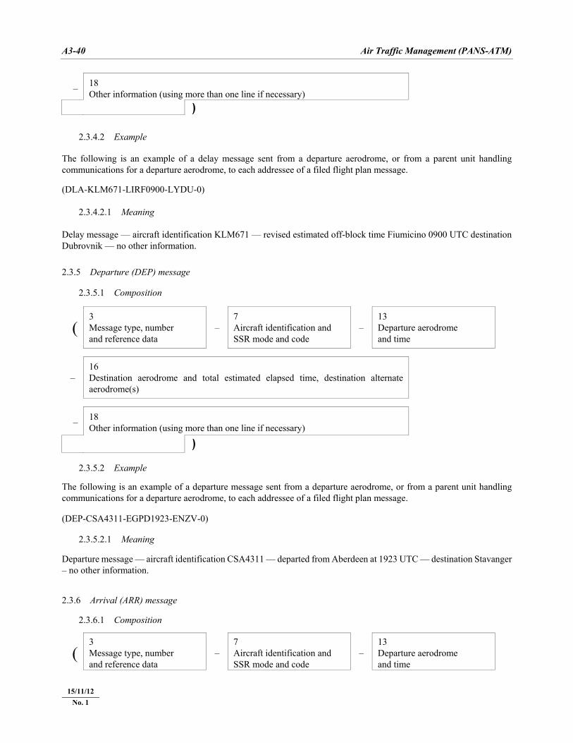
A3-40 Air Traffic Management (PANS-ATM)
22/11/07
– 18 Other information (using more than one line if necessary)
) 2.3.4.2 Example The following is an example of a delay message sent from a departure aerodrome, or from a parent unit handling communications for a departure aerodrome, to each addressee of a filed flight plan message. (DLA-KLM671-LIRF0900-LYDU-0) 2.3.4.2.1 Meaning Delay message — aircraft identification KLM671 — revised estimated off-block time Fiumicino 0900 UTC destination Dubrovnik — no other information. 2.3.5 Departure (DEP) message 2.3.5.1 Composition
( 3 Message type, number and reference data
– 7 Aircraft identification and SSR mode and code
– 13 Departure aerodrome and time
– 16 Destination aerodrome and total estimated elapsed time, destination alternate aerodrome(s)
– 18 Other information (using more than one line if necessary)
) 2.3.5.2 Example The following is an example of a departure message sent from a departure aerodrome, or from a parent unit handling communications for a departure aerodrome, to each addressee of a filed flight plan message. (DEP-CSA4311-EGPD1923-ENZV-0) 2.3.5.2.1 Meaning Departure message — aircraft identification CSA4311 — departed from Aberdeen at 1923 UTC — destination Stavanger – no other information. 2.3.6 Arrival (ARR) message 2.3.6.1 Composition
( 3 Message type, number and reference data
– 7 Aircraft identification and SSR mode and code
– 13 Departure aerodrome and time
15/11/12 No. 1
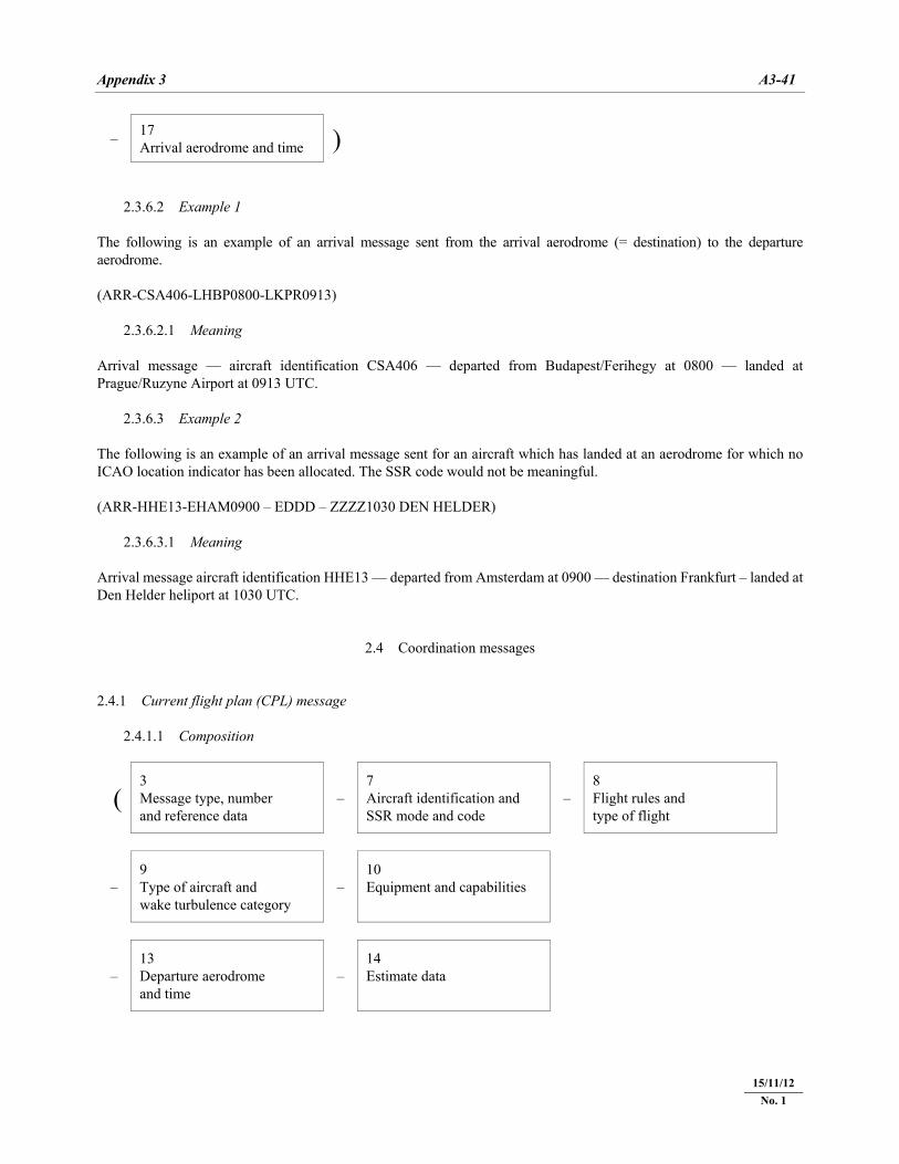
Appendix 3 A3-41
22/11/07
– 17 Arrival aerodrome and time )
2.3.6.2 Example 1 The following is an example of an arrival message sent from the arrival aerodrome (= destination) to the departure aerodrome. (ARR-CSA406-LHBP0800-LKPR0913) 2.3.6.2.1 Meaning Arrival message — aircraft identification CSA406 — departed from Budapest/Ferihegy at 0800 — landed at Prague/Ruzyne Airport at 0913 UTC. 2.3.6.3 Example 2 The following is an example of an arrival message sent for an aircraft which has landed at an aerodrome for which no ICAO location indicator has been allocated. The SSR code would not be meaningful. (ARR-HHE13-EHAM0900 – EDDD – ZZZZ1030 DEN HELDER) 2.3.6.3.1 Meaning Arrival message aircraft identification HHE13 — departed from Amsterdam at 0900 — destination Frankfurt – landed at Den Helder heliport at 1030 UTC.
2.4 Coordination messages 2.4.1 Current flight plan (CPL) message 2.4.1.1 Composition
( 3 Message type, number and reference data
– 7 Aircraft identification and SSR mode and code
– 8 Flight rules and type of flight
– 9 Type of aircraft and wake turbulence category
– 10 Equipment and capabilities
– 13 Departure aerodrome and time
– 14 Estimate data
15/11/12 No. 1
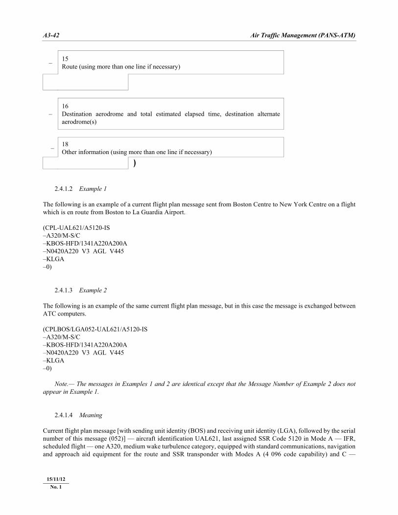
A3-42 Air Traffic Management (PANS-ATM)
22/11/07
– 15 Route (using more than one line if necessary)
– 16 Destination aerodrome and total estimated elapsed time, destination alternate aerodrome(s)
– 18 Other information (using more than one line if necessary)
) 2.4.1.2 Example 1 The following is an example of a current flight plan message sent from Boston Centre to New York Centre on a flight which is en route from Boston to La Guardia Airport. (CPL-UAL621/A5120-IS –A320/M-S/C –KBOS-HFD/1341A220A200A –N0420A220 V3 AGL V445 –KLGA –0) 2.4.1.3 Example 2 The following is an example of the same current flight plan message, but in this case the message is exchanged between ATC computers. (CPLBOS/LGA052-UAL621/A5120-IS –A320/M-S/C –KBOS-HFD/1341A220A200A –N0420A220 V3 AGL V445 –KLGA –0) Note.— The messages in Examples 1 and 2 are identical except that the Message Number of Example 2 does not appear in Example 1. 2.4.1.4 Meaning Current flight plan message [with sending unit identity (BOS) and receiving unit identity (LGA), followed by the serial number of this message (052)] — aircraft identification UAL621, last assigned SSR Code 5120 in Mode A — IFR, scheduled flight — one A320, medium wake turbulence category, equipped with standard communications, navigation and approach aid equipment for the route and SSR transponder with Modes A (4 096 code capability) and C —
15/11/12 No. 1
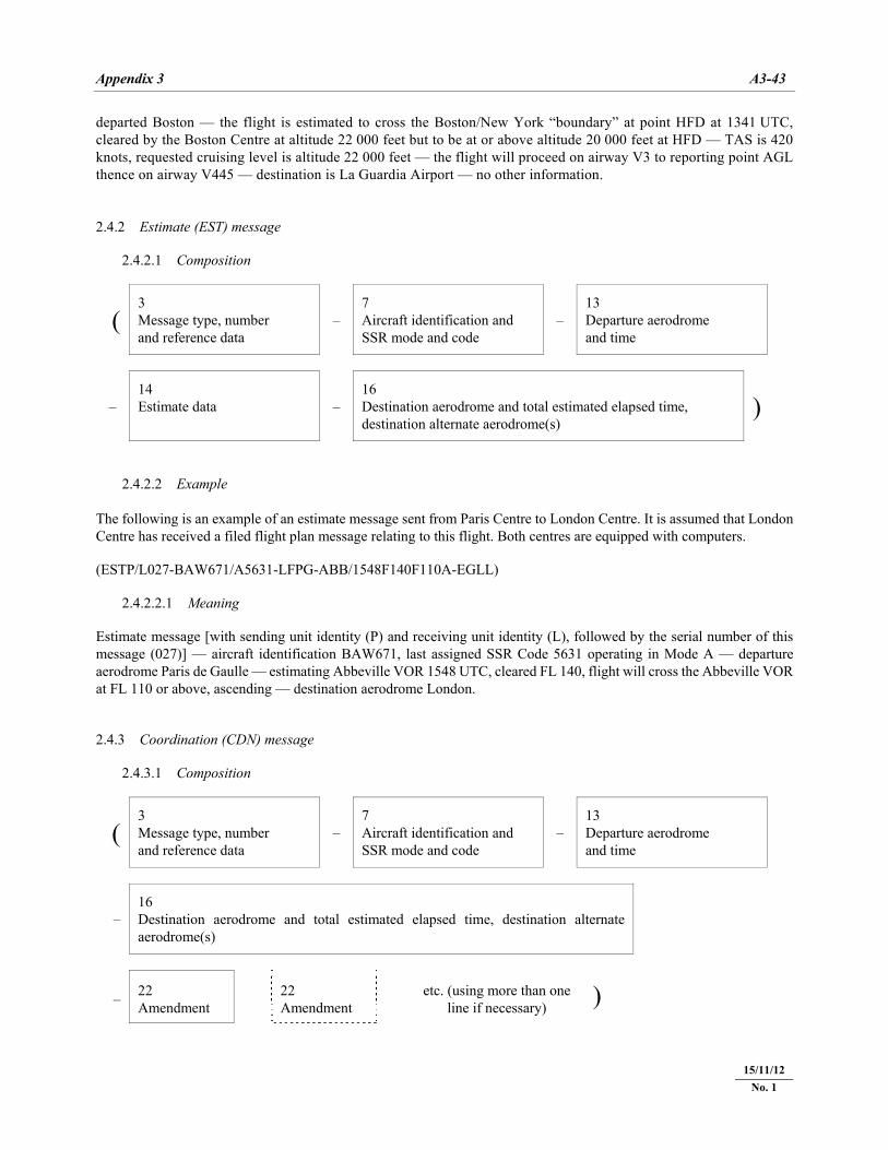
Appendix 3 A3-43
22/11/07
departed Boston — the flight is estimated to cross the Boston/New York “boundary” at point HFD at 1341 UTC, cleared by the Boston Centre at altitude 22 000 feet but to be at or above altitude 20 000 feet at HFD — TAS is 420 knots, requested cruising level is altitude 22 000 feet — the flight will proceed on airway V3 to reporting point AGL thence on airway V445 — destination is La Guardia Airport — no other information. 2.4.2 Estimate (EST) message 2.4.2.1 Composition
( 3 Message type, number and reference data
– 7 Aircraft identification and SSR mode and code
– 13 Departure aerodrome and time
– 14 Estimate data –
16 Destination aerodrome and total estimated elapsed time, destination alternate aerodrome(s)
) 2.4.2.2 Example The following is an example of an estimate message sent from Paris Centre to London Centre. It is assumed that London Centre has received a filed flight plan message relating to this flight. Both centres are equipped with computers. (ESTP/L027-BAW671/A5631-LFPG-ABB/1548F140F110A-EGLL) 2.4.2.2.1 Meaning Estimate message [with sending unit identity (P) and receiving unit identity (L), followed by the serial number of this message (027)] — aircraft identification BAW671, last assigned SSR Code 5631 operating in Mode A — departure aerodrome Paris de Gaulle — estimating Abbeville VOR 1548 UTC, cleared FL 140, flight will cross the Abbeville VOR at FL 110 or above, ascending — destination aerodrome London. 2.4.3 Coordination (CDN) message 2.4.3.1 Composition
( 3 Message type, number and reference data
– 7 Aircraft identification and SSR mode and code
– 13 Departure aerodrome and time
– 16 Destination aerodrome and total estimated elapsed time, destination alternate aerodrome(s)
– 22 Amendment
22 Amendment etc. (using more than one
line if necessary) )
15/11/12 No. 1
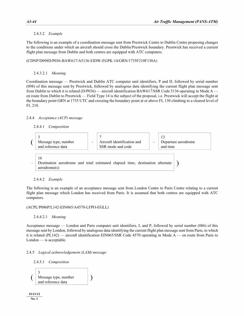
A3-44 Air Traffic Management (PANS-ATM)
22/11/07
2.4.3.2 Example The following is an example of a coordination message sent from Prestwick Centre to Dublin Centre proposing changes to the conditions under which an aircraft should cross the Dublin/Prestwick boundary. Prestwick has received a current flight plan message from Dublin and both centres are equipped with ATC computers. (CDNP/D098D/P036-BAW617/A5136-EIDW-EGPK-14/GRN/1735F210F130A) 2.4.3.2.1 Meaning Coordination message — Prestwick and Dublin ATC computer unit identifiers, P and D, followed by serial number (098) of this message sent by Prestwick, followed by analogous data identifying the current flight plan message sent from Dublin to which it is related (D/P036) — aircraft identification BAW617/SSR Code 5136 operating in Mode A — en route from Dublin to Prestwick — Field Type 14 is the subject of the proposal, i.e. Prestwick will accept the flight at the boundary point GRN at 1735 UTC and crossing the boundary point at or above FL 130 climbing to a cleared level of FL 210. 2.4.4 Acceptance (ACP) message 2.4.4.1 Composition
( 3 Message type, number and reference data
– 7 Aircraft identification and SSR mode and code
– 13 Departure aerodrome and time
– 16 Destination aerodrome and total estimated elapsed time, destination alternate aerodrome(s)
) 2.4.4.2 Example The following is an example of an acceptance message sent from London Centre to Paris Centre relating to a current flight plan message which London has received from Paris. It is assumed that both centres are equipped with ATC computers. (ACPL/P086P/L142-EIN065/A4570-LFPO-EGLL) 2.4.4.2.1 Meaning Acceptance message — London and Paris computer unit identifiers, L and P, followed by serial number (086) of this message sent by London, followed by analogous data identifying the current flight plan message sent from Paris, to which it is related (PL142) — aircraft identification EIN065/SSR Code 4570 operating in Mode A — en route from Paris to London — is acceptable. 2.4.5 Logical acknowledgement (LAM) message 2.4.5.1 Composition
( 3 Message type, number and reference data
)
15/11/12 No. 1
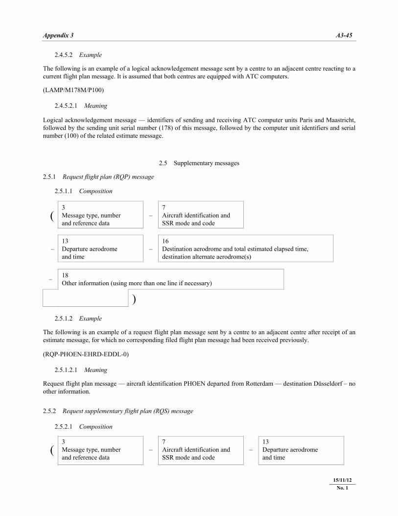
Appendix 3 A3-45
22/11/07
2.4.5.2 Example The following is an example of a logical acknowledgement message sent by a centre to an adjacent centre reacting to a current flight plan message. It is assumed that both centres are equipped with ATC computers. (LAMP/M178M/P100) 2.4.5.2.1 Meaning Logical acknowledgement message — identifiers of sending and receiving ATC computer units Paris and Maastricht, followed by the sending unit serial number (178) of this message, followed by the computer unit identifiers and serial number (100) of the related estimate message.
2.5 Supplementary messages 2.5.1 Request flight plan (RQP) message 2.5.1.1 Composition
( 3 Message type, number and reference data
– 7 Aircraft identification and SSR mode and code
– 13 Departure aerodrome and time
– 16 Destination aerodrome and total estimated elapsed time, destination alternate aerodrome(s)
– 18 Other information (using more than one line if necessary)
) 2.5.1.2 Example The following is an example of a request flight plan message sent by a centre to an adjacent centre after receipt of an estimate message, for which no corresponding filed flight plan message had been received previously. (RQP-PHOEN-EHRD-EDDL-0) 2.5.1.2.1 Meaning Request flight plan message — aircraft identification PHOEN departed from Rotterdam — destination Düsseldorf – no other information. 2.5.2 Request supplementary flight plan (RQS) message 2.5.2.1 Composition
( 3 Message type, number and reference data
– 7 Aircraft identification and SSR mode and code
– 13 Departure aerodrome and time
15/11/12 No. 1
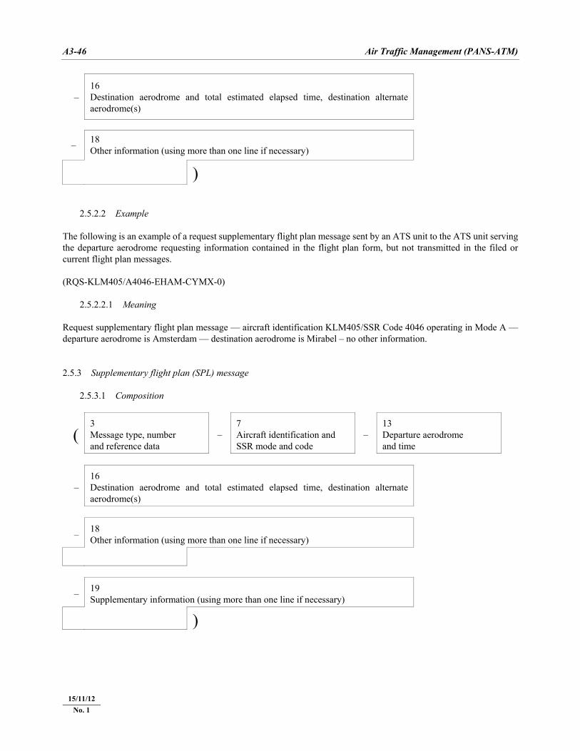
A3-46 Air Traffic Management (PANS-ATM)
22/11/07
– 16 Destination aerodrome and total estimated elapsed time, destination alternate aerodrome(s)
– 18 Other information (using more than one line if necessary)
) 2.5.2.2 Example The following is an example of a request supplementary flight plan message sent by an ATS unit to the ATS unit serving the departure aerodrome requesting information contained in the flight plan form, but not transmitted in the filed or current flight plan messages. (RQS-KLM405/A4046-EHAM-CYMX-0) 2.5.2.2.1 Meaning Request supplementary flight plan message — aircraft identification KLM405/SSR Code 4046 operating in Mode A — departure aerodrome is Amsterdam — destination aerodrome is Mirabel – no other information. 2.5.3 Supplementary flight plan (SPL) message 2.5.3.1 Composition
( 3 Message type, number and reference data
– 7 Aircraft identification and SSR mode and code
– 13 Departure aerodrome and time
– 16 Destination aerodrome and total estimated elapsed time, destination alternate aerodrome(s)
– 18 Other information (using more than one line if necessary)
– 19 Supplementary information (using more than one line if necessary)
)
15/11/12 No. 1
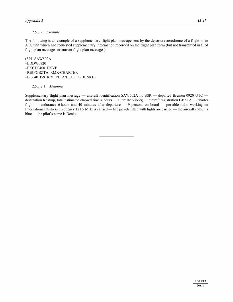
Appendix 3 A3-47
22/11/07
2.5.3.2 Example The following is an example of a supplementary flight plan message sent by the departure aerodrome of a flight to an ATS unit which had requested supplementary information recorded on the flight plan form (but not transmitted in filed flight plan messages or current flight plan messages). (SPL-SAW502A –EDDW0920 –EKCH0400 EKVB –REG/GBZTA RMK/CHARTER –E/0640 P/9 R/V J/L A/BLUE C/DENKE) 2.5.3.2.1 Meaning Supplementary flight plan message — aircraft identification SAW502A no SSR — departed Bremen 0920 UTC — destination Kastrup, total estimated elapsed time 4 hours — alternate Viborg — aircraft registration GBZTA — charter flight — endurance 6 hours and 40 minutes after departure — 9 persons on board — portable radio working on International Distress Frequency 121.5 MHz is carried — life jackets fitted with lights are carried — the aircraft colour is blue — the pilot’s name is Denke.
___________________
15/11/12 No. 1

�������