Embed Size (px)
Citation preview
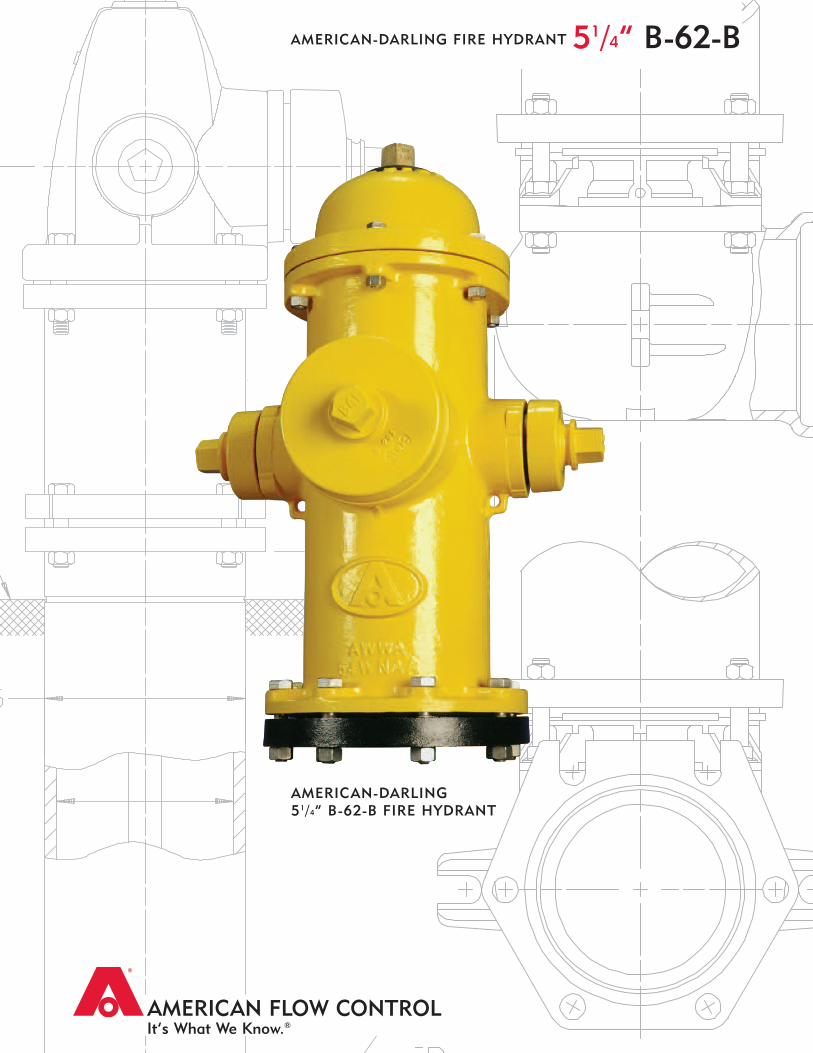
AMERICAN FLOW CONTROLIt’s What We Know.®
AMERICAN-DARLING51/4” B-62-B FIRE HYDRANT
51/4” B-62-BAMERICAN-DARLING FIRE HYDRANT
1
Fully complies with AWWA C-502 and is available UL 246 listed and Factory Mutual Approved for allowable configurations.
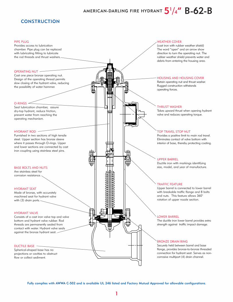
CONSTRUCTION
51/4” B-62-BAMERICAN-DARLING FIRE HYDRANT
OPERATING NUTCast one piece bronze operating nut.Design of the operating thread permitsslow closing of the hydrant valve, reducingthe possibility of water hammer.
O-RINGSSeal lubrication chamber, assuredry-top hydrant, reduce friction,prevent water from reaching theoperating mechanism.
HYDRANT RODFurnished in two sections of high tensilesteel. Upper section has bronze sleevewhere it passes through O-rings. Upperand lower sections are connected by castiron coupling using stainless steel pins.
HYDRANT VALVEConsists of a cast iron valve top and valvebottom and hydrant valve rubber. Rodthreads are permanently sealed fromcontact with water. Hydrant valve sealsagainst the bronze hydrant seat.
BASE BOLTS AND NUTSAre stainless steel forcorrosion resistance.
BRONZE DRAIN RINGSecurely held between barrel and baseflange, provides bronze-to-bronze threadedconnection for hydrant seat. Serves as non-corrosive multiport (4) drain channel.
PIPE PLUGProvides access to lubricationchamber. Pipe plug can be replacedwith lubricating fitting to lubricatethe rod threads and thrust washers.
WEATHER COVER(cast iron with rubber weather shield)The word “open” and an arrow showdirection to turn the operating nut. Therubber weather shield prevents water anddebris from entering the housing area.
HOUSING AND HOUSING COVERRetain operating nut and thrust washer.Rugged construction withstandsoperating forces.
THRUST WASHERTakes upward thrust when opening hydrantvalve and reduces operating torque.
LOWER BARRELThe ductile iron lower barrel provides extrastrength against traffic impact damage.
UPPER BARRELDuctile iron with markings identifyingsize, model, and year of manufacture.
HYDRANT SEATMade of bronze, with accuratelymachined seat for hydrant valvewith (3) drain ports.
DUCTILE BASESpherical-shaped base has noprojections or cavities to obstructflow or collect sediment.
TRAFFIC FEATUREUpper barrel is connected to lower barrelwith breakable traffic flange and 8 boltsand nuts. This feature allows 360°rotation of upper nozzle section.
TOP TRAVEL STOP NUTProvides a positive limit to main rod travel.Eliminates contact of valve bottom withinterior of base, thereby protecting coating.
2
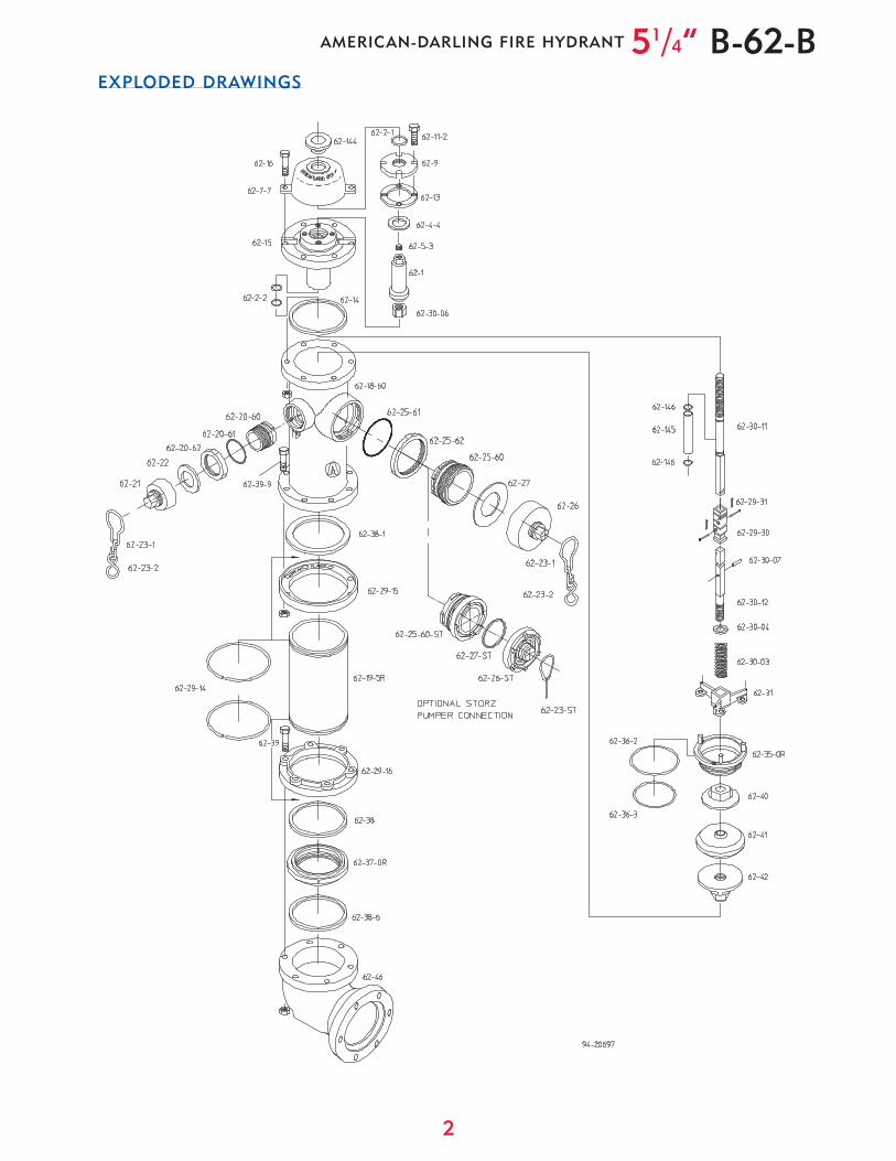
EXPLODED DRAWINGS
51/4” B-62-BAMERICAN-DARLING FIRE HYDRANT
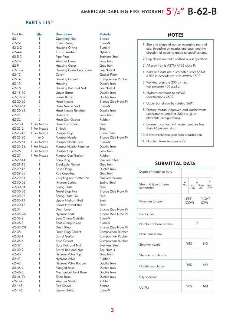
Part No. Qty. Description Material62-1 1 Operating Nut Bronze62-2-1 1 Cover O-ring Buna-N62-2-2 2 Housing O-ring Buna-N62-4-4 1 Thrust Washer Nylatron62-5-3 1 Pipe Plug Stainless Steel62-7-7 1 Weather Cover Gray Iron62-9 1 Housing Cover Gray Iron62-11-2 4 Housing Cover Cap Screw See Note 462-13 1 Cover Gasket Fiber62-14 1 Housing Gasket Composition Rubber62-15 1 Housing Ductile Iron62-16 6 Housing Bolt and Nut See Note 462-18-60 1 Upper Barrel Ductile Iron62-19-SR 1 Lower Barrel Ductile Iron62-20-60 2 Hose Nozzle Bronze (See Note 9)62-20-61 2 Hose Nozzle Seal Buna-N62-20-62 2 Hose Nozzle Retainer Ductile Iron62-21 2 Hose Cap Gray Iron62-22 2 Hose Cap Gasket Rubber62-23-1 1 Per Nozzle Hose Cap Chain Steel62-23-2 1 Per Nozzle S-Hook Steel62-23-18 1 Per Nozzle Pumper Cap Chain Steel62-25-60 1 or 0 Pumper Nozzle Bronze (See Note 9)62-25-61 1 Per Nozzle Pumper Nozzle Seal Buna-N62-25-62 1 Per Nozzle Pumper Nozzle Retainer Ductile Iron62-26 1 Per Nozzle Pumper Cap Gray Iron62-27 1 Per Nozzle Pumper Cap Gasket Rubber62-29-14 2 Snap Ring Stainless Steel62-29-15 1 Breakable Flange Gray Iron62-29-16 1 Base Flange Ductile Iron62-29-30 1 Rod Coupling Gray Iron62-29-31 2 Coupling and Cotter Pin Stainless/Bronze62-30-03 1 Hydrant Spring Spring Steel62-30-04 1 Spring Plate Steel62-30-06 1 Travel Stop Nut Bronze (See Note 9)62-30-07 1 Spring Plate Pin Steel62-30-11 1 Upper Hydrant Rod Steel62-30-12 1 Lower Hydrant Rod Steel62-31 1 Drain Lever Bronze (See Note 9)62-35-OR 1 Hydrant Seat Bronze (See Note 9)62-36-2 1 Seat O-ring-Outside Buna-N62-36-3 1 Seat O-ring-Inside Buna-N62-37-OR 1 Drain Ring Bronze (See Note 9)62-38 1 Drain Ring Gasket Composition Rubber62-38-1 1 Barrel Gasket Composition Rubber62-38-6 1 Base Gasket Composition Rubber62-39 8 Base Bolt and Nut Stainless Steel62-39-9 8 Barrel Bolt and Nut See Note 462-40 1 Hydrant Valve Top Gray Iron62-41 1 Hydrant Valve Rubber62-42 1 Hydrant Valve Bottom Ductile Iron62-46-2 1 Flanged Base Ductile Iron62-46-5 1 Mechanical Joint Base Ductile Iron62-46-TY 1 Tyton Base Ductile Iron62-144 1 Weather Shield Rubber62-145 1 Rod Sleeve Bronze62-146 2 Sleeve O-ring Buna-N
3
PARTS LIST
51/4” B-62-BAMERICAN-DARLING FIRE HYDRANT
Depth of trench or bury
Size and type of baseconnection
Direction to open
Paint color
Number of hose nozzles
Hose nozzle size
Steamer nozzle
Steamer nozzle size
Nozzle cap chains
City specified
UL-FM
YES NO
4"M.J.
6"M.J. TytonFLG AC
YES NO
1. Size and shape of nut on operating nut and cap, threading on nozzles and caps, and thedirection of opening made to specifications.
2. Cap chains are not furnished unless specified.
3. All gray iron is ASTM A126 class B.
4. Bolts and nuts are rustproofed steel ASTMA307 in accordance with AWWA C502.
5. Working pressure 200 p.s.i.g.,test pressure 400 p.s.i.g.
6. Hydrant conforms to AWWAspecifications C502.
7. Upper barrel can be rotated 360°.
8. Factory Mutual Approved and Underwriters Laboratories Listed at 200 p.s.i.g. in allowable configurations.
9. Bronze in contact with water contains less than 16 percent zinc.
10. 6-inch mechanical joint base is ductile iron.
11. Nominal turns to open is 22.
LEFT RIGHT(CCW) (CW)
2
SUBMITTAL DATA
NOTES
8"M.J.FLG
YES NO

4
Fire hydrants shall meet or exceedAWWA C502, latest revision. Ratedworking pressure shall be 200 p.s.i.g.,test pressure shall be 400 p.s.i.g. andhydrants shall include the followingspecific design criteria:
The main valve closure shall be ofthe compression type, opening againstthe pressure and closing with thepressure. Traffic feature to be designedfor easy 360° rotation of nozzle sectionduring field installation.
There shall be a sealed lubrication
chamber with triple O-rings to sealoperating threads from the waterwayand accomodate an anti-frictionthrust washer.
The main valve opening shall not beless than 5-1/4” and be designed sothat removal of all working parts canbe accomplished without excavating.
The bronze seat shall be threadedinto mating threads of bronze for easyfield repair.
The draining system of the hydrantshall be bronze and be positively
activated by the main operating rod.Hydrant drains shall close completely
after no more than three turns ofthe operating nut. There shall be aminimum of three internal ports andfour drain port outlets to the exterior ofthe hydrant. Drain shutoff to be bydirect compression closure. Friction lossnot to exceed 3.5 p.s.i.g. at 1000 gpmthrough 4-1/2” pumper nozzle.
Hydrants shall be American FlowControl's American-Darling B-62-B.
Spring-Loaded Multiport DrainsThree drain ports and four drain
outlets are standard features on the B-62-B hydrant. The rod springassures drains close after only threeturns of the rod. This important safetyfeature prevents wash-outs that canhappen on hydrant designs that do nothave this important feature.
• Travel stop located in top of hydrant
• Bronze-to-bronze seating
• Positive compression, spring-loaded multiport drains
• Lower valve ball is epoxy coated
• Short, lightweight, disassembly wrench
• Easy 360° rotation of nozzle section
• Centrifugally cast high-strengthductile iron barrels
• Ductile iron 6” base with epoxy-coating
• Sealed lubrication chamber
• Double O-ring protected bronze valve seat
The B-62-B hydrant has these standard features:
American Flow Control’s American-Darling B-62-B hydrant incorporatesover 80 years in design, manufacture,and field experience. This meansdependable and efficient operationwhen needed.
Introduced in 1962, the B-62-Bhydrant is rated at 200 p.s.i.g. and seattested at 400 p.s.i.g. This hydrant meetsand exceeds all requirements of AWWA
C502 for dry-barrel hydrants. The B-62-Bhydrant is loaded with the features youexpect from a high-quality fire hydrant.The all bronze seat and bronze drain ringassure that the B-62-B hydrant is easilyrepaired by just one person.
Optional UL-FMThe B-62-B hydrant is listed by
Underwriters Laboratories, Inc. asmeeting their standard UL 246, latest
edition. The Factory Mutual ResearchCorporation has approved the B-62-B.
Both Underwriters Laboratories andFactory Mutual Research Corporationrequire that we consistentlymanufacture and test our hydrants infull accordance with their stringentrequirements. Our facilities are subjectto periodic inspections to assure weare in compliance to their standards.
BENEFITS
SPECIFICATIONS
FEATURES
Sealed Lubrication ChamberSeals operating threads from grit and
moisture and reduces maintenance.
Top Travel Stop NutHelps prevent stem buckling and
damage to bronze components whichmay occur if excessive torque is appliedin the full open position.
51/4” B-62-BAMERICAN-DARLING FIRE HYDRANT
AFC-4/06-6M
Distributed By:
American-Darling ValveP.O. Box 2727
Birmingham, AL 35202-2727Phone: 1-800-326-7861
Fax: 1-800-610-3569
e-mail: [email protected]
Waterous Company125 Hardman Avenue South
South St. Paul, MN 55075-2421Phone: 1-888-266-3686
Fax: 1-800-601-2809
e-mail: [email protected]
American Flow Control American-Darling Valve and Waterous
A Division of American Cast Iron Pipe Company
www.acipco.com/afc