Embed Size (px)
Citation preview
COMPUTER ARCHITECTURE CPU ORGANISATION
SECOND FLOOR, SULTAN TOWER, ROORKEE – 247667 UTTARAKHAND PH: (01332) 266328 Web: www.amiestudycircle.com 1/30
AMIE(I) STUDY CIRCLE(REGD.) A Focused Approach
CPU Organisation
INSTRUCTIONS AND INSTRUCTION SEQUENCING
Each instruction of the CPU contain specific information fields, which are required to execute it. These information fields of instructions are called elements of instruction. These are :
Operation code : The operation code field in the, instruction specifies the operation to be performed. The operation is specified by binary code, hence the name operation code or simply opcode for 8085 processor operation code for Add B instruction is 80H.
Source/Destination operand : The source/destination operand field directly specifies the source/destination operand for the instruction. In 8085, the instruction MOV A,B has B register as a source operand and A register as a destination operand, because this instruction copies the contents of register B to register A.
Source operand address : We know that the operation specified by the instruction may require one or more operands. The source operand may be in the CPU register or in the memory. Many times the instruction specifies the address of the source operand so that operand(s) can be accessed and operated by the CPU according to the instruction. In 8085, the source operand address for instruction Add M is given by HL
register pair.
Destination operand address : The operation executed by the CPU may produce result. Most of the times the result is stored in one of the operand. Such operand is known as destination operand. The instruction which produce result specifies the destination operand address. In 8085, the destination operand address for instruction INR M is given by HL register pair. Because INR M instruction increments the contents of memory location specified by HL register pair and stores the result in the same memory location.
Next instruction address : The next instruction address tells the CPU from where to fetch the next instruction after completion of execution of current instruction. For JUMP and BRANCH instructions the address of the next instruction is specified within the instruction. However, for other instructions, the next instruction to be fetched immediately follows the current instruction. For example, in 8085, the
instruction JMP 2000H specifies the next instruction address as 2000H.
Each instruction in a program specifies operation to be performed and data to be processed. For this reason, an instruction is divided into two parts : its operation code (opcode) and its
operands. The operand is an another name for data. It may appear in different forms :
Addresses
Numbers
COMPUTER ARCHITECTURE CPU ORGANISATION
SECOND FLOOR, SULTAN TOWER, ROORKEE – 247667 UTTARAKHAND PH: (01332) 266328 Web: www.amiestudycircle.com 2/30
AMIE(I) STUDY CIRCLE(REGD.) A Focused Approach
Characters
Logical Data
Addresses : The addresses are in fact a form of data. In many situations, some calculation
must be performed on the operand reference in an instruction to determine physical address.
Numbers : All computer supports numeric data types. The common numeric data ' types are :
Integer or Fixed Point
Floating-point
Decimal
Characters : For documentation a common form of data is text or character strings. Today, most of the computers use ASCII (American Standard Code for Information Interchange) code for character represented by a unique 7-bit pattern ; thus, 123 different characters can be represented. However, the ASCII encoded characters are always stored and transmitted using
8-bits per character. The eighth bit may be set to 0 or used as a parity bit for error detection.
Another code used to encode characters is the Extended Binary Coded Decimal Interchange
Code ( EBCDIC).
Logical Data : Most of the processors interpret data as a bit, byte, word, or double word. These are referred to as units of data. When data is viewed as n, 1-bit items of data, each item having the value 0 or 1, it is considered as a logical data. The logical data is used to store an array of Boolean or binary data items and with logical data we can manipulate the bits of data items.
A computer has a set of instructions that allows the user to formulate any data-processing task. To carry out tasks, regardless of whether a computer has 100 instructions or 300 instructions, its instructions must be capable of performing following basic operations :
Data transfers between the memory and the processor registers.
Arithmetic and logic operations on data.
Program sequencing and control.
I/O control.
Data Transfer Instructions : Data transfer instructions include the instructions for data transfer between the memory and the processor register. The instructions may include the byte transfer or word transfer instructions.
Arithmetic or Logical Instructions : These instructions are also known as data processing instructions. The arithmetic instructions provide computational capabilities for processing numeric data, whereas logic instructions provide capabilities of performing logical
operations on the bits of a word.
Program Sequencing and Control Instructions : This instruction type mainly includes test and branch instructions. Test instructions are used to test the value of a data word or the
COMPUTER ARCHITECTURE CPU ORGANISATION
SECOND FLOOR, SULTAN TOWER, ROORKEE – 247667 UTTARAKHAND PH: (01332) 266328 Web: www.amiestudycircle.com 3/30
AMIE(I) STUDY CIRCLE(REGD.) A Focused Approach
status of a computation. Branch instructions are used to branch to a different set of
instructions depending on the decision made.
I/O Control : The I/O control instructions include the instructions for data transfer between processor and input/output devices. The instructions may include the byte transfer or word
transfer instructions.
Before going to discuss these instructions we understand first some notations used to represent these instructions.
Register Transfer Notation
We have seen that in a computer system data transfer takes place between processor registers and memory and between processor registers and I/O system. These data transfers can be
represented by standard notations given below :
Processor registers are represented by notations RO, Rl, R2, ... and so on.
The addresses of the memory locations are represented by names such as LOC, PLACE, MEM, etc
I/O registers are represented by names such as DATAIN, DATAOUT and so on.
The contents of register or memory location are denoted by placing square brackets around the name of the register or memory location.
Let us see following examples for clear understanding.
Example
R2 [LOC]
This expression states that the contents of memory location LOC are transferred into the
processor register R2.
Example
R3 [Rl] + [R2]
This expression states that the contents of processor registers Rl and R2 are added and the
result is stored into the processor register R3.
Example
[LOC] [Rl] - [R2]
This expression states that the contents of the processor register R2 is subtracted from processor register Rl and the result is stored into the memory location LOC.
The notations explained above are commonly known as register transfer notations (RTN). In these notations, the data represented by the right-hand side of the expression is transferred to the location specified by the left hand side of the expression, overwriting the old contents of that location.
COMPUTER ARCHITECTURE CPU ORGANISATION
SECOND FLOOR, SULTAN TOWER, ROORKEE – 247667 UTTARAKHAND PH: (01332) 266328 Web: www.amiestudycircle.com 4/30
AMIE(I) STUDY CIRCLE(REGD.) A Focused Approach
Assembly Language Notation
Assembly language notations are the another type of notations used to represent machine instructions and programs. These notations use assembly language formats. However, register names, names of memory locations are same as that of register notations. Let us see some examples.
Example
MOVE R2, Rl
This expression states that the contents of processor register R2 are transferred to processor register Rl. Thus the contents register R2 remain unchanged but contents of register Rl are overwritten.
Example
ADD Rl, R2, R3
This expression states that the contents of processor registers Rl and R2 are added and the result is stored in the register R3.
It is important to note that the above expressions written in the assembly language notations has three fields : operation, source and destination having their positions from left to right. This order is followed by many computer. But there are many computers in which the order of source and destination operands is reversed.
Basic Instruction Types
The processor instructions can be classified according to their operations and according to the number of address references required by them. In this section we are going to discuss basic
instruction types according to the number of address references required by the instructions.
Accordingly to address reference there are three address, two address, one address and zero
address reference instructions. Let us see examples of each of them.
Three Address Instructions
The three address instruction can be represented symbolically as
ADD A, B, C
where A, B, C are the variables. These variable names are assigned to distinct locations in the memory. In this instruction operands A and B are called source operands and operand C is called destination operand and ADD is the operation to be performed on the operands. Thus
the general instruction format for three address instruction is
Operation Source 1, Source 2, Destination
The number of bits required to represent such instruction include :
COMPUTER ARCHITECTURE CPU ORGANISATION
SECOND FLOOR, SULTAN TOWER, ROORKEE – 247667 UTTARAKHAND PH: (01332) 266328 Web: www.amiestudycircle.com 5/30
AMIE(I) STUDY CIRCLE(REGD.) A Focused Approach
Bits required to specify the three memory addresses of the three operands. If n-bits are required to specify one memory address, 3n bits are required to specify three memory
addresses.
Bits required to specify the operation.
Two Address Instructions
The two address instruction can be represented symbolically as ADD A, B
This instruction adds the contents of variables A and B and stores the sum in variable B destroying its previous contents. Here, operand A is source operand; however operand B serves as both source and destination operand. The general instruction format for two address
instruction is
Operation Source, Destination
To represent this instruction less number of bits are required as compared to three address
instruction. The number of bits required to represent two address instruction include :
Bits required to specify the two memory addresses of the two operands, i.e. 2n bits.
Bits required to specify the operation.
One Address Instruction
The one address instruction can be represented symbolically as
ADD B
This instruction adds the contents of variable A into the processor register called accumulator and stores the sum back into the accumulator destroying the previous contents of the accumulator. In this instruction the second operand is assumed implicitly in a unique location
accumulator. The general instruction format for one address instruction is
Operation Source
Few more examples of one address instructions are :
LOAD A This instruction copies the contents of memory location A into the
accumulator.
STORE B This instruction copies the contents of accumulator into memory
location B.
In one address instruction, it is important to note that the operand specified in the instruction can be either source operand or destination operand depending on the instruction. For example, in LOAD A instruction, the operand specified in the instruction is a source operand whereas the operand specified in the STORE B instruction is a destination operand. Similarly, in one address instruction the implied operand (accumulator) can be either source or destination depending on the instruction.
COMPUTER ARCHITECTURE CPU ORGANISATION
SECOND FLOOR, SULTAN TOWER, ROORKEE – 247667 UTTARAKHAND PH: (01332) 266328 Web: www.amiestudycircle.com 6/30
AMIE(I) STUDY CIRCLE(REGD.) A Focused Approach
Zero Address Instructions
In these instructions, the locations of all operands are defined implicitly. Such instructions are
found in machines that store operands in - a structure called a pushdown stack.
From above discussion we can easily understand that the instruction with only one address will require less number of bits to represent it, and instruction with three addresses will require more number of bits to represent it. Therefore, to access entire instruction from the memory, the instruction with three addresses requires more memory accesses while instruction with one address requires less memory accesses.
The speed of instruction execution is mainly depend on how much memory accesses it requires for the execution. If memory accesses are more, more Line is required to execute the instruction. Therefore, the execution time for three address instructions is more than the
execution time for one address instructions.
To have a less execution time we have to use instructions with minimum memory accesses. For this instead of referring the operands from memory it is advised to refer operands from processor registers. When machine level language programs are generated by compilers from high-level languages, the intelligent compilers see that the maximum references to the operands He in the processor registers.
Instruction Execution and Straight-Line Sequencing
Uptil now we have seen that instruction consists of opcode or opcode and oprand/s or opcode and operand address. Every processor has some basic types of instructions such as data transfer instructions, arithmetic instructions, logical instructions, branch instructions and so on. To perform a particular task on the computer, it is programmers job to select and write appropriate instructions one after the other, i.e. programmer has to write instructions in a proper sequence. This job of programmer is known as instruction sequencing. The instructions written in a proper sequence to execute a particular task is called program.
Processor executes a program with the help of program counter (PC). PC holds the address of the instruction to be executed next. To begin execution of a program, the address of its first instruction is placed into the PC. Then, the processor control circuits use the information (address of memory) in the PC to fetch and execute instructions, one at a time, in the order of increasing addresses. This is called straight-line sequencing. During the execution of instruction, the PC is incremented by the length of the current instruction in execution. For example, if currently executing instruction length is 3 bytes, the PC is incremented by 3 so
that it points to the instruction to be executed next.
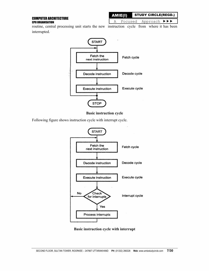
Let us see how instruction is executed. The complete instruction cycle involves three operations Instruction fetching, opcode decoding and instruction execution.
Following shows the basic instruction cycle. After each instruction cycle, central processing unit checks for any valid interrupt request. If so, central processing unit fetches the instructions from the interrupt service routine and after completion of interrupt service
COMPUTER ARCHITECTURE CPU ORGANISATION
SECOND FLOOR, SULTAN TOWER, ROORKEE – 247667 UTTARAKHAND PH: (01332) 266328 Web: www.amiestudycircle.com 7/30
AMIE(I) STUDY CIRCLE(REGD.) A Focused Approach
routine, central processing unit starts the new instruction cycle from where it has been
interrupted.
Basic instruction cycle
Following figure shows instruction cycle with interrupt cycle.
Basic instruction cycle with interrupt
COMPUTER ARCHITECTURE CPU ORGANISATION
SECOND FLOOR, SULTAN TOWER, ROORKEE – 247667 UTTARAKHAND PH: (01332) 266328 Web: www.amiestudycircle.com 8/30
AMIE(I) STUDY CIRCLE(REGD.) A Focused Approach
Instruction Fetch Cycle :
In this cycle, the instruction is fetched from the memory location whose address is in the PC.
This instruction is placed in the instruction register (IR) in the processor.
Instruction Decode Cycle :
In this cycle, the opcode of the instruction stored in the instruction register is
decoded/examined to determine which operation is to be performed.
Instruction Execution Cycle :
In this cycle, the specified operation is performed by the processor. This often involves fetching operands from the memory or from processor registers, performing an arithmetic or logical operation, and storing the result in the destination location. During the instruction execution, PC contents are incremented to point to the next instruction. After completion of execution of the current instruction, the PC contains the address of the next instruction, and a
new instruction fetch cycle can begin.
Conditional Codes
The condition code flags are used to store the results of certain condition when certain operations are performed during execution of the program. The condition code flags are stored in the status registers. The status register is also referred to as flag register. ALU operations and certain register operations may set or reset one or more bits in the status register. Status bits lead to a new set of microprocessor instructions. These instructions permit the execution of a program to change flow on the basis of the condition of bits in the status register. So the condition bits in the status register can be used to take logical decisions
within the program. Some of the common condition code flags are:
Carry/Borrow
The carry bit is set when the summation of two 8-bit numbers is greater than 1111 1111
(FFH). A borrow is generated when a large number is subtracted from a smaller number.
Zero
The zero bit is set when the contents of register are zero after any operation. This happens not only when you decrement the register, but also when any arithmetic or logical operation
causes the contents of register to be zero.
Negative or Sign
In 2's complement arithmetic, the most significant bit is a sign bit. If this bit is logic 1, the number is negative number, otherwise a positive number. The negative bit or sign bit is set when any arithmetic or logical operation gives a negative result.
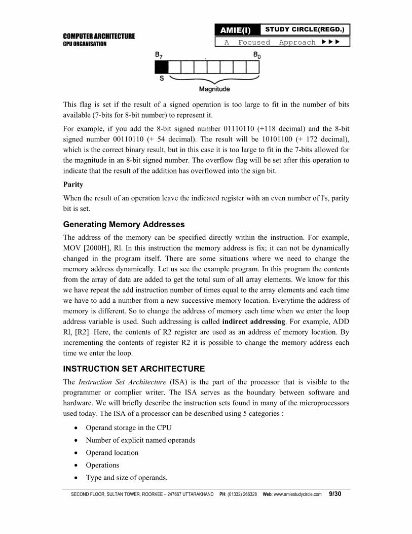
Overflow Flag
In 2's complement arithmetic, most significant bit is used to represent sign and remaining bits are used to represent magnitude of a number (see following figure).
COMPUTER ARCHITECTURE CPU ORGANISATION
SECOND FLOOR, SULTAN TOWER, ROORKEE – 247667 UTTARAKHAND PH: (01332) 266328 Web: www.amiestudycircle.com 9/30
AMIE(I) STUDY CIRCLE(REGD.) A Focused Approach
This flag is set if the result of a signed operation is too large to fit in the number of bits available (7-bits for 8-bit number) to represent it.
For example, if you add the 8-bit signed number 01110110 (+118 decimal) and the 8-bit signed number 00110110 (+ 54 decimal). The result will be 10101100 (+ 172 decimal), which is the correct binary result, but in this case it is too large to fit in the 7-bits allowed for the magnitude in an 8-bit signed number. The overflow flag will be set after this operation to
indicate that the result of the addition has overflowed into the sign bit.
Parity
When the result of an operation leave the indicated register with an even number of l's, parity
bit is set.
Generating Memory Addresses
The address of the memory can be specified directly within the instruction. For example, MOV [2000H], Rl. In this instruction the memory address is fix; it can not be dynamically changed in the program itself. There are some situations where we need to change the memory address dynamically. Let us see the example program. In this program the contents from the array of data are added to get the total sum of all array elements. We know for this we have repeat the add instruction number of times equal to the array elements and each time we have to add a number from a new successive memory location. Everytime the address of memory is different. So to change the address of memory each time when we enter the loop address variable is used. Such addressing is called indirect addressing. For example, ADD Rl, [R2]. Here, the contents of R2 register are used as an address of memory location. By incrementing the contents of register R2 it is possible to change the memory address each time we enter the loop.
INSTRUCTION SET ARCHITECTURE
The Instruction Set Architecture (ISA) is the part of the processor that is visible to the programmer or complier writer. The ISA serves as the boundary between software and hardware. We will briefly describe the instruction sets found in many of the microprocessors
used today. The ISA of a processor can be described using 5 categories :
Operand storage in the CPU
Number of explicit named operands
Operand location
Operations
Type and size of operands.
COMPUTER ARCHITECTURE CPU ORGANISATION
SECOND FLOOR, SULTAN TOWER, ROORKEE – 247667 UTTARAKHAND PH: (01332) 266328 Web: www.amiestudycircle.com 10/30
AMIE(I) STUDY CIRCLE(REGD.) A Focused Approach
Of all the above, the most distinguishing factor is the operand storage. The three most
common types of ISAs are:
Stack
The operands are implicitly on top of the stack. An stack is a group of registers organized as a last-in-first-out (LIFO) structure. In such a structure, the operands stored first, through the push operation, can only be accessed last, through a pop operation: the order of access to the operands is reverse of the storage operation. An analogy of the stack is a "plate-dispenser" found in several self-service cafeterias. Arithmetic and logic operations successively pick operands from the top-of-the-stack (TOS). and push the results on the TOS at the end of the operation. In stack based machines, operand addresses need not be specified during the arithmetic or logical operations. Therefore, these machines are also called 0-address machines.
Accumulator
One operand is implicitly the accumulator.
General Purpose Register (GPR)
All operands are explicitly mentioned, they are either registers or memory locations.
In general purpose register machines, a number of registers are available within the CPU. These registers do not have dedicated functions, and can be employed for a variety of purposes. To identify the register within an instruction, a small number of bits are required in an instruction word. For example, to identify' one of the 64 registers of the CPU. a 6-bit field is required in the instruction.
CPU registers are faster than cache memory. Registers are also easily and more effectively used by the compiler compared to other forms of internal storage. Registers can also be used to hold variables, thereby reducing memory traffic. This increases the execution speed and reduces code size (fewer bits required to code register names compared to memory) .In addition to data, registers can also hold addresses and pointers (i.e.. the address of an address). This increases the flexibility available to the programmer.
A number of dedicated, or special purpose registers are also available in general-purpose machines, but many of them are not available to the programmer. Examples of transparent registers include the stack pointer, the program counter, memory address register, memory
data register and condition codes (or flags) register, etc.
We should understand that in reality, most machines are a combination of these machine types. Accumulator machines have the advantage of being more efficient as these can store
intermediate results of an operation within the CPU.
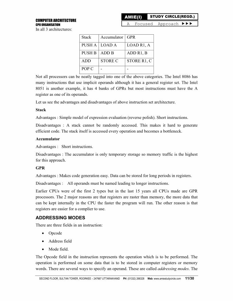
Let us look at the assembly code of A = B + C;
COMPUTER ARCHITECTURE CPU ORGANISATION
SECOND FLOOR, SULTAN TOWER, ROORKEE – 247667 UTTARAKHAND PH: (01332) 266328 Web: www.amiestudycircle.com 11/30
AMIE(I) STUDY CIRCLE(REGD.) A Focused Approach
In all 3 architectures:
Stack Accumulator GPR
PUSH A LOAD A LOAD R1, A
PUSH B ADD B ADD R1, B
ADD STORE C STORE R1, C
POP C - -
Not all processors can be neatly tagged into one of the above categories. The Intel 8086 has many instructions that use implicit operands although it has a general register set. The Intel 8051 is another example, it has 4 banks of GPRs but most instructions must have the A
register as one of its operands.
Let us see the advantages and disadvantages of above instruction set architecture.
Stack
Advantages : Simple model of expression evaluation (reverse polish). Short instructions.
Disadvantages : A stack cannot be randomly accessed. This makes it hard to generate efficient code. The stack itself is accessed every operation and becomes a bottleneck.
Accumulator
Advantages : Short instructions.
Disadvantages : The accumulator is only temporary storage so memory traffic is the highest for this approach.
GPR
Advantages : Makes code generation easy. Data can be stored for long periods in registers.
Disadvantages : All operands must be named leading to longer instructions.
Earlier CPUs were of the first 2 types but in the last 15 years all CPUs made are GPR processors. The 2 major reasons are that registers are raster than memory, the more data that can be kept internally in the CPU the faster the program will run. The other reason is that registers are easier for a complier to use.
ADDRESSING MODES
There are three fields in an instruction:
Opcode
Address field
Mode field.
The Opcode field in the instruction represents the operation which is to be performed. The operation is performed on some data that is to be stored in computer registers or memory words. There are several ways to specify an operand. These are called addressing modes. The
COMPUTER ARCHITECTURE CPU ORGANISATION
SECOND FLOOR, SULTAN TOWER, ROORKEE – 247667 UTTARAKHAND PH: (01332) 266328 Web: www.amiestudycircle.com 12/30
AMIE(I) STUDY CIRCLE(REGD.) A Focused Approach
way the operands are chosen during the execution of a program is depend on the addressing mode of the instruction. Addressing modes define a rule or a way by which the value of the operand is referenced or we reach where the value of operand is present. The operand can be present in processor register, memory, I/O port and in the instruction itself. Addressing modes define a technique to reach where the operand that is required in our instruction is
present.
Computers use addressing techniques for the purpose of accommodating one or both of the
following provisions:
To give programming versatility to the user by providing facilities such as pointer to memory. Counters for loop control, indexing of data and program relocation.
To reduce the number of bits in the addressing field of the instruction.
There is one register PC (Program Counter) that keeps track of the instructions in the program stored in memory. PC holds the address of the next instruction that is to be executed. Whenever an instruction is fetched from memory. PC is incremented by 1. The second phase of the machine cycle determines the operation that we have to performed the addressing mode of the instruction and the location where the operand is present. Then we execute the instruction and returned to step 1 to fetch the next instruction from memory. The availability of the addressing modes gives the experienced assembly language programmer flexibility for writing program that are more efficient with respect to the number of instructions and
execution time.
Now discussing the addressing modes following standard terms are used:
Address (A)
Contents of an address field in the instruction that refers to a memory location.
Register (R)
Contents of an address field that refers to a register in the instruction.
Program Counter (PC)
The Program Counter (PC) keeps tracks of the instructions in the program stored in memory. It holds the address of the instruction that is to be executed and incremented every time when an instruction is fetched from memory.
Effective Address (EA)
The effective address is the address of the operand when the operand is actually stored. It is defined to be the memory address obtained from the computation dictated by the given
addressing mode.
Direct Addressing
A very simple form of addressing is direct addressing, in which the address field contains the
effective address of the operand:
EA = A
COMPUTER ARCHITECTURE CPU ORGANISATION
SECOND FLOOR, SULTAN TOWER, ROORKEE – 247667 UTTARAKHAND PH: (01332) 266328 Web: www.amiestudycircle.com 13/30
AMIE(I) STUDY CIRCLE(REGD.) A Focused Approach
The technique was common in earlier generations of computers but is not common on
contemporary architectures.
It requires only one memory reference and no special calculation. The obvious limitation is that it provides only a limited address space.
Indirect Addressing
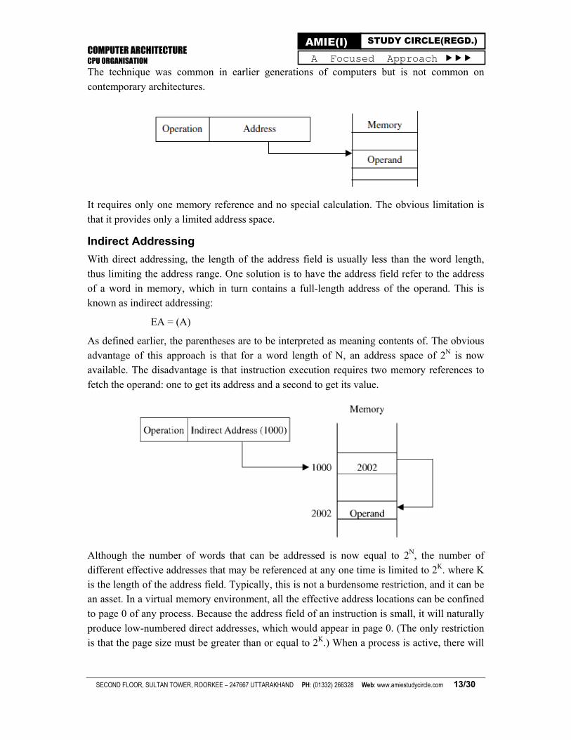
With direct addressing, the length of the address field is usually less than the word length, thus limiting the address range. One solution is to have the address field refer to the address of a word in memory, which in turn contains a full-length address of the operand. This is known as indirect addressing:
EA = (A)
As defined earlier, the parentheses are to be interpreted as meaning contents of. The obvious advantage of this approach is that for a word length of N, an address space of 2N is now available. The disadvantage is that instruction execution requires two memory references to
fetch the operand: one to get its address and a second to get its value.
Although the number of words that can be addressed is now equal to 2N, the number of different effective addresses that may be referenced at any one time is limited to 2K. where K is the length of the address field. Typically, this is not a burdensome restriction, and it can be an asset. In a virtual memory environment, all the effective address locations can be confined to page 0 of any process. Because the address field of an instruction is small, it will naturally produce low-numbered direct addresses, which would appear in page 0. (The only restriction is that the page size must be greater than or equal to 2K.) When a process is active, there will
COMPUTER ARCHITECTURE CPU ORGANISATION
SECOND FLOOR, SULTAN TOWER, ROORKEE – 247667 UTTARAKHAND PH: (01332) 266328 Web: www.amiestudycircle.com 14/30
AMIE(I) STUDY CIRCLE(REGD.) A Focused Approach
be repeated references to page 0, causing it to remain in real memory. Thus, an indirect
memory reference will involve, at most, one page fault rather than two.
A rarely used variant of indirect addressing is multilevel or cascaded indirect addressing:
EA = (...(A)...)
In this case, one bit of a full-word address is an indirect flag (I). If the I bit is 0, then the word contains the EA. If the I bit is 1, then another level of indirection is invoked. There does not appear to be any particular advantage to this approach- and its disadvantage is that three or more memory references could be required to fetch an operand.
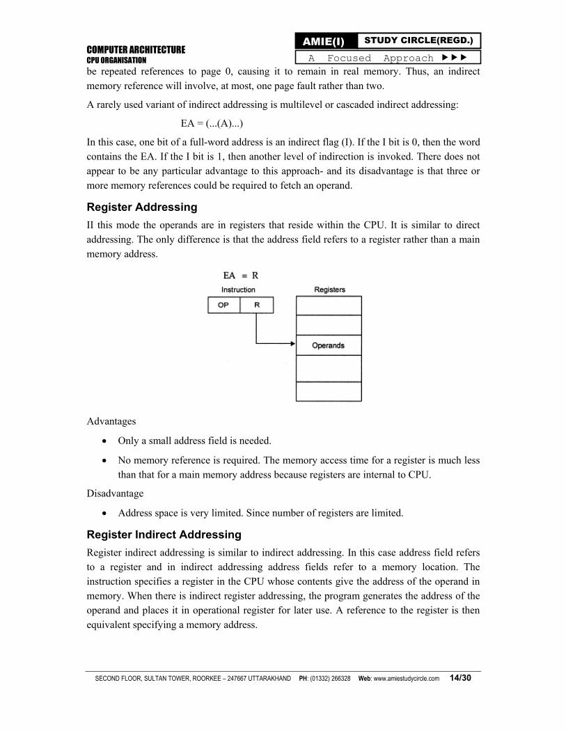
Register Addressing
II this mode the operands are in registers that reside within the CPU. It is similar to direct addressing. The only difference is that the address field refers to a register rather than a main
memory address.
Advantages
Only a small address field is needed.
No memory reference is required. The memory access time for a register is much less than that for a main memory address because registers are internal to CPU.
Disadvantage
Address space is very limited. Since number of registers are limited.
Register Indirect Addressing
Register indirect addressing is similar to indirect addressing. In this case address field refers to a register and in indirect addressing address fields refer to a memory location. The instruction specifies a register in the CPU whose contents give the address of the operand in memory. When there is indirect register addressing, the program generates the address of the operand and places it in operational register for later use. A reference to the register is then
equivalent specifying a memory address.
COMPUTER ARCHITECTURE CPU ORGANISATION
SECOND FLOOR, SULTAN TOWER, ROORKEE – 247667 UTTARAKHAND PH: (01332) 266328 Web: www.amiestudycircle.com 15/30
AMIE(I) STUDY CIRCLE(REGD.) A Focused Approach
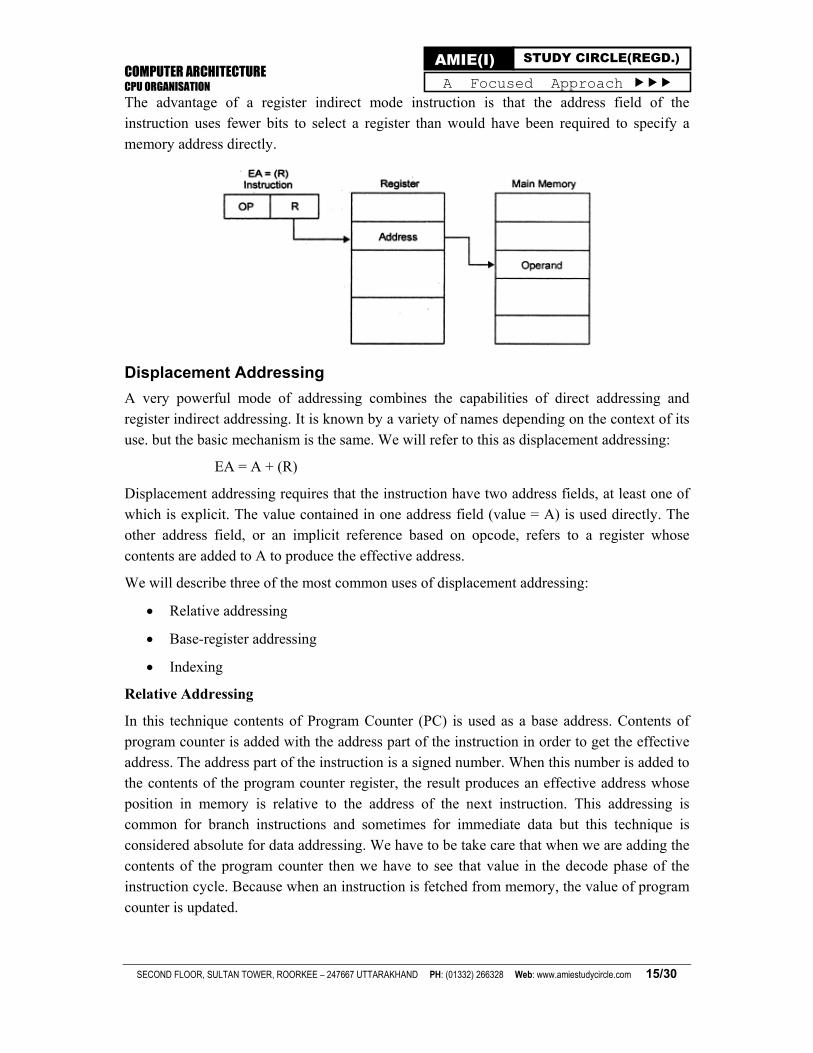
The advantage of a register indirect mode instruction is that the address field of the instruction uses fewer bits to select a register than would have been required to specify a
memory address directly.
Displacement Addressing
A very powerful mode of addressing combines the capabilities of direct addressing and register indirect addressing. It is known by a variety of names depending on the context of its
use. but the basic mechanism is the same. We will refer to this as displacement addressing:
EA = A + (R)
Displacement addressing requires that the instruction have two address fields, at least one of which is explicit. The value contained in one address field (value = A) is used directly. The other address field, or an implicit reference based on opcode, refers to a register whose
contents are added to A to produce the effective address.
We will describe three of the most common uses of displacement addressing:
Relative addressing
Base-register addressing
Indexing
Relative Addressing
In this technique contents of Program Counter (PC) is used as a base address. Contents of program counter is added with the address part of the instruction in order to get the effective address. The address part of the instruction is a signed number. When this number is added to the contents of the program counter register, the result produces an effective address whose position in memory is relative to the address of the next instruction. This addressing is common for branch instructions and sometimes for immediate data but this technique is considered absolute for data addressing. We have to be take care that when we are adding the contents of the program counter then we have to see that value in the decode phase of the instruction cycle. Because when an instruction is fetched from memory, the value of program
counter is updated.
COMPUTER ARCHITECTURE CPU ORGANISATION
SECOND FLOOR, SULTAN TOWER, ROORKEE – 247667 UTTARAKHAND PH: (01332) 266328 Web: www.amiestudycircle.com 16/30
AMIE(I) STUDY CIRCLE(REGD.) A Focused Approach
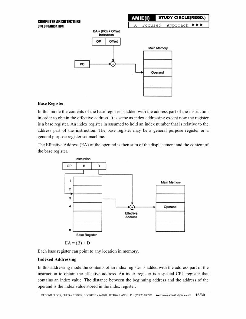
Base Register
In this mode the contents of the base register is added with the address part of the instruction in order to obtain the effective address. It is same as index addressing except now the register is a base register. An index register in assumed to hold an index number that is relative to the address part of the instruction. The base register may be a general purpose register or a
general purpose register set machine.
The Effective Address (EA) of the operand is then sum of the displacement and the content of
the base register.
EA = (B) + D
Each base register can point to any location in memory.
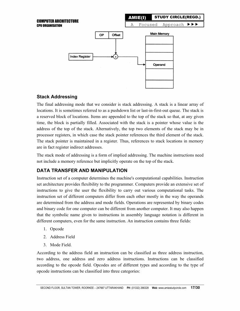
Indexed Addressing
In this addressing mode the contents of an index register is added with the address part of the instruction to obtain the effective address. An index register is a special CPU register that contains an index value. The distance between the beginning address and the address of the operand is the index value stored in the index register.
COMPUTER ARCHITECTURE CPU ORGANISATION
SECOND FLOOR, SULTAN TOWER, ROORKEE – 247667 UTTARAKHAND PH: (01332) 266328 Web: www.amiestudycircle.com 17/30
AMIE(I) STUDY CIRCLE(REGD.) A Focused Approach
Stack Addressing
The final addressing mode that we consider is stack addressing. A stack is a linear array of locations. It is sometimes referred to as a pushdown list or last-in-first-out queue. The stack is a reserved block of locations. Items are appended to the top of the stack so that, at any given time, the block is partially filled. Associated with the stack is a pointer whose value is the address of the top of the stack. Alternatively, the top two elements of the stack may be in processor registers, in which case the stack pointer references the third element of the stack. The stack pointer is maintained in a register. Thus, references to stack locations in memory are in fact register indirect addresses.
The stack mode of addressing is a form of implied addressing. The machine instructions need
not include a memory reference but implicitly operate on the top of the stack.
DATA TRANSFER AND MANIPULATION
Instruction set of a computer determines the machine's computational capabilities. Instruction set architecture provides flexibility to the programmer. Computers provide an extensive set of instructions to give the user the flexibility to carry out various computational tasks. The instruction set of different computers differ from each other mostly in the way the operands are determined from the address and mode fields. Operations are represented by binary codes and binary code for one computer can be different from another computer. It may also happen that the symbolic name given to instructions in assembly language notation is different in
different computers, even for the same instruction. An instruction contains three fields:
1. Opcode
2. Address Field
3. Mode Field.
According to the address field an instruction can be classified as three address instruction, two address, one address and zero address instructions. Instructions can be classified according to the opcode field. Opcodes are of different types and according to the type of
opcode instructions can be classified into three categories:
COMPUTER ARCHITECTURE CPU ORGANISATION
SECOND FLOOR, SULTAN TOWER, ROORKEE – 247667 UTTARAKHAND PH: (01332) 266328 Web: www.amiestudycircle.com 18/30
AMIE(I) STUDY CIRCLE(REGD.) A Focused Approach
1. Data Transfer Instructions
2. Data Manipulation Instructions
3. Program Control Instructions.
Data transfer instructions transfer data from one location to another without changing the contents. Data manipulation instructions are those that perform arithmetic, logic and shift operations. Program control instructions provide decision making capabilities and are responsible for changing the execution sequence. The instruction set of a particular computer determines the register transfer operations and control decisions that are available to the user.
Data Transfer Instructions
Data transfer instructions move the data from one location to another location in computer without changing the contents. The most common data transfer takes place between memory and processor registers, between processor registers and input or output devices and between the processor registers themselves. Each instruction is represented by mnemonic symbol.
Typically there are eight data transfer instructions. These are represented in following table.
Name Mnemonic Symbol
Load LD
Store ST
Move MOV
Exchange XCH
Input IN
Output OUT
Push PUSH
Pop POP
The load instruction has been used mostly to designate a transfer from memory to a processor
register usually an accumulator.
The store instruction designates a transfer from processor register to memory. The move instruction transfer data from one processor register to another, from processor register the memory, from memory to processor register or between two memory words. The exchange instruction swap information between two register or a register and a memory word. The input and output instructions transfer data among processor registers and input or output terminals. The push and pop instructions transfer data between processor registers and a memory stack. The instructions listed in the table is associated with a variety of addressing modes. As an example consider the load to accumulator instruction when used with eight different addressing modes. To be able to write assembly language programs for a computer, it is necessary to know the type of instructions available and also to be familiar with the addressing modes used in the particular computer.
COMPUTER ARCHITECTURE CPU ORGANISATION
SECOND FLOOR, SULTAN TOWER, ROORKEE – 247667 UTTARAKHAND PH: (01332) 266328 Web: www.amiestudycircle.com 19/30
AMIE(I) STUDY CIRCLE(REGD.) A Focused Approach
Data Manipulation Instructions
Data manipulation instructions perform operations on data and provide the computational capabilities for the computer. These instructions change the contents of registers on which the instructions operates. The data manipulation instructions in a typical computer are usually divided into three basic types:
1. Arithmetic Instructions
2. Logical and Bit Manipulation Instructions
3. Shift Instructions.
Each instruction when executed in the computer must go through the fetch phase that reads the binary code of the instruction from memory. The operands are brought in processor registers according to the rules of the instruction addressing mode. The last step is to execute
the instruction in the processor.
Arithmetic Instructions
The four basic arithmetic operations are addition, subtraction, multiplication and division. Some computers provide instructions for all four operations and some computers provides only addition and subtraction directly. Multiplication and division is generated from these
two operations. Typical arithmetic instructions are listed in Table 3.6.
Name Mnemonics
Increment INC
Decrement DEC
Add ADD
Subtract SUB
Multiply MUL
Divide DIV
Add with Carry ADDC
Subtract with Borrow SUBB
Negation NEG
Increment operation adds 1 to the value that is stored in registers or memory word. The decrement instruction subtracts 1 from a value stored in a register or in a memory word. A number with all 0's, produces a number with all l's, when decremented. The addition, subtraction, multiplication and divide instructions may be available for different types of data. An arithmetic instruction may specify fixed print or floating point data, binary or decimal data, single precision or double precision data.
Execution of arithmetic instructions generally set the processor status flags or the condition codes to indicate the outcome of the operation. Examples of such outcomes are the conditions
COMPUTER ARCHITECTURE CPU ORGANISATION
SECOND FLOOR, SULTAN TOWER, ROORKEE – 247667 UTTARAKHAND PH: (01332) 266328 Web: www.amiestudycircle.com 20/30
AMIE(I) STUDY CIRCLE(REGD.) A Focused Approach
generated as a carry or a borrow, an overflow or an underflow, the result is 0 or the result is negative. Thus the condition code register is an implicit operand for most of these instructions. A special carry flip-flop is used to store the carry from an operation. The instruction add with carry performs the addition of two numbers plus the value of the carry from the previous computation. In the same way the "subtract with borrow" instruction subtracts two words and a borrow which may have resulted from a previous subtract operation. The negative operation represents the 2's complement of a number.
Logical Instructions
Logical instructions are used to perform logical operations such as AND, OR, SHIFT, COMPARE, and ROTATE. As the names indicate, these instructions perform, respectively, and. or. shirt, compare, and rotate operations on register or memory contents. Following table presents a number of logical operations.
Logical operation Meaning
AND Perform the logical ANDing of two operands
OR Perform the logical ORing of two operands
EXOR Perform the XORing of two operands
NOT Perform the complement of an operand
COMPARE
Perform logical comparison of two operands and
set Hag accordingly
SHIFT
Perform logical shift (right or left) of the
content
of a register
ROTATE Perform logical shift (right or left) with
wraparound of the content of a register
Control (Sequencing) Instructions
Control (sequencing) instructions are used to change the sequence in which instructions are executed. They take the form of CONDITIONAL BRANCHING {CONDITIONAL JUMP). UNCONDITIONAL BRANCHING (JUMP), or CALL instructions. A common characteristic among these instructions is that their execution changes the program counter (PC) value. The change made in the PC value can be unconditional, for example, in the unconditional branching or the jump instructions. In this case, the earlier value of the PC is lost and execution of the program starts at a new value specified by the instruction. Consider, for example, the instruction JUMP NEW-ADDRESS. Execution of this instruction will cause the PC to be loaded with the memory location represented by NEW-ADDRESS whereby the
instruction stored at this new address is executed. On the other hand.
COMPUTER ARCHITECTURE CPU ORGANISATION
SECOND FLOOR, SULTAN TOWER, ROORKEE – 247667 UTTARAKHAND PH: (01332) 266328 Web: www.amiestudycircle.com 21/30
AMIE(I) STUDY CIRCLE(REGD.) A Focused Approach
the change made in the PC by the branching instruction can be conditional based on the value of a specific flag. Examples of these flags include the Negative (N), Zero (Z). Overflow (V), and Carry (C). These flags represent the individual bits of a specific register, called the CONDITION CODE (CC) REGISTER. The values of flags are set based on the results of executing different instructions. The meaning of each of these flags is shown in Table 2.6.
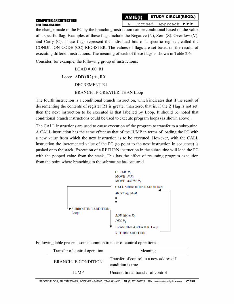
Consider, for example, the following group of instructions.
LOAD #100, R1
Loop: ADD (R2) + , R0
DECREMENT R1
BRANCH-IF-GREATER-THAN Loop
The fourth instruction is a conditional branch instruction, which indicates that if the result of decrementing the contents of register R1 is greater than zero, that is. if the Z Hag is not set. then the next instruction to be executed is that labelled by Loop. It should be noted that conditional branch instructions could be used to execute program loops (as shown above).
The CALL instructions are used to cause execution of the program to transfer to a subroutine. A CALL instruction has the same effect as that of the JUMP in terms of loading the PC with a new value from which the next instruction is to be executed. However, with the CALL instruction the incremented value of the PC (to point to the next instruction in sequence) is pushed onto the stack. Execution of a RETURN instruction in the subroutine will load the PC with the popped value from the stack. This has the effect of resuming program execution from the point where branching to the subroutine has occurred.
Following table presents some common transfer of control operations.
Transfer of control operation Meaning
BRANCH-IF-CONDITION Transfer of control to a new address if condition is true
JUMP Unconditional transfer of control
COMPUTER ARCHITECTURE CPU ORGANISATION
SECOND FLOOR, SULTAN TOWER, ROORKEE – 247667 UTTARAKHAND PH: (01332) 266328 Web: www.amiestudycircle.com 22/30
AMIE(I) STUDY CIRCLE(REGD.) A Focused Approach
CALL Transfer of control to a subroutine
RETURN Transfer of control to the caller routine
Input/Output Instructions
Input and output instructions (I/O instructions) are used to transfer data between the computer and peripheral devices. The two basic I/O instructions used are the INPUT and OUTPUT instructions. The INPUT instruction is used to transfer data from an input device to the processor. Examples of input devices include a keyboard or a mouse. Input devices are interfaced with a computer through dedicated input ports. Computers can use dedicated addresses to address these ports. Suppose that the input port through which a keyboard is connected to a computer carries the unique address 1000. Therefore, execution of the instruction INPUT 1000 will cause the data stored in a specific register in the interface between the keyboard and the computer, call it the input data register, to be moved into a specific register (called the accumulator) in the computer. Similarly, the execution of the instruction OUTPUT 2000 causes the data stored in the accumulator to be moved to the data output register in the output device whose address is 2000. Alternatively, the computer can address these ports in the usual way of addressing memory locations. In this case, the computer can input data from an input device by executing an instruction such as MOVE Rin, R0. This instruction moves the content of the register Rin into the register R0. Similarly, the instruction MOVE R0, Rin moves the contents of register R0 into the register Rin that is, performs an output operation. This latter scheme is called memory-mapped Input/Output. Among the advantages of memory-mapped I/O is the ability to execute a number of memory-dedicated instructions on the registers in the I/O devices in addition to the elimination of the need for dedicated I/O instructions. Its main disadvantage is the need to dedicate part of the
memory address space for I/O devices.
INSTRUCTION FORMATS
An instruction format defines the layout of the bits of an instruction. It must include opcode, zero or more operands and addressing mode for each operand. The instruction length is usually kept in multiple of the character length, or memory transfer length which is usually 8-bits. With this length we will always get an integral number of instructions during a fetch cycle. Once the instruction length is fixed, it is necessary to allocate number of bits for opcode, operand(s) and addressing modes. For an instruction format of a given length, if more number of bits are allocated to opcode field then less number of bits available for addressing. The bits allocation for addressing can be determined by the following factors, which simplifies the task of allocating bits in the instruction.
Number of addressing modes
Number of operands
Number of CPU registers
Number of register sets
COMPUTER ARCHITECTURE CPU ORGANISATION
SECOND FLOOR, SULTAN TOWER, ROORKEE – 247667 UTTARAKHAND PH: (01332) 266328 Web: www.amiestudycircle.com 23/30
AMIE(I) STUDY CIRCLE(REGD.) A Focused Approach
Address range or number of address lines
Address granularity (address can refer byte, word or double word)
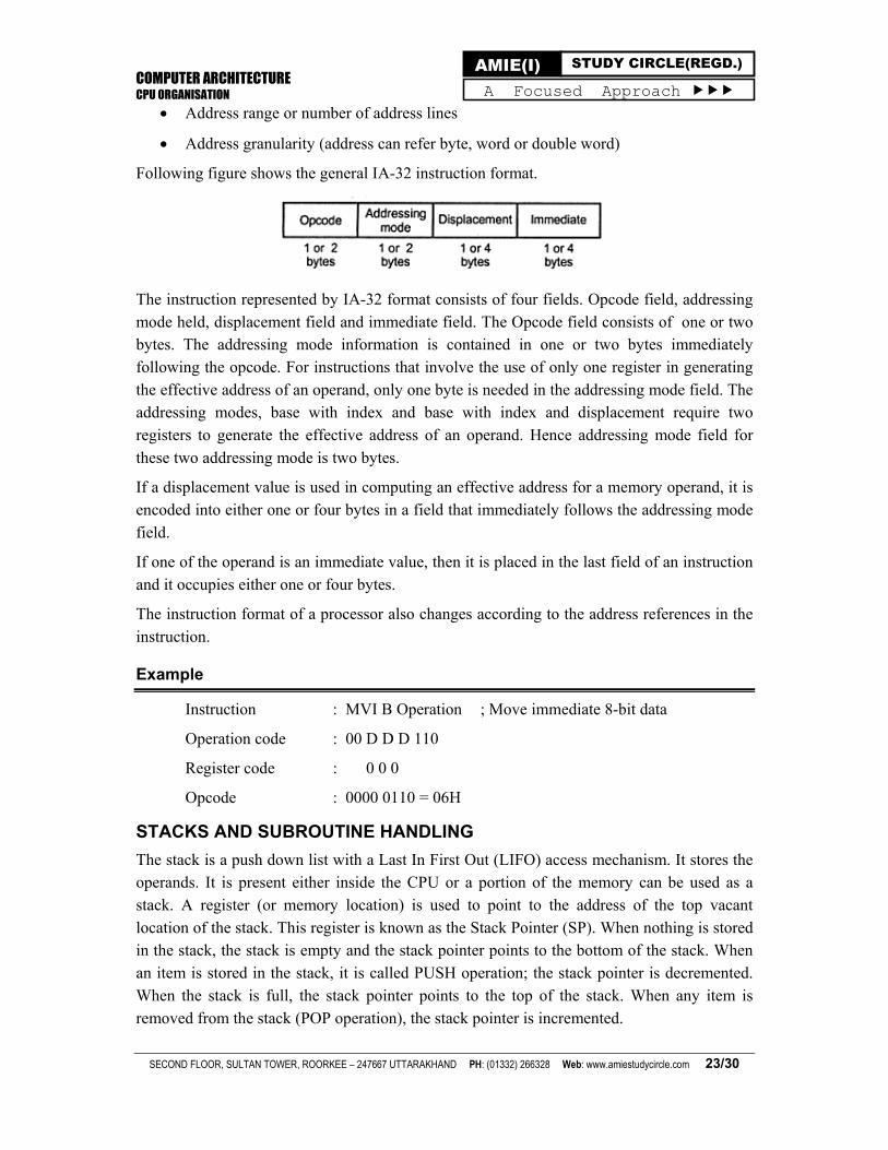
Following figure shows the general IA-32 instruction format.
The instruction represented by IA-32 format consists of four fields. Opcode field, addressing mode held, displacement field and immediate field. The Opcode field consists of one or two bytes. The addressing mode information is contained in one or two bytes immediately following the opcode. For instructions that involve the use of only one register in generating the effective address of an operand, only one byte is needed in the addressing mode field. The addressing modes, base with index and base with index and displacement require two registers to generate the effective address of an operand. Hence addressing mode field for
these two addressing mode is two bytes.
If a displacement value is used in computing an effective address for a memory operand, it is encoded into either one or four bytes in a field that immediately follows the addressing mode
field.
If one of the operand is an immediate value, then it is placed in the last field of an instruction and it occupies either one or four bytes.
The instruction format of a processor also changes according to the address references in the
instruction.
Example
Instruction : MVI B Operation ; Move immediate 8-bit data
Operation code : 00 D D D 110
Register code : 0 0 0
Opcode : 0000 0110 = 06H
STACKS AND SUBROUTINE HANDLING
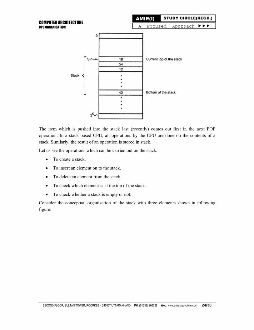
The stack is a push down list with a Last In First Out (LIFO) access mechanism. It stores the operands. It is present either inside the CPU or a portion of the memory can be used as a stack. A register (or memory location) is used to point to the address of the top vacant location of the stack. This register is known as the Stack Pointer (SP). When nothing is stored in the stack, the stack is empty and the stack pointer points to the bottom of the stack. When an item is stored in the stack, it is called PUSH operation; the stack pointer is decremented. When the stack is full, the stack pointer points to the top of the stack. When any item is removed from the stack (POP operation), the stack pointer is incremented.
COMPUTER ARCHITECTURE CPU ORGANISATION
SECOND FLOOR, SULTAN TOWER, ROORKEE – 247667 UTTARAKHAND PH: (01332) 266328 Web: www.amiestudycircle.com 24/30
AMIE(I) STUDY CIRCLE(REGD.) A Focused Approach
The item which is pushed into the stack last (recently) comes out first in the next POP operation. In a stack based CPU, all operations by the CPU are done on the contents of a
stack. Similarly, the result of an operation is stored in stack.
Let us see the operations which can be carried out on the stack.
To create a stack.
To insert an element on to the stack.
To delete an element from the stack.
To check which element is at the top of the stack.
To check whether a stack is empty or not.
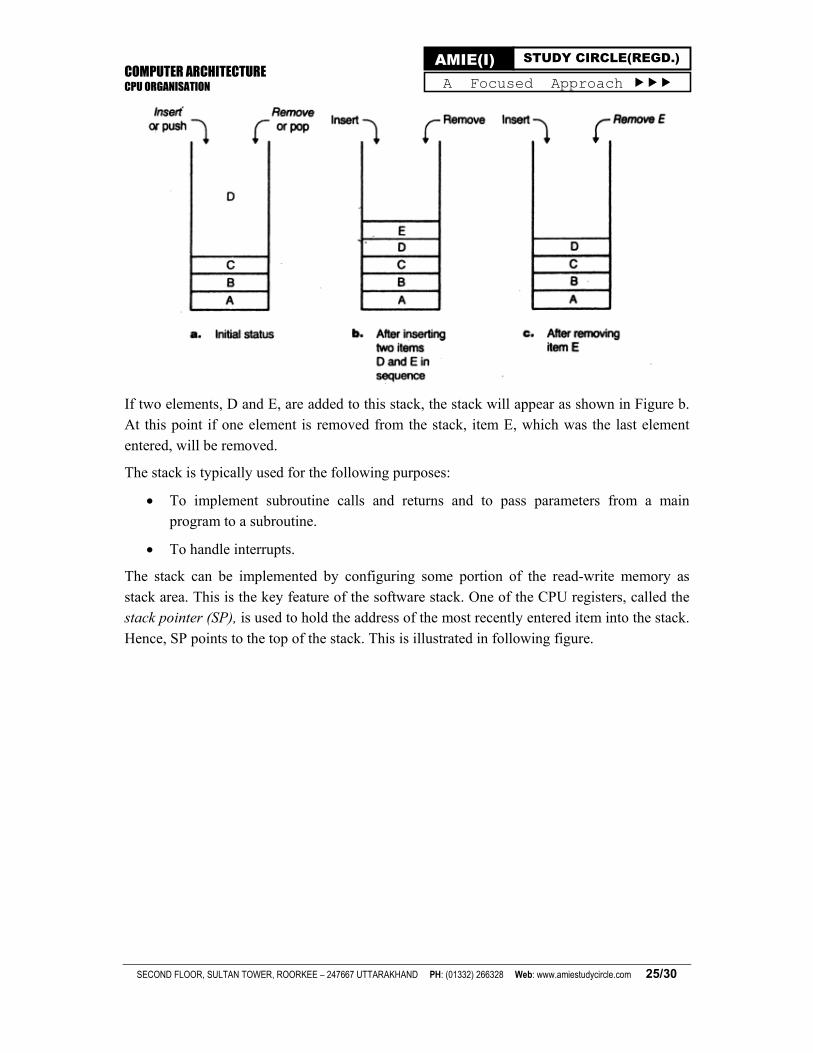
Consider the conceptual organization of the stack with three elements shown in following
figure.
COMPUTER ARCHITECTURE CPU ORGANISATION
SECOND FLOOR, SULTAN TOWER, ROORKEE – 247667 UTTARAKHAND PH: (01332) 266328 Web: www.amiestudycircle.com 25/30
AMIE(I) STUDY CIRCLE(REGD.) A Focused Approach
If two elements, D and E, are added to this stack, the stack will appear as shown in Figure b. At this point if one element is removed from the stack, item E, which was the last element
entered, will be removed.
The stack is typically used for the following purposes:
To implement subroutine calls and returns and to pass parameters from a main program to a subroutine.
To handle interrupts.
The stack can be implemented by configuring some portion of the read-write memory as stack area. This is the key feature of the software stack. One of the CPU registers, called the stack pointer (SP), is used to hold the address of the most recently entered item into the stack.
Hence, SP points to the top of the stack. This is illustrated in following figure.
COMPUTER ARCHITECTURE CPU ORGANISATION
SECOND FLOOR, SULTAN TOWER, ROORKEE – 247667 UTTARAKHAND PH: (01332) 266328 Web: www.amiestudycircle.com 26/30
AMIE(I) STUDY CIRCLE(REGD.) A Focused Approach
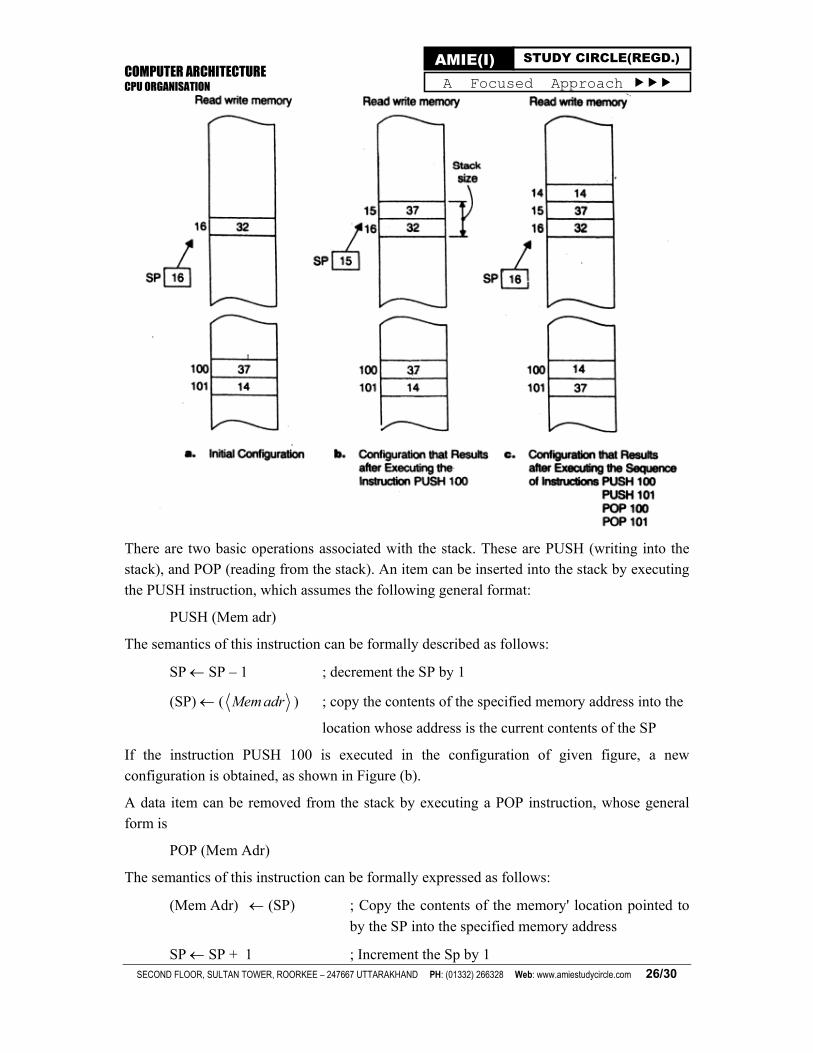
There are two basic operations associated with the stack. These are PUSH (writing into the stack), and POP (reading from the stack). An item can be inserted into the stack by executing
the PUSH instruction, which assumes the following general format:
PUSH (Mem adr)
The semantics of this instruction can be formally described as follows:
SP SP – 1 ; decrement the SP by 1
(SP) ( Mem adr ) ; copy the contents of the specified memory address into the
location whose address is the current contents of the SP
If the instruction PUSH 100 is executed in the configuration of given figure, a new
configuration is obtained, as shown in Figure (b).
A data item can be removed from the stack by executing a POP instruction, whose general form is
POP (Mem Adr)
The semantics of this instruction can be formally expressed as follows:
(Mem Adr) (SP) ; Copy the contents of the memory' location pointed to
by the SP into the specified memory address
SP SP + 1 ; Increment the Sp by 1
COMPUTER ARCHITECTURE CPU ORGANISATION
SECOND FLOOR, SULTAN TOWER, ROORKEE – 247667 UTTARAKHAND PH: (01332) 266328 Web: www.amiestudycircle.com 27/30
AMIE(I) STUDY CIRCLE(REGD.) A Focused Approach
If the sequence of instructions
PUSH 100
PUSH 101
POP 100
POP 101
is executed in the configuration of Figure (a), a new configuration (Figure (c)) is obtained.
In a software stack, the stack size is determined by the initial value stored in the SP. Since a programmer can initialize the SP using the instruction MOV initial value, SP;, stack size is a program-controlled parameter. Theoretically, the size of a stack can be as large as the total
available space in the RWM.
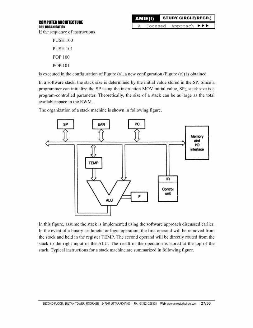
The organization of a stack machine is shown in following figure.
In this figure, assume the stack is implemented using the software approach discussed earlier. In the event of a binary arithmetic or logic operation, the first operand will be removed from the stock and held in the register TEMP. The second operand will be directly routed from the stack to the right input of the ALU. The result of the operation is stored at the top of the
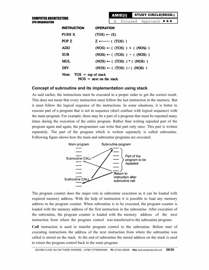
stack. Typical instructions for a stack machine are summarized in following figure.
COMPUTER ARCHITECTURE CPU ORGANISATION
SECOND FLOOR, SULTAN TOWER, ROORKEE – 247667 UTTARAKHAND PH: (01332) 266328 Web: www.amiestudycircle.com 28/30
AMIE(I) STUDY CIRCLE(REGD.) A Focused Approach
Concept of subroutine and its implementation using stack
As said earlier, the instructions must be executed in a proper order to get the correct result. This does not mean that every instruction must follow the last instruction in the memory. But it must follow the logical sequence of the instructions. In some situations, it is better to execute part of a program that is not in sequence (don't confuse with logical sequence) with the main program. For example, there may be a part of a program that must be repeated many times during the execution of the entire program. Rather than writing repealed part of the program again and again, the programmer can write that part only once. This part is written separately. The part of the program which is written separately is called subroutine. Following figure shows how the main and subroutine programs are executed.
The program counter does the major role in subroutine execution as it can be loaded with required memory address. With the help of instruction it is possible to load any memory address in the program counter. When subroutine is to be executed, the program counter is loaded with the memory address of the first instruction in the subroutine. After execution of the subroutine, the program counter is loaded with the memory address of the next instruction from where the program control was transferred to the subroutine program.
Call instruction is used to transfer program control to the subroutine. Before start of executing instructions the address of the next instruction from where the subroutine was called is stored on the stack. At the end of subroutine the stored address on the stack is used to return the program control back to the main program.
COMPUTER ARCHITECTURE CPU ORGANISATION
SECOND FLOOR, SULTAN TOWER, ROORKEE – 247667 UTTARAKHAND PH: (01332) 266328 Web: www.amiestudycircle.com 29/30
AMIE(I) STUDY CIRCLE(REGD.) A Focused Approach
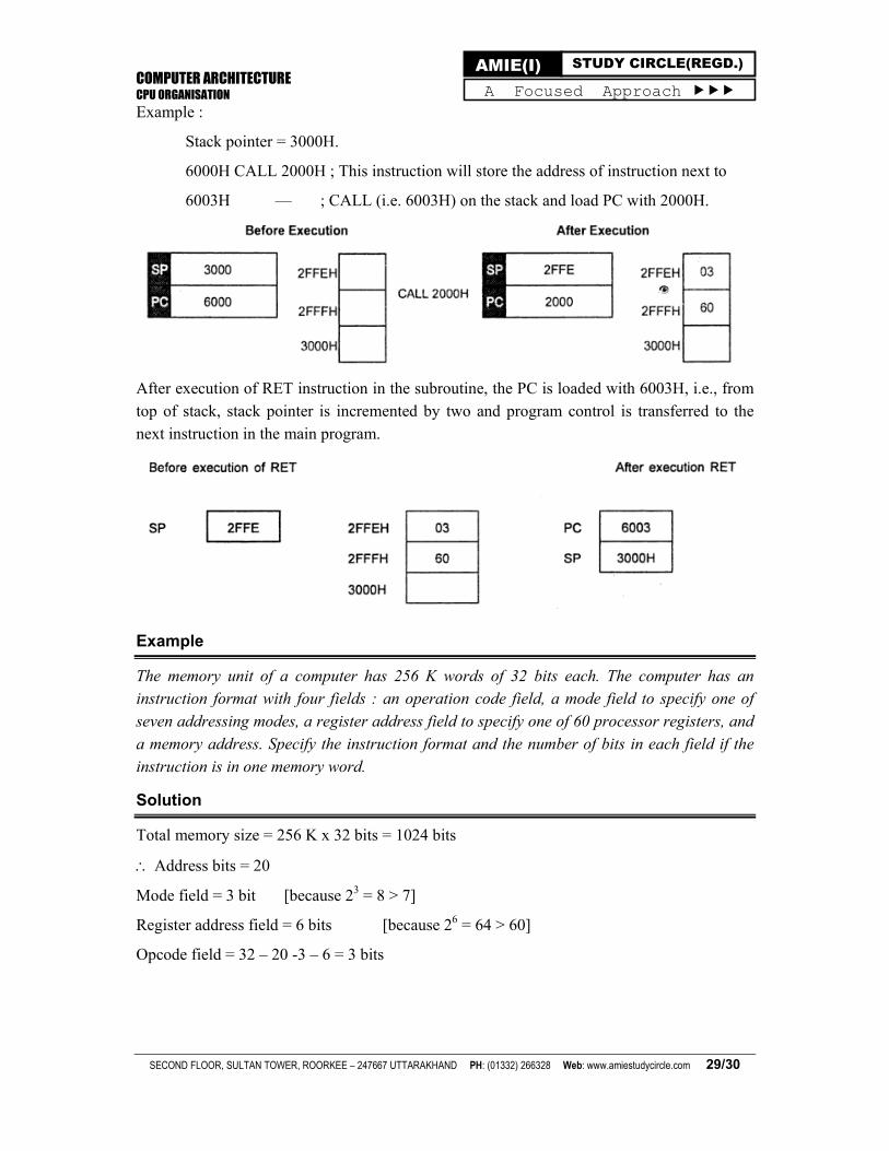
Example :
Stack pointer = 3000H.
6000H CALL 2000H ; This instruction will store the address of instruction next to
6003H — ; CALL (i.e. 6003H) on the stack and load PC with 2000H.
After execution of RET instruction in the subroutine, the PC is loaded with 6003H, i.e., from top of stack, stack pointer is incremented by two and program control is transferred to the next instruction in the main program.
Example
The memory unit of a computer has 256 K words of 32 bits each. The computer has an instruction format with four fields : an operation code field, a mode field to specify one of seven addressing modes, a register address field to specify one of 60 processor registers, and a memory address. Specify the instruction format and the number of bits in each field if the instruction is in one memory word.
Solution
Total memory size = 256 K x 32 bits = 1024 bits
Address bits = 20
Mode field = 3 bit [because 23 = 8 > 7]
Register address field = 6 bits [because 26 = 64 > 60]
Opcode field = 32 – 20 -3 – 6 = 3 bits
COMPUTER ARCHITECTURE CPU ORGANISATION
SECOND FLOOR, SULTAN TOWER, ROORKEE – 247667 UTTARAKHAND PH: (01332) 266328 Web: www.amiestudycircle.com 30/30
AMIE(I) STUDY CIRCLE(REGD.) A Focused Approach
ASSIGNMENT Q.1. (AMIE S11, W13, 5 marks): Write a short note on the stack organisation. How can it be implanted? Give example.
Q.2. (AMIE S15, 5 marks): How are stacks used for implementing subroutines? Explain with examples.
Q.3. (AMIE S11, 5 marks): What do you mean by instruction format? Explain with an example.
Q.4. (AMIE W14, 6 marks): What is an instruction code? How are different kinds of instructions interpreted?
Q.5. (AMIE S14, 10 marks): What is an instruction set architecture? Write different addressing modes of operands, which are used in an instruction, with appropriate examples.
Q.6. (AMIE S11, 10 marks): Discuss two different types of addressing modes with examples of their usage.
Q.7. (AMIE W14, 6 marks): What is the difference between zero-address, one-address and two-address instructions ? Illustrate with the help of examples.
Q.8. (AMIE S15, 7 marks): What are the advantages and disadvantages of using variable length instruction format? Explain the functions of various fields of an instruction format.
Q.9. (AMIE S12, W13, 8 marks): What is the difference between a direct and an indirect addressing mode of an operand? How many references to memory are needed for each addressing mode to bring an operand into a processor register?
Q.10. (AMIE W11, 14, 10 marks): What do you understand by addressing mode of an operand? What is the difference between relative and absolute addressing? Explain use of each mode using examples.
Q.11. (AMIE S15, 5 marks): What do you understand by addressing mode of an operand? Which is the type of addressing mode useful in adding 100 integer values stored in memory? Explain your answer.
Q.12. (AMIE W11, 5 marks): Suppose a computer supports fixed sized (16 bit) two operand instructions. Only register operands are supported, and two addressing modes are supported. There are 16 registers. What is the maximum number of instructions that the computer can support?
Q.13. (AMIE S12, 6 marks): A computer uses a memory unit with 256 K words of 32 bits each. Each instruction is stored in one word of memory. Each instruction has two operands- one register direct and one memory direct operand. The instruction has three parts : An operation code, a register code part to specify one of 64 registers, and an address part.
Q.14. (AMIE W14, 7 marks): A computer uses a memory unit with 128 MB word? of 64 bits each. A binary instruction code is stored in one word of memory. The instruction has four parts-some bits to differentiate between one of the four addressing modes supported by the system, an operation code, a register code part to specify one of the 512 registers and an address part. Draw the instruction word format and indicate the number of bits in each part
Q.15. (AMIE W11, 5 marks): What is the difference between accumulator architecture and general purpose register architecture? Why is general purpose register architecture considered advantageous?
Q.16. (AMIE S12, 6 marks): How many bits are there in the instruction operation code, the register code part, and the address part?
Q.17. (AMIE S12, 6 marks): Draw the instruction word format and indicate the number of bits in each part.
Q.18. (AMIE W13, 10 marks): Explain the fetch cycle of instruction execution with respect to the various micro-operations carried out by using a labelled block diagram of the CPU.
Q.19. (AMIE S14, 10 marks): Write a micro-routine to execute the following assembly language program:
ADD R1, R2, R3 (R1 R2 + R3)
where ADD is the op code for addition of contents of registers R2 and R3 and store the result in R1. Assume that there are 16 general purpose registers and 128 different operation codes available in the processor.
(For online support such as eBooks, video lectures, audio lectures, unsolved papers, quiz, test series and course updates, visit www.amiestudycircle.com)