Embed Size (px)
Citation preview
An ABB technical journal for Enclosures and
DIN rail Products users
1 |12
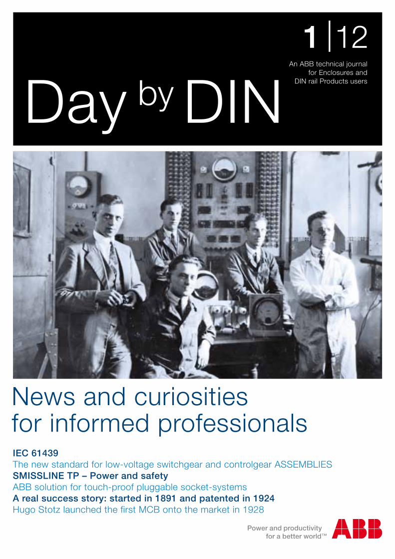
IEC 61439The new standard for low-voltage switchgear and controlgear ASSEMBLIESSMISSLINE TP – Power and safetyABB solution for touch-proof pluggable socket-systemsA real success story: started in 1891 and patented in 1924Hugo Stotz launched the first MCB onto the market in 1928
News and curiosities for informed professionals
Day by DIN
2 Day by DIN 1|12 Day by DIN 1|12
Editorial
Day by DIN 1 | 12 • An ABB technical journal for Enclosures and DIN rail Products users • copyright 2012 • Product Marketing Management: Emanuele Tosatti • E-mail: [email protected] • Published by: ABB S.p.A. - ABB SACE Division • Design: Winning Associati Printed by: Caleidograf • Use of the texts and the images without prior written authorisation by ABB S.p.A.- ABB SACE Division is prohibited
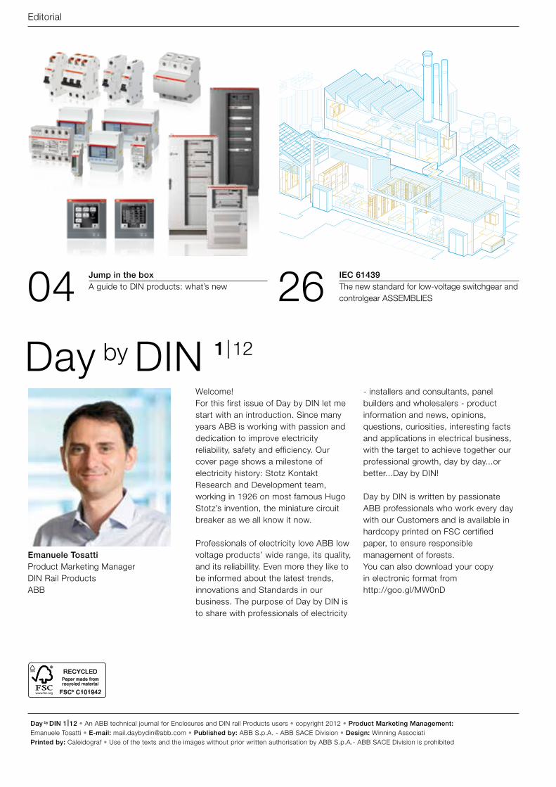
04 26Jump in the box A guide to DIN products: what’s new
IEC 61439 The new standard for low-voltage switchgear and controlgear ASSEMBLIES
Welcome! For this first issue of Day by DIN let me start with an introduction. Since many years ABB is working with passion and dedication to improve electricity reliability, safety and efficiency. Our cover page shows a milestone of electricity history: Stotz Kontakt Research and Development team, working in 1926 on most famous Hugo Stotz’s invention, the miniature circuit breaker as we all know it now.
Professionals of electricity love ABB low voltage products’ wide range, its quality, and its reliabillity. Even more they like to be informed about the latest trends, innovations and Standards in our business. The purpose of Day by DIN is to share with professionals of electricity
- installers and consultants, panel builders and wholesalers - product information and news, opinions, questions, curiosities, interesting facts and applications in electrical business, with the target to achieve together our professional growth, day by day...or better...Day by DIN!
Day by DIN is written by passionate ABB professionals who work every day with our Customers and is available in hardcopy printed on FSC certified paper, to ensure responsible management of forests. You can also download your copy in electronic format from http://goo.gl/MW0nD
Emanuele TosattiProduct Marketing Manager DIN Rail ProductsABB
Day by DIN 1 |12
Day by DIN 1|12 3Day by DIN 1|12
News and facts4 Jump in the box
A guide to DIN products: what’s new 12 In the news
Literature on our latest products18 Top five
Market classification19 Events
ABB at the Light+Building 2012
The expert answers20 Good morning DIN rail
The editor responds 32 Energy saving ideas
E250 latching relays38 Doktor Wise
The expert answers
Curiosity48 A short look at the meaning of lightning
through the ages49 Electric power and modernity:
new scenarios, new possibilities
Case History40 Environmental sensitivity and energy saving
Zero impact forwarding and logistics
Technical22 Precision of energy metering
Conforming to the MID Directive26 IEC 61439
The new standard for low-voltage switchgear and controlgear ASSEMBLIES
34 Urban legends Exploding the myths and reconsidering convictions
46 A world without electricity An imaginative picture to think of the future
50 Continuity of supply ABB APR high-immunity residual current devices offer excellent protection against unwanted tripping
58 Surge and lightning protection standard IEC / EN 62305 -1/ -2/ -3/ -4:2010
60 SMISSLINE TP – Power and safety ABB solution for touch-proof pluggable socket-systems
Report54 A real success story: Started in 1891 and
patented in 1924 Hugo Stotz launched the first MCB onto the market in 1928
Time to relax64 Connect the boxes66 Wall of fame
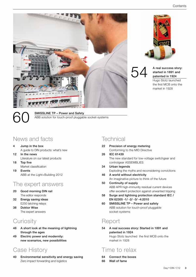
Contents
60
54
SMISSLINE TP – Power and SafetyABB solution for touch-proof pluggable socket-systems
A real success story: started in 1891 and patented in 1924Hugo Stotz launched the first MCB onto the market in 1928
4 Day by DIN 1|12 Day by DIN 1|12
News and facts
Jump in the boxABB’s newest products and solutions from Enclosures and DIN Rail Products world! In this issue new miniature circuit breakers, line protection devices, medical location solutions, new measuring devices and more.
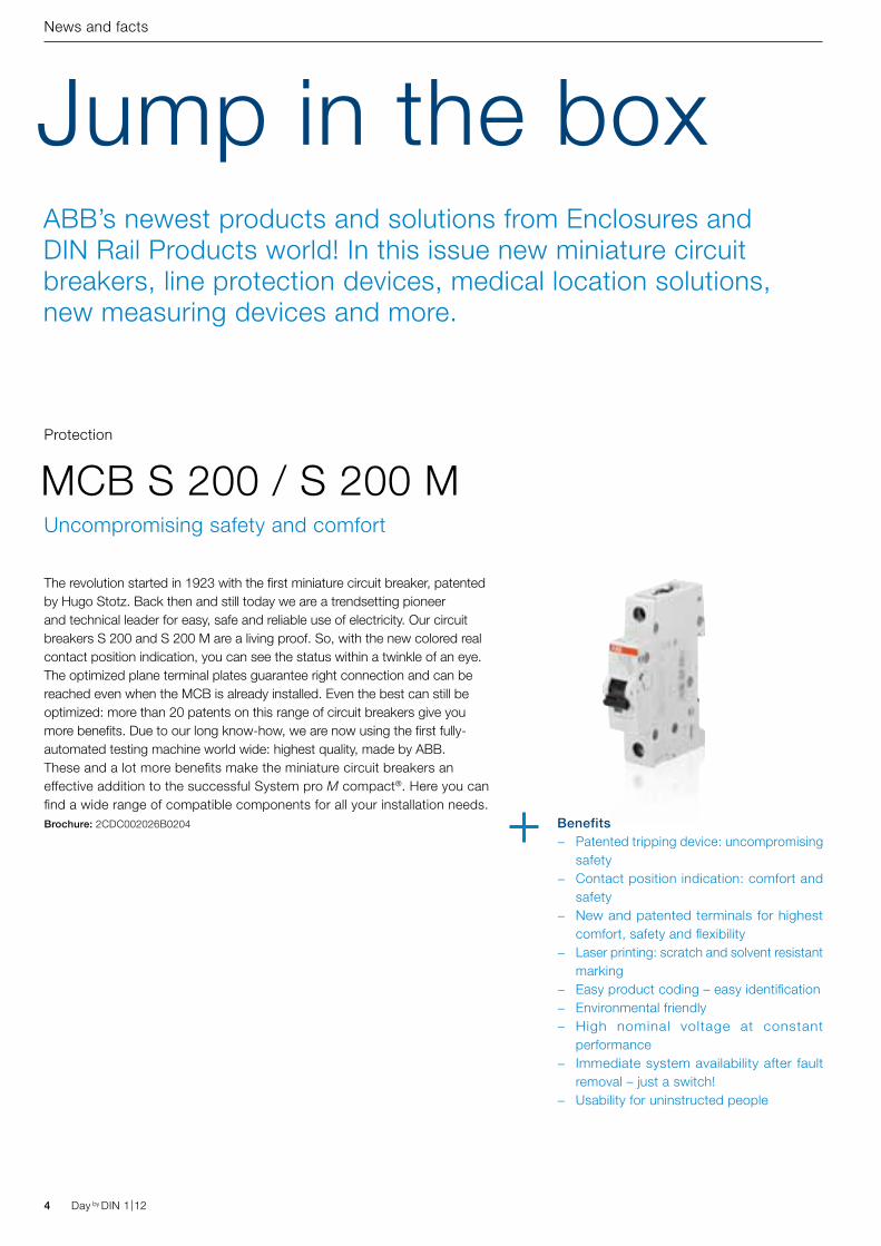
The revolution started in 1923 with the first miniature circuit breaker, patented by Hugo Stotz. Back then and still today we are a trendsetting pioneer and technical leader for easy, safe and reliable use of electricity. Our circuit breakers S 200 and S 200 M are a living proof. So, with the new colored real contact position indication, you can see the status within a twinkle of an eye. The optimized plane terminal plates guarantee right connection and can be reached even when the MCB is already installed. Even the best can still be optimized: more than 20 patents on this range of circuit breakers give you more benefits. Due to our long know-how, we are now using the first fully-automated testing machine world wide: highest quality, made by ABB.These and a lot more benefits make the miniature circuit breakers an effective addition to the successful System pro M compact®. Here you can find a wide range of compatible components for all your installation needs.Brochure: 2CDC002026B0204
MCB S 200 / S 200 MProtection
Uncompromising safety and comfort
Benefits − Patented tripping device: uncompromising
safety − Contact position indication: comfort and
safety − New and patented terminals for highest
comfort, safety and flexibility − Laser printing: scratch and solvent resistant
marking − Easy product coding – easy identification − Environmental friendly − High nominal voltage at constant
performance − Immediate system availability after fault
removal – just a switch! − Usability for uninstructed people
Day by DIN 1|12 5Day by DIN 1|12
News and facts
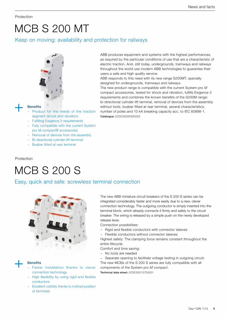
MCB S 200 MT
MCB S 200 S
Protection
Protection
Keep on moving: availability and protection for railways
Easy, quick and safe: screwless terminal connection
ABB produces equipment and systems with the highest performances, as required by the particular conditions of use that are a characteristic of electric traction. And, still today, undergrounds, tramways and railways throughout the world use modern ABB technologies to guarantee their users a safe and high quality service.ABB responds to this need with its new range S200MT, specially designed for undergrounds, tramways and railways.The new product range is compatible with the current System pro M compact accessories, tested for shock and vibration, fulfills Exigence 3 requirements and combines the known benefits of the S200M range:bi-directional cylinder-lift terminal, removal of devices from the assembly without tools, busbar fitted at rear terminal, several characteristics, number of poles and 10 kA breaking capacity acc. to IEC 60898-1.Catalogue: 2CDC002053D0203
The new ABB miniature circuit breakers of the S 200 S series can be integrated considerably faster and more easily due to a new, clever connection technology. The outgoing conductor is simply inserted into the terminal block, which already connects it firmly and safely to the circuit breaker. The wiring is released by a simple push on the newly developed release lever. Connection possibilities:
− Rigid and flexible conductors with connector sleeves − Flexible conductors without connector sleeves
Highest safety: The clamping force remains constant throughout the entire lifecycle.Comfort and time saving:
− No tools are needed − Separate opening to facilitate voltage testing in outgoing circuit.
The new MCBs of the S 200 S series are fully compatible with all components of the System pro M compact. Technical data sheet: 2CDC002137D0201
Benefits − Product for the needs of the traction
segment (shock and vibration) − Fulfilling Exigence 3 requirements − Fully compatible with the current System
pro M compact® accessories − Removal of devices from the assembly − Bi-directional cylinder-lift terminal − Busbar fitted at rear terminal
Benefits − Faster installation thanks to clever
connection technology − High flexibility by using rigid and flexible
conductors − Excellent visibility thanks to inclined position
of terminals
6 Day by DIN 1|12 Day by DIN 1|12
News and facts
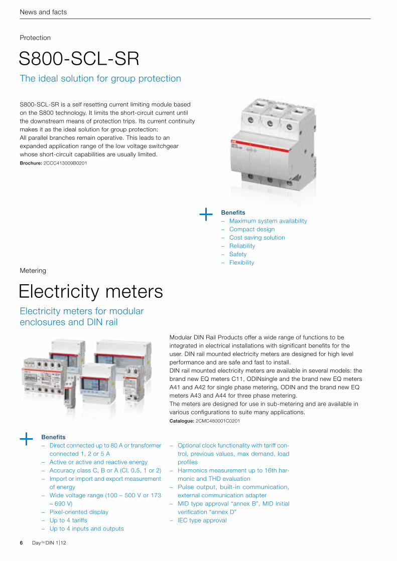
S800-SCL-SR is a self resetting current limiting module basedon the S800 technology. It limits the short-circuit current untilthe downstream means of protection trips. Its current continuitymakes it as the ideal solution for group protection:All parallel branches remain operative. This leads to anexpanded application range of the low voltage switchgearwhose short-circuit capabilities are usually limited.Brochure: 2CCC413009B0201
S800-SCL-SRProtection
Benefits − Maximum system availability − Compact design − Cost saving solution − Reliability − Safety − Flexibility
The ideal solution for group protection
Modular DIN Rail Products offer a wide range of functions to be integrated in electrical installations with significant benefits for the user. DIN rail mounted electricity meters are designed for high level performance and are safe and fast to install.DIN rail mounted electricity meters are available in several models: the brand new EQ meters C11, ODINsingle and the brand new EQ meters A41 and A42 for single phase metering, ODIN and the brand new EQ meters A43 and A44 for three phase metering.The meters are designed for use in sub-metering and are available in various configurations to suite many applications.Catalogue: 2CMC480001C0201
Electricity metersMetering
Electricity meters for modular enclosures and DIN rail
Benefits − Direct connected up to 80 A or transformer
connected 1, 2 or 5 A − Active or active and reactive energy − Accuracy class C, B or A (Cl. 0.5, 1 or 2) − Import or import and export measurement
of energy − Wide voltage range (100 – 500 V or 173
– 690 V) − Pixel-oriented display − Up to 4 tariffs − Up to 4 inputs and outputs
− Optional clock functionality with tariff con-trol, previous values, max demand, load profiles
− Harmonics measurement up to 16th har-monic and THD evaluation
− Pulse output, built-in communication, external communication adapter
− MID type approval “annex B”, MID initial verification “annex D”
− IEC type approval
Day by DIN 1|12 7Day by DIN 1|12
News and facts
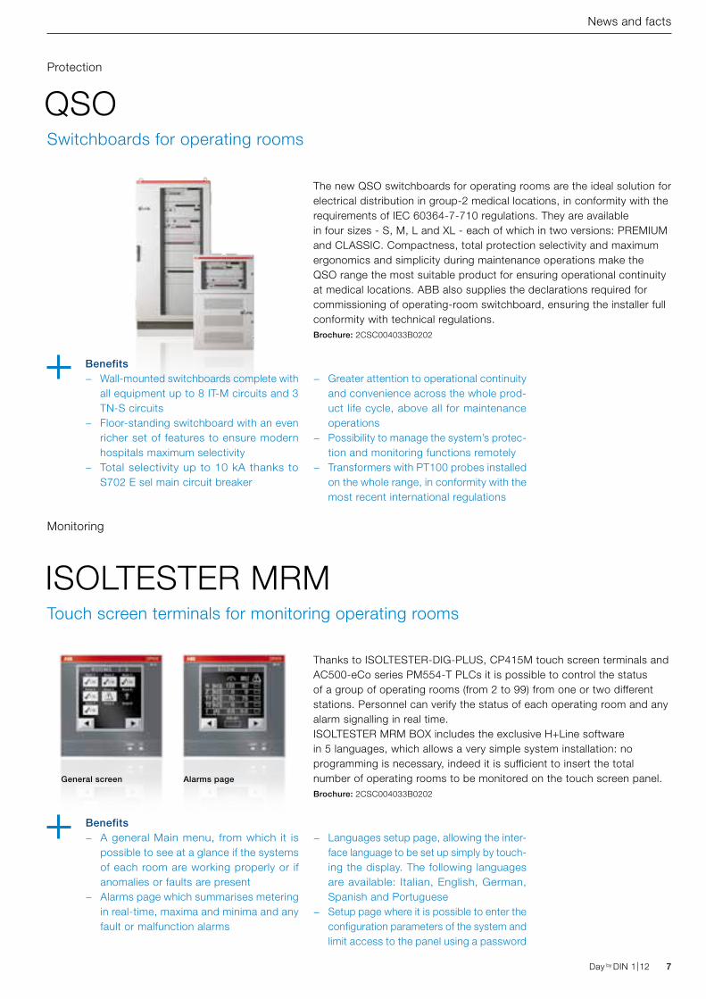
The new QSO switchboards for operating rooms are the ideal solution for electrical distribution in group-2 medical locations, in conformity with the requirements of IEC 60364-7-710 regulations. They are available in four sizes - S, M, L and XL - each of which in two versions: PREMIUM and CLASSIC. Compactness, total protection selectivity and maximum ergonomics and simplicity during maintenance operations make the QSO range the most suitable product for ensuring operational continuity at medical locations. ABB also supplies the declarations required for commissioning of operating-room switchboard, ensuring the installer full conformity with technical regulations.Brochure: 2CSC004033B0202
QSOProtection
Switchboards for operating rooms
Benefits − Wall-mounted switchboards complete with
all equipment up to 8 IT-M circuits and 3 TN-S circuits
− Floor-standing switchboard with an even richer set of features to ensure modern hospitals maximum selectivity
− Total selectivity up to 10 kA thanks to S702 E sel main circuit breaker
− Greater attention to operational continuity and convenience across the whole prod-uct life cycle, above all for maintenance operations
− Possibility to manage the system’s protec-tion and monitoring functions remotely
− Transformers with PT100 probes installed on the whole range, in conformity with the most recent international regulations
ISOLTESTER MRM
Monitoring
Touch screen terminals for monitoring operating rooms
Thanks to ISOLTESTER-DIG-PLUS, CP415M touch screen terminals and AC500-eCo series PM554-T PLCs it is possible to control the status of a group of operating rooms (from 2 to 99) from one or two different stations. Personnel can verify the status of each operating room and any alarm signalling in real time.ISOLTESTER MRM BOX includes the exclusive H+Line software in 5 languages, which allows a very simple system installation: no programming is necessary, indeed it is sufficient to insert the total number of operating rooms to be monitored on the touch screen panel.Brochure: 2CSC004033B0202
Benefits − A general Main menu, from which it is
possible to see at a glance if the systems of each room are working properly or if anomalies or faults are present
− Alarms page which summarises metering in real-time, maxima and minima and any fault or malfunction alarms
− Languages setup page, allowing the inter-face language to be set up simply by touch-ing the display. The following languages are available: Italian, English, German, Spanish and Portuguese
− Setup page where it is possible to enter the configuration parameters of the system and limit access to the panel using a password
General screen Alarms page
8 Day by DIN 1|12 Day by DIN 1|12
News and facts
E 90 PV fuseholders - UL listingProtection
Photovoltaic fuseholders listed according to UL Standards for US Market
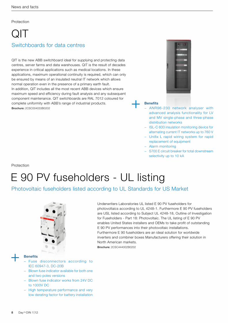
Underwriters Laboratories UL listed E 90 PV fuseholders for photovoltaics according to UL 4248-1. Furthermore E 90 PV fuseholders are USL listed according to Subject UL 4248-18, Outline of Investigation for Fuseholders - Part 18: Photovoltaic. The UL listing of E 90 PV enables United States installers and OEMs to take profit of outstanding E 90 PV performances into their photovoltaic installations. Furthermore E 90 fuseholders are an ideal solution for worldwide inverters and combiner boxes Manufacturers offering their solution in North American markets.Brochure: 2CSC444002B0202
Benefits − Fuse disconnectors according to
IEC 60947-3, DC-20B − Blown fuse indicator available for both one
and two poles versions − Blown fuse indicator works from 24V DC
to 1000V DC − High temperature performance and very
low derating factor for battery installation
QIT is the new ABB switchboard ideal for supplying and protecting data centres, server farms and data warehouses. QIT is the result of decades experience in critical applications such as medical locations. In these applications, maximum operational continuity is required, which can only be ensured by means of an insulated neutral IT network which allows normal operation even in the presence of a primary earth fault.In addition, QIT includes all the most recent ABB devices which ensure maximum speed and efficiency during fault analysis and any subsequent component maintenance. QIT switchboards are RAL 7012 coloured for complete uniformity with ABB’s range of industrial products.Brochure: 2CSC004033B0202
QITProtection
Switchboards for data centres
Benefits − ANR96-230 network analyser with
advanced analysis functionality for LV and MV single-phase and three-phase distribution networks
− ISL-C 600 insulation monitoring device for alternating current IT networks up to 760 V
− Unifix L rapid wiring system for rapid replacement of equipment
− Alarm monitoring − S700 E circuit breaker for total downstream
selectivity up to 10 kA
Day by DIN 1|12 9Day by DIN 1|12
News and facts
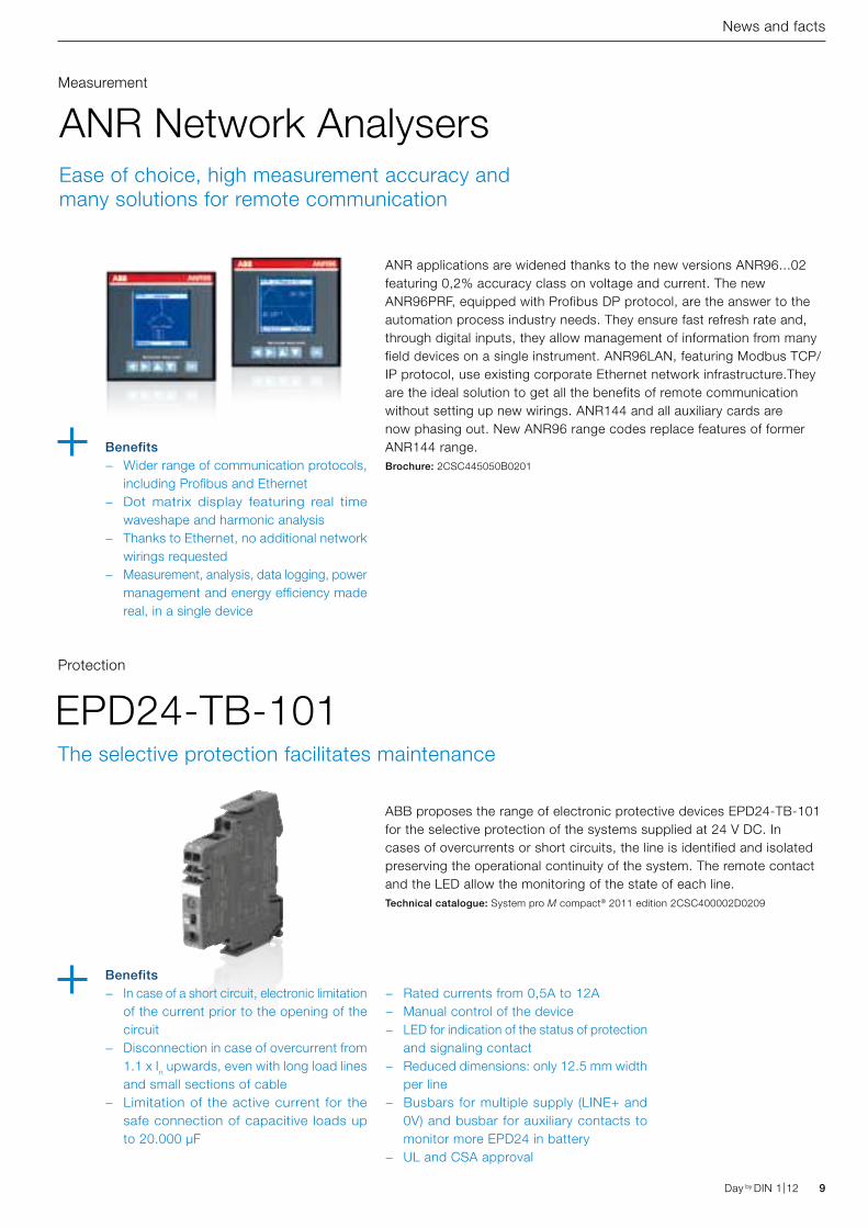
ANR applications are widened thanks to the new versions ANR96...02 featuring 0,2% accuracy class on voltage and current. The new ANR96PRF, equipped with Profibus DP protocol, are the answer to the automation process industry needs. They ensure fast refresh rate and, through digital inputs, they allow management of information from many field devices on a single instrument. ANR96LAN, featuring Modbus TCP/IP protocol, use existing corporate Ethernet network infrastructure.They are the ideal solution to get all the benefits of remote communication without setting up new wirings. ANR144 and all auxiliary cards are now phasing out. New ANR96 range codes replace features of former ANR144 range.Brochure: 2CSC445050B0201
ANR Network AnalysersMeasurement
Ease of choice, high measurement accuracy and many solutions for remote communication
Benefits − Wider range of communication protocols,
including Profibus and Ethernet − Dot matrix display featuring real time
waveshape and harmonic analysis − Thanks to Ethernet, no additional network
wirings requested − Measurement, analysis, data logging, power
management and energy efficiency made real, in a single device
ABB proposes the range of electronic protective devices EPD24-TB-101 for the selective protection of the systems supplied at 24 V DC. In cases of overcurrents or short circuits, the line is identified and isolated preserving the operational continuity of the system. The remote contact and the LED allow the monitoring of the state of each line.Technical catalogue: System pro M compact® 2011 edition 2CSC400002D0209
EPD24-TB-101Protection
Benefits − In case of a short circuit, electronic limitation
of the current prior to the opening of the circuit
− Disconnection in case of overcurrent from 1.1 x In upwards, even with long load lines and small sections of cable
− Limitation of the active current for the safe connection of capacitive loads up to 20.000 μF
The selective protection facilitates maintenance
− Rated currents from 0,5A to 12A − Manual control of the device − LED for indication of the status of protection
and signaling contact − Reduced dimensions: only 12.5 mm width
per line − Busbars for multiple supply (LINE+ and
0V) and busbar for auxiliary contacts to monitor more EPD24 in battery
− UL and CSA approval
10 Day by DIN 1|12
News and facts
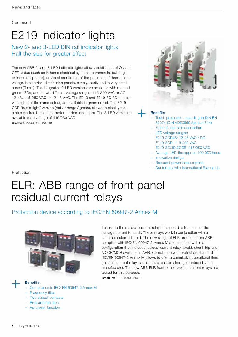
The new ABB 2- and 3-LED indicator lights allow visualisation of ON and OFF status (such as in home electrical systems, commercial buildings or industrial panels), or visual monitoring of the presence of three-phase voltage in electrical distribution panels, simply, easily and in very small space (9 mm). The integrated 2-LED versions are available with red and green LEDs, and in two different voltage ranges: 115-250 VAC or AC 12-48. 115-250 VAC or 12-48 VAC. The E219 and E219-3C-3D models, with lights of the same colour, are available in green or red. The E219-CDE “traffic-light” version (red / orange / green), allows to display the status of circuit breakers, motor starters and more. The 3-LED version is available for a voltage of 415/230 VAC.Brochure: 2CCC441002C0201
E219 indicator lightsCommand
New 2- and 3-LED DIN rail indicator lights Half the size for greater effect
Benefits − Touch protection according to DIN EN
50274 (DIN VDE0660 Section 514) − Ease of use, safe connection − LED voltage ranges:
E219-2CD48: 12-48 VAC / DC E219-2CD: 115-250 VAC E219-3C,3D,3CDE: 415/250 VAC
− Average LED life: approx. 100,000 hours − Innovative design − Reduced power consumption − Conformity with International Standards
ELR: ABB range of front panel residual current relays
Protection
Protection device according to IEC/EN 60947-2 Annex M
Thanks to the residual current relays it is possible to measure the leakage current to earth. These relays work in conjunction with a separate external toroid. The new range of ELR products from ABB complies with IEC/EN 60947-2 Annex M and is tested within a configuration that includes residual current relay, toroid, shunt-trip and MCCB/MCB available in ABB. Compliance with protection standard IEC/EN 60947-2 Annex M allows to offer a cumulative operational time (residual current relay, shunt-trip, circuit breaker) guaranteed by the manufacturer. The new ABB ELR front panel residual current relays are tested for this purpose.Brochure: 2CSC444050B0201
Benefits − Compliance to IEC/ EN 60947-2 Annex M − Frequency filter − Two output contacts − Prealarm function − Autoreset function
Day by DIN 1|12
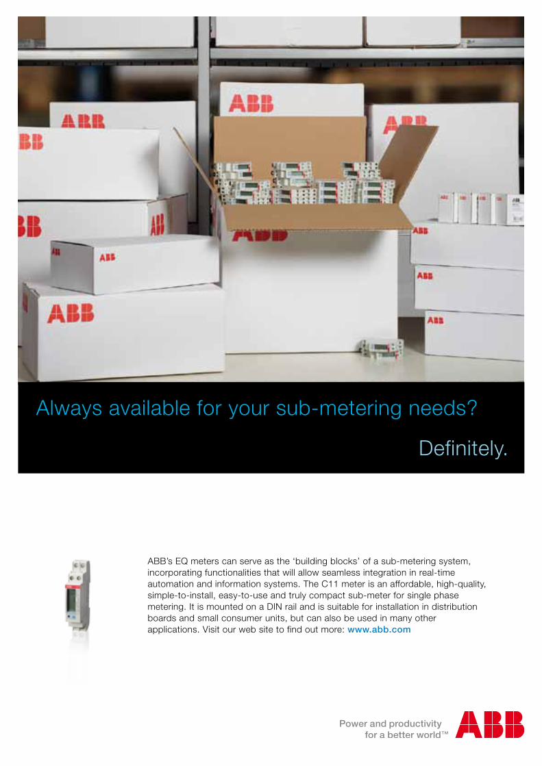
Always available for your sub-metering needs?
Definitely.
ABB’s EQ meters can serve as the ‘building blocks’ of a sub-metering system, incorporating functionalities that will allow seamless integration in real-time automation and information systems. The C11 meter is an affordable, high-quality, simple-to-install, easy-to-use and truly compact sub-meter for single phase metering. It is mounted on a DIN rail and is suitable for installation in distribution boards and small consumer units, but can also be used in many other applications. Visit our web site to find out more: www.abb.com
Easy, quick and safe!Screwless MCB S 200 S
12 Day by DIN 1|12 Day by DIN 1|12
News and facts
In the newsDistribution and measurement, disconnection and protection: lots of new documents by ABB for those operating in the electrical business, helping them in their work.The documents and the software can be downloaded from http://www.abb.com/abblibrary/DownloadCenter/
Protection
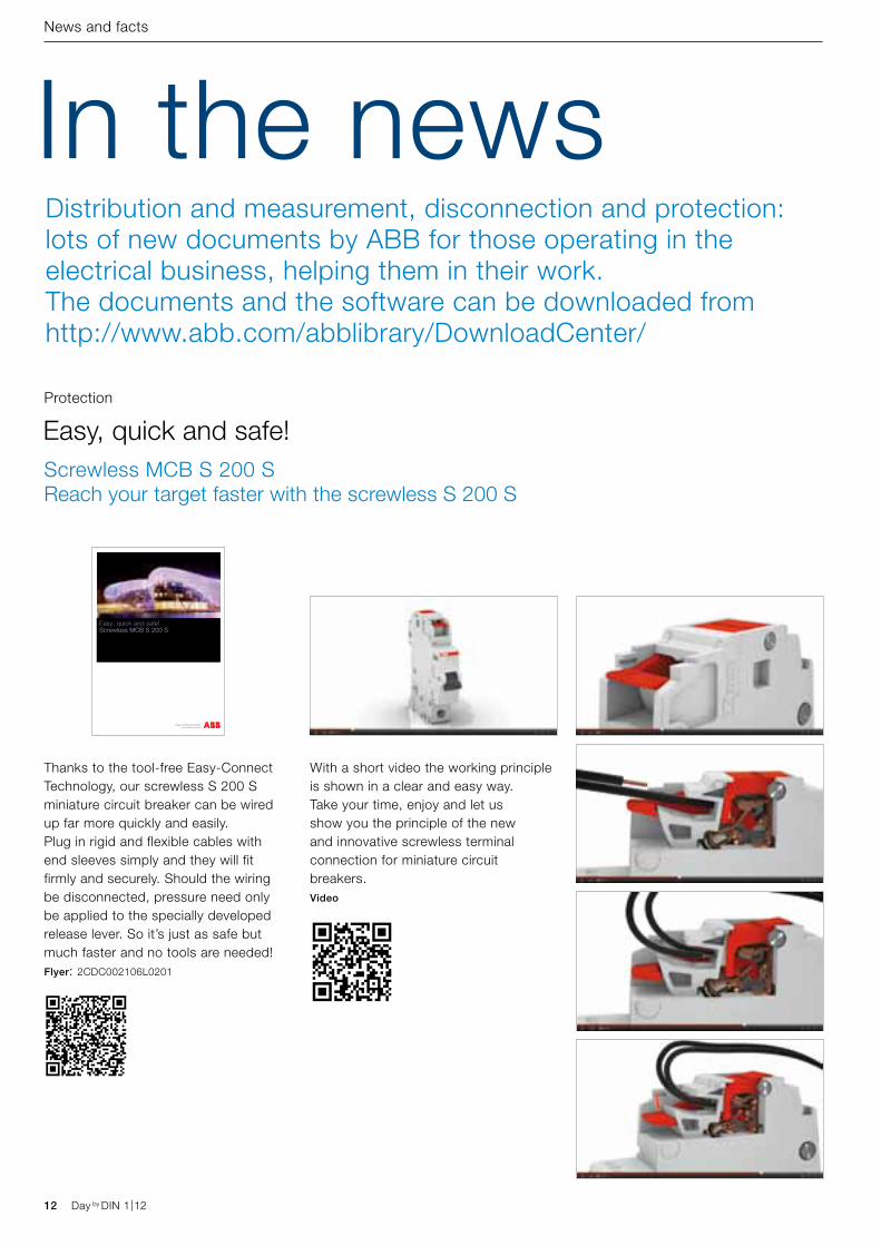
Thanks to the tool-free Easy-Connect Technology, our screwless S 200 S miniature circuit breaker can be wired up far more quickly and easily.Plug in rigid and flexible cables with end sleeves simply and they will fit firmly and securely. Should the wiring be disconnected, pressure need only be applied to the specially developed release lever. So it’s just as safe but much faster and no tools are needed!Flyer: 2CDC002106L0201
Easy, quick and safe!Screwless MCB S 200 S Reach your target faster with the screwless S 200 S
With a short video the working principle is shown in a clear and easy way. Take your time, enjoy and let us show you the principle of the new and innovative screwless terminal connection for miniature circuit breakers.Video
Short-circuit current limiterS800-SCL-SR Electricity meters
for increased awareness
Brochure
Day by DIN 1|12 13Day by DIN 1|12
News and facts
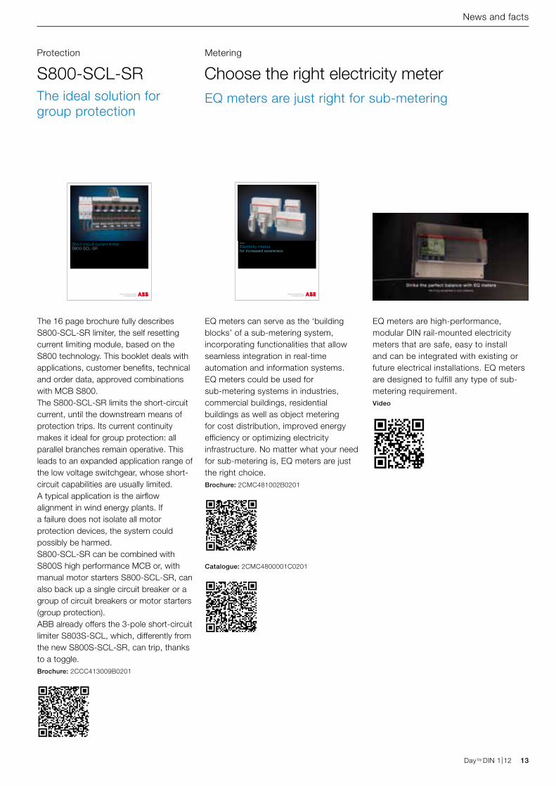
The 16 page brochure fully describes S800-SCL-SR limiter, the self resetting current limiting module, based on the S800 technology. This booklet deals with applications, customer benefits, technical and order data, approved combinations with MCB S800.The S800-SCL-SR limits the short-circuit current, until the downstream means of protection trips. Its current continuity makes it ideal for group protection: all parallel branches remain operative. This leads to an expanded application range of the low voltage switchgear, whose short-circuit capabilities are usually limited. A typical application is the airflow alignment in wind energy plants. If a failure does not isolate all motor protection devices, the system could possibly be harmed.S800-SCL-SR can be combined with S800S high performance MCB or, with manual motor starters S800-SCL-SR, can also back up a single circuit breaker or a group of circuit breakers or motor starters (group protection).ABB already offers the 3-pole short-circuit limiter S803S-SCL, which, differently from the new S800S-SCL-SR, can trip, thanks to a toggle. Brochure: 2CCC413009B0201
S800-SCL-SRProtection
The ideal solution for group protection
EQ meters are high-performance, modular DIN rail-mounted electricity meters that are safe, easy to install and can be integrated with existing or future electrical installations. EQ meters are designed to fulfill any type of sub-metering requirement.Video
EQ meters can serve as the ‘building blocks’ of a sub-metering system, incorporating functionalities that allow seamless integration in real-time automation and information systems. EQ meters could be used for sub-metering systems in industries, commercial buildings, residential buildings as well as object metering for cost distribution, improved energy efficiency or optimizing electricity infrastructure. No matter what your need for sub-metering is, EQ meters are just the right choice.Brochure: 2CMC481002B0201
Catalogue: 2CMC4800001C0201
Choose the right electricity meterMetering
EQ meters are just right for sub-metering
IEC 61439The new standard for low-voltage switchgear and controlgear AssEMBLIEs
11 | 2010
ELR: ABB range of front panel residual current relaysProtection device according to IEC/EN 60947-2 Annex M
Switching off instead of blowingMake profits with miniature circuit breakers
14 Day by DIN 1|12 Day by DIN 1|12
News and facts
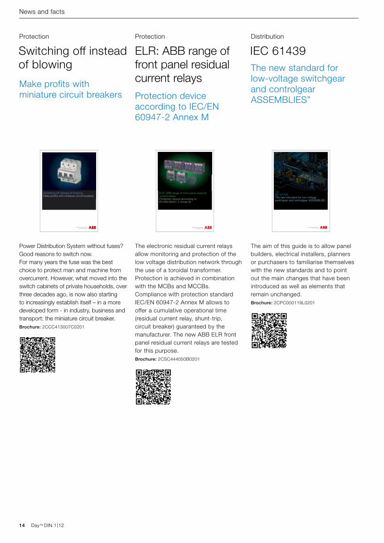
The aim of this guide is to allow panel builders, electrical installers, planners or purchasers to familiarise themselves with the new standards and to point out the main changes that have been introduced as well as elements that remain unchanged.Brochure: 2CPC000119L0201
IEC 61439Distribution
The new standard for low-voltage switchgear and controlgear ASSEMBLIES”
The electronic residual current relays allow monitoring and protection of the low voltage distribution network through the use of a toroidal transformer. Protection is achieved in combination with the MCBs and MCCBs.Compliance with protection standard IEC/EN 60947-2 Annex M allows to offer a cumulative operational time (residual current relay, shunt-trip, circuit breaker) guaranteed by the manufacturer. The new ABB ELR front panel residual current relays are tested for this purpose.Brochure: 2CSC444050B0201
ELR: ABB range of front panel residual current relays
Protection
Protection device according to IEC/EN 60947-2 Annex M
Power Distribution System without fuses? Good reasons to switch now. For many years the fuse was the best choice to protect man and machine from overcurrent. However, what moved into the switch cabinets of private households, over three decades ago, is now also starting to increasingly establish itself – in a more developed form - in industry, business and transport: the miniature circuit breaker. Brochure: 2CCC413007C0201
Switching off instead of blowing
Protection
Make profits with miniature circuit breakers
Operational continuitySafety and reliability of ABB H+Line, switchboards and devices for group 2 medical locations
Power and productivity for a better worldTM ABB
E 210 product range E 219 multiple indicator lightsSystem pro M compact ®
Time, staircase lighting, twilight switches and thermostatsSolutions for comfort, energy saving and simple automations.
Day by DIN 1|12 15Day by DIN 1|12
News and facts
Protection Command Control
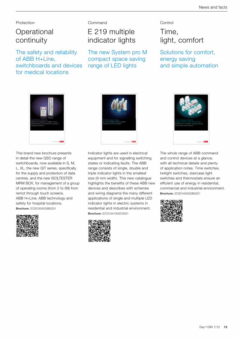
This brand new brochure presents in detail the new QSO range of switchboards, now available in S, M, L, XL, the new QIT series, specifically for the supply and protection of data centres, and the new ISOLTESTER MRM BOX, for management of a group of operating rooms (from 2 to 99) from remot through touch screens. ABB H+Line: ABB technology and safety for hospital locations.Brochure: 2CSC004033B0201
Indicator lights are used in electrical equipment and for signalling switching states or indicating faults. The ABB range consists of single, double and triple indicator lights in the smallest size (9 mm width). This new catalogue highlights the benefits of these ABB new devices and describes with schemes and wiring diagrams the many different applications of single and multiple LED indicator lights in electric systems in residential and industrial environment.Brochure: 2CCC441002C0201
The whole range of ABB command and control devices at a glance, with all technical details and plenty of application notes. Time switches, twilight switches, staircase light switches and thermostats ensure an efficient use of energy in residential, commercial and industrial environment.Brochure: 2CSC440020B0201
Operational continuity
E 219 multiple indicator lights
Time, light, comfort
The safety and reliability of ABB H+Line, switchboards and devices for medical locations
The new System pro M compact space saving range of LED lights
Solutions for comfort, energy saving and simple automation
Mad
e to measure. P
ractical guide to electrical m
easurements in low
voltage switchb
oards
(a)
(b)V
t
V
t
(f)50 Hz
A
050
100
150
200250 500
A
050
100
150
200250 500
V
0
8060
40
20
Made to measure.Practical guide to electrical measurements in low voltage switchboards
2CS
C44
5012
D02
01 -
12/
2010
- 1
.500
- C
AL.
Contact us
ABB SACEUna divisione di ABB S.p.A.Apparecchi ModulariViale dell’Industria, 1820010 Vittuone (MI)Tel.: 02 9034 1Fax: 02 9034 7609
bol.it.abb.comwww.abb.com
The data and illustrations are not binding. We reserve the right to modify the contents of this document on the basis of technical development of the products,without prior notice.
Copyright 2010 ABB. All rights reserved.
Multimeters and network analyzersFully monitored installations
16 Day by DIN 1|12 Day by DIN 1|12
News and facts
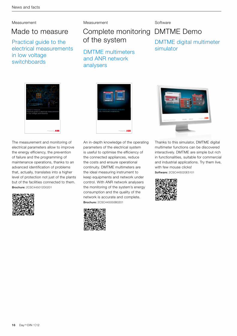
Thanks to this simulator, DMTME digital multimeter functions can be discovered interactively. DMTME are simple but rich in functionalities, suitable for commercial and industrial applications. Try them live, with few mouse clicks!Software: 2CSC445020E5101
DMTME DemoSoftware
DMTME digital multimeter simulator
An in-depth knowledge of the operating parameters of the electrical system is useful to optimise the efficiency of the connected appliances, reduce the costs and ensure operational continuity. DMTME multimeters are the ideal measuring instrument to keep equipments and network under control. With ANR network analysers the monitoring of the system’s energy consumption and the quality of the network is accurate and complete.Brochure: 2CSC445050B0201
Complete monitoring of the system
Measurement
The measurement and monitoring of electrical parameters allow to improve the energy efficiency, the prevention of failure and the programming of maintenance operations, thanks to an advanced identification of problems that, actually, translates into a higher level of protection not just of the plants but of the facilities connected to them.Brochure: 2CSC445012D0201
Made to measureMeasurement
Practical guide to the electrical measurements in low voltage switchboards
DMTME multimeters and ANR network analysers
Day by DIN 1|12 17Day by DIN 1|12
News and facts
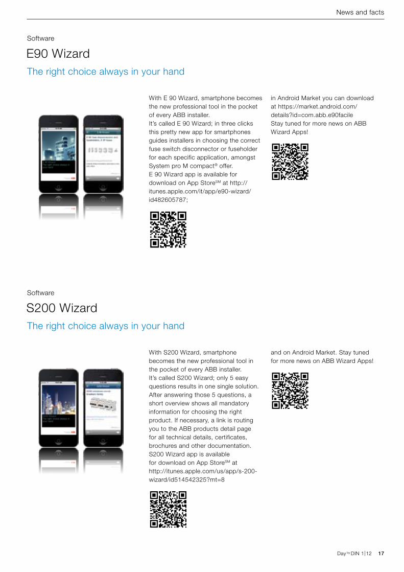
With E 90 Wizard, smartphone becomes the new professional tool in the pocket of every ABB installer.It’s called E 90 Wizard; in three clicks this pretty new app for smartphones guides installers in choosing the correct fuse switch disconnector or fuseholder for each specific application, amongst System pro M compact® offer.E 90 Wizard app is available for download on App StoreSM at http://itunes.apple.com/it/app/e90-wizard/id482605787;
With S200 Wizard, smartphone becomes the new professional tool in the pocket of every ABB installer.It’s called S200 Wizard; only 5 easy questions results in one single solution. After answering those 5 questions, a short overview shows all mandatory information for choosing the right product. If necessary, a link is routing you to the ABB products detail page for all technical details, certificates, brochures and other documentation.S200 Wizard app is available for download on App StoreSM at http://itunes.apple.com/us/app/s-200-wizard/id514542325?mt=8
E90 Wizard
S200 Wizard
Software
Software
The right choice always in your hand
The right choice always in your hand
in Android Market you can download at https://market.android.com/details?id=com.abb.e90facileStay tuned for more news on ABB Wizard Apps!
and on Android Market. Stay tuned for more news on ABB Wizard Apps!
18 Day by DIN 1|12 Day by DIN 1|12
News and facts
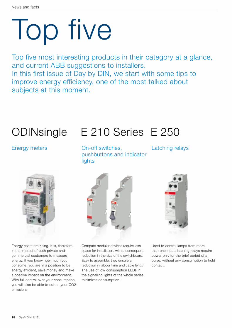
Top fiveTop five most interesting products in their category at a glance, and current ABB suggestions to installers. In this first issue of Day by DIN, we start with some tips to improve energy efficiency, one of the most talked about subjects at this moment.
Compact modular devices require less space for installation, with a consequent reduction in the size of the switchboard. Easy to assemble, they ensure a reduction in labour time and cable length.The use of low consumption LEDs in the signalling lights of the whole series minimizes consumption.
E 210 Series
Used to control lamps from more than one input, latching relays require power only for the brief period of a pulse, without any consumption to hold contact.
E 250Latching relaysOn-off switches,
pushbuttons and indicator lights
Energy costs are rising. It is, therefore, in the interest of both private and commercial customers to measure energy. If you know how much you consume, you are in a position to be energy efficient, save money and make a positive impact on the environment. With full control over your consumption, you will also be able to cut on your CO2 emissions.
ODINsingleEnergy meters
Events
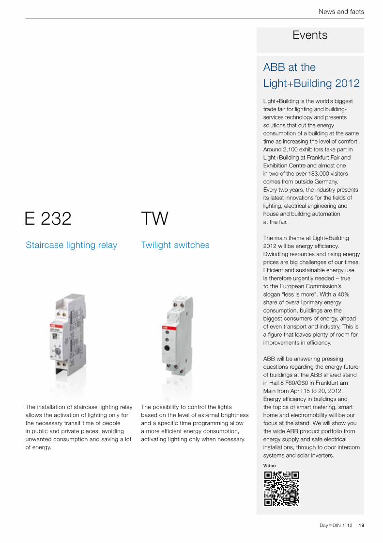
ABB at the Light+Building 2012Light+Building is the world’s biggest trade fair for lighting and building-services technology and presents solutions that cut the energy consumption of a building at the same time as increasing the level of comfort. Around 2,100 exhibitors take part in Light+Building at Frankfurt Fair and Exhibition Centre and almost one in two of the over 183,000 visitors comes from outside Germany. Every two years, the industry presents its latest innovations for the fields of lighting, electrical engineering and house and building automation at the fair.
The main theme at Light+Building 2012 will be energy efficiency. Dwindling resources and rising energy prices are big challenges of our times. Efficient and sustainable energy use is therefore urgently needed – true to the European Commission’s slogan “less is more”. With a 40% share of overall primary energy consumption, buildings are the biggest consumers of energy, ahead of even transport and industry. This is a figure that leaves plenty of room for improvements in efficiency.
ABB will be answering pressing questions regarding the energy future of buildings at the ABB shared stand in Hall 8 F60/G60 in Frankfurt am Main from April 15 to 20, 2012. Energy efficiency in buildings and the topics of smart metering, smart home and electromobility will be our focus at the stand. We will show you the wide ABB product portfolio from energy supply and safe electrical installations, through to door intercom systems and solar inverters.
Video
Day by DIN 1|12 19Day by DIN 1|12
News and facts
The possibility to control the lights based on the level of external brightness and a specific time programming allow a more efficient energy consumption, activating lighting only when necessary.
TWTwilight switches
The installation of staircase lighting relay allows the activation of lighting only for the necessary transit time of people in public and private places, avoiding unwanted consumption and saving a lot of energy.
E 232Staircase lighting relay
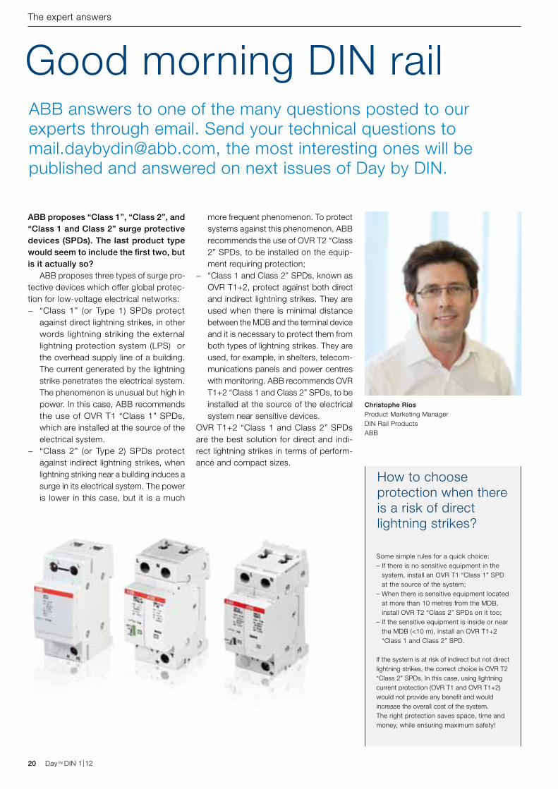
Some simple rules for a quick choice:– If there is no sensitive equipment in the
system, install an OVR T1 “Class 1” SPD at the source of the system;
– When there is sensitive equipment located at more than 10 metres from the MDB, install OVR T2 “Class 2” SPDs on it too;
– If the sensitive equipment is inside or near the MDB (<10 m), install an OVR T1+2 “Class 1 and Class 2” SPD.
If the system is at risk of indirect but not direct lightning strikes, the correct choice is OVR T2 “Class 2” SPDs. In this case, using lightning current protection (OVR T1 and OVR T1+2) would not provide any benefit and would increase the overall cost of the system.The right protection saves space, time and money, while ensuring maximum safety!
How to choose protection when there is a risk of direct lightning strikes?
20 Day by DIN 1|12
The expert answers
ABB proposes “Class 1”, “Class 2”, and “Class 1 and Class 2” surge protective devices (SPDs). The last product type would seem to include the first two, but is it actually so? ABB proposes three types of surge pro-tective devices which offer global protec-tion for low-voltage electrical networks:
− “Class 1” (or Type 1) SPDs protect against direct lightning strikes, in other words lightning striking the external lightning protection system (LPS) or the overhead supply line of a building. The current generated by the lightning strike penetrates the electrical system. The phenomenon is unusual but high in power. In this case, ABB recommends the use of OVR T1 “Class 1” SPDs, which are installed at the source of the electrical system.
− “Class 2” (or Type 2) SPDs protect against indirect lightning strikes, when lightning striking near a building induces a surge in its electrical system. The power is lower in this case, but it is a much
more frequent phenomenon. To protect systems against this phenomenon, ABB recommends the use of OVR T2 “Class 2” SPDs, to be installed on the equip-ment requiring protection;
− “Class 1 and Class 2” SPDs, known as OVR T1+2, protect against both direct and indirect lightning strikes. They are used when there is minimal distance between the MDB and the terminal device and it is necessary to protect them from both types of lightning strikes. They are used, for example, in shelters, telecom-munications panels and power centres with monitoring. ABB recommends OVR T1+2 “Class 1 and Class 2” SPDs, to be installed at the source of the electrical system near sensitive devices.
OVR T1+2 “Class 1 and Class 2” SPDs are the best solution for direct and indi-rect lightning strikes in terms of perform-ance and compact sizes.
Good morning DIN rail
Christophe RiosProduct Marketing Manager DIN Rail ProductsABB
ABB answers to one of the many questions posted to our experts through email. Send your technical questions to [email protected], the most interesting ones will be published and answered on next issues of Day by DIN.
Day by DIN 1|12
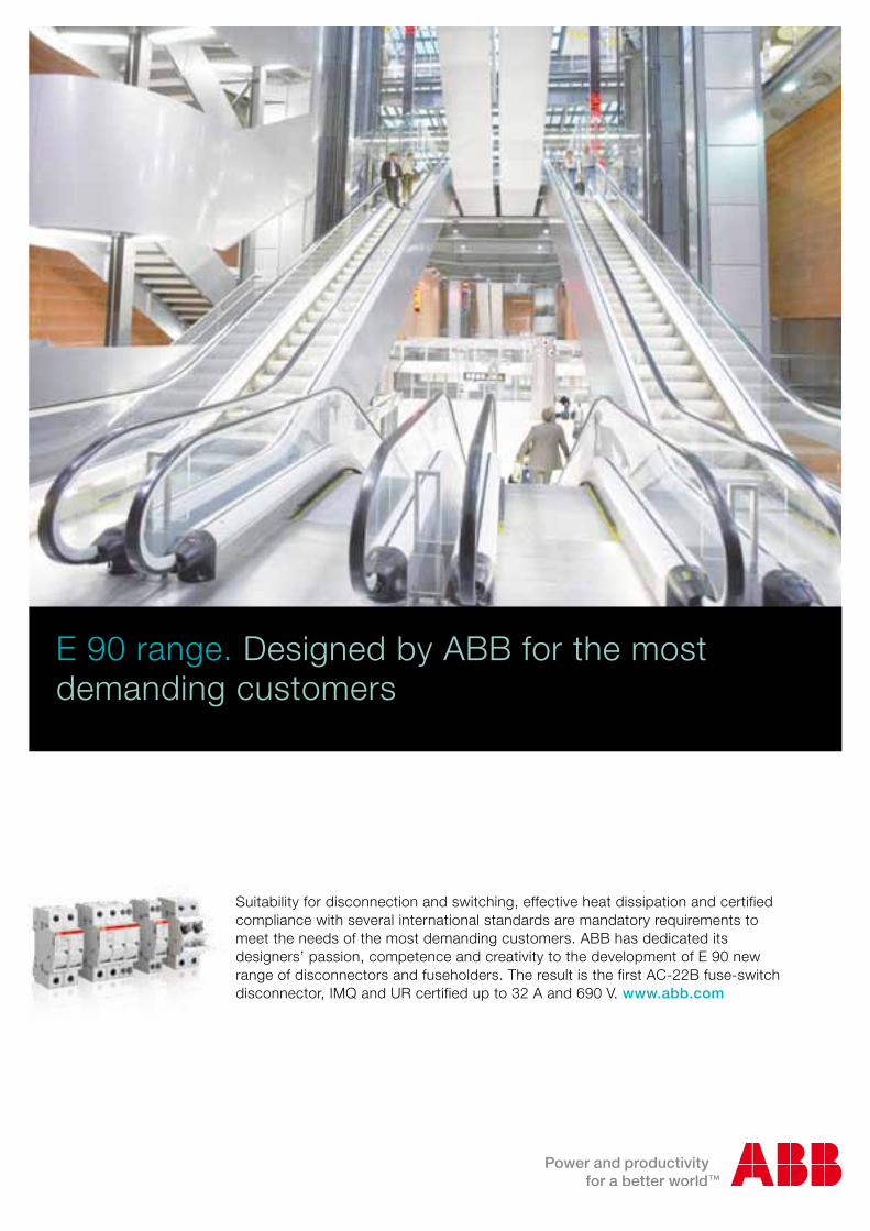
E 90 range. Designed by ABB for the most demanding customers
Suitability for disconnection and switching, effective heat dissipation and certified compliance with several international standards are mandatory requirements to meet the needs of the most demanding customers. ABB has dedicated its designers’ passion, competence and creativity to the development of E 90 new range of disconnectors and fuseholders. The result is the first AC-22B fuse-switch disconnector, IMQ and UR certified up to 32 A and 690 V. www.abb.com
22 Day by DIN 1|12 Day by DIN 1|12
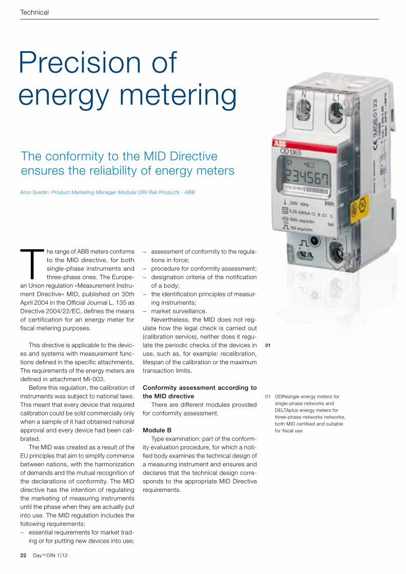
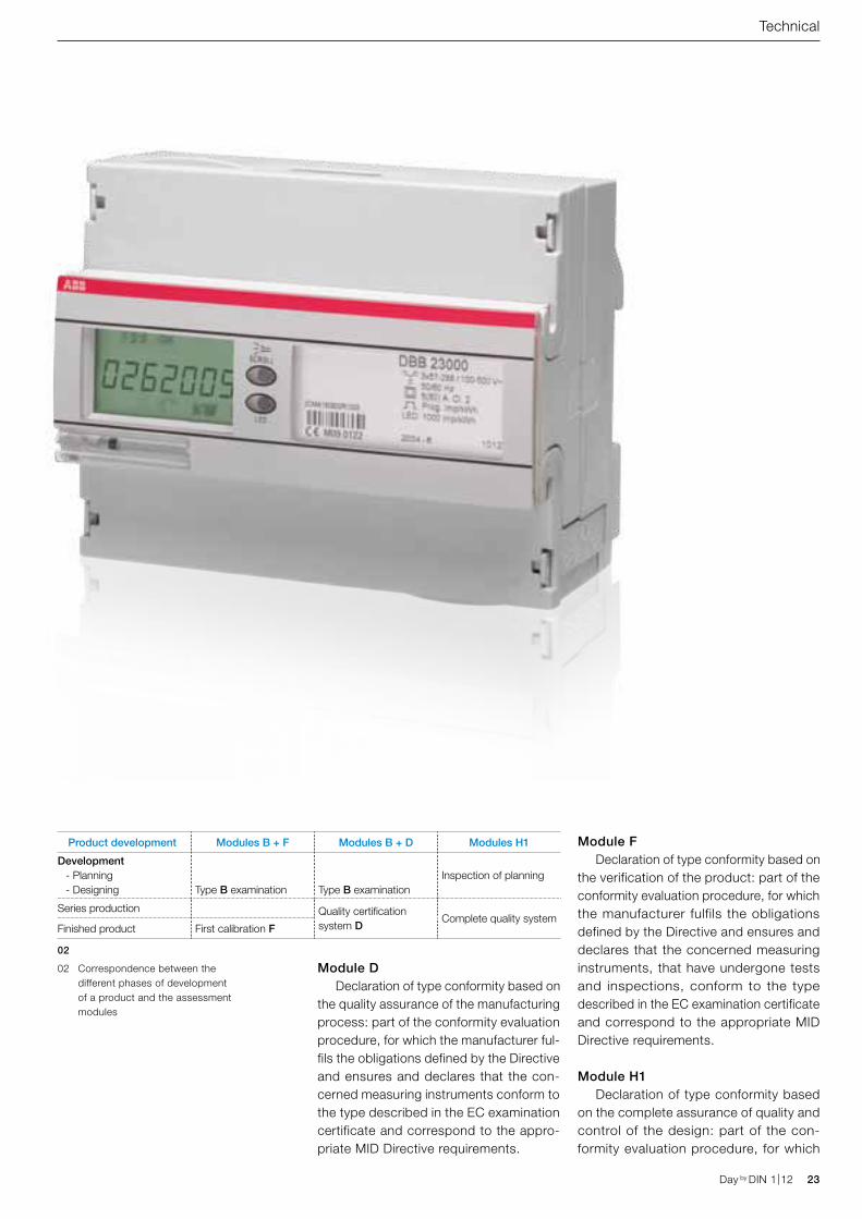
Precision of energy metering
The conformity to the MID Directive ensures the reliability of energy meters
The range of ABB meters conforms to the MID directive, for both single-phase instruments and three-phase ones. The Europe-
an Union regulation «Measurement Instru-ment Directive» MID, published on 30th April 2004 in the Official Journal L. 135 as Directive 2004/22/EC, defines the means of certification for an energy meter for fiscal metering purposes.
This directive is applicable to the devic-es and systems with measurement func-tions defined in the specific attachments. The requirements of the energy meters are defined in attachment MI-003. Before this regulation, the calibration of instruments was subject to national laws. This meant that every device that required calibration could be sold commercially only when a sample of it had obtained national approval and every device had been cali-brated. The MID was created as a result of the EU principles that aim to simplify commerce between nations, with the harmonization of demands and the mutual recognition of the declarations of conformity. The MID directive has the intention of regulating the marketing of measuring instruments until the phase when they are actually put into use. The MID regulation includes the following requirements:
− essential requirements for market trad-ing or for putting new devices into use;
− assessment of conformity to the regula-tions in force;
− procedure for conformity assessment; − designation criteria of the notification
of a body; − the identification principles of measur-
ing instruments; − market surveillance.
Nevertheless, the MID does not reg-ulate how the legal check is carried out (calibration service), neither does it regu-late the periodic checks of the devices in use, such as, for example: recalibration, lifespan of the calibration or the maximum transaction limits.
Conformity assessment according to the MID directive There are different modules provided for conformity assessment.
Module B Type examination: part of the conform-ity evaluation procedure, for which a noti-fied body examines the technical design of a measuring instrument and ensures and declares that the technical design corre-sponds to the appropriate MID Directive requirements.
Technical
01 ODINsingle energy meters for single-phase networks and DELTAplus energy meters for three-phase networks networks, both MID certifiied and suitable for fiscal use
01
Aron Svedin: Product Marketing Manager Modular DIN Rail Products - ABB
Day by DIN 1|12 23Day by DIN 1|12
Module D Declaration of type conformity based on the quality assurance of the manufacturing process: part of the conformity evaluation procedure, for which the manufacturer ful-fils the obligations defined by the Directive and ensures and declares that the con-cerned measuring instruments conform to the type described in the EC examination certificate and correspond to the appro-priate MID Directive requirements.
Module F Declaration of type conformity based on the verification of the product: part of the conformity evaluation procedure, for which the manufacturer fulfils the obligations defined by the Directive and ensures and declares that the concerned measuring instruments, that have undergone tests and inspections, conform to the type described in the EC examination certificate and correspond to the appropriate MID Directive requirements.
Module H1 Declaration of type conformity based on the complete assurance of quality and control of the design: part of the con-formity evaluation procedure, for which
Technical
Product development Modules B + F Modules B + D Modules H1
Development - Planning - Designing Type B examination Type B examination
Inspection of planning
Series production Quality certification system D
Complete quality systemFinished product First calibration F
02
02 Correspondence between the different phases of development of a product and the assessment modules
DAB 130073x57-280/100-500V50/60Hz
1 (6)A CI B (CI.1)Prog Imp/kWh
LED 5000 Imp/kWhTb 72 -40C to 55C
2010 - 33 1001
2CMA139305R1000
0122M10
1 2 3 41716
15 14 13 12 11 10 9 8 7 6 5
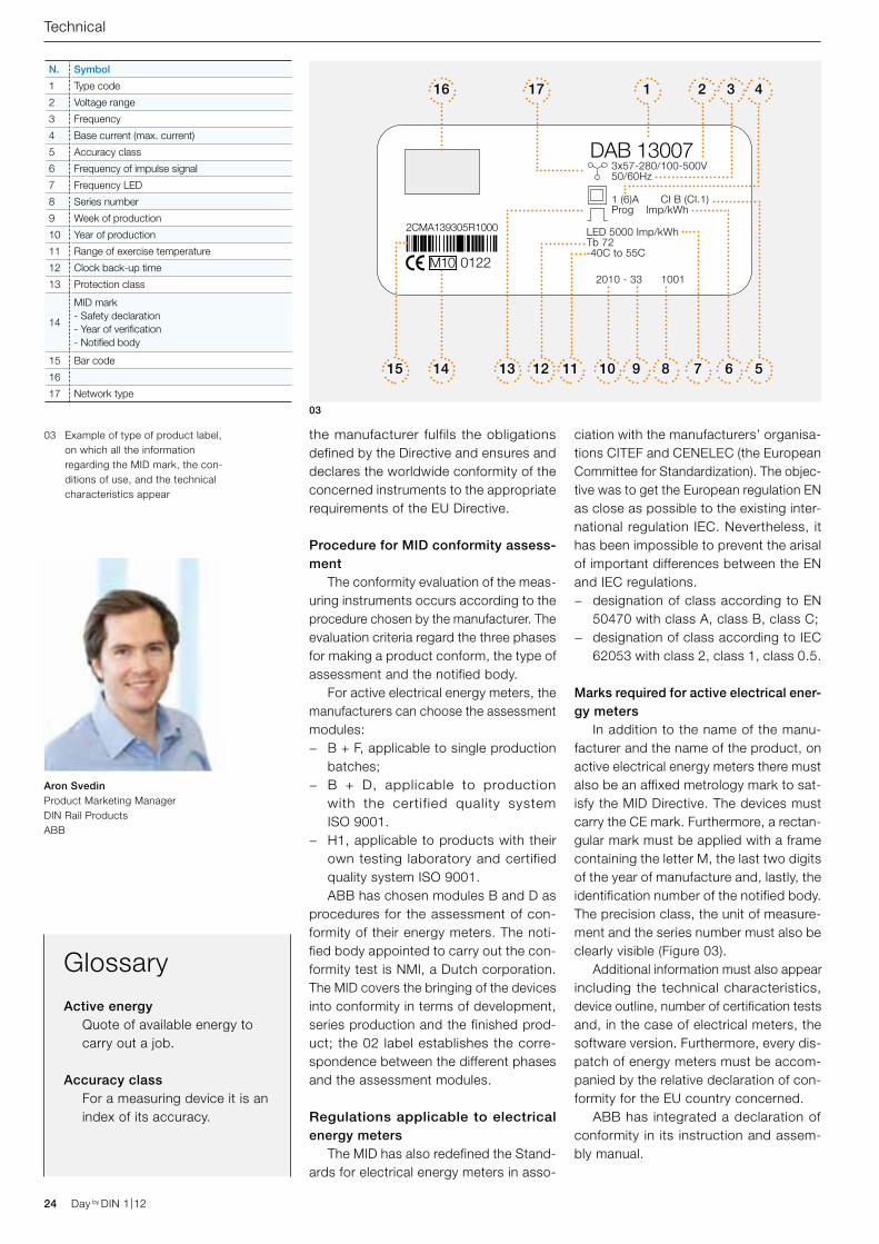
N. Symbol
1 Type code
2 Voltage range
3 Frequency
4 Base current (max. current)
5 Accuracy class
6 Frequency of impulse signal
7 Frequency LED
8 Series number
9 Week of production
10 Year of production
11 Range of exercise temperature
12 Clock back-up time
13 Protection class
14
MID mark- Safety declaration - Year of verification- Notified body
15 Bar code
16
17 Network type
24 Day by DIN 1|12
the manufacturer fulfils the obligations defined by the Directive and ensures and declares the worldwide conformity of the concerned instruments to the appropriate requirements of the EU Directive.
Procedure for MID conformity assess-ment The conformity evaluation of the meas-uring instruments occurs according to the procedure chosen by the manufacturer. The evaluation criteria regard the three phases for making a product conform, the type of assessment and the notified body. For active electrical energy meters, the manufacturers can choose the assessment modules:
− B + F, applicable to single production batches;
− B + D, applicable to production with the certified quality system ISO 9001.
− H1, applicable to products with their own testing laboratory and certified quality system ISO 9001.
ABB has chosen modules B and D as procedures for the assessment of con-formity of their energy meters. The noti-fied body appointed to carry out the con-formity test is NMI, a Dutch corporation. The MID covers the bringing of the devices into conformity in terms of development, series production and the finished prod-uct; the 02 label establishes the corre-spondence between the different phases and the assessment modules.
Regulations applicable to electrical energy meters The MID has also redefined the Stand-ards for electrical energy meters in asso-
ciation with the manufacturers’ organisa-tions CITEF and CENELEC (the European Committee for Standardization). The objec-tive was to get the European regulation EN as close as possible to the existing inter-national regulation IEC. Nevertheless, it has been impossible to prevent the arisal of important differences between the EN and IEC regulations.
− designation of class according to EN 50470 with class A, class B, class C;
− designation of class according to IEC 62053 with class 2, class 1, class 0.5.
Marks required for active electrical ener-gy meters In addition to the name of the manu-facturer and the name of the product, on active electrical energy meters there must also be an affixed metrology mark to sat-isfy the MID Directive. The devices must carry the CE mark. Furthermore, a rectan-gular mark must be applied with a frame containing the letter M, the last two digits of the year of manufacture and, lastly, the identification number of the notified body. The precision class, the unit of measure-ment and the series number must also be clearly visible (Figure 03). Additional information must also appear including the technical characteristics, device outline, number of certification tests and, in the case of electrical meters, the software version. Furthermore, every dis-patch of energy meters must be accom-panied by the relative declaration of con-formity for the EU country concerned. ABB has integrated a declaration of conformity in its instruction and assem-bly manual.
03
GlossaryActive energy
Quote of available energy to carry out a job.
Accuracy classFor a measuring device it is an index of its accuracy.
03 Example of type of product label, on which all the information regarding the MID mark, the con-ditions of use, and the technical characteristics appear
Technical
Aron SvedinProduct Marketing Manager DIN Rail ProductsABB
Day by DIN 1|12
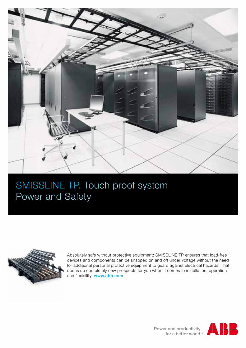
Absolutely safe without protective equipment: SMISSLINE TP ensures that load-free devices and components can be snapped on and off under voltage without the need for additional personal protective equipment to guard against electrical hazards. That opens up completely new prospects for you when it comes to installation, operation and flexibility. www.abb.com
SMISSLINE TP. Touch proof system Power and Safety
26 Day by DIN 1|12 Day by DIN 1|12
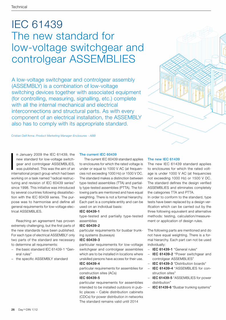
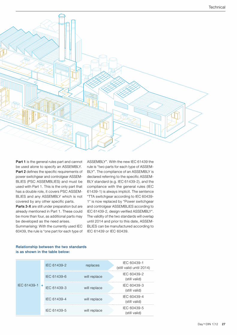
A low-voltage switchgear and controlgear assembly (ASSEMBLY) is a combination of low-voltage switching devices together with associated equipment (for controlling, measuring, signalling, etc.) complete with all the internal mechanical and electrical interconnections and structural parts. As with every component of an electrical installation, the ASSEMBLY also has to comply with its appropriate standard.
IEC 61439 The new standard for low-voltage switchgear and controlgear ASSEMBLIES
Cristian Dell’Anna: Product Marketing Manager Enclosures - ABB
Technical
In January 2009 the IEC 61439, the new standard for low-voltage switch-gear and controlgear ASSEMBLIES, was published. This was the aim of an
international project group which had been working on a task named ”radical restruc-turing and revision of IEC 60439 series” since 1998. This initiative was introduced by several countries following dissatisfac-tion with the IEC 60439 series. The pur-pose was to harmonise and define all general requirements for low-voltage elec-trical ASSEMBLIES.
Reaching an agreement has proven extremely challenging, but the first parts of the new standards have been published. For each type of electrical ASSEMBLY only two parts of the standard are necessary to determine all requirements:
− the basic standard IEC 61439-1 “Gen-eral rules”
− the specific ASSEMBLY standard
The current IEC 60439 The current IEC 60439 standard applies to enclosures for which the rated voltage is under or equal to 1000 V AC (at frequen-cies not exceeding 1000 Hz) or 1500 V DC. The standard makes a distinction between type-tested assemblies (TTA) and partial-ly type-tested assemblies (PTTA). The fol-lowing parts are mentioned and have equal weighting. There is not a formal hierarchy. Each part is a complete entity and can be used on an individual basis:IEC 60439-1 type-tested and partially type-tested assembliesIEC 60439-2 particular requirements for busbar trunk-ing systems (busways)IEC 60439-3 particular requirements for low-voltage switchgear and controlgear assemblies which are to be installed in locations where unskilled persons have access for their use. IEC 60439-4 particular requirements for assemblies for construction sites (ACs)IEC 60439-5 particular requirements for assemblies intended to be installed outdoors in pub-lic places – Cable distribution cabinets (CDCs) for power distribution in networksThe standard remains valid until 2014
The new IEC 61439The new IEC 61439 standard applies to enclosures for which the rated volt-age is under 1000 V AC (at frequencies not exceeding 1000 Hz) or 1500 V DC. The standard defines the design verified ASSEMBLIES and eliminates completely the categories TTA and PTTA. In order to conform to the standard, type tests have been replaced by a design ver-ification which can be carried out by the three following equivalent and alternative methods: testing, calculation/measure-ment or application of design rules.
The following parts are mentioned and do not have equal weighting. There is a for-mal hierarchy. Each part can not be used individually:
− IEC 61439-1 “General rules“ − IEC 61439-2 “Power switchgear and
controlgear ASSEMBLIES” − IEC 61439-3 “Distribution boards“ − IEC 61439-4 “ASSEMBLIES for con-
struction sites” − IEC 61439-5 “ASSEMBLIES for power
distribution” − IEC 61439-6 “Busbar trunking systems”
Day by DIN 1|12 27Day by DIN 1|12
Technical
Part 1 is the general rules part and cannot be used alone to specify an ASSEMBLY.Part 2 defines the specific requirements of power switchgear and controlgear ASSEM-BLIES (PSC ASSEMBLIES) and must be used with Part 1. This is the only part that has a double role, it covers PSC ASSEM-BLIES and any ASSEMBLY which is not covered by any other specific parts.Parts 3-X are still under preparation but are already mentioned in Part 1. These could be more than four, as additional parts may be developed as the need arises.Summarising: With the currently used IEC 60439, the rule is “one part for each type of
ASSEMBLY”. With the new IEC 61439 the rule is “two parts for each type of ASSEM-BLY”. The compliance of an ASSEMBLY is declared referring to the specific ASSEM-BLY standard (e.g. IEC 61439-2), and the compliance with the general rules (IEC 61439-1) is always implicit. The sentence “TTA switchgear according to IEC 60439-1“ is now replaced by “Power switchgear and controlgear ASSEMBLIES according to IEC 61439-2, design verified ASSEMBLY“. The validity of the two standards will overlap until 2014 and prior to this date, ASSEM-BLIES can be manufactured according to IEC 61439 or IEC 60439.
IEC 61439-1
Relationship between the two standards is as shown in the table below:
IEC 61439-2 replacesIEC 60439-1
(still valid until 2014)
IEC 61439-6 will replaceIEC 60439-2
(still valid)
IEC 61439-3 will replaceIEC 60439-3
(still valid)
IEC 61439-4 will replaceIEC 60439-4
(still valid)
IEC 61439-5 will replaceIEC 60439-5
(still valid)
Characteristic to be verified
Verification options available
Verification
by testing
Verification
by calculation
Verification
by design rules
10.2 Strength of material and parts Yes No No
10.3 Degree of protection of
enclosures
Yes No Yes
10.4 Clearances and creepage
distances
Yes Yes Yes
10.5.2 Effective continuity between
parts and PE
Yes No No
10.5.3 Effectiveness of the
ASSEMBLY for external faults
Yes Yes Yes
10.6 Incorporating of apparatus No No Yes
10.7 Internal electrical circuits and
connections
No No Yes
10.8 Terminals for external
conductors
No No Yes
10.9.2 Power frequency withstand
voltage
Yes No No
10.9.3 Impulse withstand voltage Yes No Yes
10.10 Temperature rise limits Yes Yes Yes
10.11 Short-circuit withstand
strength
Yes Yes Yes
10.12 EMC Yes No Yes
10.13 Mechanical operation Yes No No
28 Day by DIN 1|12 Day by DIN 1|12
Technical
Main changes – More than a single dig-it change… The new IEC 61439 includes the fol-lowing significant technical changes with respect to the last edition of IEC 60439.
Responsibility split: New terms have been introduced and there is a split in product responsibility between the “Original manufacturer” (e.g. ABB, responsible for carrying out the orig-inal design and the associated verification of an ASSEMBLY) and the “ASSEMBLY manufacturer” (e.g panel builder using an ASSEMBLY system from an Original Man-ufacturer) assuming responsibility for the completed ASSEMBLY. The Assembly Manufacturer may be a different organisation to the Original Man-ufacturer. Where the ASSEMBLY Manufac-turer introduces changes to the ASSEM-BLY configuration tested by the Original Manufacturer, he is deemed to be the Original Manufacturer in respect of these changes and has to carry out the design verification.
Design verification replaces TTA and PTTA categories:Design verification replaces type tests so the discrimination between type-tested assemblies (TTA) and partially type-tested assemblies (PTTA) is eliminated.
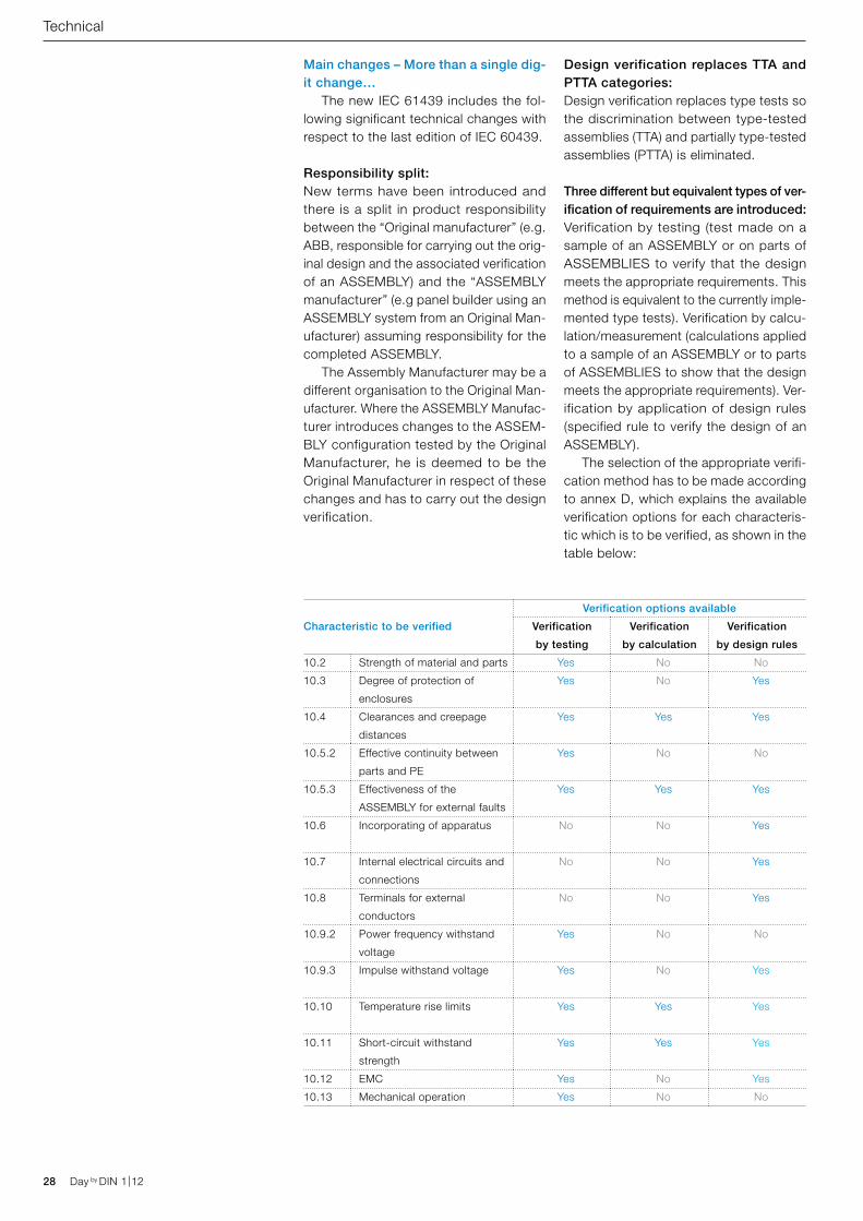
Three different but equivalent types of ver-ification of requirements are introduced: Verification by testing (test made on a sample of an ASSEMBLY or on parts of ASSEMBLIES to verify that the design meets the appropriate requirements. This method is equivalent to the currently imple-mented type tests). Verification by calcu-lation/measurement (calculations applied to a sample of an ASSEMBLY or to parts of ASSEMBLIES to show that the design meets the appropriate requirements). Ver-ification by application of design rules (specified rule to verify the design of an ASSEMBLY). The selection of the appropriate verifi-cation method has to be made according to annex D, which explains the available verification options for each characteris-tic which is to be verified, as shown in the table below:
syst
em m
anu
fact
ure
r
man
ufa
ctu
rer
of
the
AS
SE
MB
LY
ASSEMBLY
low-voltage switchgear and controlgear ASSEMBLIES
type tests for verification of conformity
TTA
type-tested
ASSEMBLIES
type-tested
units
not type-tested
units
PTTA
partial type-tested
ASSEMBLIES
routine test
completed ASSEMBLY
IEC 60439
ori
gin
al m
anu
fact
ure
r
AS
SE
MB
LY m
anu
fact
ure
ro
rig
inal
man
ufa
ctu
rer
ASSEMBLY
low-voltage switchgear and controlgear ASSEMBLIES
testing calculation
ASSEMBLY system
application of
design rules
routine verification
The ASSEMBLY manufacturer can decide:
– to manufacture the ASSEMBLY according to the
guidelines of the original manufacturer
– to deviate from the guidelines of the original
manufacturer. Where the ASSEMBLY manufacturer
incorporates his own arrangements not included in
the original manufacturer’s verification, the ASSEMBLY
manufacturer is deemed to be the original manufacturer
in respect of these arrangements.
completed ASSEMBLY
IEC 61439
design verification
carried out by the original manufacturer
Day by DIN 1|12 29Day by DIN 1|12
Technical
Additional verification:New requirements from the standard IEC 62208 (Empty enclosures for ASSEM-BLIES) have been added:
− verification of resistance to UV radiation for outdoor plastic enclosures
− verification of corrosion resistance − mandatory declaration and confirmation
of an impulse rating − lifting, mechanical impact and marking
Other changes:Temperature rise:Temperature rise requirements have been explained more clearly and have been adapted to the state of the art. One of the following methods is allowed for verification:
− testing with current − derivation (from a tested design) of
ratings for similar variants − calculation
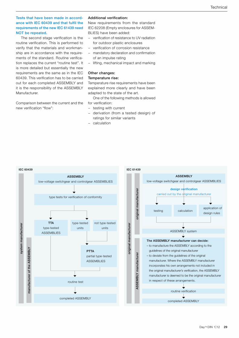
Tests that have been made in accord-ance with IEC 60439 and that fulfil the requirements of the new IEC 61439 need NOT be repeated. The second stage verification is the routine verification. This is performed to verify that the materials and workman-ship are in accordance with the require-ments of the standard. Routine verifica-tion replaces the current “routine test”. It is more detailed but essentially the new requirements are the same as in the IEC 60439. This verification has to be carried out for each completed ASSEMBLY and it is the responsibility of the ASSEMBLY Manufacturer.
Comparison between the current and the new verification “flow”:
Summary table with the main changes
IEC 60439 IEC 61439
IEC 60439-1
Type-tested and partially type-tested assemblies
IEC 61439-2
Design verified ASSEMBLIES
Mix of different rules and demands in each part Clear structure:
IEC 61439-1 “General rules“
IEC 61439-2 … -6 “Subsidiary parts” (product standard)
Each part is a complete entity and can be used on an individual basis Each “subsidiary part” is based on the “general rules” (Part 1)
and includes only the specific additional rules for the specific product
Testing each type of ASSEMBLY:
Partially type-tested or type-tested
Three alternative methods for verification:
Test, calculation/measurement, design rules
Annex E:
Agreements between Customer and Manufacturer
Annex C:
Agreements between Customer and Manufacturer are
more detailed and extended
Shared responsibility:
Original Manufacturer vs. ASSEMBLY Manufacturer
Technical changes and clarifications:
Diversity factor, verification of temperature rise,
mechanical characteristics, neutral conductor 50%,
additional verification (from IEC 62208)
30 Day by DIN 1|12
RDF The rated diversity factor is covered in more detail. In practice it is assumed that multiple functional units are not ful-ly loaded simultaneously.
Labels Labels have to be subjected to testing to verify their legibility. The following infor-mation is required on the label:
− ASSEMBLY Manufacturer‘s name − Identification number − Date of manufacture (NEW!) − IEC 61439-X (the specific part “X” has
to be specified) (NEW!)
“Grey” areas A number of “grey” areas have been clarified:
− neutral conductors will have a current rating equal to 50% of the correspond-ing phases if not otherwise specified
− agreements between Customer and Manufacturer have been more detailed, extended and listed in annex C
− it is mandatory to specify the rated current of the ASSEMBLY
− a technical report IEC 61439-0 “Guide for specifying ASSEMBLIES” is under development for a better understanding of the new standard
− questions regarding the internal form of separation have been clarified (e.g. a moulded case circuit breaker’s casing provides separation from other functional units)
Cristian Dell’AnnaProduct Marketing Manager EnclosuresABB
Technical
Day by DIN 1|12
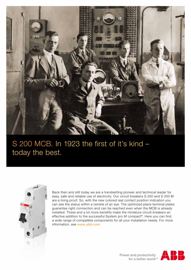
Back then and still today we are a trendsetting pioneer and technical leader for easy, safe and reliable use of electricity. Our circuit breakers S 200 and S 200 M are a living proof. So, with the new colored real contact position indication you can see the status within a twinkle of an eye. The optimized plane terminal plates guarantee right connection and can be reached even when the MCB is already installed. These and a lot more benefits make the miniature circuit breakers an effective addition to the successful System pro M compact®. Here you can find a wide range of compatible components for all your installation needs. For more information, see www.abb.com
S 200 MCB. In 1923 the first of it’s kind – today the best.
AZ_new_MCB_A4_v4.indd 1 24.01.12 15:29
32 Day by DIN 1|12
The expert answers
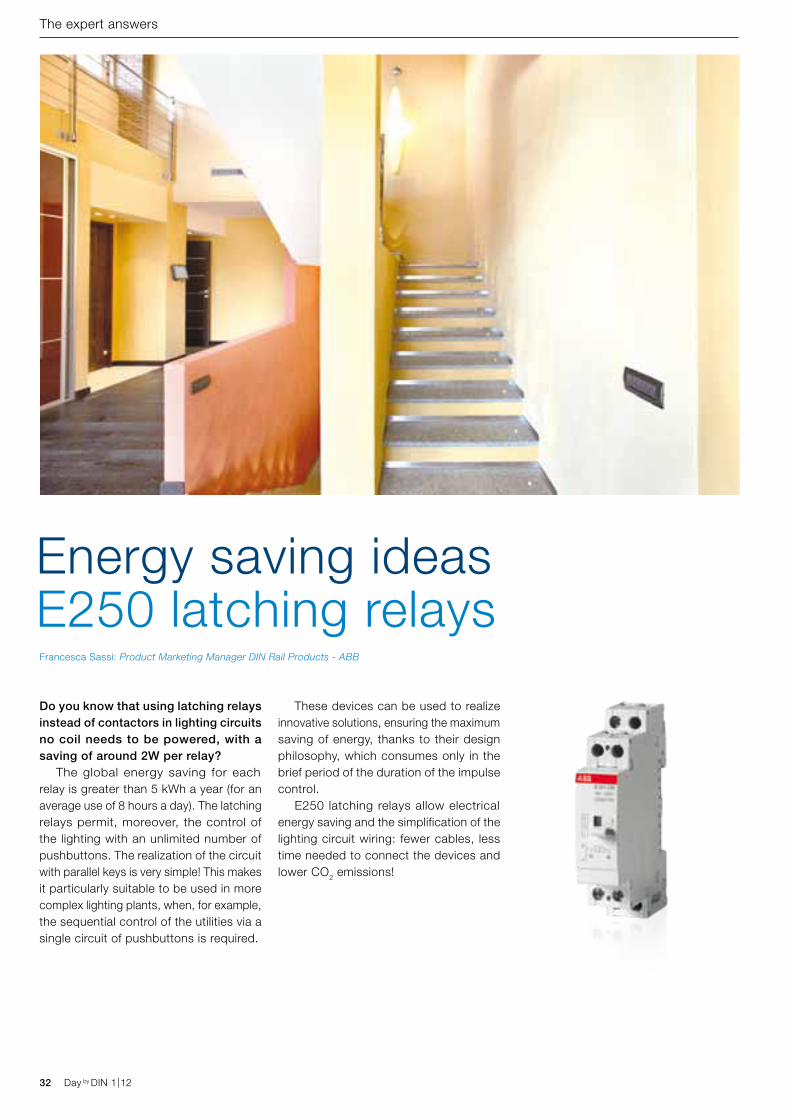
Do you know that using latching relays instead of contactors in lighting circuits no coil needs to be powered, with a saving of around 2W per relay? The global energy saving for each relay is greater than 5 kWh a year (for an average use of 8 hours a day). The latching relays permit, moreover, the control of the lighting with an unlimited number of pushbuttons. The realization of the circuit with parallel keys is very simple! This makes it particularly suitable to be used in more complex lighting plants, when, for example, the sequential control of the utilities via a single circuit of pushbuttons is required.
These devices can be used to realize innovative solutions, ensuring the maximum saving of energy, thanks to their design philosophy, which consumes only in the brief period of the duration of the impulse control. E250 latching relays allow electrical energy saving and the simplification of the lighting circuit wiring: fewer cables, less time needed to connect the devices and lower CO2 emissions!
Energy saving ideas E250 latching relaysFrancesca Sassi: Product Marketing Manager DIN Rail Products - ABB
Day by DIN 1|12
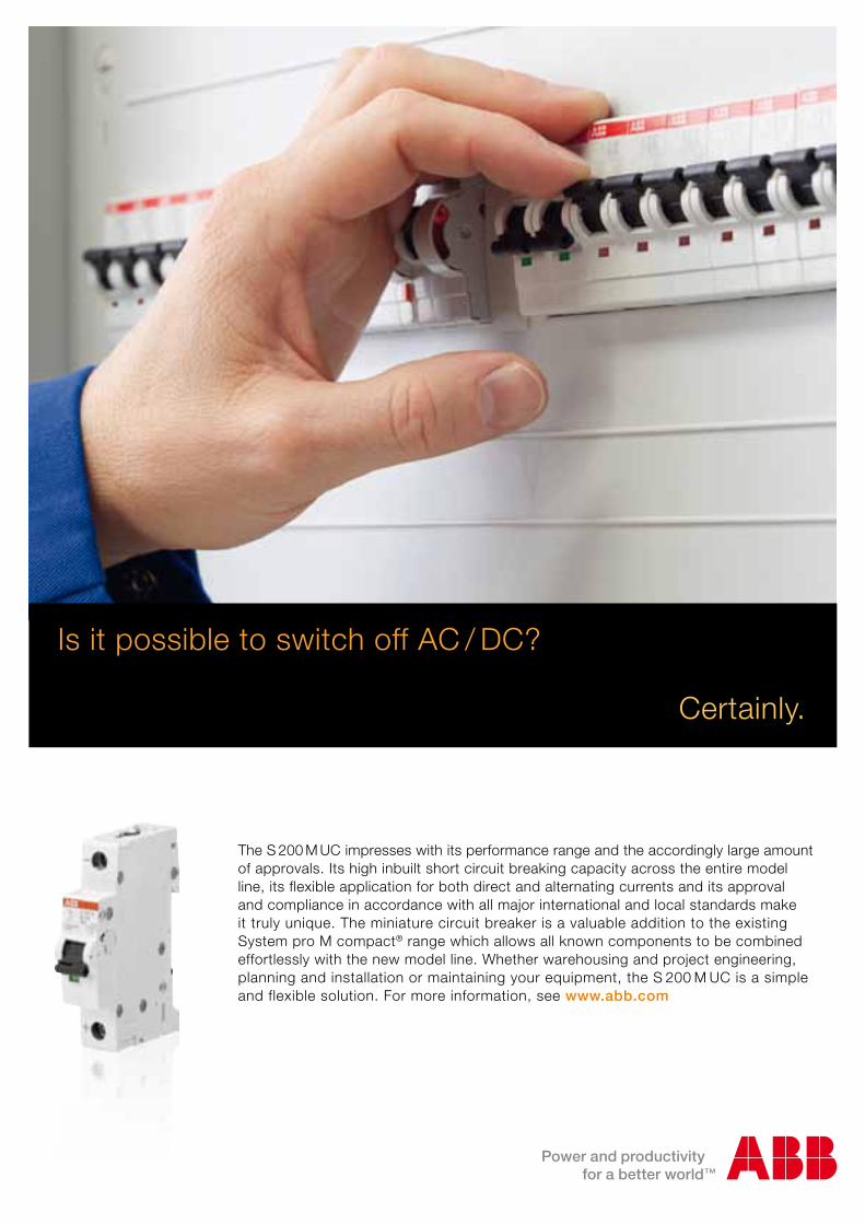
The S 200 M UC impresses with its performance range and the accordingly large amount of approvals. Its high inbuilt short circuit breaking capacity across the entire model line, its flexible application for both direct and alternating currents and its approval and compliance in accordance with all major international and local standards make it truly unique. The miniature circuit breaker is a valuable addition to the existing System pro M compact® range which allows all known components to be combined effortlessly with the new model line. Whether warehousing and project engineering, planning and installation or maintaining your equipment, the S 200 M UC is a simple and flexible solution. For more information, see www.abb.com
Is it possible to switch off AC / DC?
Certainly.
34 Day by DIN 1|12 Day by DIN 1|12
Technical
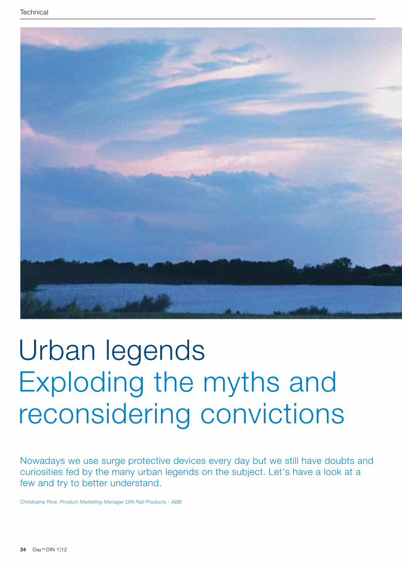
Urban legendsExploding the myths and reconsidering convictionsNowadays we use surge protective devices every day but we still have doubts and curiosities fed by the many urban legends on the subject. Let's have a look at a few and try to better understand.
Christophe Rios: Product Marketing Manager DIN Rail Products - ABB
Day by DIN 1|12 35Day by DIN 1|12
Technical
“The discharge kiloamps of a SPD must be coordinated with the short circuit current of the panel” This belief is due to a misunderstanding. The short circuit current of a panel and the discharge current of an SPD are both measured in kiloamps. However, a short circuit current normally has a sine-wave shape with a frequency of 50 Hz whilst the discharge current of a SPD has the form of a very brief impulse of just a few microseconds. Consequently, even the energy content (I2t) of a short circuit and of a discharge are very different. Once the misunderstanding has been cleared up it is evident that there is no relationship between the Isc of a switchboard and the discharge current of a SPD.
So, how do you choose the discharge current or impulse of a SPD? It is easier than it seems:
− for Type 1 there is nothing to choose, the value is set by Standard IEC 62305: nearly all SPDs have a value of 25 kA per pole and are equipped, therefore, for the worst case foreseen by the Standards in force;
− for Type 2, the nominal discharge current (In) value foreseen by the standard IEC 62305 is 5 kA;, therefore, a Type 2 SPD must have at least 5 kA of In.
For practical reasons it is nearly always advisable to choose an SPD with at least 20 kA of In to guarantee an adequate length of working life.
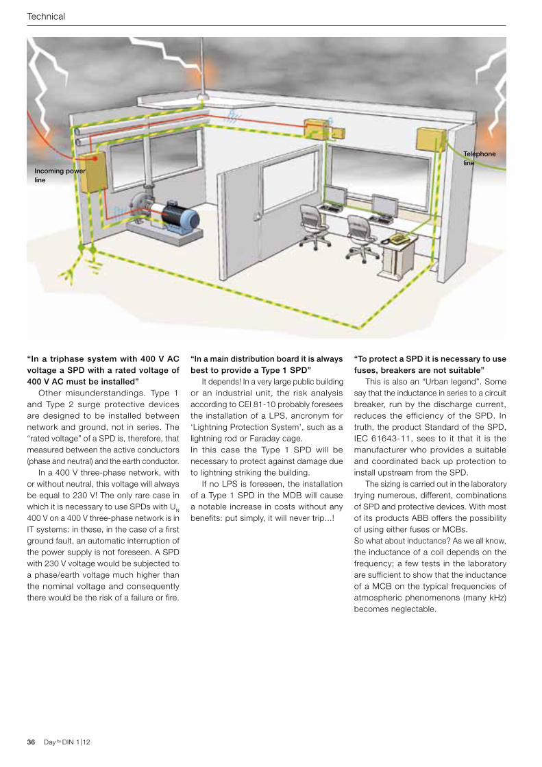
Incoming power line
Telephone line
36 Day by DIN 1|12 Day by DIN 1|12
“In a triphase system with 400 V AC voltage a SPD with a rated voltage of 400 V AC must be installed” Other misunderstandings. Type 1 and Type 2 surge protective devices are designed to be installed between network and ground, not in series. The “rated voltage” of a SPD is, therefore, that measured between the active conductors (phase and neutral) and the earth conductor. In a 400 V three-phase network, with or without neutral, this voltage will always be equal to 230 V! The only rare case in which it is necessary to use SPDs with UN
400 V on a 400 V three-phase network is in IT systems: in these, in the case of a first ground fault, an automatic interruption of the power supply is not foreseen. A SPD with 230 V voltage would be subjected to a phase/earth voltage much higher than the nominal voltage and consequently there would be the risk of a failure or fire.
“In a main distribution board it is always best to provide a Type 1 SPD” It depends! In a very large public building or an industrial unit, the risk analysis according to CEI 81-10 probably foresees the installation of a LPS, ancronym for ‘Lightning Protection System’, such as a lightning rod or Faraday cage.In this case the Type 1 SPD will be necessary to protect against damage due to lightning striking the building. If no LPS is foreseen, the installation of a Type 1 SPD in the MDB will cause a notable increase in costs without any benefits: put simply, it will never trip...!
Technical
“To protect a SPD it is necessary to use fuses, breakers are not suitable” This is also an “Urban legend”. Some say that the inductance in series to a circuit breaker, run by the discharge current, reduces the efficiency of the SPD. In truth, the product Standard of the SPD, IEC 61643-11, sees to it that it is the manufacturer who provides a suitable and coordinated back up protection to install upstream from the SPD. The sizing is carried out in the laboratory trying numerous, different, combinations of SPD and protective devices. With most of its products ABB offers the possibility of using either fuses or MCBs.So what about inductance? As we all know, the inductance of a coil depends on the frequency; a few tests in the laboratory are sufficient to show that the inductance of a MCB on the typical frequencies of atmospheric phenomenons (many kHz) becomes neglectable.
Christophe RiosProduct Marketing Manager DIN Rail ProductsABB
Day by DIN 1|12 37Day by DIN 1|12
“When lightning strikes and the SPD trips, the SPD must always be replaced” No, the SPDs are not “disposable”! Also because, if this were so, since there can be numerous atmospheric discharges during a thunderstorm, the SPD would be totally ineffective. In reality, SPDs are designed and tested in order to trip and to return as good as new at least 15 times, if subjected to their rated discharge current. Given that statistically speaking the discharge current induced by the atmospheric phenomenon is inferior to the rated current, the SPD can trip even hundreds of times before reaching the so-called “end of life”. This is the reason why SPDs are installed every day, but changing a cartridge at the end of its life is a rare occurence.
“A Type 2 SPD is nothing more than a varistor…” The varistor is a fundamental component of all Type 2 SPDs, but we must not forget that varistors have two characteristics which a SPD must remedy: they end their operative life in short circuit and they conduct a small permanent current. In order to prevent the short circuit effects on the life of the varistor, a small, essential element is provided inside a SPD: a thermal disconnector which isolates the varistor from the network in case of overheating, ensuring a safe end of life for the SPD. Instead, in order to prevent the permanent earth current, which could involve the risk of indirect contacts, in some Type 2 SPDs the N-PE module, which is designed to lead the discharge current towards the earth conductor, is not realized with a varistor, but with a voltage switching type element (for example, a spark gap), able to permanently prevent the current flow towards the PE. All ABB OVR T2 1N and 3N SPDs are realized with this technology.
“The remote signalling contact tells me the SPD has intervened” No, the signalling contact switches only when the SPD has reached the end of its operative life. Very useful in the event of unprotected distribution boards, the information can be used, for example, in order to suddenly replace the cartridge in end of life and to restore the protection from the overvoltages.
“A SPD for alternative current can also be used in direct current; it is just a matter of multiplying its rated voltage by the root of two” This is the principle for which many SPD for alternative current at 400 V have without warning become SPDs for photovoltaic at 600 V DC. The ABB position has always been very clear on this point: the varistors sooner or later go into short circuit and interrupting a short circuit in direct current is much more difficult than in current. It cannot, therefore, be absolutely guaranteed that the thermal disconnector integrated in a SPD designed for alternative current is able to guarantee the disconnection when the same SPD is installed in a photovoltaic system. According to UTE C 61 740-51, the manufacturer shall test the products under DC condition and shall declare specific DC characteristics of the SPD.
Technical
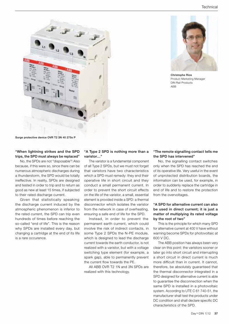
Surge protective device OVR T2 3N 40 275s P
200
100
0
-100
-200
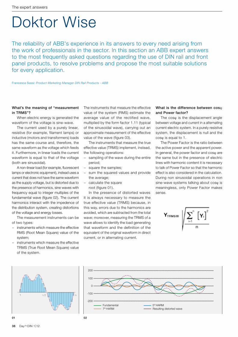
Fundamental7th HARM
5th HARMResulting distorted wave
38 Day by DIN 1|12 Day by DIN 1|12
The expert answers
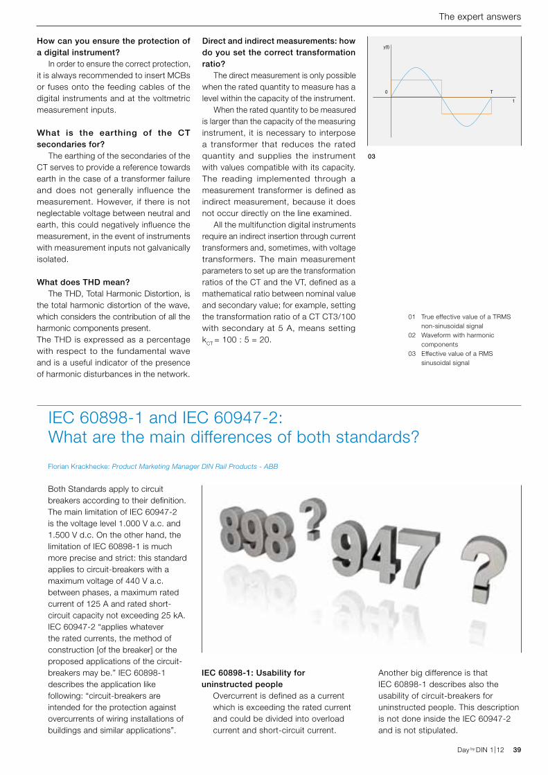
What’s the meaning of “measurement in TRMS”? When electric energy is generated the waveform of the voltage is sine-wave. The current used by a purely linear, resistive (for example, filament lamps) or inductive (motors and transformers) loads has the same course and, therefore, the same waveform as the voltage which feeds it. Furthermore, in linear loads the current waveform is equal to that of the voltage (both are sinusoidal). A non-linear load (for example, fluorescent lamps or electronic equipment), instead uses a current that does not have the same waveform as the supply voltage, but is distorted due to the presence of harmonics, sine waves with frequency equal to integer multiples of the fundamental wave (figure 02). The current harmonics interact with the impedence of the distribution system, creating distortions of the voltage and energy losses. The measurement instruments can be of two types:
− instruments which measure the effective RMS (Root Mean Square) value of the system;
− instruments which measure the effective TRMS (True Root Mean Square) value of the system.
The instruments that measure the effective value of the system (RMS) estimate the average value of the rectified wave, multiplied by the form factor 1.11 (typical of the sinusoidal wave), carrying out an approximate measurement of the effective value of the wave (figure 03). The instruments that measure the true effective value (TRMS) implement, instead, the following operations:
− sampling of the wave during the entire period;
− square the samples; − sum the squared values and provide
the average; − calculate the square
root (figure 01). In the presence of distorted waves it is always necessary to measure the true effective value (TRMS) because, in this way, errors due to the harmonics are avoided, which are subtracted from the total wave; moreover, measuring the TRMS of a wave allows to identify the load generating that waveform and the definition of the equivalent of the original waveform in direct current, or in alternating current.
Doktor WiseThe reliability of ABB's experience in its answers to every need arising from the work of professionals in the sector. In this section an ABB expert answers to the most frequently asked questions regarding the use of DIN rail and front panel products, to resolve problems and propose the most suitable solutions for every application.
What is the difference between cosj and Power factor? The cosj is the displacement angle between voltage and current in a alternating current electric system. In a purely resistive system, the displacement is null and the cosj is equal to 1. The Power Factor is the ratio between the active power and the apparent power. In general, the power factor and cosj are the same but in the presence of electric lines with harmonic content it is necessary to talk of Power Factor so that the harmonic effect is also considered in the calculation. During non sinusoidal operations in non sine-wave systems talking about cosj is meaningless, only Power Factor makes sense.
01 02
Francesca Sassi: Product Marketing Manager DIN Rail Products - ABB
y(t)
0 T
t
Day by DIN 1|12 39Day by DIN 1|12
The expert answers
How can you ensure the protection of a digital instrument? In order to ensure the correct protection, it is always recommended to insert MCBs or fuses onto the feeding cables of the digital instruments and at the voltmetric measurement inputs.
What is the earthing of the CT secondaries for? The earthing of the secondaries of the CT serves to provide a reference towards earth in the case of a transformer failure and does not generally influence the measurement. However, if there is not neglectable voltage between neutral and earth, this could negatively influence the measurement, in the event of instruments with measurement inputs not galvanically isolated.
What does THD mean? The THD, Total Harmonic Distortion, is the total harmonic distortion of the wave, which considers the contribution of all the harmonic components present. The THD is expressed as a percentage with respect to the fundamental wave and is a useful indicator of the presence of harmonic disturbances in the network.
Direct and indirect measurements: how do you set the correct transformation ratio? The direct measurement is only possible when the rated quantity to measure has a level within the capacity of the instrument. When the rated quantity to be measured is larger than the capacity of the measuring instrument, it is necessary to interpose a transformer that reduces the rated quantity and supplies the instrument with values compatible with its capacity. The reading implemented through a measurement transformer is defined as indirect measurement, because it does not occur directly on the line examined. All the multifunction digital instruments require an indirect insertion through current transformers and, sometimes, with voltage transformers. The main measurement parameters to set up are the transformation ratios of the CT and the VT, defined as a mathematical ratio between nominal value and secondary value; for example, setting the transformation ratio of a CT CT3/100 with secondary at 5 A, means setting kCT = 100 : 5 = 20.
03
01 True effective value of a TRMS non-sinusoidal signal
02 Waveform with harmonic components
03 Effective value of a RMS sinusoidal signal
Florian Krackhecke: Product Marketing Manager DIN Rail Products - ABB
Both Standards apply to circuit breakers according to their definition. The main limitation of IEC 60947-2 is the voltage level 1.000 V a.c. and 1.500 V d.c. On the other hand, the limitation of IEC 60898-1 is much more precise and strict: this standard applies to circuit-breakers with a maximum voltage of 440 V a.c. between phases, a maximum rated current of 125 A and rated short-circuit capacity not exceeding 25 kA.IEC 60947-2 “applies whatever the rated currents, the method of construction [of the breaker] or the proposed applications of the circuit-breakers may be.” IEC 60898-1 describes the application like following: “circuit-breakers are intended for the protection against overcurrents of wiring installations of buildings and similar applications”.
IEC 60898-1 and IEC 60947-2: What are the main differences of both standards?
IEC 60898-1: Usability for uninstructed people
Overcurrent is defined as a current which is exceeding the rated current and could be divided into overload current and short-circuit current.
Another big difference is that IEC 60898-1 describes also the usability of circuit-breakers for uninstructed people. This description is not done inside the IEC 60947-2 and is not stipulated.
40 Day by DIN 1|12 Day by DIN 1|12
Case History
Day by DIN 1|12 41Day by DIN 1|12
Case History
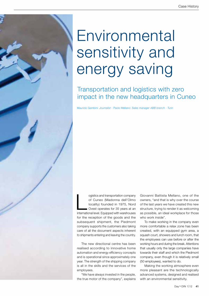
Transportation and logistics with zero impact in the new headquarters in Cuneo
Logistics and transportation company of Cuneo (Madonna dell’Olmo locality) founded in 1975, Nord Ovest operates for 35 years at an
international level. Equipped with warehouses for the reception of the goods and the subsequent shipment, the Piedmont company supports the customers also taking care of all the document aspects inherent to shipments entering and leaving the country.
The new directional centre has been realised according to innovative home automation and energy efficiency concepts and is operational since approximately one year. The strength of the shipping company is all in the skills and the services of the employees.
“We have always invested in the people, the true motor of the company”, explains
Giovanni Battista Mellano, one of the owners, “and that is why over the course of the last years we have created this new structure, trying to render it as welcoming as possible, an ideal workplace for those who work inside”.
To make working in the company even more comfortable a relax zone has been created, with an equipped gym area, a squash court, showers and lunch room, that the employees can use before or after the working hours and during the break. Attentions that usually only the large companies have towards their staff and which the Piedmont company, even though it is relatively small (50 employees), wanted to do.
Making the working atmosphere even more pleasant are the technologically advanced systems, designed and realised with an environmental sensitivity.
Environmental sensitivity and energy saving
Maurizio Gambini: Journalist - Paolo Mellano: Sales manager ABB branch - Turin
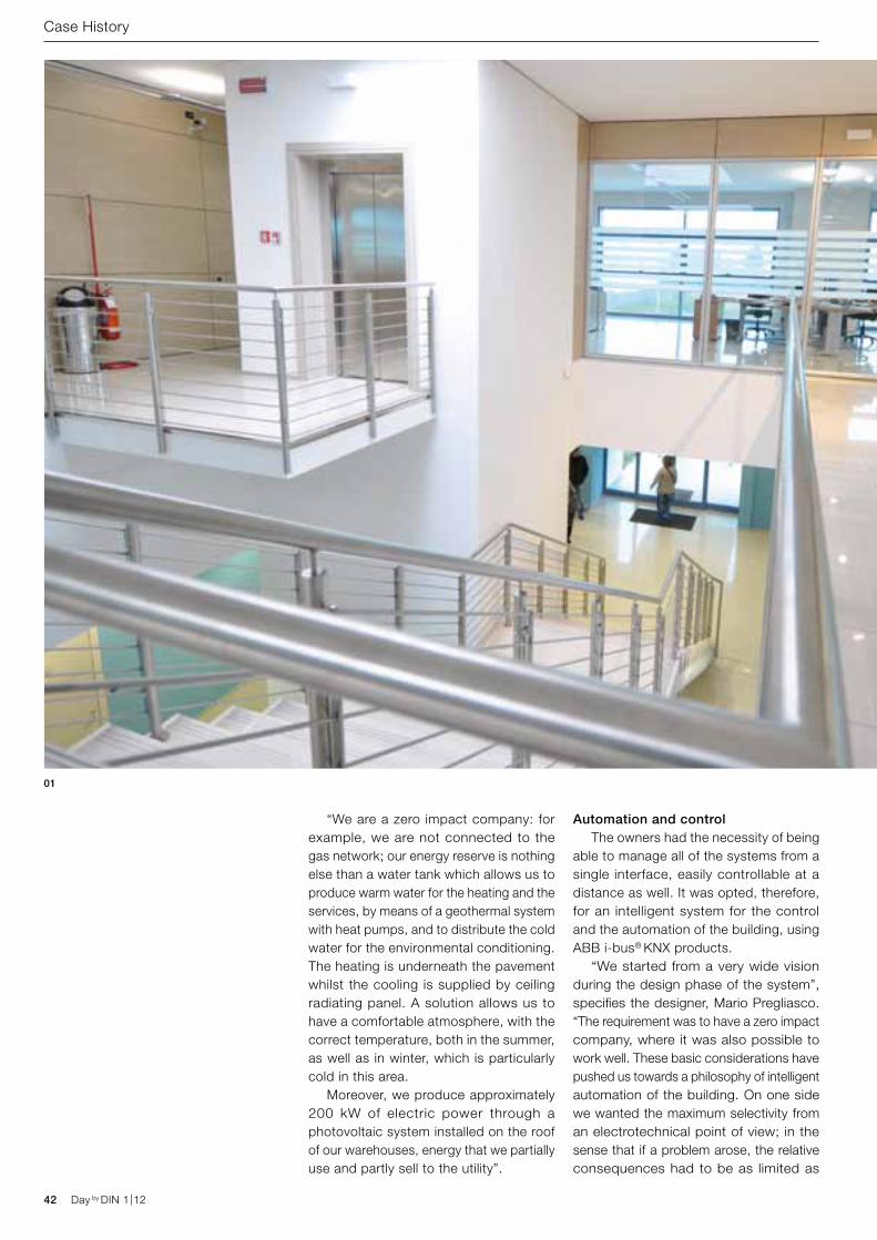
42 Day by DIN 1|12 Day by DIN 1|12
Case History
“We are a zero impact company: for example, we are not connected to the gas network; our energy reserve is nothing else than a water tank which allows us to produce warm water for the heating and the services, by means of a geothermal system with heat pumps, and to distribute the cold water for the environmental conditioning. The heating is underneath the pavement whilst the cooling is supplied by ceiling radiating panel. A solution allows us to have a comfortable atmosphere, with the correct temperature, both in the summer, as well as in winter, which is particularly cold in this area.
Moreover, we produce approximately 200 kW of electric power through a photovoltaic system installed on the roof of our warehouses, energy that we partially use and partly sell to the utility”.
Automation and controlThe owners had the necessity of being
able to manage all of the systems from a single interface, easily controllable at a distance as well. It was opted, therefore, for an intelligent system for the control and the automation of the building, using ABB i-bus® KNX products.
“We started from a very wide vision during the design phase of the system”, specifies the designer, Mario Pregliasco. “The requirement was to have a zero impact company, where it was also possible to work well. These basic considerations have pushed us towards a philosophy of intelligent automation of the building. On one side we wanted the maximum selectivity from an electrotechnical point of view; in the sense that if a problem arose, the relative consequences had to be as limited as
01
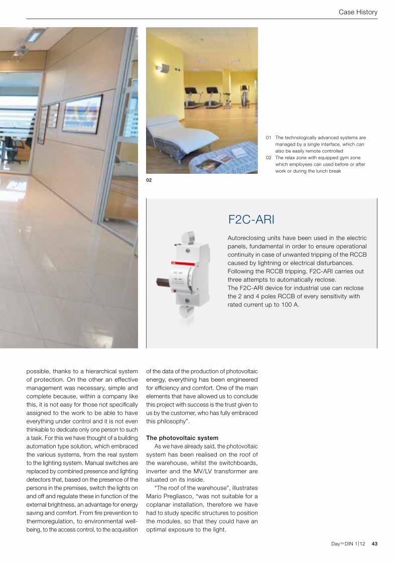
Autoreclosing units have been used in the electric panels, fundamental in order to ensure operational continuity in case of unwanted tripping of the RCCB caused by lightning or electrical disturbances.Following the RCCB tripping, F2C-ARI carries out three attempts to automatically reclose. The F2C-ARI device for industrial use can reclose the 2 and 4 poles RCCB of every sensitivity with rated current up to 100 A.
F2C-ARI
Day by DIN 1|12 43Day by DIN 1|12
Case History
possible, thanks to a hierarchical system of protection. On the other an effective management was necessary, simple and complete because, within a company like this, it is not easy for those not specifically assigned to the work to be able to have everything under control and it is not even thinkable to dedicate only one person to such a task. For this we have thought of a building automation type solution, which embraced the various systems, from the real system to the lighting system. Manual switches are replaced by combined presence and lighting detectors that, based on the presence of the persons in the premises, switch the lights on and off and regulate these in function of the external brightness, an advantage for energy saving and comfort. From fire prevention to thermoregulation, to environmental well-being, to the access control, to the acquisition
of the data of the production of photovoltaic energy, everything has been engineered for efficiency and comfort. One of the main elements that have allowed us to conclude this project with success is the trust given to us by the customer, who has fully embraced this philosophy”.
The photovoltaic systemAs we have already said, the photovoltaic
system has been realised on the roof of the warehouse, whilst the switchboards, inverter and the MV/LV transformer are situated on its inside.
“The roof of the warehouse”, illustrates Mario Pregliasco, “was not suitable for a coplanar installation, therefore we have had to study specific structures to position the modules, so that they could have an optimal exposure to the light.
02
01 The technologically advanced systems are managed by a single interface, which can also be easily remote controlled
02 The relax zone with equipped gym zone which employees can used before or after work or during the lunch break
44 Day by DIN 1|12 Day by DIN 1|12
The bidirectional connection in medium voltage at the delivery point is realised with a buried cable”.
Service redundance and continuityThe pulsing heart of a company like
Nord Ovest is the room where the server of the computer system is housed.
“A large part of the company’s work”, confirms Giovanni Battista Mellano, “is based on the data, the connections with the customers. This is the reason why we have invested a lot in hardware and software, but also on the technological systems that has to guarantee the operation under all circumstances: it would be a disaster if we were left without power».
This is the reason why the server room was constructed with particular details, in order to guarantee the operational continuity. “Even if it is very improbable, we had to consider the hypothesis that a photovoltaic module was damaged or a string broke down, at the same time as a network drop”, specifies Mario Pregliasco. “Taking advantage of the functionalities of
the building automation system, we have been able to realise a complete structure, with doubled circuits, in which the gen set, the UPS and the photovoltaic system are integrated, in order to guarantee the continuity of the electric power supply. It is within this philosophy that automatic self-reclosing switches have been used in the electric panels, fundamental in order to avoid unwanted trippings provoked by thunderstorms or electrical disturbances.
For that regarding the communications, operational continuity has guided the project. We are connected with fibre optic to a telecom central, whilst a copper line, connected to another central, always ensures the service in case the first breaks down.
In other words, we have paid the maximum attention to the redundancy of the systems, perhaps influenced by a common passion, mine and of that to the owner, for scuba diving, where nothing can be left to chance”.
Case History
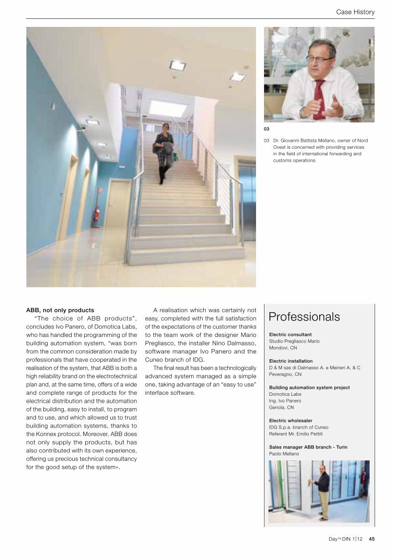
ProfessionalsElectric consultant Studio Pregliasco MarioMondovì, CN
Electric installationD & M sas di Dalmasso A. e Meineri A. & CPeveragno, CN
Building automation system projectDomotica LabsIng. Ivo PaneroGenola, CN
Electric wholesalerIDG S.p.a. branch of CuneoReferent Mr. Emilio Pettiti
Sales manager ABB branch - TurinPaolo Mellano
Day by DIN 1|12 45Day by DIN 1|12
ABB, not only products“The choice of ABB products”,
concludes Ivo Panero, of Domotica Labs, who has handled the programming of the building automation system, “was born from the common consideration made by professionals that have cooperated in the realisation of the system, that ABB is both a high reliability brand on the electrotechnical plan and, at the same time, offers of a wide and complete range of products for the electrical distribution and the automation of the building, easy to install, to program and to use, and which allowed us to trust building automation systems, thanks to the Konnex protocol. Moreover, ABB does not only supply the products, but has also contributed with its own experience, offering us precious technical consultancy for the good setup of the system».
A realisation which was certainly not easy, completed with the full satisfaction of the expectations of the customer thanks to the team work of the designer Mario Pregliasco, the installer Nino Dalmasso, software manager Ivo Panero and the Cuneo branch of IDG.
The final result has been a technologically advanced system managed as a simple one, taking advantage of an “easy to use” interface software.
Case History
03
03 Dr. Giovanni Battista Mellano, owner of Nord Ovest is concerned with providing services in the field of international forwarding and customs operations
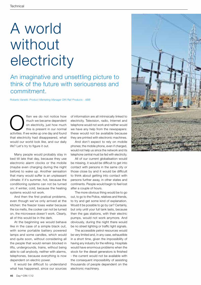
46 Day by DIN 1|12 Day by DIN 1|12
Technical
Often we do not notice how much we became dependent on electricity, just how much this is present in our normal
activities. If we woke up one day and found that electricity had disappeared, what would our world look like, and our daily life? Let's try to figure it out.
Many people would probably stay in bed till late that day, because they use electronic alarm clocks or the mobile (maybe even charging during the night before) to wake up. Another sensation that many would suffer is an unpleasant climate: if it's summer, hot, because the conditioning systems can not be turned on; if winter, cold, because the heating systems would not work.
And then the first pratical problems, even though we've only arrived at the kitchen: the freezer loses water because the ice melts, the cooker can not be turned on, the microwave doesn't work. Clearly, all of this would be in the dark.
At the beginning we would behave like in the case of a simple black out, with some portable battery powered lamps and some candles, which would end quite soon, without considering all the people that would remain blocked in lifts, undergrounds, trains, without being able to call anybody, neither with alarms, telephones, because everything is now dependent on electric power.
It would be difficult to understand what has happened, since our sources
of information are all intrinsically linked to electricity. Television, radio, Internet and telephone would not work and neither would we have any help from the newspapers: these would not be available because they are printed with electronic machines.
And don’t expect to rely on mobile phones; the mobile phone, even if charged, would not help us since the network and its telephone central must be fed with electricity.
All of our current globalisation would be missing, it would be difficult to get into contact with persons in the same city or those close by and it would be difficult to think about getting into contact with persons further away, in other states and continents. People would begin to feel lost after a couple of hours.
The more obvious thing would be to go out, to go to the Police, relatives and friends, to try and get some kind of explanation. Would it be possible to go by car? Certainly, but only until your full tank lasts, because then the gas stations, with their electric pumps, would not work anymore. And obviously, during the night there would be no street lighting or traffic light signals.
The accessible petrol resources would be very limited and, in any case, exhaustible in a short time, given the impossibility of having any industry for the refining. Hospitals would have enormous problems when the stock for the diesel generators is finished - the current would not be available with the consequent impossibility of assisting thousands of people dependent on the electronic machinery.
A world without electricityAn imaginative and unsettling picture to think of the future with seriousness and commitment.Roberto Vanetti: Product Marketing Manager DIN Rail Products - ABB
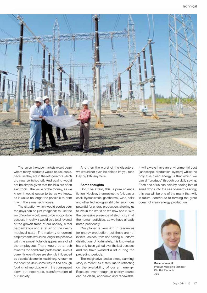
Roberto VanettiProduct Marketing Manager DIN Rail Products ABB
Day by DIN 1|12 47Day by DIN 1|12
Technical
The run on the supermarkets would begin where many products would be unusable, because they are in the refrigerators which are now switched off. And paying would not be simple given that the bills are often electronic. The value of the money, as we know it would cease to be as we know, as it would no longer be possible to print it with the same techniques.
The situation which would evolve over the days can be just imagined: to use the word 'evolve' would already be inopportune because in reality it would be a total reversal of the growth trend of our society, a real barbarization and a return to the nearly medieval state. The majority of current employments would no longer be possible with the almost total disappearance of all the employees. There would be a rush towards the handicraft professions, even if currently even those are strongly influenced by electric/electronic machinery. A return to the countryside in some way to find enough food is not improbable with the consequent slow, but inexorable, transformation of our society.
And then the worst of the disasters: we would not even be able to let you read Day by DIN anymore!
Some thoughtsDon't be afraid, this is pure science
fiction! Nuclear, thermoelectric (oil, gas or coal), hydroelectric, geothermal, wind, solar and other technologies still offer enormous potential for energy production, allowing us to live in the world as we now see it, with the pervasive presence of electricity in all the human activities, as we have already noted previously.
Our planet is very rich in resources for energy production, but these are not infinite, asides from not having a uniform distribution. Unfortunately, this knowledge has only been gained over the last decades and we have wasted a lot during the preceding periods.
The imaginative (and at times, alarming) story is meant as a stimulus to reflecting on the availability of current energy. Because, even though an energy source can be clean, economic and renewable,
it will always have an environmental cost (landscape, production, system) whilst the only true clean energy is that which we can all “produce” through our daily saving. Each one of us can help by adding lots of small drops into the sea of energy saving; this sea will be one of the many that will, in future, contribute to forming the great ocean of clean energy production.
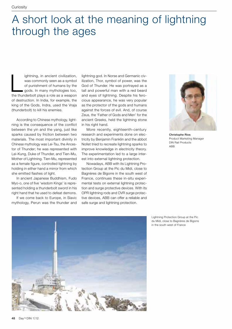
Christophe RiosProduct Marketing Manager DIN Rail ProductsABB
Lightning Protection Group at the Pic du Midi, close to Bagnères de Bigorre in the south west of France
48 Day by DIN 1|12 Day by DIN 1|12
Curiosity
A short look at the meaning of lightning through the ages
Lightning, in ancient civilization, was commonly seen as a symbol of punishment of humans by the gods. In many mythologies too,
the thunderbolt plays a role as a weapon of destruction. In India, for example, the king of the Gods, Indra, used the Vraja (thunderbolt) to kill his enemies.
According to Chinese mythology, light-ning is the consequence of the conflict between the yin and the yang, just like sparks caused by friction between two materials. The most important divinity in Chinese mythology was Lei-Tsu, the Ances-tor of Thunder; he was represented with Lei-Kung, Duke of Thunder, and Tien-Mu, Mother of Lightning. Tien-Mu, represented as a female figure, controlled lightning by holding in either hand a mirror from which she emitted flashes of light. In ancient Japanese Buddhism, Fudo Myo-o, one of five ‘wisdom Kings’ is repre-sented holding a thunderbolt sword in his right hand that he used to defeat demons. If we come back to Europe, in Slavic mythology, Perun was the thunder and
lightning god. In Norse and Germanic civ-ilization, Thor, symbol of power, was the God of Thunder. He was portrayed as a tall and powerful man with a red beard and eyes of lightning. Despite his fero-cious appearance, he was very popular as the protector of the gods and humans against the forces of evil. And, of course Zeus, the ‘Father of Gods and Men’ for the ancient Greeks, held the lightning stone in his right hand. More recently, eighteenth-century research and experiments done on elec-tricity by Benjamin Franklin and the abbot Nollet tried to recreate lightning sparks to improve knowledge in electricity theory. The experimentation led to a large inter-est into external lightning protection. Nowadays, ABB with its Lightning Pro-tection Group at the Pic du Midi, close to Bagnères de Bigorre in the south west of France, continues these in-situ experi-mental tests on external lightning protec-tion and surge protective devices. With its OPR lightning rods and OVR surge protec-tive devices, ABB can offer a reliable and safe surge and lightning protection.
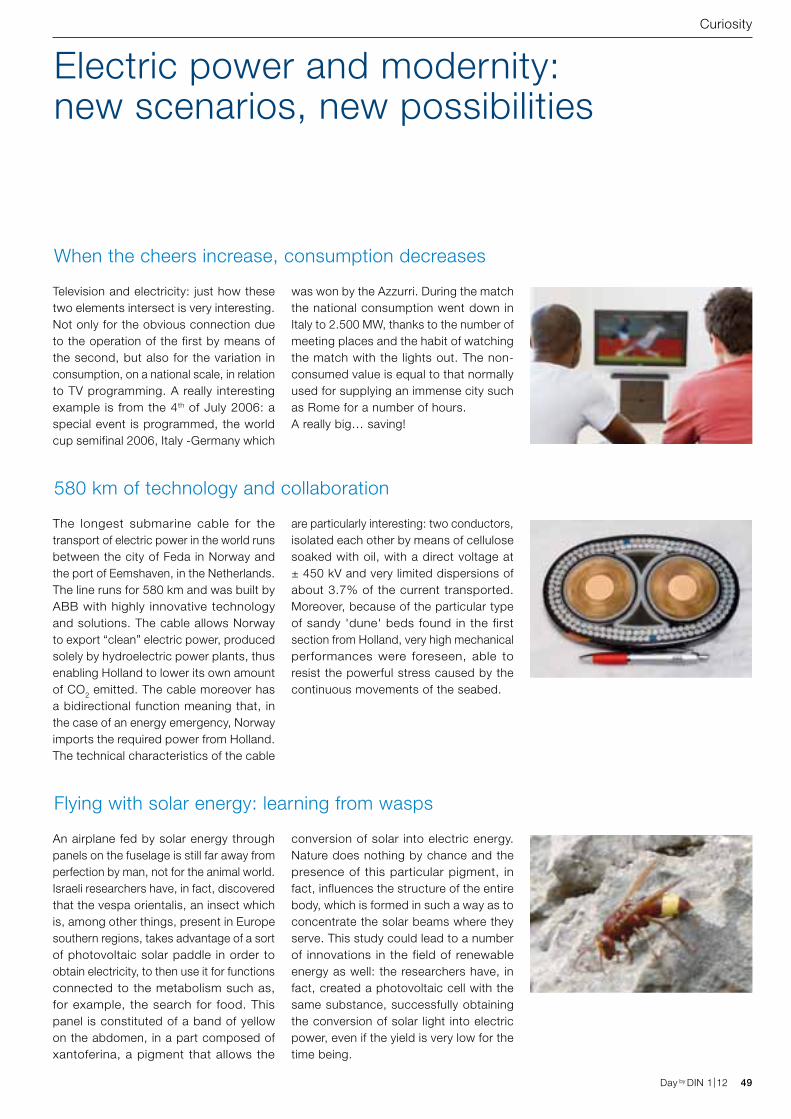
Day by DIN 1|12 49Day by DIN 1|12
Television and electricity: just how these two elements intersect is very interesting. Not only for the obvious connection due to the operation of the first by means of the second, but also for the variation in consumption, on a national scale, in relation to TV programming. A really interesting example is from the 4th of July 2006: a special event is programmed, the world cup semifinal 2006, Italy -Germany which
was won by the Azzurri. During the match the national consumption went down in Italy to 2.500 MW, thanks to the number of meeting places and the habit of watching the match with the lights out. The non-consumed value is equal to that normally used for supplying an immense city such as Rome for a number of hours. A really big… saving!
The longest submarine cable for the transport of electric power in the world runs between the city of Feda in Norway and the port of Eemshaven, in the Netherlands. The line runs for 580 km and was built by ABB with highly innovative technology and solutions. The cable allows Norway to export “clean” electric power, produced solely by hydroelectric power plants, thus enabling Holland to lower its own amount of CO2 emitted. The cable moreover has a bidirectional function meaning that, in the case of an energy emergency, Norway imports the required power from Holland. The technical characteristics of the cable
are particularly interesting: two conductors, isolated each other by means of cellulose soaked with oil, with a direct voltage at ± 450 kV and very limited dispersions of about 3.7% of the current transported. Moreover, because of the particular type of sandy 'dune' beds found in the first section from Holland, very high mechanical performances were foreseen, able to resist the powerful stress caused by the continuous movements of the seabed.
An airplane fed by solar energy through panels on the fuselage is still far away from perfection by man, not for the animal world. Israeli researchers have, in fact, discovered that the vespa orientalis, an insect which is, among other things, present in Europe southern regions, takes advantage of a sort of photovoltaic solar paddle in order to obtain electricity, to then use it for functions connected to the metabolism such as, for example, the search for food. This panel is constituted of a band of yellow on the abdomen, in a part composed of xantoferina, a pigment that allows the
conversion of solar into electric energy. Nature does nothing by chance and the presence of this particular pigment, in fact, influences the structure of the entire body, which is formed in such a way as to concentrate the solar beams where they serve. This study could lead to a number of innovations in the field of renewable energy as well: the researchers have, in fact, created a photovoltaic cell with the same substance, successfully obtaining the conversion of solar light into electric power, even if the yield is very low for the time being.
Electric power and modernity: new scenarios, new possibilities
When the cheers increase, consumption decreases
580 km of technology and collaboration
Flying with solar energy: learning from wasps
Curiosity
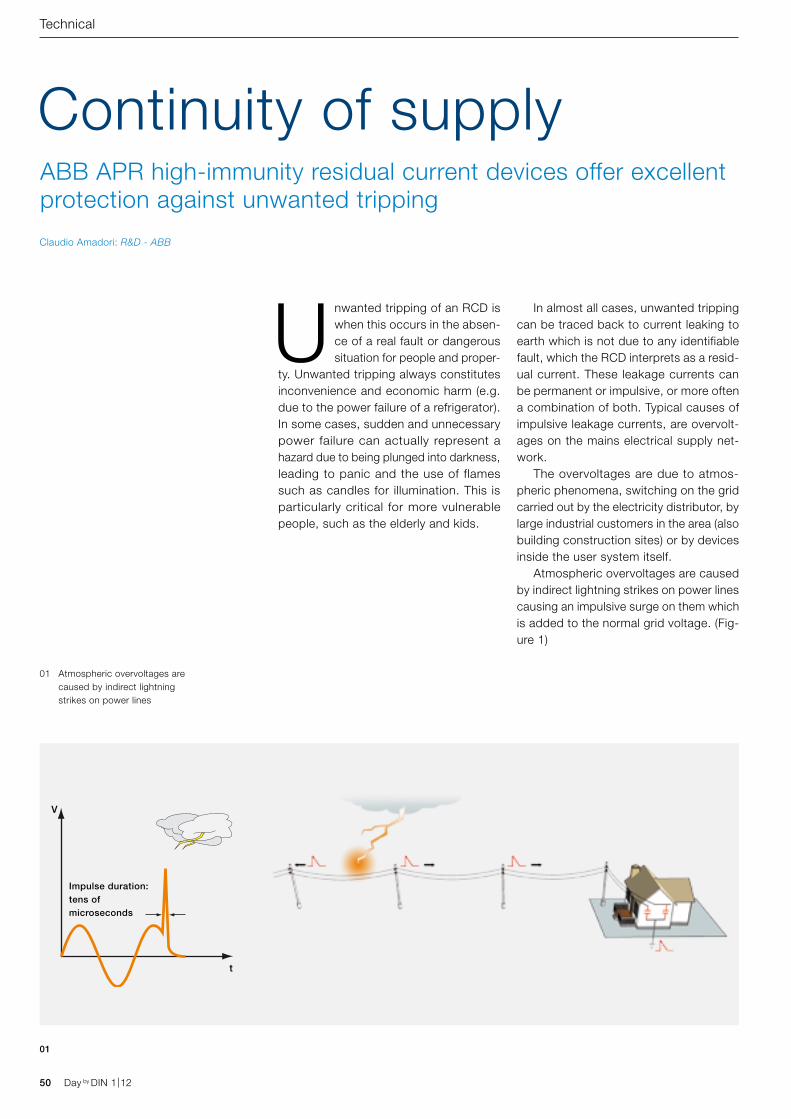
t
V
Impulse duration: tens of microseconds
50 Day by DIN 1|12 Day by DIN 1|12
Technical
Unwanted tripping of an RCD is when this occurs in the absen-ce of a real fault or dangerous situation for people and proper-
ty. Unwanted tripping always constitutes inconvenience and economic harm (e.g. due to the power failure of a refrigerator). In some cases, sudden and unnecessary power failure can actually represent a hazard due to being plunged into darkness, leading to panic and the use of flames such as candles for illumination. This is particularly critical for more vulnerable people, such as the elderly and kids.
In almost all cases, unwanted tripping can be traced back to current leaking to earth which is not due to any identifiable fault, which the RCD interprets as a resid-ual current. These leakage currents can be permanent or impulsive, or more often a combination of both. Typical causes of impulsive leakage currents, are overvolt-ages on the mains electrical supply net-work. The overvoltages are due to atmos-pheric phenomena, switching on the grid carried out by the electricity distributor, by large industrial customers in the area (also building construction sites) or by devices inside the user system itself. Atmospheric overvoltages are caused by indirect lightning strikes on power lines causing an impulsive surge on them which is added to the normal grid voltage. (Fig-ure 1)
Continuity of supplyABB APR high-immunity residual current devices offer excellent protection against unwanted tripping
Claudio Amadori: R&D - ABB
01 Atmospheric overvoltages are caused by indirect lightning strikes on power lines
01
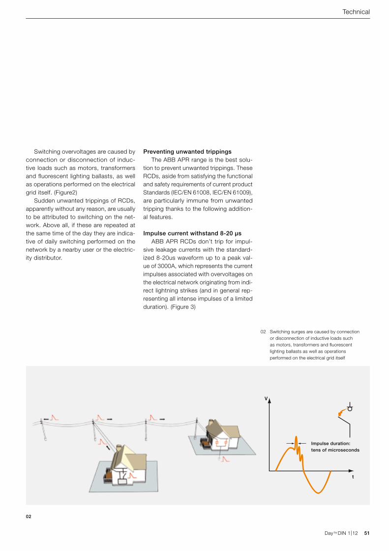
t
V
Impulse duration: tens of microseconds
Day by DIN 1|12 51Day by DIN 1|12
Technical
Switching overvoltages are caused by connection or disconnection of induc-tive loads such as motors, transformers and fluorescent lighting ballasts, as well as operations performed on the electrical grid itself. (Figure2) Sudden unwanted trippings of RCDs, apparently without any reason, are usually to be attributed to switching on the net-work. Above all, if these are repeated at the same time of the day they are indica-tive of daily switching performed on the network by a nearby user or the electric-ity distributor.
Preventing unwanted trippings The ABB APR range is the best solu-tion to prevent unwanted trippings. These RCDs, aside from satisfying the functional and safety requirements of current product Standards (IEC/EN 61008, IEC/EN 61009), are particularly immune from unwanted tripping thanks to the following addition-al features.
Impulse current withstand 8-20 µs ABB APR RCDs don’t trip for impul-sive leakage currents with the standard-ized 8-20us waveform up to a peak val-ue of 3000A, which represents the current impulses associated with overvoltages on the electrical network originating from indi-rect lightning strikes (and in general rep-resenting all intense impulses of a limited duration). (Figure 3)
02
02 Switching surges are caused by connection or disconnection of inductive loads such as motors, transformers and fluorescent lighting ballasts as well as operations performed on the electrical grid itself
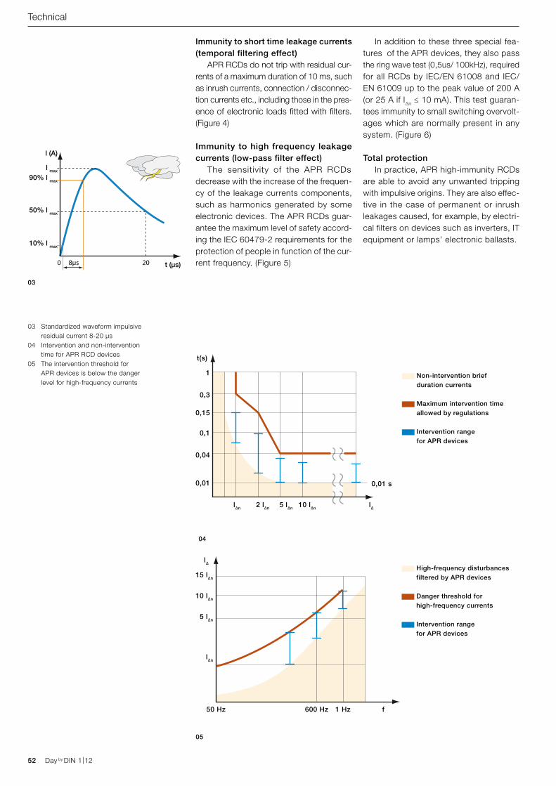
t (μs)
l (A)
l max
90% l max
50% l max
10% l max
0 8µs 20
l∆n 2 l∆n 5 l∆n 10 l∆n l∆
0,01 s
1
0,3
0,15
0,1
0,04
0,01
t(s)
50 Hz 600 Hz 1 Hz f
15 l∆n
10 l∆n
5 l∆n
l∆n
l∆
Non-intervention brief duration currents
Maximum intervention time allowed by regulations
Intervention range for APR devices
High-frequency disturbances filtered by APR devices
Danger threshold for high-frequency currents
Intervention range for APR devices
52 Day by DIN 1|12 Day by DIN 1|12
Technical
Immunity to short time leakage currents (temporal filtering effect) APR RCDs do not trip with residual cur-rents of a maximum duration of 10 ms, such as inrush currents, connection / disconnec-tion currents etc., including those in the pres-ence of electronic loads fitted with filters. (Figure 4)
Immunity to high frequency leakage currents (low-pass filter effect) The sensitivity of the APR RCDs decrease with the increase of the frequen-cy of the leakage currents components, such as harmonics generated by some electronic devices. The APR RCDs guar-antee the maximum level of safety accord-ing the IEC 60479-2 requirements for the protection of people in function of the cur-rent frequency. (Figure 5)
In addition to these three special fea-tures of the APR devices, they also pass the ring wave test (0,5us/ 100kHz), required for all RCDs by IEC/EN 61008 and IEC/EN 61009 up to the peak value of 200 A (or 25 A if I∆n ≤ 10 mA). This test guaran-tees immunity to small switching overvolt-ages which are normally present in any system. (Figure 6)
Total protection In practice, APR high-immunity RCDs are able to avoid any unwanted tripping with impulsive origins. They are also effec-tive in the case of permanent or inrush leakages caused, for example, by electri-cal filters on devices such as inverters, IT equipment or lamps’ electronic ballasts.
03
04
05
03 Standardized waveform impulsive residual current 8-20 µs
04 Intervention and non-intervention time for APR RCD devices
05 The intervention threshold for APR devices is below the danger level for high-frequency currents
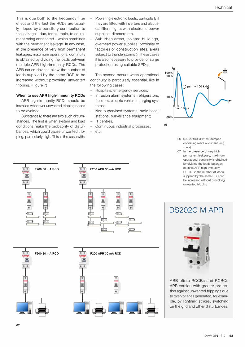
100%90%
10%
60%
c.a. 0.5 μs
10 μs (f = 100 kHz)
t
I
F200 30 mA RCD
F200 30 mA RCD
F200 APR 30 mA RCD
F200 APR 30 mA RCD
ABB offers RCCBs and RCBOs APR version with greater protec-tion against unwanted trippings due to overvoltages generated, for exam-ple, by lightning strikes, switching on the grid and other disturbances.
DS202C M APR
Day by DIN 1|12 53Day by DIN 1|12
Technical
This is due both to the frequency filter effect and the fact the RCDs are usual-ly tripped by a transitory contribution to the leakage – due, for example, to equip-ment being connected – which combines with the permanent leakage. In any case, in the presence of very high permanent leakages, maximum operational continuity is obtained by dividing the loads between multiple APR high-immunity RCDs. The APR series devices allow the number of loads supplied by the same RCD to be increased without provoking unwanted tripping. (Figure 7)
When to use APR high-immunity RCDs APR high-immunity RCDs should be installed whenever unwanted tripping needs to be avoided. Substantially, there are two such circum-stances. The first is when system and load conditions make the probability of distur-bances, which could cause unwanted trip-ping, particularly high. This is the case with:
− Powering electronic loads, particularly if they are fitted with inverters and electri-cal filters, lights with electronic power supplies, dimmers etc.
− Suburban areas, isolated buildings, overhead power supplies, proximity to factories or construction sites, areas subject to thunderstorms (in these cases it is also necessary to provide for surge protection using suitable SPDs).
The second occurs when operational continuity is particularly essential, like in the following cases:
− Hospitals, emergency services; − Intrusion alarm systems, refrigerators,
freezers, electric vehicle charging sys-tems;
− Non-supervised systems, radio base-stations, surveillance equipment;
− IT centres; − Continuous industrial processes; − etc.
06
06 0.5 µs/100 kHz test damped oscillating residual current (ring wave)
07 In the presence of very high permanent leakages, maximum operational continuity is obtained by dividing the loads between multiple APR high-immunity RCDs. So the number of loads supplied by the same RCD can be increased without provoking unwanted tripping
07
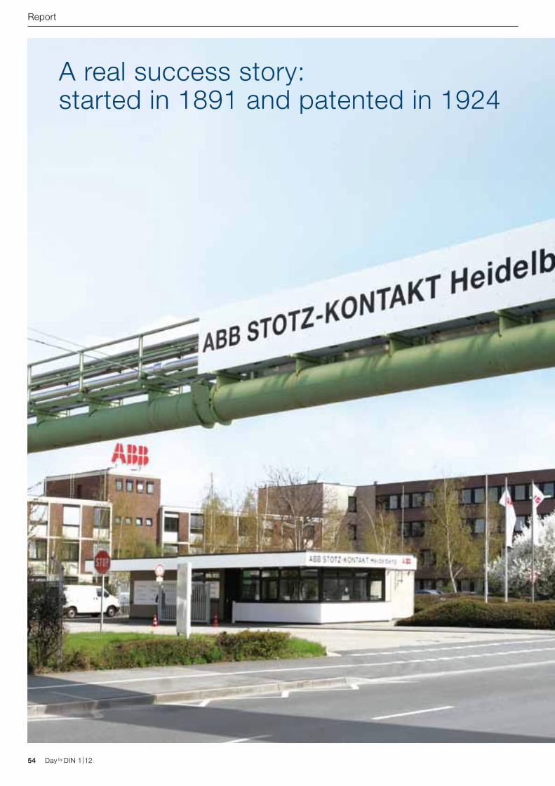
54 Day by DIN 1|12 Day by DIN 1|12
A real success story: started in 1891 and patented in 1924
Report
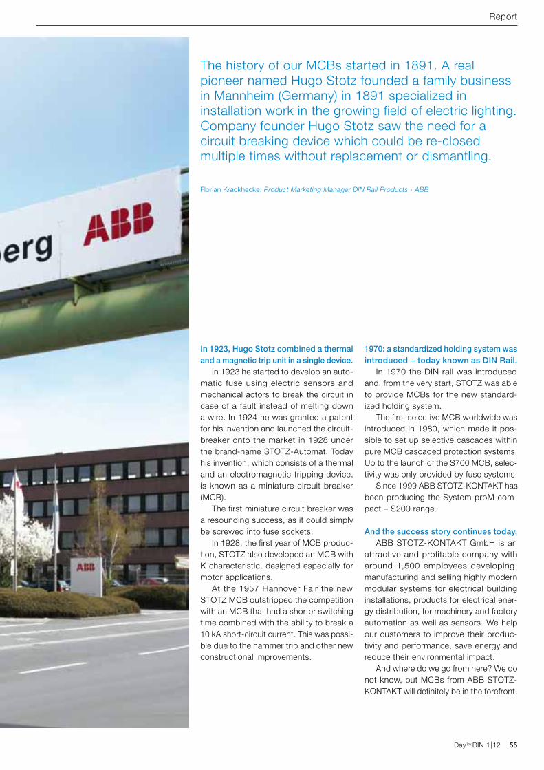
Day by DIN 1|12 55Day by DIN 1|12
Report
In 1923, Hugo Stotz combined a thermal and a magnetic trip unit in a single device. In 1923 he started to develop an auto-matic fuse using electric sensors and mechanical actors to break the circuit in case of a fault instead of melting down a wire. In 1924 he was granted a patent for his invention and launched the circuit-breaker onto the market in 1928 under the brand-name STOTZ-Automat. Today his invention, which consists of a thermal and an electromagnetic tripping device, is known as a miniature circuit breaker (MCB). The first miniature circuit breaker was a resounding success, as it could simply be screwed into fuse sockets. In 1928, the first year of MCB produc-tion, STOTZ also developed an MCB with K characteristic, designed especially for motor applications. At the 1957 Hannover Fair the new STOTZ MCB outstripped the competition with an MCB that had a shorter switching time combined with the ability to break a 10 kA short-circuit current. This was possi-ble due to the hammer trip and other new constructional improvements.
1970: a standardized holding system was introduced − today known as DIN Rail. In 1970 the DIN rail was introduced and, from the very start, STOTZ was able to provide MCBs for the new standard-ized holding system. The first selective MCB worldwide was introduced in 1980, which made it pos-sible to set up selective cascades within pure MCB cascaded protection systems. Up to the launch of the S700 MCB, selec-tivity was only provided by fuse systems. Since 1999 ABB STOTZ-KONTAKT has been producing the System proM com-pact – S200 range.
And the success story continues today. ABB STOTZ-KONTAKT GmbH is an attractive and profitable company with around 1,500 employees developing, manufacturing and selling highly modern modular systems for electrical building installations, products for electrical ener-gy distribution, for machinery and factory automation as well as sensors. We help our customers to improve their produc-tivity and performance, save energy and reduce their environmental impact. And where do we go from here? We do not know, but MCBs from ABB STOTZ-KONTAKT will definitely be in the forefront.
The history of our MCBs started in 1891. A real pioneer named Hugo Stotz founded a family business in Mannheim (Germany) in 1891 specialized in installation work in the growing field of electric lighting. Company founder Hugo Stotz saw the need for a circuit breaking device which could be re-closed multiple times without replacement or dismantling.
Florian Krackhecke: Product Marketing Manager DIN Rail Products - ABB
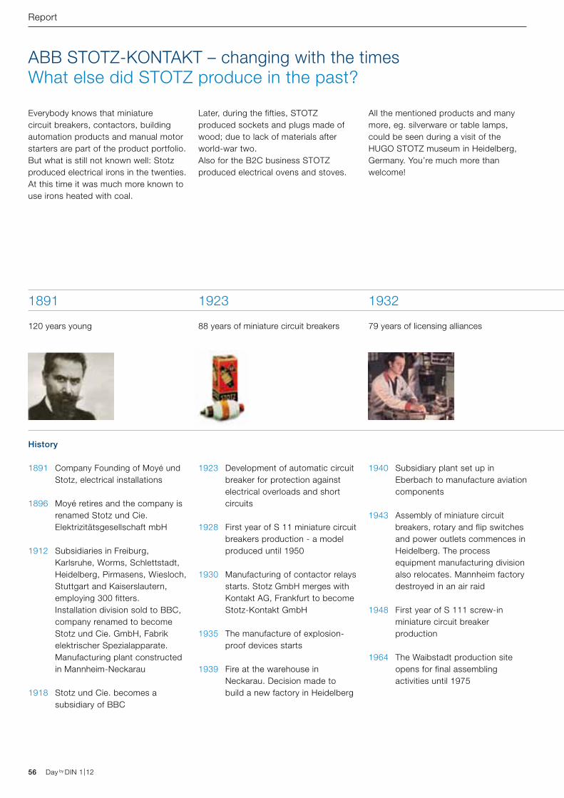
56 Day by DIN 1|12 Day by DIN 1|12
Report
1891 Company Founding of Moyé und Stotz, electrical installations
1896 Moyé retires and the company is renamed Stotz und Cie. Elektrizitäts gesellschaft mbH
1912 Subsidiaries in Freiburg, Karlsruhe, Worms, Schlettstadt, Heidelberg, Pirmasens, Wiesloch, Stuttgart and Kaiserslautern, employing 300 fitters. Installation division sold to BBC, company renamed to become Stotz und Cie. GmbH, Fabrik elektrischer Spezialapparate. Manufacturing plant constructed in Mannheim-Neckarau
1918 Stotz und Cie. becomes a subsidiary of BBC
ABB STOTZ-KONTAKT – changing with the timesWhat else did STOTZ produce in the past?
History
1923 Development of automatic circuit breaker for protection against electrical overloads and short circuits
1928 First year of S 11 miniature circuit breakers production - a model produced until 1950
1930 Manufacturing of contactor relays starts. Stotz GmbH merges with Kontakt AG, Frankfurt to become Stotz-Kontakt GmbH
1935 The manufacture of explosion-proof devices starts
1939 Fire at the warehouse in Neckarau. Decision made to build a new factory in Heidelberg
1940 Subsidiary plant set up in Eberbach to manufacture aviation components
1943 Assembly of miniature circuit breakers, rotary and flip switches and power outlets commences in Heidelberg. The process equipment manufacturing division also relocates. Mannheim factory destroyed in an air raid
1948 First year of S 111 screw-in miniature circuit breaker production
1964 The Waibstadt production site opens for final assembling activities until 1975
1891
120 years young
1923
88 years of miniature circuit breakers
1932
79 years of licensing alliances
Everybody knows that miniature circuit breakers, contactors, building automation products and manual motor starters are part of the product portfolio.But what is still not known well: Stotz produced electrical irons in the twenties. At this time it was much more known to use irons heated with coal.
Later, during the fifties, STOTZ produced sockets and plugs made of wood; due to lack of materials after world-war two. Also for the B2C business STOTZ produced electrical ovens and stoves.
All the mentioned products and many more, eg. silverware or table lamps, could be seen during a visit of the HUGO STOTZ museum in Heidelberg, Germany. You’re much more than welcome!
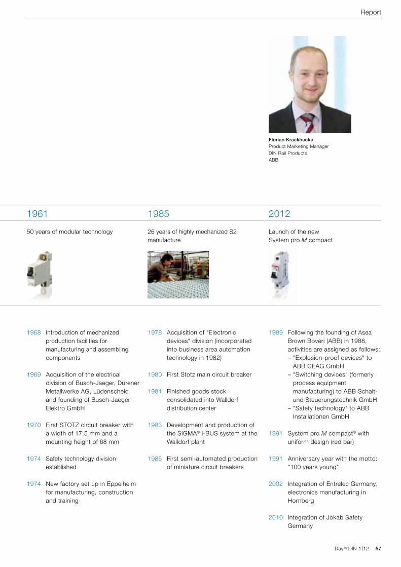
Day by DIN 1|12 57Day by DIN 1|12
Report
1968 Introduction of mechanized production facilities for manufacturing and assembling components
1969 Acquisition of the electrical division of Busch-Jaeger, Dürener Metall werke AG, Lüdenscheid and founding of Busch-Jaeger Elektro GmbH
1970 First STOTZ circuit breaker with a width of 17.5 mm and a mounting height of 68 mm
1974 Safety technology division established
1974 New factory set up in Eppelheim for manufacturing, construction and training
1978 Acquisition of "Electronic devices" division (incorporated into business area automation technology in 1982)
1980 First Stotz main circuit breaker
1981 Finished goods stock consolidated into Walldorf distribution center
1983 Development and production of the SIGMA® i-BUS system at the Walldorf plant
1985 First semi-automated production of miniature circuit breakers
1989 Following the founding of Asea Brown Boveri (ABB) in 1988, activities are assigned as follows: – "Explosion-proof devices" to
ABB CEAG GmbH – "Switching devices" (formerly
process equipment manufacturing) to ABB Schalt- und Steuerungs technik GmbH
– "Safety technology" to ABB Installationen GmbH
1991 System pro M compact® with uniform design (red bar)
1991 Anniversary year with the motto: "100 years young"
2002 Integration of Entrelec Germany, electronics manufacturing in Hornberg
2010 Integration of Jokab Safety Germany
1961
50 years of modular technology
1985
26 years of highly mechanized S2 manufacture
2012
Launch of the new System pro M compact
Florian KrackheckeProduct Marketing Manager DIN Rail ProductsABB
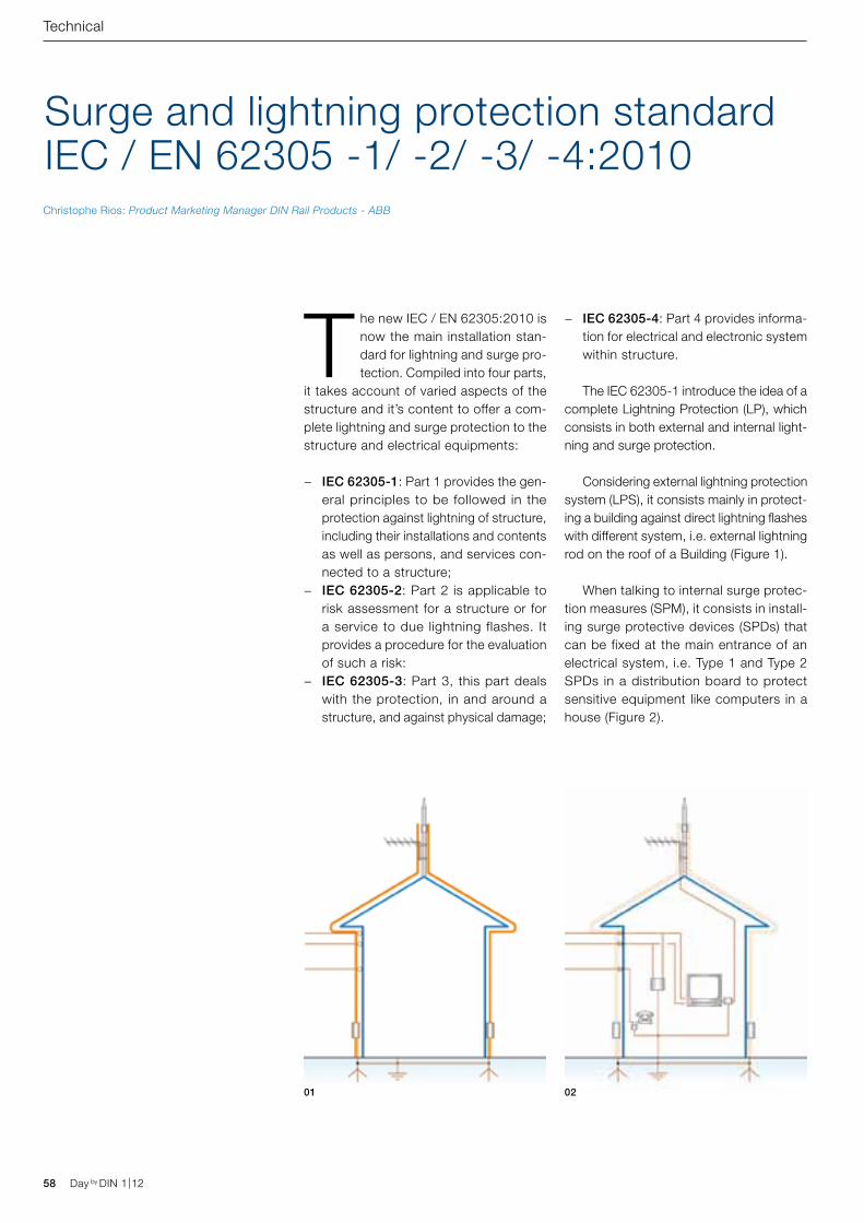
58 Day by DIN 1|12 Day by DIN 1|12
Surge and lightning protection standardIEC / EN 62305 -1/ -2/ -3/ -4:2010
Technical
The new IEC / EN 62305:2010 is now the main installation stan-dard for lightning and surge pro-tection. Compiled into four parts,
it takes account of varied aspects of the structure and it’s content to offer a com-plete lightning and surge protection to the structure and electrical equipments:
− IEC 62305-1: Part 1 provides the gen-eral principles to be followed in the protection against lightning of structure, including their installations and contents as well as persons, and services con-nected to a structure;
− IEC 62305-2: Part 2 is applicable to risk assessment for a structure or for a service to due lightning flashes. It provides a procedure for the evaluation of such a risk:
− IEC 62305-3: Part 3, this part deals with the protection, in and around a structure, and against physical damage;
− IEC 62305-4: Part 4 provides informa-tion for electrical and electronic system within structure.
The IEC 62305-1 introduce the idea of a complete Lightning Protection (LP), which consists in both external and internal light-ning and surge protection.
Considering external lightning protection system (LPS), it consists mainly in protect-ing a building against direct lightning flashes with different system, i.e. external lightning rod on the roof of a Building (Figure 1).
When talking to internal surge protec-tion measures (SPM), it consists in install-ing surge protective devices (SPDs) that can be fixed at the main entrance of an electrical system, i.e. Type 1 and Type 2 SPDs in a distribution board to protect sensitive equipment like computers in a house (Figure 2).
Christophe Rios: Product Marketing Manager DIN Rail Products - ABB
01 02
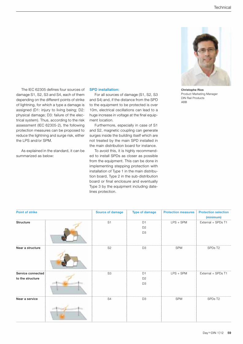
Day by DIN 1|12 59Day by DIN 1|12
Technical
The IEC 62305 defines four sources of damage S1, S2, S3 and S4, each of them depending on the different points of strike of lightning, for which a type a damage is assigned (D1: injury to living being; D2: physical damage; D3: failure of the elec-trical system). Thus, according to the risk assessment (IEC 62305-2), the following protection measures can be proposed to reduce the lightning and surge risk, either the LPS and/or SPM.
As explained in the standard, it can be summarized as below:
SPD installation: For all sources of damage (S1, S2, S3 and S4) and, if the distance from the SPD to the equipment to be protected is over 10m, electrical oscillations can lead to a huge increase in voltage at the final equip-ment location. Furthermore, especially in case of S1 and S2, magnetic coupling can generate surges inside the building itself which are not treated by the main SPD installed in the main distribution board for instance. To avoid this, it is highly recommend-ed to install SPDs as closer as possible from the equipment. This can be done in implementing stepping protection with installation of Type 1 in the main distribu-tion board, Type 2 in the sub-distribution board or final enclosure and eventually Type 3 by the equipment including date-lines protection.
Point of strike Source of damage Type of damage Protection measures Protection selection
(minimum)
Structure S1 D1
D2
D3
LPS + SPM External + SPDs T1
Near a structure S2 D3 SPM SPDs T2
Service connected
to the structure
S3 D1
D2
D3
LPS + SPM External + SPDs T1
Near a service S4 D3 SPM SPDs T2
Christophe RiosProduct Marketing Manager DIN Rail ProductsABB
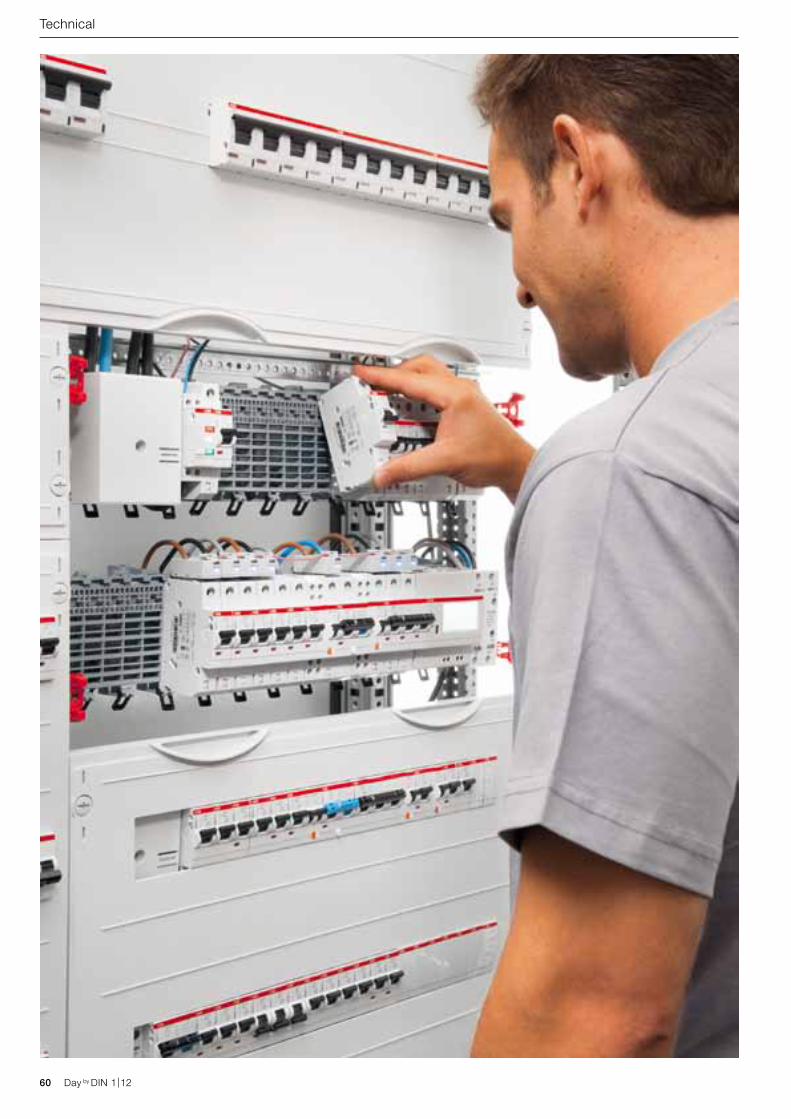
60 Day by DIN 1|12 Day by DIN 1|12
Technical
Day by DIN 1|12 61Day by DIN 1|12
Technical
A progressive solution should not only be technically sound but must also be viable in day-to-day operation. In our fast-
moving world, in which technology chan-ges at such a rapid rate, we need solutions that work in the long term.
Loss of Power is a risk factor for human, electrical process and electrical equipment. Energy must today be available all the time. The security and prevention of human is very important and the technical stuff has to fol-low the regulations and lows. There are systems available which allow the devices to be plugged and unplugged load free under power without any risk from electrical current running through the body. This should be confirmed by the German Employers’ Liability Insurance Association or electrosuisse.
Safety when working with live equipment Those pluggable systems should be designed in such a way that changes or extensions to the system can be carried out during operation. Today in many sys-tems or buildings, it is not easy to interrupt the power supply to work on systems. The touch-safe system makes this situa-tion much easier. It allows devices and com-ponents to be plugged in and unplugged load-free live without additional personal protective equipment to protect against electrical risks. When devices are plugged and unplugged without load, there can’t be any risk of electric shock. When the devices are plugged and unplugged, the system is fully touch-proof, means it is completely finger-safe (IP2XB).
An electrical system must meet all the requirements for planning, design and maintenance throughout its entire life cycle. With systems that are operating all the time, the problem often arises that extensions or modifications need to be carried out whilst the system is live. Working on live systems is basically possible, but in practice this involves a considerable number of (safety) measures. A touch-proof socket system that allows load-free working under live conditions without personal protective equipment would be the best solution. This can crucially reduce the costs during the entire life cycle of a system, whilst at the same time offering increased protection for personnel.
SMISSLINE TP – Power and safety
01 Working under power
Malvin Lingwood: Product Marketing Manager DIN Rail Products - ABB
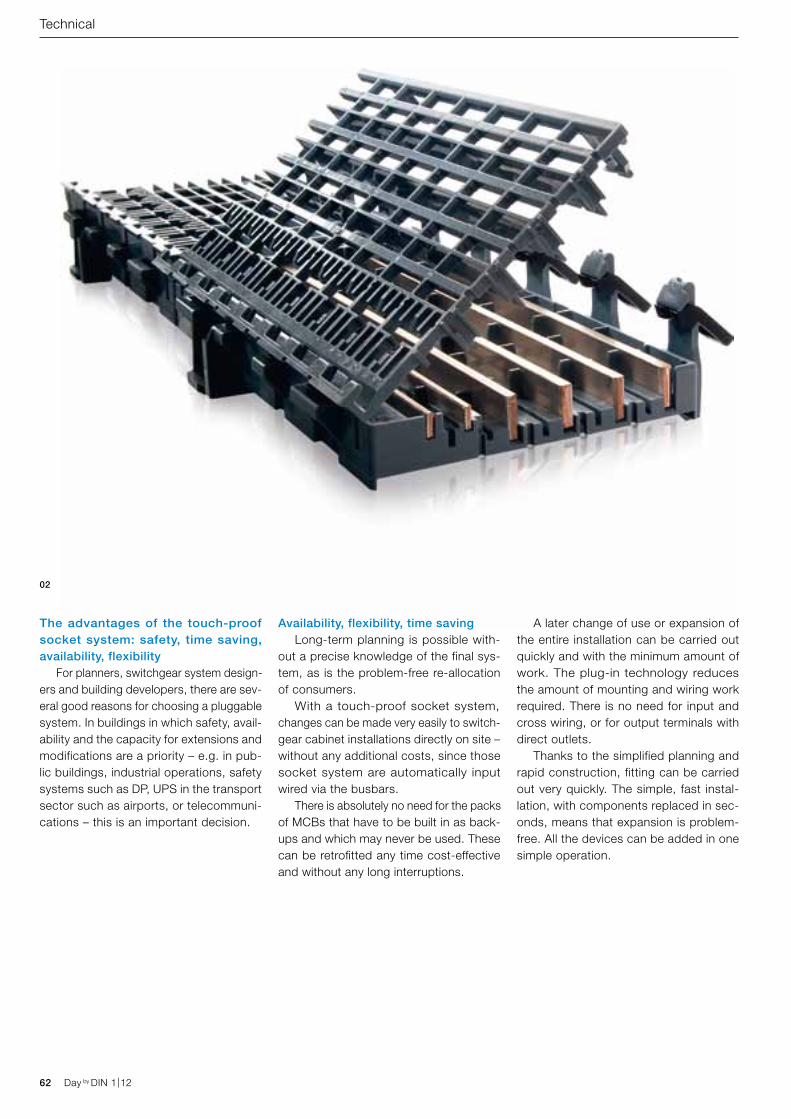
62 Day by DIN 1|12 Day by DIN 1|12
Availability, flexibility, time saving Long-term planning is possible with-out a precise knowledge of the final sys-tem, as is the problem-free re-allocation of consumers. With a touch-proof socket system, changes can be made very easily to switch-gear cabinet installations directly on site – without any additional costs, since those socket system are automatically input wired via the busbars. There is absolutely no need for the packs of MCBs that have to be built in as back-ups and which may never be used. These can be retrofitted any time cost-effective and without any long interruptions.
A later change of use or expansion of the entire installation can be carried out quickly and with the minimum amount of work. The plug-in technology reduces the amount of mounting and wiring work required. There is no need for input and cross wiring, or for output terminals with direct outlets. Thanks to the simplified planning and rapid construction, fitting can be carried out very quickly. The simple, fast instal-lation, with components replaced in sec-onds, means that expansion is problem-free. All the devices can be added in one simple operation.
Technical
The advantages of the touch-proof socket system: safety, time saving, availability, flexibility For planners, switchgear system design-ers and building developers, there are sev-eral good reasons for choosing a pluggable system. In buildings in which safety, avail-ability and the capacity for extensions and modifications are a priority – e.g. in pub-lic buildings, industrial operations, safety systems such as DP, UPS in the transport sector such as airports, or telecommuni-cations – this is an important decision.
02
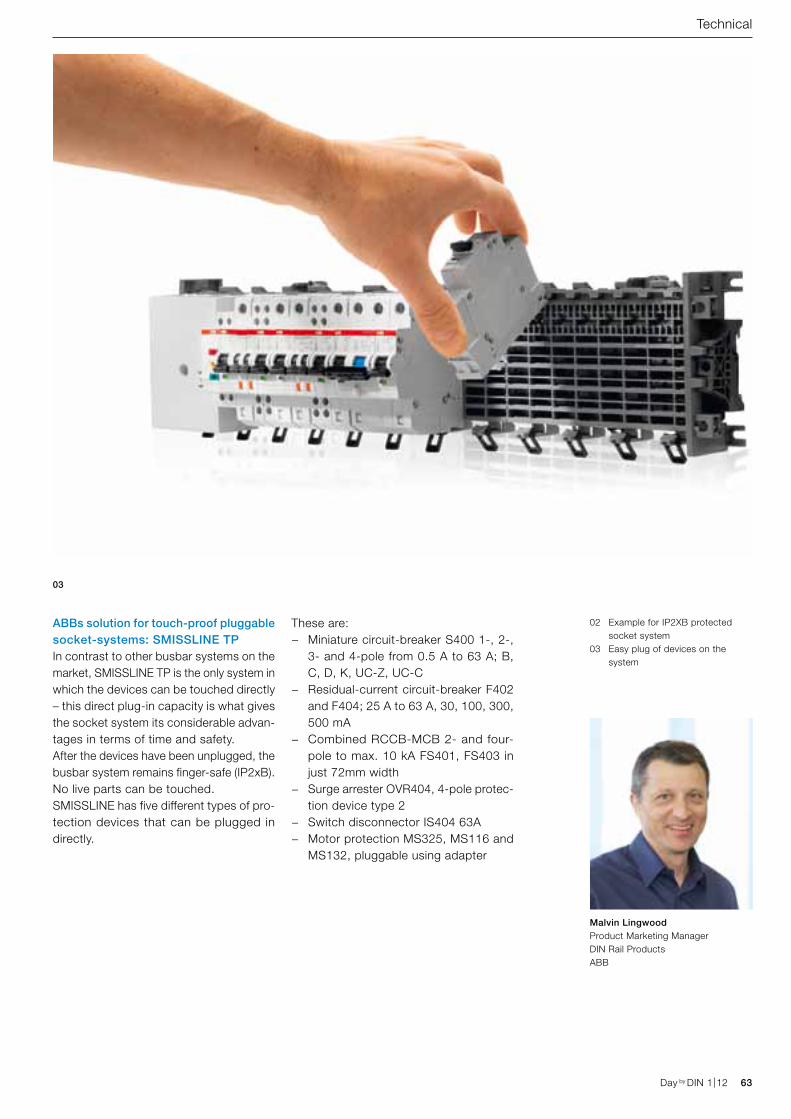
02 Example for IP2XB protected socket system
03 Easy plug of devices on the system
Day by DIN 1|12 63Day by DIN 1|12
ABBs solution for touch-proof pluggable socket-systems: SMISSLINE TPIn contrast to other busbar systems on the market, SMISSLINE TP is the only system in which the devices can be touched directly – this direct plug-in capacity is what gives the socket system its considerable advan-tages in terms of time and safety.After the devices have been unplugged, the busbar system remains finger-safe (IP2xB). No live parts can be touched. SMISSLINE has five different types of pro-tection devices that can be plugged in directly.
These are: − Miniature circuit-breaker S400 1-, 2-,
3- and 4-pole from 0.5 A to 63 A; B, C, D, K, UC-Z, UC-C
− Residual-current circuit-breaker F402 and F404; 25 A to 63 A, 30, 100, 300, 500 mA
− Combined RCCB-MCB 2- and four-pole to max. 10 kA FS401, FS403 in just 72mm width
− Surge arrester OVR404, 4-pole protec-tion device type 2
− Switch disconnector IS404 63A − Motor protection MS325, MS116 and
MS132, pluggable using adapter
Technical
03
Malvin LingwoodProduct Marketing Manager DIN Rail ProductsABB
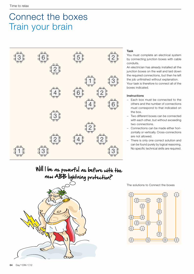
3 6 5 2
31
24 6
2
331
4 6
2
2
3
2 4
3652
3 1
2 46
2
3 3 1
46
2
2
3
24
64 Day by DIN 1|12
Connect the boxesTrain your brain
Time to relax
Will I be as powerful as before with the new ABB lightning protection?
TaskYou must complete an electrical system by connecting junction boxes with cable conduits. An electrician has already installed all the junction boxes on the wall and laid down the required connections, but then he left the job unfinished without explanation.Your task is therefore to connect all of the boxes indicated.
Instructions − Each box must be connected to the
others and the number of connections must correspond to that indicated on the box.
− Two different boxes can be connected with each other, but without exceeding two connections.
− Connections can be made either hori-zontally or vertically. Cross-connections are not allowed.
− There is only one correct solution and can be found purely by logical reasoning. No specific technical skills are required.
The solutions to Connect the boxes
Day by DIN 1|12
E210. Set new standards in your electrical distribution board
ABB expands E210 range with new 2 and 3 LED indicator lights. E210 allows users to save valuable space in distribution boards thanks to narrow 9 mm width. E210 range is made for consumer units, large scale switchgear, commercial buildings and industrial control systems. The new 2 and 3 LED indicator lights are ideal in alarm and status indication of loads and switches and voltage presence. The ABB range encompasses on-off, change over, group and control switches, as well as pushbuttons with and without LEDs and a variety of indicator lights. E210 meets the most important related standards EN 60669-1, EN 60669-2-4, EN 62094-1 and UL 508. www.abb.com
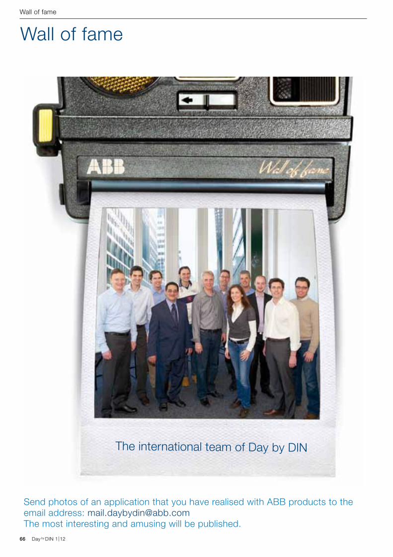
66 Day by DIN 1|12
Wall of fame
Wall of fame
The international team of Day by DIN
Send photos of an application that you have realised with ABB products to the email address: [email protected] The most interesting and amusing will be published.
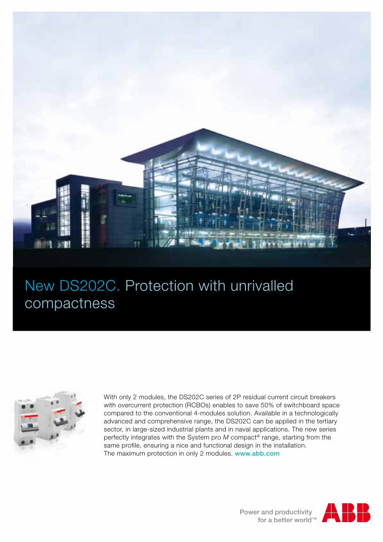
Day by DIN 1|12
New DS202C. Protection with unrivalled compactness
With only 2 modules, the DS202C series of 2P residual current circuit breakers with overcurrent protection (RCBOs) enables to save 50% of switchboard space compared to the conventional 4-modules solution. Available in a technologically advanced and comprehensive range, the DS202C can be applied in the tertiary sector, in large-sized industrial plants and in naval applications. The new series perfectly integrates with the System pro M compact® range, starting from the same profile, ensuring a nice and functional design in the installation. The maximum protection in only 2 modules. www.abb.com
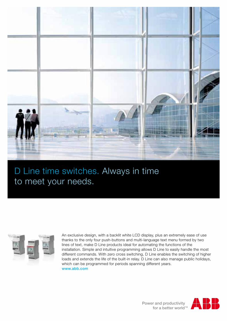
D Line time switches. Always in time to meet your needs.
An exclusive design, with a backlit white LCD display, plus an extremely ease of use thanks to the only four push-buttons and multi-language text menu formed by two lines of text, make D Line products ideal for automating the functions of the installation. Simple and intuitive programming allows D Line to easily handle the most different commands. With zero cross switching, D Line enables the switching of higher loads and extends the life of the built-in relay. D Line can also manage public holidays, which can be programmed for periods spanning different years.www.abb.com