Embed Size (px)
Citation preview

39
*Corresponding author: F.J.Martinez Monseco, [email protected]
1. IntroductionIn order to produce electric energy by means of a hydroelectric power station, it can be considered that the failures of the turbine system of a hydroelectric group impact considerably in the reliability and availability of the electric generation system, causing unavailability in the medium and long term, as well as the necessity of having to plan in an unscheduled way works in the hydroelectric groups of great economic impact and loss of utilities (overhaul, total or partial dismantling, request of supply of singular pieces with long term of manufacture).
The objective of the article is to implement a maintenance optimization process of the turbine system (one of the most important systems of the hydroelectric group), starting from the current state of the maintenance strategy with stops of the group (unavailability in terms of operation) at a defined frequency (quarterly, annual) until a new strategy of greater control in continuous conditions and, based on this control, to be able to define actions that imply technical and economic improvements in terms of the maintenance strategy to be applied.
A hydropower plant is a facility that uses hydraulic energy for the generation of electric power. These plants use the potential gravitational energy that the water mass of a natural course possesses by virtue of a difference in level, also known as “geodesic jump” (Gulliver & Arndt, 1991). When falling between two river levels, the water passes through a hydraulic turbine that transmits the energy to an electric generator where it is transformed into electric energy.
2. Turbine systemThe water turbine converts the energy of a waterfall into mechanical energy. The turbine-generator set is usually called a hydroelectric group, and depending on the height of the falls, the flow rates and the energy needs, there are different types of turbines.
2.1. Function of the turbine system
The water turbine is a water-powered rotary machine. In this way it converts the hydraulic energy of a stream or waterfall into mechanical energy (Gulliver & Arndt, 1991). The basic element of the turbine is the impeller, which has blades or propellers placed around its circumference in such a way that the moving fluid, on impact, produces a tangential force that drives the impeller and makes it spin. The rotation is transferred through its axis to move any machine coupled to it. The hydraulic turbine turns the generator rotor, which transforms the mechanical energy that moves the turbine shaft into electrical energy.
2.2. Subsystems and equipment
The Turbine System can be subdivided into the following subsystems or equipment indicated in Table 1. Figures 2, 3 and 4 show different parts of the turbine system.
The different equipments of the turbine system are (Gulliver & Arndt, 1991):
Spiral case: This is the conduit that transports the water from the forced pipe to the turbine. Its shape makes the
AN APPROACH TO A MAINTENANCE PLAN FOR A TURBINE OF HYDROELECTRIC POWER PLANT. OPTIMISATION BASED IN RCM AND
FMECA ANALYSISFrancisco Javier Martinez-Monseco
Escuela Técnica Superior de Ingenieros ETSI-UNED, Madrid. Spain.
Manager of the hydroelectric plants of Barcelona and Girona (Ter Unit) of the company Enel Green Power Iberia Hydro. Spain.
Abstract:
The generation of electric energy is a continuous process of great strategic importance in the development of countries. The evolution in the last decades of different environmental control protocols at a global level has influenced the rise of renewable energies with low impact on the environment. These reasons make it important that this process has an effective maintenance management system that guarantees adequate reliability, availability and useful life of its assets. This article describes the implementation of the optimization of the traditional preventive maintenance that is carried out in regular temporary intervals with unavailability of the hydroelectric group, to be able to take advantage of the data base of operation of the group (failure modes, criticality, application of maintenance strategies to condition and maintenance 4.0, etc…).
Keywords: Maintenance, Reliability, Power plants, Industrial processes.
Cite as: Martinez-Monseco, F.J. (2021). An approach to a maintenance plan for a turbine of hydroelectric power plant. Optimisation based in RCM and FMECA analysis. J Appl Res Eng Technol & Engineering, 2(1), 39-50. https://doi.org/10.4995/jarte.2021.14761
2(1): 39-50, 2021https://doi.org/10.4995/jarte.2021.14761
Received: December 09, 2020; Accepted: January 14, 2021; Published: January 31, 2021
Journal of Applied Research in Technology & Engineering
Francisco J. Martinez-Monseco, 2021
Journal of Applied Research in Technology & Engineering, 2(1): 39-50, 202140
liquid circulate with uniform speed and without forming whirls. In addition, the section gradually decreases as it goes through the turbine to increase the speed of the water, the latter being the maximum at the outlet of the impeller. In the internal peripheral area, concentric to the impeller, there is a series of fixed blades that are responsible for directing the water almost radially towards the distributor (before the distributor).
Distributor: made up of a number of mobile blades connected by a ring. Its function is to distribute and regulate the water flowing to the impeller in accordance with the orders of the speed regulator.
Speed regulator: to move the distributor’s blades, great efforts are required, which are provided by servomotors. They are driven by high pressure oil circuits which are controlled by the speed regulator. This element, by means of mechanical or electronic means, detects the real speed of the G and causes the adjustment of the distributor to maintain the constant speed.
Suction pipe: angled pipe that links the turbine to the drainage channel. It is designed so that the outlet pressure of the impeller is lower than the atmospheric pressure. This depression sucks in water that leaves the turbine, recovering the kinetic energy that the liquid has at the entrance of the impeller, increasing the performance of the turbine.
Turbine shaft: transmits to the alternator rotor the movement required to generate electrical energy. The shaft is fitted with a thrust bearing that supports the weight of the assembly. An oil circuit lubricates its parts by passing the oil through a heat exchanger to keep it cool.
Guide bearing: it is in charge of reducing the vibration of the shaft and maintaining its position. It also has an oil cooling system. A shaft sealing system prevents water from leaking out of the turbine. It consists of carbon or graphite seals that close around the shaft, cooled by a pressurised water system that also helps to prevent water access from the impeller.
Turbine protection: Protection equipment based on mechanical effects producing alarms, trips or signals of different parameters. The protection equipment are thermostats, thermometers, pressure switches, level detectors, flow meters, tachometers, control system relays, etc.
Figure 2: Distributor and turbine blades. (Source Endesa Generación-Enel Green Power).
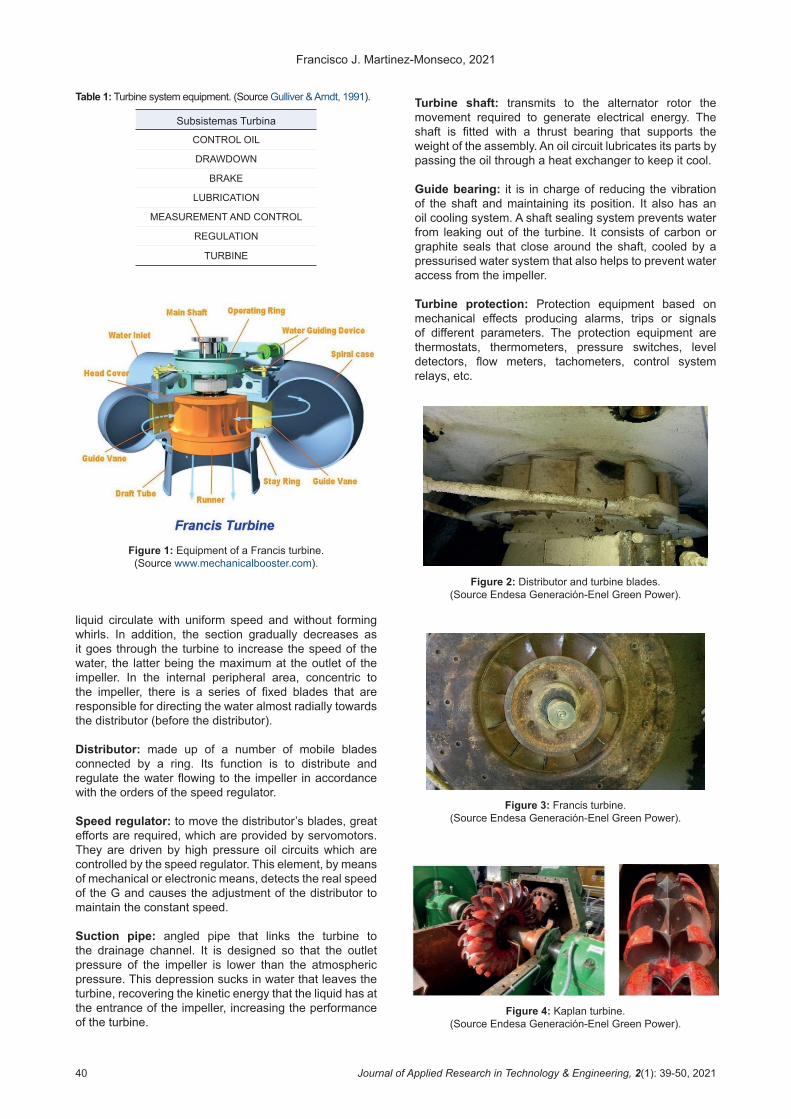
Figure 3: Francis turbine. (Source Endesa Generación-Enel Green Power).
Figure 4: Kaplan turbine. (Source Endesa Generación-Enel Green Power).
Table 1: Turbine system equipment. (Source Gulliver & Arndt, 1991).
Subsistemas Turbina
CONTROL OIL
DRAWDOWN
BRAKE
LUBRICATION
MEASUREMENT AND CONTROL
REGULATION
TURBINE
Figure 1: Equipment of a Francis turbine. (Source www.mechanicalbooster.com).

An approach to a maintenance plan for a turbine of hydroelectric power plant. Optimisation based in RCM and FMECA analysis
Journal of Applied Research in Technology & Engineering, 2(1): 39-50, 2021 41
3. Methodology
The research of this paper is based on these actions in the turbine system and its equipment:
• Analysis of incidents in the turbine system in a universe of incidents of hydroelectric groups.
• Identification of failure modes, failure types and root causes.
• Classification and prioritisation of failure modes.• Determination of the maintenance strategy.• Establishment of the proposed tasks.• Consolidation of proposals.
4. Analysis of turbine system incidents
Through a universe of hydroelectric plants and the incidents that occurred in a temporary period of 10 years, information can be obtained regarding the different typology of the incidents for each system of the hydroelectric group as well as the incidents of the turbine system to determine the criticality of each failure and to be able to prioritize the actions to be carried out with a limited economic budget by the management of any company as opposed to the maintenance department (Egusquiza et al., 1994; Martinez Monseco, 2013; 2016). Table 2 shows the characteristics of hydroelectric power plants.
Table 2: Characteristics of the hydroelectric power stations analysed. (Source: data for current doctoral research
Martinez Monseco, 2016).
Hydroelectric power plants analysed109 plants Installed power
3461 MWAverage hours
operation per group 6739 h
203 hydro groups Average power per group 31 MW
Annual operating rate per group 78%
The following Figures 5 and 6 show a distribution chart of the different incidents for each system of the hydroelectric group (Martinez Montero, 2013, 2016, 2020). As can be seen, incidents in the turbine system have a significant weight in the total number of incidents in the plants analysed (29% of the total number of incidents analysed).
11% 1%; 2% 9%
28%7%2%
10%
1%
29%
% HYDROELECTRIC POWER PLANTS INCIDENTS
ALTERNATOR
HIGH VOLTAGE MANEUVER
GENERATOR VOLTAGE CONTROL
GUARD ORGAN
PROTECTIONS
REFRIGERATION
AUXILIARY SERVICES
TELECONTROL
TRANSFORMER
TURBINE
Figure 5: hydroelectric power plants incidents. (Source: data for current doctoral research Martinez Monseco, 2016).
376 368
142 125 12092
28 25 18 9
TURB
INE
PRO
TECT
ION
S
ALTE
RNAT
OR
TELE
CON
TRO
L
GUAR
D O
RGAN
REFR
IGER
ATIO
N
GEN
ERAT
OR …
AUXI
LIAR
Y SE
RVIC
ES
TRAN
SFO
RMER
HIGH
VO
LTAG
E …
HYDROELECTRIC POWER PLANTS INCIDENTS
Figure 6: Distribution of incidents by systems equipment in hydro power plant. (Source: data for current doctoral research
Martinez Monseco, 2016).
Figure 7 shows the pareto diagram of the classified incidents (%) in each of the subsystems or equipment that make up the turbine system.
Through the information reflected, it can be clearly seen that the most significant incidents occur in the next subsystems:
1. Measurement and control.2. Regulation.3. Turbine.4. Lubrication.
MEASUREMENT
REGULATIONTURBINE
LUBRICATION
CONTROL OIL
DRAWDOWNBRAKE
020406080
100120140160
0%
20%
40%
60%
80%
100%
INCIDENTS OF TURBINE SYSTEM EQUIPMENT
Figure 7: Pareto distribution diagram of hydroelectric power plant incidents in turbine system. (Source: data for current
doctoral research Martinez Monseco, 2016).
5. Analysis of failure modes and effects of the turbine system
A quantitative or qualitative method of analysis that consists of analysing failure modes and their effects by considering their probability of occurrence and the severity of their effects (Bloom, 2016; Moubray, 1997).

Francisco J. Martinez-Monseco, 2021
Journal of Applied Research in Technology & Engineering, 2(1): 39-50, 202142
5.1. Function
Before defining what process to apply to determine what needs to be done to ensure that any physical asset continues to do what its users want it to do in its operational context, two things need to be done:
• Determine what your users want you to do.• Assure that it is capable of doing what its users want
it to do.
5.2. Functional failure
The maintenance objectives are defined by the operational expectations associated with the asset (Moubray, 1997; Sifonte and Reyes-Picknell, 2017). The only fact that can make an asset unable to function according to the parameters required by its user is some kind of failure.
The RCM process performs a two-level analysis:
• First, it identifies the circumstances that lead to the failure.
• Then it asks what events could cause the asset to fail.
5.3. Failure mode
Once the functional failure has been identified, the next step is to try to identify all the facts that may have caused each failure state (Calixto, 2016; Sifonte and Reyes-Picknell, 2017). These events are called failure modes. Possible failure modes include those that have occurred in the same or similar equipment operating in the same context.
Figures 8, 9, 10, 11, 12 and 13 show different failure effects related to the failure modes in the Turbine System.
Figure 8: Detail of turbine damage due to cavitations. (Source Endesa Generación-Enel Green Power).
Figure 9: Detail of damage to turbine distributor blades due to cavitations. (Source Endesa Generación-Enel Green Power).
5.4. Effect of failure
The fourth step of the RCM process is to list the effects of the fault, which describes what happens when each fault mode is passed (Bloom, 2016; Calixto, 2016; Moubray, 1997; Sifonte and Reyes-Picknell, 2017). This description should include all the information needed to support the assessment of the consequences of failure, such as:
• Evidence that the failure has occurred• Threats to safety or the environment caused by the
failure.• Consequences on production or operations• Physical damage caused by the failure.• What must be done to repair the fault.
Table 3 shows an example about the information of one of the incidents analysed by the amfec of the Turbine System.
Table 3: Example of FMECA analysis of turbine system. (Source: data for current doctoral research
Martinez Monseco, 2016).
System EquipmentFailure modes
Types of failure
Explanation of incidence
Turbine Control oil Maintenance failure
Lack of group operation conditions
Anomaly oil control system.
Figure 10: Detail of damage to turbine blades due to cavitations. (Source Endesa Generación-Enel Green Power).
Figure 11: Detail of damage to aeration pipes and turbine cone due to cavitations.
(Source Endesa Generación-Enel Green Power).

An approach to a maintenance plan for a turbine of hydroelectric power plant. Optimisation based in RCM and FMECA analysis
Journal of Applied Research in Technology & Engineering, 2(1): 39-50, 2021 43
Figure 12: Detail of turbine cone aeration pipes due to cavitations. (Source Endesa Generación-Enel Green Power).
Figure 13: Detail of degradation with suction and turbine aeration pipes due to cavitations.
(Source Endesa Generación-Enel Green Power).
5.5. Root cause analysis
Hydroelectric power plants are made up of many elements and therefore different types of failure can occur that can cause deterioration in their operation and reduce their useful life. Furthermore, these failures have important consequences at a productive and economic level, since they can have a high cost of repair and loss of profit. The root cause analysis allows us to find the origin of a problem by determining corrective measures to reduce its occurrence (Calixto, 2016). The importance of root cause analysis is based on the following criteria:
• Reduction of exposure to risk.• Improvement of the efficiency of processes due to the
reduction and elimination of failures.• Reduction of repair costs by identifying and correcting
chronic failure modes.• Development of a corrective action plan.• Implement a process of reviewing and monitoring
requirements to prevent the occurrence of unwanted events.
5.6. NPR (number of risk priorities). Criticality Indexes
5.6.1. �Incidence�definition�parameters.�Criticality,�cost and duration
For each incident analyzed, it has been defined:
• The economic cost that has resulted from its resolution.• The duration (hours) of the resolution of the incident.• The NPR based on the multiplication of severity index
S, occurrence index O and detection index D.
In the table of incidents analyzed in terms of indices, the colors have been defined according to their criticality (green 1-4, yellow 4-6 and red 7-10). Table 4 shows an example of this analysis.
Table 4: Example of NPR analysis of failure mode in turbine system.(Source: data for current doctoral research Martinez
Monseco, 2016).
System TURBINE
Equipment CONTROL OIL
Failure modesMAINTENANCE
FAILURE
Associated economic cost incidence (m. Euros).
10
Duration of repositioning incidence. Hr 12
Severity. Criticity of incidence (1-10) 5
Occurrence. Criticity of incidence (1-10) 6
Detection. Criticality failure (1-10) 7
Npr. Criticality level. 210
Root cause of fault modes O-M
Type of faultLACK OF GROUP
OPERATION
CONDITIONS
Explanation of incidenceANOMALY OIL
CONTROL SYSTEM
Risk analysis is a process of understanding the nature of the risk and determining the level of risk. It provides the basis for risk assessment and risk management decisions. This analysis also includes risk estimation.
The risk analysis should provide information on whether a risk should be treated, the level of risk, and what actions will be most appropriate for that particular risk (Calixto, 2016; Moubray, 1997; Sifonte and Reyes-Picknell, 2017). The data obtained should be consistent with the risk criteria established by the organization. The risk analysis should take into account the causes and sources of the risk, its consequences, whether positive or negative, and the probability of its occurrence.
5.6.2. Critical index assessment criteria. NPR
The severity column is the first to assign a rating.
Evaluation criterion of NPR (number of risk priorities) is based on 3 different weights, on the analysis of the failure modes of the different systems of the hydroelectric plant (severity, occurrence and detection).

Francisco J. Martinez-Monseco, 2021
Journal of Applied Research in Technology & Engineering, 2(1): 39-50, 202144
Severity index. With a weighted evaluation based on 4 parameters:
• Safety (30% of the total weighting)• Environment (30% of total weighting)• Production (20% of total weighting)• Cost (20% of total weighting)
Severity is the value associated with the worst effect resulting from a given failure mode. The value is associated between 1-10.
Occurrence Rate is the probability that the cause or mechanism of failure, resulting in a failure mode, will manifest itself within the estimated life of the component or system. The value is associated between 1-10.
Detection index. Detection is the assessment that will be assigned to the probability of detecting the appearance of the cause or the failure mode. The value is associated between 1-10.
A very common error is to assign that the detection range is low when the occurrence is low. Normally it will be the opposite: we will prepare to detect an unusual fault. It will also be very valuable to have the failure history of similar components.
The formula of NPR (number of risk priorities) is:
NPR=SxDxO
The worst value that can be obtained is 1000 and the best 1. A maximum NPR value can be established from which an improvement action has to be taken in order to reduce the NPR.
The action resulting from an asset management strategy on exit from the analysis of failure modes.
• Eliminating the failure.• Minimize its occurrence.
If an acceptable result is not obtained, make sure that the problem is detected. It must be understood that improvement actions must be applied in cases of assessment of severity that involve risks to people. The determining factor to initiate an action is the severity.
In the effect column of failure modes, the effects of failure modes on how they will be perceived by the end user should be described. It is very useful to consider as effects the possibility of occurrence of “the 7 big losses”:
• Process stops.• Readjustments.• Delays and micro-stops.• Increased cycle time.• Increased start-up time.• Increase in % of non-conforming product.• Tool breakage or degradation.
Through this criticality analysis it has been possible to define the average NPR values for the incidents of each subsystem or equipment of the turbine system. Table 5
shows these values, almost all of which are close to 200, with the turbine being the one with the slightly higher value. Therefore, the turbine system is considered to have an average critical value in its overall analysis.
Table 5: Average of NPR in equipment of turbine system. (Source: data for current doctoral research
Martinez Monseco, 2016).
5.7. Definition�of�types�of�failures�detected�Turbine system
Based on the analysis of the turbine system incidents, the different types of failure and root causes are standardised in order to obtain analysis information in a grouped manner
5.7.1. Types of failure Turbine system. Analysis
Table 6 shows the division between different types of failure for the turbine system (10,11).
Table 6: Types of failure by equipment Turbine system. (Source: data for current doctoral research Martinez Monseco, 2016).
Types of failure turbine equipment Nº incidentsElectric drives 1
Wrong actions with unavailability 5
Performance of the load-channel chamber level 5
Mechanical protection group action 1
Seizing of mechanical elements 54
Early detection anomalies 1
Misadjustment of operation parameters 2
CA-CC magnetothermic trigger 7
I shoot temperatures 14
Untimely firing control equipment 1
Untimely firing measurement equipment 1
Circulator-flowmeter failure 3
Limit switch failure 1
Switching errors at 1
Lack of water flow 1
Lack of circulation 10
Lack of communication 1
Lack of conditions of FCTO group 1
Lack of remote control 1
Water pipe leaks 2
(Table 6 continue in next page)

An approach to a maintenance plan for a turbine of hydroelectric power plant. Optimisation based in RCM and FMECA analysis
Journal of Applied Research in Technology & Engineering, 2(1): 39-50, 2021 45
Types of failure turbine equipment Nº incidentsCracks settlements 2
Electromechanical malfunction 38
Modification FCTO normal 1
Oxidations 3
Lost lubrication parameters 31
Lost manoeuvring parameters 1
Loss of cooling parameters 18
Lost voltage regulation parameters 1
Loss of turbine regulation parameters 47
Electrical problems TT/TI measurement and protection 1
Control equipment problems 46
Measurement equipment problems 62
Regulation 3
Riadas 1
Channel breaking 1
Pipe breaking 2
Valve rotation 1
Clogging of grids 6
Total 378
5.7.2. Failure mechanisms Turbine system. Analysis
The different types of root cause that have been defined are those indicated in the Table 7.
Table 7: Types of root causes. (Source: data for current doctoral research Martinez Monseco, 2016).
Root causeMechanical failure. MEC
Material failure. MAT
Instrumentation failure. INS
Electrical failure. ELE
External influence. EXT
Others. MIS
Table 8 shows the different failure mechanisms classified according to the different types of root cause (Vargas Castillo & Caicedo Delgado, 2019; Garcia Illescas, 2007).
Table 8: Failure mechanisms by equipment turbine system. (Source: data for current doctoral research
Martinez Monseco, 2016).
Failure mechanisms by equipment turbine system Nº incidentsCONTROL OIL 35
INS 8
MEC 27
DRAWDOWN 5
ELE 2
MEC 2
MIS 1
BRAKE 2
MEC 2
LUBRICATION 43
ELE 1
Failure mechanisms by equipment turbine system Nº incidentsINS 15
MEC 27
MEASUREMENT AND CONTROL 146
ELE 1
INS 71
MEC 72
MIS 2
REGULATION 96
ELE 3
INS 30
MEC 65
MIS 1
TURBINE 46
ELE 11
INS 1
MEC 34
Total 376
5.7.3. Economic cost associated with turbine system incidents. Analysis
Table 9 and 10 show the summed economic costs for each subsystem or equipment of the turbine, in order to assess the importance associated with its impact.
Table 9: Economic cost of failure modes by equipment Turbine system. (Source: data for current doctoral research
Martinez Monseco, 2016).
Failure modes by turbine system equipment
Sum of associated economic cost Incidence (M. euros).
Control oil 196
Drawdown 22
Brake 13
Lubrication 270
Measurement and control 600
Regulation 372
Turbine 547
Total 2.020
Table 10: Economic cost distribution of failure modes by equipment Turbine system. (Source: data for current doctoral
research Martinez Monseco, 2016).
(Table 8 continue in next page)
(Table 6 continue from previous page) (Table 8 continue from previous page)

Francisco J. Martinez-Monseco, 2021
Journal of Applied Research in Technology & Engineering, 2(1): 39-50, 202146
6. RCM tables. Maintenance strategies and maintenance tasks
Once the functions and the operational context of the turbine system have been defined, the following table (Table 11), analyses the functions, faults, failure modes and effects of a turbine system (Calixto, 2016; Vargas Castillo & Caicedo Delgado, 2019; Garcia Illescas, 2007), and includes the possible definition of the maintenance action to be implemented. as its frequency to apply (Sifonte and Reyes-Picknell, 2017).
Through this article, a guide for the application, revision, or modification of the maintenance strategy of any industrial system has been presented, using as an example a high reliability industrial system (hydroelectric power plant). Any person in charge of maintenance or
maintainer can carry out a practical exercise to review the work they do based on the maintenance objectives set for the system to be maintained.
7. Distribution of maintenance tasksThe systems, the equipment, the degrees of criticality of each system as well as the maintenance objectives of the hydroelectric plant have been defined. The next step is to define the operations to be carried out within each maintenance mode to be implemented in the development of the maintenance plan. In the following sections the actions to be implemented in the maintenance modes considered are developed.
The results of this analysis are based on a new maintenance strategy based on redesign as well as
Table 11: RCM Table of Turbine equipment. (Source: data for current doctoral research Martinez Monseco, 2016).
Id. Function FFFunctional
failure MF
Fault mode (cause of failure) Effect of the fault. Root cause
Maintenance action Frequency
1
Distribute the water
flow evenly between
the turbine injectors
B
It does not distribute the water evenly between the
injectors.
1Foreign element
obstruction.
Increased vibration, loss of performance, will not be
detected until the unit fires due to high vibration
Seizing of mechanical elements
On-line vibration system assembly
in order to monitor the failure
condition.
continuous
Remove foreign matter. 4days 4 operators.
2 Electronic regulator fault
The anomaly of the regulator can lead to the misadjustment of the servos of the injectors
increasing the vibrations, loss of performance, it will not be detected until the group fires
by high vibration
Problems with control equipment
Redesign of turbine regulation
system due to obsolescence (assembly of
market PLC for speed control)
or supply of regulator spare
parts.
capex hydroelectric power station
Adjust regulation. 4days 4 operators.
A
Does not give the operator
the correct pipe water pressure
1
Pressure switch
damaged due to ageing.
Loss of information to the automatism of the water
pressure in the forced pipe not fulfilling the permissive ones of starting being the group
unavailable.Problems with
measuring equipment
Redesigned measurement and
control system using duplicate
equipment and in communication
with SCADA system for online
monitoring.
continuous
Manometer replacement. 1h, 2 operators
2
Give the correct pipe
water pressure to the
automatism
1
Loose terminal in electrical
circuit due to vibrations of the unit for normal use
Loss of information to the automatism of the water
pressure in the forced pipe not fulfilling the permissive ones of starting being the group
unavailable.Electromechanical
malfunction
Redesign of the measurement and
control system.continuous
Check electrical circuit. 2h, 2 operators
3
Turbine X m3/s. at XXX rpm with a power of X
MW. For a net jump of XXX
m.c.a.
1
Impeller blocked by
external element
dragged by water
It does not turn by blocking. Unlocking of the wheel,
assessment of damage and repair or start-up depending
on the damage.Seizing of
mechanical elements
On-line vibration system assembly
in order to monitor the failure
condition.
continuousTime: if it is only unlocked 4 days 4 people, if the wheel
has to be replaced 3 months 5 people
(Table 6 continue in next page)

An approach to a maintenance plan for a turbine of hydroelectric power plant. Optimisation based in RCM and FMECA analysis
Journal of Applied Research in Technology & Engineering, 2(1): 39-50, 2021 47
Id. Function FFFunctional
failure MF
Fault mode (cause of failure) Effect of the fault. Root cause
Maintenance action Frequency
B
Turbine less than X m3 /s. at XXX rpm with a power of X MW. For a net jump of XXX m.c.a.
1
Loss of drive wheel
geometry due to wear
By losing the original geometry the turbine loses performance and is unable to generate the
full load. Electromechanical malfunction
On-line vibration system assembly
in order to monitor the failure
condition.
continuous
Replacement of wheels
Time: 3 months 5 people
2
Reduction of the equipment
flow rate due to the
injector being obstructed by an external
element
As the flow decreases, the machine’s performance
decreases and vibrations increase Loss of turbine
regulation parameters
Redesign of turbine regulation
system due to obsolescence (assembly of
market PLC for speed control)
or supply of regulator spare
parts.
capex hydroelectric power stationRemoval of the obstructive
element.
Time: 3 days 3 people
5
Turning at xxx rpm
turbining with a vibration level within
the reference spectrum (<x
mm/sec)
A
Does not rotate at xxx rpm turbining
with a vibration
level within the reference spectrum
(<x mm/sec)
1Wear on turbine
elements
Its detection is done by monitoring through vibration
measurements. If the vibration level increases too quickly, the unit must be partially dismantled. 4 weeks 5
operators.
Electromechanical malfunction
Redesign. Hydroelectric
group operation control by means of an algorithm of independent group variables.
continuous
2
Injector obstruction
due to a foreign
element.
Its detection is done by monitoring through vibration
measurements. If the vibration level increases too quickly, the unit must be partially dismantled. 4 weeks 5
operators.
Seizing of mechanical elements
On-line vibration system assembly
in order to monitor the failure
condition.
continuous
3
Injector obstruction
due to a foreign
element.
Vibrations, power loss and performance increase. In the event of a significant power reduction, the unit must be
partially dismantled. 4 weeks 5 operators.
Seizing of mechanical elements
Control by algorithm of independent variables and
vibrations online.
continuous
B
It does not maintain the performance curve of the
machine.
1 Turbine wear
Its detection is done by monitoring through vibration
measurements. If the vibration level increases too quickly, the unit must be partially
dismantled, and the impeller replaced. 4 weeks 5 operators.
Electromechanical malfunction
Redesign. Control by means of
vibrations online and degradation of oil online of the state of the hydroelectric
group.
continuous
6
Maintain the performance curve of the
machine.
A
It does not maintain the performance curve of the
machine.
1
Cracking of supporting concrete due to
degradation of the
material due to ageing.
There is a misalignment of the machine and the entire support structure should be
checked.Electromechanical
malfunction
Control by algorithm of independent
variables, improves
measurement and control system (temperatures)
and vibrations on line.
continuous
Time: 1 year. Specialised company.
B
It does not support the turbine shaft and suction cone within the plant’s civil works.
1
Cracking of supporting concrete due to
degradation of the material
by vibration
There is a misalignment of the machine and the entire support structure should be
checked.Electromechanical
malfunction
Control by algorithm of independent
variables, improves
measurement and control system (temperatures)
and vibrations on line.
continuous
Time: 1 year. Specialised company…
(Table 11 continue from previous page)

Francisco J. Martinez-Monseco, 2021
Journal of Applied Research in Technology & Engineering, 2(1): 39-50, 202148
on online predictive maintenance tasks (condition-based maintenance). It mainly considers the analysis of vibrations, analysis of oil degradation and implementation of predictive algorithm of group stops.
Figure 14: Dismantling of distributor blades and bushings. (Source Endesa Generación-Enel Green Power).
7.1. Predictive maintenance. Vibrations
The vibratory analysis of the unit can be used to diagnose the condition of the machine. The aim is to detect incipient damage and to follow the evolution of the machine’s condition in order to avoid catastrophic breakdowns and to plan maintenance accordingly. Due to the increasing reduction of opex, it has become necessary to install monitoring systems to improve the reliability and safety of the operation of the units, and the vibratory control is used to optimize the maintenance techniques in order to achieve a better planning. The aim is to detect wear and damage in its early stages and to follow the evolution with the hours of operation of the machine to avoid catastrophic damage and to select the best possible time for machine stops (maintenance). The aim is not to replace periodic inspections (preventive measures) but to extend them, which has a clear economic impact on maintenance costs (Egusquiza et al., 1994).
Predictive maintenance consists of monitoring the machine by measuring and analysing a series of parameters representative of its condition.
In the case of maintenance in hydroelectric power stations there are difficult services due basically to the fact that the dynamic behaviour of a group is very complex (it covers fields of engineering such as hydraulics, mechanics, electricity and electronics) (Egusquiza et al., 1994).
7.1.1. Experimental measurements
In order to know the state of the machine, it is necessary to proceed to measure in strategic points to have the diagnosis of the machine (Figure 15).
By means of the data of the hydroelectric group (speed of rotation, number of blades and guidelines, characteristics of the bearings, etc.) it is possible to determine the characteristic signature of vibrations of the hydroelectric group to determine the dynamic parameters of operation.
Figure 15: Diagram of a vertical group with the position of the sensors. A: accelerometers. D: Proximity probes. P: pressure
transducers.(Source Egusquiza et al., 1994).
7.2. Oil analysis
Lubricating oil plays a decisive role in the smooth running of any machine. When the lubrication decreases or disappears, there is a decrease in the lubricant film between the mechanical elements with relative movement between them, which causes wear, an increase in the friction forces, an increase in temperature, causing dilations and even the fusion of materials and blocking of moving parts (Egusquiza et al., 1994). The lubricant level itself can therefore be a functional control parameter. However, even if the correct level is maintained, the oil in operation is subject to degradation of its lubricating properties and to contamination, both externally (dust, water, etc.) and internally (wear particles, sludge, rubber and lacquer formation). Condition monitoring by means of physical-chemical analysis of oil samples in service and analysis of wear particles contained in the oil (ferrography) can warn of incipient failures in the lubricated organs.
7.3. Application of calculation and prediction of hydroelectric group stops of maintenance
Once the need for continuous information on the control parameters of the turbine system has been justified, the next step will be to define a prediction algorithm based on the development of the values of these independent variables in order to be able to interpret when the hydroelectric group needs to enter a technical maintenance stop before an incident occurs. The independent control variables to be analyzed in the turbine system are:
• Upper guide bearing temperature (°C)• Water flow in the heat exchangers (m3/s)• Speed regulation pressure (bar).• Load pipe pressure (bar).• Load pipe flow (m3/s).• Reservoir level (mca).• Load generated (MW).• Frequency (Hz).• Turbine guide bearing temperature (°C).

An approach to a maintenance plan for a turbine of hydroelectric power plant. Optimisation based in RCM and FMECA analysis
Journal of Applied Research in Technology & Engineering, 2(1): 39-50, 2021 49
Based on these independent variables with continuously measured values, it is possible to define the correlation with a dependent variable that indicates the need to stop or not the hydroelectric group (Vargas Castillo & Caicedo Delgado, 2019; Garcia Illescas, 2007). This correlation analysis can be carried out using an Excel application where each independent variable can be defined with respect to the dependent variable of group shutdown. Based on this analysis it is possible to plan and schedule the stops of the hydroelectric groups taking into account the analysis of the maintenance conditions.
7.4. Redesign and new maintenance strategy for the turbine system
Once the analysis of the turbine system has been carried out, its incapacities, failure modes and the maintenance tasks that can be associated with the new maintenance strategy, the measures to be implemented in the hydroelectric group would be:
• Redesign of the measurement and control system of the turbine, in order to have all the parameters of the hydroelectric group available online and thus be able to know the state of the hydroelectric group continuously.
• Redesign of a new measurement and predictive control system to provide continuous data on the vibrations of the hydroelectric group and the degradation of the oil.
• Study of the turbine regulation system to analyze if it really is an obsolete control system that can make it unavailable for a long period of time or if, on the other hand, it is an appropriate regulation system, but the necessary equipment or spare parts are not available to deal an incident in the hydroelectric group.
• The creation of a simple control algorithm (for example using an Excel spreadsheet), where the parameters of the hydroelectric group are controlled and processed to indicate the dependent variable that defines the stop time for maintenance or intervention based on continuously observed conditions.
8. Conclusions
In terms of the different tools used in this article, the following conclusions can be identified.
Regarding the analysis of incidents:
• The turbine system is one of the systems of the hydroelectric group with the highest number of incidents produced
• Within the analysis of subsystems or equipment of the turbine system the main problems that generate incapacities come from
• Measurement and control subsystem.
• Speed regulation subsystem
• Turbine subsystem
• Lubrication subsystem
Regarding the AMFEC analysis:
Respect to the analysis of the criticality of the incidents analysed (NPR, severity, occurrence, detection) practically all the subsystems or equipment have a fairly similar average NPR and in approximate values of 200. NPR of this value indicates an average criticality value.
Accordingly to the analysis of the types of failure analysed, there are mainly incidents in the following typologies:
• Seizure of mechanical elements.• Electromechanical malfunction.• Control equipment problems.• Measurement equipment problems• Lost turbine regulation parameters.• Lost cooling parameters.• Temperature trigger.
The results of the research indicate that to analyze the period of application of a maintenance action there will be enough problems to apply a general mathematical model that will indicate the frequency of application of a maintenance action. Regarding the analysis of the failure mechanisms by system, it is observed that the majority of incidents are originated by root cause problems with respect to instrumentation (INS), mechanics (MEC) and electrics (ELE):
• Measurement and control (INS, MEC)• Regulation (INS, MEC)• Turbine (ELE, MEC)• Oil and control (MEC).
In terms of the analysis of economic cost of incidents analyzed:
• 50% of the costs associated with the incidents are grouped in the Measurement and Control and Turbine subsystems.
• The remaining 20% is associated with incidents in the turbine regulation and lubrication subsystems.
The previous maintenance plan of turbine system is developed based on 3 annual maintenance tasks:
• Quarterly maintenance: hydroelectric groups stop for several days. Checking of measurement and control circuits and replacement of filters.
• Annual maintenance: hydroelectric groups stop for several weeks with hydraulic discharge and emptying with aspiration to enter the turbine to make a visual inspection.
• Annual predictive maintenance: 1-2-day shutdown of groups to take oil samples and to have the group in verification and tests making measurements of vibrations of hydroelectric group to different loads.
It is interesting to find that respect to the previous maintenance plan:
• No continuous information is available on the status of the hydroelectric group.
• There is a series of unavailability of the hydroelectric group that causes the loss of electricity generation

Francisco J. Martinez-Monseco, 2021
Journal of Applied Research in Technology & Engineering, 2(1): 39-50, 202150
(loss of profit) to carry out the defined maintenance tasks.
• The maintenance periods in which the maintenance tasks are carried out are constant and have no justification with respect to a control condition.
The research of this study has provided a new maintenance proposal based on the next tasks:
• Installation of oil degradation sensors and vibration monitoring sensors to provide this information online and without the need for the hydroelectric unit to be unavailable.
• Implementation of sensors and detectors of parameters of control of the system of turbines, so that there is a major reliability in the obtained information as well as to have a duplicated control of the measurements of the parameters that communicate with the system SCADA and this way to be able to have information at all time of the state of the hydroelectric group (temperatures, flows, pressures, etc.)
• Visual inspections of the state of the turbine by means of underwater robots that avoid the average unavailability of the group with the need to carry out hydraulic discharges and emptying of the suction cone for physical access of operators to the turbine.
• Implementation of a PLC control system for regulating the load of the hydroelectric group to prevent the regulation of loads or the production of electrical power in areas of high turbine cavitation, thus avoiding high mechanical degradation that in the medium term will cause the need to stop the machine and carry out major dismantling (temporary average unavailability).
• Implementation of a prediction algorithm for group shutdown based on measurement and control parameters of the turbine system, obtaining a dependent variable that indicates the programming of a hydroelectric group.
The most significant findings of this study have provided the next optimization improvements:
• Reduction of the stops of hydroelectric group for the accomplishment of maintenance tasks. (minimization of loss of profit due to non-production of electricity).
• Continuous knowledge of the electromechanical state of the hydroelectric group through the on-line measurements that can be obtained. In this way it is possible to program and plan the stops of the hydroelectric group based on the justification of the control condition.
• Implementation of a strategy of predictive maintenance that is not very invasive.
• Increase of normal operation of the hydroelectric group (electricity market to obtain income from electricity generation).
Acknowledgements
The author is grateful for the transmission of the best practices to the staff of the UPH Ebro Pirineos of the company Enel Green Power Hydro Iberia. Especially to Maria Soledad Ordoñez (Director UPH) and Luis Leon (Head UT Lleida) for the implementation of improvement working groups within the territorial unit.
ReferencesBloom, N. (2006). Reliability Centered Maintenance (RCM): Implementation made Simple. McGraw-Hill New York.
Calixto, E. (2016). Gas and Oil Reliability Engineering: Modelling and Analysis. Gulf Professional Publishing. https://doi.org/10.1016/B978-0-12-805427-7.00007-5
Egusquiza, E., Nascimento, P., Valero, C., Jou, E. (1994). Diagnóstico de daños en grupos hidroeléctricos mediante análisis de vibraciones. Revista Ingeniería del agua, 1(3), 69. https://doi.org/10.4995/ia.1994.2645
Garcia Illescas, R., Perez Rodriguez, N. (2007). Análisis de malfuncionamiento y de falla de una turbina hidráulica de 15 MW. X Congreso y exposición latinoamericana de maquinaria. 6-9 noviembre. Veracruz, México. 2007.
Gulliver, J.S., Arndt, R.E. (1991). Hydropower engineering handbook. McGraw-Hill, Inc.
Martínez Monseco, F.J. (2013). “Diseño de un plan de mantenimiento para un equipo de alta fiabilidad,” Técnica Industrial, 301, 40-53.
Martínez Monseco, F.J. (2016). Datos de la investigación y el estudio de sistemas central hidroeléctrica en desarrollo tesis doctoral en curso “Análisis y planificación del mantenimiento y explotación de una central hidroeléctrica basado en técnicas cualitativas de confiabilidad. RCM y AMFEC.” Escuela de Doctorado-ETSII UNED Ingenieros Industriales,
Martínez Monseco, F.J. (2020). Analysis of maintenance optimization in a hydroelectric power plant. Journal of Applied Research in Technology & Engineering, 1(1), 23-29. https://doi.org/10.4995/jarte.2020.13738
Moubray, J. (1997). Reliability-Centered Maintenance. Industrial Press Inc.
Sifonte, J.R., Reyes-Picknell, J.V. (2017). Reliability Centered Maintenance–Reengineered: Practical Optimization of the RCM Process with RCM-R®. Productivity Press. https://doi.org/10.1201/9781315207179
Vargas Castillo, E., Caicedo Delgado, N.G., Ortega Henio, J.D.(2019). Método de análisis de fallos aplicado a centrales hidroelectricas. I+D Revista de investigación, 13(1), 57-72. https://doi.org/10.33304/revinv.v13n1-2019006