Embed Size (px)
Citation preview
Calhoun: The NPS Institutional Archive
Theses and Dissertations Thesis Collection
2001-03
An architecture for analysis and collection of RF
signals used by hand-held devices in computer communications
Hwa, Chua Guan
Monterey, California. Naval Postgraduate School
http://hdl.handle.net/10945/9723
brought to you by COREView metadata, citation and similar papers at core.ac.uk
provided by Calhoun, Institutional Archive of the Naval Postgraduate School
NAVAL POSTGRADUATE SCHOOL Monterey, California
THESIS
Approved for public release; distribution is unlimited.
AN ARCHITECTURE FOR ANALYSIS AND COLLECTION OF RF SIGNALS USED BY HAND-HELD DEVICES IN
COMPUTER COMMUNICATIONS
by
Chua Guan Hwa
March 2001
Thesis Advisor: John C. McEachen Second Reader: Murali Tummala
AN ARCHITECTURE FOR ANALYSIS AND COLLECTION OF RF SIGNALS USED BY HAND-HELD DEVICES IN COMPUTER COMMUNICATIONS
Chua Guan Hwa -Major, Republic of Singapore Navy B.S., Nanyang Technological University, 1995
Master of Science in Electrical Engineering-March 2001 Thesis Advisor: John C. McEachen, Department of Electrical
& Computer Engineering Second Reader: Murali Tummala, Department of Electrical
& Computer Engineering
This thesis studies the wireless communications aspects of an Internet-
connected hand-held device. It reviews the multipath effects of RF propagation
and provides a detailed analysis of the Mobitex network protocols. Field
experiments were conducted to measure the signal strength of indoor and
outdoor reception. A framework for using real-time wireless communications
analysis equipment for the collection of this RF signal is designed and discussed.
Expected results from the collection of this signal data are presented.
DoD KEY TECHNOLOGY AREA: Wireless Communications, Computer Communications KEYWORDS: Wireless Communications, Mobile Data, and RF Signal
i
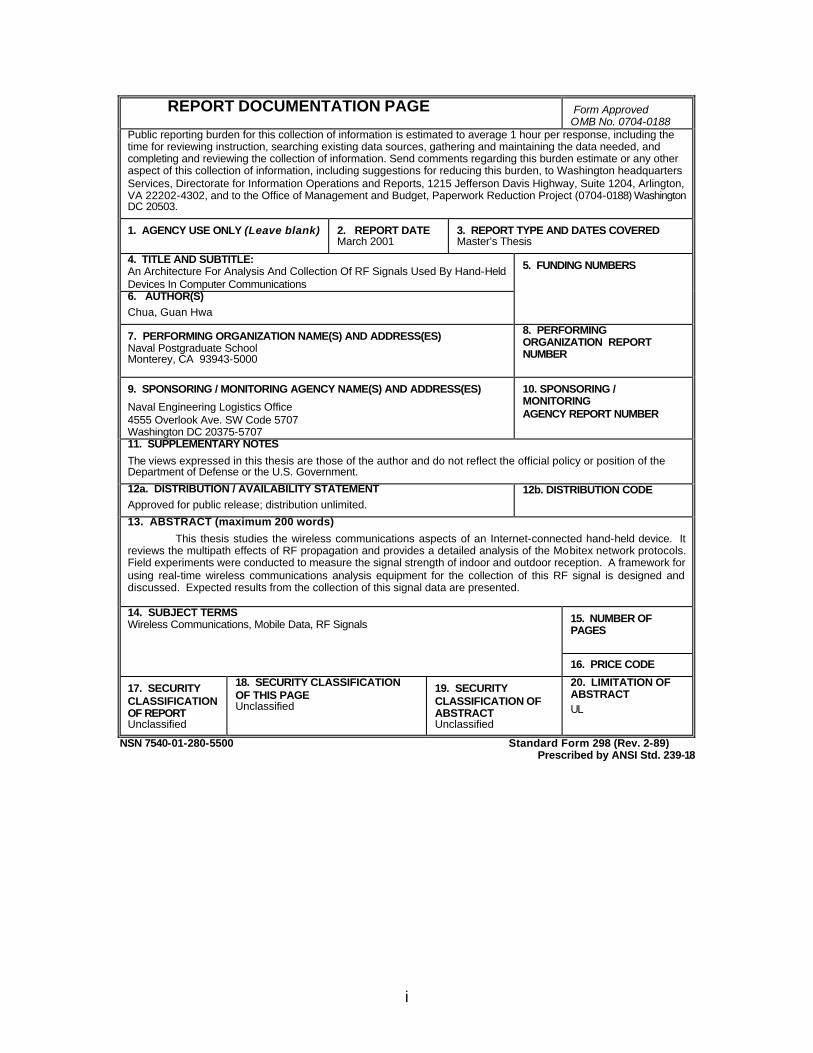
REPORT DOCUMENTATION PAGE Form Approved OMB No. 0704-0188
Public reporting burden for this collection of information is estimated to average 1 hour per response, including the time for reviewing instruction, searching existing data sources, gathering and maintaining the data needed, and completing and reviewing the collection of information. Send comments regarding this burden estimate or any other aspect of this collection of information, including suggestions for reducing this burden, to Washington headquarters Services, Directorate for Information Operations and Reports, 1215 Jefferson Davis Highway, Suite 1204, Arlington, VA 22202-4302, and to the Office of Management and Budget, Paperwork Reduction Project (0704-0188) Washington DC 20503.
1. AGENCY USE ONLY (Leave blank)
2. REPORT DATE March 2001
3. REPORT TYPE AND DATES COVERED Master’s Thesis
4. TITLE AND SUBTITLE: An Architecture For Analysis And Collection Of RF Signals Used By Hand-Held Devices In Computer Communications
5. FUNDING NUMBERS
6. AUTHOR(S) Chua, Guan Hwa
7. PERFORMING ORGANIZATION NAME(S) AND ADDRESS(ES) Naval Postgraduate School Monterey, CA 93943-5000
8. PERFORMING ORGANIZATION REPORT NUMBER
9. SPONSORING / MONITORING AGENCY NAME(S) AND ADDRESS(ES)
Naval Engineering Logistics Office 4555 Overlook Ave. SW Code 5707 Washington DC 20375-5707
10. SPONSORING / MONITORING AGENCY REPORT NUMBER
11. SUPPLEMENTARY NOTES The views expressed in this thesis are those of the author and do not reflect the official policy or position of the Department of Defense or the U.S. Government. 12a. DISTRIBUTION / AVAILABILITY STATEMENT Approved for public release; distribution unlimited.
12b. DISTRIBUTION CODE
13. ABSTRACT (maximum 200 words)
This thesis studies the wireless communications aspects of an Internet-connected hand-held device. It reviews the multipath effects of RF propagation and provides a detailed analysis of the Mobitex network protocols. Field experiments were conducted to measure the signal strength of indoor and outdoor reception. A framework for using real-time wireless communications analysis equipment for the collection of this RF signal is designed and discussed. Expected results from the collection of this signal data are presented.
14. SUBJECT TERMS Wireless Communications, Mobile Data, RF Signals 15. NUMBER OF
PAGES
16. PRICE CODE
17. SECURITY CLASSIFICATION OF REPORT Unclassified
18. SECURITY CLASSIFICATION OF THIS PAGE Unclassified
19. SECURITY CLASSIFICATION OF ABSTRACT Unclassified
20. LIMITATION OF ABSTRACT UL
NSN 7540-01-280-5500 Standard Form 298 (Rev. 2-89) Prescribed by ANSI Std. 239-18

ii
THIS PAGE INTENTIONALLY LEFT BLANK
iii
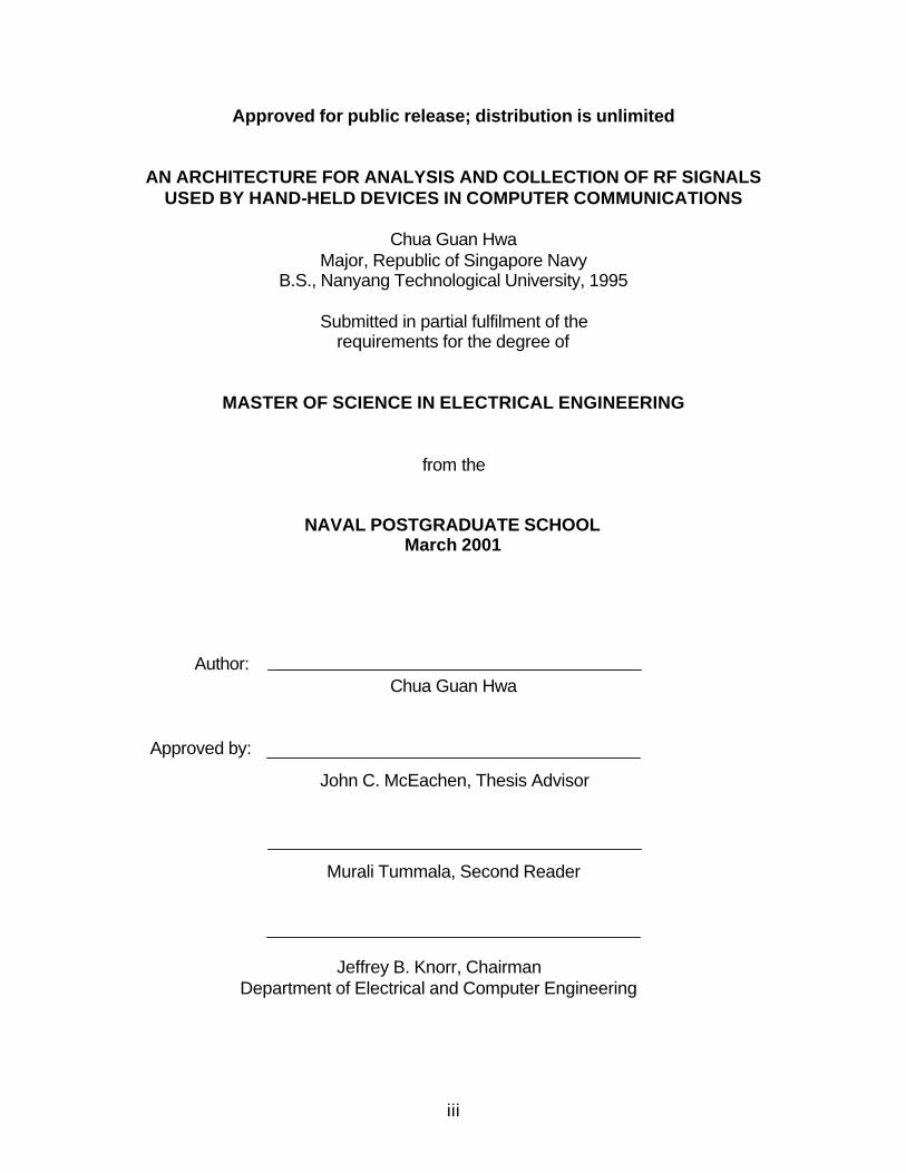
Approved for public release; distribution is unlimited
AN ARCHITECTURE FOR ANALYSIS AND COLLECTION OF RF SIGNALS USED BY HAND-HELD DEVICES IN COMPUTER COMMUNICATIONS
Chua Guan Hwa
Major, Republic of Singapore Navy B.S., Nanyang Technological University, 1995
Submitted in partial fulfilment of the
requirements for the degree of
MASTER OF SCIENCE IN ELECTRICAL ENGINEERING
from the
NAVAL POSTGRADUATE SCHOOL March 2001
Author:
Approved by:
Jeffrey B. Knorr, Chairman Department of Electrical and Computer Engineering
Murali Tummala, Second Reader
John C. McEachen, Thesis Advisor
Chua Guan Hwa

iv
THIS PAGE INTENTIONALLY LEFT BLANK
v
ABSTRACT
This thesis studies the wireless communications aspects of an Internet-
connected hand-held device. It reviews the multipath effects of RF propagation
and provides a detailed analysis of the Mobitex network protocols. Field
experiments were conducted to measure the signal strength of indoor and
outdoor reception. A framework for using real-time wireless communications
analysis equipment for the collection of this RF signal is designed and discussed.
Expected results from the collection of this signal data are presented.

vi
THIS PAGE INTENTIONALLY LEFT BLANK
vii
TABLE OF CONTENTS
I. INTRODUCTION..................................................................................................1 A. BACKGROUND ........................................................................................1
1. Wireless Terminal Features.........................................................2 2. Access to Large Data Bases .......................................................3 3. Information On-Demand...............................................................4 4. Data Entry Medium .......................................................................4 5. Distributed Computing Environment ..........................................5 6. Wireless Terminal Design............................................................6 7. Implementing Wireless Terminals ..............................................9
a. Power Considerations........................................................9 b. Chip Design .......................................................................10 c. RF Transceiver..................................................................11
8. Mobile Packet Data Technology ...............................................11 a. Highlights of a Wireless Network ...................................12 b. Wireless Network Features .............................................12 c. Wireless Data Applications..............................................14
B. OBJECTIVE.............................................................................................15 C. THESIS ORGANIZATION.....................................................................15
II. WIRELESS TERMINAL RADIO PROPAGATION ........................................17 A. INTRODUCTION ....................................................................................17 B. ENVELOPE FADING .............................................................................19 C. DOPPLER SPREAD..............................................................................22 D. TIME-DELAY SPREAD.........................................................................24 E. PROPAGATION CHARACTERISTIC .................................................25
1. Free Space Propagation Loss Equation..................................26 2. Path Loss of NLOS and LOS ....................................................27
F. DIGITAL MODULATION AND DEMODULATIONS ..........................28 G. SUMMARY..............................................................................................31
III. PALM VII COMMUNICATIONS SYSTEM ARCHITECTURE .....................33 A. INTRODUCTION ....................................................................................33 B. SUBSCRIPTIONS ..................................................................................36 C. CHANNEL ACCESS..............................................................................38 D. ROAMING................................................................................................41 E. PALM VII (MOBITEX) PROTOCOL LAYERS ....................................47
1. Network Layers............................................................................48 a. PSUBCOM-Class Packets..............................................49 b. PSOSCOM-Class Packets..............................................49 c. CSUBCOM -Class Packets..............................................49
viii
d. DTESERV-Class Packets ...............................................49 2. Palm VII (Mobitex) Packets .......................................................50
a. Sender and Addressee Field ..........................................51 b. Traffic State Flags.............................................................51 c. Subscription Flags ............................................................51 d. Packet Class and Packet Type.......................................52
3. Data Link Layer ...........................................................................52 4. Physical Layer .............................................................................55
a. Physical Layer Frame Structure .....................................55 b. Other Functions of the Physical Layer ..........................57 c. Mobitex Packets................................................................58
F. SUMMARY...............................................................................................60
IV. EQUIPMENT FOR SIGNAL COLLECTION AND ANALYSIS.....................61 A. TEST EQUIPMENT................................................................................61
1. Spectrum Analyzers....................................................................61 a. Conventional Spectrum Analyzers.................................62 b. Real-Time Spectrum Analyzer........................................63
2. PRACTICAL RESULTS .............................................................66 B. FREQUENCY EVENT TRIGGER........................................................67 C. REAL-TIME WIRELESS COMMUNICATION ANALYZERS ...........68 D. ACCESSORIES......................................................................................70
1. Antenna.........................................................................................70 2. Adjustable Tripod ........................................................................70 3. Low loss Coaxial Cable ..............................................................70
E. EQUIPMENT SET-UP ...........................................................................71 F. PRICE AND AVAILABILITY..................................................................73 G. SUMMARY..............................................................................................73
V. PALM VII SIGNAL ANALYSIS AND SYSTEM DESIGN..............................75 A. SIGNAL STRENGTH RECEPTION ON PALM VII............................75
1. Indoor Experiments.....................................................................76 2. Outdoor Experiments..................................................................77
B. PALM VII’S SIGNAL CHARACTERISTIC...........................................78 1. Intercepted Palm VII’s Signal ....................................................80 2. Palm VII’s Spectrogram .............................................................81 3. Phase Constellations of GMSK Signal ....................................82 4. Palm VII’s Frame Analysis.........................................................83
VI. CONCLUSIONS AND RECOMMENDATIONS .............................................85 A. CONCLUSIONS......................................................................................85 B. RECOMMENDATIONS .........................................................................87
LIST OF REFERENCES...............................................................................................89
INITIAL DISTRIBUTION LIST......................................................................................91

ix
ix
LIST OF FIGURES
Figure I-1. Wireless PDA System Overview. (From Ref. [1]) ................................ 3 Figure I-2. Web-Clipping verse Web Browsing. (From Ref. [1]) ............................ 6 Figure I-3. Front Diagram of a Wireless Terminal. (From Ref. [3])........................ 7 Figure I-4. Back Diagram of a Wireless Terminal. (From Ref. [3]) ........................ 7 Figure II-1. Multipath Fading, Shadowing, and Path Loss Phenomena. ............. 19 Figure II-2. Fading - Illustration of a Time Variable Envelope Faded Channel....22 Figure II-3. Propagation Environment of a Wireless LOS and NLOS Radio
System. .......................................................................................................24 Figure II-4. MSK Signal Generator. (After Ref. [12]) ........................................... 31 Figure III-1 Mobitex Network Architecture. (From Ref. [4]) .................................33 Figure III-2. Mobitex Store-and-Forward Capabilities. ........................................36 Figure III-3 (a) & (b). Channel Access Timing..................................................... 40 Figure III-4. Type 1 SWEEP Frame Format. .......................................................43 Figure III-5. Neighbor Channel Monitoring Inside a Sweep Cycle. ..................... 45 Figure III-6. The Roaming Signal on a System Channel.....................................46 Figure III-7. Mobitex Protocol Layers. .................................................................47 Figure III-8. MPAK Structure...............................................................................50 Figure III-9. Mobitex Frame Structures................................................................ 53 Figure III-10. Coding and Interleaving of a Data Link Block Structure. ............... 58 Figure IV-1. Simplified Concept of a Swept Spectrum Analyzer, with Signal A and
B shown Arriving at the RF In, and Only Signal A Appearing at the Output.63 Figure IV-2. Sweep of a Conventional Spectrum Analyzer. ................................ 63 Figure IV-3. Simplified Conceptual Block Diagram of Real Time Spectrum
Analyzer, with Signal A and B shown Arriving at the RF In, and Both Signals Appear at the Output. ..................................................................................64
Figure IV-4. Simultaneous Acquisition of Signal A and B. ..................................64 Figure IV-5. Frame Acquisition. ..........................................................................65 Figure IV-6. RTSA Architecture, Showing Frequency and Time Memories. .......66 Figure IV-7. CDMA Mobile Phone RF Signal. ..................................................... 67 Figure IV-8. Frequency Event Trigger................................................................. 68 Figure IV-9. Palm VII’s Antenna..........................................................................71 Figure IV-10. Equipment Setup for the RF Signal Collections. ...........................72 Figure V-1. WCA380 Screen Shot of a Pseudo-random Palm VII RF Signal. ....79 Figure V-2. GMSK Signal used by Palm VII. ...................................................... 80 Figure V-3. Palm VII’s Spectrogram ...................................................................81 Figure V-4. Phase Constellation of GMSK Signal...............................................82 Figure V-5. Palm’s Frame.................................................................................. 83

x
THIS PAGE INTENTIONALLY LEFT BLANK
xi
LIST OF TABLES Table 1. Setup Quotes for WCA 330/380..................................................................74 Table 2. Table Shown on Palm VII Diagnostic Screen. ...........................................76 Table 3. Indoors Signal Strength Reception..............................................................77 Table 4. Outdoor Signal Strength Reception. ............................................................78

xii
THIS PAGE INTENTIONALLY LEFT BLANK
xiii
ACKNOWLEDGEMENTS
First, I am thankful to MINDEF and the SAF for giving me this opportunity to pursue a postgraduate degree at Naval Postgraduate School.
Professor John C. McEachen, thesis advisor, and Professor Murali
Tummala, second reader, gave good suggestions and provided me with insights on computer communications.
Friends and colleagues gave encouragement, which permitted continuous
progress and completion of this thesis.
Finally, I am extremely thankful for the support given by my wife, Li Li, who worked tirelessly, often late into the evenings, bringing up our two kids, daughter, Xyn Yee, and son, Yoong Joo, and for all of us to be comfortable while I worked on this thesis. Without her support this thesis would not have succeeded.

xiv
THIS PAGE INTENTIONALLY LEFT BLANK
xv
EXECUTIVE SUMMARY A framework for the collection of Palm VII RF (Radio Frequency) signals has been presented in response to the search for an advanced mobile data communications device. Field experiments of signal strength in the 900 MHz frequency range for indoor and outdoor environments at NPS (Naval Postgraduate School) were conducted. A specific system setup for real-time wireless communication signal analysis using a spectrum analyzer was proposed. Expected results, in the form of the real-time spectrum analyzer screen shots, were presented. Four graphical displays showing the spectrum of the intercepted GMSK (Gaussian Minimum Shift Keying) signal, the spectrogram, the phase constellations and the frame structure were presented and discussed. Multipath effects of RF signal propagation were reviewed. RF propagation loss for NLOS (Non-Line-of-Sight) and LOS (Line-of-Sight) were analyzed. Signal strength measurements using the Palm VII Diagnostic function confirmed this fading and loss, contrasting indoor signals with outdoor signals. Experimental results showed satisfactory indoor signal strength values within Spanagel Hall, NPS. The average reception quality (as recorded by Palm VII) was approximately 67.33%. With this received signal strength, wireless communications using Palm VII provided little distortion. It is also confirmed that outdoor reception was better than that of the indoors, with an average reception quality of 78.9% across the NPS campus; for comparison, an average reception quality of 92% has been recorded in some metropolitan areas.
This work also analyzed the Mobitex system architecture used in Palm VII wireless communication network. Supporting a data rate of 8 kbps, this cellular-based network utilizes a hierarchical structure that may contain up to six levels of network nodes. The infrastructure is comprised of three types of nodes: a base station, local switches, and regional switches. The cells served by the same local switch form a service area or subnets. In each service area, 10 to 30 frequency channels are allocated to radio service. Each base station utilizes one to four channels that have a 12.5 kHz bandwidth. The allocated RF spectrums are 935 to 940 MHz for the downlink (base station to mobile) and 896 to 901 MHz for the uplink (mobile to base station). The base stations are connected to local switches via local telephone facilities using either an X.25 or HDLC (High-level Data Link Control) data link. Additionally, this thesis highlighted the subscription features, roaming functions and the reserved slotted ALOHA channel access of the Palm VII wireless system. The Palm VII wireless communications protocol layers are analyzed and discussed in details. A brief comparison of Mobitex and CDPD (Cellular Digital Packet Data) is also provided. In summary, this analysis of a state-of-the-art wireless Internet hand-held devices provided a useful background for investigation of an effective and efficient wireless communications system in tactical environments.
1
I. INTRODUCTION
This thesis is part of an effort by the Department of Electrical and
Computer (ECE) Engineering to study the communications protocols and
mechanisms of a technologically advanced wireless handheld Internet-connected
device. The main contributions of this thesis are an analysis of the operations of
this device and the design of a framework to capture the RF transmission signals
to and from such a wireless terminal.
The bursty nature of modern digital mobile communication methods
impose ever increasing demands for which conventional test equipment
becomes inadequate. An optimum system setup to intercept these wireless data
transmissions is proposed using the Real Time Spectrum Analyzer (RTSA). The
RTSA is a sophisticated instrument, which has the ability to seamlessly capture
these signals, and performs enhanced measurements in the time, frequency, and
modulation domains. This study will allow the DoD agencies to analyze the
performance and security aspects associated with this form of computer
communications.
A. BACKGROUND
The personal communications industry has seen explosive growth in the
past several years, especially in the number and types of services and
technologies. In voice band communications, systems such as cellular
telephones, radio pagers, and cordless telephones have become commonplace.
In computing, portable laptops computers are boasting capabilities far in excess
of the desktop machines of only few years ago, and multi-MIPS (millions-
2
instructions-per-second), RISC-based (reduce-instruction-set-computer) portable
PDAs (personal digital assistants) are available. Despite the myriad of
technologies to be had, however, little integration of these diverse services – the
combination of computation and data communication facilities in a portable unit –
has occurred. One unit, a specialized wireless PDA, has shown remarkable and
seamless integration of services to provide ubiquitous access to data
computation and communication, via the Internet. This unit is built by Palm
Computing, Inc, which has two of the VII series models that provide mobile
wireless communications and access to the Internet – the Palm VII and the Palm
VIIx models.
1. Wireless Terminal Features
The mobile unit or wireless terminal typically is in full duplex
communication with a network base station, which serves as a gateway between
the wired and wireless media. Users access services over a high-speed
communications backbone via the base station, including communicating with
another person, who is also tied into the network. This idea can also be
extended to a user communicating not only with another person, but also with
network “servers”. Because the data bandwidth of present and future fibre optic
networks is easily in excess of 10 Gb/s, these centralized servers can provide a
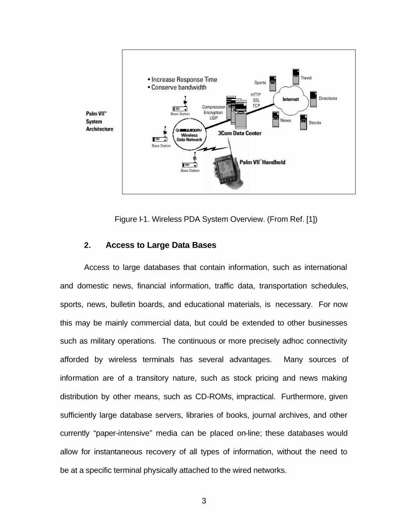
wide variety of information services to users. A schematic view of such a system
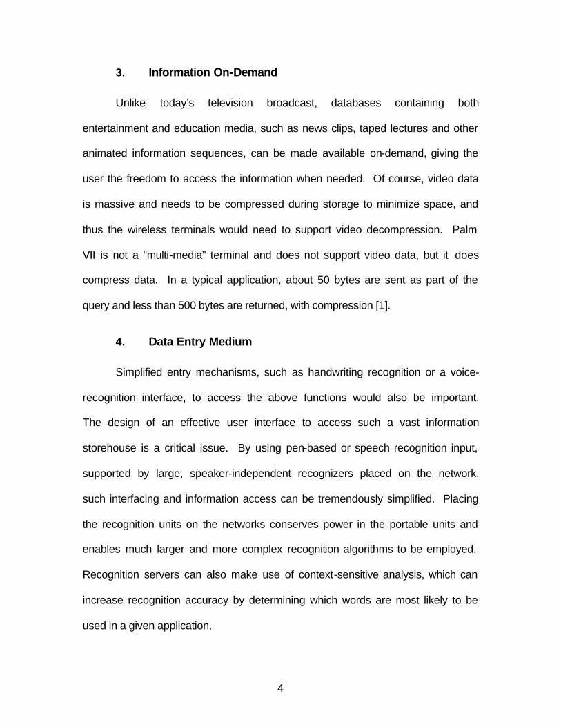
is shown in Fig. I-1. Four of the main features of a wireless terminal are
discussed in the following sections.
3
Figure I-1. Wireless PDA System Overview. (From Ref. [1])
2. Access to Large Data Bases
Access to large databases that contain information, such as international
and domestic news, financial information, traffic data, transportation schedules,
sports, news, bulletin boards, and educational materials, is necessary. For now
this may be mainly commercial data, but could be extended to other businesses
such as military operations. The continuous or more precisely adhoc connectivity
afforded by wireless terminals has several advantages. Many sources of
information are of a transitory nature, such as stock pricing and news making
distribution by other means, such as CD-ROMs, impractical. Furthermore, given
sufficiently large database servers, libraries of books, journal archives, and other
currently “paper-intensive” media can be placed on-line; these databases would
allow for instantaneous recovery of all types of information, without the need to
be at a specific terminal physically attached to the wired networks.
4
3. Information On-Demand
Unlike today’s television broadcast, databases containing both
entertainment and education media, such as news clips, taped lectures and other
animated information sequences, can be made available on-demand, giving the
user the freedom to access the information when needed. Of course, video data
is massive and needs to be compressed during storage to minimize space, and
thus the wireless terminals would need to support video decompression. Palm
VII is not a “multi-media” terminal and does not support video data, but it does
compress data. In a typical application, about 50 bytes are sent as part of the
query and less than 500 bytes are returned, with compression [1].
4. Data Entry Medium
Simplified entry mechanisms, such as handwriting recognition or a voice-
recognition interface, to access the above functions would also be important.
The design of an effective user interface to access such a vast information
storehouse is a critical issue. By using pen-based or speech recognition input,
supported by large, speaker-independent recognizers placed on the network,
such interfacing and information access can be tremendously simplified. Placing
the recognition units on the networks conserves power in the portable units and
enables much larger and more complex recognition algorithms to be employed.
Recognition servers can also make use of context-sensitive analysis, which can
increase recognition accuracy by determining which words are most likely to be
used in a given application.
5
5. Distributed Computing Environment
The system would provide support for a distributed computing
environment, such as MIT’s X-Window system. In distributed computing
environments, computation need not take place on a local machine; instead,
computation is performed by programs executing on one or more remote
machines. The user’s terminal may have no computing capability except that
required to act as an intelligent display device. Many such inexpensive “X-
terminals” already exist. X-terminals possess all of the necessary networking
capability to communicate with as many remote servers as needed. As
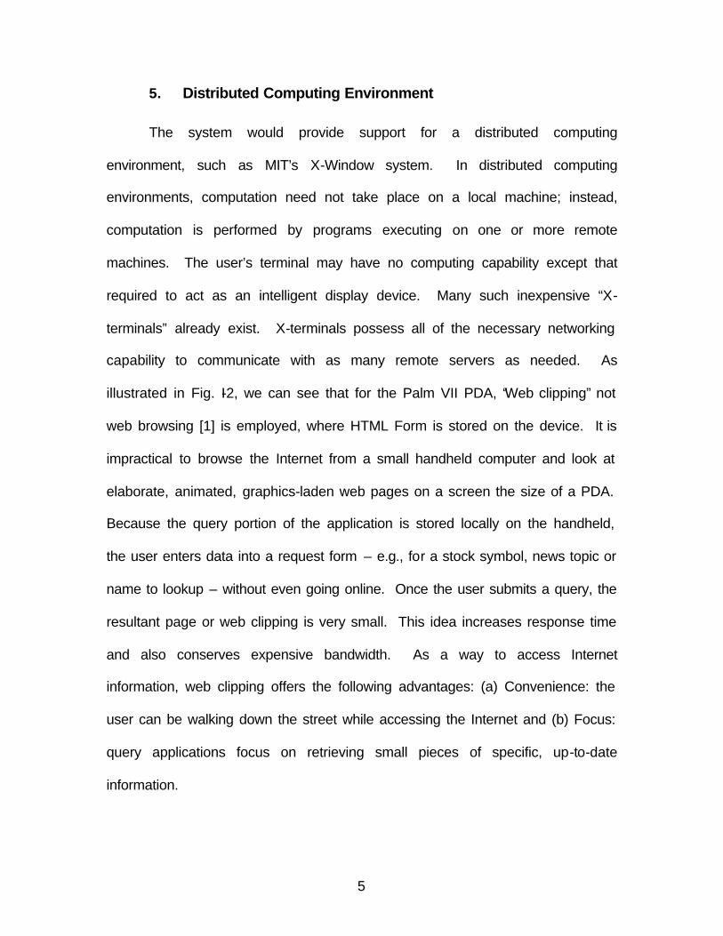
illustrated in Fig. I-2, we can see that for the Palm VII PDA, “Web clipping” not
web browsing [1] is employed, where HTML Form is stored on the device. It is
impractical to browse the Internet from a small handheld computer and look at
elaborate, animated, graphics-laden web pages on a screen the size of a PDA.
Because the query portion of the application is stored locally on the handheld,
the user enters data into a request form – e.g., for a stock symbol, news topic or
name to lookup – without even going online. Once the user submits a query, the
resultant page or web clipping is very small. This idea increases response time
and also conserves expensive bandwidth. As a way to access Internet
information, web clipping offers the following advantages: (a) Convenience: the
user can be walking down the street while accessing the Internet and (b) Focus:
query applications focus on retrieving small pieces of specific, up-to-date
information.
6
Figure I-2. Web-Clipping verse Web Browsing. (From Ref. [1])
6. Wireless Terminal Design
Clearly, the cornerstone of the entire system lies in the ability of wireless
communications links to support all of the aforementioned services.
Correspondingly, it is this desire for portability that translates directly into design
constraints on the size and weight of the terminals, the power they consume, and
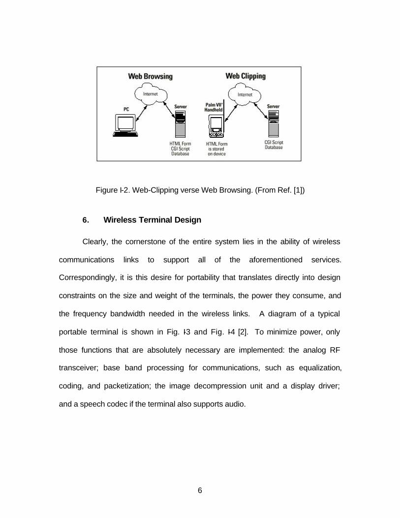
the frequency bandwidth needed in the wireless links. A diagram of a typical
portable terminal is shown in Fig. I-3 and Fig. I-4 [2]. To minimize power, only
those functions that are absolutely necessary are implemented: the analog RF
transceiver; base band processing for communications, such as equalization,
coding, and packetization; the image decompression unit and a display driver;
and a speech codec if the terminal also supports audio.
7
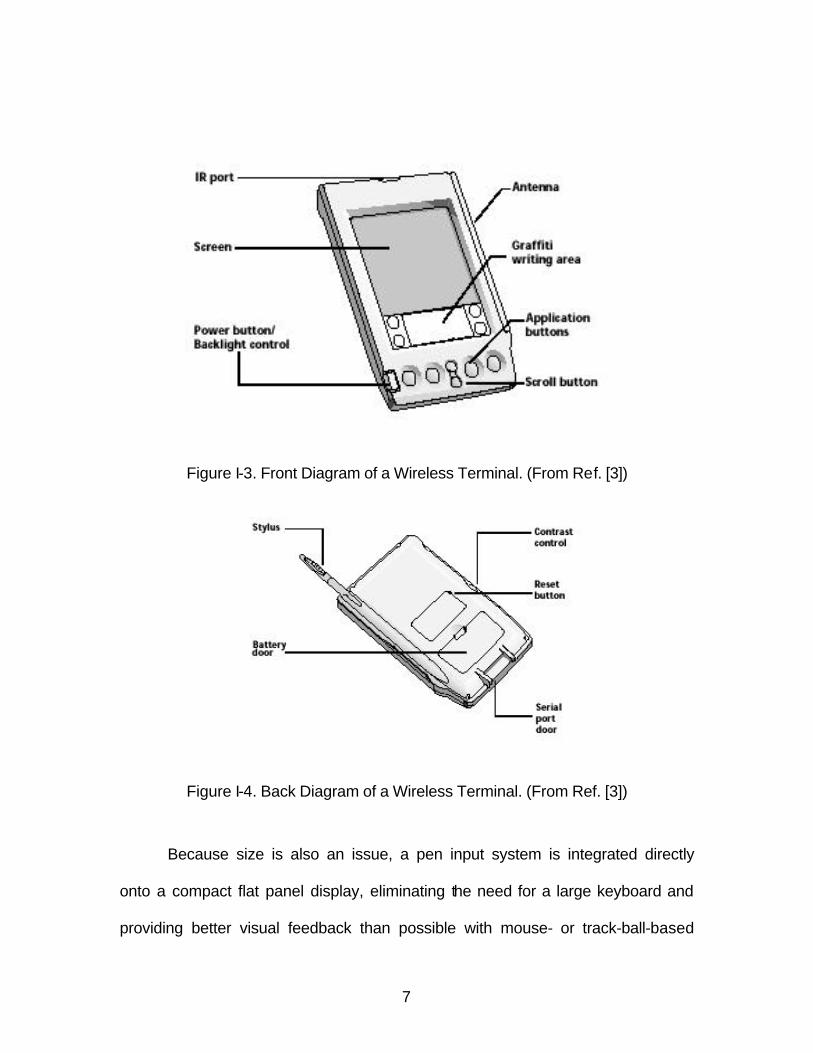
Figure I-3. Front Diagram of a Wireless Terminal. (From Ref. [3])
Figure I-4. Back Diagram of a Wireless Terminal. (From Ref. [3])
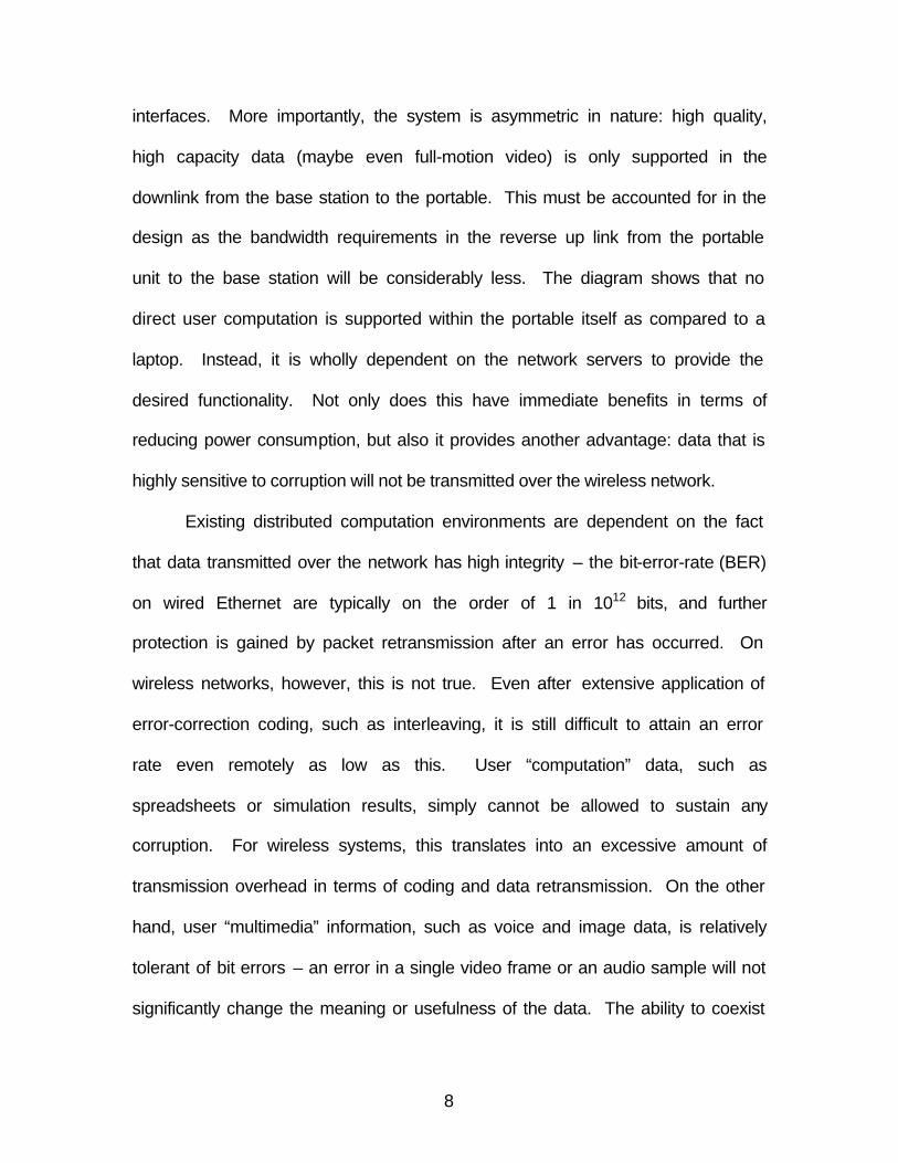
Because size is also an issue, a pen input system is integrated directly
onto a compact flat panel display, eliminating the need for a large keyboard and
providing better visual feedback than possible with mouse- or track-ball-based
8
interfaces. More importantly, the system is asymmetric in nature: high quality,
high capacity data (maybe even full-motion video) is only supported in the
downlink from the base station to the portable. This must be accounted for in the
design as the bandwidth requirements in the reverse up link from the portable
unit to the base station will be considerably less. The diagram shows that no
direct user computation is supported within the portable itself as compared to a
laptop. Instead, it is wholly dependent on the network servers to provide the
desired functionality. Not only does this have immediate benefits in terms of
reducing power consumption, but also it provides another advantage: data that is
highly sensitive to corruption will not be transmitted over the wireless network.
Existing distributed computation environments are dependent on the fact
that data transmitted over the network has high integrity – the bit-error-rate (BER)
on wired Ethernet are typically on the order of 1 in 1012 bits, and further
protection is gained by packet retransmission after an error has occurred. On
wireless networks, however, this is not true. Even after extensive application of
error-correction coding, such as interleaving, it is still difficult to attain an error
rate even remotely as low as this. User “computation” data, such as
spreadsheets or simulation results, simply cannot be allowed to sustain any
corruption. For wireless systems, this translates into an excessive amount of
transmission overhead in terms of coding and data retransmission. On the other
hand, user “multimedia” information, such as voice and image data, is relatively
tolerant of bit errors – an error in a single video frame or an audio sample will not
significantly change the meaning or usefulness of the data. The ability to coexist
9
with an error-prone transmission environment has tremendous impact on the
overall system design. Thus, the portable unit described above is truly a terminal
dedicated to wireless PDA functions, not simply a laptop computer with a
wireless LAN/modem attached to it.
7. Implementing Wireless Terminals
Incoming data to a portable can be of three types: digital video, screen
graphics, or pen input. Out-going data can be either pen or voice input. The
asymmetry in the data rates of the uplink and the downlink is clear – no high bit
rate signals are intended for transmission from the mobile to the base station.
The hardware design must also reflect this asymmetry: within the analog RF
block, the receiver design becomes critical because it must demodulate a high bit
rate signal corrupted by noise and distortion. On the other hand, the transmitter
is relatively simple with low data rate and output power requirements.
a. Power Considerations
One key consideration is how long the portable can function
between battery recharging. Ideally, it should be able to operate for one workday
or eight to ten hours of battery life. Thus, power minimization becomes a serious
concern. The largest power consumer in current portables is the backlighting of
flat panel displays. This issue is even more significant if there is color content.
As display technologies improve screen contrast, however, this requirement will
be significantly relaxed, implying low-power techniques for implementing the
analog and digital circuitry are needed.
10
For Palm VII, there is backlighting (for viewing in dark conditions) for the
black-and-white LCD display. It requires two AAA size batteries which can last
for almost 3 weeks of normal use.
b. Chip Design
Semiconductors are the driving force behind virtually any
electronics device. Powerful microprocessors, such as the Pentium, and digital
signal processors (DSPs) are delivering incredible performance with an
exponential pace of progress in this remarkable industry. With present day
technology – single chip packaging using printed circuit boards for
interconnection – one third or more of the total power is consumed by the chip’s
input/output (I/O) because of the capacitances at the chip boundaries inside the
chip. Typical values range from a few ten’s of femto-farads at internal chip nodes
to ten’s of pico-farads at the chip interfaces attributed to pad capacitances and
board traces. To reduce power consumed in the I/O, low-capacitance, high-
density interconnect methods such as multi-chip module (MCM) technologies,
are employed. MCM integrates many individual chip dies into a single structure,
reducing the size of inter-chip capacitance to the same order-of-magnitude as
on-chip capacitances, and thus minimizing the power consumed in the I/O
drivers. Also, because the packing density has increased and with the ever-
decreasing size of CMOS circuitry (down to 0.18 µm line widths), over 1010
transistors can be placed within a single eight-by-eleven MCM substrate. Area
constraints imposed by available silicon is no longer of great issue, allowing for
greater possibilities in power optimization.
11
The main processor employed in Palm VII is the 32-bit Motorola
DragonballTM integrated portable system processor. The chip yields 5 MIPS
performance at 33 MHz processor clock and features a synthesizable 68000, the
popular Motorola embedded processor.
c. RF Transceiver
For analog RF transceivers, however, there are other design
considerations beyond low power implementation. Due to size considerations,
traditional discrete element design is not feasible for a small, portable unit such
as the Palm VII. Single-chip integration techniques that exploit advances in
silicon CMOS (as opposed to gallium arsenide, GaAs) must be explored to
address cost and manufacturing concerns. Likewise, the fact that digital circuitry
is readily available on-chip also opens up new possibilities: analog performance
requirements can be reduced at the expense of increased digital signal
processing.
Palm VII employs the Texas Instruments TCM series line of
telecommunication applications chips for its transceiver unit.
8. Mobile Packet Data Technology
Mobile data is the most diverse of the wireless communications market
segments. Even when fixed-point wireless terminals and satellite
communications are excluded, mobile data has many dimensions, using various
types of terminals to access anything from one-way store-and-forward
messaging to real-time video over different kinds of networks.
12
a. Highlights of a Wireless Network
Palm VII uses the Mobitex packet-switched mobile data network for
its wireless communications. Two of the more important reasons for selecting
Mobitex were its state-of-the-art technology and its open architecture. The
channel rate was set at 8 kbps, which is significantly faster than other wireless
data networks or most cellular telephone modems. This is able to satisfy users’
demand and yet efficient in its use of spectrum. The base stations are laid out
over a service area in a grid pattern using the same engineering rules as for
cellular telephony relative to interference management, frequency reuse, cell
splitting, etc. In fact, the system is much like a cellular telephone system except
that there is no need for handoff during packet transmissions. When a change
from one base station to a better one is required, that decision is made by the
mobile set, in this case Palm VII hand-held, not the network computer as in a
cellular telephony. Messages are handled at the lowest node in the network that
is common to the origination and destination addresses. This minimizes the
packet delay, enables autonomous operation of nodes in case of failures in other
portions of the network, and allows host connections at the local level which
reduce connection costs.
b. Wireless Network Features
From the customer’s perspective, a Mobitex network can appear to
operate as either a public or a private network. A customer subscribes for
service using one or more mobile terminal subscriptions and one or more fixed
terminal subscriptions, each with an associated subscription number or address.
13
The system can accommodate up to 6 million separate addresses. Alternatively,
the address can be associated with an individual via a personal subscription.
The individual can then log onto the system at any Mobitex terminal and his/her
messages will be addressed to that terminal until he/she logs off. The Mobitex
technology supports user functions such as:
§ Message store-and-forward
§ Mobile tracking
§ Multi-address messages
§ Group broadcasts
§ Automatic roaming
§ Status messages
§ Mobile to mobile connections
§ X.25 and HDLC host connections
Cellular networks or competing packet-switched data networks offer few of
these functions. Mobitex wireless data networks are becoming widely accepted
all over the world. Mobitex technology has become a true de facto standard. In
the Untied States, RAM Mobile Data operates Mobitex systems nationwide in
7700 cities and towns, covering over 92 percent of America’s urban business
population [3], and over 11,000 miles of interstate highway, with automatic
seamless roaming across all service areas. Mobitex networks are installed in 16
countries on five continents, including Canada, the Untied Kingdom, France,
Sweden, Finland, Norway, Belgium, the Netherlands, Singapore and Australia.
14
There is a Mobitex Operators Association1 (MOA) to oversee the specifications,
coordinate software and hardware development, and further evolve technology.
The MOA without any license or fee publishes the specifications; thus, there are
a number of terminal suppliers and equipment developers. The primary reason
that mobile data has managed to withstand the cellular phone network’s
competition so far is the increased performance of data transmission. With the
emerging 3G (Third Generation) technology, the convergence of voice and data
will be the key to future generations of mobile communication which allow
wireless access to broadband fixed networks and seamless roaming among
different systems.
c. Wireless Data Applications
From the user perspective, mobile data systems offer an alternative
that usually guarantees both cheaper and improved services in a wide range of
packet-data applications, such as wireless messaging, remote data collection,
remote database access, wireless credit card verification, automatic vehicle
location, computerized dispatch, and Internet access. All these applications drive
the market of the present mobile data networks. Prospective customers include
DoD, which needs accurate, real-time information. Take a simply case, such as
truck and driver’s status, routing and scheduling, and two-way communications
between the drivers and the dispatchers, a typical example where wireless
applications would be extremely effective. Furthermore, DoD (Navy’s ships
deployed in the ocean) being a heavy user of e-mails, remote data access, and
1 MOA site is located at http://www.mobitex.org/index.html
15
data collection needs a system to connect their mobile workforce to a central
computer without the constraints of a wired telephone connections. Mobile data
networks bring new opportunities to these businesses without excessive cost
requirements.
B. OBJECTIVE
The objective of this thesis is to analyze the communications protocol of
the Palm VII wireless terminal. This includes the studies of the wireless
terminals’ RF characteristics and its modulation, the operational aspects of
mobile data networks, the basic networking layers of a wireless network and its
transmission protocol.
The second objective of this thesis is to investigate for an optimum way to
collect and analyze Palm VII’s RF signals. This includes the exploration of the
required equipment and the setup of the equipment for measuring the Palm VII
RF signals.
C. THESIS ORGANIZATION
The thesis is divided into six chapters. In Chapter I, the background
information on the wireless hand-held device is presented. This includes its
features, design and implementation. In Chapter II, a review of RF propagation
effects including on its multipath, propagation loss and modulation and
demodulation techniques are presented. In Chapter III, the details of the
communication protocol and the system network of Palm VII are discussed. The
equipment for RF signal collection and its analysis are presented in Chapter IV.
It includes the setup, the required interconnection accessories and the cost of
16
these apparati. Field experiments on the RF signal strength for the Palm VII are
described in Chapter V. The expected signal collection using the equipment
setup from the preceding chapter is also discussed in this chapter. The thesis
conclusion and recommendations for future work are in Chapter VI.
17
II. WIRELESS TERMINAL RADIO PROPAGATION
A. INTRODUCTION
Palm VII uses a typical model of a cellular network. Each transmission
link consists of an elevated base station antenna (or multiple antennas) and a
mobile antenna mounted on the transceiver (transmitter/receiver) of a wireless
terminal, such as Palm VII’s built-in antenna. These are linked by a relatively
short distance LOS (line-of-sight) RF propagation path combined with many
NLOS (non-line-of-sight) reflected RF propagation paths. In most applications,
no complete, direct LOS propagation exists between the base station antenna,
also known as the access point, and the mobile antennas because of natural and
man-made obstacles. In such environments the radio transmission path, or radio
link, may be modeled as a randomly varying propagation path. In many
instances, there may exist more than one propagation path. This situation is
referred to as multi-path propagation. The propagation path changes with the
movement of the wireless terminal. A typical scenario is one of an executive
interacting with his PDA (personal digital assistance or Palm VII in this thesis)
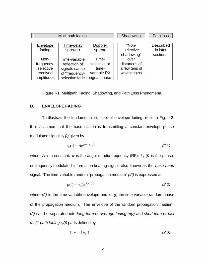
and the movement of the surroundings and environment. Fading or loss of the
signal [5] can be due to three different factors:
• Rayleigh fading – occurs when the terminal is used while in motion.
The higher the speed, the worse the BER becomes.
• Multi-path reflection – some signals arrive directly at the receiver
while others bounce off objects before arriving. Some of the signals
18
follow a longer path and arrive a fraction of a second later. This may
have the effect of reducing the signal amplitude.
• Atmospheric fading – a “null” where communication is difficult.
Moving the wireless terminal 10 cm to 20 cm may be enough to avoid
this problem.
Even the smallest, slowest movement causes time-variable multi-path,
and hence random time-variable signal reception. For example, assume that the
cellular wireless terminal user is sitting in an automobile in a parking lot, near a
busy freeway. Although the user is relatively stationary, part of the environment
is moving at 110 km/h (about 68 mph). The automobiles on the freeway become
“reflectors” of radio signals. If during transmission or reception the user is also
moving (for example, driving at 110 km/h), the randomly reflected signals vary at
a faster rate. The rate of variations of the signal are frequently described as
Doppler spread. Three partially separated effects known as multi-path fading,
shadowing, and path loss characterize radio propagation in such environments.
Multi-path fading is described by its envelope fading (non-frequency-selective
amplitude fluctuations), Doppler spread (time-selective or time-variable random
phase noise), and time-delay spread (variable propagation distance of reflected
signals causing time variations in the reflected signals). These fading are
summarized in Fig. II-1.
19
Multi-path fading Shadowing Path loss
Envelope fading
Non-
frequency-selective received
amplitudes
Time-delay spread τ
Time-variable reflection of
signals cause of “frequency-selective fade
Doppler spread
Time-
selective or time-
variable RX signal phase
“Non-selective
shadowing” over
distances of a few tens of wavelengths
Described in later
sections.
Figure II-1. Multipath Fading, Shadowing, and Path Loss Phenomena.
B. ENVELOPE FADING
To illustrate the fundamental concept of envelope fading, refer to Fig. II-2.
It is assumed that the base station is transmitting a constant-envelope phase
modulated signal sT (t) given by
))(()( ttjT
sAets φω += (2.1)
where A is a constant, ω is the angular radio frequency (RF), φs (t) is the phase-
or frequency-modulated information-bearing signal, also known as the base-band
signal. The time-variable random “propagation medium” p(t) is expressed as
))(()()( tj retrtp ω= (2.2)
where r(t) is the time-variable envelope and ωr (t) the time-variable random phase
of the propagation medium. The envelope of the random propagation medium
r(t) can be separated into long-term or average fading m(t) and short-term or fast
multi-path fading ro(t) parts defined by
)()()( trtmtr o= (2.3)
20
where ro(t) has unit mean value.
If the base station and the wireless terminal are both stationary but the
environment is moving (this is almost always the practical case, since even the
smallest or slowest movement causes time-variable random reflections in an
NLOS system), then we use equation 2.3 with time t as the random variable. If
the wireless terminal is moving at a speed of ν m/s, then the propagation
distance χ between the base station and terminal path is given by
tνχ = (2.4)
In this case, we can write equation 2.3 as
)()()( χχχ ormr = (2.5)
The constant envelope, transmitted signal sT (t) is multiplied by the time-variable
random “transfer function” of the propagation medium p(t). Thus, we have a
multiplicative fade model. Note that we use additive models such as the additive
white Gaussian noise (AWGN) model used in stationary channels, as
encountered in geo-stationary satellite and coaxial cable systems.
The received signal at the wireless terminal, sR (t), is given by
)]()([
)())((
)()]([
)()(
)()(
)(
)()(
tttjo
tjo
ttj
tjttj
TR
rs
rs
rs
etrtAm
etrtmAe
etrAe
tptss
φφω
φφω
φφω
++
+
+
=
=
=
=
(2.6)
Recall that the transmitted signal, sT(t), is a constant-envelope (A = constant)
phase-modulated signal having a phase modulation give by φT (t). The received
21
signal, sR(t), has an envelope given by r(t) = m(t)ro(t) (long term “average”
component m(t) multiplied by a short-term, fast fading component ro(t)). A time-
variable random-phase modulation component φr (t) has been introduced by the
wireless propagation medium. The speed variation of φr (t) is dependent on the
speed of the wireless terminal and the changes in the propagation medium, for
example, the relative speed of two automobiles travelling in opposite directions.
The φr (t) random-phase variation is the cause of frequency spreading (recall
phase-modulation correspondence with frequency modulation), also known as
Doppler spread.
When the receiver, the transmitter, or the surroundings are moving, even
slightly, the effective movement may exceed a few hundreds of wavelength. For
example, in a 900 MHz radio system the wavelength “λ” is
λ = c / f = 3(10)8 / 9(10)8 = 33.3 cm (or 13.1 inches).
Thus, if the receiver is moving over a range of only 3.3 cm (or 1.3 inches), it
moves a ratio of 3.3:33 = 0.1 or more than 10 hundredths of a wavelength.
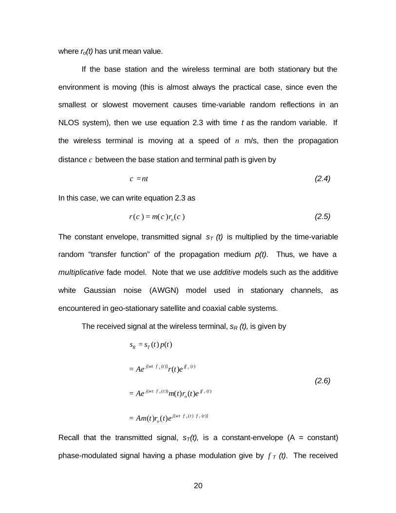
Movement greater than a few hundredths of wavelength could lead to signal
envelope fluctuations. This is illustrated in Fig. II-2.
22
sT(t) sO(t)
Figure II-2. Fading - Illustration of a Time Variable Envelope Faded Channel.
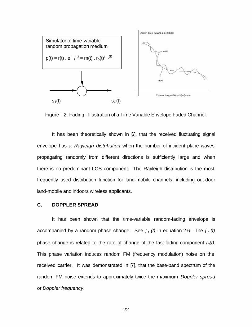
It has been theoretically shown in [6], that the received fluctuating signal
envelope has a Rayleigh distribution when the number of incident plane waves
propagating randomly from different directions is sufficiently large and when
there is no predominant LOS component. The Rayleigh distribution is the most
frequently used distribution function for land-mobile channels, including out-door
land-mobile and indoors wireless applicants.
C. DOPPLER SPREAD
It has been shown that the time-variable random-fading envelope is
accompanied by a random phase change. See φr (t) in equation 2.6. The φr (t)
phase change is related to the rate of change of the fast-fading component ro(t).
This phase variation induces random FM (frequency modulation) noise on the
received carrier. It was demonstrated in [7], that the base-band spectrum of the
random FM noise extends to approximately twice the maximum Doppler spread
or Doppler frequency.
Simulator of time-variable random propagation medium p(t) = r(t) . ej∅
r(t) = m(t) . ro(t)j∅
r(t)
23
The maximum Doppler frequency, ƒd, is given by
ƒd = υ / λ (2.7)
and λ= c / ƒ (2.8)
Thus
ƒd = ν ⁄ λ = ν ⁄ (c ⁄ ƒ) = νƒ ⁄ c (2.9)
where c = 3(10)8 m/s, the velocity of light, and ν is the speed of the vehicle,
including the speed of the mobile environment, in meters per second. λ is the
wavelength of the radio signal in meters and ƒ is the radio frequency.
Doppler spread is defined as the spectral width of a received carrier when
a single sinusoidal carrier is transmitted through the multi-path channel. If a
carrier wave (an unmodulated sinusoidal tone) having a radio frequency ƒc is
transmitted, then because of Doppler spread, ƒd , we receive a smeared signal
spectrum with spectral components between ƒc - ƒd and ƒc + ƒd. This effect may
be interpreted as a temporal de-correlation effect of the random multi-path-faded
channel and is known as time-selective fading.
Coherence time (CT) is usually defined as the required time interval to
obtain an envelope correlation of 0.9 or less. It is inversely proportional to the
maximum Doppler frequency and is defined as
CT = 1 / ƒd (2.10)
24
D. TIME-DELAY SPREAD
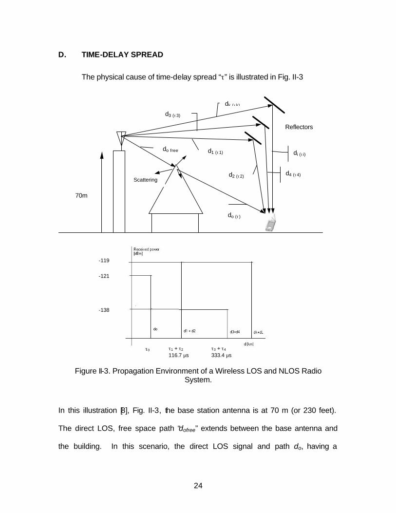
The physical cause of time-delay spread “τ” is illustrated in Fig. II-3
Figure II-3. Propagation Environment of a Wireless LOS and NLOS Radio System.
In this illustration [8], Fig. II-3, the base station antenna is at 70 m (or 230 feet).
The direct LOS, free space path “dofree” extends between the base antenna and
the building. In this scenario, the direct LOS signal and path do, having a
do free
do (τ )
Scattering
d1 (τ1)
d2 (τ2)
d3 (τ3)
d4 (τ4)
dk (τk)
Reflectors
70m
-119
-121
-138
τ0 τ1 + τ2 116.7 µs
τ3 + τ4 333.4 µs
di (τ i)
25
propagation time τ, is severely attenuated by a high-rise building. Assume that
the attenuated LOS signal power is –121 dBm. The wireless terminal also
receives reflected signals through the d1 + d2 path, d3 + d4 path and dk + di path,
and large number of other reflected signal paths. If it is assumed that the
strength of the signal received through the path with total distance d1 + d2 = -119
dBm, then we have an approximately equal direct strength (attenuated LOS) and
reflected LOS pattern. In this illustrative example, if d1 + d2 = 36 km (or 22 miles)
and d0 = 1 km (or 0.6 miles), there is a path delay or delay spread of
τ = ( d1 + d2 – d0) / c = 116.7 µs
The RMS value of Delay spread is among the most frequently used practical
system specifications.
The effect of time-delay spread can also be interpreted as a frequency-
selective fading effect. This effect may cause severe waveform distortions in the
demodulated signal and may impose a limit on the BER (bit-error-ratio)
performance of high-speed digital radio systems.
Coherence bandwidth (CB) is the frequency spacing required for an
envelope correlation of 0.9 or less. This bandwidth is inversely proportional to
the rms value of time-delay spread, defined by
CB = 1 / τrms (2.11)
E. PROPAGATION CHARACTERISTIC
In this section the following propagation path loss characteristics of LOS
and NLOS systems are discussed: free space equations, path loss models, and
the empirical path loss formula.
26
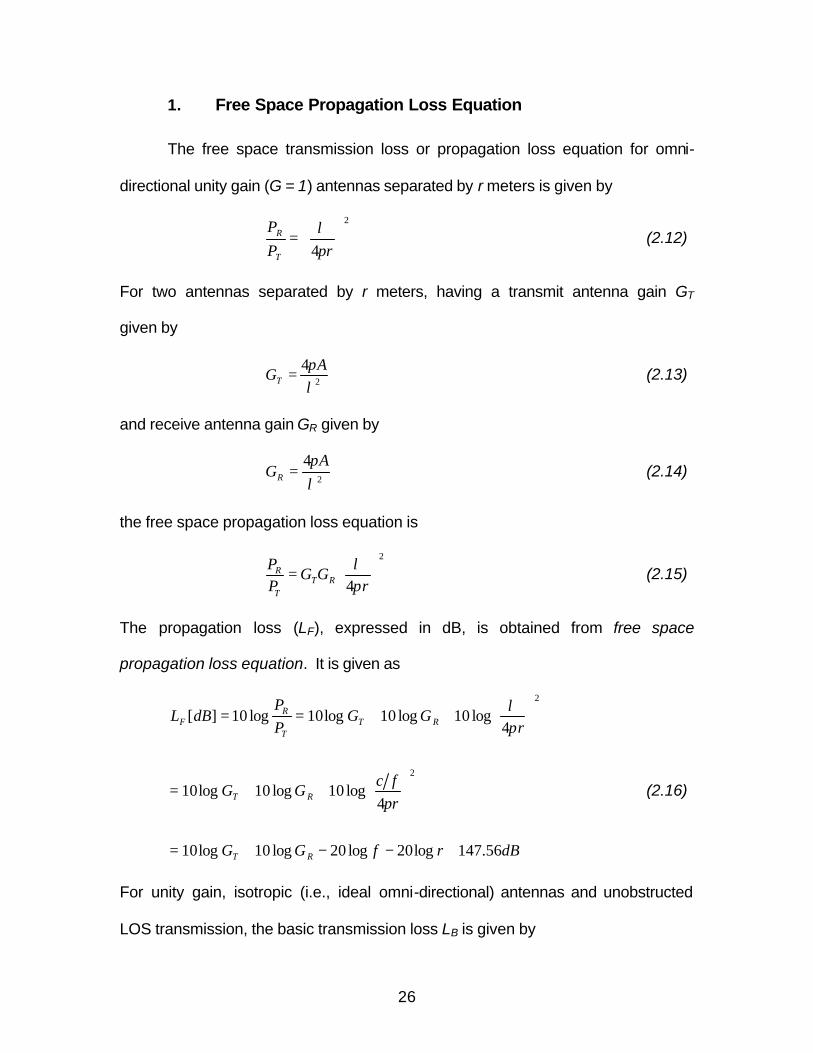
1. Free Space Propagation Loss Equation
The free space transmission loss or propagation loss equation for omni-
directional unity gain (G = 1) antennas separated by r meters is given by
2
4
=
rPP
T
R
πλ
(2.12)
For two antennas separated by r meters, having a transmit antenna gain GT
given by
2
4λπA
GT = (2.13)
and receive antenna gain GR given by
2
4λπA
GR = (2.14)
the free space propagation loss equation is
2
4
=
rGG
PP
RTT
R
πλ
(2.15)
The propagation loss (LF), expressed in dB, is obtained from free space
propagation loss equation. It is given as
dBrfGG
rfc
GG
rGG
PP
dBL
RT
RT
RTT
RF
56.147log20log20log10log10
4log10log10log10
4log10log10log10log10][
2
2
+−−+=
++=
++==
π
πλ
(2.16)
For unity gain, isotropic (i.e., ideal omni-directional) antennas and unobstructed
LOS transmission, the basic transmission loss LB is given by
27
][log20][log2056.27][ mrMHzfdBLB +−+= (2.17)
or
][log20][log2044.32][ kmrMHzfdBLB +−−= (2.18)
From this basic LOS transmission loss equation, we can see that the received
power (relative to transmitted power) decreases by 6 dB for every doubling of
distance and for every doubling of the radio frequency.
2. Path Loss of NLOS and LOS
The majority of land-mobile cellular systems operate in a NLOS
environment, such as those illustrated in Fig. II-3. From equation 2.18, it is noted
that for LOS operation the received power decreases by 1/rn as the distance r
between antennas increases. In summary, mean path loss increases
exponentially with distance. The exponent n for an unobstructed LOS system is
n = 2.
Based on empirical data a general model has been developed for NLOS
propagation and is used by most engineers. The model is given by
n
oB d
dLdL
−
∝)( (2.19)
and indicates that the mean path loss L increases exponentially with distance d,
where
n = path loss exponent; typical range of n is 3.5 ≤ n ≤ 5.
d = distance (separation) between transmit and receive antennas.
do = reference distance or free space propagation corner distance.
28
LB = propagation loss of the LOS path for do [m], - equation 2.17 and 2.18.
L = loss (propagation loss) of the combined NLOS and LOS signal path.
The path loss exponent n indicates how fast path loss increases with
distances. The reference distance, do assumes that there is free space
propagation (unobstructed) between the antenna and do. Practical values for
indoor free space propagation corner distance, do , typically range between 1 and
3 m (or about 3 to 10 feet).
Absolute mean path loss in dB is defined as the path loss in dB from the
transmitter to the reference distance, L(do), plus the additional path loss
described by equation 2.19. Thus the absolute mean path loss L(do) [dB] is
given by
)(log10)(])[( 10 oo ddndLdBdL −= (2.20)
Experimental results indicate that typical NLOS outdoor cellular mobile systems
have a path loss range of 3.5 ≤ n ≤ 5. Indoor channels have a path loss of 2 ≤ n
≤ 4, [8]. Additional experimental results on propagation attenuation
measurements at 900 MHz in mobile PCS environment can be found in [9].
F. DIGITAL MODULATION AND DEMODULATIONS
Simultaneous study and joint optimization of digital modulation techniques
and of microwave components, lead to spectrally efficient, fast transmission
wireless systems. The choice of particular modulation and demodulation
techniques has a major impact on the overall microwave system design,
29
transceiver architecture and intermediate frequency (IF) choice as well as radio
frequency (RF) component specifications. Palm’s Palm VII uses the GMSK
(Gaussian filtered Minimum Shift Keying) digital modulation technique, one of the
most frequently used techniques in wireless communications. This powerful and
spectrally efficient modulation meets the demand for the exploring capacity
requirements by ever increasing numbers of users. A simple overview of the
principles of operation is illustrated here.
Frequency Modulation (FM) is among the most frequently used analog
modulations techniques. For data transmission, a digital FM technique known as
Frequency Shift Keying (FSK) was developed [10]. Logic state 1 corresponds to
transmit frequency 2f , logic state 0 (-1 V data level) to 1f . The deviation for the
coherent FSK is
bpp T
ffff2
12 12 =−=∆=∆ (2.21)
where bT is the unit bit duration of the input data stream. The modulation index
is defined by
bppTfm ∆= (2.22)
The modulation index of FSK systems can be preset to have a narrowband or
wideband digital FSK spectrum. The FSK signal can be represented by
)2sin()2sin()2cos()2cos(
])(2cos[)(
tfftAtfftA
tffAtS
cc
cFSK
∆∆±−∆±=
∆±=
ππππ
π (2.23)
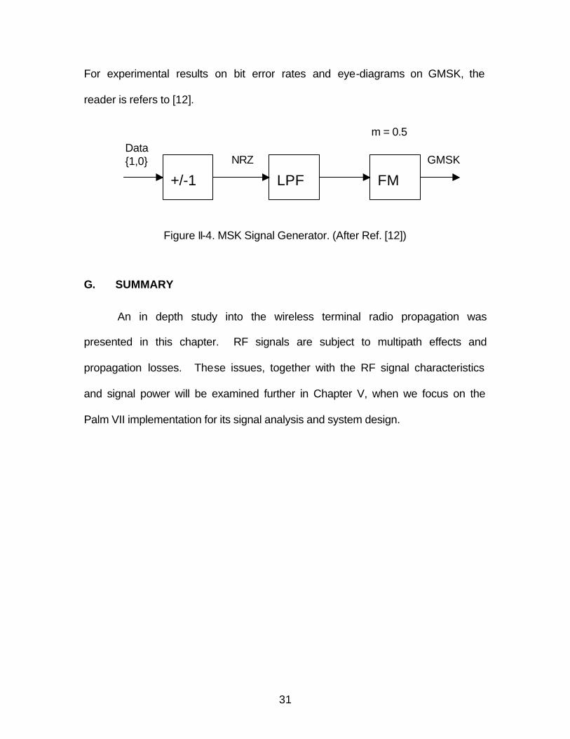
Minimum Shift Keying (MSK) modulation is a special class of FSK with the
modulation index, m, equal to 0.5. It can be generated as shown in Fig. II-4. In
30
1981, Murota and Hirade proposed the use of a pre-modulation Gaussian low-
pass filter to shape the spectrum of MSK [11]. This filter removes the sudden
transitions in the frequency modulation pulses of an MSK signal. The resulting
Gaussian minimum shift keying (GMSK) modulation thus achieves a narrower
spectrum with much attenuated side lobes. Furthermore, GMSK has the
appealing feature that a pre-modulation Gaussian low-pass filter can easily
adjust its spectral shape. GMSK modulation is adopted in many wireless
communication standards, such as the global system for mobile (GSM), and the
second generation cordless telephones. Inserting a Gaussian low-pass filter as a
pre-modulation filter to MSK modulation performs GMSK modulation. Changing
the bandwidth of the Gaussian filter can control the GMSK spectrum. A GMSK
system can be seen as a partial-response digital FM system in which the degree
of inter-symbol interference changes continuously with the Gaussian filter
bandwidth bB . The ability of GMSK to continuously control the band-limitation of
the pre-modulation signal is an advantage over other partial response FM
systems. Palm’s Palm VII has a value of 3.0=TBb . Modulation index of 0.5
corresponds to frequency deviation bTf 41=∆ ; thus, the MSK signal )(tSMSK is
)2sin()2sin()2cos()2cos()( tfTtAtfTtAtS cbcbMSK ππππ ±−±= (2.24)
Equation (2.24) is an MSK quadrature modulation representation of FSK. MSK
modulation has the following fundamental properties:
§ constant envelope suitable for nonlinear power efficient
amplification
§ coherent and noncoherent detection capability
31
For experimental results on bit error rates and eye-diagrams on GMSK, the
reader is refers to [12].
Figure II-4. MSK Signal Generator. (After Ref. [12])
G. SUMMARY
An in depth study into the wireless terminal radio propagation was
presented in this chapter. RF signals are subject to multipath effects and
propagation losses. These issues, together with the RF signal characteristics
and signal power will be examined further in Chapter V, when we focus on the
Palm VII implementation for its signal analysis and system design.
+/-1
FM
LPF
Data {1,0} NRZ
m = 0.5
GMSK

32
THIS PAGE INTENTIONALLY LEFT BLANK
33
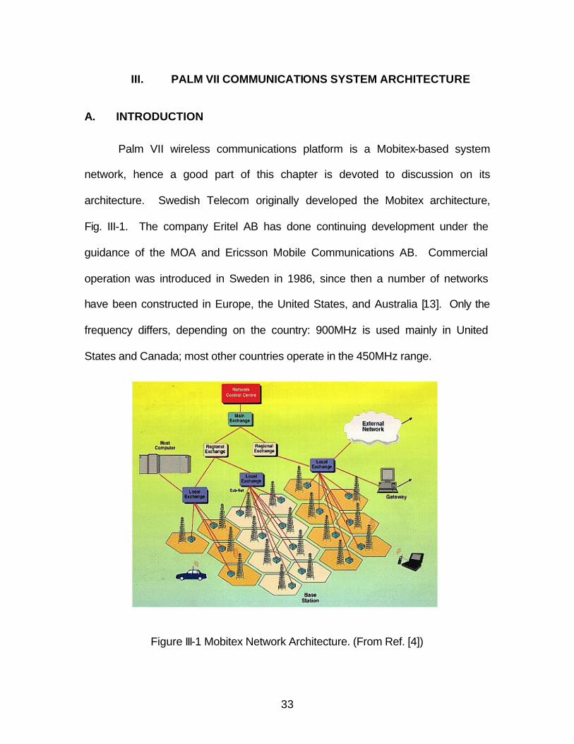
III. PALM VII COMMUNICATIONS SYSTEM ARCHITECTURE
A. INTRODUCTION
Palm VII wireless communications platform is a Mobitex-based system
network, hence a good part of this chapter is devoted to discussion on its
architecture. Swedish Telecom originally developed the Mobitex architecture,
Fig. III-1. The company Eritel AB has done continuing development under the
guidance of the MOA and Ericsson Mobile Communications AB. Commercial
operation was introduced in Sweden in 1986, since then a number of networks
have been constructed in Europe, the United States, and Australia [13]. Only the
frequency differs, depending on the country: 900MHz is used mainly in United
States and Canada; most other countries operate in the 450MHz range.
Figure III-1 Mobitex Network Architecture. (From Ref. [4])
34
The Mobitex system employs a cellular layout in order to provide wireless
communication services to a specific geographical area. It utilizes a hierarchical
structure that may contain up to six levels of network nodes depending on the
size and the area of coverage.
The infrastructure is comprised of three types of nodes: base station, local
switches, and regional switches. The cells served by the same local switch form
a service area or subnets. In each service area, 10 to 30 frequency pairs (called
channels) are allocated to radio service. Each base station usually utilizes from
one to four channels, depending on the anticipated cell loading. All these
channels have 12.5 kHz bandwidth and support a data rate of 8 kbs. The
allocated RF spectrum in the United States is 935 to 940 MHz for the downlink
(base to mobile) and 896 to 901 MHz for the uplink (mobile to base). The base
stations are connected to local switches via local telephone facilities using either
X.25 or a high-level data link control (HDLC) serial link. Similarly, the local
switches are connected to higher-level nodes (regional nodes) via long distance
facilities and usually employ the same data link protocols. At the head of the
hierarchy lies the main exchange, which interconnects with other networks.
Finally, another network element, the network control center (NCC), supports
network-wide management and supervision functions [14].
A key feature of the network is that message switching occurs at the
lowest possible level (not the case for other networks, e.g., CDPD), ensuring
quick response times and reduced backbone traffic. In other words,
communication between two mobile users inside the same cell involves only the
35
cell’s base station. If the mobile users roam in different cells belonging to the
same service area, message turnaround occurs at the same service area’s local
switch. Only mobility, authentication, and other signalling messages need to
travel upwards in order to maintain proper operation. Furthermore, if the link
between a base station and its superior switch is lost, the base station may still
operate in autonomous mode, where it handles only intra-cell communications.
This feature is supported by Ericsson’s BRS2 base station [15].
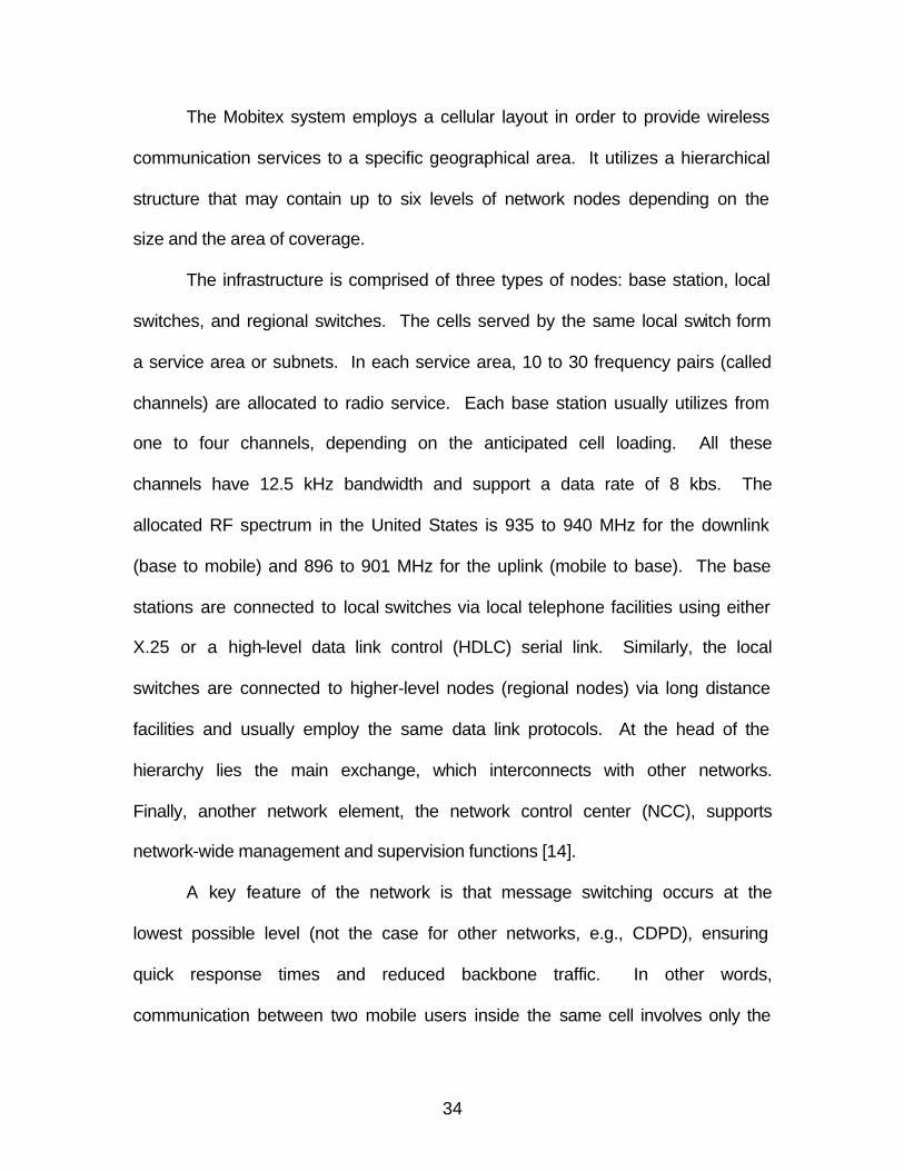
Another key feature of Mobitex is the store-and-forward capabilities, as
shown in Fig. III-2. Each mobile subscription is provided with a mailbox. An
application can specify if a packet should be stored in a mailbox if the user is
unavailable to receive the packet. When the user becomes available, Mobitex
automatically forwards the message to the user. Up to ten messages per
subscription may be stored, and when the subscriber re-establishes contact with
the network, the messages will be forwarded. Messages can be stored for up to
72 hours. The store and forward feature is especially useful when a user's
terminal device is turned off or the user is temporarily out of touch with the
network. In this situation, the store and forward feature enables applications to
hold messages or information for later delivery. Stored messages are then
automatically forwarded when network contact is re-established.
36
Figure III-2. Mobitex Store-and-Forward Capabilities.
B. SUBSCRIPTIONS
Like all cellular phone users, Palm VII users are required to subscribe to
the palm.net services before one can use its wireless connections. The rates
differ accordingly to the type of service plans one subscribes. Network
subscribers can access the network services through a physical network access
point, that is, either a fixed host terminal (connected to a local switch) or a radio
terminal which complies with Mobitex air interface specifications [16]. Standard
connection interfaces are specified for both types of access terminals in order to
establish a standardized access platform. Generally, every fixed host needs a
host terminal subscription; similarly, every radio terminal is associated with a
mobile terminal subscription. Whenever a radio terminal is switched on, it uses
its own subscription profile to register with the nearest base station (range about
37
20 to 30 km or about 12 to 18 miles) and log into the Mobitex system. During this
phase, the radio terminal transmits its Electronic Serial Number (ESN), which is
hard-coded into each radio modem, and the network verifies that the transmitted
ESN matches the ESN stored in its subscription profile. Any mismatch triggers
an alert to the NCC, and a command is sent to the radio terminal, rendering it
inactive.
Furthermore, every individual who needs access to the Mobitex must have
a personal subscription. Every personal subscription is associated with a PMAN
(Personal Mobitex Access Number) and a password, which protects from
unauthorized use, and help with correct billing. In order to access the network a
person must use the nearest access terminal (radio or host terminal) to request
login using his own PMAN and password. The access terminal transmits the
login request to the network side for authentication. In this way, the network
finds out the physical access point (i.e., the address of the employed radio or
host terminal) of every logged in personal subscription, and thus can
subsequently route the subscription’s incoming traffic appropriately. Up to eight
personal subscriptions may be active on a radio terminal at a time. It is to be
noted here that the utilization of both mobile terminal and personal subscriptions
effectively offer personal mobility (a significant concept in personal
communications), because a person may select and use a preferred (and maybe
different) terminal to gain access to the network. Additionally, there are group
subscriptions that comprise a number of mobile and host terminal subscriptions,
and are used for receiving group messages (e.g., from all the field workers of a
38
company). This service minimizes the work of dispatch personnel by
broadcasting identical messages to numerous subscriptions. A group broadcast
message is sent to terminals in a controlled geographical area selected by the
customer. There is no definite acknowledgement from each recipient of a group
broadcast message. However, the network will broadcast a group message
several times. Lastly, there are host group subscriptions that enable a mobile
user to access a group of host computers as if they were a single host, or allow a
single host to have multiple network appearances.
The addresses used to identify subscriptions, group and external networks
are called Mobitex access numbers (MANs).
C. CHANNEL ACCESS
The multiple access protocol in the Mobitex is a variation of the well
known slotted ALOHA [17]. A mobile terminal (MOB) that has traffic to send is
allowed to transmit only during specific free cycles2. These cycles (repeated time
periods) are initiated by the base station in every cell, by transmitting a FREE
frame on the downlink. The free cycles are divided into slots of equal length.
After a FREE frame reception, a ready MOB (one with waiting traffic) randomly
chooses a slot and starts transmission at the beginning of that slot. If a MOB
becomes ready during a free cycle, it transmits at the next available slot. Of
course, due to random access, collisions may occur when two or more MOBs
choose the same slot to transmit.
2 Others, such as CDPD allow terminals to transmit at any time.
39
The slot length (SLOT_LENGTH) as well as the total number of slots
(FREE_SLOTS) in the free cycles is explicitly stated in the FREE frame that
initiated the cycle. Both these variables can change depending on the amount
and length of downlink traffic. The SLOT_LENGTH parameter in the FREE frame
actually specifies the maximum length of a data frame that can be sent without a
preceding access request. To explain this further, consider a MOB that has a
data frame to send. If the total length of the frame is greater than the
SLOT_LENGTH parameter specified in the previous FREE frame, it must send an
access request instead of the data frame itself. At the end of the free cycle the
BASE will grant access permission to every mobile that has successfully sent an
access request. Thus one after the other, the mobiles will eventually transmit
their data frames (though outside of a free cycle) before the next free cycle.
In the Fig. III-3 (a), 5 slots are illustrated with a length of 70 ms each. In
this example, MOB 1 generated the random number “2” and sent a status
message in the second slot, while MOB 2 generated the random number “4” and
sent an access request (ABD). At the end of the free cycle the BASE
acknowledges the status message of MOB 1 and grants access permission to
MOB 2 by transmitting a (properly addressed) access grant frame (ATD).
In the Fig. III-3 (b), another channel activity example is shown. Because
the base station operates in full duplex it can simultaneously receive and transmit
messages. The base station attempts to make the most efficient use of airtime
by arranging messages by size and coordinating with the inbound traffic from the
mobiles. Considering Fig. III-3 (b), after the first FREE frame, the base station
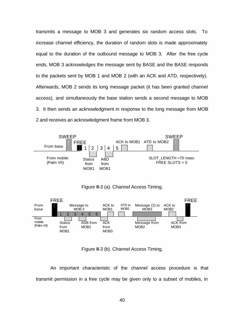
40
transmits a message to MOB 3 and generates six random access slots. To
increase channel efficiency, the duration of random slots is made approximately
equal to the duration of the outbound message to MOB 3. After the free cycle
ends, MOB 3 acknowledges the message sent by BASE and the BASE responds
to the packets sent by MOB 1 and MOB 2 (with an ACK and ATD, respectively).
Afterwards, MOB 2 sends its long message packet (it has been granted channel
access), and simultaneously the base station sends a second message to MOB
3. It then sends an acknowledgment in response to the long message from MOB
2 and receives an acknowledgment frame from MOB 3.
SWEEP SWEEP
From mobile (Palm VII)
Status from
MOB1
ABD from
MOB1
SLOT_LENGTH =70 msec FREE SLOTS = 5
Figure III-3 (a). Channel Access Timing.
FREE FREE
Message to MOB 3
ACK to MOB1
ATD to MOB2
Message (2) to MOB3
ACK to MOB2
From base
1 2 3 4 5 6
From
mobile (Palm VII) Status
from MOB1
ADB from MOB2
ACK from MOB3
Message from MOB2
ACK from MOB3
Figure III-3 (b). Channel Access Timing.
An important characteristic of the channel access procedure is that
transmit permission in a free cycle may be given only to a subset of mobiles, in
FREE ACK to MOB1 ATD to MOB2 From base
1 2 3 4 5
41
order to reduce the number of access attempts. This is accomplished by either
addressing the FREE frame to a number of mobiles (using a specific address
mask field), specifying a priority level (above which transmit permission is
granted), or specifying a particular traffic type (alert, data, etc.) that is acceptable
in the free cycle.
Every data frame (or access request) transmitted by a MOB during a free
cycle must be acknowledged by the BASE before the next FREE frame (i.e.,
before the start of the next free cycle). Frames that have not been
acknowledged (maybe because they have collided) are retransmitted using a
repetition policy managed by the network operator. Generally, a MOB has to
wait for k free cycles before re-transmitting. The specified default value for k is
zero (i.e., retransmission may occur at every free cycle); however, k may become
progressively larger as the repetition number increases. Finally, if too many
repetitions have been tried, the data frame is returned to the network layer and a
recovery mechanism is triggered (usually a roaming procedure) in order to re-
establish a reliable data link contact.
D. ROAMING
The portion of the data link management entity that is responsible for
finding the best network access point (i.e., base station) and retaining the best
radio link quality possible is called the roaming entity. Usually, the roaming entity
deploys the primitives provisioned by the first two or three layers of the OSI
network reference model.
42
The main roaming procedure is somewhat similar in every cellular network
with roaming capabilities. That is, a mobile station monitors the quality of the
currently selected radio channel as well as the quality of other system channels,
which are highly likely to provide an acceptable radio communication. The main
differences that exist in various approaches include the way “quality” is
translated, the means for quality measurement [18], and the frequency of these
measurements.
Mobitex roaming procedures generally conform to the above principle.
Every MOB, in addition to monitoring the signal quality of the currently registered
base station (the CURRENT_BASE), is periodically scanning other system
channels and evaluates the average value of the received signal strength in
these channels. This average value is often referred to as the roaming value of
the channel.
Inside every cell, many variables related to the scanning and channel
measurement processes are broadcast by means of special signalling frames.
The most important frame belonging to this category is the SWEEP frame, which
contains many parameters needed for the operator-assisted roaming. A MOB
that receives a valid SWEEP frame from BASE will update some internally
maintained parameters and will mark the start of a new sweep cycle. Fig. III-4
illustrates the format of a (type 1) SWEEP frame.
43
Figure III-4. Type 1 SWEEP Frame Format.
The primary block is always present in a SWEEP frame, but the following
blocks may or may not exist. Whenever they exist, these blocks identify a list of
neighbor system channels that should be monitored by the MOBs in a specific
cell. Thus, every MOB may use these blocks to maintain in memory a neighbor
(or current channel) list for roaming purposes. It is the job of the network
operation center to properly configure every BASE relative to how often this
channel list will be broadcast and which channels will be included in the list.
The ordinary roaming procedure implemented by every MOB is as follows:
After the reception of a SWEEP frame some internal parameters including the
current channel list are updated. In addition, an internal timer, Ts, is started as
an indication of a new sweep cycle beginning. The concept of sweep cycle is
important in the Mobitex system; it specifies a time period in which a roaming
procedure takes place. At the end of the sweep cycle, all the neighbor channels
MOB (24 bits) 0 0 0 0 1 1 1 1 PRIO(3) MASK(5) BLOCK(8)
TYPE(8)=1 Tx POWER(8) RSSI PROC(8) RSSI PERIOD(8)
TIME_TO_NEXT(8) MAX_REP(8) BASE_STATUS(8) SCAN_TIME(8)
BAD_BASE(8) GOOD_BASE(8) BETTER_BASE(8) 0 0 0 0 0 0 0 0
CRC(16 bits)
Primary block
Number_of_Channels(8) 0 0 0 0 0 0 0 0 Channel 1 – UPFREQ(8) Channel 1 – UPFREQ(8) Channel 2 – UPFREQ(8) Channel 2 – UPFREQ(8) Channel 3 – UPFREQ(8) Channel 3 – UPFREQ(8) Channel 4 – UPFREQ(8) Channel 4 – UPFREQ(8)
CRC(16 bits)
Block #1
44
are evaluated and the best BASE station is chosen. A typical sweep cycle
duration is 10s.
Timer Ts will time out after a period t which depends on the terminal’s own
subscription number3 (MAN) according to the following relations:
t = TIME_TO_NEXT – 10 ms – SCAN_TIME,
if MAN is even, or
t = TIME_TO_NEXT – 10 ms – 2 * SCAN_TIME,
if MAN is odd
where SCAN_TIME is the overall length of the neighbor-channel scanning period
(including channel switching) and TIME_TO_NEXT is the interval before the next
SWEEP frame. All these parameters are defined in the primary block of a
SWEEP frame (Fig. III-4).
System channels specified in SWEEP frames are scanned by the MOB in
a round robin fashion, and a roaming value is evaluated for each one. As
indicated in the following Fig. III-5:
3 Partitioning the mobile terminals in this way ensures that data traffic can be forwarded to terminals with even (odd) MANs while terminals with odd (even) MANs are in the midst of normal channel monitoring.
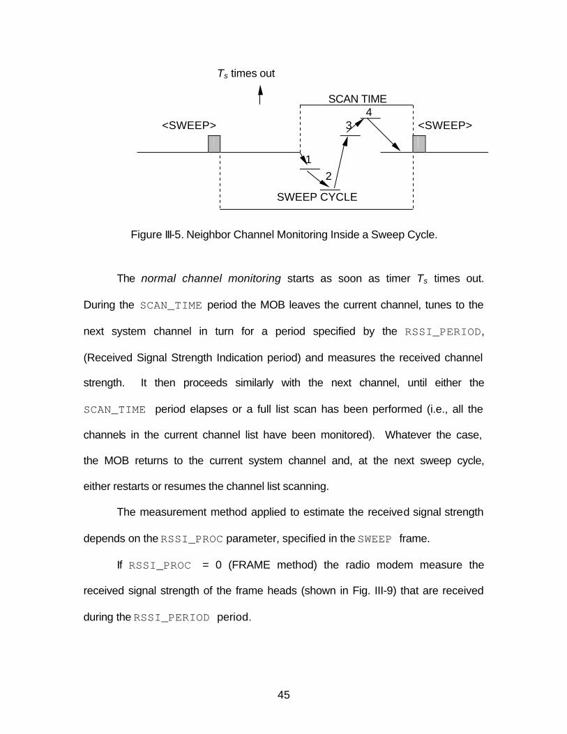
45
Ts times out
SCAN TIME 4
<SWEEP> 3 <SWEEP>
1 2
SWEEP CYCLE
Figure III-5. Neighbor Channel Monitoring Inside a Sweep Cycle.
The normal channel monitoring starts as soon as timer Ts times out.
During the SCAN_TIME period the MOB leaves the current channel, tunes to the
next system channel in turn for a period specified by the RSSI_PERIOD,
(Received Signal Strength Indication period) and measures the received channel
strength. It then proceeds similarly with the next channel, until either the
SCAN_TIME period elapses or a full list scan has been performed (i.e., all the
channels in the current channel list have been monitored). Whatever the case,
the MOB returns to the current system channel and, at the next sweep cycle,
either restarts or resumes the channel list scanning.
The measurement method applied to estimate the received signal strength
depends on the RSSI_PROC parameter, specified in the SWEEP frame.
If RSSI_PROC = 0 (FRAME method) the radio modem measure the
received signal strength of the frame heads (shown in Fig. III-9) that are received
during the RSSI_PERIOD period.
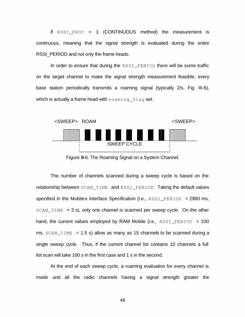
46
If RSSI_PROC = 1 (CONTINUOUS method) the measurement is
continuous, meaning that the signal strength is evaluated during the entire
RSSI_PERIOD and not only the frame heads.
In order to ensure that during the RSSI_PERIOD there will be some traffic
on the target channel to make the signal strength measurement feasible, every
base station periodically transmits a roaming signal (typically 2/s, Fig. III-6),
which is actually a frame head with roaming_flag set.
<SWEEP> ROAM <SWEEP>
SWEEP CYCLE
Figure III-6. The Roaming Signal on a System Channel.
The number of channels scanned during a sweep cycle is based on the
relationship between SCAN_TIME and RSSI_PERIOD. Taking the default values
specified in the Mobitex Interface Specification (i.e., RSSI_PERIOD = 2960 ms,
SCAN_TIME = 3 s), only one channel is scanned per sweep cycle. On the other
hand, the current values employed by RAM Mobile (i.e., RSSI_PERIOD = 100
ms, SCAN_TIME = 1.5 s) allow as many as 15 channels to be scanned during a
single sweep cycle. Thus, if the current channel list contains 10 channels a full
list scan will take 100 s in the first case and 1 s in the second.
At the end of each sweep cycle, a roaming evaluation for every channel is
made and all the radio channels having a signal strength greater the
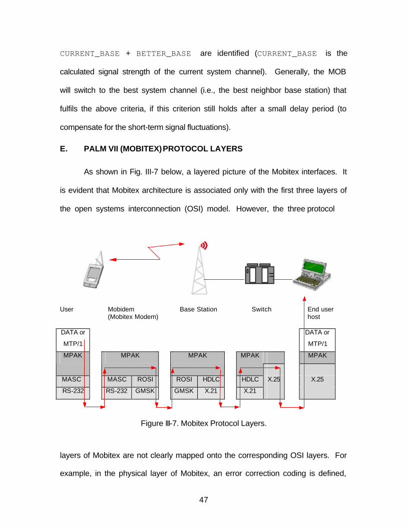
47
CURRENT_BASE + BETTER_BASE are identified (CURRENT_BASE is the
calculated signal strength of the current system channel). Generally, the MOB
will switch to the best system channel (i.e., the best neighbor base station) that
fulfils the above criteria, if this criterion still holds after a small delay period (to
compensate for the short-term signal fluctuations).
E. PALM VII (MOBITEX) PROTOCOL LAYERS
As shown in Fig. III-7 below, a layered picture of the Mobitex interfaces. It
is evident that Mobitex architecture is associated only with the first three layers of
the open systems interconnection (OSI) model. However, the three protocol
User Mobidem Base Station Switch End user
(Mobitex Modem) host DATA or
MTP/1
DATA or
MTP/1
MPAK MPAK MPAK MPAK MPAK
MASC MASC ROSI ROSI HDLC HDLC X.25 X.25
RS-232 RS-232 GMSK GMSK X.21 X.21
Figure III-7. Mobitex Protocol Layers.
layers of Mobitex are not clearly mapped onto the corresponding OSI layers. For
example, in the physical layer of Mobitex, an error correction coding is defined,
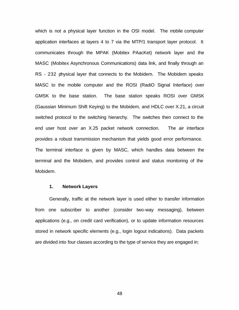
48
which is not a physical layer function in the OSI model. The mobile computer
application interfaces at layers 4 to 7 via the MTP/1 transport layer protocol. It
communicates through the MPAK (Mobitex PAacKet) network layer and the
MASC (Mobitex Asynchronous Communications) data link, and finally through an
RS - 232 physical layer that connects to the Mobidem. The Mobidem speaks
MASC to the mobile computer and the ROSI (RadiO Signal Interface) over
GMSK to the base station. The base station speaks ROSI over GMSK
(Gaussian Minimum Shift Keying) to the Mobidem, and HDLC over X.21, a circuit
switched protocol to the switching hierarchy. The switches then connect to the
end user host over an X.25 packet network connection. The air interface
provides a robust transmission mechanism that yields good error performance.
The terminal interface is given by MASC, which handles data between the
terminal and the Mobidem, and provides control and status monitoring of the
Mobidem.
1. Network Layers
Generally, traffic at the network layer is used either to transfer information
from one subscriber to another (consider two-way messaging), between
applications (e.g., on credit card verification), or to update information resources
stored in network specific elements (e.g., login logout indications). Data packets
are divided into four classes according to the type of service they are engaged in:
49
a. PSUBCOM-Class Packets
PSUBCOM-class packets transfer information from one subscriber
(or application) to another, such as text messages, data messages, status
messages, and higher protocol data messages. The message type is encoded in
the type field of a packet, so the network element and application can treat the
various types accordingly.
b. PSOSCOM-Class Packets
PSOSCOM-class packets are used to transfer alert messages (i.e.,
high-priority data traffic)
c. CSUBCOM-Class Packets
CSUBCOM-class packets are used to set-up and control circuit-
switched connections (to support real time connections). These kinds of packets
are not used in data communication, so we do not pay any further attention to
this class.
d. DTESERV-Class Packets
DTESERV-class packets are basically network-layer signalling
packets used to update status information. For example, they are used to
change the status of personal and group subscriptions (e.g., login logout
requests), to change a terminal’s status (e.g., active-inactive messages), and to
transfer terminal specific information (e.g., terminal information
request/response) to the network.
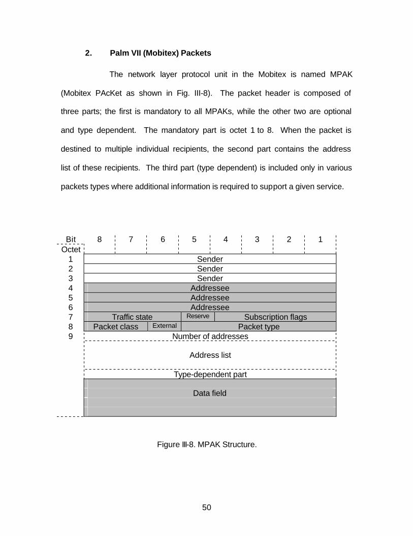
50
2. Palm VII (Mobitex) Packets
The network layer protocol unit in the Mobitex is named MPAK
(Mobitex PAcKet as shown in Fig. III-8). The packet header is composed of
three parts; the first is mandatory to all MPAKs, while the other two are optional
and type dependent. The mandatory part is octet 1 to 8. When the packet is
destined to multiple individual recipients, the second part contains the address
list of these recipients. The third part (type dependent) is included only in various
packets types where additional information is required to support a given service.
Figure III-8. MPAK Structure.
Bit Octet
8 7 6 5 4 3 2 1
1 Sender 2 Sender 3 Sender 4 Addressee 5 Addressee 6 Addressee 7 Traffic state Reserve Subscription flags 8 Packet class External Packet type 9 Number of addresses Address list Type-dependent part Data field
51
a. Sender and Addressee Field
The fields sender and addressee inside an MPAK contain
subscription numbers (MANs) of the originator and recipient of the packet. The
sender MAN can be a terminal subscription, personal subscription, or network
MAN, while the addressee MAN may be all these plus a group MAN.
b. Traffic State Flags
Traffic state flags represent the transfer status of a message and
are checked during an MPAK reception. They encode various error conditions in
cases where a packet is undeliverable (e.g. congestion, bad format, network
busy). If traffic state flags indicate no error (traffic state = 0), the received MPAK
is forwarded to the ultimate destination: the upper layer or the network-layer
management entity. Furthermore, if a message comes from the user mailbox
(placed earlier, when the user was not available), the traffic state flags will
indicate this. Also, if we are attempting to transmit a packet to a recipient who is
currently unavailable, the packet will be placed in a recipient mailbox for future
delivery, and will return with a traffic state flag indicating so.
c. Subscription Flags
Subscription flags are set by the packet originator to define whether
the packet may or may not be stored in the recipient’s mailbox, if a positive
acknowledgment for this packet is needed (packets are by default not
acknowledged at the network layer), if the packet contains an address list inside,
and so on.
52
d. Packet Class and Packet Type
Finally, the packet class associates the packet with one of the four
classes of services: PSUBCOM, PSOSCOM, DTESESRV, and CSUBCOM, and
the packet type specifies an individual type within the designated class. For
example, a text message will have PSUBCOM class and type = 1, while a data
message will have the same class but type = 2. Similarly, if we try to log in, the
login request message will have DTESERV class and type = 1.
A unique feature of Mobitex is the possibility to forward one packet to a
number of recipients. In order to efficiently utilize radio resources, the originator
does not transmit multiple copies of the same packet, but only one packet, which
include the desired recipients list in the header. The direct addressee for this
packet is the Mobitex network (this is a special address). The first network node
that receives the packet (i.e., the selected BASE station) will split the packet into
a number of individual packets, each addressed to a recipients included in the
original address list. Afterwards, each packet is separately switched through the
wireline or wireless facilities.
3. Data Link Layer
The data link layer specifies the functions used to provide efficient, error-
free transmission over the wireless medium. It mainly provides the functionality
of the data link layer as defined in the OSI model. It implements functions for
error detection and correction through a block-selective ARQ scheme, channel
multi-access algorithms, priority facilities and roaming procedures. Generally,
the data link layer ensures proper communication with the Mobitex infrastructure
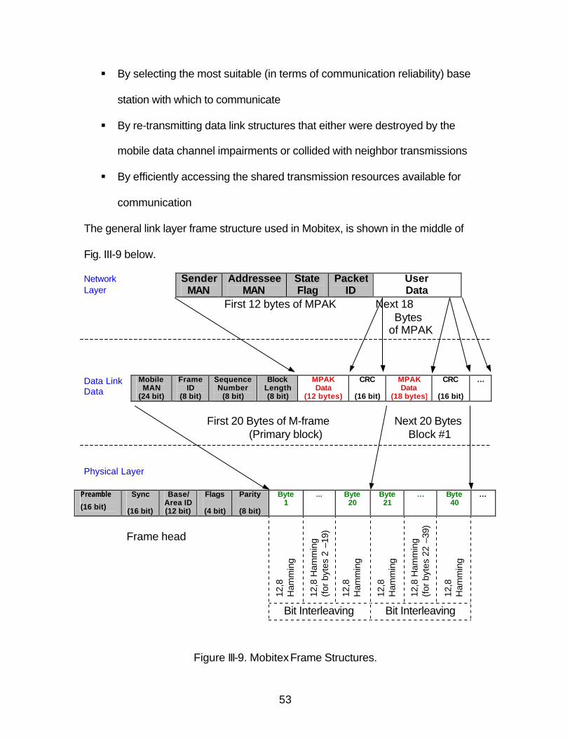
53
§ By selecting the most suitable (in terms of communication reliability) base
station with which to communicate
§ By re-transmitting data link structures that either were destroyed by the
mobile data channel impairments or collided with neighbor transmissions
§ By efficiently accessing the shared transmission resources available for
communication
The general link layer frame structure used in Mobitex, is shown in the middle of
Fig. III-9 below.
Network Layer
Sender MAN
Addressee MAN
State Flag
Packet ID
User Data
First 12 bytes of MPAK Next 18 Bytes
of MPAK Data Link Data
Mobile MAN
(24 bit)
Frame ID
(8 bit)
Sequence Number
(8 bit)
Block Length (8 bit)
MPAK Data
(12 bytes)
CRC
(16 bit)
MPAK Data
(18 bytes)
CRC
(16 bit)
…
First 20 Bytes of M-frame Next 20 Bytes (Primary block) Block #1 Physical Layer
Preamble
(16 bit)
Sync
(16 bit)
Base/ Area ID (12 bit)
Flags
(4 bit)
Parity
(8 bit)
Byte 1
… Byte 20
Byte 21
… Byte 40
…
Frame head
12,8
H
amm
ing
12,8
Ham
min
g
(for
byt
es 2
–19
)
12,8
H
amm
ing
12,8
H
amm
ing
12,8
Ham
min
g
(for
byt
es 2
2 –3
9)
12,8
H
amm
ing
Bit Interleaving Bit Interleaving
Figure III-9. Mobitex Frame Structures.
54
It consists of a series of blocks, each one with a constant size of 20 bytes
and each with a 16-bit CRC (Cyclic Redundancy Check) appended at the end for
error protection.
The first block is the primary block and contains mandatory link control
information. The link address (MOB MAN) at the beginning specifies the address
of a mobile terminal, which either has generated the frame, or is the immediate
destination of the frame. Additionally, the primary block specifies the type of the
frame, the numbers of blocks in the frame, the sequence number of the frame,
and the number of valid bytes in the block. The following blocks, MPAK Data,
CRC etc. may or may not exist depending on the frame type.
The data link layer employs a block selective repeat automatic repeat
request (ARQ) scheme [19] to efficiently recover from transmission errors. That
is, after a frame transmission (say from mobile to base) the addressee checks
the received blocks for errors. If all the blocks are correct, it replies with an ACK
frame (positive acknowledgement); otherwise, it replies with a repetition request
REB frame that explicitly indicates which blocks have to be re-transmitted. There
may be cases, for example, when the primary block is corrupted or a frame is
addressed to a group, where a recipient should not transmit an
acknowledgement. Actually, there is a single flag in the link header that indicates
if an acknowledgement is needed for a particular frame. It should be noted that a
frame is transmitted only after the previous one has been acknowledged, i.e., a
stop-and-wait ARQ scheme is employed at the frame level.
55
The data link protocol of Mobitex is quite different and simpler than the
data link protocol of CDPD. The latter is HDLC-based and establishes data link
connections between the mobile terminals and the network, whereas, the former
is a custom connectionless protocol. Omnisky’s service for Palm V, Handspring
and HP Jornada is one example of a CDPD service. Similar wireless
applications can be accessed, however a comparison and contrast of the merits
of the two technologies is beyond the scope of the thesis.
4. Physical Layer
The physical layer protocol describes the way in which the mobile terminal
handles the radio channel. Various functions implemented in the physical layer
include frame and bit synchronization, slot synchronization (during the free
cycle), system channel identification, base station and area identification,
received signal strength measurement, transmission power level setting, and
error correction coding. As already mentioned, the error correction coding is not
a physical layer function in the OSI reference model.
a. Physical Layer Frame Structure
In order to achieve high transmission reliability the link layer frames
are divided into blocks, and each block is separately coded. The physical layer
frame structure is depicted in lower part of Fig. III-9. It starts with a frame head
that is used to establish synchronization and to uniquely a base radio station.
The preamble field includes a synchronization pattern that enables all the
prospective receivers to acquire bit synchronization and to correctly decode the
56
rest of the frame. It contains eight pairs of alternating 1s and 0s. If the frame is
transmitted from a base station the patterns starts with a couple of 1’s (i.e.,
1100110011001100), whereas when a mobile station transmits it, the patterns
starts with a couple of 0’s (i.e., 0011001100110011). In other words, the physical
layer can identify if the frame comes from a base station or from another mobile
station (whereupon it will probably be discarded).
The SYNC code word that follows is used to establish frame
synchronization. It is important to note that every Mobitex network maintains its
own, unique SYNC code word; thus, SYNC is used as network identification
number at the physical layer. The Mobitex specification defines that in order to
roam into base stations in other networks, it should be possible to manually
change the frame synchronization word from the application layer. However, it is
clear that if a mobile receives frames from a network, which uses a different
SYNC (from that currently selected), it will be discarded at the physical layer.
The BASE_ID and AREA_ID field uniquely identified the base radio station
in a Mobitex network. Frames originated from a BASE will carry its own base
and area IDs, while frames originated from radio terminals will carry the base and
area IDs of the destination base. Obviously, (from Fig. III-9.) there may be up to
64 (26) areas in every network and each area and may contain up to 64 (26) base
stations. These IDs fields make it feasible for a radio channel to accept physical
layers frames from only one base station (the one selected by the roaming
entity). If, maybe due to favorable propagation conditions, a mobile station
receives a frame from a distance base station, these frames will be discarded.
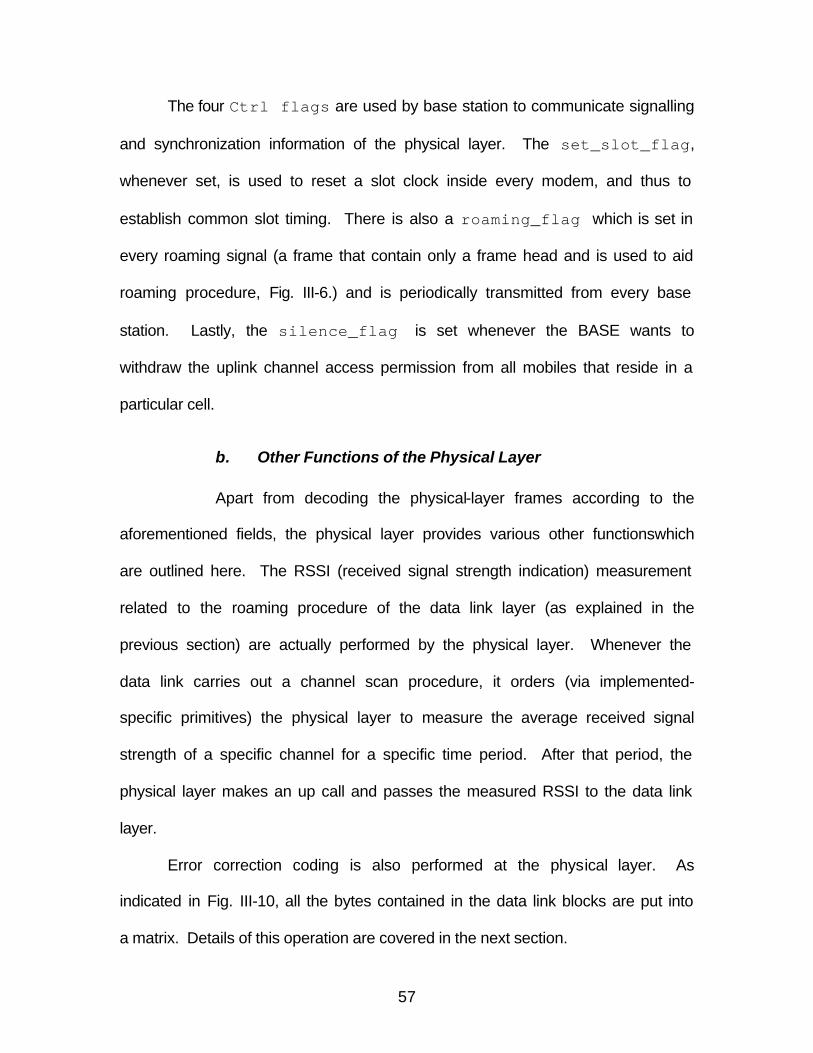
57
The four Ctrl flags are used by base station to communicate signalling
and synchronization information of the physical layer. The set_slot_flag,
whenever set, is used to reset a slot clock inside every modem, and thus to
establish common slot timing. There is also a roaming_flag which is set in
every roaming signal (a frame that contain only a frame head and is used to aid
roaming procedure, Fig. III-6.) and is periodically transmitted from every base
station. Lastly, the silence_flag is set whenever the BASE wants to
withdraw the uplink channel access permission from all mobiles that reside in a
particular cell.
b. Other Functions of the Physical Layer
Apart from decoding the physical-layer frames according to the
aforementioned fields, the physical layer provides various other functionswhich
are outlined here. The RSSI (received signal strength indication) measurement
related to the roaming procedure of the data link layer (as explained in the
previous section) are actually performed by the physical layer. Whenever the
data link carries out a channel scan procedure, it orders (via implemented-
specific primitives) the physical layer to measure the average received signal
strength of a specific channel for a specific time period. After that period, the
physical layer makes an up call and passes the measured RSSI to the data link
layer.
Error correction coding is also performed at the physical layer. As
indicated in Fig. III-10, all the bytes contained in the data link blocks are put into
a matrix. Details of this operation are covered in the next section.
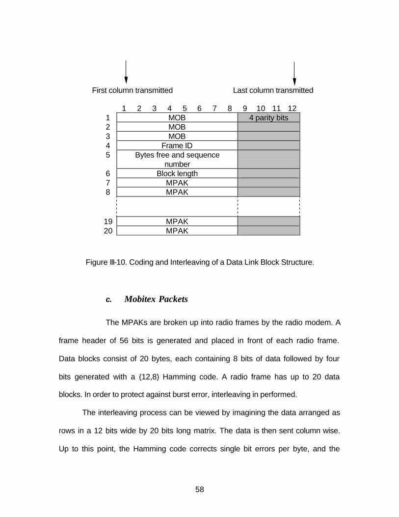
58
First column transmitted Last column transmitted
1 2 3 4 5 6 7 8 9 10 11 12 1 MOB 4 parity bits 2 MOB 3 MOB 4 Frame ID 5 Bytes free and sequence
number
6 Block length 7 MPAK 8 MPAK
19 MPAK 20 MPAK
Figure III-10. Coding and Interleaving of a Data Link Block Structure.
c. Mobitex Packets
The MPAKs are broken up into radio frames by the radio modem. A
frame header of 56 bits is generated and placed in front of each radio frame.
Data blocks consist of 20 bytes, each containing 8 bits of data followed by four
bits generated with a (12,8) Hamming code. A radio frame has up to 20 data
blocks. In order to protect against burst error, interleaving in performed.
The interleaving process can be viewed by imagining the data arranged as
rows in a 12 bits wide by 20 bits long matrix. The data is then sent column wise.
Up to this point, the Hamming code corrects single bit errors per byte, and the
59
interleaved code allows a burst of 20 errors to be corrected. The data following
the frame head is then scrambled through a nine-stage scrambler, which
generates a sequence identical to the recommended test sequence described in
ITU-T Recommendation V.52. Scrambling provides a mechanism to achieve DC
voltage balance by eliminating long sequences of ones and zeros in the data
stream.
After the above processing stages, the logic sequence for transmission is
converted into a binary non-return to zero (NRZ) waveform with an 8 kb/s rate.
This digital waveform is filtered by a lowpass filter with a linear phase
characteristic (usually a Gaussian filter is used [20]) and passed directly to the
FM (frequency modulation) modulator input. The frequency deviation is set to
yield a transmitted frequency 2 kHz higher (when the logic 1 is sent) or 2 kHz
lower (when a logic 0 is sent) than the channel frequency; that is, the modulation
index is 0.5. With these setting the RF channel bandwidth is restricted to 12.5
kHz.
Mobitex radio modems are also capable of dynamic power control. This
capability provides increased capacity in high-density service areas. Reducing
the base stations’ coverage pattern and adding more base stations can increase
the number of cells in a service area.
Finally, as has already implied, the transmission mode is full duplex for the
base stations and two-frequency simplex for the radio terminals. The Mobitex
specification indicates that the receive/transmit switching times of a radio modem
should be kept less than 20 ms in order to maintain high system efficiency.
60
F. SUMMARY
In this chapter, we learned about subscriptions, roaming, and channel
access of Palm VII wireless hand-helds. Detailed discussions of the different
protocol layers are presented. This knowledge helps develop the framework for
collection of these RF signals, which will be discussed in the next chapter.
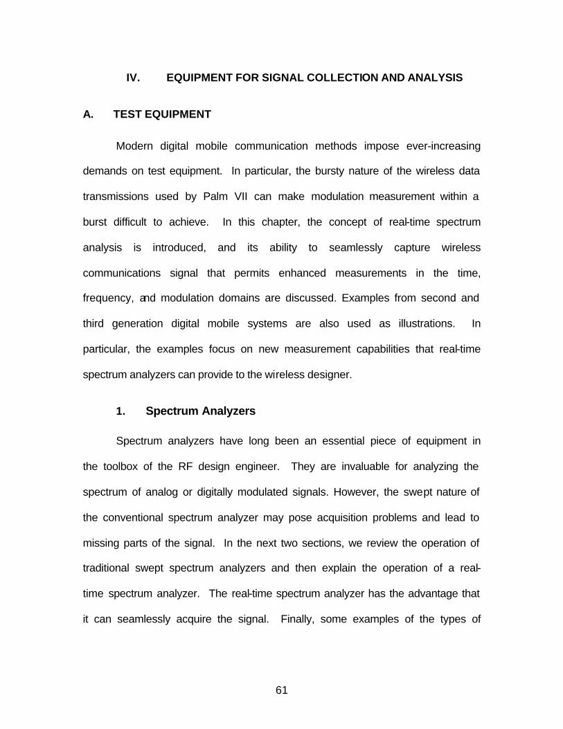
61
IV. EQUIPMENT FOR SIGNAL COLLECTION AND ANALYSIS
A. TEST EQUIPMENT
Modern digital mobile communication methods impose ever-increasing
demands on test equipment. In particular, the bursty nature of the wireless data
transmissions used by Palm VII can make modulation measurement within a
burst difficult to achieve. In this chapter, the concept of real-time spectrum
analysis is introduced, and its ability to seamlessly capture wireless
communications signal that permits enhanced measurements in the time,
frequency, and modulation domains are discussed. Examples from second and
third generation digital mobile systems are also used as illustrations. In
particular, the examples focus on new measurement capabilities that real-time
spectrum analyzers can provide to the wireless designer.
1. Spectrum Analyzers
Spectrum analyzers have long been an essential piece of equipment in
the toolbox of the RF design engineer. They are invaluable for analyzing the
spectrum of analog or digitally modulated signals. However, the swept nature of
the conventional spectrum analyzer may pose acquisition problems and lead to
missing parts of the signal. In the next two sections, we review the operation of
traditional swept spectrum analyzers and then explain the operation of a real-
time spectrum analyzer. The real-time spectrum analyzer has the advantage that
it can seamlessly acquire the signal. Finally, some examples of the types of
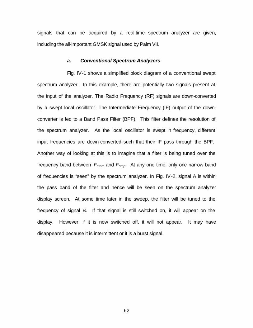
62
signals that can be acquired by a real-time spectrum analyzer are given,
including the all-important GMSK signal used by Palm VII.
a. Conventional Spectrum Analyzers
Fig. IV-1 shows a simplified block diagram of a conventional swept
spectrum analyzer. In this example, there are potentially two signals present at
the input of the analyzer. The Radio Frequency (RF) signals are down-converted
by a swept local oscillator. The Intermediate Frequency (IF) output of the down-
converter is fed to a Band Pass Filter (BPF). This filter defines the resolution of
the spectrum analyzer. As the local oscillator is swept in frequency, different
input frequencies are down-converted such that their IF pass through the BPF.
Another way of looking at this is to imagine that a filter is being tuned over the
frequency band between Fstart and Fstop. At any one time, only one narrow band
of frequencies is “seen” by the spectrum analyzer. In Fig. IV-2, signal A is within
the pass band of the filter and hence will be seen on the spectrum analyzer
display screen. At some time later in the sweep, the filter will be tuned to the
frequency of signal B. If that signal is still switched on, it will appear on the
display. However, if it is now switched off, it will not appear. It may have
disappeared because it is intermittent or it is a burst signal.
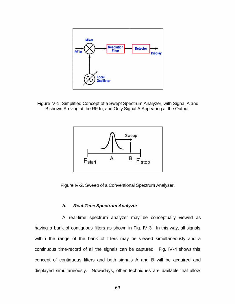
63
Figure IV-1. Simplified Concept of a Swept Spectrum Analyzer, with Signal A and B shown Arriving at the RF In, and Only Signal A Appearing at the Output.
Figure IV-2. Sweep of a Conventional Spectrum Analyzer.
b. Real-Time Spectrum Analyzer
A real-time spectrum analyzer may be conceptually viewed as
having a bank of contiguous filters as shown in Fig. IV-3. In this way, all signals
within the range of the bank of filters may be viewed simultaneously and a
continuous time-record of all the signals can be captured. Fig. IV-4 shows this
concept of contiguous filters and both signals A and B will be acquired and
displayed simultaneously. Nowadays, other techniques are available that allow
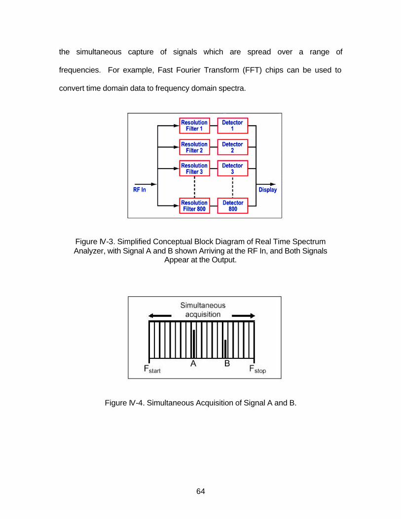
64
the simultaneous capture of signals which are spread over a range of
frequencies. For example, Fast Fourier Transform (FFT) chips can be used to
convert time domain data to frequency domain spectra.
Figure IV-3. Simplified Conceptual Block Diagram of Real Time Spectrum Analyzer, with Signal A and B shown Arriving at the RF In, and Both Signals
Appear at the Output.
Figure IV-4. Simultaneous Acquisition of Signal A and B.
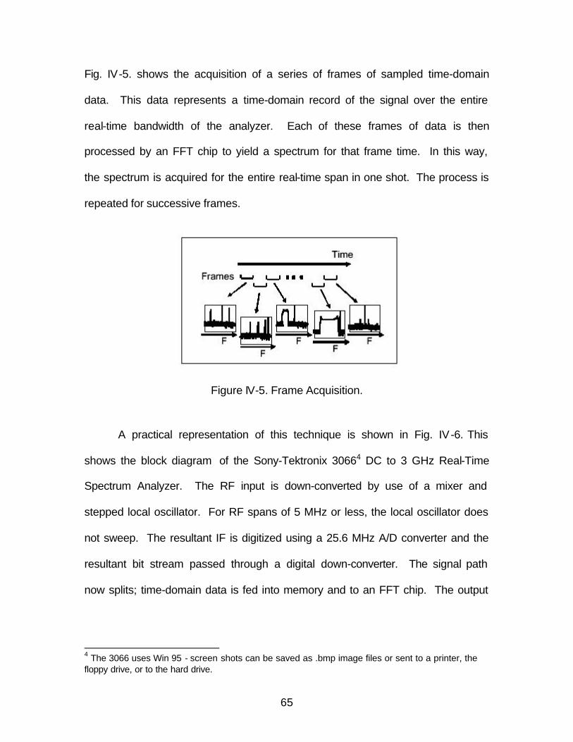
65
Fig. IV-5. shows the acquisition of a series of frames of sampled time-domain
data. This data represents a time-domain record of the signal over the entire
real-time bandwidth of the analyzer. Each of these frames of data is then
processed by an FFT chip to yield a spectrum for that frame time. In this way,
the spectrum is acquired for the entire real-time span in one shot. The process is
repeated for successive frames.
Figure IV-5. Frame Acquisition.
A practical representation of this technique is shown in Fig. IV-6. This
shows the block diagram of the Sony-Tektronix 30664 DC to 3 GHz Real-Time
Spectrum Analyzer. The RF input is down-converted by use of a mixer and
stepped local oscillator. For RF spans of 5 MHz or less, the local oscillator does
not sweep. The resultant IF is digitized using a 25.6 MHz A/D converter and the
resultant bit stream passed through a digital down-converter. The signal path
now splits; time-domain data is fed into memory and to an FFT chip. The output
4 The 3066 uses Win 95 - screen shots can be saved as .bmp image files or sent to a printer, the floppy drive, or to the hard drive.
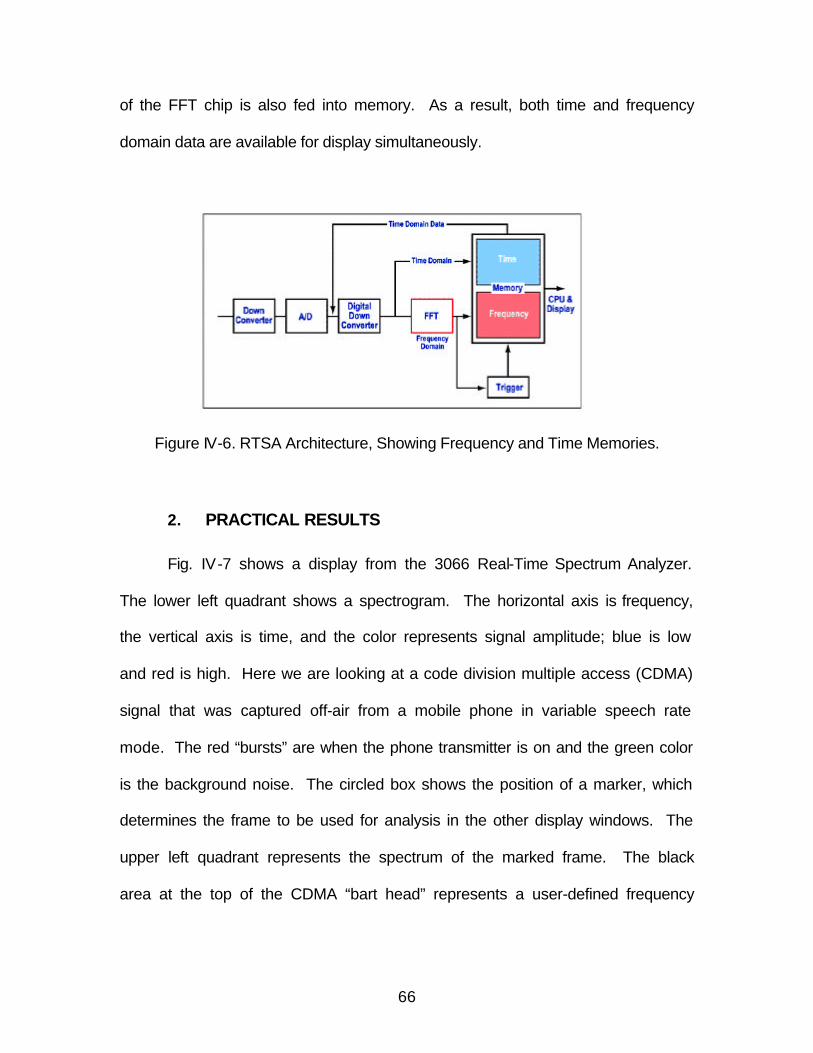
66
of the FFT chip is also fed into memory. As a result, both time and frequency
domain data are available for display simultaneously.
Figure IV-6. RTSA Architecture, Showing Frequency and Time Memories.
2. PRACTICAL RESULTS
Fig. IV-7 shows a display from the 3066 Real-Time Spectrum Analyzer.
The lower left quadrant shows a spectrogram. The horizontal axis is frequency,
the vertical axis is time, and the color represents signal amplitude; blue is low
and red is high. Here we are looking at a code division multiple access (CDMA)
signal that was captured off-air from a mobile phone in variable speech rate
mode. The red “bursts” are when the phone transmitter is on and the green color
is the background noise. The circled box shows the position of a marker, which
determines the frame to be used for analysis in the other display windows. The
upper left quadrant represents the spectrum of the marked frame. The black
area at the top of the CDMA “bart head” represents a user-defined frequency
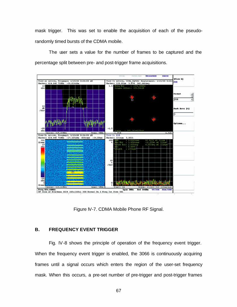
67
mask trigger. This was set to enable the acquisition of each of the pseudo-
randomly timed bursts of the CDMA mobile.
The user sets a value for the number of frames to be captured and the
percentage split between pre- and post-trigger frame acquisitions.
Figure IV-7. CDMA Mobile Phone RF Signal.
B. FREQUENCY EVENT TRIGGER
Fig. IV-8 shows the principle of operation of the frequency event trigger.
When the frequency event trigger is enabled, the 3066 is continuously acquiring
frames until a signal occurs which enters the region of the user-set frequency
mask. When this occurs, a pre-set number of pre-trigger and post-trigger frames
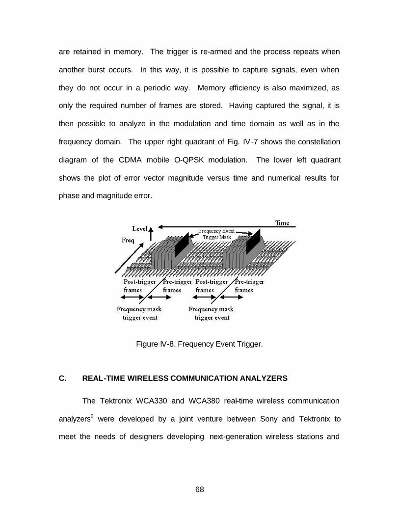
68
are retained in memory. The trigger is re-armed and the process repeats when
another burst occurs. In this way, it is possible to capture signals, even when
they do not occur in a periodic way. Memory efficiency is also maximized, as
only the required number of frames are stored. Having captured the signal, it is
then possible to analyze in the modulation and time domain as well as in the
frequency domain. The upper right quadrant of Fig. IV-7 shows the constellation
diagram of the CDMA mobile O-QPSK modulation. The lower left quadrant
shows the plot of error vector magnitude versus time and numerical results for
phase and magnitude error.
Figure IV-8. Frequency Event Trigger.
C. REAL-TIME WIRELESS COMMUNICATION ANALYZERS
The Tektronix WCA330 and WCA380 real-time wireless communication
analyzers5 were developed by a joint venture between Sony and Tektronix to
meet the needs of designers developing next-generation wireless stations and
69
emerging protocol products challenged by compliance with an increasing number
of telecommunications standards. The WCA330 and WCA380 wireless
communication analyzers rely on Tektronix’s proven real-time spectrum analysis
technology to acquire a wide swath of information (in frequency terms, a 30 MHz
bandwidth) from a modulated digital wireless signal. This large volume of
information-derived from just one fast acquisition-becomes the raw material for
thorough analysis of wireless signal parameters such as Code Domain Power,
Adjacent Channel Power, and much more. These measurements apply both to
present-day standards and to emerging 3GPP (Third Generation Partnership
Project) -compliant technologies. As real-time instruments, the WCA330 and
WCA380 can capture transient events that conventional spectrum analyzers
simply cannot. As discussed in the earlier Section IV-A-1-a, conventional
spectrum analyzers sweep the spectrum over time taking a section or slice rather
than taking an entire block of data as a real-time instrument does. This is
contrasted in Section IV-A-1-b, where real-time acquisition reveals trends
accumulated over many acquisitions.
The WCA380 model has DC-to-8 GHz bandwidth, ample for 3GPP needs,
including spurious harmonics and downlink signals. The WCA330 has DC-to-3
GHz bandwidth, which meets the needs of today's prevailing standards. Both
models offer demodulation capability for standards ranging from GMSK to the
latest 3GPP and Bluetooth.
5 The WCA will have Win 98. Options available similar to footnote 3, with the improved newer version of window using Win 98.
70
D. ACCESSORIES
The other apparati needed to set-up for the intercept and collection of this
RF signal are discussed in this section. There are the antenna for the RF signal
reception, the adjustable tripod for the support of the antenna and the low loss
coaxial cable for connecting the antenna to the RTSA.
1. Antenna
To receive the RF signals from Palm VII and the base station, the
integrated antenna that comes with every Palm VII is a natural choice for this
application. This antenna is detachable from Palm VII. The antenna is shown in
Fig. IV-9.
2. Adjustable Tripod6
The adjustable tripod comes with a variety of clamping devices, for various
antenna-tripod combinations. As the name suggest, the tripod allows height
adjustment of the antenna position setup convenience. The stand is specially
designed with wooden frame to reduce field disturbance and allow clean
collection of the signal from free space. This tripod would be ideal in the
experiment for the collection of the RF signal in the thesis.
3. Low loss Coaxial Cable7
Coaxial cable is an important element as far as RF loss concerned. By
using a low loss, short length cable, it will be helpful in the collection of the RF
6 Tektronix order number: 016-1102-00 7 Tektronix order number: 012-1291-00
71
signal from free space. The cable couples directly from the antenna to the
spectrum analyzer (male fittings).
Figure IV-9. Palm VII’s Antenna.
E. EQUIPMENT SET-UP
For the installation of the real time spectrum analyzer, the author
proposed one rack for mounting. A full set-up for this RF signals collection would
be similar to the diagram shown in Fig. IV-10. Recall, the considerations for this
set-up are:
• The bursty nature of the wireless data transmissions used by Palm VII
can make modulation measurement within a burst difficult to achieve.
Antenna
72
The swept nature of the conventional spectrum analyzer may pose
acquisition problems and lead to missing parts of the signal. Thus
Real-Time spectrum analyzer is recommended for capturing the signal.
• The reception power is strong at NPS, up to 90% signal strength is
achievable in some locations, thus any open area to mount the
receiving Log-Periodic antenna is reasonable. However, the RTSA
must be connected close enough to the antenna to prevent extensive
cable loss.
Figure IV-10. Equipment Setup for the RF Signal Collections.
Base Station
Log-Periodic Antenna
Wireless PDA - Palm VII
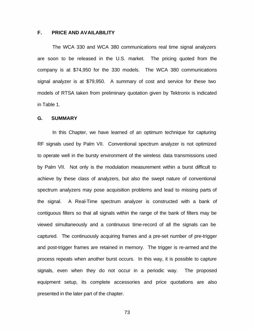
73
F. PRICE AND AVAILABILITY
The WCA 330 and WCA 380 communications real time signal analyzers
are soon to be released in the U.S. market. The pricing quoted from the
company is at $74,950 for the 330 models. The WCA 380 communications
signal analyzer is at $79,950. A summary of cost and service for these two
models of RTSA taken from preliminary quotation given by Tektronix is indicated
in Table 1.
G. SUMMARY
In this Chapter, we have learned of an optimum technique for capturing
RF signals used by Palm VII. Conventional spectrum analyzer is not optimized
to operate well in the bursty environment of the wireless data transmissions used
by Palm VII. Not only is the modulation measurement within a burst difficult to
achieve by these class of analyzers, but also the swept nature of conventional
spectrum analyzers may pose acquisition problems and lead to missing parts of
the signal. A Real-Time spectrum analyzer is constructed with a bank of
contiguous filters so that all signals within the range of the bank of filters may be
viewed simultaneously and a continuous time-record of all the signals can be
captured. The continuously acquiring frames and a pre-set number of pre-trigger
and post-trigger frames are retained in memory. The trigger is re-armed and the
process repeats when another burst occurs. In this way, it is possible to capture
signals, even when they do not occur in a periodic way. The proposed
equipment setup, its complete accessories and price quotations are also
presented in the later part of the chapter.
74
ITEM WCA 330
(USD)
WCA 380
(USD)
RSTA 74,950.00 79,950.00
Services - 3 Years 2,975.00 3,120.00
Calibration data 425.00 440.00
Service test data 850.00 875.00
Repair - 3 years 2,005.00 2,110.00
Table 1. Setup Quotes for WCA 330/380.
75
V. PALM VII SIGNAL ANALYSIS AND SYSTEM DESIGN
In this Chapter, RF signal power measurements are carried out in field
experiments. Based on Palm VII built-in function, Diagnostic, the reception
quality is captured for both indoors and outdoor environments. The results are
presented and discussed. Further, in the absence of a hardware facility to
conduct the signal analysis at NPS, the author has consulted Tektronix’s
Wireless Communications Laboratory to analyze Palm VII’s RF signal
characteristics. Based on the Palm VII signal descriptions, pseudo-random
signals were generated and intercepted using a Real-Time Spectrum Analyzer
(RTSA). Screen shots from the RTSA display are presented and analyzed.
A. SIGNAL STRENGTH RECEPTION ON PALM VII
Keeping the RF signal propagation characteristics in mind, it is essential to
find out what signal strength performance can be achieved by an actual
commercial wireless communication device, the case in point, Palm VII.
Palm.net provides a built-in function called Diagnostic, which allows users to
monitor the reception quality of the environment he/she is operating in. It uses its
antenna, hence, one must raise the antenna to activate and use this function, to
monitor the RF signal strength of the environment. Palm VII shows two screens
for this function, one in a graphical form of bar chart, which indicates signal
strength in percentage, and the other screen in a tabular detail text, which shows
up readily when the Detail icon is clicked. This table is shown in Table 2. One
can utilized this diagnostic function even if he/she did not subscribe to Palm.net,
or what Palm Inc. refers to as Service Activation.
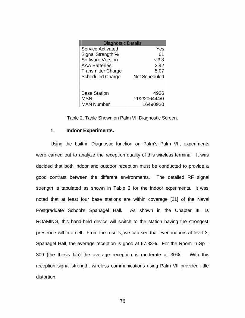
76
Diagnostic Details Service Activated Yes Signal Strength % 61 Software Version v.3.3 AAA Batteries 2.42 Transmitter Charge 5.07 Scheduled Charge Not Scheduled Base Station 4936 MSN 11/2/206444/0 MAN Number 16490920
Table 2. Table Shown on Palm VII Diagnostic Screen.
1. Indoor Experiments.
Using the built-in Diagnostic function on Palm’s Palm VII, experiments
were carried out to analyze the reception quality of this wireless terminal. It was
decided that both indoor and outdoor reception must be conducted to provide a
good contrast between the different environments. The detailed RF signal
strength is tabulated as shown in Table 3 for the indoor experiments. It was
noted that at least four base stations are within coverage [21] of the Naval
Postgraduate School's Spanagel Hall. As shown in the Chapter III, D.
ROAMING, this hand-held device will switch to the station having the strongest
presence within a cell. From the results, we can see that even indoors at level 3,
Spanagel Hall, the average reception is good at 67.33%. For the Room in Sp –
309 (the thesis lab) the average reception is moderate at 30%. With this
reception signal strength, wireless communications using Palm VII provided little
distortion.
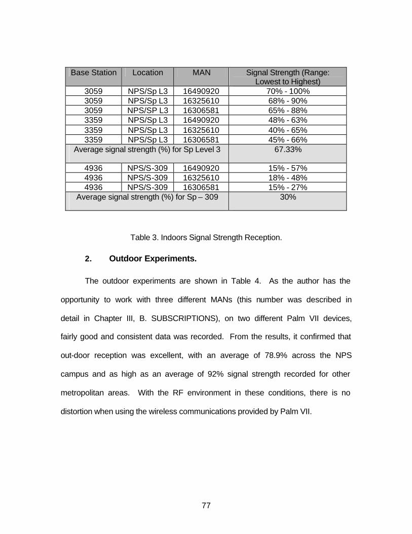
77
Base Station Location MAN Signal Strength (Range: Lowest to Highest)
3059 NPS/Sp L3 16490920 70% - 100% 3059 NPS/Sp L3 16325610 68% - 90% 3059 NPS/SP L3 16306581 65% - 88% 3359 NPS/Sp L3 16490920 48% - 63% 3359 NPS/Sp L3 16325610 40% - 65% 3359 NPS/Sp L3 16306581 45% - 66%
Average signal strength (%) for Sp Level 3 67.33%
4936 NPS/S-309 16490920 15% - 57% 4936 NPS/S-309 16325610 18% - 48% 4936 NPS/S-309 16306581 15% - 27%
Average signal strength (%) for Sp – 309 30%
Table 3. Indoors Signal Strength Reception.
2. Outdoor Experiments.
The outdoor experiments are shown in Table 4. As the author has the
opportunity to work with three different MANs (this number was described in
detail in Chapter III, B. SUBSCRIPTIONS), on two different Palm VII devices,
fairly good and consistent data was recorded. From the results, it confirmed that
out-door reception was excellent, with an average of 78.9% across the NPS
campus and as high as an average of 92% signal strength recorded for other
metropolitan areas. With the RF environment in these conditions, there is no
distortion when using the wireless communications provided by Palm VII.
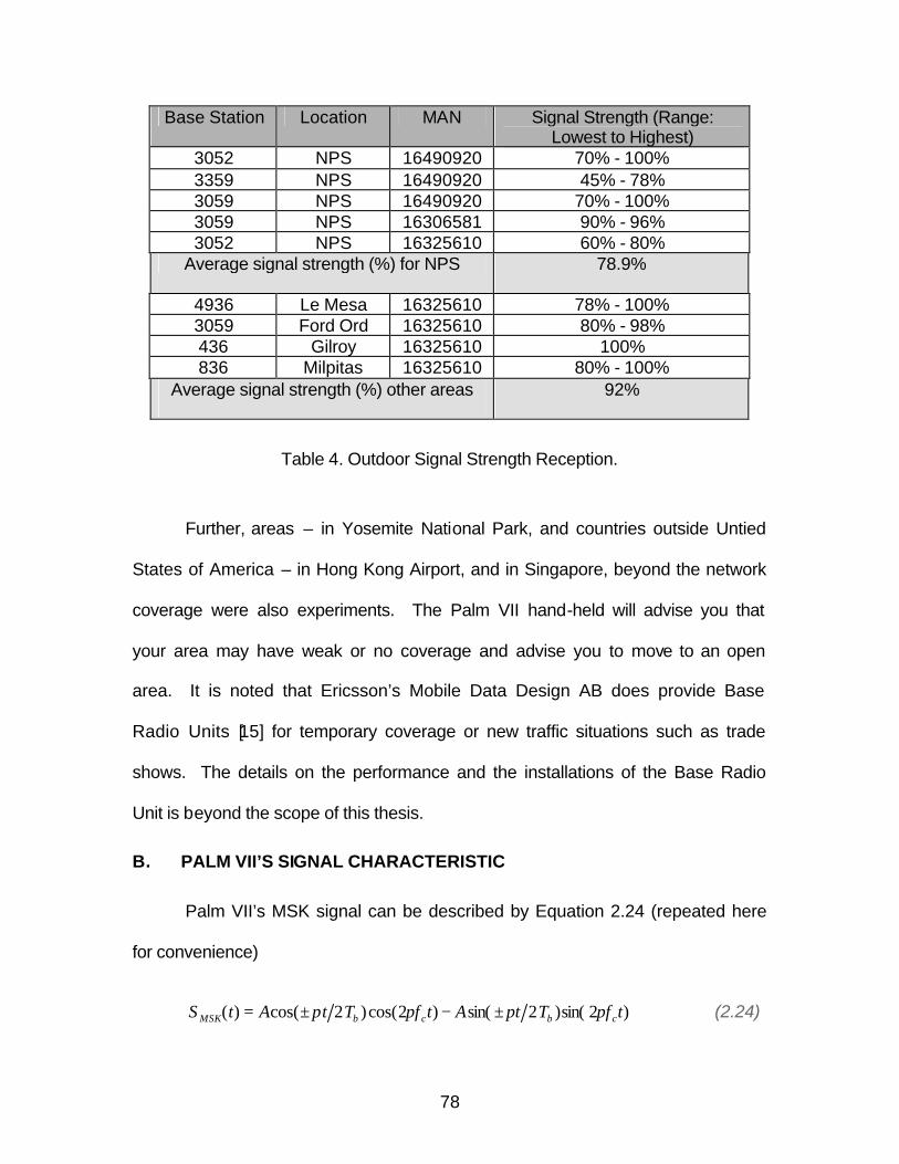
78
Base Station Location MAN Signal Strength (Range: Lowest to Highest)
3052 NPS 16490920 70% - 100% 3359 NPS 16490920 45% - 78% 3059 NPS 16490920 70% - 100% 3059 NPS 16306581 90% - 96% 3052 NPS 16325610 60% - 80%
Average signal strength (%) for NPS 78.9%
4936 Le Mesa 16325610 78% - 100% 3059 Ford Ord 16325610 80% - 98% 436 Gilroy 16325610 100% 836 Milpitas 16325610 80% - 100%
Average signal strength (%) other areas 92%
Table 4. Outdoor Signal Strength Reception.
Further, areas – in Yosemite National Park, and countries outside Untied
States of America – in Hong Kong Airport, and in Singapore, beyond the network
coverage were also experiments. The Palm VII hand-held will advise you that
your area may have weak or no coverage and advise you to move to an open
area. It is noted that Ericsson’s Mobile Data Design AB does provide Base
Radio Units [15] for temporary coverage or new traffic situations such as trade
shows. The details on the performance and the installations of the Base Radio
Unit is beyond the scope of this thesis.
B. PALM VII’S SIGNAL CHARACTERISTIC
Palm VII’s MSK signal can be described by Equation 2.24 (repeated here
for convenience)
)2sin()2sin()2cos()2cos()( tfTtAtfTtAtS cbcbMSK ππππ ±−±= (2.24)
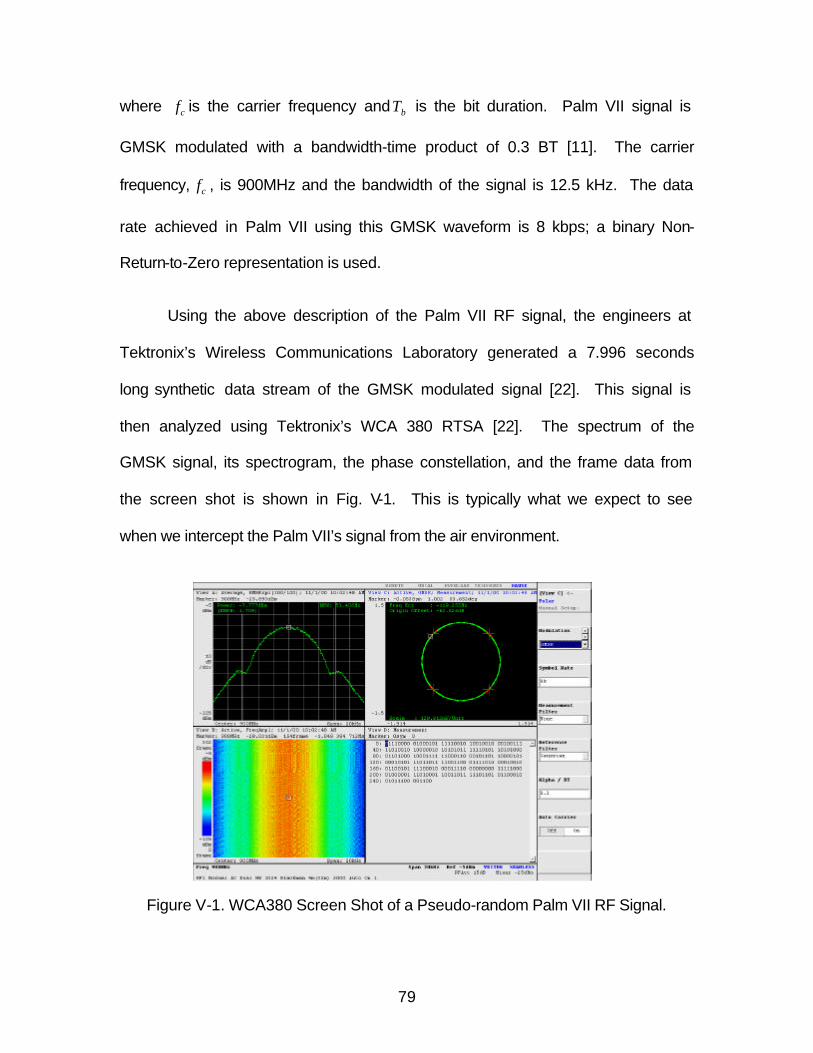
79
where cf is the carrier frequency and bT is the bit duration. Palm VII signal is
GMSK modulated with a bandwidth-time product of 0.3 BT [11]. The carrier
frequency, cf , is 900MHz and the bandwidth of the signal is 12.5 kHz. The data
rate achieved in Palm VII using this GMSK waveform is 8 kbps; a binary Non-
Return-to-Zero representation is used.
Using the above description of the Palm VII RF signal, the engineers at
Tektronix’s Wireless Communications Laboratory generated a 7.996 seconds
long synthetic data stream of the GMSK modulated signal [22]. This signal is
then analyzed using Tektronix’s WCA 380 RTSA [22]. The spectrum of the
GMSK signal, its spectrogram, the phase constellation, and the frame data from
the screen shot is shown in Fig. V-1. This is typically what we expect to see
when we intercept the Palm VII’s signal from the air environment.
Figure V-1. WCA380 Screen Shot of a Pseudo-random Palm VII RF Signal.
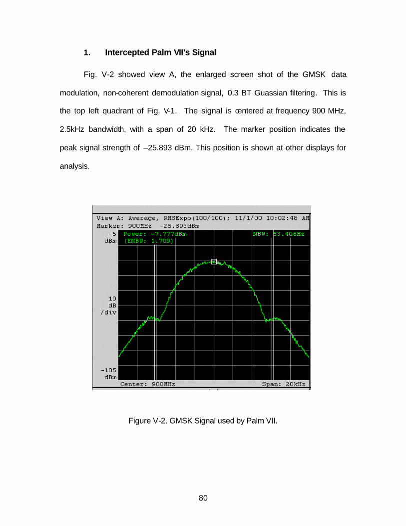
80
1. Intercepted Palm VII’s Signal
Fig. V-2 showed view A, the enlarged screen shot of the GMSK data
modulation, non-coherent demodulation signal, 0.3 BT Guassian filtering. This is
the top left quadrant of Fig. V-1. The signal is centered at frequency 900 MHz,
2.5kHz bandwidth, with a span of 20 kHz. The marker position indicates the
peak signal strength of –25.893 dBm. This position is shown at other displays for
analysis.
Figure V-2. GMSK Signal used by Palm VII.
81
2. Palm VII’s Spectrogram
The Fig. V-3, view B below, shows the enlarged display from the WCA330
Real-Time Spectrum Analyzer. This is the lower left quadrant of Fig. V-1. The
horizontal axis is frequency, the vertical axis is time, and the color represents
signal amplitude, blue color is lowest at –105 dBm, and red color is highest at –5
dBm. From the figure, the marker is positioned on the red signal, which indicates
the specific frame to be used for analysis in the other display windows. This
marker data is indicated at the top of Fig. IV-11, which shows 900MHz, -
23.013dBm, and is the 154th frame. The frame spanned from 0 to 302 frames.
Figure V-3. Palm VII’s Spectrogram
82
3. Phase Constellations of GMSK Signal
Fig. V-4, view C below, shows the enlarged display from WCA 330
analyzer of the GMSK signal space constellations diagram.
Figure V-4. Phase Constellation of GMSK Signal.
83
4. Palm VII’s Frame Analysis
Fig. V-5, view D below shows the enlarged display from WCA 330
analyzer of the Palm VII’s data frame details. Using the knowledge from the
frame characteristic described in Chapter III-E-4, analysis of this frame data will
reveal the content of the signal, taking into consideration the interleaving
procedures involved when sending data from the terminal.
Figure V-5. Palm’s Frame.

84
THIS PAGE INTENTIONALLY LEFT BLANK
85
VI. CONCLUSIONS AND RECOMMENDATIONS
A. CONCLUSIONS
The engineering contributions of this thesis include the analysis of the RF
environment operated by the wireless hand-helds. The RF propagation
properties and its loss characteristics were studied in detail. A detailed review of
an advanced wireless communication protocol stack is presented and its merits
were discussed. Moreover, to analyse the RF characteristerics, state-of-the-art
test equipments were identified. The framework and its system design for the
collection of the RF data were proposed. Finally, field measurements of the
signal strength were conducted, and the expected intercepted RF signals were
presented.
The explosive growth of wireless handheld devices in the last decade and
into the new millennium, and its high penetration rate on customers in a variety of
fields has left no doubt that wireless communications will be the next wave of
data communication exchange. This phenomenon has motivated the author to
research into the devices operating in this media that have taken the world by
storm. The objective of this thesis has been to develop an architecture for
analysis and collection of radio frequency signals used by wireless hand-held
devices in computer communications. Palm’s premium model, Palm VII, is a
state-of-the-art device for digital mobile data communications and one of a few
fully integrated hand-helds that come with a complete transceiver, including
antenna.
86
This thesis project has been an extended learning process about wireless
computer communications – in the different layers of the OSI model, and its
associated technologies. The author has gained a substantial amount of
knowledge and technical know-how from completing this thesis project, including,
and not limited to, the areas of advanced technology mobile communications, its
related RF characteristics, digital mobile communication, its modulation and
demodulation and related of wireless technologies.
The thesis examined the basic features of a mobile terminal and provided
a comprehensive understanding on why convenience in accessing data is the
key and mantras such as “Anywhere, Anytime” have proven their meaning. Next,
the building blocks and the essential technological advance components of the
mobile devices are analyzed. This explains why the hand-held needs to be light
in weight and low in power consumption. With many established and emerging
wireless technologies, it is essential to employ a superior network that has
advantages over other systems. Features, such as open architecture, reliability,
supportability and a wide area of coverage, have an edge over rival systems.
Mobile packet data technology offer by the Mobitex system used by Palm’s Palm
VII PDA meet such criteria.
Modern digital mobile communication methods impose ever-increasing
demands on test equipment. In particular, the burst nature of the wireless data
transmissions used by Palm VII can make modulation measurement within a
burst difficult to achieve. The thesis proposed an optimum way to captured this
digital signal by using the real-time spectrum analysis developed by Tektronix.
87
B. RECOMMENDATIONS
To realize the ultimate goal of capturing the RF signal used by Palm VII, a
real time spectrum analyzer (RTSA) is required. With this tool, along with the
real-time intercepted data, further analysis can be conducted to verify and
examine the actual RF signal used by Palm VII. This will allow a detailed
understanding of Palm VII’s communication network, its architecture and RF
characteristics.
In addition, further investigation of the Mobitex base station needs to be
undertaken. This thesis has examined the wireless terminal using the Mobitex
Network. A study of the base station would augment this work and provide a
foundation for future development. A specific application might consist of setting
up a base station within a DoD’s compound and using hand-helds for efficient
and effective wireless communication among its staff.

88
THIS PAGE INTENTIONALLY LEFT BLANK
89
LIST OF REFERENCES
[1] “Palm VII Handheld Technology,” White paper, http://www.palm.com/europe/prdesk/docs/wireless_tech_wpaper.pdf, Palm Computing Inc. 5400 Bayfront Plaza, Santa Clara, CA 95052. [2] “Palm VII User Manual,” Palm Computing Inc. 5400 Bayfront Plaza, Santa Clara, CA 95052. [3] M. Mobeen Khan, “Wireless data over RAM’s Mobitex network,” SPIE, Vol. 2601, pp 48, June 1995. [4] “Bellsouth Mobile Data,” http://www.data-mobile.com/bmd02010.html, BellSouth Corporation Headquarters, 1155 Peachtree St. NE, Atlanta, GA 30309-3610. [5] Bob Emmerson and David Greetham, Computer Telephony and Wireless Technology: Future Directions in Communications, Computer Technology Research Corp, 1999. [6] John G. Proakis, Digital Communications, McGraw-Hill, New York, 1989. [7] Jakes, William C., Microwave Mobile Communications, Wiley, John & Sons, Incorporated, New York, NY, October 1984. [8] Kamilo Feher, Wireless Digital Communications: Modulation and Spread Spectrum Applications, Prentice Hall, Upper Saddle River, NJ, 1995. [9] “Personal, Indoor and Mobile Radio Communications,” Proceedings of the Third IEEE International Symposium, 1992. [10] R.W. Lucky, J. Salz, and J. Weldon, Principles of Data Communication, McGraw-Hill, New York, 1968. [11] K. Murota and K. Hirade, “GMSK modulations for digital mobile radio telephony,” IEEE Transactional Communications, Vol. COM-29, pp 1044-1050, July 1981. [12] Yoshihiko Akaiwa, Introduction to Digital Mobile Communication, Wiley, John & Sons, Incorporated, New York, NY, October 1997. [13] M. Khan and J. Kilpatrick, “Mobitex and Mobile Data Standards,” IEEE Communications Magazine, Vol. 33, No. 3, pp 96 – 101, March 1995.
90
[14] “Mobile Data Communication – Guide to Mobitex,” Ericsson Mobile Communication AB, Mobile Data Division, ESPIDER-164 80 Stockholm, Sweden, March 1993. [15] “Ericsson Base Radio Unit,” http://www.ericsson.se/wireless/products/mobsys/mobitex/subpages/mprod/mnetcomp/mprodbdet.shtml, Ericsson Inc., 740 East Campbell Road, Richardson, TX 75081. [16] “Mobitex Interface Specification,” RAM Mobile Data, 10 Woodbridge Center Drive, Woodbridge, NJ 07095, 1994. [17] D. Bertsekas and R. Gallager, Data Networks, Englewood Cliffs, NJ, Prentice-Hall, pp 247, 1992. [18] V.O.K. Li and X. Qiu, “Personal Communication Systems (PCS),” IEEE Proceeding, Vol 83, No. 9, pp 1210-43, September 1995. [19] William Stallings, Data & Computer Communications, Sixth Edition, Prentice Hall, November 1999. [20] E.J. Resweber, “ADSP GMSK Modem for Mobitex and other Wireless Infrastructures,” Telecommunications Applications with the TMS3205x DSPs, Application Book, Texas Instruments, 1994. [21] “The Palm.Net™ ZIP Code look-up table,” http://wireless.palm.net/coverage/, Palm Computing Inc. 5400 Bayfront Plaza, Santa Clara, CA 95052. [22] Dave McDonald, [email protected], private communications, Beaverton, OR, Tektronix, Inc. July – September 2000.
91
INITIAL DISTRIBUTION LIST
1. Defense Technical Information Center ……………….………………..…… 2 8725 John H. Kingman Rd., STE 0944 Ft. Belvoir, Virginia 22060-6218
2. Dudley Knox Library ……...…………………………………………………… 2 Naval Postgraduate School 411 Dyer Rd. Monterey, California 93943-5000
3. Chairman, Coded EC ……………………..……………………………………1 Department of Electrical and Computer Engineering Naval Postgraduate School Monterey, California 93943-5121
4. Professor John C. McEachen, Code EC/Mj …...………………………….…1 Department of Electrical and Computer Engineering Naval Postgraduate School Monterey, California 93943-5121
5. Professor Murali Tummala, Code EC/Tu .....….….………………………….1 Department of Electrical and Computer Engineering Naval Postgraduate School Monterey, California 93943-5121
6. Engineering & Technology Curricular Officer ….…………………………….1 Naval Postgraduate School 1 University Circle, Code 34 Monterey, California 93946-5207
7. Mr Teo Hoon Beng ….………………………………………………………….1 HQ RSN, Naval Logistics Department – Weapon Electronics 303 Gombak Drive, Singapore 669645 Republic of Singapore
8. Maj Chua Guan Hwa ...…………………………………………………………2 HQ RSN, Naval Logistics Department – Weapon Electronics 303 Gombak Drive, Singapore 669645 Republic of Singapore
9. Ms Chia Li Li .……………………………………………………………………1 Century Mansions 2M Jalan Remaja, #05-05, Singapore 668671 Republic of Singapore
92
10. Naval Engineering Logistics Office ……………………….…………………1 4555 Overlook Ave. SW Code 5707 Washington DC 20375-5707
11. Department of Defense .………………………………………………………1 9800 Savage Road Ft. Meade MD 20755 ATTN: R531


![RF Generic Signals Application Plug-in Programmer Manual › manual › RF-Generic-Signals-Plug-in-Progr… · RFGSignal:CARRier[n]:DMODulation:APSK Sets or returns the APSK Modulation](https://img.pdfslide.net/doc/110x75/5f1c418e35e4bb2ee83601f3/rf-generic-signals-application-plug-in-programmer-manual-a-manual-a-rf-generic-signals-plug-in-progr.jpg)