Embed Size (px)
Citation preview

Bertaska 1 32nd Annual AIAA/USU
Conference on Small Satellites
SSC18-WKIII-03
An Educational Platform for Small Satellite Development with Proximity Operation
Capabilities
Ivan R. Bertaska and John Rakoczy
NASA Marshall Space Flight Center
Mailstop EV41 Huntsville, AL 35812; (256) 544-6427
ABSTRACT
An alternative to ground testing of small satellites is presented here, where the kinematics of a 3U underactuated
CubeSat operating in 3 degrees-of-freedom (DOF) is reproduced by an omnidirectional wheeled platform, while
satellite dynamics are simulated in real-time. The system is equipped with a relative navigation sensor in the form
factor of a smartphone, the Smartphone Video Guidance Sensor (SVGS), allowing the platform to reproduce proximity
operation maneuvers. The wheeled platform is used as an educational tool for students over a large range of academic
levels, from high school to graduate school. A derivation of the kinematic relationship from satellite dynamics to
rotacaster wheel velocities is presented, along with the guidance and control laws of the system. Simulation and
experimental results demonstrate that the wheeled platform was able to successfully replicate detumble, slew, and
attitude hold maneuvers of a 3U CubeSat.
INTRODUCTION
Long term goals for small satellites seek to utilize their
force multiplier potential, where systems of small
satellites provide a cost-effective alternative to
monolithic systems. To achieve these goals, small
satellites will need to work in close proximity under
careful coordination. Traditional means to validate the
mission planning and GNC of these small satellite
networks use a combination of simulations and three
degree-of-freedom (3DOF) experiments on air bearings
floating over sufficiently flat surfaces. This method
closes the loop around the system dynamics, but brings
additional complexity, as the full system, along with all
sensors and flight software, needs to be tested. The size
of the flat surface will define the mission area and restrict
the capabilities that can be validated. The capacity of
pressurized tanks and length of air supply hoses may
further limit capabilities.
An alternative solution is presented here, where satellite
kinematics are simulated on a 3DOF, wheeled platform,
allowing for the rapid prototyping and development of
proximity operation logic. Closing the loop around the
system kinematics removes the overhead in testing the
full system – only the mission planning, GNC, and
ADCS/navigation sensors are integrated. A key benefit
is that GNC and proximity operation logic can be rapidly
reiterated and deployed on the platform, allowing for
debugging support and a partial physical realization.
This combined system is referred to as the Agilis Small
Satellite Kinematic Simulator (ASKS) in this text.
The wheeled vehicle simulator uses a Lego
Mindstorm/EV3 construction with rotacaster wheels
(“Agilis”), allowing for a full 3DOF range of motion. A
navigation stack common to small satellites can be
mounted on the Agilis, complete with a Xiphos Q7 board
running the GNC system. A relative navigation sensor is
installed in each unit capable of providing the relative
orientation and position. The chosen relative navigation
sensor is the Smartphone Video Guidance Sensor
(SVGS) – a proximity operation sensor in a smartphone
form factor1. The SVGS uses a known target pattern
modeled by either retroreflectors or LEDS, to produce
the relative orientation and position between a camera
and the target. It can be utilized as a proximity operations
or autonomous rendezvous visual sensor. The target
Figure 1 – The air-bearing enabled, floating 3U
CubeSat platform. GNC sensors include an IMU, a
sun sensor, and an SVGS (not pictured). This
platform and its navigation stack is emulated on the
Agilis LEGO-based platform.

Bertaska 2 32nd Annual AIAA/USU
Conference on Small Satellites
pattern is mounted on the “target” spacecraft, while the
“chaser” spacecraft houses the camera and associated
avionics (in this case, a smartphone). The “chaser”
spacecraft can then rendezvous with the “target” using
feedback from the SVGS in conjunction with traditional
proximity operations sensors, like LIDARs.
In this work, an ASKS platform is designed to simulate
a “3U” (30cm x 10cm x 10cm) satellite floating on air
bearings performing proximity operations. The ASKS is
outfitted with a similar sensor suite as a traditional
CubeSat (relative navigation sensor, gyroscope, and
accelerometer). Satellite dynamics are simulated
onboard the ASKS, and spacecraft body velocities and
rotation rates are converted to ASKS wheel velocities.
Thus, only the kinematics of the system are tested in
closed-loop. Both simulation results of the 3U CubeSat
and experimental results with the ASKS are presented
here. Figure 1 displays the 3U CubeSat bus with key
components annotated. Two 0.5U propulsion units
bookend the inner avionics housing. Thrusters are
oriented such that a forces can be applied in the lateral
direction, but not in the longitudinal direction. Thus, the
3U system is considered to be underactuated. Figure 2
shows the Agilis platform equipped with both the 3U
navigation stack and the SVGS proximity operations
sensor. Not pictured is an SVGS target pattern with
retroreflectors on the rear of the vehicle.
This project doubles as an educational platform where
students at all levels, from primary school to university,
have an opportunity to contribute to development and
create a knowledgebase around small satellites. Using
the combination of LEGO products and a smartphone
based visual navigation sensor provides students with
familiar concepts as a launching point for further
progress. Tying these systems with Robot Operating
System (ROS) creates an environment with a graphical
front end and an active online community, permitting
access to ample resources for novice users. This text
details the development of the ASKS and educational
impact of this approach.
The paper is structured as follows: the first section
presents the equations of motion of the 3DOF planar
satellite, as well as the derivation of the kinematics of the
omnidirectional Agilis platform. Additionally, guidance
and control laws are detailed here. The second section
describes SVGS and its underlying mathematics. The 3U
CubeSat avionics architecture is described in the third
section, and its software architecture in the fourth
section. The fifth section presents simulation and
experimental results, and the sixth section gives an
overview of the educational impact of this project. The
last section concludes this work with some closing
remarks and descriptions of the future direction of this
project.
DYNAMICS, KINEMATICS, AND GNC
Satellite Rigid Body Dynamics
The dynamics of the simulated satellite can be expressed
through the traditional rigid body equations of motion.
More complex dynamics, such as flexible body and
sloshing, can be included as dictated by the mission. The
presentation of the spacecraft dynamics follows the same
notation as Terui2, with 𝑟𝐼 = [𝑥𝐼 , 𝑦𝐼 , 𝑧𝐼]𝑇 ∈
ℝ3 representing the position of the chaser spacecraft
relative to an inertial frame, 𝜈 = [𝑢, 𝑣, 𝑤]𝑇 ∈ ℝ3
representing the body velocities, 𝜔 = [𝜔𝑥, 𝜔𝑦 , 𝜔𝑧]𝑇
∈
ℝ3 representing the body rates, and 𝜃′ = [𝜙, 𝜃, 𝜓]𝑇 ∈ 𝕊3
representing the 3-2-1 Euler angles of the spacecraft.
Figure 3 displays the body frame of the spacecraft, {𝑥𝑏 , 𝑦𝑏}, and the inertial frame, {𝑥, 𝑦}. The quaternion
representation of the vehicle attitude is neglected in this
presentation, as the ASKS platform is constrained to
operate on 3DOF planar motion and will not suffer from
a singularity.
For proximity operations under a sufficiently small
separation between spacecraft, orbital dynamics may be
neglected. A reference frame moving with both
spacecraft, such as the Clohessy-Wiltshire frame3, is
typically chosen. Since the ASKS platform mimics the
kinematics of a flat-floor satellite test, all equations of
motion are derived assuming an inertially fixed
coordinate system coincident with the target frame. The
rigid body dynamics can be expressed as,
𝑚′�̇� + 𝑚′𝜔×𝜈 = 𝑓, (1)
Figure 2 – The Agilis platform with a SVGS sensor
and a navigation stack. Included on the navigation
stack are the flight computer, battery and EPS, and
IMU.

Bertaska 3 32nd Annual AIAA/USU
Conference on Small Satellites
𝐼�̇� + 𝜔×𝐼𝜔 = 𝜌×𝑓 + 𝜏, (2)
where the × superscript is the matrix representation of
the cross product of the annotated vector. Thus, 𝜔× ∈ℝ3×3 is,
𝜔× = [
0 −𝜔𝑧 𝜔𝑦
𝜔𝑧 0 −𝜔𝑥
−𝜔𝑦 −𝜔𝑥 0].
(3)
𝐼 ∈ ℝ3×3 is the inertial matrix, 𝑚′ ∈ ℝ3×3 is the diagonal
mass matrix, 𝑓 = [𝑓𝑥, 𝑓𝑦, 𝑓𝑧] ∈ ℝ3 is the vector of control
and disturbance forces, and 𝜏 = [𝜏𝑥, 𝜏𝑦 , 𝜏𝑧] ∈ ℝ3 is the
vector of other torques on the vehicle (e.g., reaction
wheel torques, disturbance torques, etc.). The 3-2-1
Euler angle rates and inertial velocities are obtained from
the following,
�̇�′ = [
�̇�
�̇��̇�
] = [
1 𝑠𝑖𝑛𝜙 𝑡𝑎𝑛𝜃 𝑐𝑜𝑠𝜙 𝑡𝑎𝑛𝜃 0 𝑐𝑜𝑠𝜙 −𝑠𝑖𝑛𝜙 0 𝑠𝑖𝑛𝜙 𝑠𝑒𝑐𝜃 𝑐𝑜𝑠𝜙 𝑠𝑒𝑐𝜃
] [
𝜔𝑥
𝜔𝑦
𝜔𝑧
], (4)
�̇�𝐼 = 𝑇𝐵𝐼𝜈,
𝑇𝐵𝐼 = [
𝑐𝜃𝑐𝜓 −𝑐𝜙𝑠𝜓 + 𝑠𝜙𝑠𝜃𝑐𝜓 𝑠𝜙𝑠𝜓 + 𝑐𝜙𝑠𝜃𝑐𝜓𝑐𝜃𝑠𝜓 𝑐𝜙𝑐𝜓 + 𝑠𝜙𝑠𝜃𝑠𝜓 −𝑠𝜙𝑐𝜓 + 𝑐𝜙𝑠𝜃𝑠𝜓−𝑠𝜃 𝑠𝜙𝑐𝜃 𝑐𝜙𝑐𝜃
].
(5)
Where cos and sin have been abbreviated as 𝑐 and 𝑠,
respectively. The planar motion of the platform restricts
the spacecraft in the 𝑧𝑏 axis, which leads to constraints
on 𝜔𝑥, 𝜔𝑦, and 𝑤. The reduced nonlinear rigid body
dynamics can then be expressed in a state equation,
[𝑚 0 00 𝑚 00 0 𝐼𝑧𝑧
] [�̇��̇��̇�𝑧
] = [0 0 −𝑚𝑣0 0 𝑚𝑢
𝑚𝑣 −𝑚𝑢 0] [
𝑢𝑣𝑟] + [
𝑓𝑥𝑓𝑦𝜏𝑧
], (6)
[
�̇�𝐼
�̇�𝐼
�̇�
] = [𝑐𝑜𝑠𝜓 −𝑠𝑖𝑛𝜓 0𝑠𝑖𝑛𝜓 𝑐𝑜𝑠𝜓 0
0 0 1] [
𝑢𝑣𝜔𝑧
]. (7)
Omnidirectional Wheeled Robot Kinematics
The derivation of the multi-wheeled vehicle kinematics
equations roughly follows that of Garcia-Sillas, et al.4. A
wheel frame is chosen as shown in Figure 4, with the 𝑦𝑖-
axis collinear with the axis of rotation of the main hub
and 𝑥𝑖-axis in the direction of travel. Let 𝑅 ∈ ℝ+ be the
radius of the main hub, 𝑟 ∈ ℝ+ be the radius of the roller
on the rotacaster wheel, and 𝐿 ∈ ℝ+ be the length of the
arm from the center of the Agilis platform to the point of
contact of each wheel (see Figure 5). Knowing that the
rotational axis of the roller is orthogonal to that of the
main hub, a transformation from the wheel angular
velocity 𝜔𝑖𝑦 ∈ ℝ ∀𝑖 ∈ {1,2,3}, roller angular velocity
𝜔𝑖𝑟 ∈ ℝ, and the planar rotation rate of the wheel, 𝜔𝑖𝑧
into the wheel velocities and rotation rates is defined as,
[𝑉𝑖𝑥
𝑉𝑖𝑦
𝜔𝑖𝑧
] = [𝑅 0 00 𝑟 00 0 1
] [
𝜔𝑖𝑦
𝜔𝑖𝑟
𝜔𝑖𝑧
].
(8)
The rotation rates of the wheel and roller, and the
corresponding velocities and rotation rates at the wheel
can be defined as �̇�𝑖 = [𝜔𝑖𝑦 , 𝜔𝑖𝑟 , 𝜔𝑖𝑧]𝑇
∈ ℝ3 and �̂̇�𝑖 =
[𝑉𝑖𝑥 , 𝑉𝑖𝑦 , 𝜔𝑖𝑧]𝑇
∈ ℝ3 respectively.
Figure 3 – The 3DOF planar motion CubeSat body
coordinate system ({𝒙𝒃, 𝒚𝒃}) and inertial coordinate
system ({𝒙, 𝒚}). Controlled vehicle states are yaw 𝝍
and yaw rate 𝝎𝒛, inertial position 𝒙 and 𝒚, and body
velocities 𝒖 and 𝒗.
Figure 4 – Wheel coordinate frame with positive
wheel angular velocity 𝝎𝒊𝒚 denoted.

Bertaska 4 32nd Annual AIAA/USU
Conference on Small Satellites
Examining Figure 5, the kinematic relationship between
any individual wheel, 𝑊𝑖, and the geometric center of the
Agilis 𝑐 is given as,
[𝑉𝑖𝑥
𝑉𝑖𝑦
𝜔𝑖𝑧
] = [𝑐𝑜𝑠𝛼 −𝑠𝑖𝑛𝛼 𝑝𝑦
𝑠𝑖𝑛𝛼 𝑐𝑜𝑠𝛼 −𝑝𝑥
0 0 1
] [
𝜔𝑖𝑦
𝜔𝑖𝑟
𝜔𝑖𝑧
]. (9)
where 𝑉𝑖𝑥 ∈ ℝ, 𝑉𝑖𝑦 ∈ ℝ, and 𝜔𝑖𝑧 ∈ ℝ are the x linear
velocity, the y linear velocity, and the planar rotation in
the wheel frame, respectively. 𝑝𝑥 ∈ ℝ and 𝑝𝑦 ∈ ℝ are
the x and y coordinates of each wheel hub 𝑊𝑖. 𝛼 ∈ 𝕊 is
the rotation from the body frame to the wheel frame.
Combining (8) and (9) yields,
[
𝑢𝑐
𝑣𝑐
𝜔𝑐𝑧
] = [𝑅 𝑐𝑜𝑠𝛼𝑖 −𝑟 𝑠𝑖𝑛𝛼𝑖 𝑝𝑖𝑦
𝑅 𝑠𝑖𝑛𝛼𝑖 𝑟 𝑐𝑜𝑠𝛼𝑖 −𝑝𝑖𝑥
0 0 1
] [
𝜔𝑖𝑦
𝜔𝑖𝑟
𝜔𝑖𝑧
], (10)
⇒ �̂̇�𝑖 = 𝐽𝑖�̇�𝑖, (11)
where 𝐽𝑖 ∈ ℝ3×3 represents the transformation in (10). A
relation is built from each wheel state velocity vector
�̇� = [�̇�1, �̇�2, �̇�3]𝑇 ∈ ℝ9 to the body velocities �̇�𝑐 =
[𝑢𝑐 , 𝑣𝑐 , 𝜔𝑐𝑧]𝑇 ∈ ℝ3 4,
[
𝐼3×3
𝐼3×3
𝐼3×3
] [
𝑢𝑐
𝑣𝑐
𝜔𝑐𝑧
] = [
𝐽1 03×3 03×3
03×3 𝐽2 03×3
03×3 03×3 𝐽3
] [
�̇�1
�̇�2
�̇�3
], (12)
⇒ 𝐴�̇�𝑐 = 𝐵�̇� (13)
where 03×3 and 𝐼3×3 are the null and identity matrices.
The goal is to find the kinematic relationship between the
velocities of the body �̇�𝑐, and the wheel rotational
velocities 𝜔𝑊 = [𝜔1𝑦 , 𝜔2𝑦 , 𝜔3𝑦]𝑇
∈ ℝ3 using the above
conditions. Using the Moore-Penrose pseudoinverse of
𝐴 to solve for �̇�𝑐 in (13), it follows that,
�̇�𝑐 = (𝐴𝑇𝐴)−1𝐴𝑇𝐵�̇�. (14)
⇒ �̇�𝑐 = 𝐽�̇�. (15)
Imposing a no-slip condition, the following must be true,
(𝐴(𝐴𝑇𝐴)−1𝐴𝑇 − 𝐼9×9)𝐵�̇� = 0. (16)
When (11) for each wheel is found and substituted into
(16), �̇� cannot be solved for since (𝐴(𝐴𝑇𝐴)−1𝐴𝑇 −𝐼9×9)𝐵�̇� is not full rank. The uncontrolled variables 𝜔𝑖𝑟
and 𝜔𝑖𝑧 can be written in terms of wheel angular
velocity, 𝜔𝑖𝑦 . Through algebraic manipulations, the
transformation from wheel rotational velocities to body
velocities is found to be,
[
𝑢𝑐
𝑣𝑐
𝜔𝑧𝑐
] =
[ −
2𝑅
3
𝑅
3
𝑅
3
0 −𝑅
√3
𝑅
√3
−𝑅
3𝐿−
𝑅
3𝐿−
𝑅
3𝐿]
[
𝜔1𝑦
𝜔2𝑦
𝜔3𝑦
].
(17)
It should be noted that the velocity of the vehicle is no
longer dependent on the roller rotational velocity, 𝜔𝑖𝑟 .
Inverting (17) allows to solve for the individual wheels
speeds given a commanded body velocity vector �̇�𝑐 =[𝑢𝑐 , 𝑣𝑐 , 𝜔𝑐]
𝑇. Thus, from (6), the simulated plant
dynamics outputs are converted to wheel velocities for
the kinematic simulator platform,
[𝑚 0 00 𝑚 00 0 𝐼𝑧𝑧
] [�̇��̇��̇�𝑧
] = [0 0 −𝑚𝑣0 0 𝑚𝑢
𝑚𝑣 −𝑚𝑢 0] [
𝑢𝑣𝑟] + [
𝑓𝑥𝑓𝑦𝜏𝑧
] (18)
Figure 5 – The Agilis platform frame. The {𝒙𝒄, 𝒚𝒄} frame is located at the geometric center of the vehicle
and assumed to be the instantaneous center of
rotation. {𝒙𝒊, 𝒚𝒊} ∀ 𝒊 ∈ {𝟏, 𝟐, 𝟑} is the coordinate
system for each wheel whose 𝒚𝒊-axis is collinear with
the axis of rotation.

Bertaska 5 32nd Annual AIAA/USU
Conference on Small Satellites
[
𝜔1𝑦
𝜔2𝑦
𝜔3𝑦
] =
[ −
1
𝑅0 −
𝐿
𝑅
1
2𝑅−
√3
2𝑅−
𝐿
𝑅
1
2𝑅
√3
2𝑅−
𝐿
𝑅]
[
𝑢𝑣𝜔𝑧
].
(19)
Mission Planning and Controls
The guidance and control laws are given in this section
– however, the navigation and attitude determination
filters are excluded out of brevity. In brief, the navigation
and attitude determination filters are extended Kalman
filters based off of the approach in Crassidis and Junkin5,
where a known inertial attitude or position solution from
the SVGS is filtered with body rates and accelerations
from the IMU. This allows the position and attitude
estimates to continue to be propagated when no SVGS
solution is present (i.e., target is out field of view or the
SVGS is in between solutions).
Guidance and Steering
The 3U CubeSat has a thruster configuration with thrust
forces exclusively on the +Y and –Y faces of the
spacecraft. Thus, the thrusters can only provide a force
in the 𝑦𝑏 axis, and a torque about the 𝑧𝑏 axis. The
underactuation of this system lends itself well to
guidance and steering laws for marine vehicles, as most
marine vessels are underactuated. An “Enclosure Based
Steering” approach from Fossen6 is taken to minimize
the cross-track error Δ𝑒 and guide the spacecraft along a
desired path between waypoints. Note that this is a path
following approach rather than true trajectory tracking as
there is no time dependence on the desired state
{𝑥𝑑 , 𝑦𝑑 , 𝜓𝑑} of the system.
Figure 6 depicts the main components of the Enclosure
Based Steering law. The path between two desired
waypoints 𝑝𝑘 ∈ ℝ2 and 𝑝𝑘+1 ∈ ℝ2 can be taken to be a
straight line. A circle of radius 𝑅 ∈ ℝ+ is circumscribed
around the vehicle. For a sufficiently large 𝑅, the circle
will intersect the path at two distinct points. The point in
the direction of travel, (𝑥𝑙𝑜𝑠 , 𝑦𝑙𝑜𝑠) ∈ ℝ2 is taken to be an
intermediate waypoint that a line-of-sight (LOS) steering
law guides the vehicle towards. The desired orientation
of the system from the LOS guidance is calculated as,
𝜓𝑑 = −𝑎𝑡𝑎𝑛2 [𝑥𝑙𝑜𝑠−𝑥
𝑦𝑙𝑜𝑠−𝑦]. (20)
Thus, the cross track error Δ𝑒 ∈ ℝ is minimized by
bringing the system pack to the path that is “snapped”
between waypoints. The calculation to obtain (𝑥𝑙𝑜𝑠 , 𝑦𝑙𝑜𝑠)
is left from this work, but can be found in full in Fossen6.
Control Systems
The 3U satellite has two main control effectors – a
reaction wheel assembly (RWA) for fine attitude control
and a reaction control system (RCS) to provide “coarse”
Figure 6 – The “Enclosure Based Steering” guidance law. The main benefit of this guidance law is that it allows
an underactuated system, like the 3U CubeSat, to minimize the cross track error 𝚫𝒆 on a path between two
waypoints, 𝒑𝒌 and 𝒑𝒌+𝟏. The steering law produces a desired orientation that guides the system to an
intermediate waypoint (𝒙𝒍𝒐𝒔, 𝒚𝒍𝒐𝒔) at the intersection of a circle around the system and the path.

Bertaska 6 32nd Annual AIAA/USU
Conference on Small Satellites
attitude corrections and translations. A proportional-
integral-derivative (PID) controller drives the RWA
control system, while a phase plane controller is
responsible for RCS control. A mode controller dictates
the criteria that causes the switch between the control
systems.
The RWA controller provides a small amount of torque
to the body through a change in the angular momentum
of the wheels. A torque command is generated from a
common PID controller,
𝜏𝑅𝑊𝐴 = 𝐾𝑝,𝑅𝑊𝐴�̃� + 𝐾𝑖,𝑅𝑊𝐴 ∫ �̃� 𝑑𝑡 + 𝐾𝑑,𝑅𝑊𝐴�̇̃�. (21)
where �̃� ∈ 𝕊 is the error in angular orientation of the
vehicle from the desired value, �̃� = 𝜓𝑑 − 𝜓, and 𝐾𝑝,𝑅𝐶𝑆,
𝐾𝑖,𝑅𝐶𝑆, and 𝐾𝑑,𝑅𝐶𝑆 are the PID gains, respectively.
The CubeSat is equipped with a 1,1,1-3,3,3-
hexaflouropropane-based, green propellant reaction
control system. The RCS is tasked with primarily
translating the spacecraft between desired waypoints, but
has the capability to induce a torque about the 𝑧𝑏-axis.
This can be used in active steering or simulating a
“detumble” scenario. For brevity, only the translation
controller is described here.
The translation controller for the RCS system uses a
phase plane design to guide the spacecraft towards a
desired waypoint. Most autonomous rendezvous and
docking platforms use a fully actuated thruster
configuration – both its lateral and longitudinal
velocities can be controlled. The 3U design is
underactuated and relies on the Enclosure Based
Steering approach to guide the vehicle towards an
intermediate waypoint to minimize cross tracking error.
A single longitudinal controller operates on the 𝑦𝑏 axis
of the vehicle.
The phase plane controller can be expressed as a
discontinuous function of the error in position in the
body frame, �̃�𝑏 ∈ ℝ, and the velocity, �̃� ∈ ℝ,
𝑢𝑅𝐶𝑆 = 𝐾𝑝,𝑅𝐶𝑆�̃�𝑏 + 𝐾𝑑,𝑅𝐶𝑆�̃�. (22)
𝑓𝑅𝐶𝑆
= {−𝑓𝑅𝐶𝑆 , 𝑢𝑅𝐶𝑆 < −𝑢𝑚𝑖𝑛 𝑎𝑛𝑑 �̃� < |�̃�𝑚𝑎𝑥|
𝑓𝑅𝐶𝑆 , 𝑢𝑅𝐶𝑆 > 𝑢𝑚𝑖𝑛 𝑎𝑛𝑑 �̃� > −|�̃�𝑚𝑎𝑥|
0, 𝑜𝑡ℎ𝑒𝑟𝑤𝑖𝑠𝑒
(23)
where 𝐾𝑝,𝑅𝐶𝑆 and 𝐾𝑑,𝑅𝐶𝑆 dictate the slope of the
switching line, ±𝑢𝑚𝑖𝑛 ∈ ℝ determines the y-axis
intercepts, and �̃�𝑚𝑎𝑥 limits the maximum velocity of the
spacecraft. Figure 7 depicts the phase plane controller
switching lines, with the grayed-out area in-between
them denoting the deadband of the controller – the
combination of �̃�𝑏 and �̃� that produce no thruster firings.
It can be readily seen that a system with initial conditions
at an arbitrary point in the phase plane will be driven
towards a neighborhood around the origin.
SMARTPHONE VIDERO GUIDANCE SENSOR
The SVGS is a Marshall Space Flight Center-developed
sensor that obtains the relative position and orientation
between a camera and a known target. An
interchangeable set of retroreflective targets or LEDs are
used to create a pattern denoting the target. The camera
images the target, lightly process the image to obtain the
target blobs, and performs photogrammetric operations
to obtain a relative distance and orientation from the
camera frame to the target frame. A predecessor, the
Advanced Video Guidance Sensor (AVGS), was flown
on the DART and Orbital Express missions in 2005 and
2007, respectively. SVGS is the evolution of AVGS
technology, reducing the form factor to that of a
“smartphone.”
To calculate the 6DOF states between the camera and the
target, the SVGS uses an inverse perspective algorithm
with an adaptation of the collinearity equations7, 8. Given
a thin lens camera, an object 𝐴 has all it light rays
entering the camera at a point 𝐿, known as the
perspective center. An image of 𝐴 will be formed on the
camera plane, annotated by 𝑎. Figure 8 displays these
objects, along with two frames – the object (target)
Figure 7 – The RCS phase plane controller design.
Areas highlighted in gray depict the deadband of the
controller. All other areas would prompt either a
positive (above switching lines) or negative (below
switching lines) thruster firing.

Bertaska 7 32nd Annual AIAA/USU
Conference on Small Satellites
coordinate system, {𝑋, 𝑌, 𝑍}, and the image (chaser)
coordinate system, {𝑥, 𝑦, 𝑧}1.
A vector form the perspective center to point 𝐴 is defined
as,
𝑣𝐴 = [
𝑋𝐴 − 𝑋𝐿
𝑌𝐴 − 𝑌𝐿
𝑍𝐴 − 𝑍𝐿
]. (24)
Another vector is defined from the perspective center to
𝑎,
𝑣𝑎 = [
𝑥𝑎 − 𝑥0
𝑦𝑎 − 𝑦𝑜
−𝑓𝑜
], (25)
where 𝑓𝑜 is the vertical distance to point 𝐿. This new
vector is simply a rotation and scaling of 𝑣𝐴 as,
𝑣𝑎 = 𝑘𝑇𝐴𝑎𝑣𝐴. (26)
Dropping the 𝑎 and 𝐴 subscripts, solving for the image
frame coordinates 𝑥, 𝑦, and 𝑧, and eliminating the
scaling factor 𝑘 by dividing by 𝑧 yields,
𝑥 = 𝑓𝑜𝑇11(𝑋 − 𝑋𝐿) + 𝑇12(𝑌 − 𝑌𝐿) + 𝑇13(𝑍 − 𝑍𝐿)
𝑇31(𝑋 − 𝑋𝐿) + 𝑇32(𝑌 − 𝑌𝐿) + 𝑇33(𝑍 − 𝑍𝐿)+ 𝑥0
= 𝐹𝑥
(27)
𝑦 = 𝑓𝑜𝑇21(𝑋 − 𝑋𝐿) + 𝑇22(𝑌 − 𝑌𝐿) + 𝑇23(𝑍 − 𝑍𝐿)
𝑇31(𝑋 − 𝑋𝐿) + 𝑇32(𝑌 − 𝑌𝐿) + 𝑇33(𝑍 − 𝑍𝐿)+ 𝑦0
= 𝐹𝑦
(28)
where 𝑇𝑖𝑗 are the elements of the transformation matrix.
The relative 6DOF state vector is given by,
𝑉 = [𝑋𝐿 , 𝑌𝐿 , 𝑍𝐿 , 𝜙, 𝜃, 𝜓]𝑇. (29)
Performing a Taylor series expansion on (27) and (28),
and then linearizing produces,
𝑥 = 𝐹𝑥(𝑉0) +𝜕𝐹𝑥
𝜕𝑉Δ𝑉 + 𝜖𝑥, (30)
𝑦 = 𝐹𝑦(𝑉0) +𝜕𝐹𝑦
𝜕𝑉Δ𝑉 + 𝜖𝑦, (31)
where 𝑉0 is an initial guess for the state vector, and Δ𝑉
is the difference between 𝑉0 and the actual state vector,
Δ𝑉 = 𝑉 − 𝑉0. (32)
𝜖𝑥 and 𝜖𝑦 are the error terms associated with the
linearization of (27) and (28). The SVGS target contains
four feature cubes, each of which is a known distance
from the target origin. Each will have two set of
equations corresponding to 𝐹𝑥 and 𝐹𝑦 as above,
𝑌 = [𝑥1, 𝑦1, … , 𝑥4, 𝑦4]𝑇
𝑌0 = [𝐹𝑥1, 𝐹𝑦1, … , 𝐹𝑥4, 𝐹𝑦4 ]𝑇
𝐻 = [𝜕𝐹𝑥1
𝜕𝑉,𝜕𝐹𝑦1
𝜕𝑉, … ,
𝜕𝐹𝑥4
𝜕𝑉,𝜕𝐹𝑦4
𝜕𝑉]𝑇.
(33)
Thus, the vectorial representation of (30) is written as,
𝑌 = 𝑌0 + 𝐻𝑉 + 𝜖. (34)
The equation above is solved for the 𝑉 that most
minimizes the square of the residuals 𝜖. This value is
then added to 𝑉0 to get an updated state vector. This
process is iterated until the residual are sufficiently small
yielding the final estimate of the 6DOF state vector 𝑉.
The process described above is implemented on an
Android smartphone. Accuracy and solution rate are
highly dependent on the processor of the platform, as
well as the resolution of the image. Accuracy and a faster
Figure 8- Object (A) and camera frame (gray)
geometry.

Bertaska 8 32nd Annual AIAA/USU
Conference on Small Satellites
update rate can be traded off by decreasing the image
size (less accurate, faster update) or increasing it (more
accurate, slower update). The experiments described in
this text utilize a legacy platform, the Samsung Galaxy
Nexus, with a 1.2GHz dual core ARM Cortex-A9
processor. With a maximum supported image size of
1920 x 1080 pixels, an update rate of 4Hz can be
achieved. The SVGS algorithm has been ported to a
newer model, the Samsung S8, with a 2.35/1.9 GHz octa-
core Qualcomm Snapdragon processor. A solution rate
of up to 33Hz has been achieved on this platform at the
same 1920 x 1080 pixel image size.
The target configuration is wholly left to the user.
Solutions have been more successful when at least a
single target cube is out of plane with respect to the
others. The target configuration utilized in the
experiments described here is composed of four retro-
reflective cubes as shown in Figure 9. The retroreflective
cubes were placed such that they would fit within a 3U
footprint.
PLATFORM INTEGRATION AND AVIONICS
The 3U CubeSat is outfitted with a conventional sensor
and avionics suite, as well as an SVGS. An ADIS16488
IMU is the main inertial sensor for the platform. A
Sinclair Sun Sensor is utilized to obtain a partial attitude
solution and to test “safe mode” behaviors. A custom
developed board running a 32-bit TIVA processor is
used to preprocess the sensor output, and optionally, run
attitude and navigation filters. These sensors are located
on the navigation stack of the 3U and can be optionally
placed on the ASKS platform.
A MAI reaction wheel assembly is used for fine pointing
control. It features full three-axis control with ~11mN-
m-s of capacity and a maximum torque of 0.635mN-
m.This RWA can be swapped with a single axis 30mN-
m-s reaction wheel from Sinclair capable of producing
2mN-m of torque. A custom developed cold-gas
propulsion unit from the University of Arkansas is used
for translational control as well as coarse attitude
corrections and detumble. It utilizes a green propellant,
1,1,1-3,3,3-hexaflouropropane, with a nominal ISP of
47s. Although the effectors cannot be utilized on the
ASKS platform, high fidelity models of each have been
developed and are simulated within the ASKS plant
dynamics. This lends itself to situations where each
effector is “plug-and-play.” For instance, if the ASKS
system is exhibiting sluggish response utilizing the
0.635mN-m MAI reaction wheel, this component can be
“swapped” for the higher capacity Sinclair 2mN-m
reaction wheel.
The Xiphos Q7 was selected as the flight computer, due
to its easy integration with the core software package of
ROS and the ability to run a near-real time Linux OS.
The latter is especially important when working with
students and interns. It has been the authors’ experience
that the prevalence of cheap single board computers
(e.g., Raspberry Pi, Beaglebone Black, Pixhawk, etc.) in
the hobbyist markets and educational facilities has
exposed many students to embedded systems running a
lightweight OS. Often, students come into an internship
with an already-developed skillset in building software
for embedded Linux devices. This expertise that can be
leveraged and directed towards aerospace system during
their term.
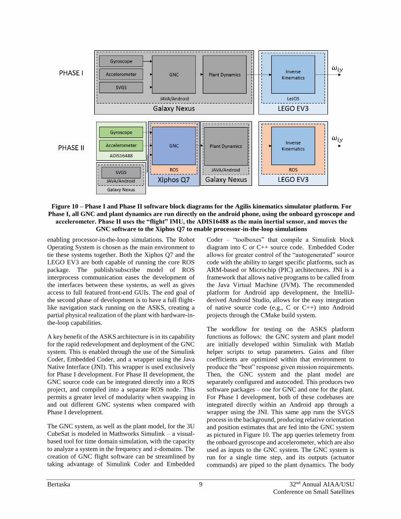
SOFTWARE ARCHITECTURE
Software Architecture
Software development is scheduled in two major phases,
as shown in Figure 10. In Phase I, the onboard gyroscope
and accelerometer of the Galaxy Nexus is used for
feedback, and the GNC algorithms are run from within
the phone, alongside the plant dynamics. This is all
programmed within a Java/Android environment. The
EV3 “brick,” the microcontroller regulating the motors
and communicating with the Galaxy Nexus, runs the
“LeJOS” operating system – an alternative, Java-based
OS developed by the LEGO community. During Phase I
development, the only necessary piece of hardware is the
SVGS compatible phone – all sensors and simulation
suites are hosted on it.
For Phase II development, the navigation stack is
integrated onto Agilis platform as modeled in Figure 2.
This allows for the “flight” IMU, the ADIS16488, to be
used for feedback in the control system, as well as
Figure 9 – SVGS target pattern configuration using
retroreflective cubes, with the center cube out of
plane. The target frame is denoted in blue.
Bertaska 9 32nd Annual AIAA/USU
Conference on Small Satellites
enabling processor-in-the-loop simulations. The Robot
Operating System is chosen as the main environment to
tie these systems together. Both the Xiphos Q7 and the
LEGO EV3 are both capable of running the core ROS
package. The publish/subscribe model of ROS
interprocess communication eases the development of
the interfaces between these systems, as well as gives
access to full featured front-end GUIs. The end goal of
the second phase of development is to have a full flight-
like navigation stack running on the ASKS, creating a
partial physical realization of the plant with hardware-in-
the-loop capabilities.
A key benefit of the ASKS architecture is in its capability
for the rapid redevelopment and deployment of the GNC
system. This is enabled through the use of the Simulink
Coder, Embedded Coder, and a wrapper using the Java
Native Interface (JNI). This wrapper is used exclusively
for Phase I development. For Phase II development, the
GNC source code can be integrated directly into a ROS
project, and compiled into a separate ROS node. This
permits a greater level of modularity when swapping in
and out different GNC systems when compared with
Phase I development.
The GNC system, as well as the plant model, for the 3U
CubeSat is modeled in Mathworks Simulink – a visual-
based tool for time domain simulation, with the capacity
to analyze a system in the frequency and 𝑠-domains. The
creation of GNC flight software can be streamlined by
taking advantage of Simulink Coder and Embedded
Coder – “toolboxes” that compile a Simulink block
diagram into C or C++ source code. Embedded Coder
allows for greater control of the “autogenerated” source
code with the ability to target specific platforms, such as
ARM-based or Microchip (PIC) architectures. JNI is a
framework that allows native programs to be called from
the Java Virtual Machine (JVM). The recommended
platform for Android app development, the IntelliJ-
derived Android Studio, allows for the easy integration
of native source code (e.g., C or C++) into Android
projects through the CMake build system.
The workflow for testing on the ASKS platform
functions as follows: the GNC system and plant model
are initially developed within Simulink with Matlab
helper scripts to setup parameters. Gains and filter
coefficients are optimized within that environment to
produce the “best” response given mission requirements.
Then, the GNC system and the plant model are
separately configured and autocoded. This produces two
software packages – one for GNC and one for the plant.
For Phase I development, both of these codebases are
integrated directly within an Android app through a
wrapper using the JNI. This same app runs the SVGS
process in the background, producing relative orientation
and position estimates that are fed into the GNC system
as pictured in Figure 10. The app queries telemetry from
the onboard gyroscope and accelerometer, which are also
used as inputs to the GNC system. The GNC system is
run for a single time step, and its outputs (actuator
commands) are piped to the plant dynamics. The body
Figure 10 – Phase I and Phase II software block diagrams for the Agilis kinematics simulator platform. For
Phase I, all GNC and plant dynamics are run directly on the android phone, using the onboard gyroscope and
accelerometer. Phase II uses the “flight” IMU, the ADIS16488 as the main inertial sensor, and moves the
GNC software to the Xiphos Q7 to enable processor-in-the-loop simulations
Bertaska 10 32nd Annual AIAA/USU
Conference on Small Satellites
velocities 𝑢 and 𝑣 and rotation rate 𝜔𝑧 are then converted
to ASKS wheel velocities 𝜔𝑖𝑦 . These are then sent as
motor commands to the EV3 “brick” motor controller.
The simulated 3DOF platform can now be run and its
response logged. Depending on the performance during
the experiment, the GNC system can be easily updated
simply by tweaking parameters, or if a structural change
is needed (e.g., increasing the order of a filter, adding a
gain in path where one was not included, etc.), the GNC
system can be autocoded and deployed to the Android
app. The latter typically takes less than five minutes to
go from a Simulink block diagram to an application
running on the ASK.
Robot Operating System
The Robot Operating System (ROS) provides a flexible
framework to create an autonomous system/robotic
middle layer on top of an operating system9. It handles
message passing (on a centralized publisher/subscriber
model) and comes bundled with package control. Many
features are available “out-of-the-box” through ROS
packages, such as Kalman filter implementations and
visualization software. ROS is compatible with a variety
of popular platforms including the Microsoft Kinect, a
three dimensional camera originally designed for the
Microsoft Xbox 360, and the Beaglebone Black, a
single-board computer that is popular in the hobbyist
community. ROS has been applied to differing platforms
in radically different environments, including personal
robotics9, marine vehicles10, intravehicular robotics on
the International Space Station11.
One important distinction is that ROS is not a real-time
operating system (RTOS), nor is it out-of-the-box
compatible with other RTOS, such as FreeRTOS and
VxWorks. However, ROS does excel at ease of use, with
a large online community and easily available tutorials.
It has been the experience of the authors that real-time
programming has a relatively steep learning curve for
students unfamiliar with RTOS concepts (e.g., tasking,
priority levels, semaphores, etc.). Transitioning the
software architecture from RTOS to ROS-based
significantly decreased the learning curve from 4-6
weeks to 1-2 weeks. Additionally, the availability of
ROS sample code further streamlined development in
later stages, as students could modify existing code
rather than reproduce it wholesale.
Language implementation is equally as important. ROS
is available both in C++ and Python. RTOS are typically
only available in C and C++, since both of these
languages compile down to native machine code rather
than rely on a non-deterministic virtual machine. It has
been the authors’ experience that engineering students
across all levels have a greater familiarization with the
Python language when compared to C, and especially
C++.
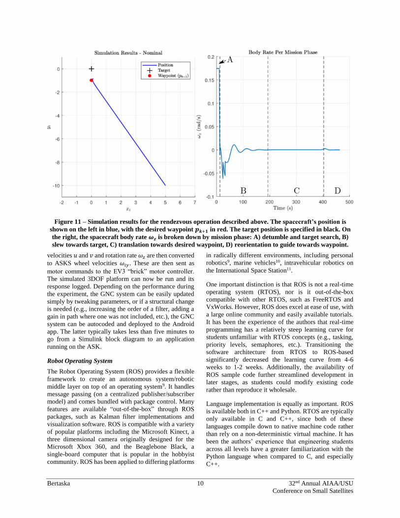
Figure 11 – Simulation results for the rendezvous operation described above. The spacecraft’s position is
shown on the left in blue, with the desired waypoint 𝒑𝒌+𝟏 in red. The target position is specified in black. On
the right, the spacecraft body rate 𝝎𝒛 is broken down by mission phase: A) detumble and target search, B)
slew towards target, C) translation towards desired waypoint, D) reorientation to guide towards waypoint.

Bertaska 11 32nd Annual AIAA/USU
Conference on Small Satellites
SIMULATION AND EXPERIMENTAL RESULTS
Simulation Results
Simulations of the autonomous rendezvous procedure
were produced using the Matlab/Simulink software suite
from Mathworks. The SVGS target frame was taken to
be coincident with the inertial frame, i.e., the spacecraft
started the simulation at an arbitrary point in the mission
area and then was guided towards the origin to perform
a proximity operation.
The simulation tasked the vehicle to perform four
separate tasks in order:
1. Detumble from an initial tip-off rate.
2. Perform a target search.
3. Slew towards the target.
4. Translate to a meter in front of the target.
The results presented here set an initial tip off rate at
10deg/s, and positioned the spacecraft 5m and -10m
from the target in the X and Y axis, respectively. The
mission area of this simulation roughly fits the footprint
of the portion of the flat-floor facility at Marshall Space
Flight Center that is dedicated for small satellite testing.
A desired “waypoint” was set -1m from the target in the
Y axis.
Results show the spacecraft successfully detumbling
utilizing the RCS thrusters, and proceeding towards a
target search, finally homing in on the target at roughly
~25deg. For the latter maneuver, the mode controller
switched the system to reaction wheel control. The
spacecraft then translated toward the desired waypoint
utilizing the Enclosure Based Steering guidance law.
Once the SVGS was able to produce an attitude solution,
a path was created between the current position (𝑝𝑘) to
the desired waypoint (𝑝𝑘+1). The spacecraft then
translated to approximately one meter in front of the
target before the simulation completed successfully.
A strength of Enclosure Based Steering is its ability to
compensate for outside disturbances. Simulation results
from the Simulink model are displayed for a spacecraft
with a faulted thruster, where an RCS thruster was
misaligned by 10 degrees from the nominal orientation.
A comparison between the cross track error during
translation for an Enclosure Based Steering guidance law
versus a simple LOS law,
𝜓𝑑 = −𝑎𝑡𝑎𝑛2 [𝑥𝑘+1−𝑥
𝑦𝑘+1−𝑦], (35)
is presented in Figure 12. It can be readily seen that the
Enclosure Based Steering approach was able to bring the
vehicle back to the desired path, whereas the pure LOS
guidance failed to do so, incurring a cross track of up to
0.7m.
Experimental Results
Experimental results are presented for a subset of the
tasks described in the previous section. The experiment
focused exclusively on “detumbling” the satellite, then
slewing towards the target, and performing an attitude
hold for a set duration of time (tasks 1-3 as described
previously). This is analogous to a spacecraft detumbling
after ejection, followed by moving into a stable pointing
orientation (e.g., a solar inertial hold, or relative hold on
a target). The ASKS was outfitted with the “Phase I”
avionics architecture depicted in Figure 10 to perform
these experiments.
The ASKS platform was placed approximately one
meter away from the target at a slight offset of 2cm. For
this series of tests, the accelerometer was disabled, and
the position output was directly taken from the SVGS. If
the SVGS failed to find a solution, the last valid solution
was latched. The attitude filter was similarly modified
where the SVGS attitude solution was taken to be the
attitude estimate of the system without fusing gyroscope
measurements. If the SVGS was not able to produce an
attitude solution, the filter would then propagate the
attitude estimate using the body rate measurements.
Figure 12 – Comparison of cross track errors 𝚫𝒆
between the Enclosure Based Steering and LOS
guidance steering laws.

Bertaska 12 32nd Annual AIAA/USU
Conference on Small Satellites
Figure 13 presents the results from experimental test.
The figure on the left displays the commanded attitude
𝜓𝑑 in blue and the estimated attitude �̂� in red. On the
right, there is a comparison between the simulated plant
rate 𝜔𝑧, the unfiltered ASKS platform IMU rate (gray),
and the filtered IMU rate (black). The three main phases
are demarked in each figure by the vertical dashed line:
the detumble phase (A), the slewing maneuver (B), and
the “hold and point” maneuver (C). The system utilizes
a bang-bang controller with the RCS for the detumble
phase, and a fine pointing reaction wheel control for the
remainder of the phases. Examining both figures, it is
clear that the kinematic simulator platform detumbled
successful, with the rotation rate of the platform
dropping to zero for both the simulated plant and ASKS
IMU. It is noteworthy that the filtered IMU signal closely
matched that of the simulated plant output, signifying
that the inverse kinematic operation from the spacecraft
body velocities and rate to Agilis wheel velocities was
successful. The remainder of the experiment continued
to be successful in this regard, with the sensed rate of the
ASKS platform closely trending with the simulated plant
output. In the second phase, the system was tasked to
perform a slew towards the target. A desired orientation
𝜓𝑑 was constructed from the estimated position of the
ASKS to the a priori target position such that the SVGS
would acquire a successful solution. A position solution
was first obtained during the detumble operation, where
the target passed in the line of sight of the SVGS. This
solution was then maintained during the slewing
maneuver, which did not have the successful lock on the
target until the 45s mark. A noticeable drift then occurred
in the desired attitude signal as the SVGS reacquired a
lock on the target and produced an updated attitude and
position solution. The remainder of the mission
demonstrates a successful attitude hold maneuver with
the SVGS maintaining the target in its sights. The reader
may note a small offset between the desired orientation
and the estimated orientation. This is the result of two
main causes. The first is due to a quantization effect
when requesting a wheel velocity from the LEGO EV3
controller. During phase C), the steady state error was
not large enough to overcome this quantization given the
gains on the RWA PD controller. For this particular run,
the integral gain 𝐾𝑖 was disabled for the RWA controller,
which did not allow the steady state error to accumulate
over time. This would have built up a control signal large
enough to dominate the quantization. As part of a
redesign of the ASKS platform, the gearing ratio will be
stepped down such that a larger motor command will
produce a lower wheel speed, allowing for finer control
of the platform.
EDUCATIONAL OUTREACH
A variety of students with varying skill sets have
contributed to this project. These have spanned the
academic spectrum from high school seniors to graduate
students. The authors serve only as system integrators
Figure 13 – Results from the experimental test with the ASKS performing a detumble (A), slew (B), and hold
and point (C) maneuvers. The desired attitude 𝝍𝒅 (blue) is compared against the estimated attitude �̂� (red)
from the attitude filter on the left. The right displays the simulated plant rotation rate (blue), the unfiltered
IMU rate from the ASKS platform (gray) and the filtered rate signal (black).

Bertaska 13 32nd Annual AIAA/USU
Conference on Small Satellites
and mentors – the majority of the development of this
project has been contributed by students, interns, and
volunteers. The following section relays the experience
of the authors’ in working with these students. It is not
intended to be an impartial assessment, but rather, is a
series of best practices that the authors’ have found to be
successful.
The multidisciplinary aspects of the ASKS platform are
used to its advantage. A range of disciplines are used to
create the platform, which allows mentors to select the
strengths of each student and direct them to develop
along that particular path. These disciplines are broken
down across the columns of Table 1 – mechanical
design, avionics and software, GNC, and SVGS
development. The rows give the educational level of
each student and tasks that he or she is likely best suited
for.
Through educational outreach programs in public
schools, high school students have worked on ASKS
development. These students are high performing, but
have only had a fraction of the courses taught in a college
engineering program. However, traditional high school
engineering curriculums stress computer aided design
(CAD). With the advent of low-cost 3D printers, students
now have the complete experience of designing a part
and manufacturing a prototype. This experience is
leveraged in this project where students are given
requirements for a single part, and must deliver a
prototype by the end of their rotation. This gives a
“hands on” introduction to the engineering development
cycle. These students often have some experience in
calculus and basic linear algebra, but typically have not
had an opportunity to use it in practice. The ASKS
platform serves as a test bed for this purpose. Concepts
such as integration and derivation (through the vehicle
acceleration, velocity, and position), matrix inversion
(through the inverse kinematic relation in (18) and (19))
and gear ratios are given a physical anchor. The selection
of Java as one of the main languages for this project
leverages its continued use in Advanced Placement
computer science courses, as well as its popularity in
Introduction to Computer Science and object-oriented
programming courses. Although high school students
may not have the skillset to make significant
development in the codebase, they can make small
modifications to deploy different concepts. The use of
LEGO robots and cellular phones creates an
approachable environment where students are familiar
with the toolset, creating a launch point for furthering
their knowledge of small satellites and general
engineering.
Students further along in academic level, like later
college or early graduate school, get introduced to
concepts that are more specified. These include image
processing, computer vision, Kalman filters, and control
systems. The latter two are especially important as many
engineering curriculums do not focus heavily on GNC,
and may not sufficiently bridge the gap between theory
and practice. Students may have some familiarization
with concepts like PID controllers and linear filters, but
have not had the opportunity to exercise them in a design
environment. The ASKS provides this opportunity with
its ability to rapidly redeploy the entire GNC system.
Upper level students have contributed to this program in
terms of software development both on the avionics
platforms and the SVGS, as well as implementation of
controllers and mission planners for wheeled vehicles.
Students of all levels have contributed to this project as
described below:
Design of mechanical interfaces and mounts
between the navigation stack and the Agilis
robot.
Design of mechanical interfaces between the
SVGS phone and target and the Agilis robot.
Construction and implementation of PID
controllers and mission planners for wheeled
vehicles and CubeSats.
Construction and implementation of navigation
filters using an extended Kalman filter for
position estimation on wheeled vehicles and
CubeSats.
Low-level device drivers for Linux systems
wrapped in ROS nodes.
Software architecture design in the ROS
environment for the GNC system
Processor-in-the-loop testing of the Xiphos Q7
with the GNC system in a ROS environment.
Development of graphical user interfaces to log
telemetry and display telemetry from the
ASKS/CubeSat system.
Extension of the SVGS blob tracking algorithm
to work with colored LEDS in addition to
retroreflective targets.
Refactoring and documentation of SVGS
software.
Development of interfaces between LEGO
EV3 “brick” and Android smartphone.
A diversity of “soft skills” have also been introduced as
part of this project. These skills apply in breadth of fields
and range from professional writing, mentoring, as well
as configuration management. Concepts such as
interface control documents are introduced such that
each students work can be taken to be a “black box” that
interfaces with the rest of the system.

Bertaska 14 32nd Annual AIAA/USU
Conference on Small Satellites
Internships at NASA range anywhere from 12 weeks in
the Summer semester to 16 weeks in Fall and Spring
Semesters. The key challenge is identifying a deliverable
that each student is capable of producing within that
time. There is no systematic process in assigning a
student tasks – it has been the authors’ experience that
one-on-one mentorship provides the best results for both
parties. Mentors are better able to grasp the strengths of
each student and assist them where necessary, and
students are able to work on projects that align with their
proficiencies.
CONCLUSION
An alternative to “floating” CubeSat systems mounted
on air bearings is given here, where the kinematics of the
system can be represented by the motion of an
omnidirectional wheeled vehicle equipped with
rotacaster wheels. Plant dynamics are simulated within
the wheeled robot to produce velocities and body rates.
This allows the engineer to test high level guidance and
navigation algorithms without the overhead of the
traditional air-bearing method, which may be limited by
mission area or length of air supply hoses. An
omnidirectional robot is constructed out of LEGO EV3
parts and equipped with a smartphone-based relative
navigation sensor, the SVGS, making it accessible as an
educational platform. Multiple ASKS units may be
constructed to simulate complex multi-satellite mission.
The ASKS platform is detailed with a derivation of the
inverse kinematic solution from 3DOF planar body
velocities and rate to wheel speeds. Two separate control
laws are given – a phase plane controller focusing on the
translational and coarse attitude control using a cold-gas
RCS, and a PID controller for fine pointing control using
reaction wheels. Due to the underactuation of the 3U
CubeSat system the ASKS platform was based on, an
Enclosure Based Steering approach is given to direct the
vehicle back to a path between waypoints during
translational control. Simulation and experimental
results are presented of the 3U CubeSat and the ASKS
platform operating in a proximity operation-like
scenario. It was shown that the ASKS was able to
successfully replicate detumble, slew, and attitude hold
maneuvers of the 3U CubeSat.
Forward Work
The system can be further improved in modeling the
3DOF planar motion of a satellite by increasing the
gearing ratio between the motor and the wheels. For slow
slews, as would be expected on a small satellite platform
with small reaction wheels, a greater control of the
position of each wheel of the Agilis is necessary. The
authors’ noticed some limit cycle oscillations driven by
quantization effects of the wheel controller on the EV3
robot. A smaller gearing ratio would allow a greater
range of motion of each motor, reducing the impact of
quantization.
The construction of multiple units allows for simulation
of complex proximity operation missions and formation
flying. This creates an easy to use platform for students,
interns, and young engineers that enables the simulation
Table 1 – Recommended roles and responsibilities for a multidisciplinary project given a students’ level of
education and experience.
Academic Level
Mechanical Design Avionics and Software GNC SVGS
High School CAD’ing simple geometries, 3D printing
parts, assembly and integration of systems
Introduction to Ohm’s law, power calculation, polarity.
Java programming introduction.
Basic linear algebra introduction (e.g.,
determinants, matrix inversions).
Operation of SVGS.
Early College
(Freshmen And Sophomores)
Advanced CAD’ing,
coordination with high school interns for 3D
printing.
Debugging of avionics
interfaces, simple input/output programming.
Basic Java programming.
Updating UI of SVGS.
Late College
(Juniors And Seniors)
- Integration of GNC project
into ROS. Wrapping FC hardware drivers into ROS
nodes. Processor-in-the-
loop and hardware-in-the-loop simulations.
Designing of Kalman
filters, redesign of control system gains, advanced
mission planning
(trajectory planning), integration of A* planner.
Enhancement of capabilities
of SVGS outside of core engine (e.g., different blob
tracking algorithms,
optimizing implementation).
Graduate - -

Bertaska 15 32nd Annual AIAA/USU
Conference on Small Satellites
and testing of collaborative multi-satellite scenarios with
familiar components.
Acknowledgements
The authors would like to thank the following students
for their contribution this work: Zachary Prihoda, Elijah
Johnson, Amarri Cole, Tevon Walker, Eric Bradshaw,
Dylan Hunziker, Chris Carter, Logan Bolingbroke, Zakk
Giacometti, Brian Adams, James Holt, Bryce Brown,
and Joshua Bryant. A special thanks to Devon Sanders
for his support in the initial phases of this project.
REFERENCES
1. C. Becker, R. Howard and J. Rakoczy,
"Smartphone Video Guidance Sensor for Small
Satellites," in 27th Annual AIAA/USU Conference
on Small Satellites, Logan, Utah, USA, 2013.
2. F. Terui, "Position and attitude control of a
spacecraft by sliding mode," in American Control
Conference, Proceedings of, Philadelphia,
Pennsylvania, USA, 1998.
3. J. E. Prussing and B. A. Conway, Orbital
Mechanics, New York City, New York, USA:
Oxford University Press, 1993.
4. D. Garcia-Sillas, E. Gorrostieta-Hurtado, J. Vargas,
J. Rodriguez-Resendiz and S. Tovar, "Kinematics
modeling and simulation of an autonomous omni-
directional mobile robot," Ingeniera e
Investigacion, vol. 35, no. 2, pp. 74-79, 2015.
5. J. L. Crassidis and J. L. Junkin, Optimal estimation
of dynamics systems, CRC Press, 2011.
6. T. I. Fossen, Handbook of marine craft
hydrodynamics and motion control, John Wiley &
Sons, 2011.
7. F. H. Moffit and E. M. Mikhail, Photogammetry,
New York City, New York, USA: Harper & Row
Inc., 1980.
8. J. Rakoczy, Application of the photogrammetric
collinearity equations to the orbtial express
advanced video guidance sensor six degrees-of-
freedom solution, MArshall Space Flight Center,
AL: NASA Internal memo #XD-31-(-05-004),
2005.
9. M. Quigley, K. Conley, B. Gerkey, J. Faust, T.
Foote, J. Leibs, R. Weeler and A. Y. Ng, "ROS: an
open-source Robot Operating System," ICRA
workshop on open source software, vol. 3, no. 3.2,
p. 5, 2009.
10. J. Wampler, T. Mosciki and K. von Ellenrieder,
"Towards adjustable autonomy for human-roboit
interaction in marine systems," in OCEANS 2017 -
Aberdeen, Aberdeen, Scotland, UK, 2017.
11. J. Yoo, I.-W. Park, V. To, J. Q. Lum and T. Smith,
"Avionics and Perching Systems of Free-Flying," in
AIAA SPACE 2015 Conference and Exposition,
Systems Engineering (ISSE), 2015 IEEE
International Symposium on, 2015.