Embed Size (px)
Citation preview

R. G. Sparber October 31, 2015 Page 1 of 15
An Improved Tool Support for a Harbor Freight
® Tool
Grinder, version 2.2 By R. G. Sparber
Copyleft protects this document.1
Advisory This article was written with a hobby machinist a bit
above novice in mind. Someone new to our hobby may
have trouble following along. If you do, please don’t
hesitate to contact me with your questions.
The tool support that
came with my 1/2 HP 6" Tool Grinder enables me to
grind any included angle from 90° to 180°2. That
means that shaping a thread cutter with an included
angle of 60° is a problem. I need to put this type of
cutter perpendicular to the compound. Then I can
grind any included angle from 0° to 90°.
One fix for this problem is to add a right angle
support. This does work but now I have to keep the
right angle pressed against both the tool support
and the cutter at the same time. There must be a
better way.
1 You are free to copy and distribute this document but not change it.
2 See the appendix for details.

R. G. Sparber October 31, 2015 Page 2 of 15
My new tool support solves
this problem.
My tool support can be set
from -30° to +90°.
To form a 60º included
angle, grind the left face
with the compound as
shown.
I grind the other face of the
cutter with the compound
set to +30° and flip the
base around so the clamp is
in front.

R. G. Sparber October 31, 2015 Page 3 of 15
I have chosen to just put a
few numbers on the
compound for rough
alignment.
The exact
angle should
be set with a
gage pressed
up against the
grinding
wheel and the
flank of the
compound.
The surface
of the wheel
must be
dressed flat.

R. G. Sparber October 31, 2015 Page 4 of 15
Another problem with the original tool support is typical of such a low cost
machine - poor fit of the slider in the table. Fortunately, I found the slot to be of
uniform width so only the tool support needed to be replaced.
The tool support is made from four parts: the
slider, the pivot, the clamp, and the
compound. Not shown are two 8-32 Socket
Head Cap Screws.

R. G. Sparber October 31, 2015 Page 5 of 15
The Slider Before making the slider, measure the width of the table slot. You need a nice,
sliding fit. Also measure the depth of the slot. The slider should not touch the
bottom of the slot. Adjust the design as necessary.
Shop Procedure 1. cut bar to 4.1"
2. mill 0.05" from one end
3. mill step 0.05" deep by 0.1" wide
4. mill overall length to 4.00"
5. drill and ream 0.281" hole
6. drill with #29 and tap 8-32 hole
7. flip bar over and use reamer to align hole with the spindle
8. use 3/8" end mill to counterbore 0.375" hole to depth of 0.05"
9. measure width of bar
10. put bar on edge and mill off half the difference between bar width and slot width
11. flip bar over and mill second edge to slot width
12. trial fit to slot and file for sliding fit
13. deburr part
R. G. Sparber October 31, 2015 Page 6 of 15
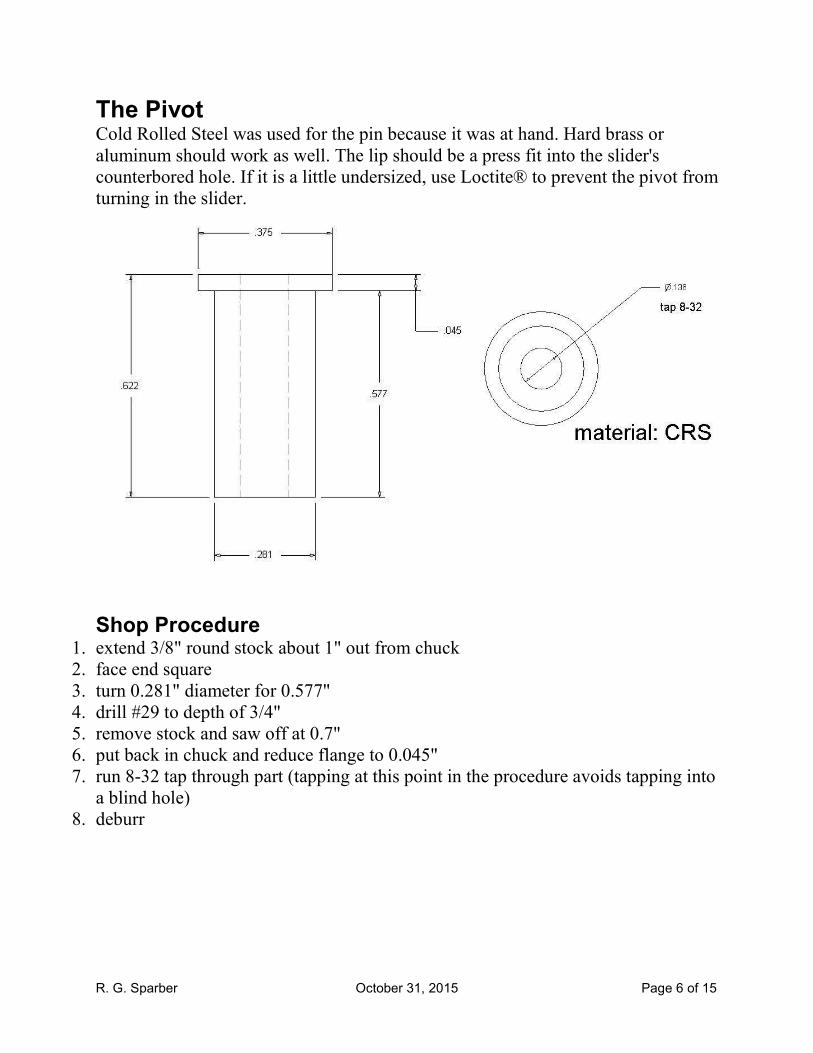
The Pivot Cold Rolled Steel was used for the pin because it was at hand. Hard brass or
aluminum should work as well. The lip should be a press fit into the slider's
counterbored hole. If it is a little undersized, use Loctite® to prevent the pivot from
turning in the slider.
Shop Procedure
1. extend 3/8" round stock about 1" out from chuck
2. face end square
3. turn 0.281" diameter for 0.577"
4. drill #29 to depth of 3/4"
5. remove stock and saw off at 0.7"
6. put back in chuck and reduce flange to 0.045"
7. run 8-32 tap through part (tapping at this point in the procedure avoids tapping into
a blind hole)
8. deburr

R. G. Sparber October 31, 2015 Page 7 of 15
The Clamp This part is tiny and so
can be difficult to clamp
during machining. One
solution is to machine
the end of a bar and
don't cut the part free
along the 0.330"
dimension until all other
surfaces have been
finished. I used a bar of
½" x ½" x 8" 6061
aluminum and cut the
part up-side-down.
Shop Procedure 1. layout clamp up-
side-down on end of ½"
x ½" bar that is at least a
few inches long
2. Side mill end
square
3. set end mill
0.340" from bottom of
bar and rough cut 0.7"
wide
4. set end mill 0.330" from bottom of bar and do finish cut
5. set end mill 0.190" from bottom of bar and rough cut leg 0.11" wide and cut
the underside of the horizontal at least 0.5" wide
6. set end mill 0.180" from bottom of bar and finish cut leg 0.100" wide
7. drill #17 clearance hole 0.350" from end
8. remove bar and rotate 90º so the side face is exposed
9. remove half of the difference between the bar's width and 0.460"
10. flip bar over and reduce the width of the clamp to 0.460"
11. remove bar and cut the clamp off leaving about 0.05"
12. mill the clamp to 0.600 long
13. file a slight curvature into the end of the clamp to fit a 2.8" diameter circle
14. deburr

R. G. Sparber October 31, 2015 Page 8 of 15
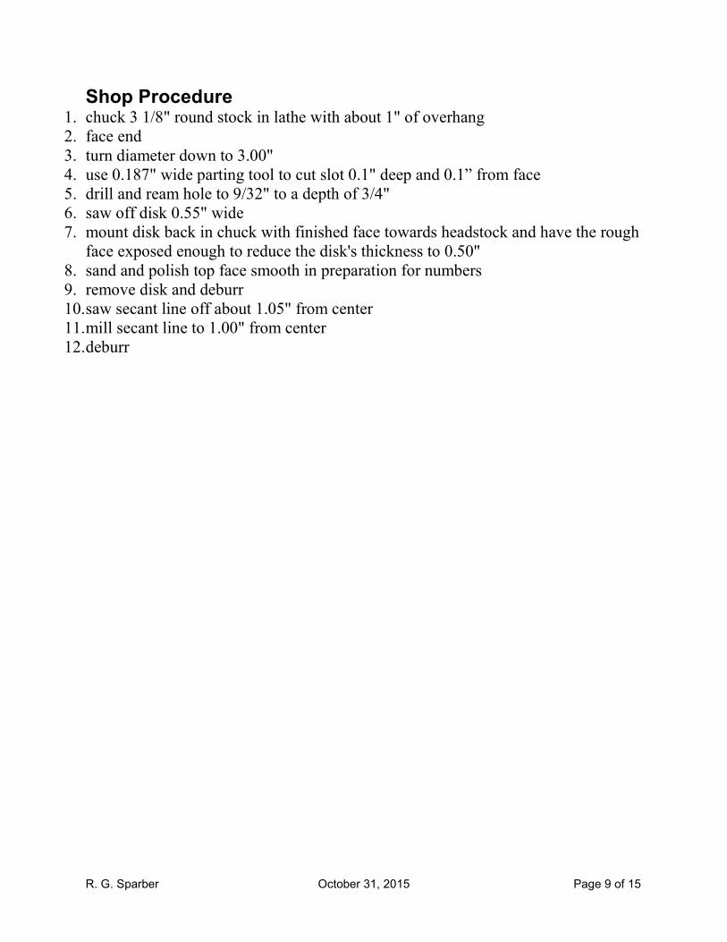
The Compound
I started with 3.125" diameter 12L14 steel. The width of the slot was set by my cut
off tool. If you change this dimension, change the clamp too. Similarly, the center
hole was set by the reamer I had at hand. You could use a 1/4" to 5/16" reamer. Be
sure to change the pivot pin to match.
R. G. Sparber October 31, 2015 Page 9 of 15
Shop Procedure 1. chuck 3 1/8" round stock in lathe with about 1" of overhang
2. face end
3. turn diameter down to 3.00"
4. use 0.187" wide parting tool to cut slot 0.1" deep and 0.1” from face
5. drill and ream hole to 9/32" to a depth of 3/4"
6. saw off disk 0.55" wide
7. mount disk back in chuck with finished face towards headstock and have the rough
face exposed enough to reduce the disk's thickness to 0.50"
8. sand and polish top face smooth in preparation for numbers
9. remove disk and deburr
10. saw secant line off about 1.05" from center
11. mill secant line to 1.00" from center
12. deburr

R. G. Sparber October 31, 2015 Page 10 of 15
The numbers on the
compound use my
Parchment Paper and
glue technique3. I start
by printing the artwork
on Parchment Paper
using my HP® laser
printer.
I print one right reading
copy to see how it
looks plus five mirror
image copies in case I
screw up the toner
transfer.
After coating the
surface of the
compound with
Loctite® Glass
Glue, I put down
the mirror image
artwork. It then set
for about fifteen
seconds before the
paper lifts off. The
Parchment Paper
lightly holds the
toner and the glue
holds it firmly.
3 See http://rick.sparber.org/ttm.pdf.

R. G. Sparber October 31, 2015 Page 11 of 15
With the glue fully cured, I spray
down a few coats of Rust-Oleum
Crystal Clear Enamel Spray®. The
solvent slightly melts the toner and
darkens it. The enamel protects the
toner.
You can see where the glue was put
down. Next time I plan to coat the
entire surface so there is no contrast
with the uncoated area.

R. G. Sparber October 31, 2015 Page 12 of 15
It is hard to tell in this picture, but the perimeter
of the compound is about 1/4" from the wheel.
I could have cut my secant line closer to the
pivot point but then I would not be able to turn
to -30º.
The step cut in the slider was intended to keep the clamp
from rotating. It did not work as well as hoped. So I coated
the bottom of the leg of the clamp in violin rosin. The
added friction did the trick.
Thanks to Tim Hofstetter for reminding me that the wheel must be dressed flat
before using the fish to set the angle of the guide. Thanks to Jerry Halcomb for
pointing out that a am referring to a secant line here and not a secant (as in
function).
I welcome your comments and questions.
Rick Sparber

R. G. Sparber October 31, 2015 Page 13 of 15
Appendix It may not be obvious why the compound that comes with the grinder is limited to
an included angle of 90° to 180°. Here is my attempt to explain it.
With the compound set to 0°, the cutter
blank has the end ground square. This is an
included angle of 180° as will hopefully
become apparent soon.
I can swing the compound over to -45° and cut
on the right side of the cutter. It cannot be
turned more than this.

R. G. Sparber October 31, 2015 Page 14 of 15
I can then rotate the compound to +45° and
grind the left face of the cutter. I cannot
rotate more than this angle.
The resulting cutter has an included angle
of 90°. Note that the compound’s angle is
measured from a line perpendicular to the
center line of the cutter blank. Yet we
usually talk about the angles on a cutter
with respect to this center line.

R. G. Sparber October 31, 2015 Page 15 of 15
If I turned the compound to
26.4° and ground both sides of
the cutter, I would get an
included angle of
180° - 26.4° -26.4° = 127.3°.
The trend here is that the smaller the compound angle,
the larger the included angle. This is why a compound
angle of 0° causes an included angle of
180° - 0° - 0° = 180°.
Given that a threading tool needs an included angle of 60°, the compound that
comes with the grinder would have to turn to +/- 60° yet can’t get past +/- 45°.
Now, if I put the cutter on end and support it with
a right angle, I can get to +/- 60° by setting the
compound at +/- 30°.


![93816[1] Harbor Freight](https://img.pdfslide.net/doc/110x75/5525e1174a7959e6488b4dd1/938161-harbor-freight.jpg)