Embed Size (px)
Citation preview

An Integrated Approach for Closing the Gaps Associated with Spent Nuclear Fuel Cladding Hydrides
Ken B. SorensonSandia National Laboratories
Brady D. HansonPacific Northwest National Laboratory
DSFM Reg Con 2016December 7th, 2016White Flint, Maryland
SAND2016-11903 C
2
Contents
Spent Fuel and Waste Science and Technology (FSWST;
formerly known as the Used Fuel Disposition program) storage and
transportation R&D program priorities
Technical progress to-date associated with meeting program objectives
Conclusions

3
SFWST ST R&DProgram Objectives
Storage and Transportation Program Objectives
Support the development of the technical bases:• to demonstrate used fuel integrity for extended storage periods• for fuel retrievability and transportation after long term storage• for transportation of high burnup fuel
This talk will focus on the development of the technical basisassociated with fuel cladding/hydride issues that have been identifiedas a high priority technical gap (2011, 2012, 2014 DOE gap analysis reports)
UFD Telecon, April 12, 2012
Billone, Liu; Argonne
UFD Telecon, April 12, 2012
Wagner, Adkins; ORNL
‘Jones 2010.ppt’,
Calvert Cliffs Dry Fuel Storage
and Industry Lessons Learned

4
U.S. High Burnup Fuel Inventory:What level of burnups are we discharging to dry storage?
Number of Assemblies Average burnup (GWd/MTU)
Year BWR PWR BWR PWR
2000 4603 3122 38.3 44.9
2001 3617 2896 40.1 45.5
2002 4148 3765 40.2 46.0
2003 4584 3585 39.5 46.4
2004 4431 2669 42.8 46.9
2005 4075 3704 42.8 46.6
2006 3995 3516 43.1 46.9
2007 4574 2782 43.3 46.9
2008 4480 3550 43.1 47.2
2009 4395 3677 45.1 46.5
2010 4617 2856 44.3 46.8
2011 4105 3663 45.1 46.6
2012 4476 3759 45.0 44.5
2013 3246 1534 44.1 45.4
High burnup defined as> 45 GWd/MTU
Over the past 15 yrs: >70% of discharged PWR SNF
is < 50 GWd/MTU Max discharge burnups do not
appear to be increasing[EPRI Fuel Reliability Database (FRED)]
Limits to much higher burnup: 5 w/o 235U enrichment Cycle length (18, 24 months in
US)
Moving from low burnup to high burnup is a continuum that needs to be put in proper context relative to: Total hydrogen content in clad Maximum fuel temperatures Internal rod plenum pressures
GC-859 Reported Average Assembly-Average Discharge Burnup
5
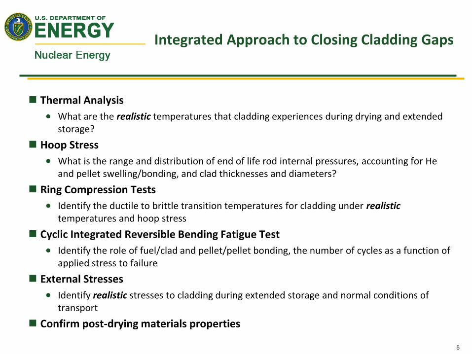
Integrated Approach to Closing Cladding Gaps
Thermal Analysis
What are the realistic temperatures that cladding experiences during drying and extended storage?
Hoop Stress
What is the range and distribution of end of life rod internal pressures, accounting for He and pellet swelling/bonding, and clad thicknesses and diameters?
Ring Compression Tests
Identify the ductile to brittle transition temperatures for cladding under realistictemperatures and hoop stress
Cyclic Integrated Reversible Bending Fatigue Test
Identify the role of fuel/clad and pellet/pellet bonding, the number of cycles as a function of applied stress to failure
External Stresses
Identify realistic stresses to cladding during extended storage and normal conditions of transport
Confirm post-drying materials properties

6
Thermal Analysis:Cladding temperatures are limited to < 400° Cduring drying and in dry storage; NRC ISG-11.3
Develop realistic thermal profiles
Remove conservative assumptions in thermal models
Use actual and realistic times for drying and transfer times
Actual, not design basis, decay heat loadings
Remove conservatisms in assembly decay heat calculations
Actual, not conservative, ambient conditions (assumed 100°F average)
Realistic temperatures expected to be well below the 400°C regulatory guidance
Used in numerous calculations for creep, He release, pressure calculations, etc.
Peak Cladding Temperature (°C)
with 36.8 kW heat load
Thermal analyses of DOE/EPRI dry
storage demo cask TN-32B with HBU PWR fuel
Peak Cladding Temperature (°C)
with 30.6 kW heat load
(same fuel)
7
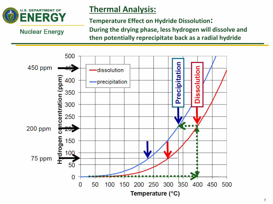
Thermal Analysis:Temperature Effect on Hydride Dissolution:During the drying phase, less hydrogen will dissolve and then potentially reprecipitate back as a radial hydride

8
Hoop Stress: FRAPCON analyses:Lower maximum cladding temperatures result in lower hoop stresses that, in turn, reduces precipitation of radial hydrides
Hoop stress is a function of
End of Life Rod Internal Pressure
– Initial He fill pressure
– Fission gas release
– Temperature
– Void volume
• Creep down/swelling
Clad inner diameter
Clad thickness (minus oxide layer)
FRAPCON predictions for Watts Bar Unit 1
rods discharged during Cycles 1-12 assuming
400°C peak clad temperature

9
Ring Compression Tests (RCT):RCT Results on HBU ZIRLO® provide indication of ductility as a function of temperature and H content
As-irradiated
HBU cladding
HBU cladding
After cooling from
400°C
Pictures from Billone,
NWTRB meeting, Feb 17, 2016
Picture from Billone,
FCRD-USED-2012-000039
10
Ring Compression Tests:Factors to consider
Need to be very careful when drawing conclusions based on limited data
Especially when many samples came from lead test assemblies or other “anomalous” sources that do not have typical total hydrogen content
Could be very applicable to European reactors with higher duty and higher burnup
Threshold of reorientation vs threshold of change in DBTT or material properties/performance
Caution when using literature values especially on unirradiated samples
Hydride reorientation a function of cladding type (chemistry?, grain orientation), total hydrogen content, hydride distribution (rim), RHT temperature, RHT/precipitation hoop stress
Given these cautions, trends look very positive that DBTT will not be an issue for HBU spent fuel under representative storage and normal conditions of transport environments
11
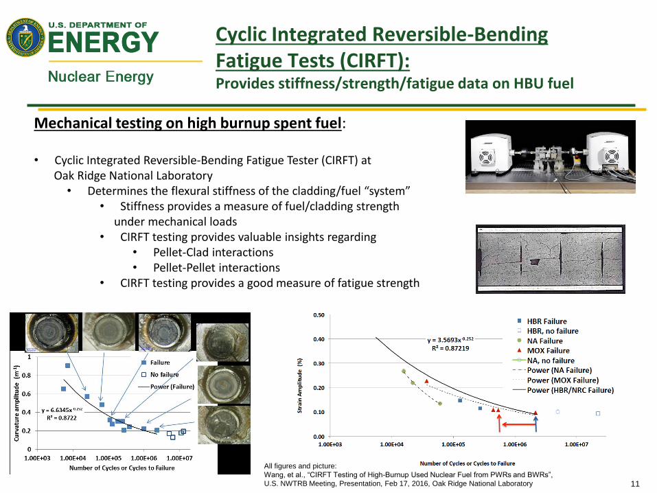
Cyclic Integrated Reversible-Bending Fatigue Tests (CIRFT):Provides stiffness/strength/fatigue data on HBU fuel
Mechanical testing on high burnup spent fuel:
• Cyclic Integrated Reversible-Bending Fatigue Tester (CIRFT) at Oak Ridge National Laboratory
• Determines the flexural stiffness of the cladding/fuel “system”• Stiffness provides a measure of fuel/cladding strength
under mechanical loads• CIRFT testing provides valuable insights regarding
• Pellet-Clad interactions• Pellet-Pellet interactions
• CIRFT testing provides a good measure of fatigue strength
All figures and picture:
Wang, et al., “CIRFT Testing of High-Burnup Used Nuclear Fuel from PWRs and BWRs”,
U.S. NWTRB Meeting, Presentation, Feb 17, 2016, Oak Ridge National Laboratory
12
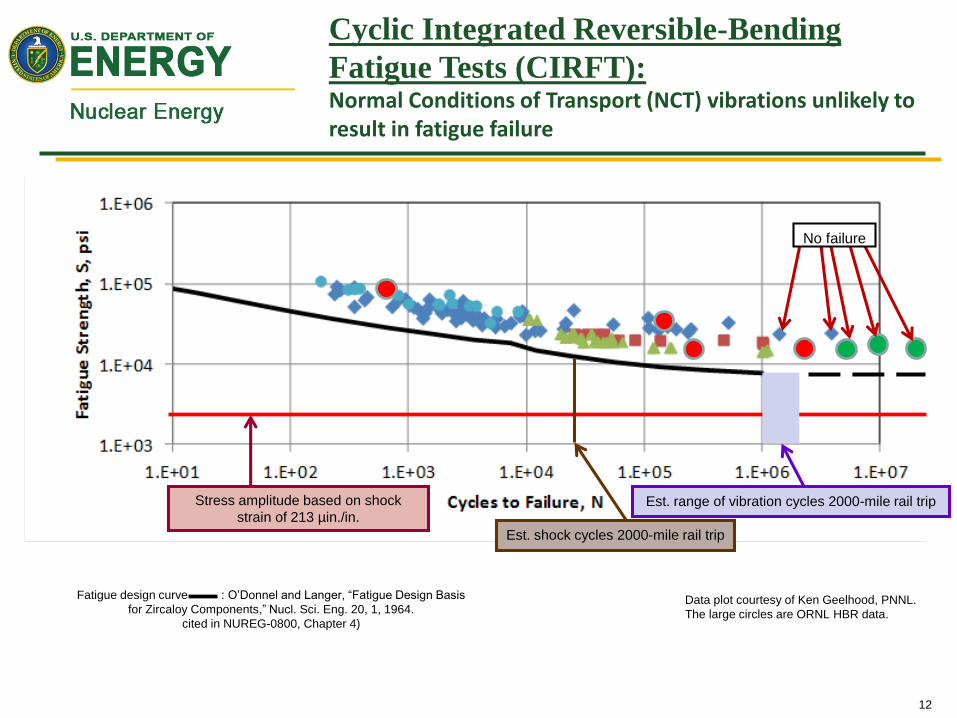
No failure
Stress amplitude based on shock
strain of 213 µin./in.
Est. shock cycles 2000-mile rail trip
Est. range of vibration cycles 2000-mile rail trip
Fatigue design curve : O’Donnel and Langer, “Fatigue Design Basis
for Zircaloy Components,” Nucl. Sci. Eng. 20, 1, 1964.
cited in NUREG-0800, Chapter 4)
Data plot courtesy of Ken Geelhood, PNNL.
The large circles are ORNL HBR data.
Cyclic Integrated Reversible-Bending
Fatigue Tests (CIRFT): Normal Conditions of Transport (NCT) vibrations unlikely to result in fatigue failure

13
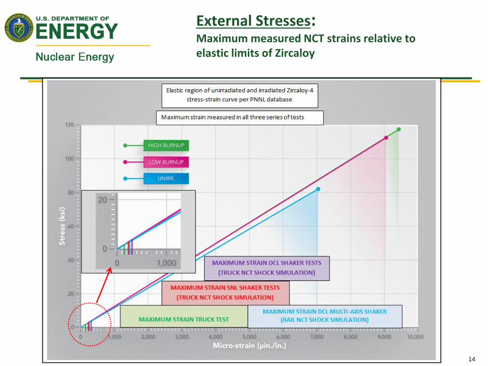
SNL Shaker2013
Over-the-Road Truck 2014
DCL Multi-Axis Shaker2015
Normal Conditions of Transport
TruckNormal Conditions of Transport
TruckNormal Conditions of Transport
Truck and Rail
External Stresses:Tests simulated normal conditions of transport loadings
on the fuel rods to measure strains on fuel rods in a
surrogate assembly
All tests used a surrogate PWR assembly which was placed within a surrogate truck-cask
basket.
The assembly and rods were instrumented with strain gauges and accelerometers.
14
External Stresses:Maximum measured NCT strains relative to elastic limits of Zircaloy
15
Conclusions
Hydride effects on spent fuel ductility
appear to be minimal in the context of
extended dry storage followed by
normal conditions of transport
This high priority technical gap, as identified
by numerous gap reports, has been effectively
addressed
An up-dated gap report will be issued by the
DOE in the spring of 2017, detailing this
conclusion