Embed Size (px)
Citation preview
2. AN OVERVIEW OF MINING GEOPHYSICS
Harold O. SeigelScintrex Limited, Concord, Ontario
Seigel, Harold 0., An overview of mining geophysics; in Geophysics and Geochemistry in the Searchfor Metallic Ores; Peter J. Hood, editor; Geological Survey of Canada, Economic Geology Report 31,p. 7-23, 1979.
Abstract
The technology of mining geophysics is advancing rapidly in methodology, instrumentation andinterpretation techniques. A surprising diversity of approach exists in a number of methods, becauseof differences in the local geological, geophysical, topographic or even socio-political setting.
A general trend is towards the simultaneous gathering of increasingly large amounts ofindependent geophysical data in airborne, ground or borehole surveys. The resultant challenge is toextract the maximum amount of useful geological information from the mass of field data generatedby these surveys. Increasingly, computers perform the task of routine interpretation, using eitherdirect inversion programs or automatic selection from a family of theoretical models.
Minicomputers are routinely employed in the control of multisensor airborne systems and in therecording of their output in digital form on magnetic tape. Some simple data manipulation is evenbeing done by such minicomputers in real time prior to recording.
Microprocessors are being increasingly incorporated into field portable geophysical instrumentsfor surface and borehole surveys.
Resume
L'application de la geophysique a l'extraction miniere connai't une evolution rapide tant auniveau de la methodologie et de l'instrumentation que des techniques d'interpretation. n existe desapproches etonnamment variees a certaines methodes a cause des differences sur les plansgeologique, geophysique, topographique ou meme socio-politique au niveau local.
De fagon generale, la geophysique tend a s'orienter vers la collecte simultanee d'une quantite deplus en plus grande de donnees geophysiques independantes recueillies par des leves aeriens, au sol oupar sondage. Le defi est alors d'extraire Ie plus grand nombre possible de donnees geologiques utilesde la masse de donnees obtenues par des leves sur Ie terrain. On fait de plus en plus appel auxordinateurs pour les taches d'interpretation courantes, en utilisant soit des programmes d'inversiondirecte ou de choix automatique a partir d'une famille de modeles theoriques.
On emploie couramment des mini-ordinateurs pour Ie controle des systemes aeroportes adetecteurs multiples et pour l'enregistrement des resultats obtenus sous forme numerique sur desrubans magnetiques. On utilise meme quelquefois ces mini-ordinateurs en temps reel lorsqu'il s'agitde manipulation simple de donnees, avant l'enregistrement.
De plus en plus, on incorpore les microprocesseurs aux appareils geophysiques transportablespour les leves en surface et par sondage.
INTRODUCTION
The science of geophysics applied to mineralexploration inclUdes a kaleidoscope of methods andtechniques, many of which are in a state of rapid flux. Atleast eighteen fundamentally different methods are in majoror minor use in mining geophysics around the world, somebeing employed in up to twenty variants.
There is a zestful difference of opinion on the relativemerits of methods, techniques and instrumental approaches,not only between the two main centres of development inNorth America and the U.S.S.R., but also among thesc.ientists in each centre. These differences of opinion have,through sc.ientific or commercial competition, beeninstrumental in stimulating advances in the art in bothcentres.
In my opinion, the most significant factor at present inmining geophysics is the data explosion. Through themiracles of 1977 microelectronics we can now endow a manor an aircraft with far more geophysical data gatheringcapability than would have been dreamed of only a few yearsago. For example, airborne radiometric systems record256 to 1024 channels of data simultaneously, whereas only ayear or two ago four channels were standard and ten years
ago only a single channel. Airborne electromagnetic systemstoday rarely gather fewer than six channels of data and manymore channels are contemplated. Ground inducedpolarization receivers commonly produce six channels of dataand one even makes one thousand channels available.Computer controlled data acquisition systems areincreasingly being used in airborne surveying as aremicroprocessors in ground based equipment, to facilitate thegathering and manipulation of multichannel data.
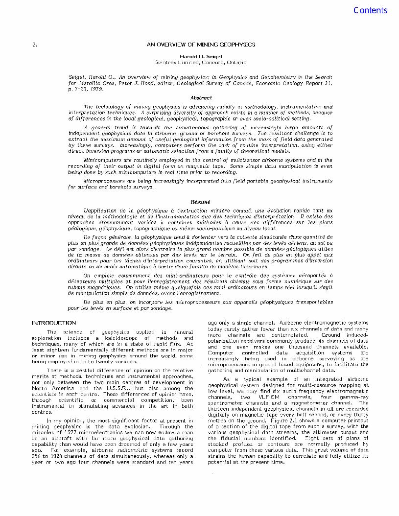
As a typical example of an integrated airbornegeophysical system designed for multi-resource mapping atlow level, we may find six audio frequency electromagneticchannels, two VLF EM channels, four gamma-rayspectrometer channels and a magnetometer channel. Thethirteen independent geophysical channels in all are recordeddigitally on magnetic tape every half second, or every thirtymetres on the ground. Figure 2.1 shows a computer printoutof a section of the digital tape from such a survey, with thevarious geophysical data streams, the altimeter output andthe fiducial numbers identified. Eight sets of plans ofstacked profiles or contours are normally produced bycomputer from these various data. This great volume of datastrains the human capability to correlate and fully utilize itspotential at the present time.
8 Harold O. Seigel
TRIDEM
1~3·8p.p.m. 1~3·4p.p.m. 1-;::: 24 p.p.m.
ALT. V.L.F.
REAL Q I Q 1 Q I QALT. = ~~=§==-~~~~=~,..,;:......:_R-SI8 V.L.F. 500Hz 2000Hz 8000Hz
RADIOMETRIC
, = O.K.0= OVERFLOW
COUNTS PER HALF SECOND0= X.II =XI.2 =X'D
TIMEFIDS
037~12ji0185814~11210181036117811811111111152152150A422.895m4489~28.88
0~7A12310235B14jI12102610251172117911111111520522.9642949'.99498520487
i~7112310285814511210191033119.1173111111115215224974324925~5489518487
0~711231~3358145112t037102811641180111111115195214954054B550148951649~
~0721231~3B~aI44112103010261170117911111111520522497375478.9649151B486
007212310435814511210321~2BI19511751!11111152~5215~0354468499488522490
0c.1312310485B1461121M291035117211861111111152~52250132945950249.524490
~~7)123ta535814Jlt21020102611811!82!111111152e.523.95318464504503523491
037d1231~5Bo8144112102910~~12021185111111115215224993~446b5~3493524491
0A741231053581431121028102Yl1771175111111115215224942994615074985214920~751231~685614JlI21032103411551181111111!15205294962994675~5506522.91
v~7512310735BI4411210311g31118~11821111111152~52249930~46551~50t527.910q75123t0765B14511210211031119011791111111151952249528647~502498520493
007512313B35814611210231~261193118611111111521523494271455501492519493
0~7712310885814411210271032116411851111111152052349a27045~49~4a9523490
~a77123109358145112102310361177118211111111519523501285446494487522488
a~7312310985614511210131~3211771181111111115195224942q0454494487521487
~~7512311~3561471121~2510291177117811111111519522494289457493487520489
0~7~12311~858!4S11210231~2311e3118111111111521522500276446491482525488
0~7912311135B145112102'1~31116311851111111152052249.272436488480519494
No. Hr. Min. Sec. I Digit :- . a:i ~m m [[]JI Gamma ~. m
i
Figure 2.1. Computer printout of typical multimethod airborne geophysical magnetic tape.(Courtesy Scintrex Limited)
In fact, the greatest challenge now facing mininggeophysicists is the distillation of the maximum amount ofuseful geological information from the mass of independentdata currently arising from surveys embodying single ormultiple methods. If this is to be done on a routine basis, itwill clearly have to be carried out by the computer.
Computer processing and machine presentations of datahave been already, of necessity, taken over from human handsand minds in the case of complex airborne-generated data ofthe type shown in Figure 2.1. Total "hands off" processing ofsuch data is still not practiced in most low-level surveys,however, because the flight path is still recovered usingtracking cameras due to the shortcomings of present radionavigational devices (such as Doppler). Navigational deviceswhich are moderate in cost, light enough to be used in therelatively small aircraft employed in mining geophysicalsurveys and still give the high positioning accuracyrequired (± 25 m) are not yet available. Transponder systems(e.g. Motorola, Raydist and Decca), using fixed stations, haveacceptable accuracy and weight but their cost andinconvenience precludes their general use.
The use of the computer has permitted somefundamental advances to be made in the quantitative interpretation of many types of geophysical data, particularly of amultichannel nature. The direct inversion of data forpurposes of interpretation is now practical in resistivity, IP(e.g. Pelton et al., 1977) and electromagnetic surveys (e.g.Sternberg, 1977). Where direct inversion is too demanding ofcomputer time, the computer still serves as a fast andeconomical means of selecting the best fi t from a family ofsimplified models for which it has derived the forwardsolution.
In order to provide a broad perspective on this complexfield and to place the various methods in their propercontext, I propose to structure this discussion by geologicalobjective. The broader features of each more importantmethod will be considered as it is encountered in its majorgeological application.
REGIONAL GEOLOGICAL MAPPING
In the field of basic geological mapping, the magnetometer remains the primary airborne geophysical tool,indicating the distribution of the various rock types andminerals through their variation in magnetic susceptibilityand remanent magnetization. However, the gamma-rayspectrometer is now almost a constant companion of themagnetometer for regional airborne geophysical surveys,providing a classification of rock or soil types based on theircontent of potassium, uranium and thorium.
A third mapping parameter, namely conductivity,utilizing one of several airborne electromagnetic devices isnow available. For this application, multiple frequencymeasurements or multichannel transient measurements arecommonly made in order to cover a broad range of earthconductivities.
Radio transmission measurements using VLF and broadcast band stations as source and measuring the ratio ofelectric and magnetic field components, can also map nearsurface conductivities. These are quantitatively discriminating only in a somewhat lower range of conductivities thanthose mentioned above since their basic operating frequenciesare high by normal airborne electromagnetic standards.
The Airborne Magnetometer
The proton magnetometer is the most commonly usedairborne magnetometer. In a stable, well-compensatedinstallation, the best of these can now achieve a usefulsensitivity of about 0.1 gamma (at one reading per second).Some high sensitivity (cesium, rubidium or helium) opticallypumped magnetometers are also being used for identificationof subtle features in areas of low magnetic activity and asvertical gradiometers.
Surprisingly enough, many total field self-orientingfluxgate magnetometers are still in operation, mostly in theEast, but also in the West because the smooth analog profiledata is still preferred by many interpreters.
...>- "'"wWL.. "'"
Mining Geophysics
240X • Plo:E[) Fll)..cll\l
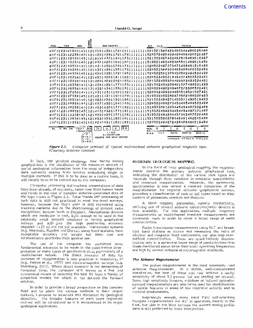
Figure 2.2. Computer plot of stacked airborne radiometric data in four channel profiles andelemental ratios. Pointe du Bois. Ontario. Canada. (Courtesy of Ontario Ministry of NaturalResources and Department of Energy. Mines and Resources. Ottawa).
9
10 Harold O. Seigel
/""<0---I--~--
/
DISTRIBUTION OF KNOWN LIGNITE DEPOSIT~ ~_CONDUCTIVITY CONTOUR INTERVALS ~__ IO milllmhos/metre
CONDUCTIVITY PEAK ~~_~ ~~ ~~~~ __ H
lkm
upward-looking crystal which is lead-shieldedfrom gamma radiation of terrestrial origin.Five hundred and twelve channels of gammaradiation may be similarly recorded from thisupward-looking crystal.
At least theoretically, the recording ofthe resulting 1024 channels of radiometricdata permits corrections for the effect ofatmospheric radon and cosmic radiation intothe natural terrestrial spectrum, rock-typeidentification through absolute levels ofuranium, thorium and potassium, as well astheir ratios, and an independent check on theenergy calibration of the gamma-ray spectrometer at all times. Some attempts are beingmade to recognize spectrum changes due tooverburden attenuation and soil moisturechanges, but with as yet uncertain success(e.g. Geodata, 1978).
The copious results of such multichannelsurveys cannot possibly be compiled andpresented in their entirety. In practice, theyare corrected for terrain clearance variations,cosmic and atmospheric background and thengrouped into four channels, one being "totalcount" and the other three centred about theprimary gamma peak for each of K, U and Th.Corrections are made for Compton interference of the elements so that three"stripped" elemental channels are presented,one for each of K, U and Th, as well as totalcount. These elemental channel values may bepresented directly, or as ratios, in profile orcontour form.
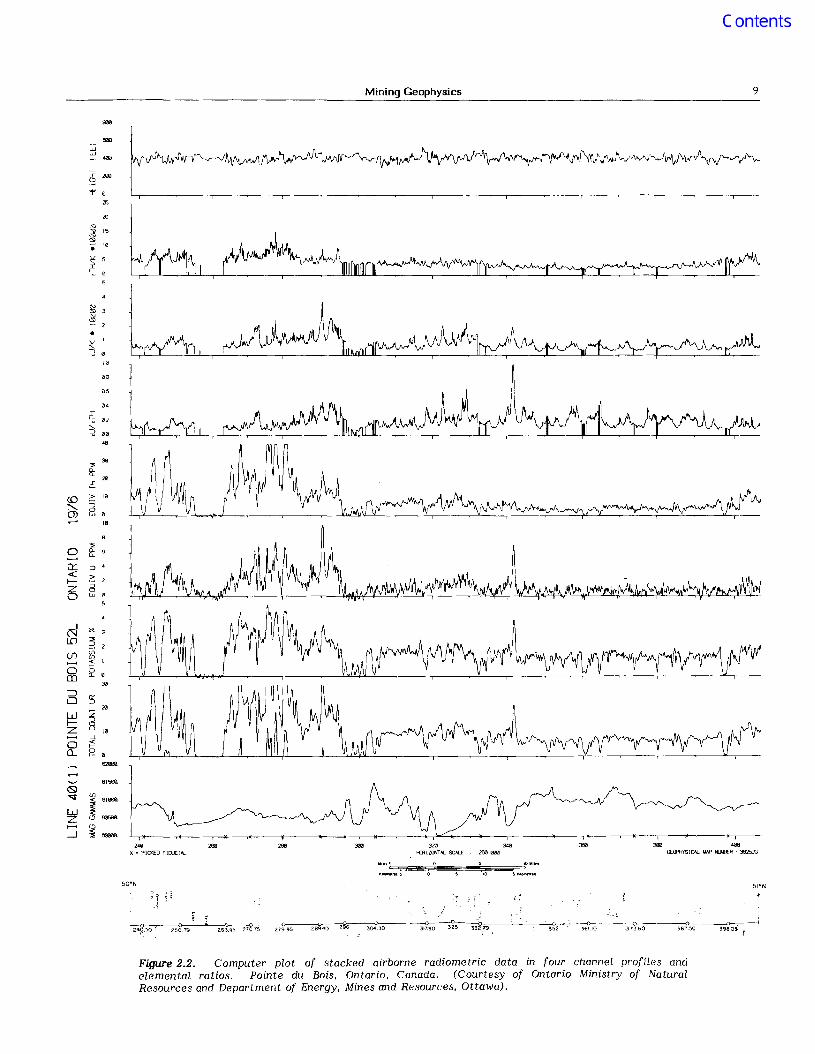
Figure 2.3. Computer interpretation of lower layer conductivity derivedfrom Tridem airborne electromagnetic data. Onakawana lignite deposit,Ontario. (Courtesy Ontario Ministry of Natural Resources)
Regional aeromagnetic surveys for mapping purposesare normally flown at a mean terrain clearance of about150 to 300 m (terrain permitting) and with line spacingsdepending on the ultimate plotting scale. For example, if theplotting scale is to be about 1:50 000 the line spacing may be500 m (or 0.25 mile) and for 1:100 000 the line spacing may be1 km (or 0.5 mile) etc. Surveys for specific explorationtargets will have line spacings dependent on the expectedtarget dimensions.
Compilation of the resultant aeromagnetic data, mostof which are now digitally recorded, is now mostly carried outusing computer techniques.
The Gamma-Ray Spectrometer
Until recently, sodium iodide crystal volumes for aerialgamma-ray spectrometry rarely exceeded 1000 cu. in.(16.4 L) and at most four channels or windows of gammaradiation were measured. Now it is common to employ up to3000 cu. in. (49.2 L) for first order aerial mapping. Thespecifications for such high sensitivity surveys commonly callfor about 200 cc of crystal per km/h of ground speed of theaircraft (or 20 cu. in. per mile per hour). With such largecrystals, yielding much higher count rates than before, it hasbecome meaningful to break the spectrum into more thanfour channels. For example, in the current Canadian or U.S.government-type specifications, the natural spectrum fromo to 3 MeV is recorded in 256 channels on magnetic tape. Inaddition, cosmic-ray activity in the 3 to 6 MeV range ismonitored in 256 channels. The local level of atmospheric(radon) and cosmic radiation is separately measured by an
Figure 2.2 shows typical stacked profilesof total count, K, U and Th. Each has beencorrected for altitude (to 120 m) andbackground variations and each has beenaveraged over three adjacent one-second
sampling periods. The K, U and Th are expressed inequivalent per cent or ppm of each element, assuming aninfinite source area, having been "stripped" of Comptoninterference effects. Also presented in stacked profile formare the ratios eU/eTh, eU/K and eTh/K, as well as thealtimeter and magnetometer profiles. In order to avoidstatistically meaningless ratios the ratio values are based onrunning averages of successive readings over intervals wherethe numerator and denominator each exceed 100 counts.
Both types of profiles (elemental and ratio) may bemeaningful in rock-type identification and in mineral exploration. The latter application is commonly restricted toprospecting for deposits of uranium, thorium, potash andphosphates (uranium rich) and those minerals associated withalkali complexes (e.g. columbium and tantalum), at least inthe West. In the U.S.S.R., the ratio values are also used forthe recognition of rock alteration associated with a varietyof deposits of non-radioactive elements includingbauxite, molybdenum and tin, etc. (Zietz et al., 1976).
Airborne Conductivity Mapping
Details of airborne electromagnetic systems forconductivity mapping will be found in the section of thispaper on base metal exploration, for which they are morecommonly employed. As an example of such conductivitymapping for other applications, consider Figure 2.3. Thisshows the mapping, by a multifrequency in-phase/quadraturesystem, of a lignite deposit which is buried under 10 m to40 m of glacial clays and tills. In this case, the lignite and itsassociated fire clay horizon has a significantly higher
Mining Geophysics 11
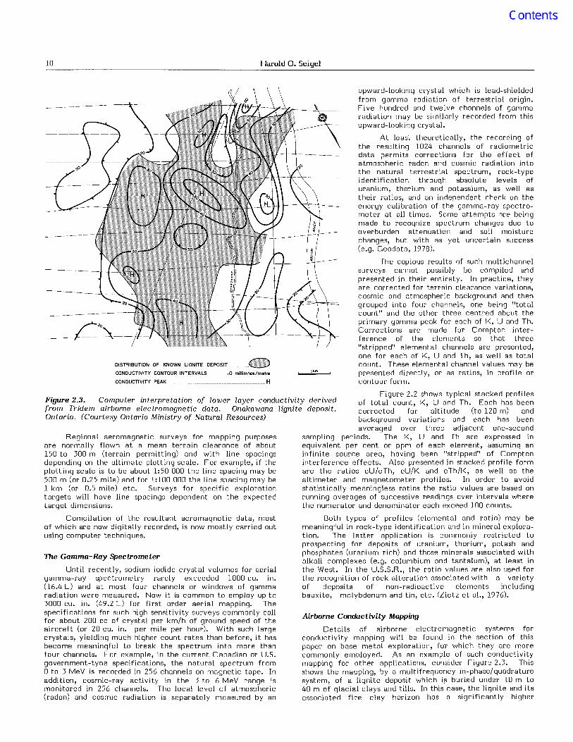
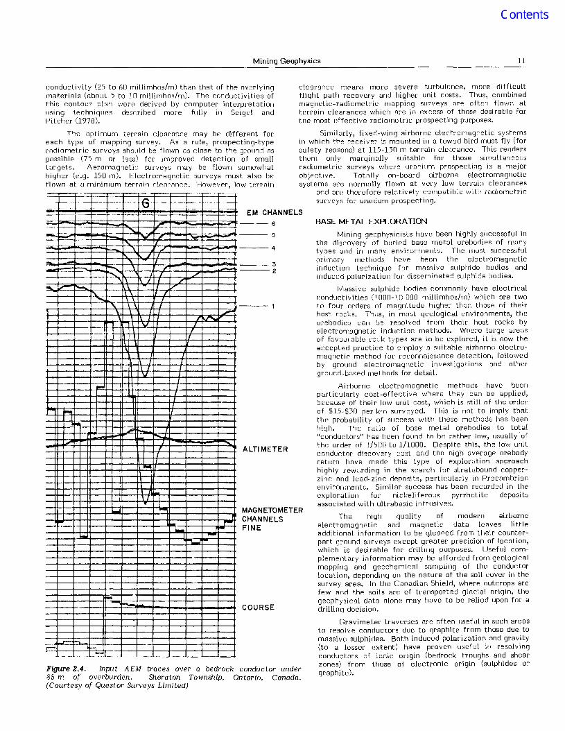
Figure 2.4. Input AEM traces over a bedrock conductor under85 m of overburden. Sheraton Township, Ontario, Canada.(Courtesy of Questor Surveys Limited)
clearance means more severe turbulence, more di fficultflight path recovery and higher unit costs. Thus, combinedmagnetic-radiometric mapping surveys are often flown atterrain clearances which are in excess of those desirable forthe most effective radiometric prospecting purposes.
Similarly, fixed-wing airborne electromagnetic systemsin which the receiver is mounted in a towed bird must fly (forsafety reasons) at 115-130 m terrain clearance. This rendersthem only marginally suitable for those simultaneousradiometric surveys where uranium prospecting is a majorob jective. Totally on-board airborne electromagneticsystems are norm3lly flown at very low terrain clearances
and are therefore relatively compatible with radiometricsurveys for uranium prospecting.
conductivity (25 to 60 millimhos/m) than that of the overlyingmaterials (about 5 to 10 millimhos/m). The conductivities ofthis contour pl;m were derived by computer interpretationusing techniques described more fully in Seigel andPitcher (1978).
The optimum terrain clearance may be different foreach type of mapping survey. As a rule, prospecting-typeradiometric surveys should be flown as close to the ground aspossible (75 m or less) for improved detection of smalltargets. Aeromagnetic surveys may be flown somewhathigher (e.g. 150 m). Electromagnetic surveys must also beflown at u minimum terrain clemance. However, low terrain
Mining geophysicists have been highly successful inthe discovery of buried base metal orebodies of manytypes and in many environments. The most successfulprimary methods have been the electromagneticinduction technique for massive sulphide bodies andinduced polarization for disseminated sulphide bodies.
Massive sulphide bodies commonly have electricalconductivities (J 000-10 000 millimhos/m) which are twoto four orders of magni tude higher than those of theirhost rocks. Thus, in most geological environments, theorebodies can be resolved from their host rocks byelectromagnetic induction methods. Where large areasof favourable rock types are to be explored, it is now theaccepted practice to employ a suitable airbornc electromagnetic method for reconnaissance detection, followedby ground electromagnetic investigations and otherground-based methods for detail.
Airborne electromagnetic methods have beenparticularly cost-effective where they can be applied,because of their low uni t cost, which is still of the orderof $15-$30 per krn surveyed. This is not to imply thatthe probabili ty of success with these methods has beenhigh. The ratio of base metal orebodies to total"conductors" has been found to bc rather low, usually ofthe order of 1/500 to 1/1000. Despite this, the low unitconductor discovery cost and the high average orebodyreturn have made this type of exploration approachhighly rewarding in the search for stratabound copperzinc and lead-zinc deposits, particularly in Prec8mbrianenvironments. Similar success has been recorded in theexploration for nickeli ferous pyrrhotite depositsassociated with ultrabasic intrusives.
The high quality of modern airborneelectromagnetic and magnetic data lcaves Ii ttleaddi tional information to be gleaned from their counterpart ground surveys except greater precision of location,which is desirable for drilling purposes. Useful complementary information may be afforded from geologicalmapping and geochemical sampling of the conductorlocation, depending on the nature of the soil cover in thesurvey area. In the Canadian Shield, where outcrops arefew and the soils are of transported glacial origin, thegeophysical data alone may have to be relied upon for adrilling decision.
Gravimeter traverses are often useful in such areasto resolve conductors due to graphite from those due tomassive sulphides. Both induced polarization and gravity(to a lesser extent) have proven useful in resolvingconductors of ionic origin (bedrock troughs and shearzones) from those of electronic origin (sulphides orgraphite).
BASE METAL EXPLORAnON
COURSE
ALTIMETER
MAGNETOMETERCHANNELSFINE
---3----2
EM CHANNELS
6
5
---4
-------
"'"~-
'" '""-
" J
"- /,---- \ ,. ~
"'""""F 7'
I 1 /
lolL [/
r"I........
" I
"-~
, J'tt..V ,
V- I
-"-'-
T..11'
I- -I- -,...~ --- !""'..-..~
-
~-
~~
.r::= -,--- - -~-
....

12 Harold O. Seigel
The IP method has been particularly useful as a groundfollow-up technique in areas of tropical weathering,particularly in semiarid environments (e.g. Australia).
For a fuller discussion of ground follow-up philosophyand methods, the reader is referred to Seigel (1972).
SALEM, NEW HAM PSI
I
12
The .Airborne Electromagnetic Method
At present, about seven basically different airborneelectromagnetic (AEM) methods are in active use throughoutthe world. Most of these were first developed and utilized inCanada, because of various technical and historical reasons,although increasingly these are now being manufactured
abroad, for example, in Sweden, Finland, U.S.S.R., Indiaand China. A fuller description of AEM systems may befound in Ward (1970).
Recent airborne electromagnetic developmentshave been directed towards expanding the data-gatheringcapabili ties of the systems, leading to the detection andresolution of a broader range of geological conductors, aswell as to improvement in signal to noise ratios. Thelatter objective, when achieved, will automatically resultin an increased depth of exploration as well as higherspatial resolution for near surface targets through areduction of time constants.
1 It is common today for an airborne electromagneticsystem to produce between 6 and 9 simultaneouschannels of data (perhaps not all of it truly independent)for different (transient) times, different frequencies, ordifferent coil configurations. The interpretativepossibili ties of this wealth of data are large. Somecomputer interpretations based on simple geologicalmodels have been developed by the operators of thesesystems and are now being applied on a routine basis.
Perhaps the most widely-used AEM system at thepresent time is the transient system known as Input (e.g.Lazenby, 1973). It measures six slices of theelectromagnetic transient decay at various times out to2.3 S-3 following a 1.1 S-3 primary pulse. In this way, itis able to detect a wide range of geological conductors.
Figure 2.4 shows an Input AEM test profile flownacross a bedrock conductor consisting of a mixedgraphite/sulphide body in Precambrian rocks, under 85 mof relatively poorly conducting overburden. The figureillustrates the exploration depth capability of the InputAEM system under the existing conditions of this test.
Multi-frequency continuous-wave AEM systems,measuring in~phase and quadrature disturbancessimultaneously at several frequencies (e.g. Tridem,operating at 500, 2000 and 8000 Hz; see Seigel andPitcher, 1978), have come into use for the same reasons.
Some AEM systems employ several transmitter andreceiver coil configurations in order to obtaininformation about geological conductors having a varietyof geometries relative to the survey line. For example,the Dighem helicopter system (see Fraser, 1978) employsthree receivers, one coaxial and two orthogonal to thetransmitter coil, with an operating frequency of 918 Hzand a coil separation of 9 m.
Figure 2.5 shows an actual Dighem discoverytraverse over a body of pyrrhotite, pentlandite andchalcopyrite in a Precambrian gabbro intrusive, lyingunder about 20 m of glacially derived soil cover.
The struggle for greater useful depth ofpenetration has been frustrating. Because of theimmutable laws of physics, the signal from a conductingbody drops off, at best, as the inverse third power of theelevation of the airborne electromagnetic system and atworst as the inverse fifth power, depending on therelative parameters of the conductor and the systememployed. Noise due to the aircraft being a conductorcannot be totally eliminated and moreover, thegeological noise associated with undesirable earthconductors cannot be eliminated at all. These factors
1
I
il--
~ ~ -- c..:.'\ +11'1lI-+++-~CII-+ ~
,.... r"
I-
IR
SALEM. NEW HAMPSHIRE. US-A
1-
I
1
I,
I
Figure 2.5. Multichannel single-frequency Dighem helicopterelectromagnetic discovery profile over nickel/copper deposit.Montcalm Township, Ontario, Canada. (Courtesy of GeophysicalEngineering Ltd.)
;AIEM, NE 'M'PSI .' ,\.$,......;~fIln"'~""~.. ~ I [h :: '
:"++--+'-C 1'" 1- .. '.±...L ..J=h"= .[,_
SALEM, NEW HAMPSHIRE, U.S.A
Icc+=r'T I" I .
J'l'M:N£'~c~ ,,,,"'IT-r'CT=T'""''Tlccr.-n'rr·-r [',-,,, ,- "'T-
'Pht'---t"I-I"rc-:Hc
'++'+--1 + + 1·1"+' ++11·+- + I~·FI··+-I·+ ·j·+-+-++~I·'+-I·-
Mining Geophysics 13
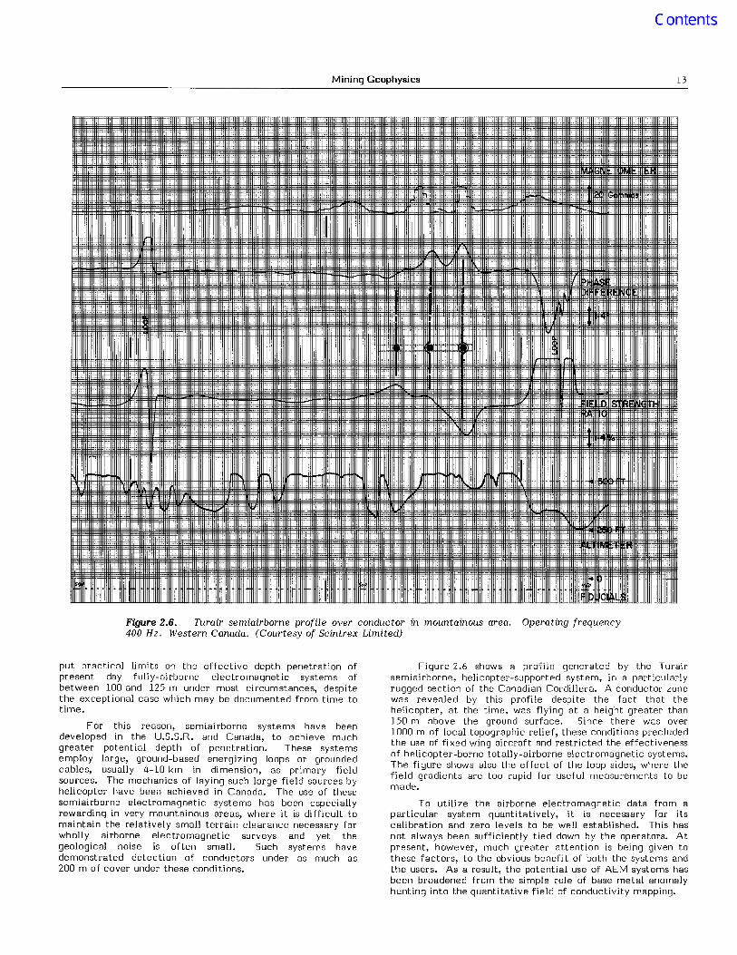
Figure 2.6. Turair semiairborne profile over conductor in mountainous area. Operating frequency400 Hz. Western Canada. (Courtesy of Scintrex Limited)
put practical limits on the effective depth penetration ofpresent day fully-airborne electromagnetic systems ofbetween 100 and 125 m under most circumstances, despitethe exceptional case which may be documented from time totime.
For this reason, semiairborne systems have beendeveloped in the U.S.S.R. and Canada, to achieve muchgreater potential depth of penetration. These systemsemploy large, ground-based energizing loops or groundedcables, usually 4-10 km in dimension, as primary fieldsources. The mechanics of laying such large field sources byhelicopter have been achieved in Canada. The use of thesesemiairborne electromagnetic systems has been especiallyrewarding in very mountainous areas, where it is difficult tomaintain the relatively small terrain clearance necessary forwholly airborne electromagnetic surveys and yet thegeological noise is often small. Such systems havedemonstrated detection of conductors under as much as200 m of cover under these conditions.
Figure 2.6 shows a profile generated by the Turairsemiairborne, helicopter-supported system, in a particularlyrugged section of the Canadian Cordillera. A conductor zonewas revealed by this profile despite the fact that thehelicopter, at the time, was flying at a height greater than150 m above the ground surface. Since there was over1000 m of local topographic relief, these conditions precludedthe use of fixed wing aircraft and restricted the effectivenessof helicopter-borne totally-airborne electromagnetic systems.The figure shows also the effect of the loop sides, where thefield gradients are too rapid for useful measurements to bemade.
To utilize the airborne electromagnetic data from aparticular system quantitatively, it is necessary for itscalibration and zero levels to be well established. This hasnot always been sufficiently tied down by the operators. Atpresent, however, much greater attention is being given tothese factors, to the obvious benefi t of both the systems andthe users. As a result, the potential use of AEM systems hasbeen broadened from the simple role of base metal anomalyhunting into the quantitative field of conductivity mapping.
14 Harold O. Seigel
One interesting aspect of recent airborne electromagnetic experience in Canada clearly illustrates the largeelement of chance (or statistical probability), involved in thistype of exploration approach. The known base metal miningcamps in eastern Canada have been flown and reflown byairborne electromagnetic systems since the first introductionof such surveys in Canada in 1951. Nevertheless, new basemetal mines continue to be found by new surveys in theseareas. Still we cannot say thQt these fresh discoveries occurat greater depths than were possible using the older systems,or were achieved because they did not show up earlierthrough some technical limitation of the older (and thereforepresumably infcrior) systems. Of five relatively recentdiscoverics, two had been missed by earlier surveys becausethey had a very short strike length and probnbly lay betweenthe lines of the earlier survey. One had been previously foundand drilled inadequately so that its nature had not beenproperly investigated. The other two were previously knownto be conductors but had not been followed up because ofinodequat8 geophysical-geological reasoning. Their combinotion of electrical and magnetic properties was such as torelegate them to the rank of uninteresting conductors. Itremained for flew prospectors with better geologicalreosoning (or was it less reliance on conventional geophysicalreasoning?) to take the trouble to investigate thes8conductors and to reveal their ore potential.
As Slichter (1955) and others have pointed out,geophysicol surveying is a statistical procedure and there is arelationship between the line sracing, the probable orebodylenyth and the probability of discovery of the orebody. Onthe basis of such arguments, one may select the line spacingso as to optimize the cost effectiveness or prospecting profitratio of the geophysical program. Ground investigation costs,including line cutting, geophysics and drilling, have escalatedfar more rapidly than those of airborne surveying in the pastdecade. As a result, the cost-effectiveness of an integratedexploration program, which includes airborne and groundphases, will be improved by flying more closely spaced linestoday than was done ten years ago. As an example of thistrend to closer line spacing, our company (Scintrex) hasrecently flown large blocks of mineralogically favourablecountry in Saskatchewan at 120 m (400 ft.) line separationwith an integrated airborne system and has computer rlottedthe results on the scale of 1:5000. These line separations andplotting scales were formerly reserved for ground surveys.
It is interesting that plotting on such large scalesclearly reveals any tiny uncertainty in the flight pathrecovery or in the mosaic preparation. A positioning errorequivalent to only one half second in time produces the mostremarkable "herringboning" in the contours.
The success rotio of airborne electromagnetic surveyingaround the world has been highly variable. In t8mperate andarctic areRS the geophysical condi tions are generallyrelatively good, with little oxidation and only moderatelyconducting soils. The Canadian Shield and particularly theBaltic Shield provide good geophysical and physiographicenvironments for this exploration technique and many majorstratabound base metal bodies, usually of the copper-zinctypes, as well as copper-nickel sulphide bodies, have beenfound using AEM techniques.
The application of these techniques in areflS of tropicalweathering, particularly in arid or semiarid conditions (e.g.Australia and the southwestern Uni ted States), has been farless rewarding to date because of a number of rundamental,adverse factors. Such weathering may easily oxidize amassive sulphide body to 50 m depth, whereas conductors ofgraphi tic, serpentine and saline origin may persist through tothe ground surface. In addition, semiarid and tropical soilsare often highly conducting. In other words, the geologicalnoise level is usually increased and the orebody signal level
decreased in electromagnetic prospecting under conditions oftropical weathering and arid and semiarid desert terrain.This is not to say that airborne electromagnetic methods areof no value in such areas. In fact, there are successful casehistories which prove the contrary. It just means that theodds for discovery are less under these condi tions and one hasto be more cautious in the use of AEM in areas of tropicalweathering and arirl and semiarid terrain.
The Induced Polarization Method
In ground exploration for base metal deposi ts, theinduced polarization method is the primary electricalexploration tool for porphyry coprers, for contactmetamorphic copper deposi ts and even for stratabound copperor lead-zinc deposits. It is often used as the preferredexploration tool in the search for massive copper-zinc ornickeliferous sulphide deposits, in areas with highlyconducting surficial deposits, such as Australia, South Africaand in many wet tropical countries. As was mentionedearlier, the method is being used, with good reason, as aground follow-up tool for airborne electromagnetic surv8ys insuch areas. A volume by Sumner (1976) summarized much ofthe development that has occurred in IP in recent years.
The IP method, as presently practiced, exists in anumber of possible methods of measurement and quantitiesmeasured. These fall into two main categories, viz. thefrequency-domain (continuous wave) and time-domain (ortransient) systems.
Most commonly, the electric fields associated withpolarization current flows in the ground are measuredbetween two potential electrodes (EIP). More recently(Seigel, 1974) there has developed an approach (MIP orMagnetic Induced Polarization) wherein the magnetic fieldsossociated with polarization current flow are measured by asensitivity magnetometer. The nature of EIP and MIPresponses are very different in theory and practice and twomethods appear to be complementary (i.e. advantageous fordifferent problems) rather than competitive.
Within t.he frequency-domain systems, there are anumber of possible methods of measurements and quantitiesmeasured. Truditionally, the percentage change of apparentresistivity with frequency (PFE) has been measured as the IPcharacteristic. More recently, the phase shift between themeasured voltage and the primary current waveforms hasbeen used to yield equivalent information (e.g. Hallof, 1974).Some workers now m8asure complex resistivities and theirchange with frequency to obtain IP information (e.g. Zongeand Wynn, 1975).
Both time-domain and frequency-domain IP systems arein use and the formerly heated conflict between proponentsof the two different approaches has now died away. It isgenerally appreciated that, in IP as in EM, the time-domainor transient method has the advantages of higher potentialsensitivity. Since transient measurements are made after theinducing current pulse has been cut off, they are "absolute"measurements. Thus, one may improve the signal-to-noise ofsuch measurements by increasing the transmitter power,thereby Rlso increasing the sensitivity of the measurementfor low lP responses. In adrlition, many channels of datawhich are obtained simultaneously may give useful information relating to a range of polarizable materials. The lowinherent frequencies commonly employed in time-domainsurveys generally result in lower electromagnetic inductionproblems (at least at later decay times) although the earlierdecay times may be markedly distorted by EM couplingeffects.
The frequency-domain approach has the advantage ofbetter signal-to-noise, or lower primary power, if you prefer.This can be very significant in areas of high magnetotelluric
Mining Geophysics 15
RELATIVE PHASE SHIFT (DEGREE)
rJ)
r~0Cl::
100m
e~t--
POLE DIPOLE ARRAY, o=50rn, n=2CURRENT ELECTRODE TO EAST
I
FREQUENCY EFFECT (PFE)
---e---
FUNDAMENTAL FREQUENCY3Hz
x-·_·- x I Hz
0---0 0.3 Hz
~_ .. _~ O'IHz
~
J~
WlL0-
j
PERCENT
/000en 8000:::W 600I-w::;; 400
I::;;I0 200
>-I-:> 100
~ 80rJ)
60rJ)w0::: 40
I-ZW
200:::
rt0-ct 10
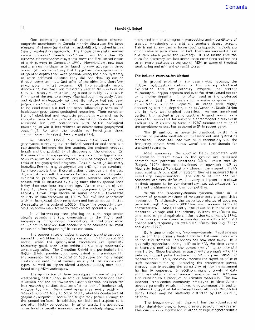
Figure 2.7. Scintl'ex IPRF-2 complex resistivity pole-dipole traverses at fundamental frequencies0.1, 0.3, 1 and 3 Hz. State of Goias, Brazil. (Courtesy of DepartamenLo Nacional Da ProducaoMineral, Brazil)
or industrial noise activity. Being a "relative" method, itssensitivity is usually restricted by the stability of thetransmitted wave form, regardless of the power transmitted.
Over the past few years the trend in IP measurementshas been towards the gathering of more information on rl
routine basis. In the time-domain a number of channels,usually 3 to 6, of transient data, are measuredsimultaneously, in order to obtain the shape as well CIS theampli tude of the transient curve. In the frequency domain,complex resistivities may be measured at a number offrequencies in the range of 0.01 to 100 Hz.
Figure 2.7 shows the results of multi-frequency,frequency-domain EIP complex resistivity mensur8lnents in atropical environment. Pole-dipole traverses were run overthe same line with a comparator type of receiver whichautomatically compares the resistivity amplitudes (PFE) andphase shifts (RPS) at the fundamental and third harmonicresulting from a single transmitted square-wave currentform. Base frequencies of 0.1, 0.3, 1 and 3 Hz wereemployed. It is noteworthy that the high polarization/lowresistivity zone in the central part of the profile shows upmore clearly as the operating frequency is decreased. Inaddition, the RP5, which hns n measure of inherent EMsuppression, has a better geological signal/noise than the PFEat the higher frequencies employed.
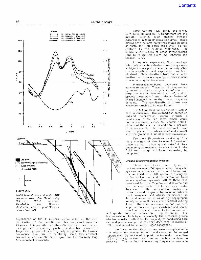
Figure 2.8 presents three of six transient tracesmeasured by a six-channel time-domain receiver in WesternAustralia. A typical interrupted square-wave current pulse oftwo-seconds on-and-off time was employed. Each channelrepresents a time integral of the transient (IP) signal over
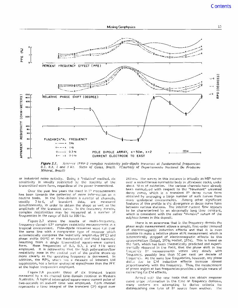
260 ms. The survey in this instance is actually an MIP surveyover a nickeliferous pyrrhotite body in ultrabasic rocks, underabout 30 m of oxidation. The various channels have alreadybeen normalized with respect to the "Newmont" universaldecny curve, which is a transient IP decay curve formobtained by averaging a large number of such cu~ve~ .frommany geological environments. Among other slglllficantfeatures of this profile is the divergence in decay curve formbet ween various stations. The interior current flow appearsto be characterized by an abnormally long time constant,which is consistent with the rather "massive" nature of thesulphide lenses in this deposit.
There is an awareness that in the frequency domain thephase angle measurement allows a simple, first-ord~r removalof electromagnetic induction effects and that it IS. evenpossible to make a relative phase shift measurement which ~s
automatically stripped of electromagnetic ef.fe~ts to thiSapproximation (Seigel, 1974; Hallof, 1974). ThiS IS based onthe fact which has been theoretically predicted and experlmentall; observed in the field, that the phase shift in l?wfrequency IP measurements varies very slowly Withfrequency, possibly less than 50 per cent per decade offrequency. At the same low frequencies, ho.wever, any phaseshifts due to EM inductive effects mcrease almostproportionately with the frequency. Thus, the measurementof phase angles at two frequencies provides a simple means ofcorrecting for EM effects.
Armed with the new tools that can obtain responsecurve shape information in the time or frequency domains,many workers are attempting to derive criteria fordistinguishing one type of IP source from another. The
16 Harold O. Seigel
dependence of the IP response curve shape on the sizedistribution of the metallic particles has been known for25 years. This permits the differentiation of sources of smallaverage particle si7e e.g. graphitic shales, from sources oflarger average particle size, e.g. sulphide grains. The formercommonly give rise to relatively short time-constanttransients, whereas the latter give rise to relatively longtime-constant transi ents.
The MIP method has bcen mostly used todate in Australia. This method can detect aninduced polarization source through aconducting overburden layer which wouldnormally seriously reduce thc electric field IPeffects of the source. In addition, iL permitsIP measurements to be made in areas of loosesand or permafrost, where electrical contactwith the ground is difficult or even impossible.
For those IP receivers producing 10 ormore channels of simultaneous information,there is a trend to having their data fed into acassette-type magnetic tape recorder in thefield for storage and later processing, bycomputer.
Some workers (e.g. Zonqe and Wynn,1975) have claimed ability to differentiate onemetallic sulphide from another throughdifferences in their IP response curves. Theseclaims have become somewhat muted in timeas particular field cases arise which do notconform to the original hypothesis. Inaddition, the results of other investigationstend to refute this claim (e.g. Angoran andMadden, 1977).
In my own experience, IP curve-shapeinformation can be valuahle in resolving sourceambiguities in a particular area, but only afterthe appropriate local experience has beenobtained. Generalizations from one area toanother, or from one geological environmentto another may be dangerous.
Microprocessor-based recei vers havesturted to appear. These can be programmedto record complete complex waveforms in alarge numher of channels (e.g. 1000) and toprocess these wavdorms to derive factors ofIP signi ficance in ei ther the ti me or frequencydomains. The cost/benefit of these newrecei vers remains to be estahlished.
Ground Electromagnetic Systems
There me three basic types ofcontinuous-wave (CW) ground electromagneticsystems in active use in the field today, viz.the vertical-loop or tilt system, the sli ngramor horizontal loop and the Turam, or fixedsource gradient systems. All of thesp- havebeen used for over 25 years and still remain inuse because each fulfills its own usefulfunctions. The vertical-loop system isprimarily used for ground follow-up of airborneelectromagnetic indications, particularly inforested areas ;lnd areus of high topographicrelief, because it can operate without cuttinglines. I he horizontal-loop method has beenimproved in recent years with the addition ofmultiple frequencies -- up to five in one unit,
and greater intercoil separation - up to 240 m. Thehorizontal-loop technique is probably the preferred groundelectromagnetic method for the majority of conducting basemetal deposits, except for the very deep ones (in excess of100 m) and except for areas of rugged topography.
The Turam method finds its best areas of application inthe search for deeply buried conductors, or in ruggedtopography. Detection of sulphide bodies under more than150 m of cover by the Turam method has been achieved inpractice. The number of operating frequencies available
-8
6
4S2So
200Ft.
HN - NORMALIZED AMPLITUDEHSI-CHANNEL I TRANSIENTHS3- CHANNEL 3 TRANSIENTHS!5-CHANNEL 5 TRANSIENT
2N
LEGEND0---'-00-0x····_-x/1---6
4N
domain J'vIIPShoot using
receiver.WesternWestern
6N8N
180
40
Surfoce
Figure 2.8.
Multichannel timeresponse over JanScintrex IPR-8Kambalda area,Australia. (Courtesy ofMines Limited)
_Ore zoneCZZl Sedimenls(sulphidic!grophilic)
8 Mofic inlrusive
L=:J Ullrobosic rocks
Mining Geophysics 17
35 Hz
/05 Hz
comparable CW systems. Both horizontal-loop and Turamconfigurations are being used, the latter requiring but a singlehorizontal receiving coil.
More recently, EM systems are being developed whichmay combine the broad conductor response of the transientsystems and the lower power requirements of the CWsystems. These newer systems employ complex waveformswhich are repetitive but include a number of components ofdiffering frequencies, often harmonically related. Theseinclude the square wave, the saw-toothed waveform of UTEM(ref. Lamontagne and West, 1973) and the pseudo-randomwaveform (Edwards, 1976). Coherent detection is employedusing synchronized crystal clocks or radio links for timereference. Microprocessors may be employed for control ofthe receiver. With such systems the measurements may bemade in terms of the earth impedance vs. frequency spectrumor as its step-function or impulse function response. Themultichannel data are usually stored in digital form onmagnetic tape cassettes. These data may be transformed, forgreater ease of interpretation, from the frequency to thetime domain, or vice versa, by computer or even byprogrammable calculator. Thus, in due course, the advent ofthese complex waveform EM systems will remove thedistinction between time-domain and frequency-domainsystems that presently exists.
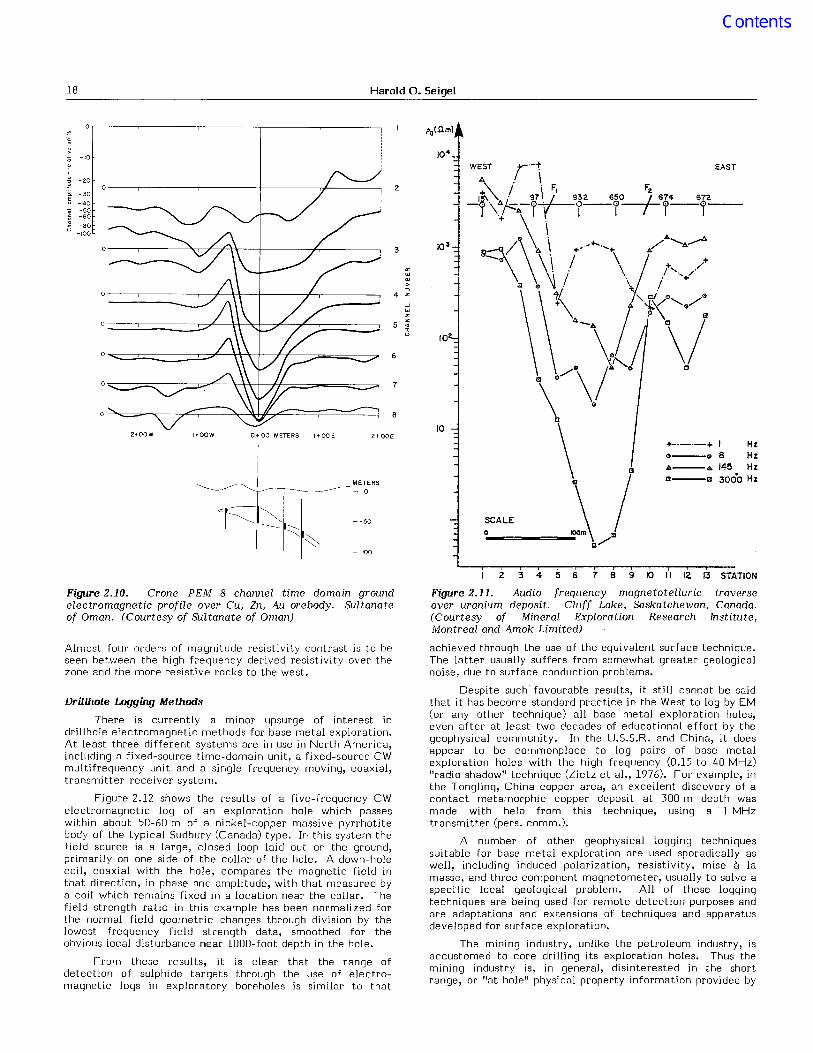
Figure 2.10 presents the measurements made by aneight-channel, time-domain ground electromagnetic system,over a copper-zinc-gold sulphide orebody in a semiaridenvironment. Dual vertical-axis transmitter and receivercoils were employed with centres 50 m apart. A currentpulse with an on/off time of 10.8 ms was employed. Theeight channels of transient electromagnetic decay signalsmeasured range in a logarithmic fashion from 0.15 ms(channel 1) to 8 ms (channel 8) in delay times. The orebody isin Cretaceous andesites and basalts, under 30-40 m ofoxidation and soil cover. It is noteworthy that the orebodyshows up best on the intermediate channels. The shortesttime channel (1) does not distinguish the orebody responsefrom geological noise. The longest time channcl (8) givesonly a low order orebody response.
The long wave VLF radio transmissions, primarily in the15-30 kHz region, are employed as sources for one-manelectromagnetic prospecting units. These units usuallymeasure field amplitudes or inclinations. They are attractivefrom the standpoint of cost, weight and speed ofmeasurement. They suffer from a number of limitations, thechief of which is their lack of conductor discriminationbecause of the high operating frequencies and distant sourcegeometry. Nevertheless, VLF-measuring devices are in use inthose areas where geologic noise, particularly overburden isminimal.
The magnetotelluric method, first proposed by Cagniardfor deep sounding for petroleum exploration, has now beenadapted for shallow sounding in mining geophysics, as well aspermafrost problems, etc. In order to respond toshallow structures, in the first few hundred metres of theground surface, frequencies in the audio or near audiorange (1-10 000 Hz) are used. The resultant method issometimes termed Audio Frequency Magnetotellurics or AMT(see Strangway et aI., 1973).
Figure 2.11 is an AMT profile which presents theresistivities calculated from crossed E and H measurements at four irregularly-spaced frequencies in the range of1-3000 11z. The profile is over the Cluff Lake, Saskatchewanuranium orebody which is associated with a fracture zone inPrecambrian rocks. Apparently this zone is highly conductingand extends almost to the present ground surface, for theresistiv j l Y decreases progressi vely as the frequency increases.
500 E400E
.::::c.
o=25m
/OOffDUCTOR, AXIS
I
• """'""f'"=.
Loop size 250 m 1I 250 m
._-_. -- _. --_. - --.---'---' ---'-"'-:...
" ._.. i.~ 1'0, ;;'---"':'. " ' ."------'t'\xl · ./._.
./' \.- /j'~,--'.---, /.---- I / /. i
-_·-t-· ..." Z,"'-\ 1 11'1 ? rI08/>---,7''------,------,---.-._.->,........ \ I ........... - ....\ I
100 E \200 E ,,/ \ 300 E I"............... \ f
I .I ,I I
\ I, :\ II II ,I II ,I II II II IU
3/5 Hz
2835 Hz
/.'" ,",__ . . . . . • .__ _ '........... 1 12 ''Z ...'.__ .... __....<:""".---..:--_.__... _~. ::L.- € I 0 00 -r I --._...,.
. .- '--l'".,/;,J.~/\ ........
(-\/' , \. ~ \
/ ( : "-"'/;<" \,-_.--_._-_.--- '- -0 -=L....::::.('...../ .... 'K...:::_><
~,",=---"~6-<1__>\' ;\-\ /\I ;'-~ - f· \...... \
• _ 8 I .......... \....... _-_.--_._- ....
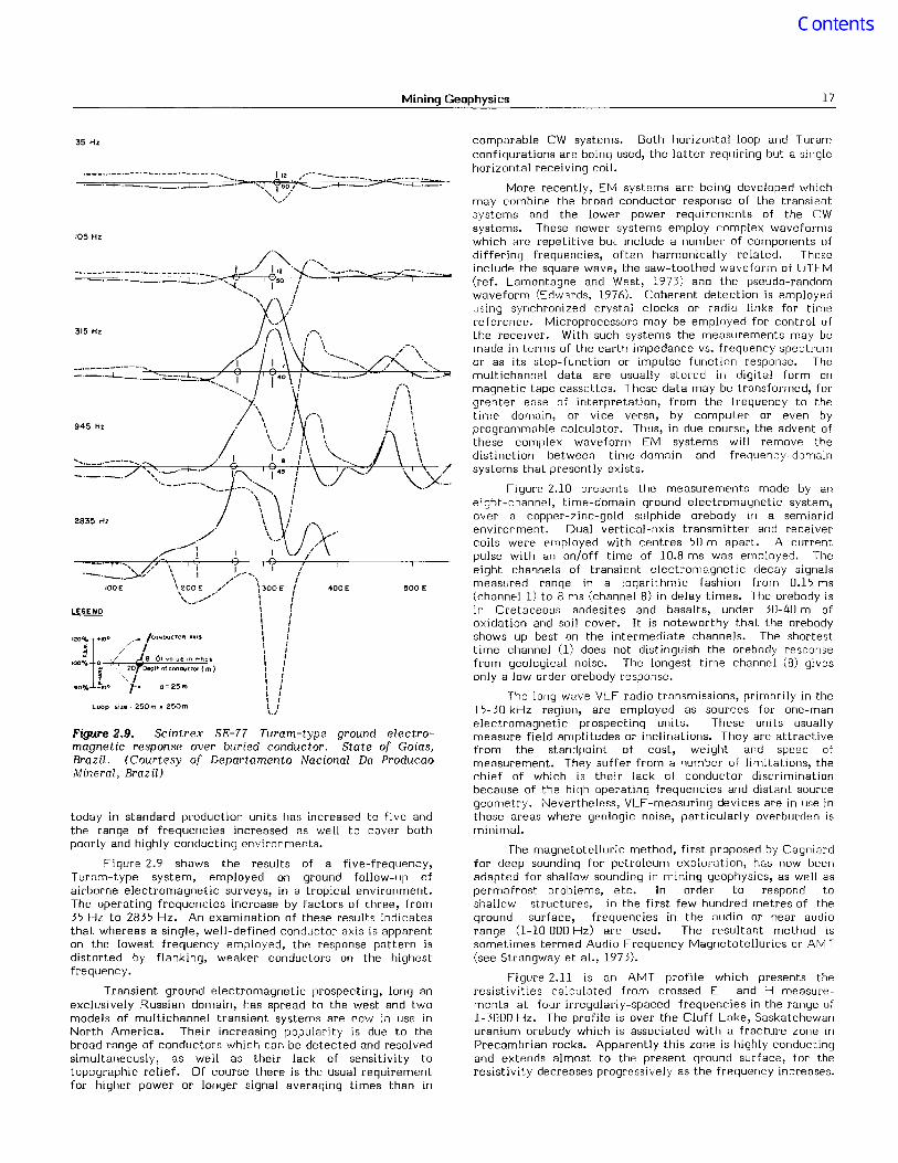
today in standard production units has increased to five andthe range of frequencies increased as well to cover bothpoorly and highly conducting environments.
Figure 2.9 shows the results of a five-frequency,Turam-type system, employed on ground follow-up ofairborne electromagnetic surveys, in a tropical environment.The operating frequencies increase by factors of three, from35 Hz to 2835 Hz. An examination of these results indicatesthat whereas a single, well-defined conductor axis is apparenton the lowest frequency employed, the response pattern isdistorted by flanking, weaker conductors on the highestfrequency.
Transient ground electromagnetic prospecting, long anexclusively Russian domain, has spread to the west and twomodels of multichannel transient systems are now in use inNorth America. Their increasing popularity is due to thebroad range of conductors which can be detected and resolvedsimultaneously, as well as their lack of sensitivity totopographic relief. Of course there is the usual requirementfor higher power or longer signal averaging times than in
Figure 2.9. Scintrex SE-77 Turam-type ground electromagnetic response over buried conductor. State of Goias,Brazil. (Courtesy of Departamento Nacional Da ProducaoMineral, Brazil)
18 Harold O. Seigel
I Hz8 Hz145 Hz3000 Hz
EAST
+_._._+0---0
A---aGl---j3
WEST -r-'-T
A .I i"I 'IF, FzJ ""i...- 97~932 65O--L674 672(\~/~A-I 'y i-I I I-r-
+ \\' \ A ~e.-a/\ \ \ +-~+- ....\ / ~-\ \ \.1 \ / /+..... ./+
\ \\ I \'1' "+",c " ~ . /~{ "<Ji/,,..... /"+\ '" l'\ ',,/ <J
"'-.\/~ \/..'\/ ". .
\ Q
\ .SCALE \ /o...-===o_oc:::=-.....~m\/a
10
3
2
4
10
7
5
8
6
2+00E
METERS
- 0
--100
--50
I+OOW 0+00 METERS I+OOE2 ... 00W
-10
-20
-30
-40-50-60
-80-100
Figure 2.10. Crone PEM 8 channel time domain groundelectromagnetic profile over Cu, Zn, Au orebody. Sultanateof Oman. (Courtesy of Sultanate of Oman)
Almost four orders of magnitude resistivity contrast is to beseen between the high frequency derived resistivity over thezone and the more resistive rocks to the west.
Drillhole Logging Methods
There is currently a minor upsurge of interest indrill hole electromagnetic methods for base metal exploration.At least three different systems are in use in North America,including a fixed-source time-domain unit, a fixed-source CWmultifrequency unit and a single frequency moving, coaxial,transmitter-receiver system.
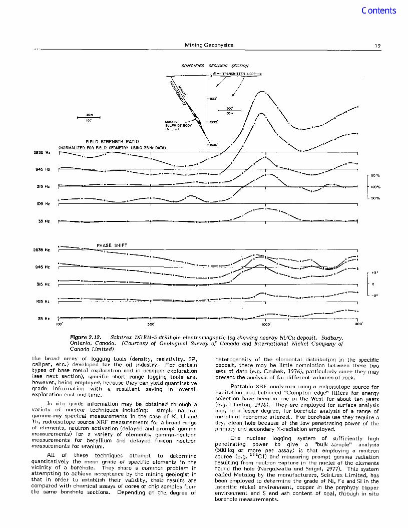
Figure 2.12 shows the results of a five-frequency CWelectromagnetic log of an exploration hole which passeswithin about 50-60 m of a nickel-copper massive pyrrhotitebody of the typical Sudbury (Canada) type. In this system thefield source is a large, closed loop laid out on the ground,primarily on one side of the collar of the hole. A down-holecoil, coaxial with the hole, compares the magnetic field inthat direction, in phase and amplitude, with that measured bya coil which remains fixed in a location near the collar. Thefield strength ratio in this example has been normalized forthe normal field geometric changes through division by thelowest frequency field strength data, smoothed for theobvious local disturbance near 1000-foot depth in the hole.
From these results, it is clear that the range ofdetection of sulphide targets through the use of electromagnetic logs in exploratory boreholes is similar to that
2 3 4 is 6 7 8 9 10 II 12 13 STATION
Figure 2.11. Audio frequency magnetotelluric traverseover uranium deposit. Cluff Lake, Saskatchewan, Canada.(Courtesy of Mineral Exploration Research Institute,Montreal and Amok Limited)
achieved through the use of the equivalent surface technique.The latter usually suffers from somewhat greater geologicalnoise, due to surface conduction problems.
Despite such favourable results, it still cannot be saidthat it has become standard practice in the West to log by EM(or any other technique) all base metal exploration holes,even after at least two decades of educational effort by thegeophysical community. In the U.S.S.R. and China, it doesappear to be commonplace to log pairs of base metalexploration holes with the high frequency (0.15 to 40 MHz)"radio shadow" technique (Zietz et al., 1976). For example, inthe Tongling, China copper area, an excellent discovery of acontact metamorphic copper deposit at 300 m depth wasmade with help from this technique, using a 1 MHztransmitter (pers. comm.).
A number of other geophysical logging techniquessuitable for base metal exploration are used sporadically aswell, including induced polarization, resistivity, mise a lamasse, and three component magnetometer, usually to solve aspecific local geological problem. All of these loggingtechniques are being used for remote detection purposes andare adaptations and extensions of techniques and apparatusdeveloped for surface exploration.
The mining industry, unlike the petroleum industry, isaccustomed to core drilling its exploration holes. Thus themining industry is, in general, disinterested in the shortrange, or "at hole" physical property information provided by
Mining Geophysics 19
SIMPLIFIED GEOLOGIC SECTION
[
110%
100%
90%
..--+........+............+-""+
,/"0--° ° ........... ..............
~O~ ° ........ _0 0
500'
1500'
1000'
6 -----
,---' '--'___...., ,/",.-/", 0/0", ~o-o==----- II ---- / / • ........... • •
100'
FIELD STRENGTH RATIO(NORMALIZED FOR FIELD GEOMETRY USING 35Hz DATA)
f '______=::.-a i 7 7 I ............-:. 7 I------... ,-'___.. __'-.-A /. +--..... """'"'--. *", /" +
-------.-.--. /+ "-
__------,. 0 $- TRANSMITTER LOOP-
~// ,/"," ,/
11'//
i I
*_.---- O_j_O /" I +
+ +............+ ++-+-+-+-- ---+......- .............+-+......-
35 Hz
315 Hz
105 Hz
945 Hz
2835 Hz
2835 Hz'_'____. PHASE SHIFT
945 Hz
315 Hz
105 Hz+ + +-r *---- ......*-+-+
35 Hz
._._0_0"""--°--0-'-'-.'l-'j====+====+"'....---I~""""""=tt==="-yl'-""-_--y"""'='O'R "y-=::.c•..,--...._-'"•.::::::-,,----=,;.==.::..:::....--,---.....,----,~ ~ ~ ~
Figure 2.12. Scintrex DHEM-5 drillhole electromagnetic log showing nearby Ni!Cu deposit. Sudbury,Ontario, Canada. (Courtesy of Geological Survey of Canada and International Nickel Company ofCanada Limited)
the broad array of logging tools (density, resistivity, SP,caliper, etc.) developed for the oil industry. For certaintypes of base metal exploration and in uranium exploration(see next section), specific short range logging tools are,however, being employed, because they can yield quantitativegrade information with a resultant saving in overallexploration cost and time.
In situ grade information may be obtained through avariety of nuclear techniques including: simple naturalgamma-ray spectral measurements in the case of K, U andTh, radioisotope source XRF measurements for a broad rangeof elements, neutron activation (delayed and prompt gammameasurements) for a variety of elements, gamma-neutronmeasurements for beryllium and delayed fission neutronmeasurements for uranium.
All of these techniques attempt to determinequantitatively the mean grade of specific elements in thevicinity of a borehole. They share a common problem inattempting to achieve acceptance by the mining geologist inthat in order to establish their validity, their results arecompared with chemical assays of cores or chip samples fromthe same borehole sections. Depending on the degree of
heterogeneity of the elemental distribution in the specificdeposit, there may be little correlation between these twosets of data (e.g. Czubek, 1976), particularly since they maypresent the analysis of far different volumes of rock.
Portable XRF analyzers using a radioisotope source forexcitation and balanced "Compton edge" filters for energyselection have been in use in the West for about ten years(e.g. Clayton, 1976). They are employed for surface analysisand, to a lesser degree, for borehole analysis of a range ofmetals of economic interest. For borehole use they require adry, clean hole because of the low penetrating power of theprimary and secondary X-radiation employed.
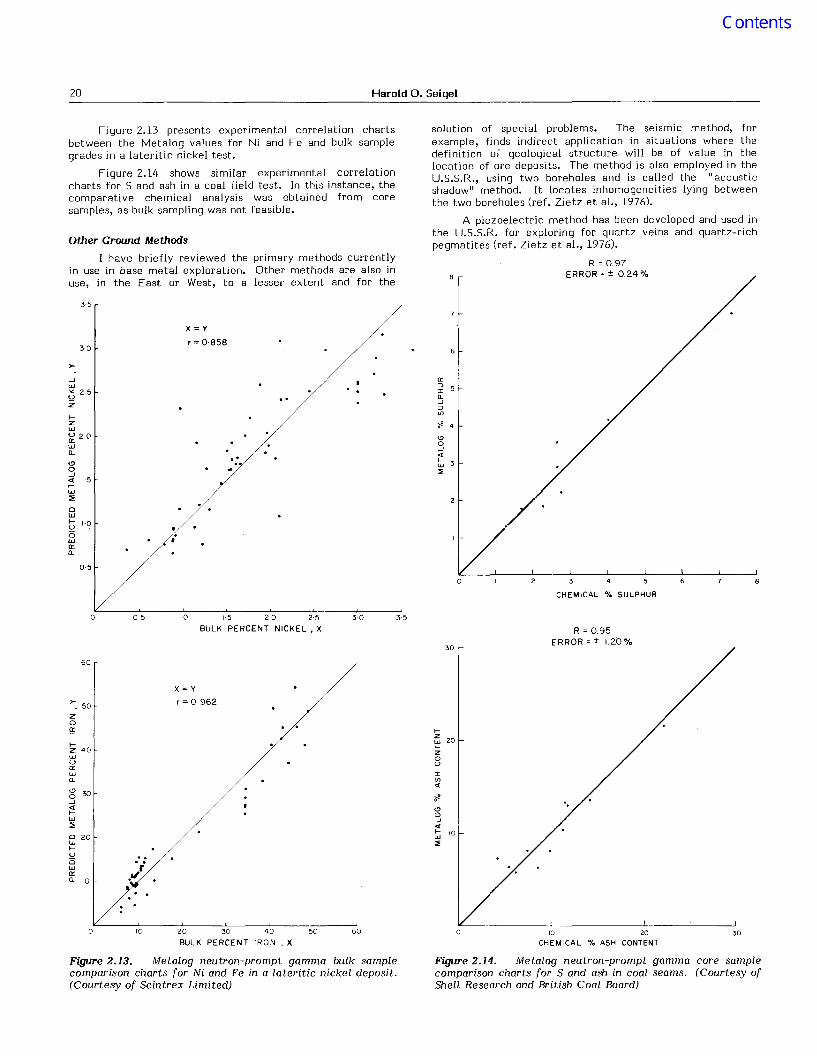
One nuclear logging system of sufficiently highpenetrating power to give a "bulk sample" analysis(500 kg or more per assay) is that employing a neutronsource (e.g. 25 2Cf) and measuring prompt gamma radiationresulting from neutron capture in the nuclei of the elementsround the hole (Nargolwalla and Seigel, 1977). This systemcalled Metalog by the manufacturers, Scintrex Limited, hasbeen employed to determine the grade of Ni, Fe and Si in thelateritic nickel environment, copper in the porphyry copperenvironment and S and ash content of coal, through in situborehole measurements.
20 Harold O. Seigel
35
a::::>Ia.-'::>U)
6
solution of special problems. The seismic method, forexample, finds indirect application in situations where thedefinition of geological structure will be of value in thelocation of ore deposits. The method is also employed in theU.S.S.R., using two boreholes and is called the "acousticshadow" method. It locates inhomogeneities lying betweenthe two boreholes (ref. Zietz et al., 1976).
A piezoelectric method has been developed and used inthe U.S.S.R. for exploring for quartz veins and quartz-richpegmatites (ref. Zietz et al., 1976).
R =097ERROR = ± 0.24 %
..
X=y
r = 0·8583·0
>--oJW
"" 2 5~Z
I-Zw~ 20wa..Cl0-oJ« 15I-w:::.0wI- 1·0uCi ,.wa::a..
0·5
Figure 2.13 presents experimental correlation chartsbetween the Metalog values for Ni and Fe and bulk samplegrades in a lateritic nickel test.
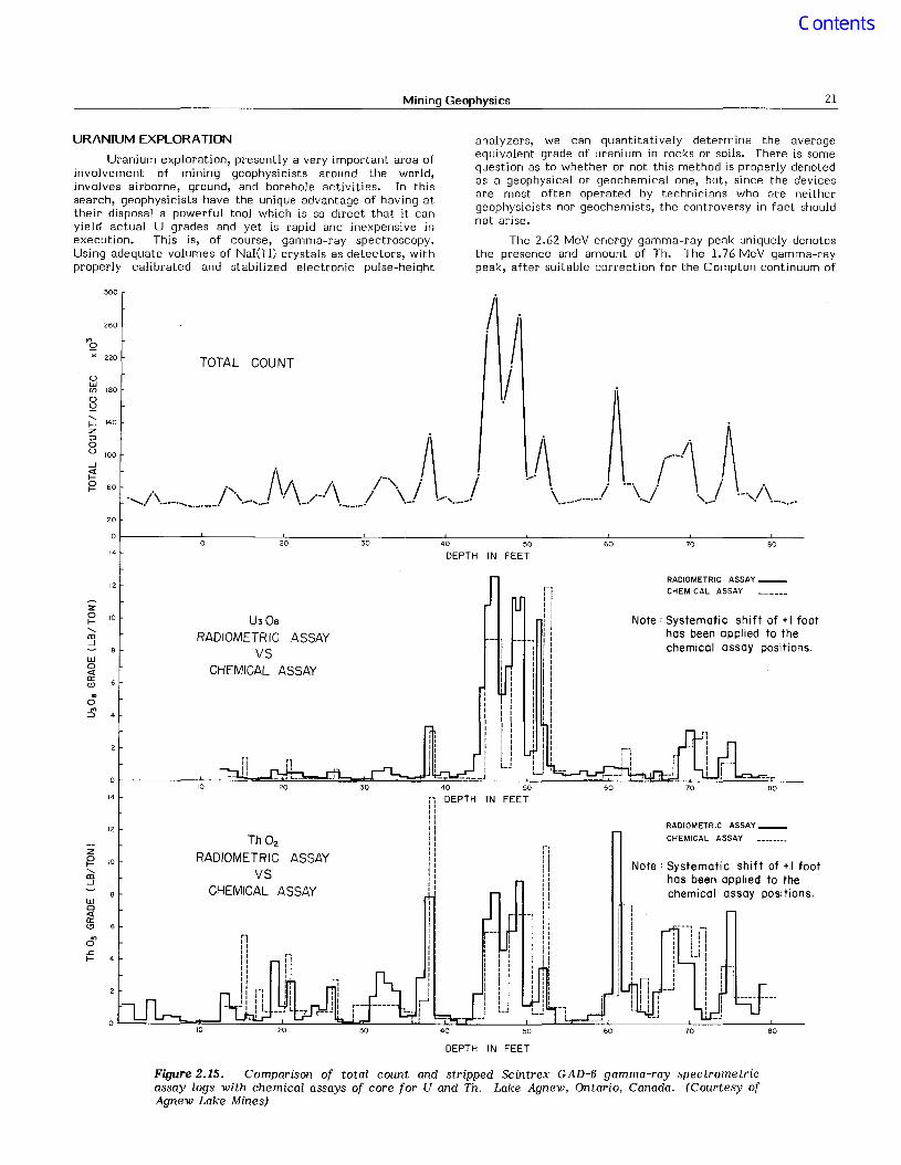
Figure 2.14 shows similar experimental correlationcharts for S and ash in a coal field test. In this instance, thecomparative chemical analysis was obtained from coresamples, as bulk sampling was not feasible.
Other Ground Methods
I have briefly reviewed the primary methods currentlyin use in base metal exploration. Other methods are also inuse, in the East or West, to a lesser extent and for the
o 6
CHEMICAL % SULPHUR
o 05 10 1·5 2·0 2·5
BULK PERCENT NICKEL. X30 35
30
R = 0.95ERROR = ± 1.20%
3010 20CHEMICAL % ASH CONTENT
IZWIZoU
IU)..
Figure 2.14. Metalog neutron-prompt gamma core samplecomparison charts for S and ash in coal seams. (Courtesy ofShell Research and British Coal Board)
60
X=y
r = 0962
10o 20 30 40 50
BULK PERCENT IRON, X
Figure 2.13. Metalog neutron-prompt gamma bulk samplecomparison charts for Ni and Fe in a lateritic nickel deposit.(Courtesy of Scintrex Limited)
>-. 50
zoa::
60
I-Z 40wua::wa..
g 30-oJ
;'!W:::.o 20wI-UCiwa::a.. 10
Mining Geophysics 21
URANIUM EXPLORAnON
Uranium exploration, presently a very important area ofinvolvement of mining geophysicists around the world,involves airborne, ground, and borehole activities. In thissearch, geophysicists have the unique advantage of having attheir disposal a powerful tool which is so direct that it canyield actual U grades and yet is rapid and inexpensive inexecution. This is, of course, gamma-ray spectroscopy.Using adequate volumes of NaI(Tl) crystals as detectors, withproperly calibrated and stabilized electronic pulse-height
analyzers, we can quantitatively determine the averageequivalent grade of uranium in rocks or soils. There is somequestion as to whether or not this method is properly denotedas a geophysical or geochemical one, but, since the devicesare most often operated by technicians who are neithergeophysicists nor geochemists, the controversy in fact shouldnot arise.
The 2.62 MeV energy gamma-ray peak uniquely denotesthe presence and amount of Th. The 1.76 MeV gamma-raypeak, after suitable correction for the Compton continuum of
300
260
"'9)( 220
owen 180
o9
TOTAL COUNT
I .. I
.I
_rJ\ ~
\. / . / '-"..1\..... '.-. . .-.........
U30eRADIOMETRIC ASSAY
VSCHEMICAL ASSAY
RADIOMETRIC ASSAY __
CHEMICAL ASSAY
Note: Systematic shift of + I foothas been applied to thechemical assay positions.
80
807060
,-,I,,,!1,IIIII
IIIIIIII
40 50
DEPTH IN FEET302010
10
20
0
'4
12
Z0 10I-.....m---J
w0«a::<9..0
'":;:)
14
12
Zg 10.....m---J
w0«a::<9
'"0.cI-
ThOzRADIOMETRIC ASSAY
VSCHEMICAL ASSAY
," DEPTH IN FEET1IIIIIIIII1II,I
RADIOMETRIC ASSAY __
CHEMICAL ASSAY
Note: Systematic shift of + I foothas been applied to thechemical assay positions.
DEPTH IN FEET
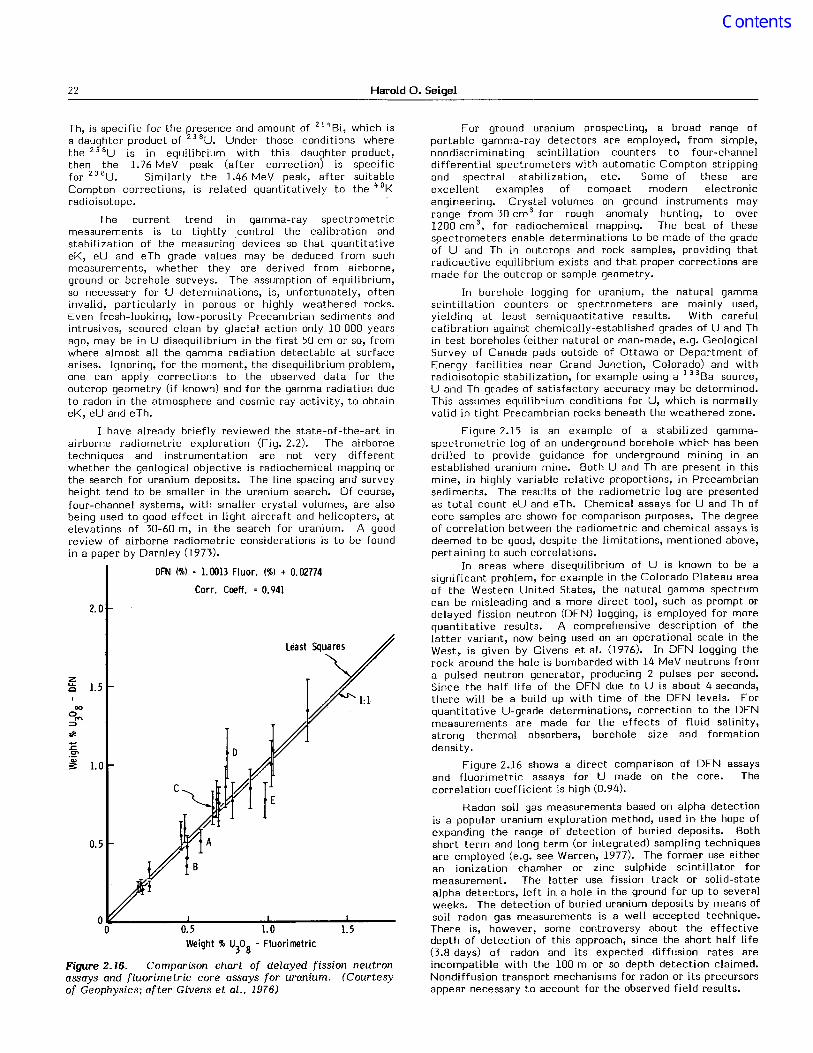
Figure 2.15. Comparison of total count and stripped Scintrex GAD-6 gamma-ray spectrometricassay logs with chemical assays of core for U and Th. Lake Agnew. Ontario. Canada. (Courtesy ofAgnew Lake Mines)
22 Harold O. Seigel
Th, is specific for the presence and amount of 2! "Bi, which isa daughter product of 23SU. Under those conditions wherethe 23 Su is in equilibrium with this daughter product,then the 1.76 MeV peak (after correction) is specificfor 23 BU. Similarly the 1.46 MeV peak, after suitableCompton corrections, is related quantitatively to the ~ oKradioisotope.
The current trend in gamma-ray spectrometricmeasurements is to tightly control the calibration andstabilization of the measuring devices so that quantitativeeK, eU and eTh grade values may be deduced from suchmeasurements, whether they are derived from airborne,ground or borehole surveys. The assumption of equilibrium,so necessary for U determinations, is, unfortunately, ofteninvalid, particularly in porous or highly weathered rocks.Even fresh-looking, low-porosity Precambrian sediments andintrusives, scoured clean by glacial action only 10000 yearsago, may be in U disequilibrium in the first 50 cm or so, fromwhere almost all the gamma radiation detectable at surfacearises. Ignoring, for the moment, the disequilibrium problem,one can apply corrections to the observed data for theoutcrop geometry (if known) and for the gamma radiation dueto radon in the atmosphere and cosmic ray activity, to obtaineK, eU and eTh.
I have already briefly reviewed the state-of-the-art inairborne radiometric exploration (Fig. 2.2). The airbornetechniques and instrumentation are not very differentwhether the geological objective is radiochemical mapping orthe search for uranium deposits. The line spacing and surveyheight tend to be smaller in the uranium search. Of course,four-channel systems, with smaller crystal volumes, are alsobeing used to good effect in light aircraft and helicopters, atelevations of 30-60 m, in the search for uranium. A goodreview of airborne radiometric considerations is to be foundin a paper by Darnley (1973).
DFN (%) : 1. 0013 Fluor. (%) + 0.02774
Corr. Cooff. : 0.941
2.0
z..... 1.5<:>
00
0""::>
>J<
:EC"
~ 1.0
0.5
0.5 I. 0 1.5Weight % U
30g - Fluori metric
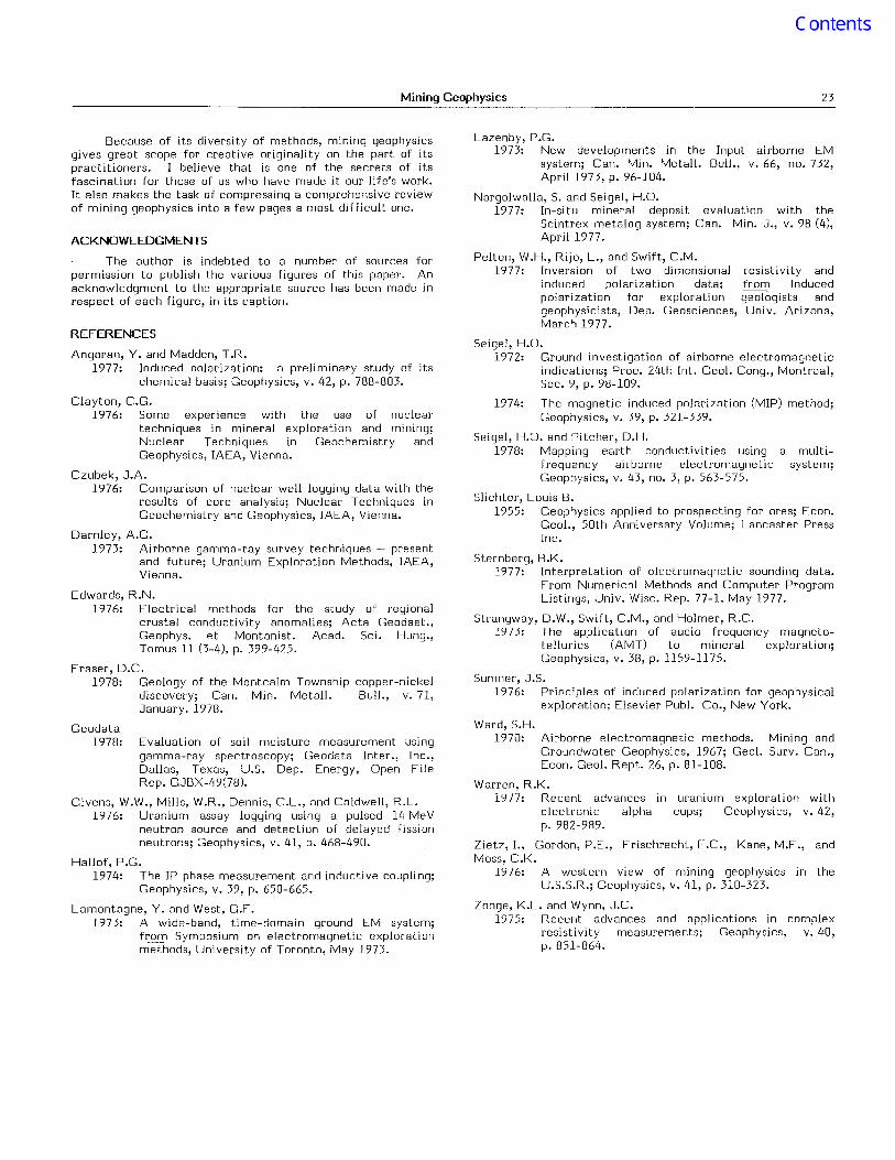
Figure 2.16. Comparison chart of delayed tission neutronassays and fluorimetric core assays for uranium. (Courtesyof Geophysics; after Givens et aI., 1976)
For ground uranium prospecting, a broad range ofportable gamma-ray detectors are employed, from simple,nondiscriminating scintillation counters to four-channeldifferential spectrometers with automatic Compton strippingand spectral stabilization, etc. Some of these areexcellent examples of compact modern electronicengineering. Crystal volumes on ground instruments mayrange from 30 cm 3 for rough anomaly hunting, to over1200 cm3, for radiochemical mapping. The best of thesespectrometers enable determinations to be made of the gradeof U and Th in outcrops and rock samples, providing thatradioactive equilibrium exists and that proper corrections aremade for the outcrop or sample geometry.
In borehole logging for uranium, the natural gammascintillation counters or spectrometers are mainly used,yielding at least semiquantitative results. With carefulcalibration against chemically-established grades of U and Thin test boreholes (either natural or man-made, e.g. GeologicalSurvey of Canada pads outside of Ottawa or Department ofEnergy facilities near Grand Junction, Colorado) and withradioisotopic stabilization, for example using a 13 3Ba source,U and Th grades of satisfactory accuracy may be determined.This assumes equilibrium conditions for U, which is normallyvalid in tight Precambrian rocks beneath the weathered zone.
Figure 2.15 is an example of a stabilized gammaspectrometric log of an underground borehole which has beendrilled to provide guidance for underground mining in anestablished uranium mine. Both U and Th are present in thismine, in highly variable relative proportions, in Precambriansediments. The results of the radiometric log are presentedas total count eU and eTh. Chemical assays for U and Th ofcore samples are shown for comparison purposes. The degreeof correlation between the radiometric and chemical assays isdeemed to be good, despite the limitations, mentioned above,pertaining to such correlations.
In areas where disequilibrium of U is known to be asignificant problem, for example in the Colorado Plateau areaof the Western United States, the natural gamma spectrumcan be misleading and a more direct tool, such as prompt ordelayed fission neutron (DFN) logging, is employed for morequantitative results. A comprehensive description of thelatter variant, now being used on an operational scale in theWest, is given by Givens et al. (1976). In DFN logging therock around the hole is bombarded with 14 MeV neutrons froma pulsed neutron generator, producing 2 pulses per second.Since the half life of the DFN due to U is about 4 seconds,there will be a build up with time of the DFN levels. Forquantitative U-grade determinations, correction to the DFNmeasurements are made for the effects of fluid salinity,strong thermal absorbers, borehole size and formationdensity.
Figure 2.16 shows a direct comparison of DFN assaysand fluorimetric assays for U made on the core. Thecorrelation coefficient is high (0.94).
Radon soil gas measurements based on alpha detectionis a popular uranium exploration method, used in the hope ofexpanding the range of detection of buried deposits. Bothshort term and long term (or integrated) sampling techniquesare employed (e.g. see Warren, 1977). The former use eitheran ionization chamber or zinc sulphide scintillator formeasurement. The latter use fission track or solid-statealpha detectors, left in a hole in the ground for up to severalweeks. The detection of buried uranium deposits by means ofsoil radon gas measurements is a well accepted technique.There is, however, some controversy about the effectivedepth of detection of this approach, since the short half life0.8 days) of radon and its expected diffusion rates areincompatible with the 100 m or so depth detection claimed.Nondiffusion transport mechanisms for radon or its precursorsappear necessary to account for the observed field results.
Mining Geophysics 23
copper-nickelBull., v. 71,
Geodata1978:
Because of its diversity of methods, mining geophysicsgives great scope for creative originality on the part of itspractitioners. I believe that is one of the secrets of itsfascination for those of us who have made it our life's work.It also makes the task of compressing a comprehensive reviewof mining geophysics into a few pages a most difficult one.
ACKNOWLEDGMENTS
The author is indebted to a number of sources forpermission to publish the various figures of this paper. Anacknowledgment to the appropriate source has been made inrespect of each figure, in its caption.
REFERENCES
Angoran, Y. and Madden, T.R.1977: Induced polarization: a preliminary study of its
chemical basis; Geophysics, v. 42, p. 788-803.
Clayton, C.G.1976: Some experience with the use of nuclear
techniques in mineral exploration and mining;Nuclear Techniques in Geochemistry andGeophysics, IAEA, Vienna.
Czubek, J.A.1976: Comparison of nuclear well logging data with the
results of core analysis; Nuclear Techniques inGeochemistry and Geophysics, IAEA, Vienna.
Darnley, A.G.1973: Airborne gamma-ray survey techniques - present
and future; Uranium Exploration Methods, IAEA,Vienna.
Edwards, R.N.1976: Electrical methods for the study of regional
crustal conductivity anomalies; Acta Geodaet.,Geophys. et Montanist. Acad. Sci. Hung.,Tomus 11 (3-4), p. 399-425.
Fraser, D.C.1978: Geology of the Montcalm Township
discovery; Can. Min. Metall.January. 1978.
Evaluation of soil moisture measurement usinggamma-ray spectroscopy; Geodata Inter., Inc.,Dallas, Texas, U.S. Dep. Energy, Open FileRep. GJBX-49(78).
Givens, W.W., Mills, W.R., Dennis, C.L., and Caldwell, R.L.1976: Uranium assay logging using a pulsed 14 MeV
neutron source and detection of delayed fissionneutrons; Geophysics, v. 41, p. 468-490.
Hallof, P.G.1974: The IP phase measurement and inducti ve coupling;
Geophysics, v. 39, p. 650-665.
Lamontagne, Y. and West, G.F.1973: A wide-band, time-domain ground EM system;
from Symposium on electromagnetic explorationmethods, University of Toronto, May 1973.
Lazenby, P.G.1973: New developments in the Input airborne EM
system; Can. Min. Metall. Bull., v. 66, no. 732,April 1973, p. 96-104.
Nargolwalla, S. and Seigel, H.O.1977: In-situ mineral deposit evaluation with the
Scintrex metalog system; Can. Min. J., v. 98 (4),April 1977.
Pelton, W.H., Rijo, L., and Swift, C.M.1977: Inversion of two dimensional resistivity and
induced polarization data; from Inducedpolarization for exploration geologists andgeophysicists, Dep. Geosciences, Uni v. Arizona,March 1977.
Seigel, H.O.1972: Ground investigation of airborne electromagnetic
indications; Proc. 24th Int. Geol. Cong., Montreal,Sec. 9, p. 98-109.
1974: The magnetic induced polarization (MIP) method;Geophysics, v. 39, p. 321-339.
Seigel, H.O. and Pitcher, D.H.1978: Mapping earth conductivities using a multi
frequency airborne electromagnetic system;Geophysics, v. 43, no. 3, p. 563-575.
Slichter, Louis B.1955: Geophysics applied to prospecting for ores; Econ.
Geol., 50th Anniversary Volume; Lancaster PressInc.
Sternberg, B.K.1977: Interpretation of electromagnetic sounding data.
From Numerical Methods and Computer ProgramListings, Univ. Wisc. Rep. 77-1, May 1977.
Strangway, D.W., Swift, C.M., and Holmer, R.C.1973: The application of audio frequency magneto-
tellurics (AMT) to mineral exploration;Geophysics, v. 38, p. 1159-1175.
Sumner, J.S.1976: Principles of induced polarization for geophysical
exploration; Elsevier Publ. Co., New York.
Ward, S.H.1970: Airborne electromagnetic methods. Mining and
Groundwater Geophysics, 1967; Geol. Surv. Can.,Econ. Geol. Rept. 26, p. 81-108.
Warren, R.K.1977: Recent advances in uranium exploration with
electronic alpha cups; Geophysics, v. 42,p. 982-989.
Zietz, I., Gordon, P.E., Frischrecht, F .C., Kane, M.F., andMoss, C.K.
1976: A western view of mining geophysics in theU.S.S.R.; Geophysics, v. 41, p. 310-323.
Zonge, K.L. and Wynn, J.C.1975: Recent advances and applications in complex
resistivity measurements; Geophysics, v. 40,p. 851-864.