Embed Size (px)
Citation preview
AN-X-ABRIO-HMI Remote I/O HMI Interface Module
User Manual
Page ii AN-X-ABRIO-HMI November 2011
Because of the variety of uses for the products described in this publication, those responsible for the application and use of these products must satisfy themselves that all necessary steps have been taken to assure that each application and use meets all performance and safety requirements, including any applicable laws, regulations, codes and standards. In no event will Quest Technical Solutions be responsible or liable for indirect or consequential damage resulting from the use or application of these products.
Any illustrations, charts, sample programs, and layout examples shown in this publication are intended solely for purposes of example. Since there are many variables and requirements associated with any particular installation, Quest Technical Solutions does not assume responsibility or liability (to include intellectual property liability) for actual use based upon the examples shown in this publication.
Throughout this manual we use notes to make you aware of safety considerations.
WARNING!
Identifies information about practices or circumstances that can lead to personal injury or death, property damage, or economic loss.
These warnings help to:
• identify a hazard
• avoid the hazard
• recognize the consequences
IMPORTANT! Identifies information that is especially important for successful application and understanding of the product.
TIP Identifies information that explains the best way to use the AN-X-ABRIO-HMI
Microsoft is a registered trademark of Microsoft Corporation.
Windows, Windows XP, Windows Vista and Windows 7 are trademarks of Microsoft Corporation.
ControlLogix, RSLinx and RSLogix 5000 are trademarks of the Allen-Bradley Company, Inc.

AN-X-ABRIO-HMI MODULE OVERVIEW 1
Hardware Features 2
Package Contents 2
Modes of Operation 2
INSTALLATION 4
Prevent Electrostatic Discharge 4
Power 4
Cabling and Termination 4
Ethernet Cabling 5
Software Installation 6
QUICK START 7
ETHERNET CONFIGURATION 8
Ethernet Configuration 8 Standalone Computer 12
Reconfiguring an AN-X from an Unknown State 17
CONFIGURING REMOTE I/O 18
Configuring a Remote I/O Network 18
Configuration File 18
Baud Rate 18
Racks 19
Block Transfers 19
Block Transfers by Length 20 Sample Configuration 20 Sample Block Transfer by Length Configuration 20
Uploading and Downloading Configurations 21
AN-X-ABRIO-HMI Page iii
ACCESSING DATA 22
Configuration 22 PanelView 22 Other HMIs 22
I/O Data 22
Status File Information 23
USING ANXINIT 25
AnxInit Log 25
Locating Available AN-X Modules 26
Selecting an AN-X 27
Set AN-X IP Configuration 28
Restart an AN-X 29
AN-X Info 29
Read Kernel Parameters 30
Run Config Mode 30
Update AN-X Flash 31
Update Firmware 31 Firmware Update Wizard 31 Update Firmware Command 35
Patch Firmware 35
USING THE WEB INTERFACE 37
Automation Network 38 Configure RIO to Enet/IP 38 View Configuration File 38 View Active Configuration 39 View Diagnostic Counters 40
Log Files 41 System Error Log 41 Ethernet/IP Log 41 System Info Log 41 View All Logs 42
Page iv AN-X-ABRIO-HMI November 2011
Administration Menu 42 Browse File System 42 AN-X IP Configuration 42 Archive Configuration 43 Restart AN-X Module 45
TROUBLESHOOTING 46
LEDs 46 Ethernet LEDs 46 SYS LED 46 NET LED – Network Status 47
UPDATING THE FIRMWARE 48
Reading Version Numbers 48
SPECIFICATIONS 49
SUPPORT 50
WARRANTY 51
AN-X-ABRIO-HMI Module Overview
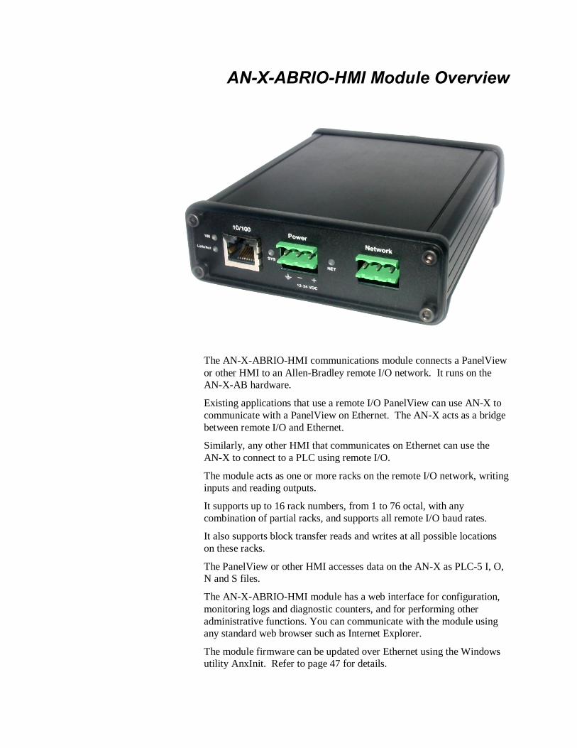
The AN-X-ABRIO-HMI communications module connects a PanelView or other HMI to an Allen-Bradley remote I/O network. It runs on the AN-X-AB hardware.
Existing applications that use a remote I/O PanelView can use AN-X to communicate with a PanelView on Ethernet. The AN-X acts as a bridge between remote I/O and Ethernet.
Similarly, any other HMI that communicates on Ethernet can use the AN-X to connect to a PLC using remote I/O.
The module acts as one or more racks on the remote I/O network, writing inputs and reading outputs.
It supports up to 16 rack numbers, from 1 to 76 octal, with any combination of partial racks, and supports all remote I/O baud rates.
It also supports block transfer reads and writes at all possible locations on these racks.
The PanelView or other HMI accesses data on the AN-X as PLC-5 I, O, N and S files.
The AN-X-ABRIO-HMI module has a web interface for configuration, monitoring logs and diagnostic counters, and for performing other administrative functions. You can communicate with the module using any standard web browser such as Internet Explorer.
The module firmware can be updated over Ethernet using the Windows utility AnxInit. Refer to page 47 for details.
Page 2 AN-X-ABRIO-HMI November 2011
Hardware Features
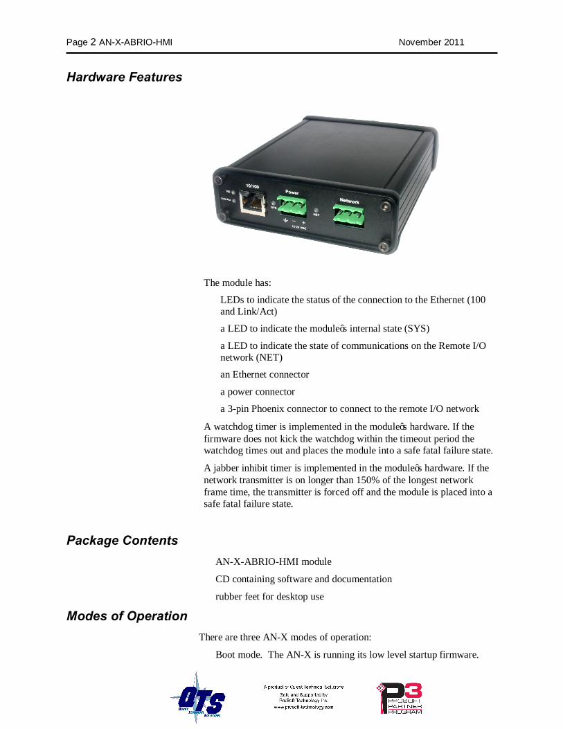
The module has:
• LEDs to indicate the status of the connection to the Ethernet (100 and Link/Act)
• a LED to indicate the module’s internal state (SYS)
• a LED to indicate the state of communications on the Remote I/O network (NET)
• an Ethernet connector
• a power connector
• a 3-pin Phoenix connector to connect to the remote I/O network
A watchdog timer is implemented in the module’s hardware. If the firmware does not kick the watchdog within the timeout period the watchdog times out and places the module into a safe fatal failure state.
A jabber inhibit timer is implemented in the module’s hardware. If the network transmitter is on longer than 150% of the longest network frame time, the transmitter is forced off and the module is placed into a safe fatal failure state.
Package Contents • AN-X-ABRIO-HMI module
• CD containing software and documentation
• rubber feet for desktop use
Modes of Operation There are three AN-X modes of operation:
• Boot mode. The AN-X is running its low level startup firmware.

AN-X-ABRIO-HMI Page 3
• Configuration mode. This is the mode when you are updating the firmware in the AN-X.
• Production mode. This is the normal runtime mode of operation.
Refer to page 29 for information on how to determine the current mode of operation.
Page 4 AN-X-ABRIO-HMI November 2011
Installation Prevent Electrostatic Discharge
The module is sensitive to electrostatic discharge.
WARNING! Electrostatic discharge can damage integrated circuits or semiconductors. Follow these guidelines when you handle the module:
• Touch a grounded object to discharge static potential
• Do not touch the connector pins
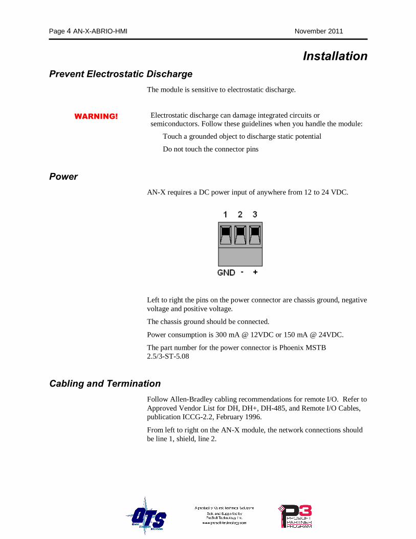
Power AN-X requires a DC power input of anywhere from 12 to 24 VDC.
Left to right the pins on the power connector are chassis ground, negative voltage and positive voltage.
The chassis ground should be connected.
Power consumption is 300 mA @ 12VDC or 150 mA @ 24VDC.
The part number for the power connector is Phoenix MSTB 2.5/3-ST-5.08
Cabling and Termination Follow Allen-Bradley cabling recommendations for remote I/O. Refer to Approved Vendor List for DH, DH+, DH-485, and Remote I/O Cables, publication ICCG-2.2, February 1996.
From left to right on the AN-X module, the network connections should be line 1, shield, line 2.
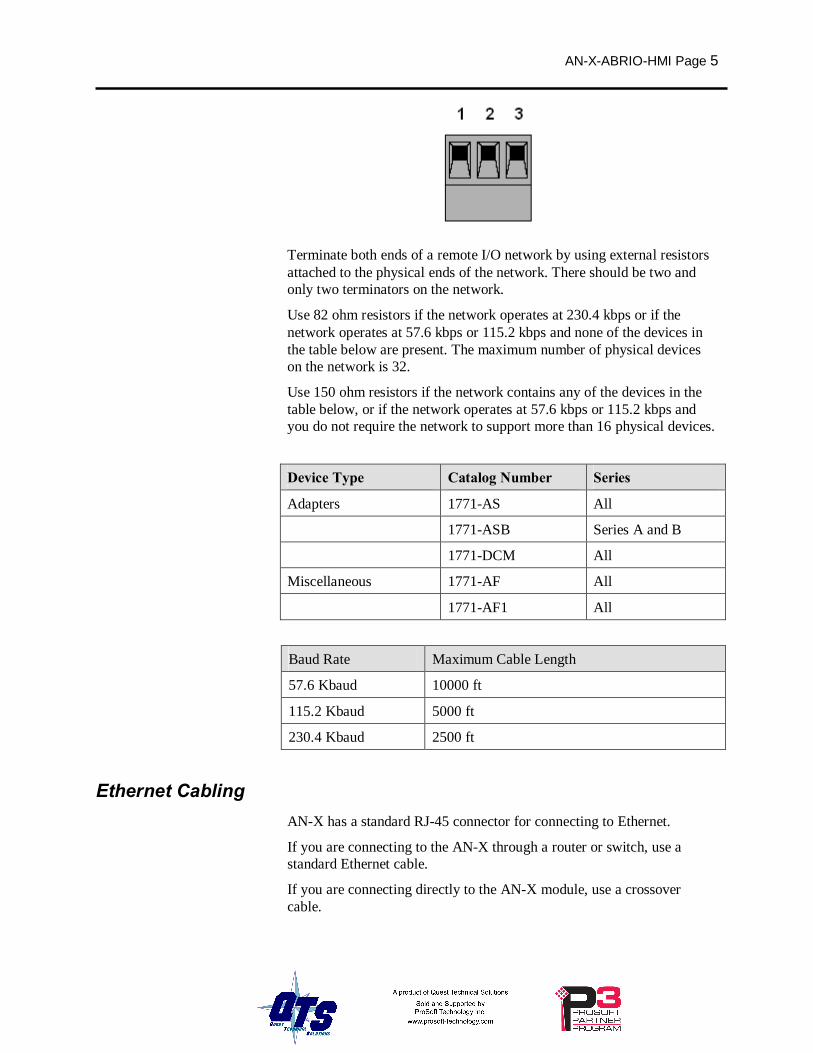
AN-X-ABRIO-HMI Page 5
Terminate both ends of a remote I/O network by using external resistors attached to the physical ends of the network. There should be two and only two terminators on the network.
Use 82 ohm resistors if the network operates at 230.4 kbps or if the network operates at 57.6 kbps or 115.2 kbps and none of the devices in the table below are present. The maximum number of physical devices on the network is 32.
Use 150 ohm resistors if the network contains any of the devices in the table below, or if the network operates at 57.6 kbps or 115.2 kbps and you do not require the network to support more than 16 physical devices.
Device Type Catalog Number Series
Adapters 1771-AS All
1771-ASB Series A and B
1771-DCM All
Miscellaneous 1771-AF All
1771-AF1 All
Baud Rate Maximum Cable Length
57.6 Kbaud 10000 ft
115.2 Kbaud 5000 ft
230.4 Kbaud 2500 ft
Ethernet Cabling AN-X has a standard RJ-45 connector for connecting to Ethernet.
If you are connecting to the AN-X through a router or switch, use a standard Ethernet cable.
If you are connecting directly to the AN-X module, use a crossover cable.

Page 6 AN-X-ABRIO-HMI November 2011
Software Installation You must uninstall any previous version of the software before you can install a new version. Use the Windows Control Panel Add and Remove Programs to remove the old version.
Insert the CD supplied with the AN-X module and run the program setup.exe on the CD to install common AN-X components.
AN-X-ABRIO-HMI Page 7
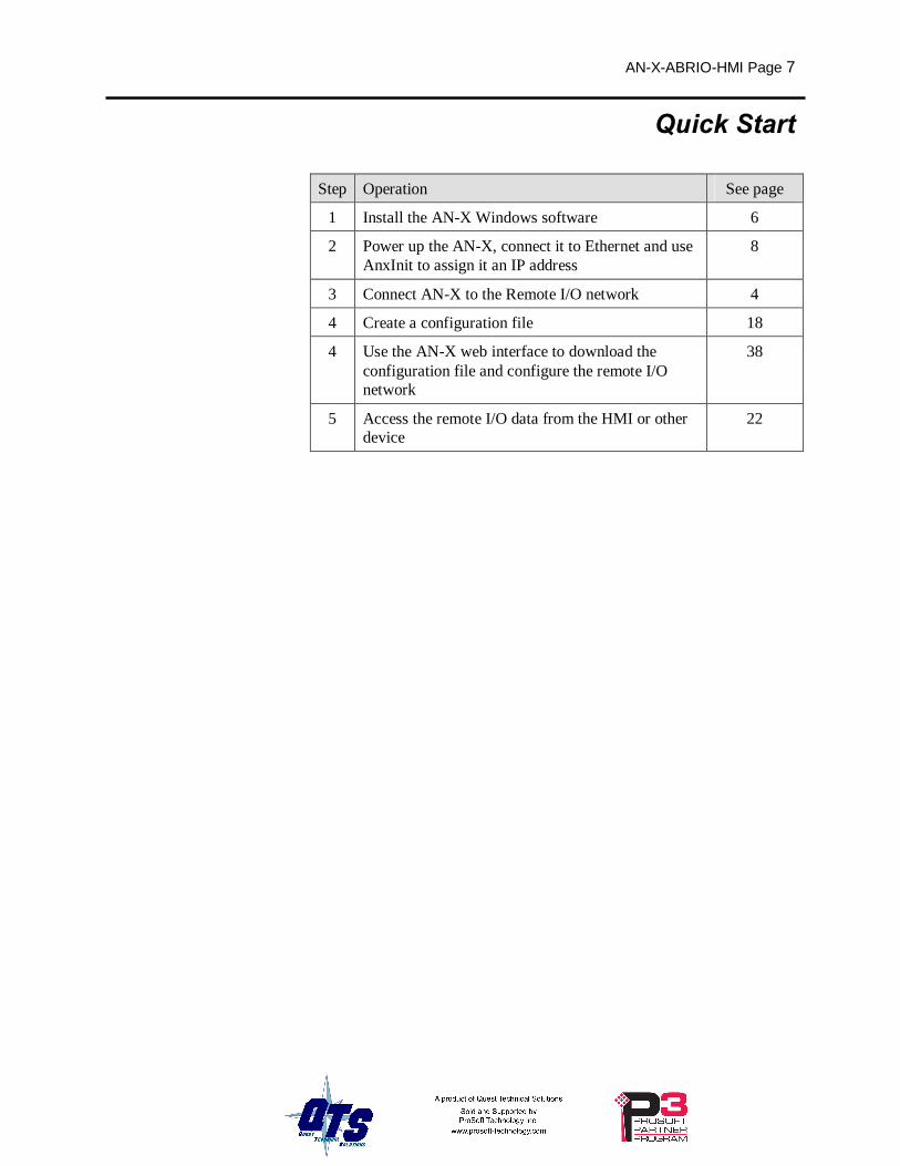
Quick Start
Step Operation See page
1 Install the AN-X Windows software 6
2 Power up the AN-X, connect it to Ethernet and use AnxInit to assign it an IP address
8
3 Connect AN-X to the Remote I/O network 4
4 Create a configuration file 18
4 Use the AN-X web interface to download the configuration file and configure the remote I/O network
38
5 Access the remote I/O data from the HMI or other device
22
Page 8 AN-X-ABRIO-HMI November 2011
Ethernet Configuration Before you can use the AN-X-ABRIO-HMI, you must configure its network properties on Ethernet.
Ethernet Configuration AN-X can be configured to use a static (unchanging) IP address or it can be configured to obtain its IP address from a DHCP server.
Unless you have control of the DHCP server, in most applications you will configure AN-X to use a static IP address. Otherwise the DHCP server may assign a different IP address each time AN-X powers up, and any software that accesses the AN-X module must be reconfigured.
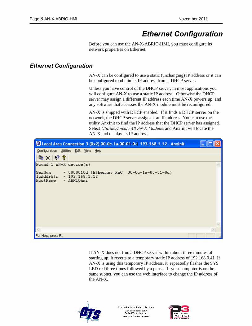
AN-X is shipped with DHCP enabled. If it finds a DHCP server on the network, the DHCP server assigns it an IP address. You can use the utility AnxInit to find the IP address that the DHCP server has assigned. Select Utilities/Locate All AN-X Modules and AnxInit will locate the AN-X and display its IP address.
If AN-X does not find a DHCP server within about three minutes of starting up, it reverts to a temporary static IP address of 192.168.0.41 If AN-X is using this temporary IP address, it repeatedly flashes the SYS LED red three times followed by a pause. If your computer is on the same subnet, you can use the web interface to change the IP address of the AN-X.
AN-X-ABRIO-HMI Page 9
IMPORTANT! Use this temporary IP address only for initial setup of AN-X. AN-X will not function correctly for its intended purpose at the temporary IP address.
If you are using multiple AN-X modules, configure them one at a time, especially if there is no DHCP server on the network, since they will all revert to the same temporary IP address when they fail to find a DHCP server.
IMPORTANT! If you are connecting AN-X to an existing Ethernet network, consult the network administrator to obtain a static IP address for AN-X and to obtain information about how you should configure AN-X.
IMPORTANT! The AN-X must be on the local Ethernet (same subnet as your computer) when you set its IP address.
You configure the Ethernet properties using the Windows utility AnxInit supplied with AN-X or the AN-X web interface.
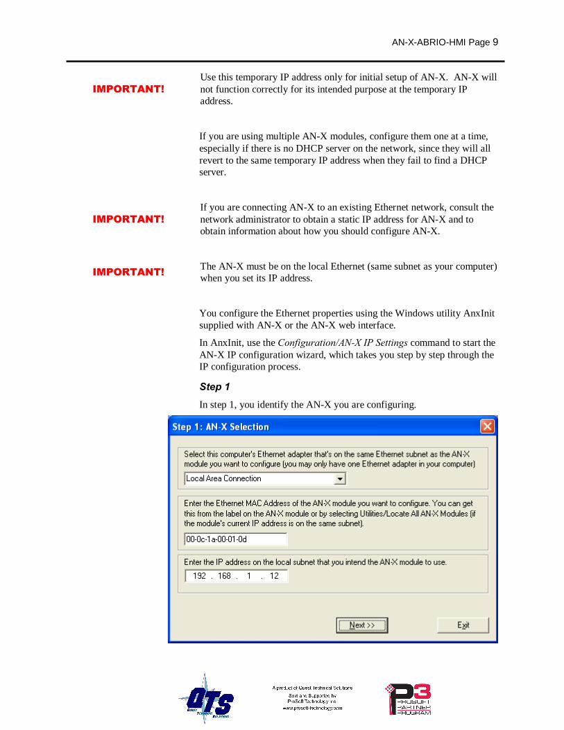
In AnxInit, use the Configuration/AN-X IP Settings command to start the AN-X IP configuration wizard, which takes you step by step through the IP configuration process.
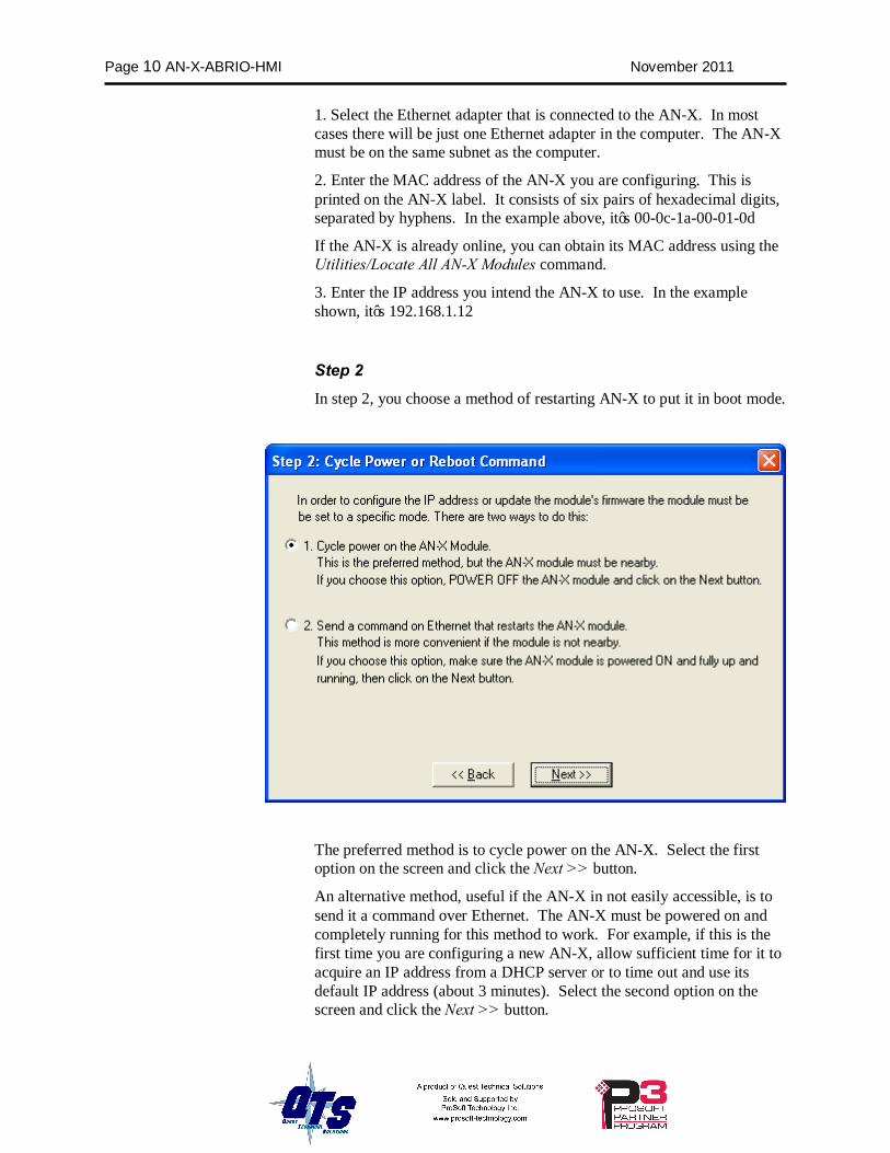
Step 1 In step 1, you identify the AN-X you are configuring.
Page 10 AN-X-ABRIO-HMI November 2011
1. Select the Ethernet adapter that is connected to the AN-X. In most cases there will be just one Ethernet adapter in the computer. The AN-X must be on the same subnet as the computer.
2. Enter the MAC address of the AN-X you are configuring. This is printed on the AN-X label. It consists of six pairs of hexadecimal digits, separated by hyphens. In the example above, it’s 00-0c-1a-00-01-0d
If the AN-X is already online, you can obtain its MAC address using the Utilities/Locate All AN-X Modules command.
3. Enter the IP address you intend the AN-X to use. In the example shown, it’s 192.168.1.12
Step 2 In step 2, you choose a method of restarting AN-X to put it in boot mode.
The preferred method is to cycle power on the AN-X. Select the first option on the screen and click the Next >> button.
An alternative method, useful if the AN-X in not easily accessible, is to send it a command over Ethernet. The AN-X must be powered on and completely running for this method to work. For example, if this is the first time you are configuring a new AN-X, allow sufficient time for it to acquire an IP address from a DHCP server or to time out and use its default IP address (about 3 minutes). Select the second option on the screen and click the Next >> button.
AN-X-ABRIO-HMI Page 11
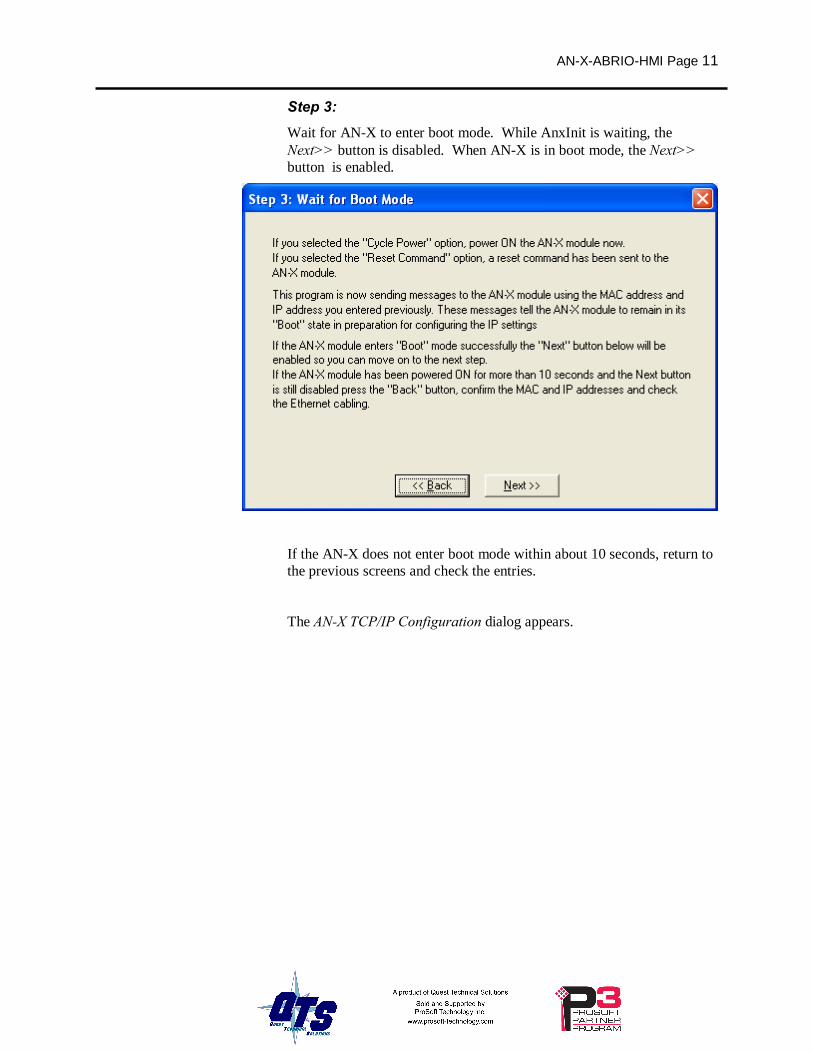
Step 3: Wait for AN-X to enter boot mode. While AnxInit is waiting, the Next>> button is disabled. When AN-X is in boot mode, the Next>> button is enabled.
If the AN-X does not enter boot mode within about 10 seconds, return to the previous screens and check the entries.
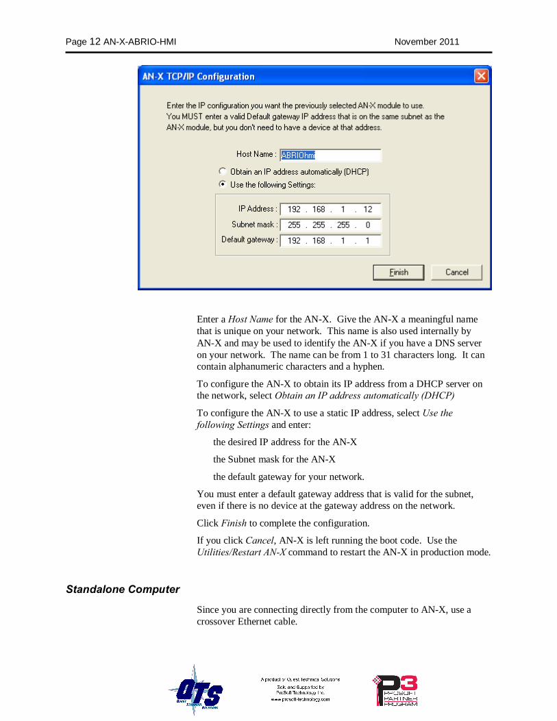
The AN-X TCP/IP Configuration dialog appears.
Page 12 AN-X-ABRIO-HMI November 2011
Enter a Host Name for the AN-X. Give the AN-X a meaningful name that is unique on your network. This name is also used internally by AN-X and may be used to identify the AN-X if you have a DNS server on your network. The name can be from 1 to 31 characters long. It can contain alphanumeric characters and a hyphen.
To configure the AN-X to obtain its IP address from a DHCP server on the network, select Obtain an IP address automatically (DHCP)
To configure the AN-X to use a static IP address, select Use the following Settings and enter:
• the desired IP address for the AN-X
• the Subnet mask for the AN-X
• the default gateway for your network.
You must enter a default gateway address that is valid for the subnet, even if there is no device at the gateway address on the network.
Click Finish to complete the configuration.
If you click Cancel, AN-X is left running the boot code. Use the Utilities/Restart AN-X command to restart the AN-X in production mode.
Standalone Computer
Since you are connecting directly from the computer to AN-X, use a crossover Ethernet cable.
AN-X-ABRIO-HMI Page 13
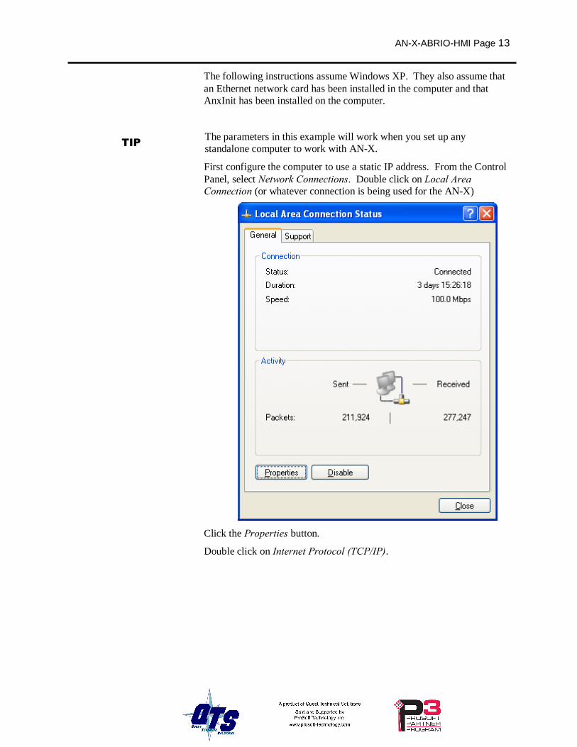
The following instructions assume Windows XP. They also assume that an Ethernet network card has been installed in the computer and that AnxInit has been installed on the computer.
TIP The parameters in this example will work when you set up any standalone computer to work with AN-X.
First configure the computer to use a static IP address. From the Control Panel, select Network Connections. Double click on Local Area Connection (or whatever connection is being used for the AN-X)
Click the Properties button.
Double click on Internet Protocol (TCP/IP).
Page 14 AN-X-ABRIO-HMI November 2011
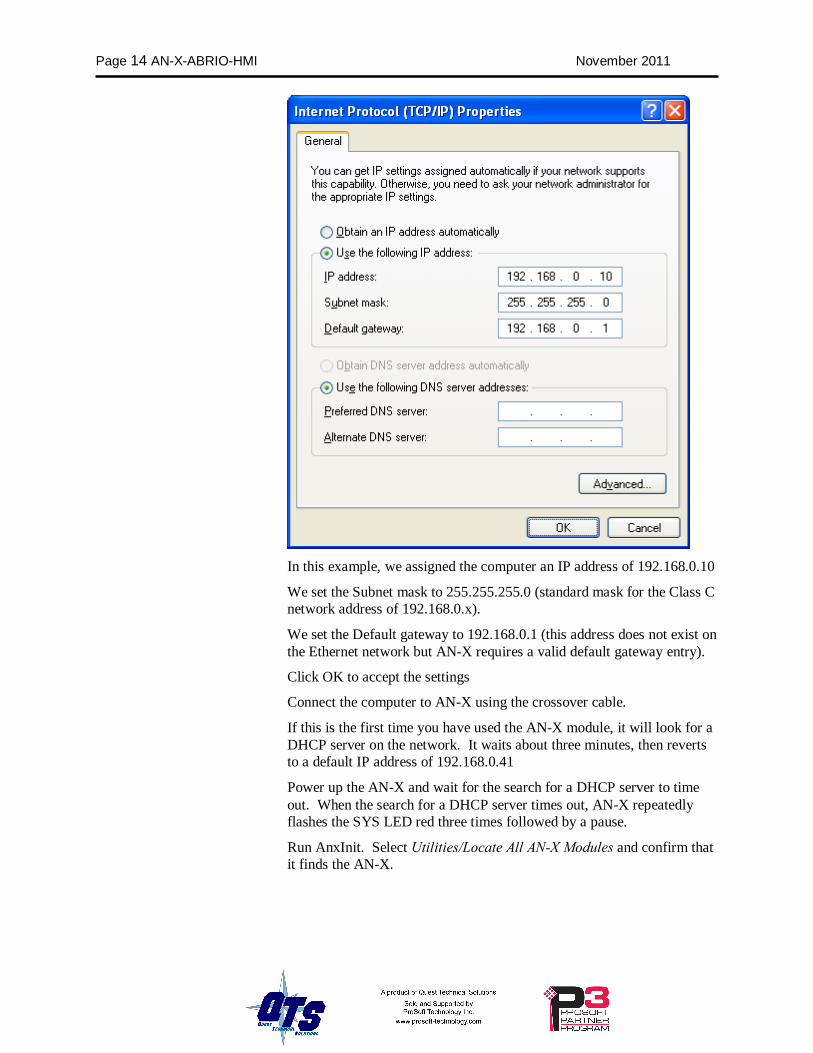
In this example, we assigned the computer an IP address of 192.168.0.10
We set the Subnet mask to 255.255.255.0 (standard mask for the Class C network address of 192.168.0.x).
We set the Default gateway to 192.168.0.1 (this address does not exist on the Ethernet network but AN-X requires a valid default gateway entry).
Click OK to accept the settings
Connect the computer to AN-X using the crossover cable.
If this is the first time you have used the AN-X module, it will look for a DHCP server on the network. It waits about three minutes, then reverts to a default IP address of 192.168.0.41
Power up the AN-X and wait for the search for a DHCP server to time out. When the search for a DHCP server times out, AN-X repeatedly flashes the SYS LED red three times followed by a pause.
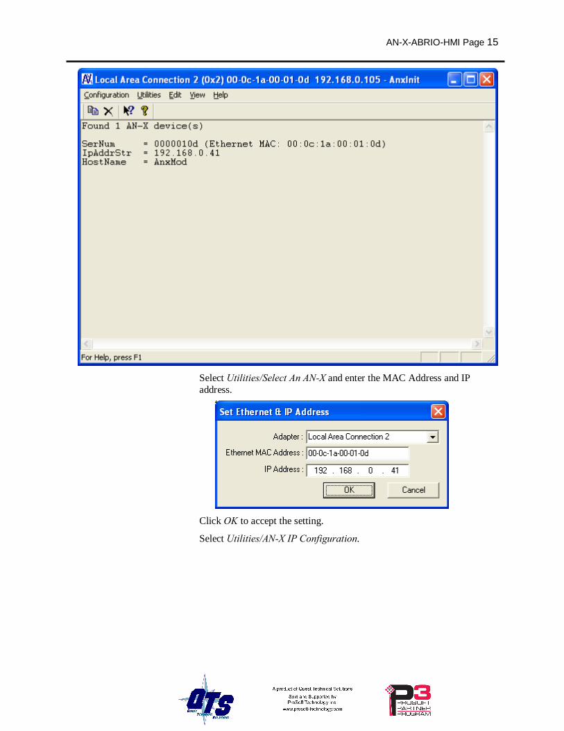
Run AnxInit. Select Utilities/Locate All AN-X Modules and confirm that it finds the AN-X.
AN-X-ABRIO-HMI Page 15
Select Utilities/Select An AN-X and enter the MAC Address and IP address.
Click OK to accept the setting.
Select Utilities/AN-X IP Configuration.
Page 16 AN-X-ABRIO-HMI November 2011
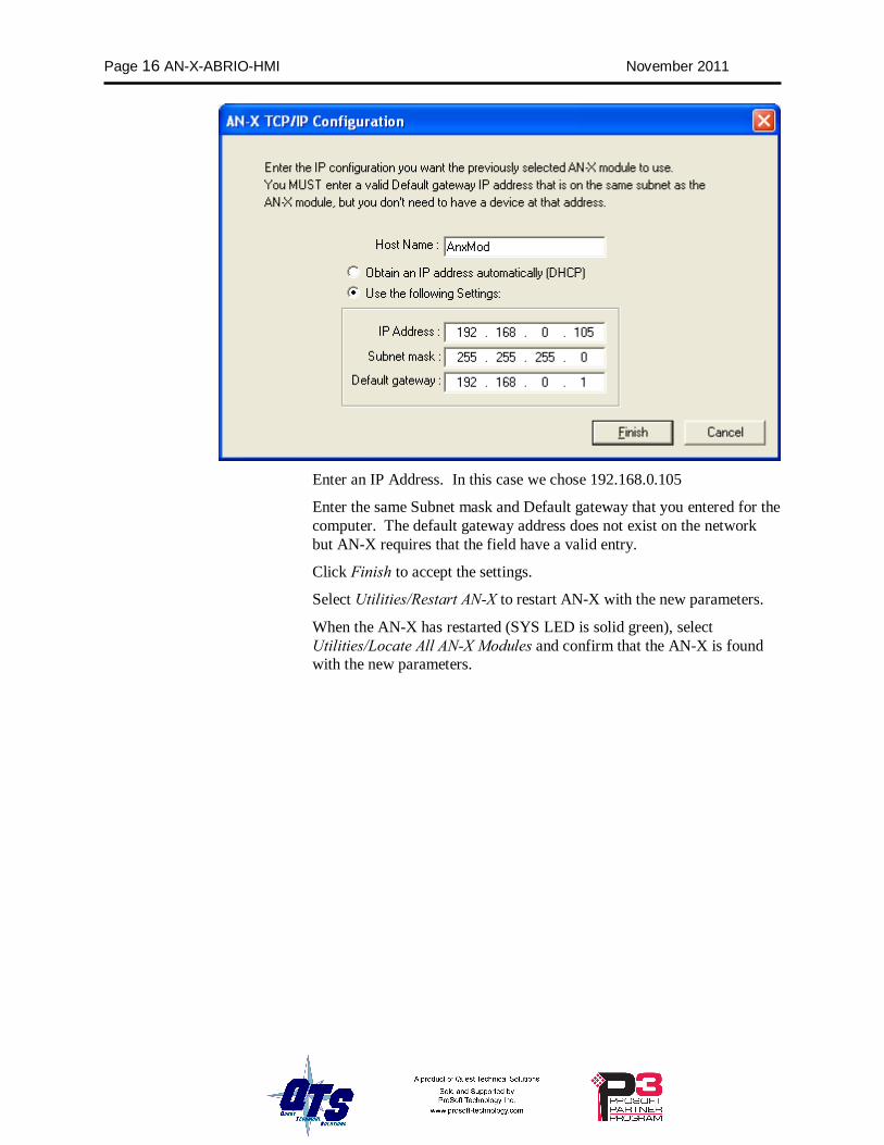
Enter an IP Address. In this case we chose 192.168.0.105
Enter the same Subnet mask and Default gateway that you entered for the computer. The default gateway address does not exist on the network but AN-X requires that the field have a valid entry.
Click Finish to accept the settings.
Select Utilities/Restart AN-X to restart AN-X with the new parameters.
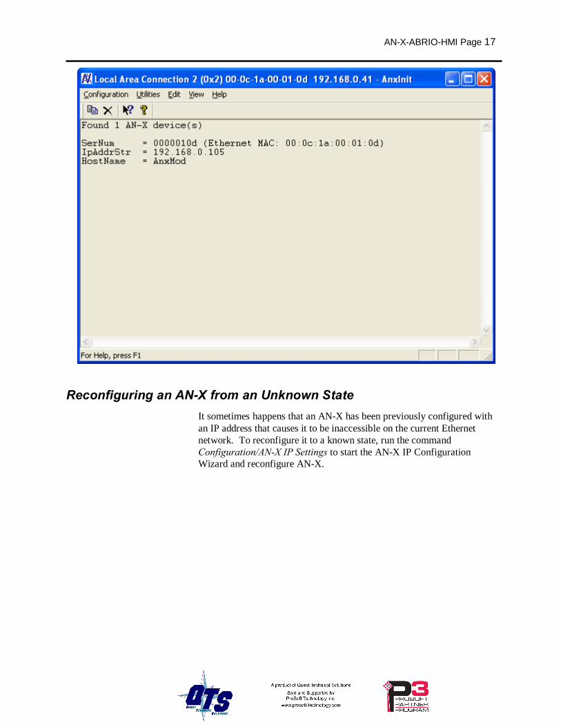
When the AN-X has restarted (SYS LED is solid green), select Utilities/Locate All AN-X Modules and confirm that the AN-X is found with the new parameters.
AN-X-ABRIO-HMI Page 17
Reconfiguring an AN-X from an Unknown State It sometimes happens that an AN-X has been previously configured with an IP address that causes it to be inaccessible on the current Ethernet network. To reconfigure it to a known state, run the command Configuration/AN-X IP Settings to start the AN-X IP Configuration Wizard and reconfigure AN-X.
Page 18 AN-X-ABRIO-HMI November 2011
Configuring Remote I/O
Configuring a Remote I/O Network The remote I/O configuration consists of:
1. the baud rate
2. rack definitions
3. block transfer definitions
Configuration File The remote I/O configuration is defined in a comma-separated variable text file.
The configuration file starts with a line with just the keyword RioCfg.
The configuration ends with a line that contains just the keyword EndRioCfg. Anything after the EndRioCfg line is ignored
Within the configuration data, anything after a semicolon is treated as a comment. A comment can be inserted at the end of a line or on a separate line.
The file can also contain blank lines.
You download the configuration to the AN-X using the web interface (see page 38)
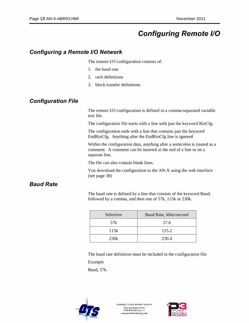
Baud Rate The baud rate is defined by a line that consists of the keyword Baud, followed by a comma, and then one of 57k, 115k or 230k.
Selection Baud Rate, kbits/second
57k 57.6
115k 115.2
230k 230.4
The baud rate definition must be included in the configuration file.
Example
Baud, 57k
AN-X-ABRIO-HMI Page 19
Racks Racks are defined by line that consist of the keyword Rack, followed by a comma, the racknumber in octal in the form 0oxx where xx is the rack number from 1 to 76 octal, a comma, the start quarter (1-4), a comma, and the end quarter (1-4).
Examples
Rack, 0o01,1,4
Rack, 0o07,1,1
The end quarter must be greater than or equal to the start quarter.
0 is not an allowed rack number.
There can be a maximum of 16 different rack numbers (not 16 separate rack definitions).
There must be at least one rack definition in the configuration file.
Block Transfers Block transfer definitions contain the block transfer type (read or write), the location (rack, I/O group and slot), the PLC-5 file address (file number and offset) where the HMI can access the data, and the block transfer length. The fields must be separated by commas.
btr, rack, I/O group, slot, PLC-5 integer file, offset, length
btw, rack, I/O group, slot, PLC-5 integer file, offset, length
The rack number is in the form 0oxx where xx is the rack number from 1 to 76 octal. The rack must have been previously defined in a rack definition.
The I/O group must be in the range 0 to 7.
The slot must be 0 or 1.
The PLC-5 file is always an integer (N) file. The file number can be from 0 to 999. The offset can be from 0 to 999. The offset + length cannot exceed 1000.
The block transfer length can be from 1 to 64.
The rack address must have been previously defined or the block transfer definition will produce an error.
Examples
btr,0o01,0,0,32,0,1
btw,0o01,0,0,32,0,1
Page 20 AN-X-ABRIO-HMI November 2011
Block Transfers by Length For compatibility with some existing PanelView applications, AN-X-ABRIO-HMI supports a block transfer by length mode, where multiple block transfers of different lengths are defined at the same I/O location (rack, I/O group and slot). When the remote I/O scanner requests a block transfer at that location, the AN-X uses the requested length to select which data to access.
The block transfer must be at the lowest address in the partial rack where the block transfer is found. For example, if the rack is a quarter rack, rack 1, starting at I/O group 2 (second quarter), any block transfers must be at rack 1, I/O group 2, slot 0.
If you are using block transfer by length mode, only one rack number can be defined in the configuration.
The configuration file must contain a line with the keyword BtByLen before the rack and block transfer definitions.
Sample Configuration
RioCfg, ; start of configuration
Baud, 57k6, ;define baud rate for 1771 IO network (57k6,115k2,230k4)
Rack, 0o01, 1, 4, ;define rack at octal 01, start quarter 1, end quarter 4
btr, 0o01, 0, 0, 31, 0, 64, ;define btr, rack 01, group 0, slot 0 -> N31:0, length is 64
btw, 0o01, 0, 0, 31, 128, 64, ;define btw, rack 01, group 0, slot 0 -> N31:128, length is 64
EndRioCfg,
Sample Block Transfer by Length Configuration
RioCfg, ; start of configuration
Baud, 57k, ;define baud rate for 1771 IO network
BtByLen, ;emulate SRIO configuration and map BT by len
Rack, 0o01, 1, 1, ;in BtByLen user can define only one rack
btr, 0o01, 0, 0, 31, 0, 1, ; each BTR definition must have a different length
btr, 0o01, 0, 0, 33, 0, 2, ; each BTR definition must have a different length
btw, 0o01, 0, 0, 33, 0, 1, ; each BTW must have a different length
btw, 0o01, 0, 0, 33, 3, 32 ; all BTs use group 0, slot 0
EndRioCfg
AN-X-ABRIO-HMI Page 21
Downloading Configurations To download a configuration to the AN-X-AB-RIO, start the web interface and select Automation Network/Configure RIO to Enet/IP to download a configuration file to the AN-X.
Page 22 AN-X-ABRIO-HMI November 2011
Accessing Data Configuration
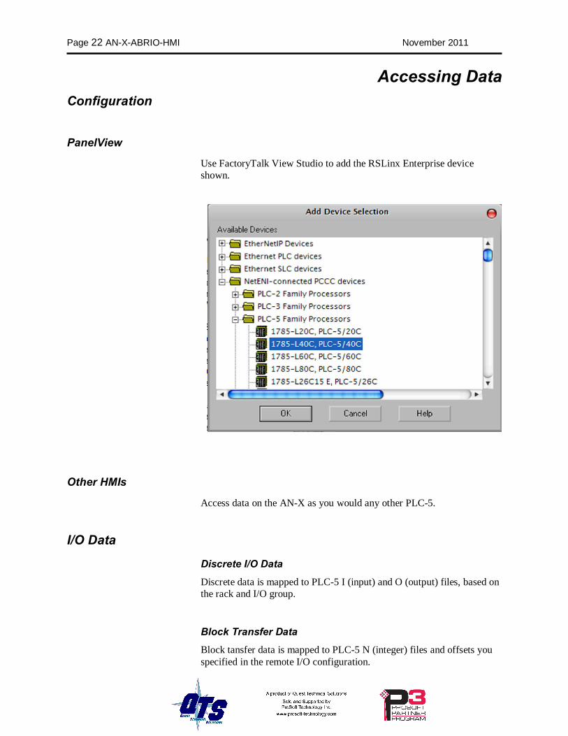
PanelView
Use FactoryTalk View Studio to add the RSLinx Enterprise device shown.
Other HMIs
Access data on the AN-X as you would any other PLC-5.
I/O Data
Discrete I/O Data Discrete data is mapped to PLC-5 I (input) and O (output) files, based on the rack and I/O group.
Block Transfer Data Block tansfer data is mapped to PLC-5 N (integer) files and offsets you specified in the remote I/O configuration.
AN-X-ABRIO-HMI Page 23
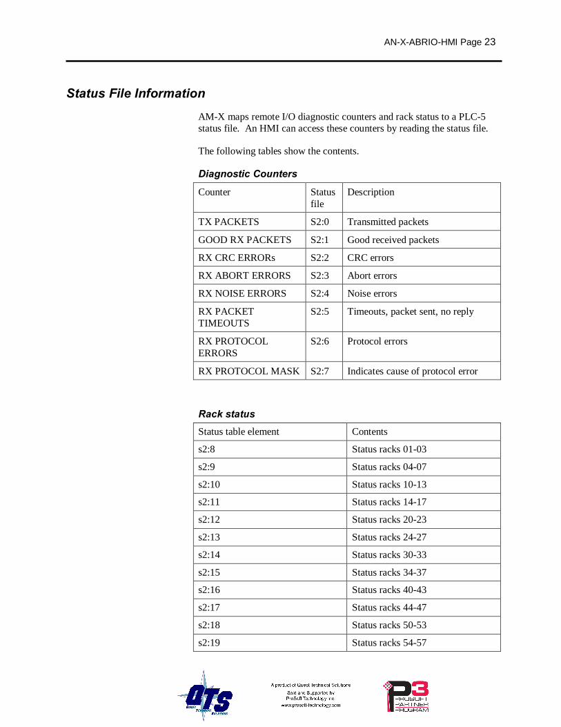
Status File Information
AM-X maps remote I/O diagnostic counters and rack status to a PLC-5 status file. An HMI can access these counters by reading the status file.
The following tables show the contents.
Diagnostic Counters
Counter Status file
Description
TX PACKETS S2:0 Transmitted packets
GOOD RX PACKETS S2:1 Good received packets
RX CRC ERRORs S2:2 CRC errors
RX ABORT ERRORS S2:3 Abort errors
RX NOISE ERRORS S2:4 Noise errors
RX PACKET TIMEOUTS
S2:5 Timeouts, packet sent, no reply
RX PROTOCOL ERRORS
S2:6 Protocol errors
RX PROTOCOL MASK S2:7 Indicates cause of protocol error
Rack status Status table element Contents
s2:8 Status racks 01-03
s2:9 Status racks 04-07
s2:10 Status racks 10-13
s2:11 Status racks 14-17
s2:12 Status racks 20-23
s2:13 Status racks 24-27
s2:14 Status racks 30-33
s2:15 Status racks 34-37
s2:16 Status racks 40-43
s2:17 Status racks 44-47
s2:18 Status racks 50-53
s2:19 Status racks 54-57

Page 24 AN-X-ABRIO-HMI November 2011
Status table element Contents
s2:20 Status racks 60-63
s2:21 Status racks 64-67
s2:22 Status racks 70-73
s2:23 Status racks 74-76
The rack status contains 4 bits per rack, with the low bit corresponding to a rack starting at I/O group 0, etc. The bit is 1 if the rack is being scanned and is 0 otherwise.
AN-X-ABRIO-HMI Page 25
Using AnxInit AnxInit is a 32-bit Windows application supplied with AN-X to perform the following functions:
• Locate and identify AN-X modules on the Ethernet network
• Select a specific AN-X for configuration
• Set the IP address and other Ethernet parameters for an AN-X
• Restart an AN-X in production mode
• Display information about the selected AN-X
• Read the kernel parameters for the selected AN-X
• Update the flash (low level firmware) on the selected AN-X
• Update the firmware on the selected AN-X
• Patch the firmware on the selected AN-X
In addition, it can be used to:
• clear the AnxInit log
• copy the contents of the log to the clipboard for use by another application. This is often useful for technical support
AnxInit Log AnxInit logs messages in its main window. These messages are often useful for determining the cause of errors or for technical support.
To clear the log, select Edit/ClearLog.
To copy the contents of the Log to the Windows clipboard so that they can be pasted into another application, select Edit/Copy.
Page 26 AN-X-ABRIO-HMI November 2011
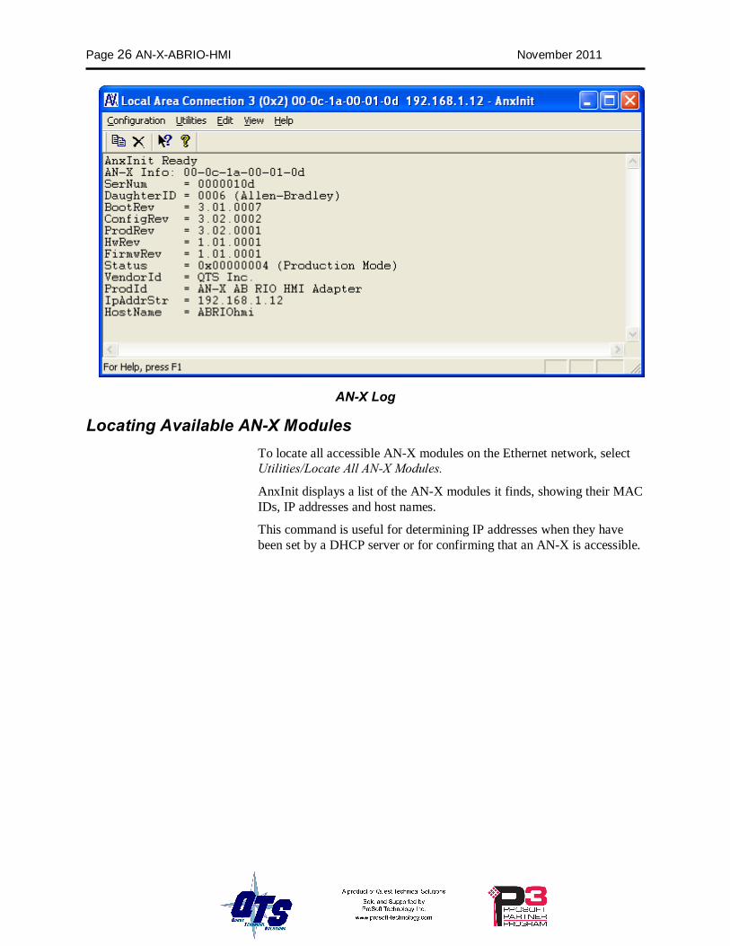
AN-X Log
Locating Available AN-X Modules To locate all accessible AN-X modules on the Ethernet network, select Utilities/Locate All AN-X Modules.
AnxInit displays a list of the AN-X modules it finds, showing their MAC IDs, IP addresses and host names.
This command is useful for determining IP addresses when they have been set by a DHCP server or for confirming that an AN-X is accessible.
AN-X-ABRIO-HMI Page 27
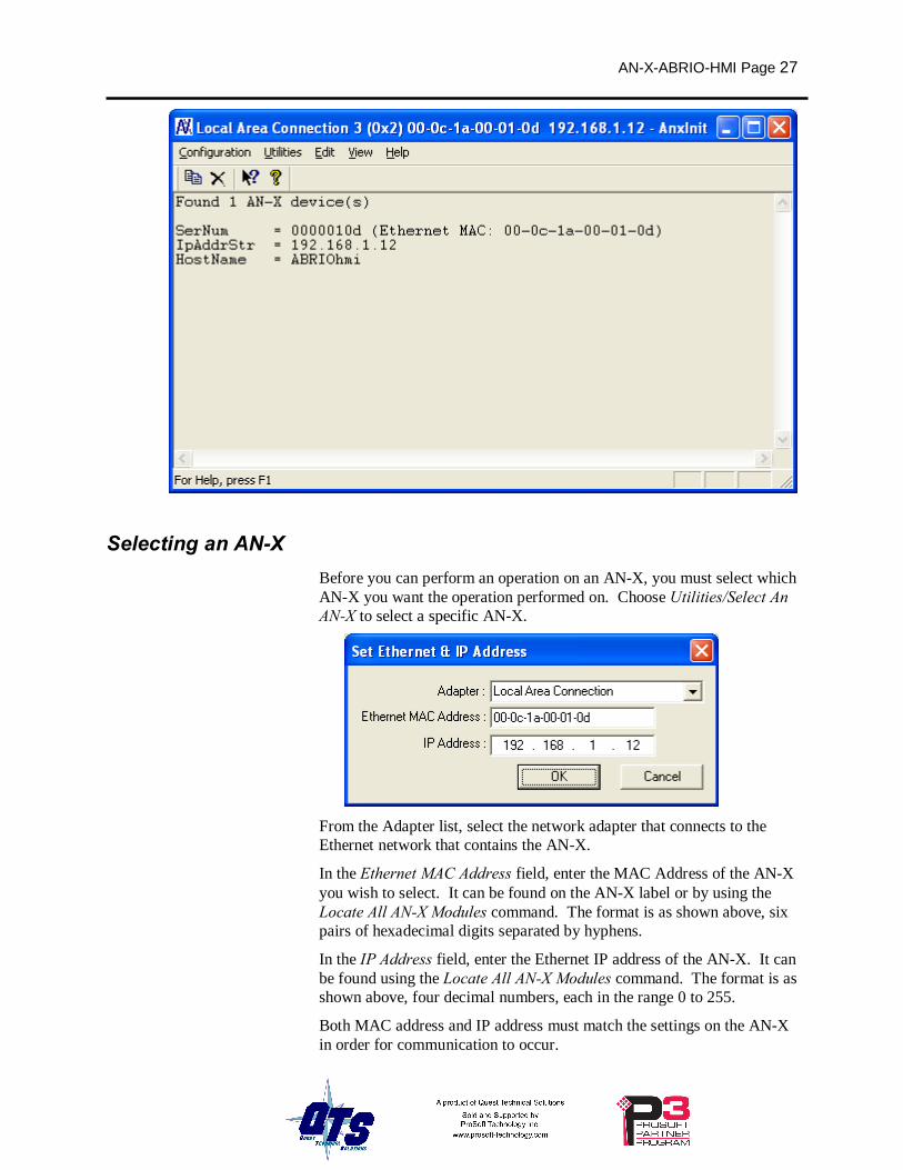
Selecting an AN-X Before you can perform an operation on an AN-X, you must select which AN-X you want the operation performed on. Choose Utilities/Select An AN-X to select a specific AN-X.
From the Adapter list, select the network adapter that connects to the Ethernet network that contains the AN-X.
In the Ethernet MAC Address field, enter the MAC Address of the AN-X you wish to select. It can be found on the AN-X label or by using the Locate All AN-X Modules command. The format is as shown above, six pairs of hexadecimal digits separated by hyphens.
In the IP Address field, enter the Ethernet IP address of the AN-X. It can be found using the Locate All AN-X Modules command. The format is as shown above, four decimal numbers, each in the range 0 to 255.
Both MAC address and IP address must match the settings on the AN-X in order for communication to occur.
Page 28 AN-X-ABRIO-HMI November 2011
Click OK to select the AN-X.
The title bar of AnxInit shows the MAC Address and IP Address of the currently selected AN-X.
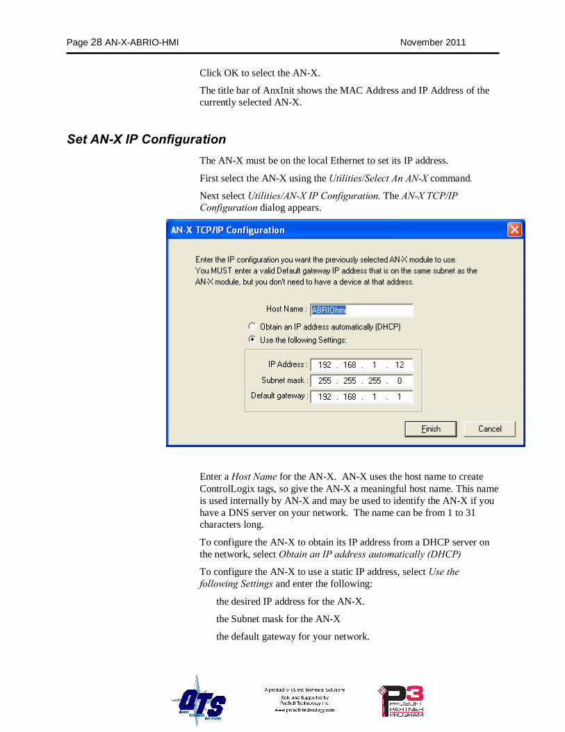
Set AN-X IP Configuration The AN-X must be on the local Ethernet to set its IP address.
First select the AN-X using the Utilities/Select An AN-X command.
Next select Utilities/AN-X IP Configuration. The AN-X TCP/IP Configuration dialog appears.
Enter a Host Name for the AN-X. AN-X uses the host name to create ControlLogix tags, so give the AN-X a meaningful host name. This name is used internally by AN-X and may be used to identify the AN-X if you have a DNS server on your network. The name can be from 1 to 31 characters long.
To configure the AN-X to obtain its IP address from a DHCP server on the network, select Obtain an IP address automatically (DHCP)
To configure the AN-X to use a static IP address, select Use the following Settings and enter the following:
• the desired IP address for the AN-X.
• the Subnet mask for the AN-X
• the default gateway for your network.
AN-X-ABRIO-HMI Page 29
You must enter a default gateway address that is valid for the subnet, even if there is no device at the gateway address on the network.
Click OK to complete the configuration.
Use the Utilities/Restart AN-X to restart the AN-X in production mode.
If you Cancel the Utilities/AN-X IP Configuration command, AN-X is left running in boot mode. Use the Utilities/Restart AN-X command to restart the AN-X.
Restart an AN-X Use the Utilities/Restart AN-X command to restart the currently selected AN-X in poduction mode.
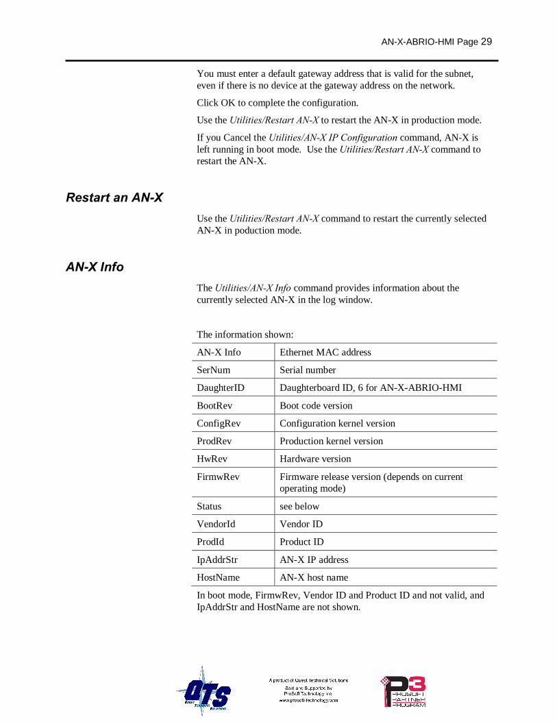
AN-X Info The Utilities/AN-X Info command provides information about the currently selected AN-X in the log window.
The information shown:
AN-X Info Ethernet MAC address
SerNum Serial number
DaughterID Daughterboard ID, 6 for AN-X-ABRIO-HMI
BootRev Boot code version
ConfigRev Configuration kernel version
ProdRev Production kernel version
HwRev Hardware version
FirmwRev Firmware release version (depends on current operating mode)
Status see below
VendorId Vendor ID
ProdId Product ID
IpAddrStr AN-X IP address
HostName AN-X host name
In boot mode, FirmwRev, Vendor ID and Product ID and not valid, and IpAddrStr and HostName are not shown.
Page 30 AN-X-ABRIO-HMI November 2011
Possible status values are:
Value Meaning
1 Boot mode
2 Configuration mode
4 Production mode
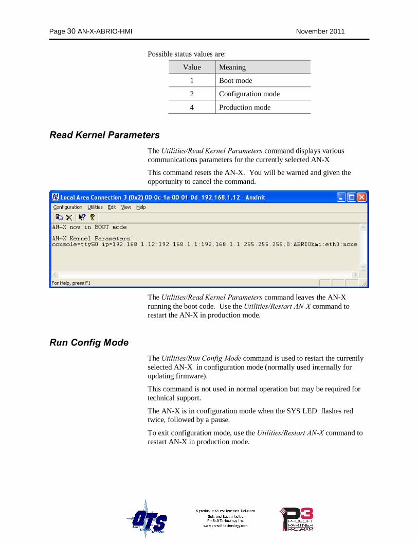
Read Kernel Parameters The Utilities/Read Kernel Parameters command displays various communications parameters for the currently selected AN-X
This command resets the AN-X. You will be warned and given the opportunity to cancel the command.
The Utilities/Read Kernel Parameters command leaves the AN-X running the boot code. Use the Utilities/Restart AN-X command to restart the AN-X in production mode.
Run Config Mode The Utilities/Run Config Mode command is used to restart the currently selected AN-X in configuration mode (normally used internally for updating firmware).
This command is not used in normal operation but may be required for technical support.
The AN-X is in configuration mode when the SYS LED flashes red twice, followed by a pause.
To exit configuration mode, use the Utilities/Restart AN-X command to restart AN-X in production mode.
AN-X-ABRIO-HMI Page 31
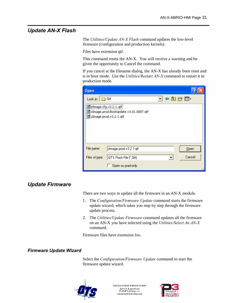
Update AN-X Flash The Utilities/Update AN-X Flash command updates the low-level firmware (configuration and production kernels).
Files have extension qtf.
This command resets the AN-X. You will receive a warning and be given the opportunity to Cancel the command.
If you cancel at the filename dialog, the AN-X has already been reset and is in boot mode. Use the Utilities/Restart AN-X command to restart it in production mode.
Update Firmware There are two ways to update all the firmware in an AN-X module.
1. The Configuration/Firmware Update command starts the firmware update wizard, which takes you step by step through the firmware update process.
2. The Utilities/Update Firmware command updates all the firmware on an AN-X you have selected using the Utilities/Select An AN-X command.
Firmware files have extension bin.
Firmware Update Wizard
Select the Configuration/Firmware Update command to start the firmware update wizard.
Page 32 AN-X-ABRIO-HMI November 2011
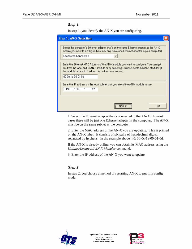
Step 1: In step 1, you identify the AN-X you are configuring.
1. Select the Ethernet adapter that’s connected to the AN-X. In most cases there will be just one Ethernet adapter in the computer. The AN-X must be on the same subnet as the computer.
2. Enter the MAC address of the AN-X you are updating. This is printed on the AN-X label. It consists of six pairs of hexadecimal digits, separated by hyphens. In the example above, it’s 00-0c-1a-00-01-0d.
If the AN-X is already online, you can obtain its MAC address using the Utilities/Locate All AN-X Modules command.
3. Enter the IP address of the AN-X you want to update
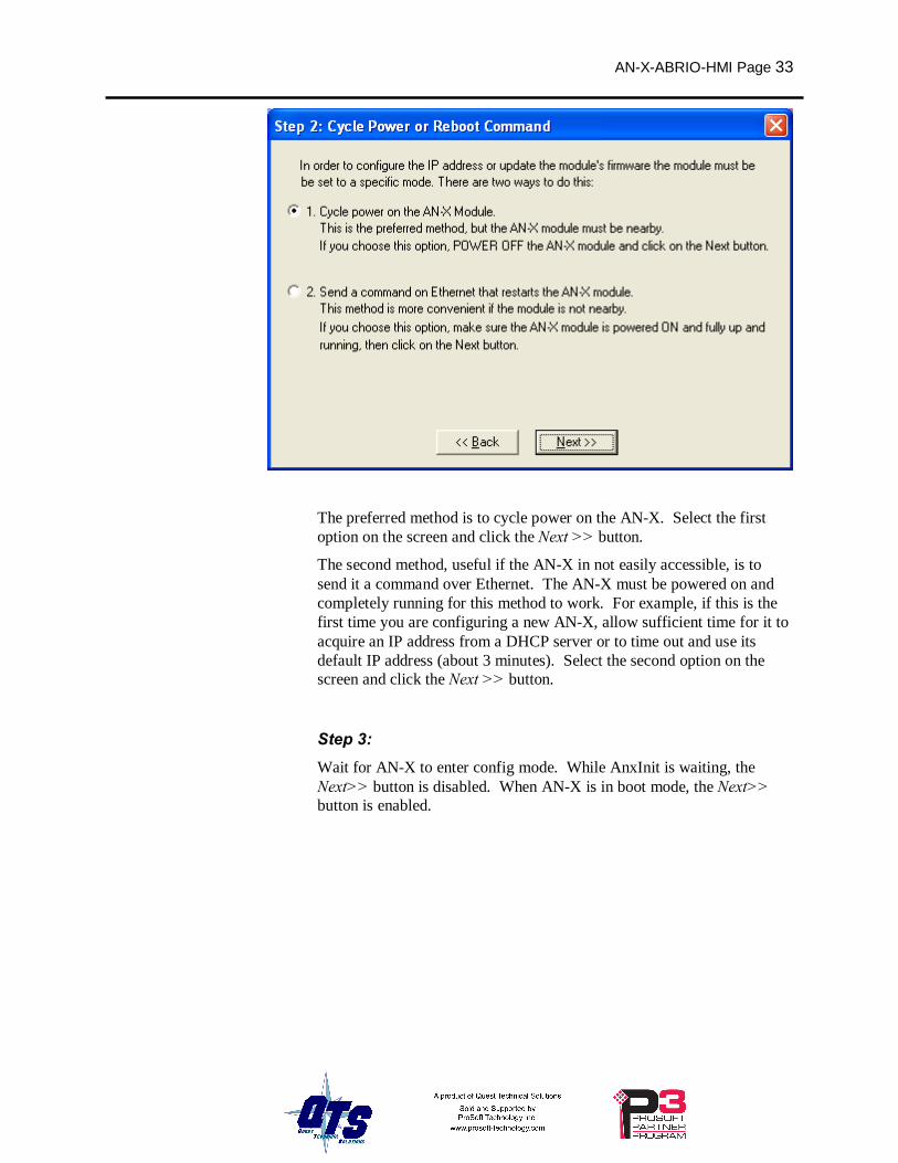
Step 2 In step 2, you choose a method of restarting AN-X to put it in config mode.
AN-X-ABRIO-HMI Page 33
The preferred method is to cycle power on the AN-X. Select the first option on the screen and click the Next >> button.
The second method, useful if the AN-X in not easily accessible, is to send it a command over Ethernet. The AN-X must be powered on and completely running for this method to work. For example, if this is the first time you are configuring a new AN-X, allow sufficient time for it to acquire an IP address from a DHCP server or to time out and use its default IP address (about 3 minutes). Select the second option on the screen and click the Next >> button.
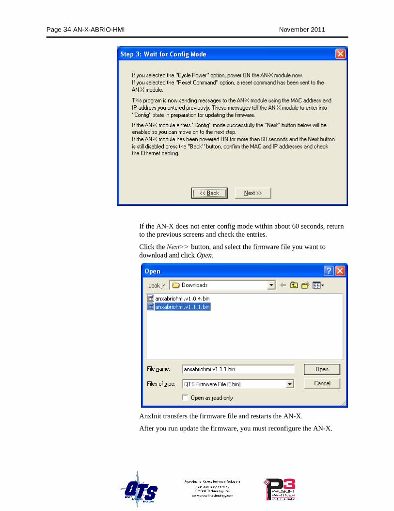
Step 3: Wait for AN-X to enter config mode. While AnxInit is waiting, the Next>> button is disabled. When AN-X is in boot mode, the Next>> button is enabled.
Page 34 AN-X-ABRIO-HMI November 2011
If the AN-X does not enter config mode within about 60 seconds, return to the previous screens and check the entries.
Click the Next>> button, and select the firmware file you want to download and click Open.
AnxInit transfers the firmware file and restarts the AN-X.
After you run update the firmware, you must reconfigure the AN-X.
AN-X-ABRIO-HMI Page 35
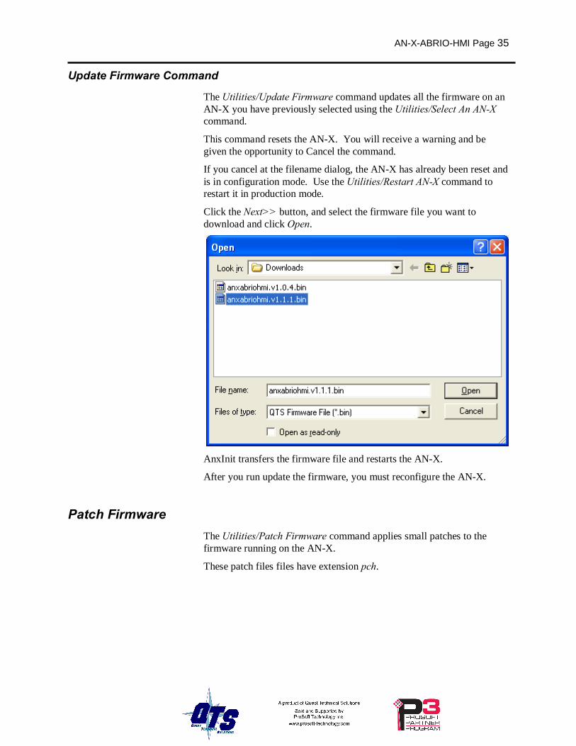
Update Firmware Command
The Utilities/Update Firmware command updates all the firmware on an AN-X you have previously selected using the Utilities/Select An AN-X command.
This command resets the AN-X. You will receive a warning and be given the opportunity to Cancel the command.
If you cancel at the filename dialog, the AN-X has already been reset and is in configuration mode. Use the Utilities/Restart AN-X command to restart it in production mode.
Click the Next>> button, and select the firmware file you want to download and click Open.
AnxInit transfers the firmware file and restarts the AN-X.
After you run update the firmware, you must reconfigure the AN-X.
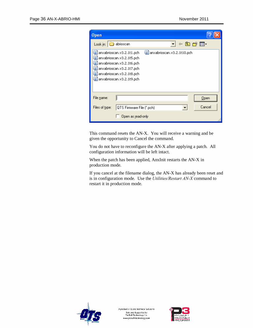
Patch Firmware The Utilities/Patch Firmware command applies small patches to the firmware running on the AN-X.
These patch files files have extension pch.
Page 36 AN-X-ABRIO-HMI November 2011
This command resets the AN-X. You will receive a warning and be given the opportunity to Cancel the command.
You do not have to reconfigure the AN-X after applying a patch. All configuration information will be left intact.
When the patch has been applied, AnxInit restarts the AN-X in production mode.
If you cancel at the filename dialog, the AN-X has already been reset and is in configuration mode. Use the Utilities/Restart AN-X command to restart it in production mode.
AN-X-ABRIO-HMI Page 37
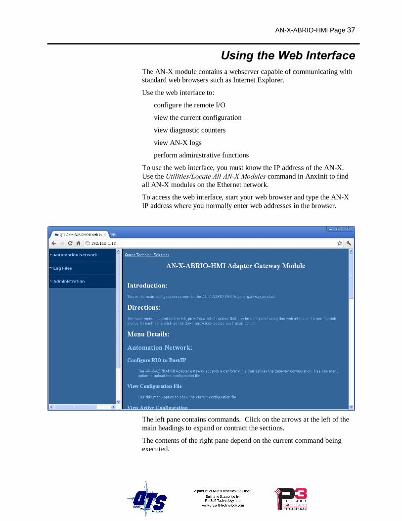
Using the Web Interface The AN-X module contains a webserver capable of communicating with standard web browsers such as Internet Explorer.
Use the web interface to:
• configure the remote I/O
• view the current configuration
• view diagnostic counters
• view AN-X logs
• perform administrative functions
To use the web interface, you must know the IP address of the AN-X. Use the Utilities/Locate All AN-X Modules command in AnxInit to find all AN-X modules on the Ethernet network.
To access the web interface, start your web browser and type the AN-X IP address where you normally enter web addresses in the browser.
The left pane contains commands. Click on the arrows at the left of the main headings to expand or contract the sections.
The contents of the right pane depend on the current command being executed.
Page 38 AN-X-ABRIO-HMI November 2011
Automation Network
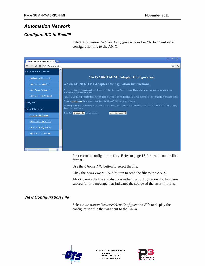
Configure RIO to Enet/IP
Select Automation Network/Configure RIO to Enet/IP to download a configuration file to the AN-X.
First create a configuration file. Refer to page 18 for details on the file format.
Use the Choose File button to select the file.
Click the Send File to AN-X button to send the file to the AN-X.
AN-X parses the file and displays either the configuration if it has been successful or a message that indicates the source of the error if it fails.
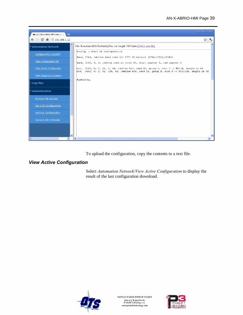
View Configuration File
Select Automation Network/View Configuration File to display the configuration file that was sent to the AN-X.
AN-X-ABRIO-HMI Page 39
To upload the configuration, copy the contents to a text file.
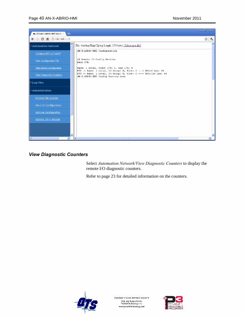
View Active Configuration
Select Automation Network/View Active Configuration to display the result of the last configuration download.
Page 40 AN-X-ABRIO-HMI November 2011
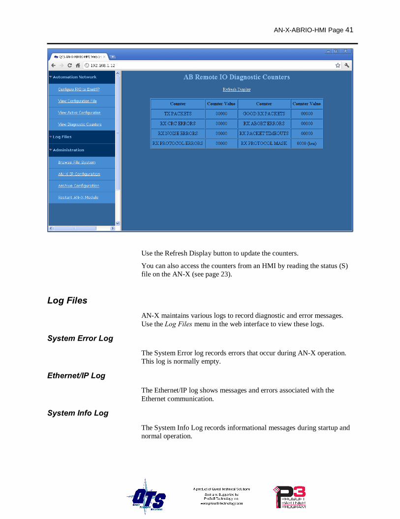
View Diagnostic Counters
Select Automation Network/View Diagnostic Counters to display the remote I/O diagnostic counters.
Refer to page 23 for detailed information on the counters.
AN-X-ABRIO-HMI Page 41
Use the Refresh Display button to update the counters.
You can also access the counters from an HMI by reading the status (S) file on the AN-X (see page 23).
Log Files AN-X maintains various logs to record diagnostic and error messages. Use the Log Files menu in the web interface to view these logs.
System Error Log
The System Error log records errors that occur during AN-X operation. This log is normally empty.
Ethernet/IP Log
The Ethernet/IP log shows messages and errors associated with the Ethernet communication.
System Info Log
The System Info Log records informational messages during startup and normal operation.
Page 42 AN-X-ABRIO-HMI November 2011
View All Logs
Use View All Logs to list and view all the AN-X logs. To view a log file, double click on the file name.
Administration Menu The Administration Menu is used to set the AN-X IP address and to view and edit files on AN-X. The file edit function is password protected and is used only for AN-X technical support.
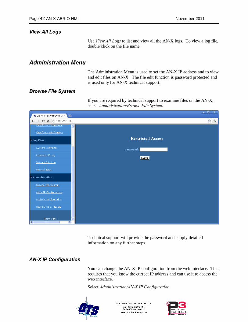
Browse File System
If you are required by technical support to examine files on the AN-X, select Administration/Browse File System.
Technical support will provide the password and supply detailed information on any further steps.
AN-X IP Configuration
You can change the AN-X IP configuration from the web interface. This requires that you know the currect IP address and can use it to access the web interface.
Select Administration/AN-X IP Configuration.
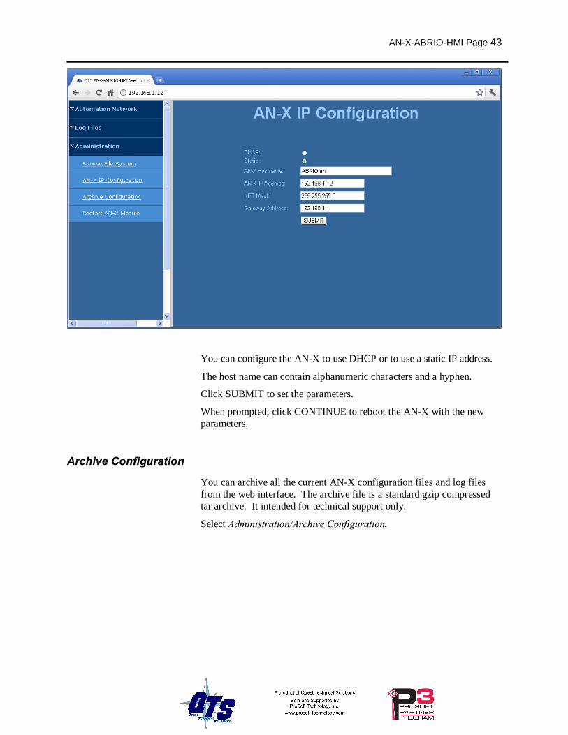
AN-X-ABRIO-HMI Page 43
You can configure the AN-X to use DHCP or to use a static IP address.
The host name can contain alphanumeric characters and a hyphen.
Click SUBMIT to set the parameters.
When prompted, click CONTINUE to reboot the AN-X with the new parameters.
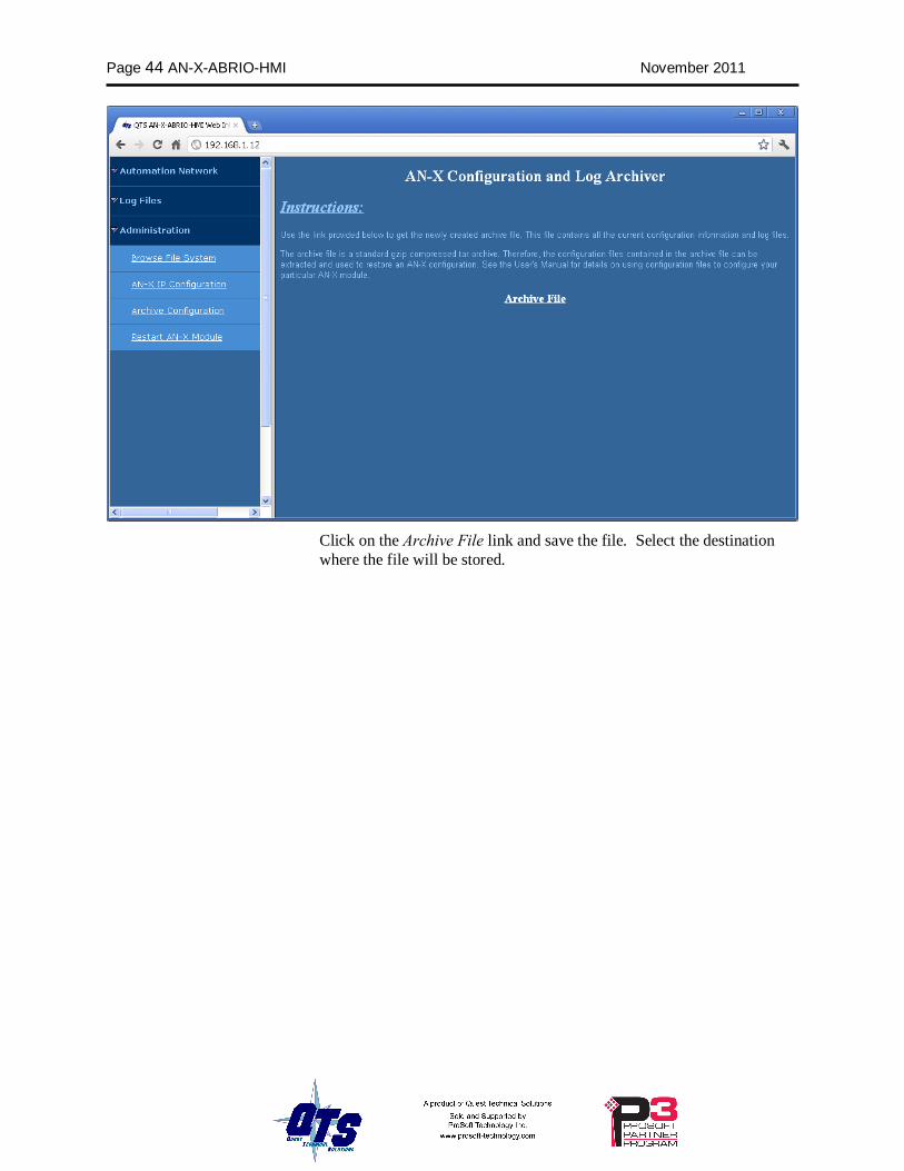
Archive Configuration
You can archive all the current AN-X configuration files and log files from the web interface. The archive file is a standard gzip compressed tar archive. It intended for technical support only.
Select Administration/Archive Configuration.
Page 44 AN-X-ABRIO-HMI November 2011
Click on the Archive File link and save the file. Select the destination where the file will be stored.
AN-X-ABRIO-HMI Page 45
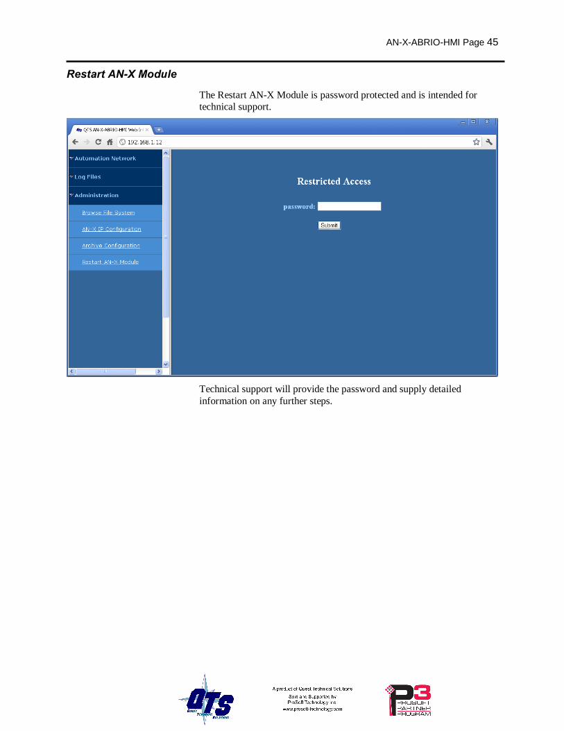
Restart AN-X Module
The Restart AN-X Module is password protected and is intended for technical support.
Technical support will provide the password and supply detailed information on any further steps.
Page 46 AN-X-ABRIO-HMI November 2011
Troubleshooting LEDs
The AN-X-ABRIO-HMI has LEDs that indicate the state of the Ethernet connection, the overall module state and the connection to the remote I/O network.
Ethernet LEDs
There are two LEDs that indicate the state of the Ethernet connection.
The orange LED, labelled 100, is on if the link is running at 100 Mbits/second and is off otherwise.
The green Link/Act LED is off if the link is inactive and is on if the link is active. If activity is detected, the link blinks at 30 ms intervals and continues blinking as long as activity is present.
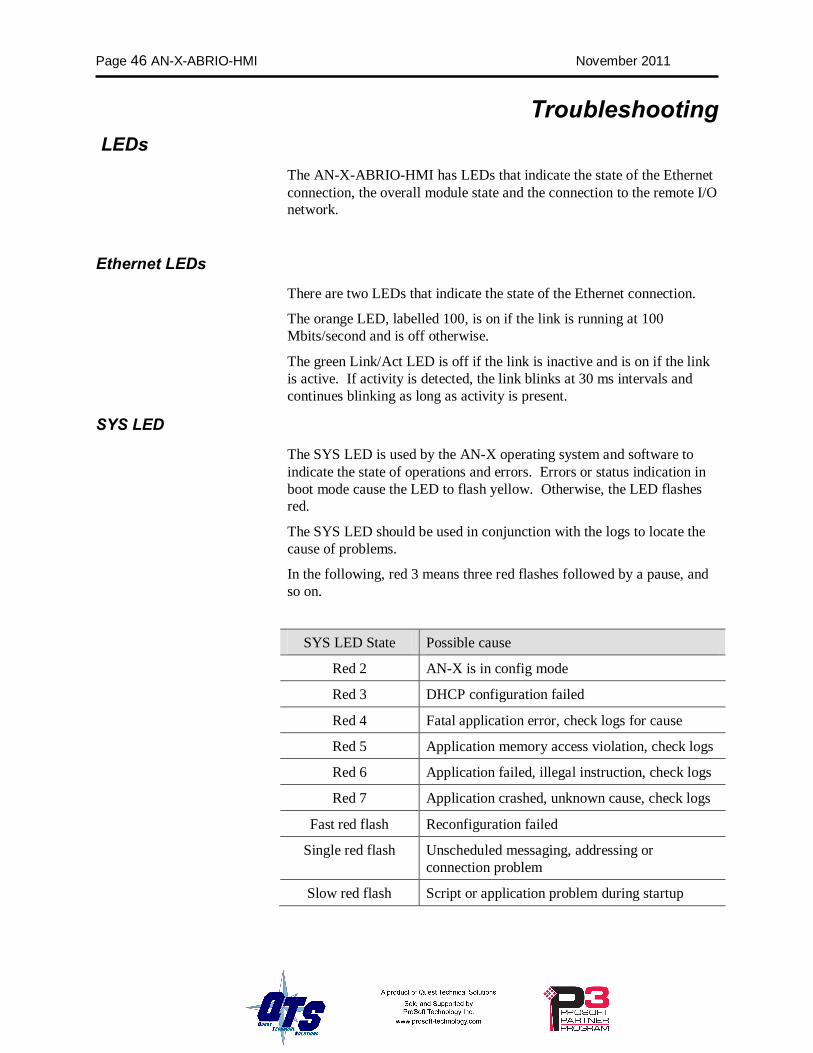
SYS LED
The SYS LED is used by the AN-X operating system and software to indicate the state of operations and errors. Errors or status indication in boot mode cause the LED to flash yellow. Otherwise, the LED flashes red.
The SYS LED should be used in conjunction with the logs to locate the cause of problems.
In the following, red 3 means three red flashes followed by a pause, and so on.
SYS LED State Possible cause
Red 2 AN-X is in config mode
Red 3 DHCP configuration failed
Red 4 Fatal application error, check logs for cause
Red 5 Application memory access violation, check logs
Red 6 Application failed, illegal instruction, check logs
Red 7 Application crashed, unknown cause, check logs
Fast red flash Reconfiguration failed
Single red flash Unscheduled messaging, addressing or connection problem
Slow red flash Script or application problem during startup
AN-X-ABRIO-HMI Page 47
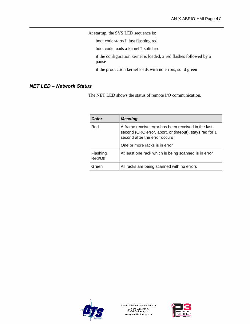
At startup, the SYS LED sequence is:
• boot code starts – fast flashing red
• boot code loads a kernel – solid red
• if the configuration kernel is loaded, 2 red flashes followed by a pause
• if the production kernel loads with no errors, solid green
NET LED – Network Status
The NET LED shows the status of remote I/O communication.
Color Meaning
Red A frame receive error has been received in the last second (CRC error, abort, or timeout), stays red for 1 second after the error occurs
One or more racks is in error
Flashing Red/Off
At least one rack which is being scanned is in error
Green All racks are being scanned with no errors
Page 48 AN-X-ABRIO-HMI November 2011
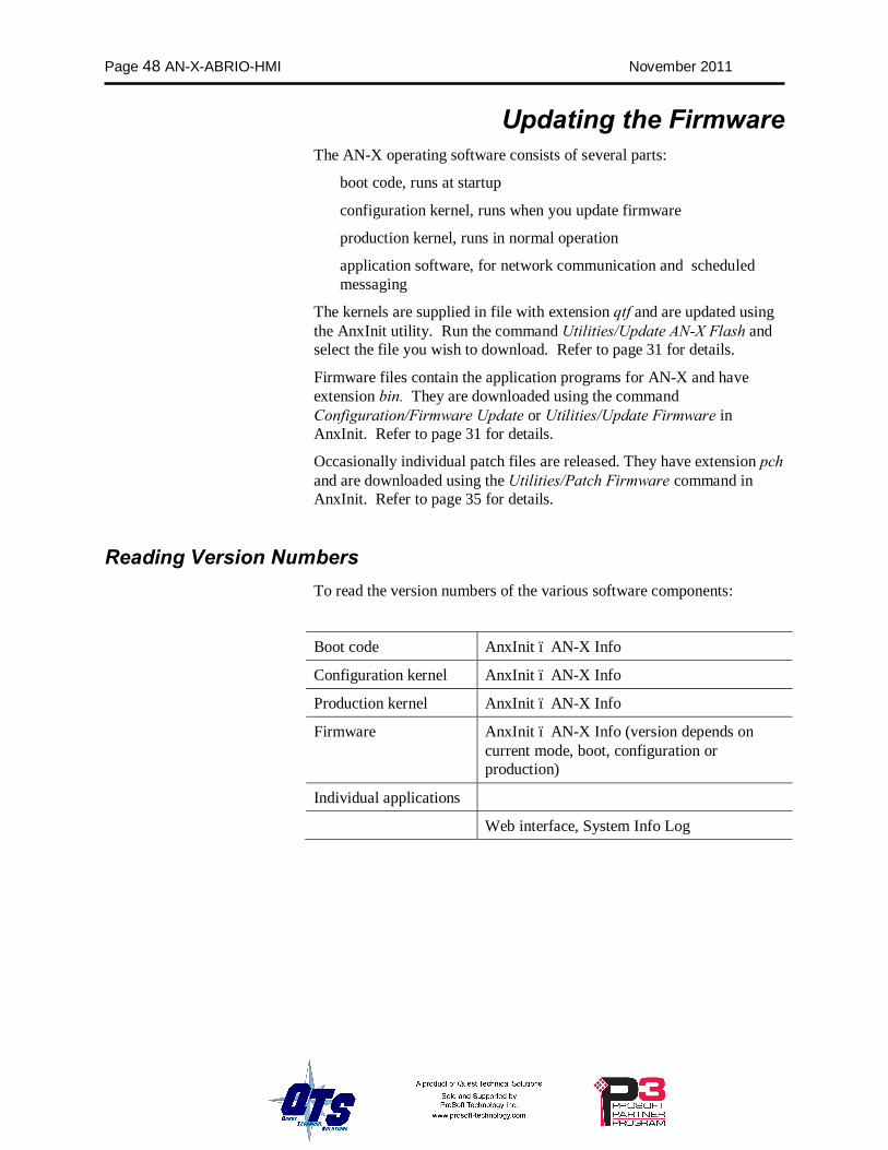
Updating the Firmware The AN-X operating software consists of several parts:
• boot code, runs at startup
• configuration kernel, runs when you update firmware
• production kernel, runs in normal operation
• application software, for network communication and scheduled messaging
The kernels are supplied in file with extension qtf and are updated using the AnxInit utility. Run the command Utilities/Update AN-X Flash and select the file you wish to download. Refer to page 31 for details.
Firmware files contain the application programs for AN-X and have extension bin. They are downloaded using the command Configuration/Firmware Update or Utilities/Update Firmware in AnxInit. Refer to page 31 for details.
Occasionally individual patch files are released. They have extension pch and are downloaded using the Utilities/Patch Firmware command in AnxInit. Refer to page 35 for details.
Reading Version Numbers To read the version numbers of the various software components:
Boot code AnxInit – AN-X Info
Configuration kernel AnxInit – AN-X Info
Production kernel AnxInit – AN-X Info
Firmware AnxInit – AN-X Info (version depends on current mode, boot, configuration or production)
Individual applications
Web interface, System Info Log
AN-X-ABRIO-HMI Page 49
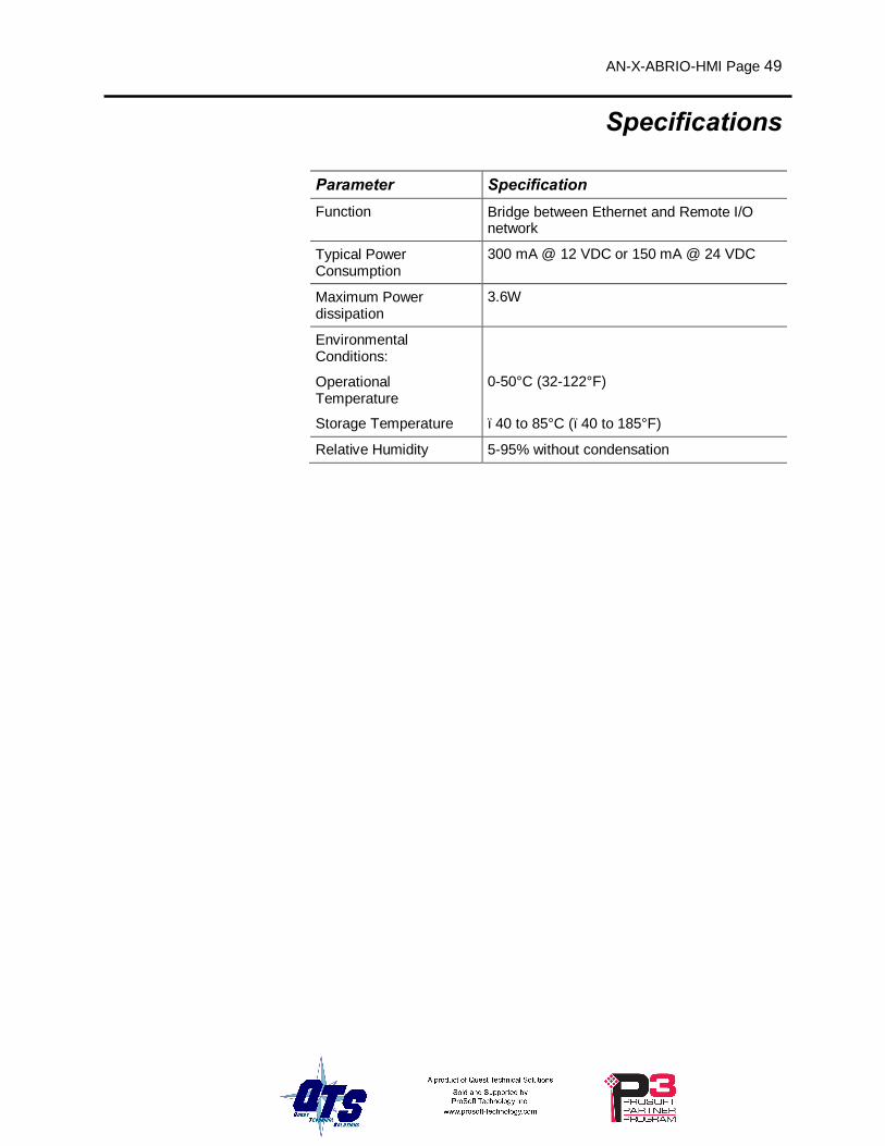
Specifications
Parameter Specification Function Bridge between Ethernet and Remote I/O
network
Typical Power Consumption
300 mA @ 12 VDC or 150 mA @ 24 VDC
Maximum Power dissipation
3.6W
Environmental Conditions:
Operational Temperature
0-50°C (32-122°F)
Storage Temperature –40 to 85°C (–40 to 185°F)
Relative Humidity 5-95% without condensation

Page 50 AN-X-ABRIO-HMI November 2011
Support
How to Contact Us: Sales and Support
Sales and Technical Support for this product are provided by ProSoft Technology. Contact our worldwide Sales or Technical Support teams directly by phone or email:
Asia Pacific
+603.7724.2080, [email protected]
Europe – Middle East – Africa
+33 (0) 5.34.36.87.20, [email protected]
North America
+1.661.716.5100, [email protected]
Latin America (Sales only)
+1.281.298.9109, [email protected].

AN-X-ABRIO-HMI Page 51
Warranty Quest Technical Solutions warrants its products to be free from defects in workmanship or material under normal use and service for three years after date of shipment. Quest Technical Solutions will repair or replace without charge any equipment found to be defective during the warranty period. Final determination of the nature and responsibility for defective or damaged equipment will be made by Quest Technical Solutions personnel.
All warranties hereunder are contingent upon proper use in the application for which the product was intended and do not cover products which have been modified or repaired without Quest Technical Solutions approval or which have been subjected to accident, improper maintenance, installation or application, or on which original identification marks have been removed or altered. This Limited Warranty also will not apply to interconnecting cables or wires, consumables nor to any damage resulting from battery leakage.
In all cases Quest Technical Solutions’ responsibility and liability under this warranty shall be limited to the cost of the equipment. The purchaser must obtain shipping instructions for the prepaid return of any item under this Warranty provision and compliance with such instruction shall be a condition of this warranty.
Except for the express warranty stated above Quest Technical Solutions disclaims all warranties with regard to the products sold hereunder including all implied warranties of merchantability and fitness and the express warranties stated herein are in lieu of all obligations or liabilities on the part of Quest Technical Solutions for damages including, but not limited to, consequential damages arising out of/or in connection with the use or performance of the Product.


![FA Equipment for Beginners(HMIs) THA.ppt [互換モード] · CPU PLC HMI PLC I-IMI "HMI HMI HMI FA Equipment for Beginners(HMIs) THA 1.1 HMI](https://img.pdfslide.net/doc/110x75/5bd44ddf09d3f209338bbd79/fa-equipment-for-beginnershmis-thappt-cpu-plc-hmi-plc-i-imi.jpg)