Embed Size (px)
Citation preview

Copyright Notice
©2006 IEEE. Personal use of this material is permitted. However, permission to reprint/republish this material for advertising or promotional purposes or for creating new collective works for resale or redistribution to servers or lists, or to reuse any copyrighted component of this work in other works must be ob-tained from the IEEE.
Analog Circuits for Symbol-LikelihoodComputation
Matthias Frey and Hans-Andrea LoeligerSignal & Information Processing Laboratory (ISI),
ETH Zentrum, CH-8092 Zurich, Switzerland{frey, loeliger}@isi.ee.ethz.ch
Patrick MerkliSensirion AG,
CH-8712 Staefa ZH, [email protected]
Abstract—New analog circuits are presented to convert theoutput of a matched filter into symbol- and bit-likelihoodssuitable as input to analog decoders for error correcting codes.The new circuits can be adapted to many constellations includingpulse amplitude modulation (PAM) and quadrature amplitudemodulation (QAM) and for arbitrary bit-to-symbol mappings.In contrast to a previously published circuit these new circuitscompute exact probabilities and they are more versatile.
I. INTRODUCTION
This paper addresses a problem that arises in the context ofanalog decoders for error correcting codes [1]–[4].
Consider the standard discrete-time model of the additivewhite Gaussian noise (AWGN) channel. Let X be the (real orcomplex) transmitted signal, which is taken from some finiteconstellation A = {A0, . . . , AM−1}. The received symbol Yis
Y = X + Z, (1)
where Z is a zero-mean (real or complex) Gaussian randomvariable with variance σ2
Z that is independent of X . Let f(y|x)be the conditional probability density of Y given X = x.
In this paper, we present novel analog circuits for thecomputation of f(y|x). The input to the circuits is the (real orcomplex) number Y = y; the output of the circuits consistsof currents proportional to the M real numbers
f(y|X = A0), . . . , f(y|X = AM−1)
in a form suitable for analog decoders. The circuits are easilyextended to produce bit likelihoods (“soft bits”) for arbitrarybit-to-symbol mappings.
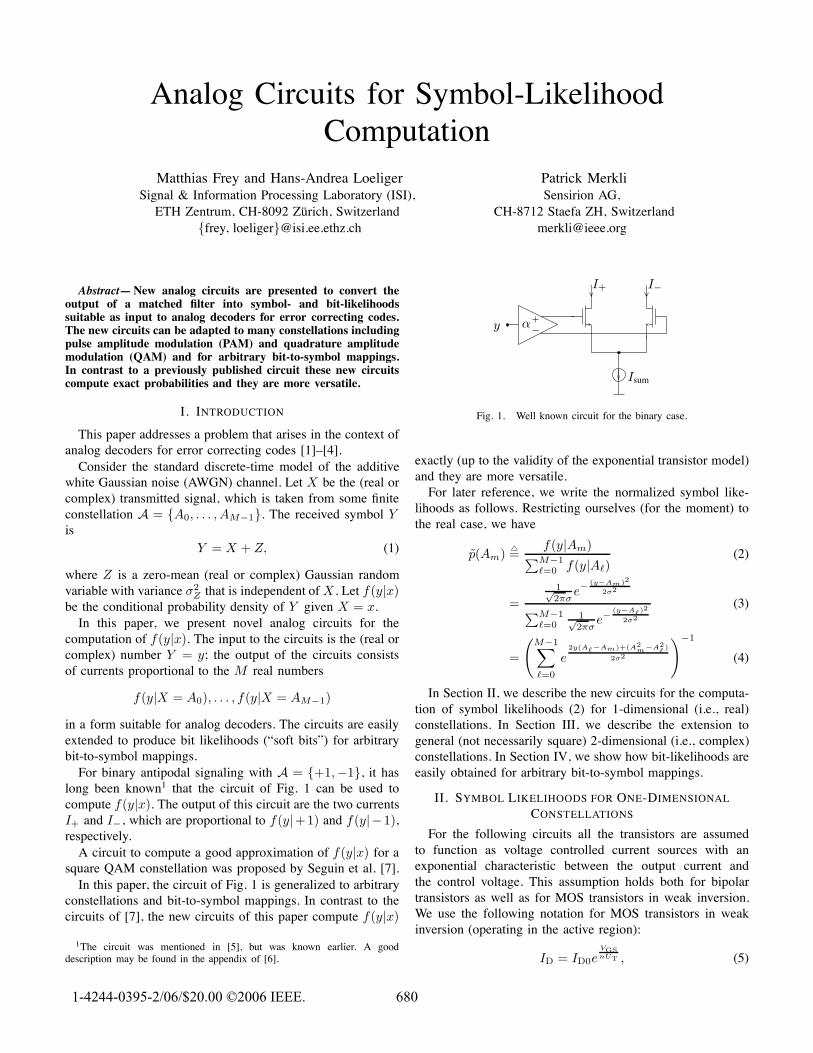
For binary antipodal signaling with A = {+1,−1}, it haslong been known1 that the circuit of Fig. 1 can be used tocompute f(y|x). The output of this circuit are the two currentsI+ and I−, which are proportional to f(y|+1) and f(y|−1),respectively.
A circuit to compute a good approximation of f(y|x) for asquare QAM constellation was proposed by Seguin et al. [7].
In this paper, the circuit of Fig. 1 is generalized to arbitraryconstellations and bit-to-symbol mappings. In contrast to thecircuits of [7], the new circuits of this paper compute f(y|x)
1The circuit was mentioned in [5], but was known earlier. A gooddescription may be found in the appendix of [6].
Isum
I+ I−
y α
Fig. 1. Well known circuit for the binary case.
exactly (up to the validity of the exponential transistor model)and they are more versatile.
For later reference, we write the normalized symbol like-lihoods as follows. Restricting ourselves (for the moment) tothe real case, we have
p(Am) �=f(y|Am)∑M−1
�=0 f(y|A�)(2)
=1√2πσ
e−(y−Am)2
2σ2
∑M−1�=0
1√2πσ
e−(y−A�)2
2σ2
(3)
=
(M−1∑�=0
e2y(A�−Am)+(A2
m−A2� )
2σ2
)−1
(4)
In Section II, we describe the new circuits for the computa-tion of symbol likelihoods (2) for 1-dimensional (i.e., real)constellations. In Section III, we describe the extension togeneral (not necessarily square) 2-dimensional (i.e., complex)constellations. In Section IV, we show how bit-likelihoods areeasily obtained for arbitrary bit-to-symbol mappings.
II. SYMBOL LIKELIHOODS FOR ONE-DIMENSIONAL
CONSTELLATIONS
For the following circuits all the transistors are assumedto function as voltage controlled current sources with anexponential characteristic between the output current andthe control voltage. This assumption holds both for bipolartransistors as well as for MOS transistors in weak inversion.We use the following notation for MOS transistors in weakinversion (operating in the active region):
ID = ID0eVGSnUT , (5)
1-4244-0395-2/06/$20.00 ©2006 IEEE. 680
where ID is the drain current, ID0 is a technology-dependentconstant, VGS is the gate-source voltage, n the slope-factor ofa MOS transistor and UT the thermal voltage [8].
Isum
I0 I1
y
αM−1y + VM−1α0y + V0 α1y + V1 α2y + V2
I2 IM−1
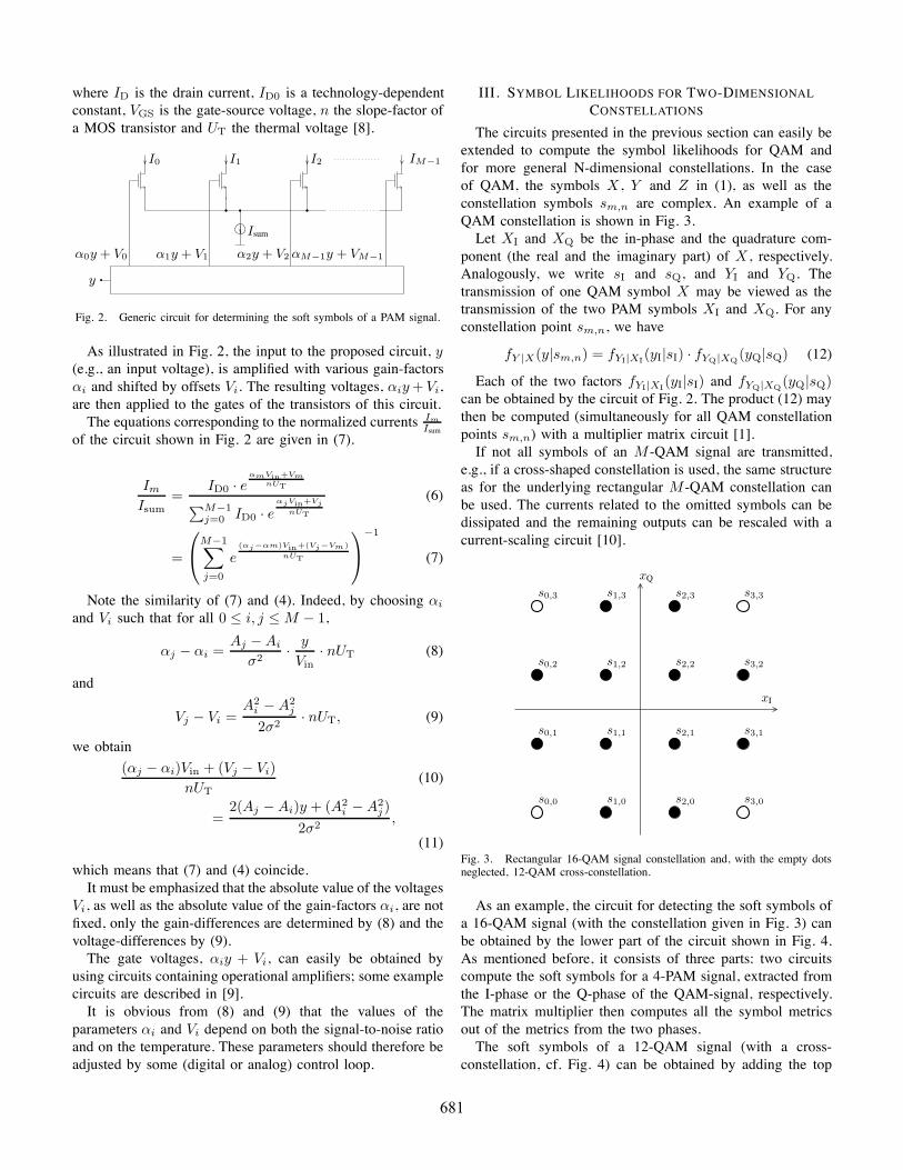
Fig. 2. Generic circuit for determining the soft symbols of a PAM signal.
As illustrated in Fig. 2, the input to the proposed circuit, y(e.g., an input voltage), is amplified with various gain-factorsαi and shifted by offsets Vi. The resulting voltages, αiy + Vi,are then applied to the gates of the transistors of this circuit.
The equations corresponding to the normalized currents Im
Isum
of the circuit shown in Fig. 2 are given in (7).
Im
Isum=
ID0 · eαmVin+Vm
nUT∑M−1j=0 ID0 · e
αjVin+VjnUT
(6)
=
⎛⎝M−1∑
j=0
e(αj−αm)Vin+(Vj−Vm)
nUT
⎞⎠
−1
(7)
Note the similarity of (7) and (4). Indeed, by choosing αi
and Vi such that for all 0 ≤ i, j ≤ M − 1,
αj − αi =Aj − Ai
σ2· y
Vin· nUT (8)
and
Vj − Vi =A2
i − A2j
2σ2· nUT, (9)
we obtain
(αj − αi)Vin + (Vj − Vi)nUT
(10)
=2(Aj − Ai)y + (A2
i − A2j)
2σ2,
(11)
which means that (7) and (4) coincide.It must be emphasized that the absolute value of the voltages
Vi, as well as the absolute value of the gain-factors αi, are notfixed, only the gain-differences are determined by (8) and thevoltage-differences by (9).
The gate voltages, αiy + Vi, can easily be obtained byusing circuits containing operational amplifiers; some examplecircuits are described in [9].
It is obvious from (8) and (9) that the values of theparameters αi and Vi depend on both the signal-to-noise ratioand on the temperature. These parameters should therefore beadjusted by some (digital or analog) control loop.
III. SYMBOL LIKELIHOODS FOR TWO-DIMENSIONAL
CONSTELLATIONS
The circuits presented in the previous section can easily beextended to compute the symbol likelihoods for QAM andfor more general N-dimensional constellations. In the caseof QAM, the symbols X , Y and Z in (1), as well as theconstellation symbols sm,n are complex. An example of aQAM constellation is shown in Fig. 3.
Let XI and XQ be the in-phase and the quadrature com-ponent (the real and the imaginary part) of X , respectively.Analogously, we write sI and sQ, and YI and YQ. Thetransmission of one QAM symbol X may be viewed as thetransmission of the two PAM symbols XI and XQ. For anyconstellation point sm,n, we have
fY |X(y|sm,n) = fYI|XI(yI|sI) · fYQ|XQ(yQ|sQ) (12)
Each of the two factors fYI|XI(yI|sI) and fYQ|XQ(yQ|sQ)can be obtained by the circuit of Fig. 2. The product (12) maythen be computed (simultaneously for all QAM constellationpoints sm,n) with a multiplier matrix circuit [1].
If not all symbols of an M -QAM signal are transmitted,e.g., if a cross-shaped constellation is used, the same structureas for the underlying rectangular M -QAM constellation canbe used. The currents related to the omitted symbols can bedissipated and the remaining outputs can be rescaled with acurrent-scaling circuit [10].
s0,0
s0,1
s0,2
s0,3
s1,0
s1,1
s1,2
s1,3
s2,0
s2,1
s2,2
s2,3
s3,0
s3,1
s3,2
s3,3
xQ
xI
Fig. 3. Rectangular 16-QAM signal constellation and, with the empty dotsneglected, 12-QAM cross-constellation.
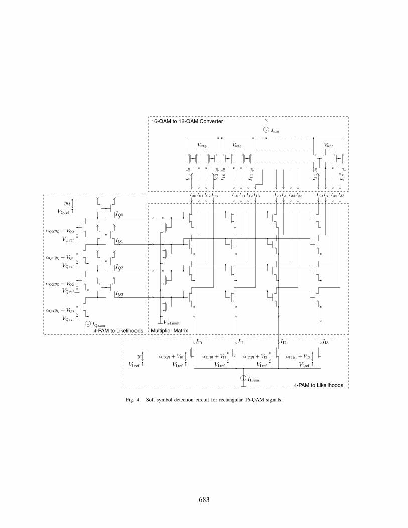
As an example, the circuit for detecting the soft symbols ofa 16-QAM signal (with the constellation given in Fig. 3) canbe obtained by the lower part of the circuit shown in Fig. 4.As mentioned before, it consists of three parts: two circuitscompute the soft symbols for a 4-PAM signal, extracted fromthe I-phase or the Q-phase of the QAM-signal, respectively.The matrix multiplier then computes all the symbol metricsout of the metrics from the two phases.
The soft symbols of a 12-QAM signal (with a cross-constellation, cf. Fig. 4) can be obtained by adding the top
681
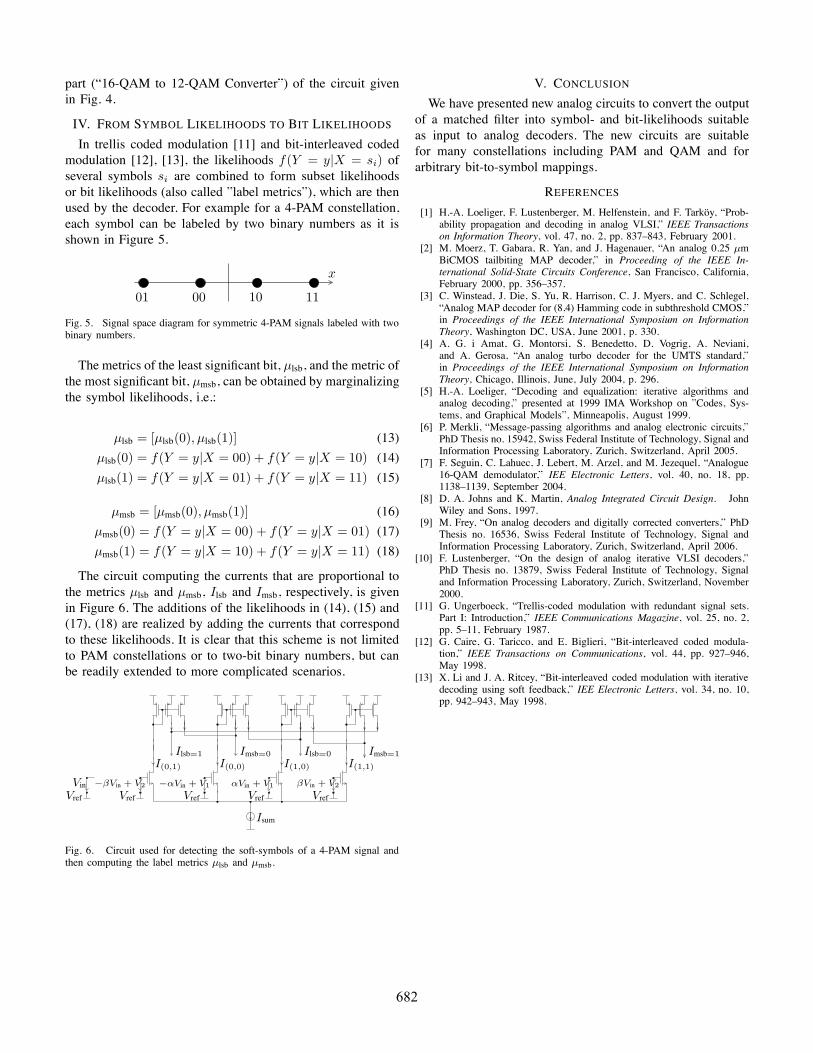
part (“16-QAM to 12-QAM Converter”) of the circuit givenin Fig. 4.
IV. FROM SYMBOL LIKELIHOODS TO BIT LIKELIHOODS
In trellis coded modulation [11] and bit-interleaved codedmodulation [12], [13], the likelihoods f(Y = y|X = si) ofseveral symbols si are combined to form subset likelihoodsor bit likelihoods (also called ”label metrics”), which are thenused by the decoder. For example for a 4-PAM constellation,each symbol can be labeled by two binary numbers as it isshown in Figure 5.
01 00 10 11
x
Fig. 5. Signal space diagram for symmetric 4-PAM signals labeled with twobinary numbers.
The metrics of the least significant bit, μlsb, and the metric ofthe most significant bit, μmsb, can be obtained by marginalizingthe symbol likelihoods, i.e.:
μlsb = [μlsb(0), μlsb(1)] (13)
μlsb(0) = f(Y = y|X = 00) + f(Y = y|X = 10) (14)
μlsb(1) = f(Y = y|X = 01) + f(Y = y|X = 11) (15)
μmsb = [μmsb(0), μmsb(1)] (16)
μmsb(0) = f(Y = y|X = 00) + f(Y = y|X = 01) (17)
μmsb(1) = f(Y = y|X = 10) + f(Y = y|X = 11) (18)
The circuit computing the currents that are proportional tothe metrics μlsb and μmsb, Ilsb and Imsb, respectively, is givenin Figure 6. The additions of the likelihoods in (14), (15) and(17), (18) are realized by adding the currents that correspondto these likelihoods. It is clear that this scheme is not limitedto PAM constellations or to two-bit binary numbers, but canbe readily extended to more complicated scenarios.
Isum
I(0,1) I(0,0) I(1,0) I(1,1)
Imsb=0 Imsb=1Ilsb=0Ilsb=1
Vin
Vref VrefVrefVrefVref
−βVin + V2 −αVin + V1 αVin + V1 βVin + V2
Fig. 6. Circuit used for detecting the soft-symbols of a 4-PAM signal andthen computing the label metrics µlsb and µmsb.
V. CONCLUSION
We have presented new analog circuits to convert the outputof a matched filter into symbol- and bit-likelihoods suitableas input to analog decoders. The new circuits are suitablefor many constellations including PAM and QAM and forarbitrary bit-to-symbol mappings.
REFERENCES
[1] H.-A. Loeliger, F. Lustenberger, M. Helfenstein, and F. Tarkoy, “Prob-ability propagation and decoding in analog VLSI,” IEEE Transactionson Information Theory, vol. 47, no. 2, pp. 837–843, February 2001.
[2] M. Moerz, T. Gabara, R. Yan, and J. Hagenauer, “An analog 0.25 µmBiCMOS tailbiting MAP decoder,” in Proceeding of the IEEE In-ternational Solid-State Circuits Conference, San Francisco, California,February 2000, pp. 356–357.
[3] C. Winstead, J. Die, S. Yu, R. Harrison, C. J. Myers, and C. Schlegel,“Analog MAP decoder for (8,4) Hamming code in subthreshold CMOS,”in Proceedings of the IEEE International Symposium on InformationTheory, Washington DC, USA, June 2001, p. 330.
[4] A. G. i Amat, G. Montorsi, S. Benedetto, D. Vogrig, A. Neviani,and A. Gerosa, “An analog turbo decoder for the UMTS standard,”in Proceedings of the IEEE International Symposium on InformationTheory, Chicago, Illinois, June, July 2004, p. 296.
[5] H.-A. Loeliger, “Decoding and equalization: iterative algorithms andanalog decoding,” presented at 1999 IMA Workshop on ”Codes, Sys-tems, and Graphical Models”, Minneapolis, August 1999.
[6] P. Merkli, “Message-passing algorithms and analog electronic circuits,”PhD Thesis no. 15942, Swiss Federal Institute of Technology, Signal andInformation Processing Laboratory, Zurich, Switzerland, April 2005.
[7] F. Seguin, C. Lahuec, J. Lebert, M. Arzel, and M. Jezequel, “Analogue16-QAM demodulator,” IEE Electronic Letters, vol. 40, no. 18, pp.1138–1139, September 2004.
[8] D. A. Johns and K. Martin, Analog Integrated Circuit Design. JohnWiley and Sons, 1997.
[9] M. Frey, “On analog decoders and digitally corrected converters,” PhDThesis no. 16536, Swiss Federal Institute of Technology, Signal andInformation Processing Laboratory, Zurich, Switzerland, April 2006.
[10] F. Lustenberger, “On the design of analog iterative VLSI decoders,”PhD Thesis no. 13879, Swiss Federal Institute of Technology, Signaland Information Processing Laboratory, Zurich, Switzerland, November2000.
[11] G. Ungerboeck, “Trellis-coded modulation with redundant signal sets.Part I: Introduction,” IEEE Communications Magazine, vol. 25, no. 2,pp. 5–11, February 1987.
[12] G. Caire, G. Taricco, and E. Biglieri, “Bit-interleaved coded modula-tion,” IEEE Transactions on Communications, vol. 44, pp. 927–946,May 1998.
[13] X. Li and J. A. Ritcey, “Bit-interleaved coded modulation with iterativedecoding using soft feedback,” IEE Electronic Letters, vol. 34, no. 10,pp. 942–943, May 1998.
682
VQ,ref
VQ,ref
VQ,ref
VQ,ref
VQ,ref
yQ
IQ,sum
αQ0yQ + VQ0
αQ1yQ + VQ1
αQ2yQ + VQ2
αQ3yQ + VQ3
IQ0
IQ1
IQ2
IQ3
4-PAM to Likelihoods
4-PAM to Likelihoods
II0 II1 II2 II3
II,sum
VI,refVI,ref VI,ref VI,ref VI,ref
yI αI0yI + VI0 αI1yI + VI1 αI2yI + VI2 αI3yI + VI3
Vref,mult
Multiplier Matrix
I00I01I02I03 I10I11I12I13 I20I21I22I23 I30I31I32I33
I 01
,out
I 02
,out
I 10
,out
I 11
,out
I 31
,out
I 32
,out
Vref,p Vref,p Vref,p
Isum
16-QAM to 12-QAM Converter
Fig. 4. Soft symbol detection circuit for rectangular 16-QAM signals.
683