Embed Size (px)
Citation preview
Analysis and implementation of a call simulator for Mobile@Home at Ericsson AB
Bachelor’s thesis performed at
Information Networks, Linköping Institute of Technology
By
Rasmus Larsson Edvard Wikström
LiTH-ISY-EX-ET-0268-2004
2004-06-04
Analysis and implementation of a call simulator for Mobile@Home at Ericsson AB
Examensarbete utfört i Informationsnät vid Linköpings tekniska högskola
av Rasmus Larsson
Edvard Wikström
LiTH-ISY-EX-ET-0268-2004
Handledare: Tomas Bornefall, Ericsson AB Examinator: Robert Forchheimer, ISY
Linköping 2004-06-04
Avdelning, Institution Division, Department
Institutionen för systemteknik 581 83 LINKÖPING
Datum Date 2004-06-04
Språk Language
Rapporttyp Report category
ISBN
Svenska/Swedish X Engelska/English
Licentiatavhandling X Examensarbete
ISRN LITH-ISY-EX-ET-0268-2004
C-uppsats D-uppsats
Serietitel och serienummer Title of series, numbering
ISSN
Övrig rapport ____
URL för elektronisk version http://www.ep.liu.se/exjobb/isy/2004/268/
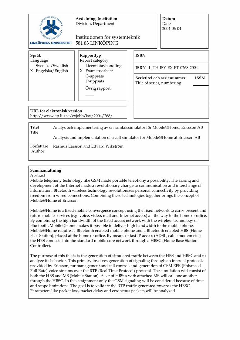
Titel Title
Analys och implementering av en samtalssimulator för Mobile@Home, Ericsson AB Analysis and implementation of a call simulator for Mobile@Home at Ericsson AB
Författare Author
Rasmus Larsson and Edvard Wikström
Sammanfattning Abstract Mobile telephony technology like GSM made portable telephony a possibility. The arising and development of the Internet made a revolutionary change to communication and interchange of information. Bluetooth wireless technology revolutionizes personal connectivity by providing freedom from wired connections. Combining these technologies together brings the concept of Mobile@Home of Ericsson. Mobile@Home is a fixed-mobile convergence concept using the fixed network to carry present and future mobile services (e.g. voice, video, mail and Internet access) all the way to the home or office. By combining the high bandwidth of the fixed access network with the wireless technology of Bluetooth, Mobile@Home makes it possible to deliver high bandwidth to the mobile phone. Mobile@Home requires a Bluetooth enabled mobile phone and a Bluetooth enabled HBS (Home Base Station), placed at the home or office. By means of fast IP access (ADSL, cable modem etc.) the HBS connects into the standard mobile core network through a HBSC (Home Base Station Controller). The purpose of this thesis is the generation of simulated traffic between the HBS and HBSC and to analyze its behavior. This primary involves generation of signaling through an internal protocol, provided by Ericsson, for management and call control, and generation of GSM EFR (Enhanced Full Rate) voice streams over the RTP (Real Time Protocol) protocol. The simulation will consist of both the HBS and MS (Mobile Station). A set of HBS: s with attached MS will call one another through the HBSC. In this assignment only the GSM signaling will be considered because of time and scope limitations. The goal is to validate the RTP traffic generated towards the HBSC. Parameters like packet loss, packet delay and erroneous packets will be analyzed.

Nyckelord Keyword Ericsson AB, Mobile@Home, GSM, Bluetooth, VoIP, TCP/IP, HMAP, RTP, EFR, G.711, Linux
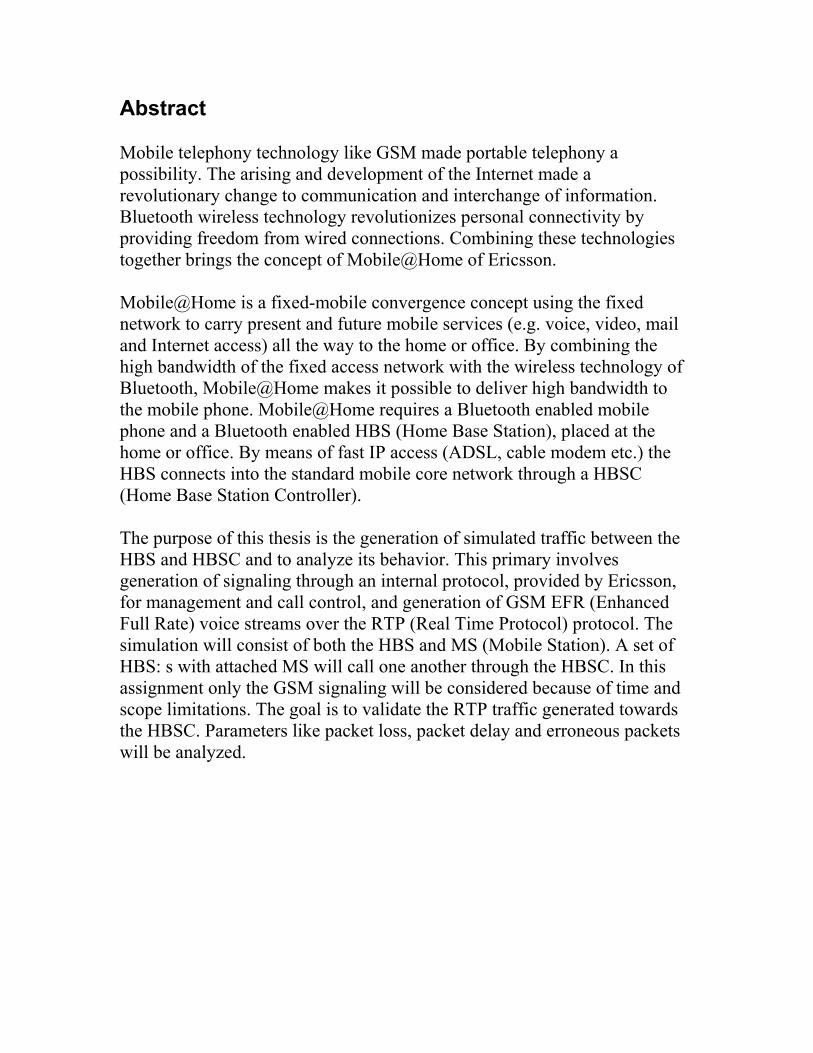
Abstract Mobile telephony technology like GSM made portable telephony a possibility. The arising and development of the Internet made a revolutionary change to communication and interchange of information. Bluetooth wireless technology revolutionizes personal connectivity by providing freedom from wired connections. Combining these technologies together brings the concept of Mobile@Home of Ericsson. Mobile@Home is a fixed-mobile convergence concept using the fixed network to carry present and future mobile services (e.g. voice, video, mail and Internet access) all the way to the home or office. By combining the high bandwidth of the fixed access network with the wireless technology of Bluetooth, Mobile@Home makes it possible to deliver high bandwidth to the mobile phone. Mobile@Home requires a Bluetooth enabled mobile phone and a Bluetooth enabled HBS (Home Base Station), placed at the home or office. By means of fast IP access (ADSL, cable modem etc.) the HBS connects into the standard mobile core network through a HBSC (Home Base Station Controller). The purpose of this thesis is the generation of simulated traffic between the HBS and HBSC and to analyze its behavior. This primary involves generation of signaling through an internal protocol, provided by Ericsson, for management and call control, and generation of GSM EFR (Enhanced Full Rate) voice streams over the RTP (Real Time Protocol) protocol. The simulation will consist of both the HBS and MS (Mobile Station). A set of HBS: s with attached MS will call one another through the HBSC. In this assignment only the GSM signaling will be considered because of time and scope limitations. The goal is to validate the RTP traffic generated towards the HBSC. Parameters like packet loss, packet delay and erroneous packets will be analyzed.
1 INTRODUCTION ................................................................................................................ 1 1.1 THE ASSIGNMENT................................................................................................................................. 2 1.2 OUTLINE OF THE THESIS ....................................................................................................................... 3
2 BACKGROUND .................................................................................................................... 4 2.1 MOBILE@HOME................................................................................................................................... 4
2.1.1 Architecture.................................................................................................................................. 4 2.2 HMAP.................................................................................................................................................. 5 2.3 GSM .................................................................................................................................................... 6 2.4 G.711 ................................................................................................................................................... 7 2.5 EFR...................................................................................................................................................... 8 2.6 BLUETOOTH.......................................................................................................................................... 8 2.7 ISO/OSI NETWORK MODEL ................................................................................................................. 9 2.8 IP........................................................................................................................................................ 12 2.9 UDP ................................................................................................................................................... 13 2.10 TCP.................................................................................................................................................. 14 2.11 VOIP ................................................................................................................................................ 16 2.12 RTP.................................................................................................................................................. 16 2.13 RTCP ............................................................................................................................................... 18
3 METHOD.................................................................................................................................... 19 3.1 APPROACH.......................................................................................................................................... 19 3.2 GOAL.................................................................................................................................................. 20 3.3 SCOPE AND LIMITATIONS.................................................................................................................... 20
4 MOBILE@HOME COMPONENT ANALYSIS................................ 21 4.1 HBSC................................................................................................................................................. 21 4.2 HBS ................................................................................................................................................... 22 4.3 MS ..................................................................................................................................................... 23
5 SIGNALING ANALYSIS........................................................................................... 24 5.1 THE Y-INTERFACE .............................................................................................................................. 24
5.1.1 TCP-CONF ................................................................................................................................ 25 5.1.2 TCP-ADM .................................................................................................................................. 26 5.1.3 TCP-L3....................................................................................................................................... 26 5.1.4 Distinction of messages.............................................................................................................. 26
5.2 HBS CONNECTIONS ............................................................................................................................ 27 5.2.1 HBS attachment ......................................................................................................................... 28
5.3 MS ATTACHMENT .............................................................................................................................. 28 5.3.1 Originating Call......................................................................................................................... 29 5.3.2 Terminating Call ........................................................................................................................ 32
6 DESIGN......................................................................................................................................... 35 6.1 PROGRAM DESIGN............................................................................................................................... 35 6.2 SIMULATOR FUNCTIONALITY.............................................................................................................. 37
7 IMPLEMENTATION .................................................................................................... 39 7.1 RTP LIBRARY..................................................................................................................................... 39
7.1.1 Payload ...................................................................................................................................... 40
7.2 SIMULATOR MODULES: ....................................................................................................................... 40 7.2.1 hbs-ms-sim.c............................................................................................................................... 41 7.2.2 sched.h/.c ................................................................................................................................... 42 7.2.3 putils.h/c..................................................................................................................................... 42 7.2.4 connection.h/.c ........................................................................................................................... 42 7.2.5 hbs.h/c ........................................................................................................................................ 43 7.2.6 ms.h/c ......................................................................................................................................... 43 7.2.7 hmap.h/c..................................................................................................................................... 43 7.2.8 print.h./c..................................................................................................................................... 43 7.2.9 utils.h/c....................................................................................................................................... 44 7.2.10 fileparser.h/c ............................................................................................................................ 44 7.2.11 rtpsend.h/c................................................................................................................................ 44 7.2.12 a3a8.c....................................................................................................................................... 44 7.2.13 hbsmssim.conf .......................................................................................................................... 44
7.3 CONFIGURATION OPTIONS.................................................................................................................. 45
8 ANALYSIS OF THE IMPLEMENTATION ......................................... 48 8.1 USABILITY.......................................................................................................................................... 48 8.2 RELIABILITY....................................................................................................................................... 51 8.3 PERFORMANCE ................................................................................................................................... 52 8.4 SCALABILITY...................................................................................................................................... 52 8.5 MEMORY MANAGEMENT .................................................................................................................... 53 8.6 SECURITY ........................................................................................................................................... 53 8.7 CONCLUSIONS AND PROBLEMS ........................................................................................................... 53 8.8 FUTURE WORK ................................................................................................................................... 54
8.8.1 Authentication ............................................................................................................................ 55
9 REFERENCES ...................................................................................................................... 56 APPENDIX A: THE README FILE...................................................................................................... 60 APPENDIX B: THE CONFIGURATION FILE FOR THE SIMULATOR......................................... 67
Abbreviations ACELP Algebraic Code Excited Linear Prediction ACL Asynchronous Connectionless ADSL Asymmetrical Digital Subscriber Line ATM Asynchronous Transfer Mode ASN.1 Abstract Syntax Notation One AUC Authentication Center BCD Binary Code Digit BGRR Bluetooth GPRS Radio Resource BSC Base Station Controller BTS Base Transceiver Station CGI Cell Global Identity CI Cell Identity DHCP Dynamic Host Configuration Protocol DTAP Direct Application Part EDGE Enhanced Data rates for GSM Evolution EFR Enhanced Full Rate EM Element Manager ER Edge Router ETSI European Telecommunications Standards Institute IEEE Institute of Electrical and Electronics Engineers IETF Internet Engineering Task Force IRDA Infrared Data Association GMSC Gateway MSC GSM Global System for Mobile Communication GPRS Global Packet Radio Service HBS Home Base Station HBSC Home Base Station Controller HDML Handheld Device Markup Language HLR Home Location Register HMAP Home Mobile Application Part
IMSI International Mobile Subscriber Identity IP Internet Protocol IPsec IP Security IPT IP Telephony ISP Internet Service Provider LAI Location Area Identification LAN Local Area Network MAP Mobile Application Part MAC Media Access Control MS Mobile Station (mobile phone) MSC Mobile Services Switching Center MSISDN Mobile Station ISDN MSP Mobile Services Profile NAT Network Address Translation NT Network Terminator NSS Network Switching Subsystem OSI Open System Interconnection PLMN Public Land Mobile Network PSTN Public Switched Telephone Network QoS Quality of Service RBS Radio Base Station RNC Radio Network Controller SCN Switched Circuit Network SCO Synchronous Connection Oriented SGSN Signaling GPRS Support Node SS7 Signaling System No. 7 STOC Signaling Terminal For Open Communication TCP Transmission Control Protocol TSMP True Symmetric Multi Processor UDP User Datagram Protocol
VG Voice Gateway VLR Visitor Location Register VoIP Voice over IP WPAN Wireless Personal Area Network 3GSM Third Generation GSM
Analysis and implementation of a call simulator for Mobile@Home at Ericsson AB
1 Introduction The mobile phone is becoming an essential part of our life and the growth in traffic and services like SMS and MMS is substantial. Users relish the convenience and availability of the “being always-on” feeling. Carrying their personal communication device wherever they go. Mobile@Home [1] wants to create the best possible connectivity to those places where users spend most of their time: the home and the office environment. Mobile@Home is a solution building on Ericsson’s strength in both fixed and wireless networks as well as core mobile phone technology. Mobile@Home allows the delivery of services from the mobile service network (voice, voicemail, SMS, MMS, WAP, GPRS, location lased services, online gaming etc.) over the fixed backbone and access networks. The idea of Mobile@Home is to deliver the same services from the core network but utilize a different access method. As fixed IP access networks already existed long before mobile networks, the goal is to reuse these networks. One initial problem was to connect the mobile phone in some way to the mobile core network without using the mobile access network. The solution is to make use of Bluetooth on one side, in the mobile phone, and establish some sort of connection between an access point and the mobile network on the other side. Furthermore, the challenge is to provide a way of delivering voice calls and mobile services at lower costs for the operator than when using the mobile network. Naturally, this would also be an advantage for the end user. Mobile@Home offers the mobile operator a new way to deliver transparent GSM/GPRS and upcoming 3G services to users in homes and offices at an attractive tariff, thereby increasing traffic volume and revenue. The same service is delivered as over the GSM interface, giving the operators the possibility to offload their expensive radio networks. To broadband operators this is a new application besides Internet to utilize ADSL, cable networks and other fast access methods. This also provides new revenue to the operator.
Chapter 1 - Introduction 1
Analysis and implementation of a call simulator for Mobile@Home at Ericsson AB
To end users, this offers high quality mobile services in the home and the office. One small HBS with Bluetooth offer services for multiple users, 3 simultaneous calls and several data sessions.
1.1 The Assignment Ericsson has at the moment a working prototype of the Mobile@Home solution. There are customized ready to use mobile phones and HBS modules. An operational HBSC is placed in Stockholm, Sweden, the only one available at the moment. Though, one will be placed later on at Linköping. The equipment is used for testing purposes, further development and for demonstrations to potential costumers. As mentioned, there is ongoing development regarding all components, improving and fine-tuning for better performance. Testing the prototype is a vital process to reproduce the correct and expected behavior of the system, correcting faults and making the proper adjustments as necessary. The purpose of our assignment is to generate the traffic between the HBS and HBSC. This will be done by simulating a set of HBS: s and attached MS and let them call one another through the HBSC. To achieve this, a combination of standardized communication protocols, IP/TCP/UDP/RTP, for signaling and voice streams will be used. A proprietary protocol of Ericsson is used for signaling on top of TCP. This will be implemented using the Linux platform following the POSIX [2] standard, making it easier to port the code to other environments if necessary. Finally, this will end with an analysis of the traffic behavior regarding a set of specified parameters. This primary involves packet delay, packet loss and erroneous packets. These parameters will affect the voice quality of an ongoing call, our analysis and observations will hopefully provide sufficient data to identify the most important or significant causes of distortion. In addition to the study and results, suggestions to improve the implementation will be provided.
2 Chapter 1 - Introduction
Analysis and implementation of a call simulator for Mobile@Home at Ericsson AB
1.2 Outline of the Thesis Chapter 2 contains the technologies and background material related to our assignment. Chapter 3 presents our method and analysis to approach a solution. Chapter 4 presents the Mobile@Home components. Chapter 5 explains the signaling analysis. Chapter 6 explains the program design. Chapter 7 presents the implementation. Chapter 8 presents the analysis of the implementation.
Chapter 1 - Introduction 3
Analysis and implementation of a call simulator for Mobile@Home at Ericsson AB
2 Background
2.1 Mobile@Home The concept of Mobile@Home [3] aims at creating a new radio access method for GSM services. Technologies used are based on unlicensed Bluetooth radio and the IP network layer protocol. Mobile@Home provides high bandwidth and seamless service available both at the office and at home, giving the personal phone one number to be used everywhere. This provides convenience by making all services available no matter location.
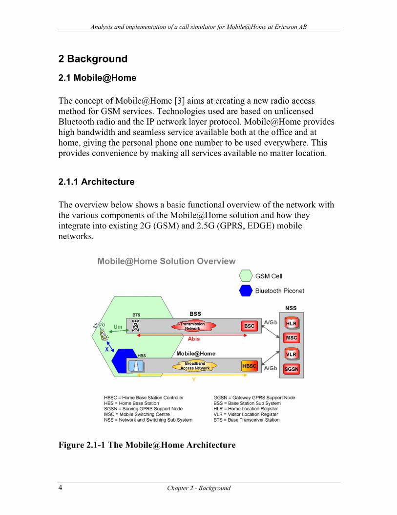
2.1.1 Architecture The overview below shows a basic functional overview of the network with the various components of the Mobile@Home solution and how they integrate into existing 2G (GSM) and 2.5G (GPRS, EDGE) mobile networks.
Figure 2.1-1 The Mobile@Home Architecture
4 Chapter 2 - Background
Analysis and implementation of a call simulator for Mobile@Home at Ericsson AB
The Mobile@Home solution basically requires three parts. Mobile phone with Bluetooth: The user will need a mobile phone with Bluetooth. Mobile@Home uses a specified protocol called MSP to establish signaling and communication between the mobile phone with Bluetooth and the HBS. TMSP-support for Ericsson´s R520 and T68 mobile phones are implemented. Future Bluetooth enabled mobile phones will also work with Mobile@Home. Eventually, any brand of mobile phone with Bluetooth will be supported. Home Base Station (HBS): This is a small Bluetooth "access point" to be installed in the home or office, connected through standard Ethernet cable to the broadband access NT. The HBS is about the size of a modem and is responsible of controlling the mobile phones attached to it. Home Base Station Controller (HBSC): The HBSC is comparable to the BSC of 2G (GSM) and 2.5G (GPRS) networks or RNC of 3G (UMTS) mobile networks in terms of functionality. The HBSC uses standard Ericsson AXE platform and is fully compatible with other network components. The connection between the HBS and HBSC is based on IP. For the services to work with acceptable quality the system requires that the IP connection is a broadband access.
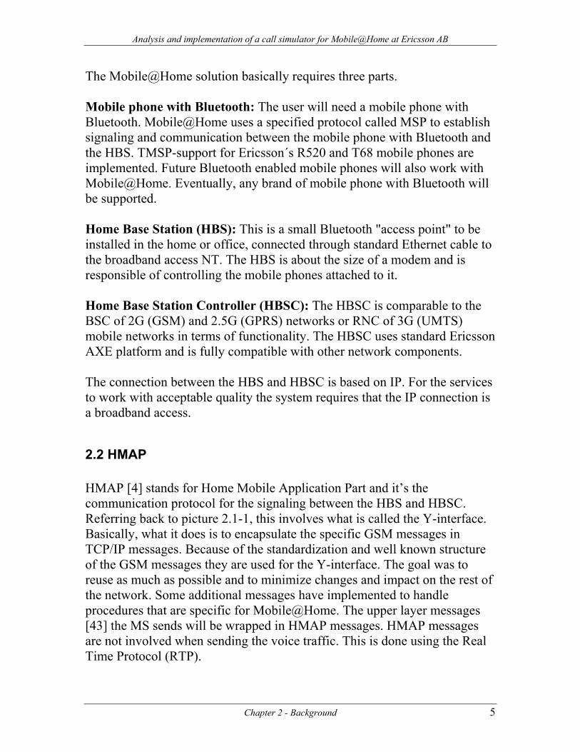
2.2 HMAP HMAP [4] stands for Home Mobile Application Part and it’s the communication protocol for the signaling between the HBS and HBSC. Referring back to picture 2.1-1, this involves what is called the Y-interface. Basically, what it does is to encapsulate the specific GSM messages in TCP/IP messages. Because of the standardization and well known structure of the GSM messages they are used for the Y-interface. The goal was to reuse as much as possible and to minimize changes and impact on the rest of the network. Some additional messages have implemented to handle procedures that are specific for Mobile@Home. The upper layer messages [43] the MS sends will be wrapped in HMAP messages. HMAP messages are not involved when sending the voice traffic. This is done using the Real Time Protocol (RTP).
Chapter 2 - Background 5
Analysis and implementation of a call simulator for Mobile@Home at Ericsson AB
Figure 2.2-1 HMAP Protocol
2.3 GSM GSM [5] is an open, non-proprietary wireless technology that allows delivery of high quality digital voice services, and ‘always-on’ data services. GSM is made up of a family of platforms. These platforms include GPRS, EDGE and 3GSM. With these three different platforms service providers can provide customers with innovative voice and data technologies. One of its great strengths is the international roaming capability. This gives users seamless and standardized contact ability in more than 170 countries. GSM satellite roaming has extended service access to areas where terrestrial coverage is not available. The combination of these platforms has given services like SMS, MMS, WAP and HDML a new meaning of communication and accessibility to information. 2.3.1 IMSI The IMSI [6] [7] number identifies an MS towards the network. Foreign networks also use this number to locate the correct HLR whenever a MS is a visitor. This does not equal the dialing number of the MS, which is the MSISDN, and is mapped to the IMSI number in the HLR. The IMSI number consists of: IMSI = MCC + MNC + MSIN MCC = Mobile Country Code MNC = Mobile Network Code MSIN = Mobile Subscriber Identification Number
6 Chapter 2 - Background
Analysis and implementation of a call simulator for Mobile@Home at Ericsson AB
2.3.2 IMEI IMEI [6] [8] stands for International Mobile Equipment Identity and is a unique identifier consisting of a 15-digit number assigned to all GSM devices. This number is sent whenever the network asks for it. The IMEI is like a serial number and is used by the network to identify the handset. An operator might request the IMEI to determine if a device is in disrepair, stolen or to gather statistics on fraud or faults. 2.3.3 Authentication To prevent unauthorized access to the network, every MS needs to authenticate [7] itself. At subscription time, each subscriber is assigned a subscriber authentication Key (Ki). This key is stored in the users SIM-card along with the A3 algorithm, which is used to generate a response to the network. This key is also known by the operator in the AUC along with the users IMSI number. During specific moments the network will send a non-predictable random number, RAND, to the MS. The MS will with the RAND number and help of the A3 algorithm generate a signed response value, called SRES. This new created value will be sent back to the network for verification. If the value is correct the MS is successfully authenticated and can proceed for further services.
2.4 G.711 G.711 [9] is an ITU-T standard for encoding telephone audio on a 64 kbps channel. It provides a compression/decompression algorithm to deliver transmission of encoded speech signals sampled at the rate of 8 kHz. The G.711 standard uses pulse code modulation (PCM) when processing the analog speech, which can then be transmitted and received as binary data. There are two variants of this codec: µ-law which compresses frames of 14-bit linear PCM samples into frames of 8-bit logarithmic PCM code words. A-law which compresses 13-bit linear PCM samples into 8-bit logarithmic PCM code words. A-law is the one used in Europe.
Chapter 2 - Background 7
Analysis and implementation of a call simulator for Mobile@Home at Ericsson AB
2.5 EFR The EFR (Enhanced Full Rate)[10] voice codec is a coding algorithm that facilitates the conversion of analog speech into a digital data stream that can be modulated for transmission over the radio channel, the GSM mobile phone network. It has been standardized by ETSI. During a voice transmission a signal from a microphone is digitized, converted into a string of ones and zeros, in a special chip. The digitized voice is then transferred in a mobile network. A reverse process applies at the other end and the digitized signal is converted into voice. The speech is sampled at 8 kHz and segmented into 20 ms frames (160 samples) and it has a bit rate of 12.2 kbps. It is based on the principle of linear-predictive analysis-by-synthesis coding also known as ACELP (Algebraic Code Excited Linear Prediction). Tests have demonstrated that the voice quality of the EFR codec compares favorably to that of a landline telephone and provides voice quality that is better than most mobile communications technologies. The EFR technology has to be supported both by the terminal and the operator network.
2.6 Bluetooth Bluetooth [11] enables a WPAN that connect devices in close proximity or short-range radio devices. WPAN is being standardized by the IEEE 805.15 working group and is largely based in the Bluetooth Special Interest Group specifications. Bluetooth encompasses both a standard communications interface and a low-cost computer chip. Ericsson conceived Bluetooth as a technology in 1994 and in 1998 Nokia, Ericsson, IBM, Intel and Toshiba founded the Bluetooth SIG trade association. Bluetooth operates in the globally available 2.45 GHz ISM 'free band' and provides low-cost, low power, robust, secure, efficient, high capacity, ad hoc voice and data networking of up to 1 Mb/sec, in a range of 10 meters. The maximum achievable speed is 723.2 kbps dynamically downstream/upstream. Unlike IRDA it does not require line of sight, allowing devices to communicate with each other from pockets, bags and around corners.
8 Chapter 2 - Background
Analysis and implementation of a call simulator for Mobile@Home at Ericsson AB
The piconet is the basic part of the Bluetooth wireless technology. A piconet contains one master, up to 7 active slaves and 255 parked slaves. All communication in the piconet is synchronized and controlled by the master, and is only possible between the master and a slave at once. 2.6.1 SCO The SCO [11] [12] link is a symmetric, point-to-point link between the master and a single slave in the piconet. The SCO link involves reservation of slots and can therefore be considered as a circuit-switched connection between the master and the slave. The master maintains the link by using reserved timeslots at regular intervals. The SCO link is typically used to support time-bounded information like voice. The master can support up to three SCO links to the same slave or to different slaves. Raw data can be sent over SCO, and data rates may also be negotiated, thus improving on the current data rates for high QoS connections. With this function, detection and re-transmission of lost or destroyed voice packets is possible with a minimum impact on real-time performance, essential for high quality voice transmission. Voice channels are SCO links and transmit at a data rate of 64 kbps. 2.6.2 ACL The ACL [11] [12] link provides a packet-switched connection between the master and all active slaves in the piconet. A slave can send an ACL packet if it has been addressed by the master in the previous slot. To ensure data integrity, ACL packets are retransmitted. Only a single ACL link can exist between a master and a slave. The master schedules ACL packets in the slots not reserved for the SCO links. The specifications define 7 kinds of ACL packets, three DM (data-medium rate) packets, three DH (data-high rate) packets and one AUX packet.
2.7 ISO/OSI Network Model Standards are extremely important in the field of networking. The whole purpose of a network is to allow different computers to communicate. If the computers do not follow a common standard, they will not be able to communicate.
Chapter 2 - Background 9
Analysis and implementation of a call simulator for Mobile@Home at Ericsson AB
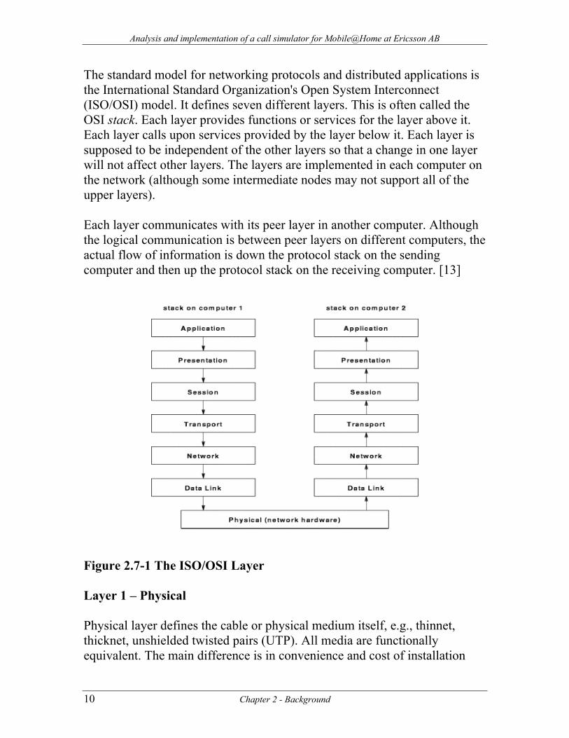
The standard model for networking protocols and distributed applications is the International Standard Organization's Open System Interconnect (ISO/OSI) model. It defines seven different layers. This is often called the OSI stack. Each layer provides functions or services for the layer above it. Each layer calls upon services provided by the layer below it. Each layer is supposed to be independent of the other layers so that a change in one layer will not affect other layers. The layers are implemented in each computer on the network (although some intermediate nodes may not support all of the upper layers). Each layer communicates with its peer layer in another computer. Although the logical communication is between peer layers on different computers, the actual flow of information is down the protocol stack on the sending computer and then up the protocol stack on the receiving computer. [13]
Figure 2.7-1 The ISO/OSI Layer Layer 1 – Physical Physical layer defines the cable or physical medium itself, e.g., thinnet, thicknet, unshielded twisted pairs (UTP). All media are functionally equivalent. The main difference is in convenience and cost of installation
10 Chapter 2 - Background
Analysis and implementation of a call simulator for Mobile@Home at Ericsson AB
and maintenance. Converters from one media to another operate at this level. This is the only layer that actually send bits. Layer 2 - Data Link Data Link layer defines the format of data on the network. A network data frame, a packet, includes checksum, source and destination address, and data. The data link layer handles the physical and logical connections to the packet's destination, using a network interface, i.e. Ethernet or Token Ring. It also detects and corrects any errors on the link, and also provides flow control. Layer 3 – Network Finds a route for packets to take through the network. Directs packets to the correct computer. IP belongs to this layer. Layer 4 – Transport Transport layer subdivides user-buffer into network-buffer sized datagrams and enforces desired transmission control. Two transport protocols, Transmission Control Protocol (TCP) and User Datagram Protocol (UDP), belong to this layer. Layer 5 – Session The session protocol defines the format of the data sent over the connections. Layer 6 – Presentation External Data Representation (XDR) sits at the presentation level. It converts local representation of data to its canonical form and vice versa. The canonical uses a standard byte ordering and structure packing convention, independent of the host. Layer 7 – Application Provides network services to the end-users. Mail, ftp, telnet, DNS, NIS, NFS are examples of network applications.
Chapter 2 - Background 11
Analysis and implementation of a call simulator for Mobile@Home at Ericsson AB
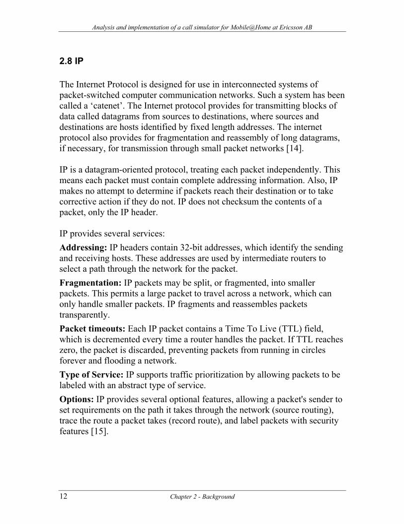
2.8 IP The Internet Protocol is designed for use in interconnected systems of packet-switched computer communication networks. Such a system has been called a ‘catenet’. The Internet protocol provides for transmitting blocks of data called datagrams from sources to destinations, where sources and destinations are hosts identified by fixed length addresses. The internet protocol also provides for fragmentation and reassembly of long datagrams, if necessary, for transmission through small packet networks [14]. IP is a datagram-oriented protocol, treating each packet independently. This means each packet must contain complete addressing information. Also, IP makes no attempt to determine if packets reach their destination or to take corrective action if they do not. IP does not checksum the contents of a packet, only the IP header. IP provides several services: Addressing: IP headers contain 32-bit addresses, which identify the sending and receiving hosts. These addresses are used by intermediate routers to select a path through the network for the packet. Fragmentation: IP packets may be split, or fragmented, into smaller packets. This permits a large packet to travel across a network, which can only handle smaller packets. IP fragments and reassembles packets transparently. Packet timeouts: Each IP packet contains a Time To Live (TTL) field, which is decremented every time a router handles the packet. If TTL reaches zero, the packet is discarded, preventing packets from running in circles forever and flooding a network. Type of Service: IP supports traffic prioritization by allowing packets to be labeled with an abstract type of service. Options: IP provides several optional features, allowing a packet's sender to set requirements on the path it takes through the network (source routing), trace the route a packet takes (record route), and label packets with security features [15].
12 Chapter 2 - Background
Analysis and implementation of a call simulator for Mobile@Home at Ericsson AB
Figure 2.8-1IP Header
2.9 UDP This protocol provides a procedure for application programs to send messages to other programs with a minimum of protocol mechanism. The protocol is transaction oriented, and delivery and duplicate protection are not guaranteed. Applications requiring ordered reliable delivery of streams of data should use the Transmission Control Protocol (TCP) [16].
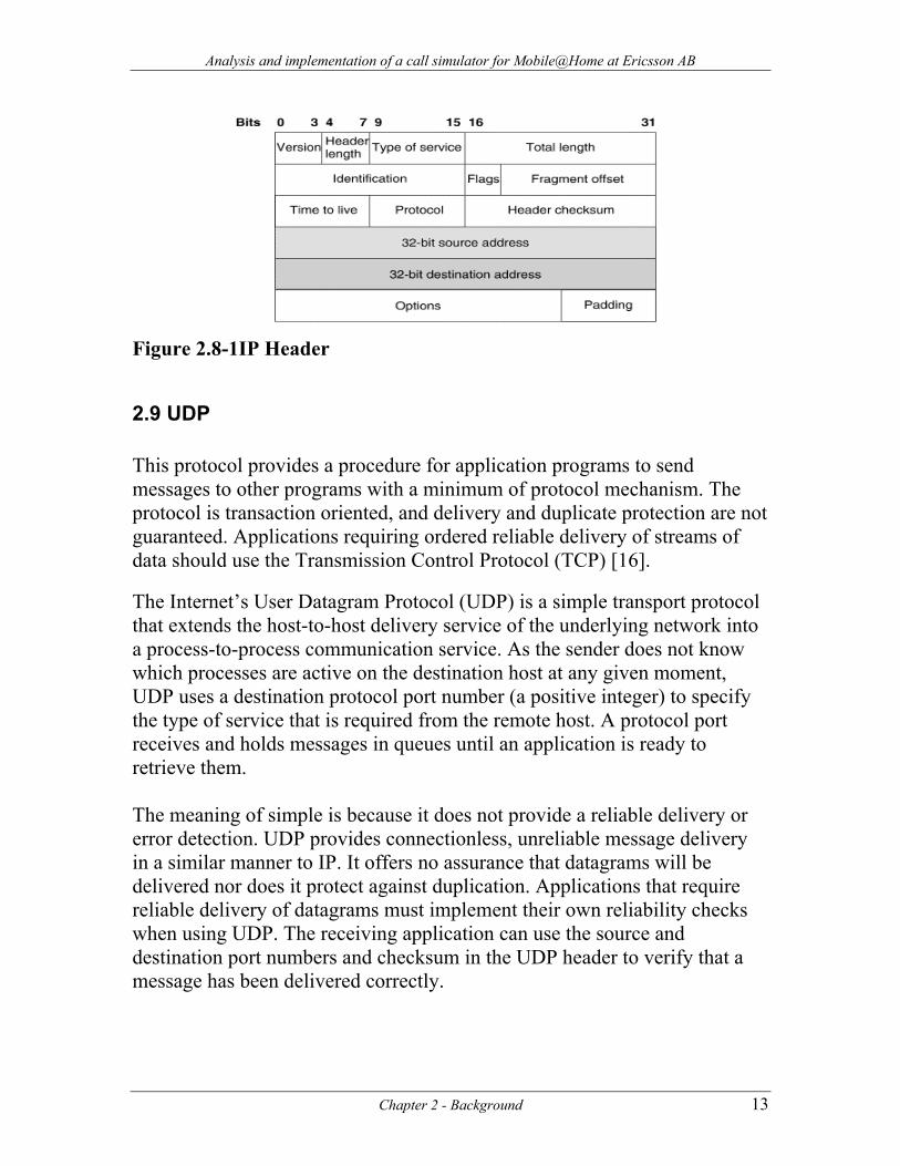
The Internet’s User Datagram Protocol (UDP) is a simple transport protocol that extends the host-to-host delivery service of the underlying network into a process-to-process communication service. As the sender does not know which processes are active on the destination host at any given moment, UDP uses a destination protocol port number (a positive integer) to specify the type of service that is required from the remote host. A protocol port receives and holds messages in queues until an application is ready to retrieve them. The meaning of simple is because it does not provide a reliable delivery or error detection. UDP provides connectionless, unreliable message delivery in a similar manner to IP. It offers no assurance that datagrams will be delivered nor does it protect against duplication. Applications that require reliable delivery of datagrams must implement their own reliability checks when using UDP. The receiving application can use the source and destination port numbers and checksum in the UDP header to verify that a message has been delivered correctly.
Chapter 2 - Background 13
Analysis and implementation of a call simulator for Mobile@Home at Ericsson AB
Figure 2.9-1 UDP Header
2.10 TCP The Transmission Control Protocol (TCP) is intended for use as a highly reliable host-to-host protocol between hosts in packet-switched computer communication networks, and in interconnected systems of such networks [17]. TCP provides a connection oriented, reliable, byte stream service. The term connection-oriented means the two applications using TCP must establish a TCP connection with each other before they can exchange data [18]. It is a full duplex protocol, meaning that each TCP connection supports a pair of byte streams, one flowing in each direction. TCP includes a flow-control mechanism for each of these byte streams that allow the receiver to limit how much data the sender can transmit. TCP also implements a congestion-control mechanism. TCP provides the following services: Stream Data Transfer From the application's viewpoint, TCP transfers a contiguous stream of bytes. TCP does this by grouping the bytes in TCP segments, which are passed to IP for transmission to the destination. TCP itself decides how to segment the data and it may forward the data at its own convenience. Reliability TCP assigns a sequence number to each byte transmitted, and expects a positive acknowledgment (ACK) from the receiving TCP. If the ACK is not received within a timeout interval, the data is retransmitted. The receiving
14 Chapter 2 - Background
Analysis and implementation of a call simulator for Mobile@Home at Ericsson AB
TCP uses the sequence numbers to rearrange the segments when they arrive out of order, and to eliminate duplicate segments. Flow Control The receiving TCP, when sending an ACK back to the sender, also indicates to the sender the number of bytes it can receive beyond the last received TCP segment, without causing overrun and overflow in its internal buffers. This is sent in the ACK in the form of the highest sequence number it can receive without problems. Multiplexing To allow for many processes within a single host to use TCP communication facilities simultaneously, the TCP provides a set of addresses or ports within each host. Concatenated with the network and host addresses from the internet communication layer, this forms a socket. A pair of sockets uniquely identifies each connection. Logical Connections The reliability and flow control mechanisms described above require that TCP initializes and maintains certain status information for each data stream. The combination of this status, including sockets, sequence numbers and window sizes, is called a logical connection. The pair of sockets used by the sending and receiving processes uniquely identifies each connection. Full Duplex TCP provides for concurrent data streams in both directions.
Chapter 2 - Background 15
Analysis and implementation of a call simulator for Mobile@Home at Ericsson AB
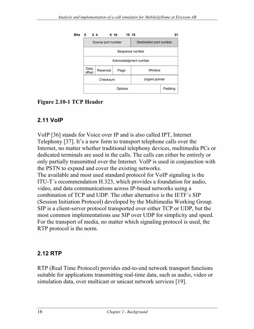
Figure 2.10-1 TCP Header
2.11 VoIP VoIP [36] stands for Voice over IP and is also called IPT, Internet Telephony [37]. It’s a new form to transport telephone calls over the Internet, no matter whether traditional telephony devices, multimedia PCs or dedicated terminals are used in the calls. The calls can either be entirely or only partially transmitted over the Internet. VoIP is used in conjunction with the PSTN to expand and cover the existing networks. The available and most used standard protocol for VoIP signaling is the ITU-T´s recommendation H.323, which provides a foundation for audio, video, and data communications across IP-based networks using a combination of TCP and UDP. The other alternative is the IETF´s SIP (Session Initiation Protocol) developed by the Multimedia Working Group. SIP is a client-server protocol transported over either TCP or UDP, but the most common implementations use SIP over UDP for simplicity and speed. For the transport of media, no matter which signaling protocol is used, the RTP protocol is the norm.
2.12 RTP RTP (Real Time Protocol) provides end-to-end network transport functions suitable for applications transmitting real-time data, such as audio, video or simulation data, over multicast or unicast network services [19].
16 Chapter 2 - Background
Analysis and implementation of a call simulator for Mobile@Home at Ericsson AB
RTP provides end-to-end delivery services for data with real-time characteristics, such as interactive audio and video. Those services include payload type identification, sequence numbering, time stamping and delivery monitoring. Applications typically run RTP on top of UDP to make use of its multiplexing and checksum services; both protocols contribute parts of the transport protocol functionality. RTP supports data transfer to multiple destinations using multicast distribution if provided by the underlying network. Note that RTP itself does not provide any mechanism to ensure timely delivery or provide other quality-of-service guarantees, but relies on lower-layer services to do so. It does not guarantee delivery or prevent out-of-order delivery, nor does it assume that the underlying network is reliable and delivers packets in sequence. The sequence numbers included in RTP allow the receiver to reconstruct the sender's packet sequence, but sequence numbers might also be used to determine the proper location of a packet, for example in video decoding, without necessarily decoding packets in sequence. While RTP is primarily designed to satisfy the needs of multiparticipant multimedia conferences, it is not limited to that particular application. Storage of continuous data, interactive distributed simulation, active badge, and control and measurement applications may also find RTP applicable. The services provided by RTP are the following: Payload type identification: Lets applications using the protocol know which kind of information is being transmitted (audio, video, etc). Sequencing: When RTP runs on top of a datagram-based service, packet sequence numbers are required to reassemble the information stream in the destination (packets may not arrive in the correct order because each one can take an independent route from source to destination). Time stamping: In applications such as teleconference, timestamps must be provided in the packets to assure synchronization of the devices participating in the conference; otherwise, information might be lost. This time stamping is also important in control and monitoring applications, for having an accurate recording of the monitored events [20].
Chapter 2 - Background 17
Analysis and implementation of a call simulator for Mobile@Home at Ericsson AB
2.13 RTCP RTP control protocol (RTCP) is used to monitor the quality of service and to convey information about the participants in an on-going session.
Delivery monitoring allows the participating applications to collect and share statistics about the performance of the data transport service. RTCP gives useful information that may be distributed among the participants in a communication group, e.g., the names and locations of the parties, when and why a party is leaving, etc. [20].
18 Chapter 2 - Background
Analysis and implementation of a call simulator for Mobile@Home at Ericsson AB
3 Method
3.1 Approach As stated earlier, our assignment is to develop an application that can simulate the functionality of the HBS and the MS to generate valid traffic against the HBSC. The purpose is to analyze how the traffic behaves and what factors can be of importance regarding the RTP traffic. In order to accomplish this, it involves at first hand the study of the required signaling to attach an HBS towards the HBSC, the process of registering an MS towards the HBS and HBSC, the establishment and connection of a call and finally the termination of the call. Further studies are needed regarding identification and authentication of both HBS and MS. The system specification of Mobile@Home that we will follow is 1.2 [42] To start with, there is a HBS and HBSC simulator that can be used in an early stage to get a feel of the functionality and behavior of the Mobile@Home solution. We have at our disposal a working set of the equipment, a HBS and MS, which will be used to determine and analyze the signaling and RTP traffic. This equipment will be connected to a HBSC placed in Kista, Stockholm. After discussion with responsible people involved in this project at Ericsson, we decided to write the software in the programming language C, using Linux as the development and testing environment [38]. Before receiving the Linux machines, preliminary tests will be done using Cygwin [39] under Windows 2000. For the capture and analysis of the traffic, Network Monitor [40] by Microsoft will be used, as there is already a filter, developed by Ericsson, which can decompose and present the traffic generated by the HMAP protocol. For the RTP traffic we have several options for the moment. There are a few open source libraries available that are under consideration. The oRTP [41] library is a strong candidate because of its user base and ongoing development. Other possibilities are the Vovida [32] RTP implementation, the RTP library from Lucent Technologies [33] and the Common Multimedia Library [34].
Chapter 3 - Method 19
Analysis and implementation of a call simulator for Mobile@Home at Ericsson AB
3.2 Goal Our goal is to provide a solution that can be used by Ericsson to evaluate and analyze the traffic that is generated towards the HBSC and get statistical feedback regarding the RTP voice stream. The software will be developed in such a way that it will be possible to enhance and extend it if needed in the future for further functionality according to the new specifications.
3.3 Scope and limitations The Mobile@Home concept will provide a replacement of the GSM/GPRS/UMTS network, meaning that the functionality provided is more than just voice call. This thesis work is limited to a period of 10 weeks, which does not provide sufficient time to implement the full functionality specified in the system specification. Therefore, our assignment will only simulate the necessary signaling and behavior to establish calls from a HBS toward the HBSC, we will concentrate on parts of GSM. Although we have to invest time in the signaling protocol, the main purpose is to generate and analyze RTP traffic.
20 Chapter 3 -Method
Analysis and implementation of a call simulator for Mobile@Home at Ericsson AB
4 Mobile@Home component analysis The concept of Mobile@Home is simply to deliver an alternative access of connecting a MS to the existing NSS. The Mobile@Home architecture does not define any new mobility mechanisms. Instead, it reuses the existing mobility mechanisms that are available through the NSS. It will emulate the well know standard interfaces and therefore eliminate any impact on the NSS. There are no changes in NSS nodes such as MSC, VLR, HLR, SGSN etc. The addition of the HBSC is the only change in the NSS structure.
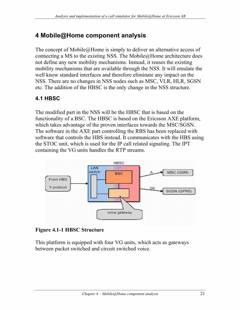
4.1 HBSC The modified part in the NSS will be the HBSC that is based on the functionality of a BSC. The HBSC is based on the Ericsson AXE platform, which takes advantage of the proven interfaces towards the MSC/SGSN. The software in the AXE part controlling the RBS has been replaced with software that controls the HBS instead. It communicates with the HBS using the STOC unit, which is used for the IP call related signaling. The IPT containing the VG units handles the RTP streams.
Figure 4.1-1 HBSC Structure This platform is equipped with four VG units, which acts as gateways between packet switched and circuit switched voice.
Chapter 4 – Mobile@Home component analysis 21
Analysis and implementation of a call simulator for Mobile@Home at Ericsson AB
4.2 HBS The functionality of the HBS is to create a speech or data connection between the MS and HBSC by providing the MS with hotspots using Bluetooth radio technology. This creates a radio coverage area that extends the existing GSM coverage. This is accomplished by using Bluetooth towards the MS and IP toward the HBSC. The voice generated from the MS will be routed as IP packets from the HBS to the HBSC, where the voice is converted into a circuit switched connection towards the MSC. From this point the voice calls will be handled as ordinary GSM calls. The HBS is owned and controlled by the end user, this means that it can be moved and placed anywhere. The implication of a moving HBS is that some automatic configuration procedure of the unit is needed, and that cell planning is not possible. It also prevents the possibility of management procedures to group the HBS units into location areas. The smallest part in a GSM structure is the cell, which is uniquely and individually defined. A group of geographically related cells will define a LA (Location Area). In the GSM system, the LA has a global identifier, LAI (Location Area Identication), which points out a specific area. The LAI contains the following: LAI = MCC + MNC + LAC MCC = Mobile Country Code (same as IMSI MCC) MNC = Mobile Network Code (same as IMSI MNC) LAC = Location Area Code (16 bits allowing 65536 LA: s per PLMN) An individual cell is identified by the LAI number and its cell id, CI, which defines the Cell Global Identity, CGI: CGI = LAI + CI CI = Cell Identity, is a 16 bit value. In Mobile@Home the Bluetooth coverage area can be seen as a traditional GSM cell, which is under control of each HBS. In a GSM network each cell is uniquely and individually defined, but in Mobile@Home every cell under
22 Chapter 4 – Mobile@Home component analysis
Analysis and implementation of a call simulator for Mobile@Home at Ericsson AB
the same HBSC is uniquely defined with the same identity. Instead, the HBS serial numbers are used in the HBSC to distinguish between HBS units. In the MSC/VLR only the new CGI needs to be added per HBSC in the network. The HBSC does not know about the existence of the HBS until it establishes a connection to it. The working prototypes have no means of authentication in the registration process for the moment, something that will be implemented in the future.
4.3 MS When the MS is powered on, both the GSM and Bluetooth radio interfaces are activated. If no Bluetooth coverage is present by the HBS, the MS will carry out a normal IMSI attach trough GSM. Otherwise, if the MS is inside Bluetooth coverage, the HBS will act as the master of a Bluetooth piconet and automatically discover the MS. In this case the GSM part in the MS will be powered down. This is the preferred connection of the MS. To make this possible, the MS needs first to be paired with the HBS. The MSC/VLR will be updated with the Bluetooth LAI and Cell ID, which is the common CGI for all HBS units under the same HBSC. After a successful attachment the MS is ready to make or receive calls.
Chapter 4 – Mobile@Home component analysis 23
Analysis and implementation of a call simulator for Mobile@Home at Ericsson AB
5 Signaling analysis The signaling involved in Mobile@Home will be simplified and not described in detail due to the private and proprietary nature of the HMAP protocol. Though, the primary messages will be presented. The HMAP protocol can be described as a wrapper for all the signaling that is normally sent over the Abis-interface in the GSM network. Instead of sending the messages over radio it is sent over IP/TCP. We would also want to make clear that though the HBSC forwards messages from the MSC, we will assume they originate from the HBSC to simplify the signaling routes, the MSC will be considered when appropriate. To start with, we need to get more information and acquainted with the signaling protocol. There are some different stages that need to be considered in order to simulate a valid HBS and attached MS. This includes:
• The Y-interface. • The attachment and registration of the HBS to the HBSC. • The attachment and registration of the MS to the HBS and HBSC. • Keep alive signaling of HBS • Establishment and connection of a call, this includes:
• Originating calls. • Terminating calls.
• Keep alive signaling of MS. • Disconnection of a call.
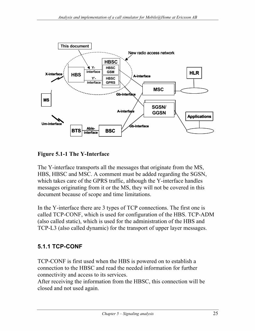
5.1 The Y-interface From the picture below we can see that the Y-interface provides the communication protocol that is of most importance and which will be studied in detail. The X-interface transports the signaling between the MS and HBS using Bluetooth. Though this is carried out by Bluetooth, only the message types are of importance, as we will not implement or simulate the Bluetooth link, only simulate the messages that go through it.
24 Chapter 5 – Signaling analysis
Analysis and implementation of a call simulator for Mobile@Home at Ericsson AB
New radio access network
SGSN/GGSN
HBSCGSM
HBSCGPRS
HBS
MS
HLR
MSC
HBSC
Applications
BSCBTS
A-interface
A-interface
Gb-interface
Gb-interface
X-interface
Um-interfaceAbis-
interface
Y’-interface
Y-interface
This documentNew radio access network
SGSN/GGSN
HBSCGSM
HBSCGPRS
HBS
MS
HLR
MSC
HBSC
Applications
BSCBTS
A-interface
A-interface
Gb-interface
Gb-interface
X-interface
Um-interfaceAbis-
interface
Y’-interface
Y-interface
This document
Figure 5.1-1 The Y-Interface The Y-interface transports all the messages that originate from the MS, HBS, HBSC and MSC. A comment must be added regarding the SGSN, which takes care of the GPRS traffic, although the Y-interface handles messages originating from it or the MS, they will not be covered in this document because of scope and time limitations. In the Y-interface there are 3 types of TCP connections. The first one is called TCP-CONF, which is used for configuration of the HBS. TCP-ADM (also called static), which is used for the administration of the HBS and TCP-L3 (also called dynamic) for the transport of upper layer messages.
5.1.1 TCP-CONF TCP-CONF is first used when the HBS is powered on to establish a connection to the HBSC and read the needed information for further connectivity and access to its services. After receiving the information from the HBSC, this connection will be closed and not used again.
Chapter 5 – Signaling analysis 25
Analysis and implementation of a call simulator for Mobile@Home at Ericsson AB
5.1.2 TCP-ADM TCP-ADM is established right after the TCP-CONF configuration stage. It will remain open as long as the HBS is powered on and working properly. This connection is used for sending keep-alive messages from the HBS to the HBSC to notify its online status and for sending connection-less messages, like paging messages when locating the MS at terminating calls.
5.1.3 TCP-L3 TCP-L3 is established when the MS needs to communicate with the network for sending upper layer messages. It is used for setting up and release user plane calls regarding mobility management, call control, SMS and supplementary service procedures. Some of the upper layer messages are categorized as Layer 3 information, which are transparently transported between the MS and the MSC. This part of the protocol is called DTAP (Direct TrAnsfer information Part) in the A-interface. The DTAP information will not be interpreted by the HBS, and as little as possible by the HBSC.
5.1.4 Distinction of messages The messages sent over the Y-interface will be separated by the HMAP protocol by the value of a protocol discriminator, PD, to indicate their type. In reality the HMP protocol distinguishes between three different types of messages, HMAP, DTAP and BGRR for GPRS specific messages. The BGRR messages will be ignored, as they are not included in this assignment. The PD of DTAP will only be used for some upper layer messages. The remaining messages that are sent between the HBS and HBSC will be recognized by the PD value indicating HMAP.
26 Chapter 5 – Signaling analysis
Analysis and implementation of a call simulator for Mobile@Home at Ericsson AB
5.2 HBS connections At the initial connection with TCP-CONF, the HBS provides its identification number and serial number. The HBSC will response with system information necessary for further functionality. This information includes LAI, a control channel description, interval for keep-alive messages, and ports for the dynamic connection and RTP/voice traffic. The HBSC selects one of its several Ethernet interfaces to be associated with the HBS, this is done to achieve load balancing. After receiving the response from the HBSC, the TCP-CONF connection will be closed. The TCP-ADM establishment needs to take place, the HBSC opens the ports for listening, allowing only this particular HBS to connect. If no connection attempt is made within 2 minutes, the ports will be closed and the allocated resources for the HBS will be released. If the connection succeeds, the HBSC will immediately send a message to the HBS, called HBS-Information, which will be saved and not be interpreted. This message contains parameters that will be provided later on to every MS under the control of the HBS. In case of failure in this connection, the HBS will contact the HBSC after a period of 1-240 seconds for a reestablishment of the connection. The HBS will send keep-alive messages towards the HBSC to indicate its online status. If the HBSC have not received any keep-alive message within 2.5 times the interval, the HBSC should consider this as a failure of the connection. In case the HBSC discovers a connection fault it will release all upper resources regarding this HBS. It will also remove all IMSI numbers from its internal database regarding all MS related to this HBS. The HBSC will react almost with the same measures towards the MSC. For the setup of originating user calls, specific update messages from the MS and terminating calls, the dynamic connection will be used. This type of connection is only available during the performance of the service, it will be immediately closed afterwards.
Chapter 5 – Signaling analysis 27
Analysis and implementation of a call simulator for Mobile@Home at Ericsson AB
During a user call, call-alive messages will be sent towards the HBSC to maintain this connection. When a dynamic connection fails, any associated call will be terminated and all resources released.
5.2.1 HBS attachment When powering up the HBS, it goes through 3 different steps: Step 1 – DHCP session: It will first contact the local DHCP server on the local LAN to receive an IP address, subnet mask, default gateway and DNS server addresses. If no answer is received it will assume the IP address 10.0.0.99 and wait for user interaction. Step 2 – DNS session: After receiving a DNS server, it will query the server to resolve the name of the configured primary HBSC name. If that attempt does not succeed, it will try with the secondary HBSC name. This process can go on infinitely. If there is only an IP address to the HBSC configured, that will be used if no names are available. Step 3 – HBSC session Using the IP address received from the DNS server or the pre-configured IP address, the HBS will try to attach to the HBSC using TCP-CONF. If the attachment does not succeed, it will go back to step2.
5.3 MS attachment To communicate with the network the MS uses the upper layer messages through HMAP. Whenever a MS is switched on it will need to register itself towards the network. This is done by carrying out an IMSI attach procedure. The HBS will detect that a new MS is under coverage through the Bluetooth connection. It will forward the information received earlier in the HBS-Information message from the HBSC to the MS. The MS will respond by
28 Chapter 5 – Signaling analysis
Analysis and implementation of a call simulator for Mobile@Home at Ericsson AB
sending its IMSI number to the HBS. This IMSI number will be wrapped into a MS-INFORMATION message and sent to the HBSC from the HBS, which will map the MS to the corresponding HBS. The MS shall also send a Location Update Request to get the right location information where the MS is placed. This message will also assign the MS to the network and adds the IMSI-number to the MSC database. After the IMSI-attachment the MS will follow with a location update message.
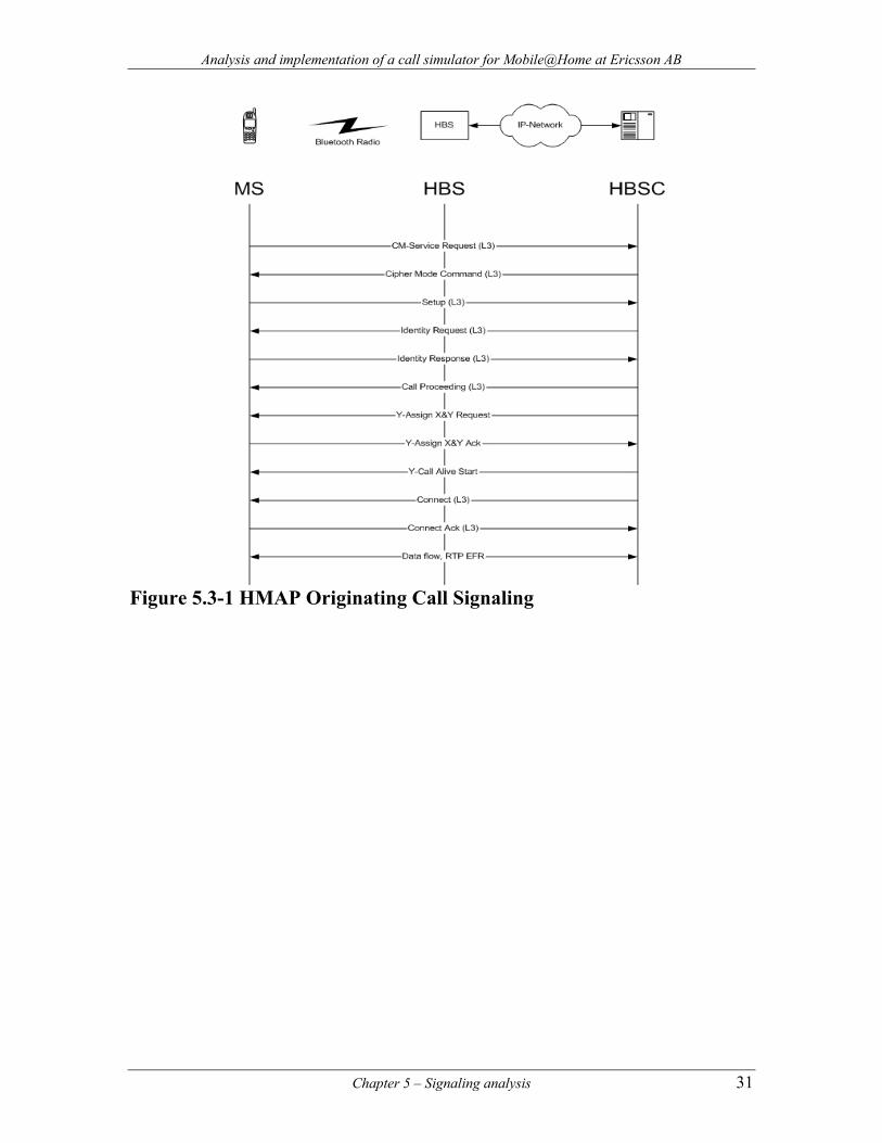
5.3.1 Originating Call When a MS wants to initiate a call it will start by sending a CM-SERVICE-REQUEST, with a PD of DTAP, as it is done in the GSM network to inform the network that the MS needs resources for its call. In this case the HBS will set up a dynamic TCP connection to the HBSC where further messages will be sent during the lifespan of the call, it will then immediately send the CM-SERVICE-REQUEST to the HBSC. The HBS will wrap all the L3 messages received from the MS into HMAP messages and send them to the HBSC. The HBSC will respond with a CIPHER-MODE-COMMAND, with a PD of HMAP, to pass cipher mode information to select an encryption algorithm and load the encryption device with the appropriate key for the user data and signaling. In Mobile@Home no ciphering is used at the moment so the message will be received and ignored by the HBS. This will follow by an IDENTITY-REQUEST message, with a PD of DTAP, from the HBSC to verify the identity of the MS. The MS will send an IDENTITY-RESPONSE message, with a PD of DTAP, containing its IMEI number. If the identity of the MS is validated the call can proceed or otherwise it will be terminated. The MS will follow by sending a SETUP, with PD of DTAP, containing the BCD number to be called. The HBSC will respond with a CALL-PROCEDING, with PD of DTAP, to the MS. The HBSC sends an ASSIGNMENT-REQUEST, with a PD of HMAP, containing the IP-number and UDP-port for the voice upstream. The HBS responds with ASSIGNMENT-ACKNOWLEDGE, with a PD of HMAP,
Chapter 5 – Signaling analysis 29
Analysis and implementation of a call simulator for Mobile@Home at Ericsson AB
containing its IP-number and a UDP-port for the receiving of the voice downstream. The HBSC sends a CALL-ALIVE-START message, with a PD of HMAP, to inform the HBS as when to send CALL-ALIVE messages. Normally, this interval is defined by a few seconds. This is done to indicate the HBSC the active state of the call. The called subscriber will respond with an ALERT message, with a PD of DTAP, to confirm the call and indicate a ringing tone. This message is sent to the calling MS. When the called subscriber answer the call, CONNECT-ACKNOWLEDGE, with a PD of DTAP, will be sent to the caller and the conversation takes place. When one of the MS involved decides to end the call a DISCONNECT message, with a PD of DTAP, will be sent to other MS to indicate the end. The HBSC will send a RELEASE, with PD of DTAP, to indicate the MS the clear of the call. The MS responds with RELEASE-COMPLETE, with a PD of DTAP, as acknowledge. The HBSC sends a CHANNEL-RELEASE, with a PD of HMAP, to clear the user plane call. The HBS send a RELEASE-INDICATION to acknowledge this and closes the dynamic connection.
30 Chapter 5 – Signaling analysis
Analysis and implementation of a call simulator for Mobile@Home at Ericsson AB
Figure 5.3-1 HMAP Originating Call Signaling
Chapter 5 – Signaling analysis 31
Analysis and implementation of a call simulator for Mobile@Home at Ericsson AB
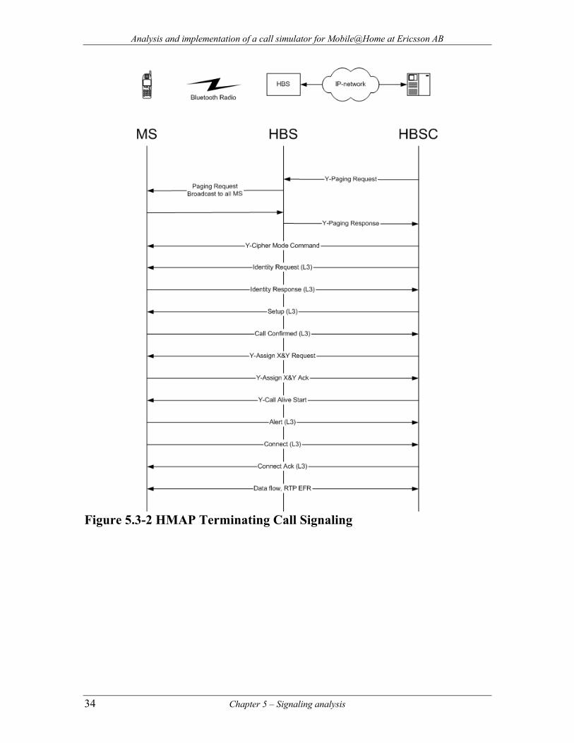
5.3.2 Terminating Call To call a MS, you must first know if it is connected to the network, and then find out where in the network. When a MS is to be called, the HBSC will send a PAGING-REQUEST, with a PD of HMAP. This message contains the IMSI of the MS to be called. The message will be sent to the HBS there the MS is connected. The HBS will broadcast a SYTTEM-INFORMATION message containing the IMSI. If an MS finds that the IMSI is the same as its own, that MS will respond with a PAGING-RESPONSE. The HBSC will respond with a CIPHER-MODE-COMMAND, with a PD of HMAP, to pass cipher mode information to select an encryption algorithm and load the encryption device with the appropriate key for the user data and signaling. In Mobile@Home no ciphering is used at the moment so the message will be received and ignored by the HBS. This will follow by an IDENTITY-REQUEST message, with a PD of DTAP, from the HBSC to verify the identity of the MS. The MS will send an IDENTITY-RESPONSE message, with a PD of DTAP, containing its IMEI number. If the identity of the MS is validated the call can proceed or otherwise it will be terminated. The MS will receive a SETUP from the HBSC, with PD of DTAP, containing the BCD number of the called MS. The MS will respond with a CALL-CONFIRMED, with PD of DTAP, to the MS. The HBSC sends an ASSIGNMENT-REQUEST, with a PD of HMAP, containing the IP-number and UDP-port for the voice upstream. The HBS responds with ASSIGNMENT-ACKNOWLEDGE, with a PD of HMAP, containing its IP-number and a UDP-port for the receiving of the voice downstream. This is done to indicate the HBSC the active state of the call. The HBSC sends a CALL-ALIVE-START message, with a PD of HMAP, to inform the HBS as when to send CALL-ALIVE messages. Normally, this interval is defined by a few seconds. The MS will send an ALERT message, with a PD of DTAP, to confirm the call and indicate a ringing tone. This message is sent to the calling MS. When the called subscriber answer the call, CONNECT-ACKNOWLEDGE,
32 Chapter 5 – Signaling analysis
Analysis and implementation of a call simulator for Mobile@Home at Ericsson AB
with a PD of DTAP, will be sent to the caller and the conversation takes place. When one of the MS involved decides to end the call a DISCONNECT message, with a PD of DTAP, will be sent to other MS to indicate the end. The HBSC will send a RELEASE, with PD of DTAP, to indicate the MS the clear of the call. The MS responds with RELEASE-COMPLETE, with a PD of DTAP, as acknowledge. The HBSC sends a CHANNEL-RELEASE, with a PD of HMAP, to clear the user plane call. The HBS send a RELEASE-INDICATION to acknowledge this and closes the dynamic connection. If the MS is available, the HBS sends back a PAGING-RESPONSE. The MS needs to be located at first, the HBSC will send a PAGING-REQUEST, with a PD of HMAP. If the MS is available, the HBS sends back a PAGING-RESPONSE. If the MS can handle the requested service, it sends a CALL-CONFIRIMED message back to the HBSC. There is no error handling in the HMAP protocol. If an error occurs, it shall trigger the release of the associated call.
Chapter 5 – Signaling analysis 33
Analysis and implementation of a call simulator for Mobile@Home at Ericsson AB
Figure 5.3-2 HMAP Terminating Call Signaling
34 Chapter 5 – Signaling analysis
Analysis and implementation of a call simulator for Mobile@Home at Ericsson AB
6 Design
6.1 Program design Our program will simulate both the HBS and MS. This is done to achieve a unified and simple program, instead of separating the functionality of each unit in different programs. Not only does it simplify our work, it provides a single instrument for the purpose of traffic generation and presentation of its statistics. The program will be separated in different modules that will reflect the behavior of the HBS and MS. This is done to approach a logical and modulated design that will give a better overall structure to the program [44]. It will at the same time ease the coding as we can concentrate on specific parts and distribute the work. We decided to follow and reflect their actual functionality as much as possible, in such extend that they do not behave or act in an unexpected way. Our intention is that the real HBSC will react as if the simulator is just another HBS with attached MS. This will be done without any kind of addition or changes in the HBSC. Considering that both units coexist together under the same program, some simplifications have been made, either to minimize work or bypass difficult stages in the process of the simulation. Any obvious changes will be explained, as why they where done. As the latest generation of programmers, we have normally done every project of mid-to-big size with the object-oriented methodology. When knowing and mastering this programming style, it is regularly easy to structure the program in a multitude of independent pieces. This offers a well-ordered design for separating different parts. It offers features like, identity, classification, polymorphism and inheritance. These are great features that provide a natural foundation for building software. Most of the modern programming languages offer the ability to develop with the object-oriented concept. This is not the case in our situation, the C language that is used in this project, does not support it. There is a variant called Objective-C that gives the possibility, but this option was not considered, we decided to experience something new. The C language was
Chapter 6 – Design 35
Analysis and implementation of a call simulator for Mobile@Home at Ericsson AB
not entirely new for neither of us. We did have some earlier experience, but none that implicated the design of an entire program with this language. This offered a new challenge. Different forms of modeling the program were considered and tested before settling down for a given structure. We started out with a very simple design for testing the basic functionality to get a better understanding of the interconnections between the units involved. As we progressed and the program started evolving, it became clear that it was difficult to achieve a good overall structure that permitted a clean view over the program. It also became obvious that future features or enhancements were going to be hard to integrate. This demanded for a different and more flexible approach. One of reasons behind the difficulty of maintaining a good structure is the event driven nature of the simulator. It has to respond to different events, either from the HBS, MS or HBSC. It was difficult to separate their functionality and maintain them isolated from each other. After some guidance and reading, regarding our problem, we considered to study the form of event driven sequential programming [45]. A sequential program [46] is essentially made up of a number of individual assignments that are put together by means of various constructs: conditional statements, sequential compositions and loops. The role of such constructs is to explicitly schedule these assignments in a proper order so that the execution of the program can achieve its intended goal. With this second approach, event driven sequential programming, separation of actions is handled in a more distributed fashion, no centralized organization is present. The individual assignments are separated from their scheduling, because the synchronization of events is not of primary concern. Instead it is done by a scheduler that organizes and fires them by time. This has to be done in a disciplined manner. To accomplish this event driven process we take advantage of callback functions [35]. With their help, functions can be associated with specific events that are executed according to their scheduled time. As events take place, they are placed into a queue. This queue is stored in order, based on the times the event should occur, so the smallest element will always be the next event to be executed. Execution continues until all events have been processed.
36 Chapter 6 – Design
Analysis and implementation of a call simulator for Mobile@Home at Ericsson AB
The advantages this presents, is that is gives us freedom to refine pieces of the program, and also to create new ones, without being disturbed by others. The program is developed by means of little independent parts that are systematically put together at the end of the process. Considering that Mobile@Home is still under development, more changes and features will be introduced with time. Hence, it is of great importance that the program is flexible enough to reflect these changes. From the current system specification 1.2 to the next one that will be numbered 2.0, there will be some noticeable innovations. This could impact the current design. Our belief is that a good design from the beginning will pay back later. Because of the characteristics about this program, being a test-bench for call simulation, it will be used in different environments. The program could be used in different sites where other operating systems are the norm. This could either be other Linux distributions or UNIX systems. Therefore, our goal is to develop in such a way that will ease the portability of the program, making it available over o broader set of systems. Although, this reduces the portability to only Linux or UNIX like systems. This is the platform of our concern.
6.2 Simulator functionality The simulator starts by creating a specified number of HBS: s and MS: s per HBS. It then proceeds to attach the HBS: s to the HBSC. After this step, the MS: s will be attached to its corresponding HBS, which will register them at the HBSC. This is the first stage of the simulator, create and register all components towards the HBSC and core network. When the first stage is concluded the second stage consists of making the MS: s of each HBS calls the equivalent MS at the HBS with a number less than itself. More specifically, MS number 1 at HBS with number 2 will call MS number 1 at HBS with number 1. This approach was selected to ensure that the HBS and corresponding MS to which a call will be made are correctly registered. There are number of parameters that can be set, which affect the duration of a call, waiting time between calls, time between attachments of HBS and
Chapter 6 – Design 37
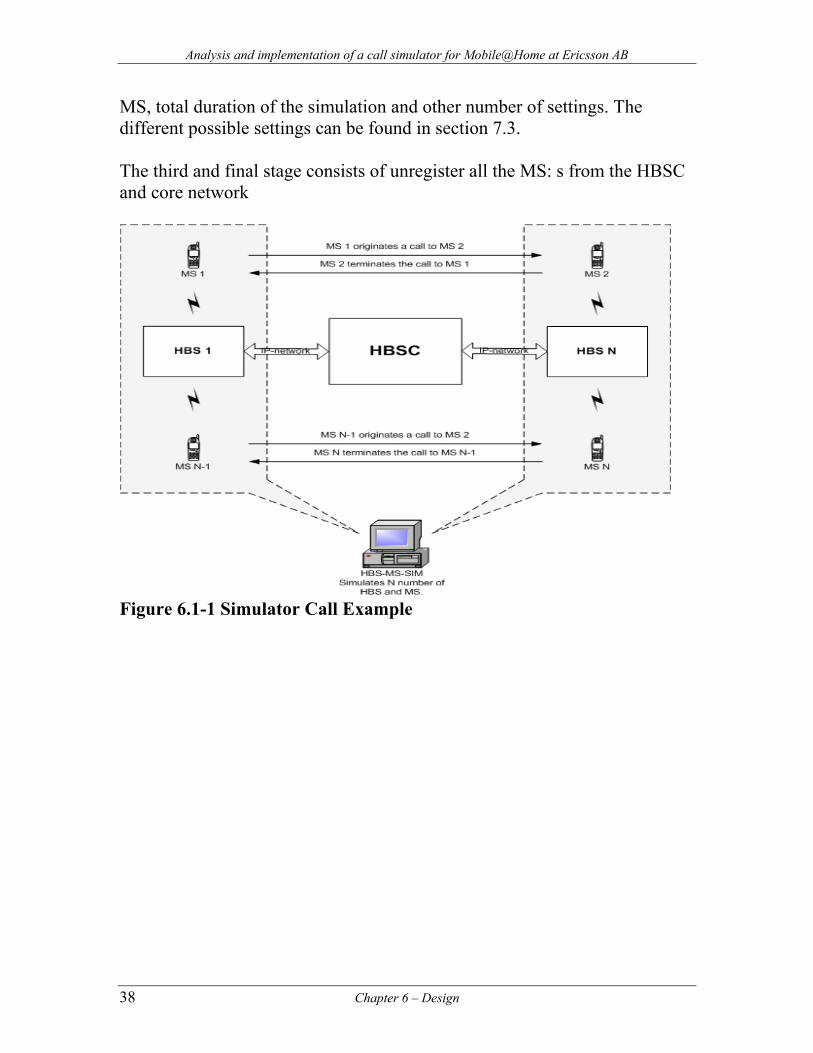
Analysis and implementation of a call simulator for Mobile@Home at Ericsson AB
MS, total duration of the simulation and other number of settings. The different possible settings can be found in section 7.3. The third and final stage consists of unregister all the MS: s from the HBSC and core network
Figure 6.1-1 Simulator Call Example
38 Chapter 6 – Design
Analysis and implementation of a call simulator for Mobile@Home at Ericsson AB
7 Implementation
7.1 RTP library To send and receive voice we are using the RTP-protocol over UDP/IP. After considering a number of different RTP libraries, we have chosen oRTP [15], which is an open source library for handling RTP. oRTP was written primarily to be the RTP stack for Linphone [21], a SIP compatible internet phone for Linux. This is an open source implementation of the RTP [23] specification.
This library contains all necessary functions for sending and receiving RTP-packets. It is written in C which simplifies its integration with our application and it fulfils the most important requirements we need like:
- Support for multiple profiles
- Implements blocking and non-blocking IO for RTP sessions.
- Jitter buffer
- The API is well documented
- Recent updates
- Ongoing development
- Mailing list for support
According to the homepage it is based on glib [22] for portability on most UNIX compatible systems and Microsoft Windows. This makes it appropriate if our application needs to be ported to another platform. The voice is coded in small packages and is sent every 40 ms. To handle this timing requires quite much performance of the program. This was one of the challenges in the implementation of the simulator. The problem is in how the program shall meet all deadlines every 40 ms. We found a good way of multiplexing the incoming data with the select function. For sending every 40 ms, we use the scheduler which is implemented using a binary heap as data structure.
Chapter 7 – Implementation 39
Analysis and implementation of a call simulator for Mobile@Home at Ericsson AB
7.1.1 Payload The simulator supports the following codec’s: - G.711 - EFR We started to implement the G.711 codec. In order to get the RTP-library, oRTP, to handle the codec, we had to create a payload profile for G.711. The library has a special file for handling audio and video payloads, called avprofile.c. This payload is quite straight-forward and does a good work with good voice quality. A clear disadvantage is the bandwidth which is quite high, 65 kbit. A codec with low bandwidth and good voice quality is EFR, Enhanced Full Rate. This codec has a bandwidth of 13 kbit, which is better than G.711. This makes it more appropriate for the network as it uses fewer resources. This codec is the default used in the simulator.
7.2 Simulator modules: The simulator is divided into several modules:
• hbs-ms-sim.c • sched.h/.c • putils.h/.c • connection.h/.c • hbs.h/.c • ms.h/.c • hmap.h/.c • print.h/.c • utils.h/.c • fileparser.h/.c • rtpsend.h/.c • a3a8.h/.c • hbsmssim.conf
40 Chapter 7 – Implementation
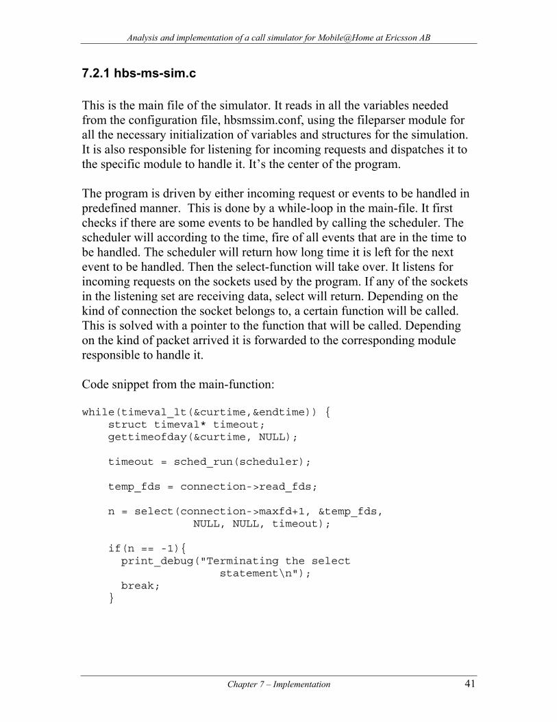
Analysis and implementation of a call simulator for Mobile@Home at Ericsson AB
7.2.1 hbs-ms-sim.c This is the main file of the simulator. It reads in all the variables needed from the configuration file, hbsmssim.conf, using the fileparser module for all the necessary initialization of variables and structures for the simulation. It is also responsible for listening for incoming requests and dispatches it to the specific module to handle it. It’s the center of the program. The program is driven by either incoming request or events to be handled in predefined manner. This is done by a while-loop in the main-file. It first checks if there are some events to be handled by calling the scheduler. The scheduler will according to the time, fire of all events that are in the time to be handled. The scheduler will return how long time it is left for the next event to be handled. Then the select-function will take over. It listens for incoming requests on the sockets used by the program. If any of the sockets in the listening set are receiving data, select will return. Depending on the kind of connection the socket belongs to, a certain function will be called. This is solved with a pointer to the function that will be called. Depending on the kind of packet arrived it is forwarded to the corresponding module responsible to handle it. Code snippet from the main-function: while(timeval_lt(&curtime,&endtime)) { struct timeval* timeout; gettimeofday(&curtime, NULL); timeout = sched_run(scheduler); temp_fds = connection->read_fds; n = select(connection->maxfd+1, &temp_fds,
NULL, NULL, timeout); if(n == -1){ print_debug("Terminating the select
statement\n"); break; }
Chapter 7 – Implementation 41
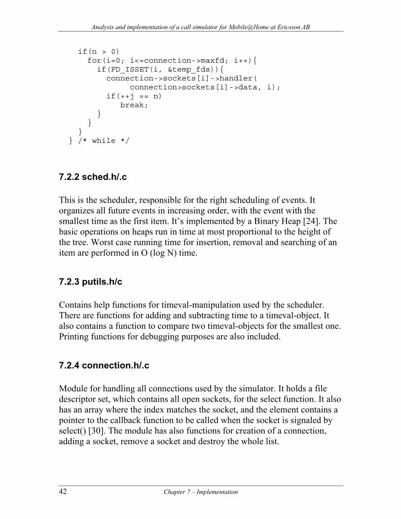
Analysis and implementation of a call simulator for Mobile@Home at Ericsson AB
if(n > 0) for(i=0; i<=connection->maxfd; i++){
if(FD_ISSET(i, &temp_fds)){ connection->sockets[i]->handler(
connection>sockets[i]->data, i); if(++j == n) break;
} } } } /* while */
7.2.2 sched.h/.c This is the scheduler, responsible for the right scheduling of events. It organizes all future events in increasing order, with the event with the smallest time as the first item. It’s implemented by a Binary Heap [24]. The basic operations on heaps run in time at most proportional to the height of the tree. Worst case running time for insertion, removal and searching of an item are performed in O (log N) time.
7.2.3 putils.h/c Contains help functions for timeval-manipulation used by the scheduler. There are functions for adding and subtracting time to a timeval-object. It also contains a function to compare two timeval-objects for the smallest one. Printing functions for debugging purposes are also included.
7.2.4 connection.h/.c Module for handling all connections used by the simulator. It holds a file descriptor set, which contains all open sockets, for the select function. It also has an array where the index matches the socket, and the element contains a pointer to the callback function to be called when the socket is signaled by select() [30]. The module has also functions for creation of a connection, adding a socket, remove a socket and destroy the whole list.
42 Chapter 7 – Implementation
Analysis and implementation of a call simulator for Mobile@Home at Ericsson AB
7.2.5 hbs.h/c Module responsible for the functionality of the HBS. It consists of a structure containing variables used by the HBS and functions to perform different actions depending on a specific event related to a HBS. This module is responsible for all data-handling and all connections related to HBS. It also handles the RTP-sending and receiving. Here is the core functionality for HBS.
7.2.6 ms.h/c This module is responsible for the functionality of the MS. It consists of a structure containing variables used by the MS and functions to perform different actions depending on a specific event related to a MS.
7.2.7 hmap.h/c Module that handles all the HMAP signaling. It is used to create, send and read HMAP messages. This is the connection to the Y-interface. Both HBS and MS use this module to read, create and send messages.
7.2.8 print.h./c This module contains the functions responsible for the print statements that the simulator generates. Depending on the arguments sent to the program, it will present the user with different information. It has three levels of printing: INFO: for the most basic information, this describes what the simulator is doing. ERROR: this presents only the errors that have occurred during a simulation. DEBUG: this print detailed information about internal structures. Its value is of great importance for debugging and testing purposes.
Chapter 7 – Implementation 43
Analysis and implementation of a call simulator for Mobile@Home at Ericsson AB
7.2.9 utils.h/c Module that contains help functions for the entire simulator. They are here for various reasons, either to extract similar functionality repeated in various places or to clean functions or modules from clutter.
7.2.10 fileparser.h/c Module that reads and parse the configuration file, hbsmssim.conf, to obtain the variables to be used during a simulation. It stores the information in a structure. This information is later retrieved with functions that this module provides to other modules.
7.2.11 rtpsend.h/c This module contains the functionality of only sending a RTP-stream towards a specified destination. Either G.711 or EFR coded voice can be sent. This stream is invoked by adding the argument “-rtp” when starting the program. No signaling will be generated.
7.2.12 a3a8.c This module contains the A3 and A8 algorithms [25] [31]. The A3 algorithm is used to generate a valid SRAND value together with a ciphering key (Ki) when receiving a RAND value from the MSC/VLR. This permits the simulator to authenticate all the MS towards the GSM network. The A8 algorithm has no special value at the moment. This module was used during a testing period when authentication was enabled. It is not part of the simulator at the current moment. It is available just in case this functionality is needed in the future.
7.2.13 hbsmssim.conf This is the configuration file for the simulator. Here is where various options can be set for a specific simulation. See the next section for more details regarding the options available.
44 Chapter 7 – Implementation
Analysis and implementation of a call simulator for Mobile@Home at Ericsson AB
7.3 Configuration Options This file, called hbsmssim.conf, is used to set various options when running a simulation. The options have to be set before running the program. Changes can not be made while the program is running. The options are divided into different categories: Common options: RUNNING-TIME-OF-SIM This specifies how long a simulation is to be run in minutes. HBSC options: HBSC-IP The IP number of the HBSC to test. CONF-PORT The TCP port where the HBS will attach to for configuration information. HBS options: HBS-NUMBER The number of HBS that will be created. MS options: MS-NUMBER-PER-HBS The number of MS every HBS should have under its control.
Chapter 7 – Implementation 45
Analysis and implementation of a call simulator for Mobile@Home at Ericsson AB
CALLING-MODE This value sets the calling mode for all MS, there are three different modes available:
• 0 = One half of the total amount of MS will originate calls, and the other half will terminate the calls.
• 1 = all MS will originate calls. • 2 = all MS will terminate calls.
TIME-BETWEEN-CALLS This value sets the duration of a call between to MS in seconds. IMSI-START This value sets the starting number of a range of IMSI numbers. IMSI-MAX-NR This value sets the ending number of the range of IMSI numbers. BCD-START This value sets the start number of the BCD numbers. It is related to the IMSI numbers. RTP options: RTP-FILE-TO-SEND The name of the voice coded file that is going to be sent via RTP. RTP-FILE-TO-RECV This value is used to name the file that is going to receive and save an incoming RTP stream. If the value is set to “NO” no file will be created and no RTP writing will be done. If a name is entered, the simulator will take care of creating the file.
46 Chapter 7 – Implementation
Analysis and implementation of a call simulator for Mobile@Home at Ericsson AB
SPEECH-FRAMES-PER-RTP This value sets the number of speech frames that will be sent in one RTP packet. RTP-JITTER-BUFFER This value sets the jitter buffer in milliseconds.
Chapter 7 – Implementation 47
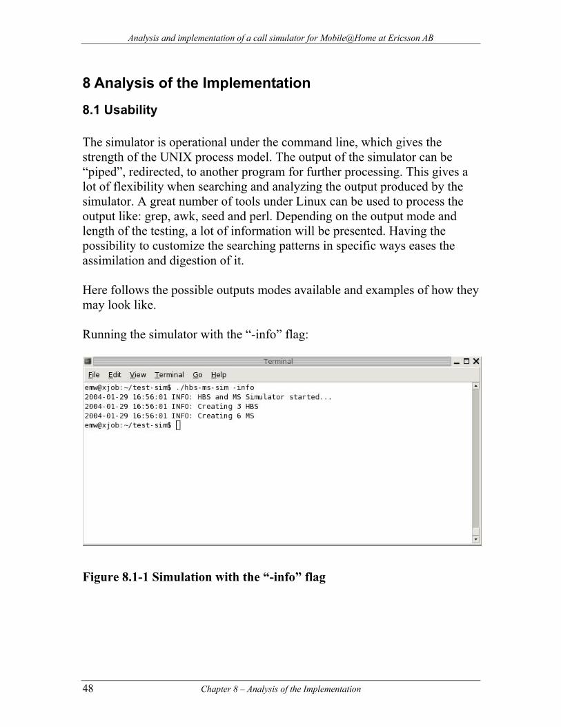
Analysis and implementation of a call simulator for Mobile@Home at Ericsson AB
8 Analysis of the Implementation
8.1 Usability The simulator is operational under the command line, which gives the strength of the UNIX process model. The output of the simulator can be “piped”, redirected, to another program for further processing. This gives a lot of flexibility when searching and analyzing the output produced by the simulator. A great number of tools under Linux can be used to process the output like: grep, awk, seed and perl. Depending on the output mode and length of the testing, a lot of information will be presented. Having the possibility to customize the searching patterns in specific ways eases the assimilation and digestion of it. Here follows the possible outputs modes available and examples of how they may look like. Running the simulator with the “-info” flag:
Figure 8.1-1 Simulation with the “-info” flag
48 Chapter 8 – Analysis of the Implementation
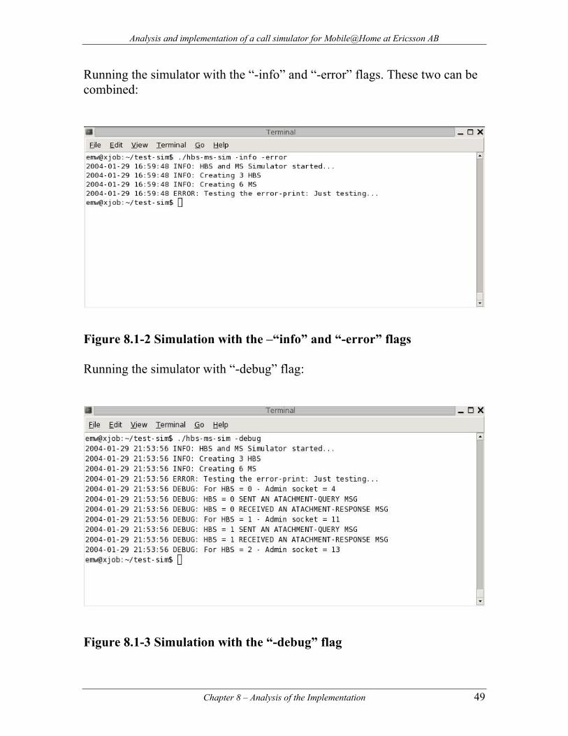
Analysis and implementation of a call simulator for Mobile@Home at Ericsson AB
Running the simulator with the “-info” and “-error” flags. These two can be combined:
Figure 8.1-2 Simulation with the –“info” and “-error” flags Running the simulator with “-debug” flag:
Figure 8.1-3 Simulation with the “-debug” flag
Chapter 8 – Analysis of the Implementation 49
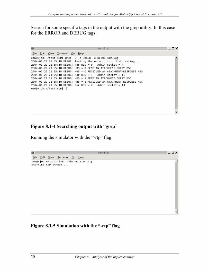
Analysis and implementation of a call simulator for Mobile@Home at Ericsson AB
Search for some specific tags in the output with the grep utility. In this case for the ERROR and DEBUG tags:
Figure 8.1-4 Searching output with “grep” Running the simulator with the “-rtp” flag:
Figure 8.1-5 Simulation with the “-rtp” flag
50 Chapter 8 – Analysis of the Implementation
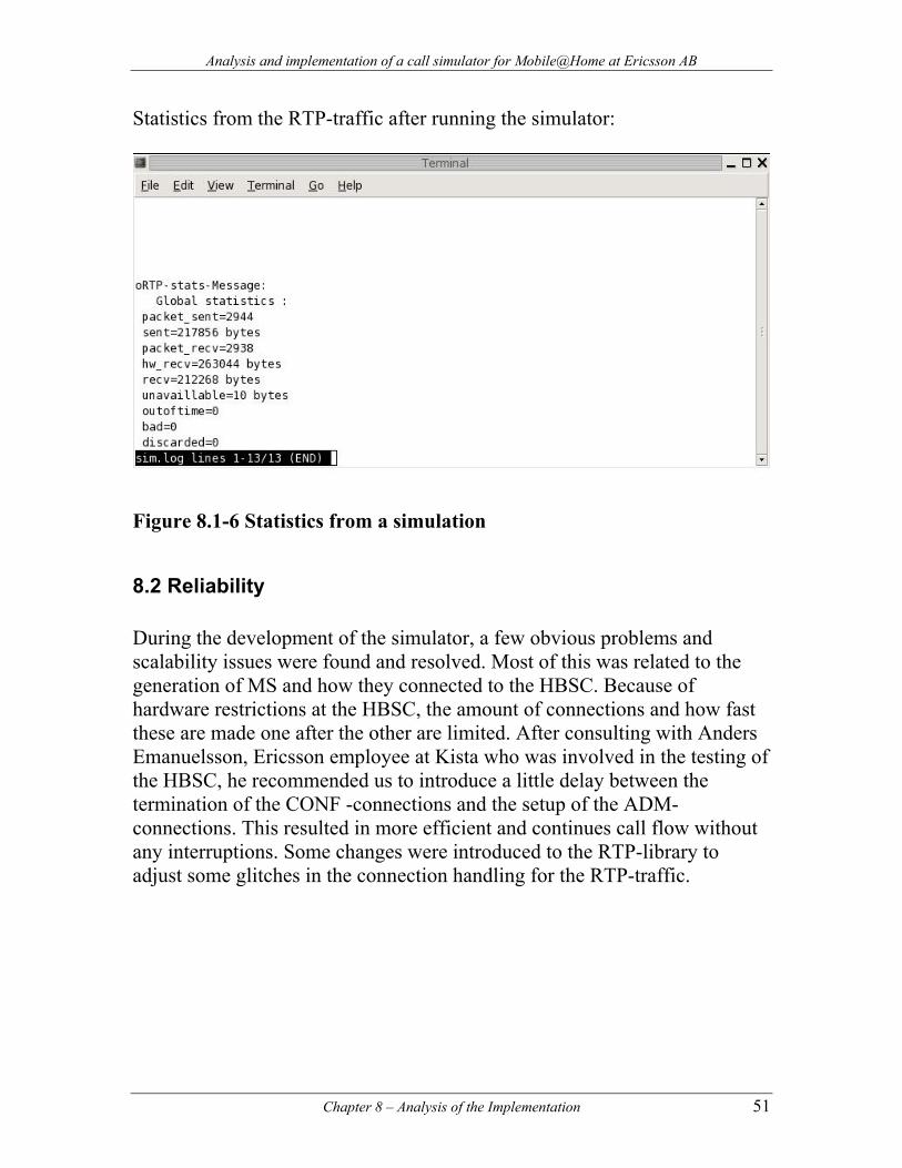
Analysis and implementation of a call simulator for Mobile@Home at Ericsson AB
Statistics from the RTP-traffic after running the simulator:
Figure 8.1-6 Statistics from a simulation
8.2 Reliability During the development of the simulator, a few obvious problems and scalability issues were found and resolved. Most of this was related to the generation of MS and how they connected to the HBSC. Because of hardware restrictions at the HBSC, the amount of connections and how fast these are made one after the other are limited. After consulting with Anders Emanuelsson, Ericsson employee at Kista who was involved in the testing of the HBSC, he recommended us to introduce a little delay between the termination of the CONF -connections and the setup of the ADM-connections. This resulted in more efficient and continues call flow without any interruptions. Some changes were introduced to the RTP-library to adjust some glitches in the connection handling for the RTP-traffic.
Chapter 8 – Analysis of the Implementation 51
Analysis and implementation of a call simulator for Mobile@Home at Ericsson AB
8.3 Performance During the time of tests, the performance of the simulator has been predictable and analogous to the behavior of the real equipment. Performance-wise, no anomalies were found. Because of hardware limitation in the HBSC, the amount of possible calls was restricted. In our tests, we made 12 successful calls, which mean 24 connected MS. This restriction is related to the IPT were only 24 codec’s were available for all MS. Every call, between 2 MS requires 2 codec’s, which gives a maximum of 12 calls. Though no extensive testing was made, due to time limitations, we did not find or encounter restrictions for the amount HBS: s that could be attached towards the HBSC. We need to keep in mind that we never passed more than 100-200 connected HBS: s, something the HBSC should not have problems to handle.
8.4 Scalability We did not perceive any obvious problems while introducing new functionality and enhancements into the simulator. Considering the low amount of calls that are possible today, it is difficult to exactly determine how many ongoing calls, the maximum value, that is possible at this moment. Though, it should not be a problem to increase this number a few times. No special changes need to be done to accomplish this. The simulator is made to adapt itself to these changes as long as the amount of configuration data and right parameters, set at the configuration file, is present. Depending on the amount or impact of changes the design might not hold as it is today. There is a considerable maximum of 1024 simultaneous connections the simulator can handle. This is due to the select() call, it can only handle that number of sockets. If more connections are needed it is possible to increase this number by changing the FD_SETSIZE value in types.h and posix_types.h under /user/include and recompiling the kernel. Though, it needs to be said that this is not a nice or portable way to do it.
52 Chapter 8 – Analysis of the Implementation
Analysis and implementation of a call simulator for Mobile@Home at Ericsson AB
8.5 Memory management The simulator is a test tool, which needs to be reliable if the results are to be trusted. At the same time, it is by no standards a “mission-critical” application. Considering that the amount of code grew rapidly and evolved continuously, a few minor memory leakages are present which do not impact the functionality to a big degree. The C language is notorious for the deep controls of memory management it leaves to the developer [26] [27]. At the same time it is dangerous if not handled properly and it is difficult to debug. Therefore, unfortunately, some glitches are present. We concentrated our effort on other parts we felt were more important due to time limitations.
8.6 Security Considering that the simulator is a testing tool, there is no need for special measures of protecting confidentiality, integrity and availability of the information. Data exchanged with external nodes within the test network to Kista is internal in the Ericsson network. No considerable risks should be imposed when the IP-network used is only available for internal use at Ericsson. It is separated from the public networks like the Internet. It is possible today to sniff the RTP-traffic with tools like RTP-SCAN [28], which can be used to convert raw RTP packets into a decoded wav audio file. This should not be of concern, as the information sent has no important value. This will be solved later on as IPsec is implemented in a later release when going commercial.
8.7 Conclusions and problems We succeeded to produce a simulator that creates a number of HBS with associated MS. This tool achieves its intended goal, generate HMAP signaling and voice traffic towards the HBSC to test its performance and reliability. At the end of a simulation, information and statistics describing the traffic are presented.
Chapter 8 – Analysis of the Implementation 53
Analysis and implementation of a call simulator for Mobile@Home at Ericsson AB
Initial decomposition of the different components and traffic analysis did not yield a valid representation. The test equipment and software did not meat the current specification and its functionality was not entirely correct. During the testing of the HBSC we discovered a few limitations that are probably resolved by this time. These were related to the HMAP signaling, RTP-traffic and the HBSC hardware. More specifically the HBSC could not handle at a first stage the fast amount of attaching connections we started towards it. The HBSC reacted badly when terminating a call without proper teardown of the ongoing call. A problem in the ITP and surrounding components never closed the connection. There were also limitations regarding the amount of the RTP-traffic the HBSC hardware could handle. It has been a challenge to come up with a clean design that provided us to get a good overview over the different components involved and which would integrate gracefully. The design of the simulator should provide an easy transition when updating and adding new functionality of the upcoming specifications. As we have stated earlier, there was not enough time to test the HBSC in depth during our last days at Ericsson, some changes needed to be done at the HBSC. The real test-equipment in the lab did not work during our simulations, because of the heavy load introduced during testing of the simulator. The mobile phones replied with “network busy” messages, indicating that the maximum amount of calls was reached. Other signs of the heavy load became visible when the sound quality deteriorated using the test phones, only one participant would receive voice or no voice at all. There is still some improvements that can be made to the simulator, this will be point out below.
8.8 Future Work As always, the program can become even more robust and improved. Some code can be optimized and cleaned, specially the memory management. An evaluation of the data structures used could reveal better alternatives. Having in mind the enhancements and new functionality for the 2.0 system specification, the simulator should ease the implementation of these. More robust handling for the HMAP messages could be practical when
54 Chapter 8 – Analysis of the Implementation
Analysis and implementation of a call simulator for Mobile@Home at Ericsson AB
introducing new messages. The HMAP protocol is not entirely implemented, a set of messages was left out due to their irrelevance for our assignment. The messages concerning GPRS were not part of the thesis. These should be implemented if GPRS functionality is to be tested. Possible cooperation with the author and developer [29] of the oRTP library could be good step to facilitate modifications, improvements and new functionality. As we did not try other RTP-libraries, comments cannot be made regarding their functionality and performance. It could be good to test them to find another, which is better or a more suitable alternative. More statistics regarding the RTP-streams were discussed during the presentation in Ericsson. Other alternatives could be information regarding the amount of calls that are completed/failed/aborted. As previously stated select() has some scalability issues, in this case the poll() call could be a good replacement as it doesn’t have this restriction. Apparently it has some other nice properties that make it superior to select(). Other improvements would be to randomize numbers like the amount of HBS and MS created, time of attachment to the HBSC, calling length, interval between calls etc…
8.8.1 Authentication No means of security or authentication is used at the moment for the prototype equipment following system specification 1.2. This will change with future releases, requiring a process to authenticate the MS. The necessary algorithm, A3, is already available in an implemented module. The possibility exits that another algorithm is used. It should not be a problem to introduce it as module. Integrating this functionality into the current simulator does not need any cumbersome modifications. Only a few adjustments are necessary. To complete the authentication process, the access to the right Ki-key is imperative, in case for the A3 algorithm to create the correct SRAND values.
Chapter 8 – Analysis of the Implementation 55
Analysis and implementation of a call simulator for Mobile@Home at Ericsson AB
9 References [1] Mobile@Home Introduction
http://dxd.ericsson.se/mah/html/pdf/mah_commercial_white_paper_de10038d.pdf , accessed September 2003
[2] The POSIX standard, http://www.pasc.org, accessed September 2003 [3] Mobile@Home Technical White Paper
http://dxd.ericsson.se/mah/html/pdf/mah_technical_whitepaper_de10466f.pdf, accessed September 2003
[4] Mobile@Home, R1.2, HMAP-protocol specification: formats and
codes. [5] GSM World, http://www.gsmworld.com/index.shtml, accessed
September 2003 [6] System specification GSM for Mobile@Home R1.1 [7] Ericsson GSM system survey, student text EN/LZT 123 332 [8] IMEI introduction, http://www.tele-servizi.com/janus/texts/imei.txt,
accessed October 2003 [9] Ramalho G.711 Lossless (RGL) Codec Whitepaper,
http://www.vovida.org/applications/downloads/rgl/RGL_Whitepaper_1.0.0.html, accessed October 2003
[10] Sorting Through GSM Codecs: A Tutorial,
http://www.commsdesign.com/design_corner/OEG20030711S0010, accessed October 2003
[11] Bluetooth “Specifications of the Bluetooth System”, Core vol.1 v1.1
http://www.bluetooth.com, accessed September 2003 [12] Bluetooth Wireless Technology Overview,
http://archive.devx.com/wireless/articles/Bluetooth/BtoothIntro.asp, accessed September 2003
56 References
Analysis and implementation of a call simulator for Mobile@Home at Ericsson AB
[13] http://williams.comp.ncat.edu/osistack.htm. [14] Internet Protocol. J.Postel (1981). RFC 791. [15] Introducing the Internet Protocols. Caldera International (2001). http://ou800doc.caldera.com/NET_tcpip/CTOC-tcpN.tcpip_intro.html [16] User Datagram Protocol. J. Postel (1980). RFC 768. [17] Transmission Control Protocol. J. Postel (1981). RFC 793. [18] http://www.ssfnet.org/Exchange/tcp/tcpTutorialNotes.html [19] RTP: A Transport Protocol for Real-Time Applications. Audio-Video Transport Working Group et.al. (1996). RFC 1889. [20] http://hagrid.icesi.edu.co/~jmadrid/845proj/node2.html [21] Linphone, http://www.linphone.org, accessed September 2003 [22] Glib, http://www.gtk.org, accessed September 2003 [23] RTP: A Transport Protocol for Real-Time Applications,
http://www.ietf.org/rfc/rfc3550.txt?number=3550, accessed, September 2003
[24] Mark Allen Weiss, Data structures and problem solving using C++ ISBN: 0-8053-1666-3 [25] Implementation of the A3/A8 algorithm, COMP128v1
http://www.iol.ie/~kooltek/a3a8.txt, accessed December 2003 [26] Secure, Efficient and Easy C programming,
http://irccrew.org/~cras/security/c-guide.html, accessed December 2003
[27] Secure Programming for Linux and Unix Howto,
http://www.dwheeler.com/secure-programs/, accessed December 2003
References 57
Analysis and implementation of a call simulator for Mobile@Home at Ericsson AB
[28] RTP-SCAN, http://www.sircd.com, accessed December 2003 [29] Simon Morlat, [email protected] [30] Beejs Network Programming Tutorial,
http://www.ecst.csuchico.edu/~beej/guide/net, accessed 2003-10-22 [31] GSM interception, http://udsab.dia.unisa.it/ads.dir/corso-
security/www/CORSO-9900/a5/Netsec/netsec.html, accessed December 2003
[32] The Vovida RTP implementation, http://www.vovida.org/, accessed
October 2003. [32] Vovida RTP implementation, http://www.vovida.org, accessed
September 2003 [33] Lucent Technologies RTP library, http://www-out.bell-
labs.com/project/RTPlib/, accessed November 2003 [34] Common Multimedia Library,
http://www-mice.cs.ucl.ac.uk/multimedia/software/common/, accessed November 2003
[35] Herbert Schildt, Teach yourself C, third edition [36] The introduction tutorial of VoIP in TLDP,
http://www.tldp.org/HOWTO/VoIP-HOWTO.html, accessed September 2003
[37] Internet Telephony, http://iptel.org/info/, accessed September 2003 [38] Linux Programming Guide, http://www.tldp.org/LDP/lpg/, accessed
2003-10-23 [39] Cygwin, http://cygwin.com, accessed September 2003 [40] Small Business Resources Server 4.5,
http://www.microsoft.com/technet/prodtechnol/sbs/45/default.mspx, accessed September 2003
58 References
Analysis and implementation of a call simulator for Mobile@Home at Ericsson AB
[41] oRTP, http://www.linphone.org/ortp, accessed September 2003 [42] Mobile@Home System specification R1.2 [43] 3GPP TS 24.008 V6.2.0 (2003-09) [44] Jeri Hanley and Elliot B. Koffman, Problem solving and program
design in C [45] Event driven sequential programming,
http://www.matisse.qinetiq.com/pap.pdf, accessed November 2003 [46] How sequential programming is usually taught,
http://www.cs.luc.edu/triveni/papers/poster/sld009.htm, accessed November 2003
References 59
Analysis and implementation of a call simulator for Mobile@Home at Ericsson AB
Appendix A: The README file README: This is the source distribution for the HBS-MS-SIM simulator used within Mobile@Home. Contents -------- 1. Introduction 2. Documentation 3. Requirements 4. Installation and Compilation 5. Configuration Settings 6. Using HBS-MS-SIM 7. Package Contents 8. Authors 1. Introduction --------------- The HBS-MS-SIM is a simulator for the Mobile@Home team. It is used to generate both signaling and voice streams towards the HBSC. The simulator creates a specified number of HBS and MS. The functionality of the simulator behaves almost like any real HBS with attached MS. To the HBSC it will look like any other HBS or MS. For limitation reasons, only GSM signaling has been implemented. It is not valid to simulate or test GPRS traffic. Once the HBS and MS has attached to the HBSC and registered at the MSC they will start calling each other. The signaling is done with the HMAP protocol and the voice stream consists of EFR coded voice within RTP packets, conforming to the RFC-1889. The simulator provides another set of useful functions that will be described later in this document.
60 Appendix A
Analysis and implementation of a call simulator for Mobile@Home at Ericsson AB
2. Documentation ---------------- For more detailed information about the structure and functionality of the HBS-MS-SIM see the report[1] belonging to this simulator. 3. Requirements --------------- For building the simulator from scratch there are several requirements needed. All of this, except Glib, is included with the HBS-MS-SIM tarball. - Glib version > 2.0.0 (http://gtk.org) (used by oRTP) - The HBS-MS-SIM source files. - oRTP library 0.6.2 (http://linphone.org/ortp) NOTE: We have done several changes to the oRTP library, these customizations are not available through the original sources. For best compatibility and correct functionality, use the oRTP sources provided with this distribution. Hopefully these changes will be introduced in the original oRTP library. 4. Installation and Compilation ------------------------------- To build the simulator: 1. Copy the hbs-ms-sim.tar.gz file to the desired location. 2. Unpack by typing the command "tar zxvf hbs-ms-sim.tar.gz". 3. Install the oRTP library: 1. Enter to the oRTP directory and type, one command at the time: "./configure" "make" "make install" (this must be done as root)
Appendix A 61
Analysis and implementation of a call simulator for Mobile@Home at Ericsson AB
2. If everything went well, type as root: "/sbin/ldconfig" After this step, the library will be installed and placed at "/usr/local/lib/". 3. Enter to the new HBS-MS-SIM directory with "cd" and type "make", this will build the simulator. If no errors are printed, the simulator have successfully been built. Otherwise, probably some requirements have not been fulfilled. 5. Configuration Settings ------------------------- Before running the simulator there are several options that can be set in the configuration file, "hbsmssim.conf", that is included with the distribution. A short explanation in the file describes the purpose of every variable. All the variables in the configuration file must have a value. They have currently some default values set for the correct behaviour of the simulator. If some value is missing, the simulator will inform the user. A second configuration file called "hbsmssim.conf_template" has been added if the original one has become damaged. In this case, do a copy of it and set the appropiate values. This can be done by doing the following at the command prompt: "cp hbsmssim.conf_template hbsmssim.conf" For a more detailed explanation regarding the variables see the report[1]. 6. Using HBS-MS-SIM ------------------- There are several command line arguments that can be added when running the
62 Appendix A
Analysis and implementation of a call simulator for Mobile@Home at Ericsson AB
simulator that will change its behavior. We will first explain the various printing modes, which give different print statements. All print statements are preceded with the current time and date. 1. "./hbs-ms-sim" This is the default running mode of the simulator, without any arguments. In this case it is equivalent as running with the "-info" option. See below. 2. "./hbs-ms-sim -info" This will run the simulator with only the print statements labeled as INFO. The INFO statements presents what the simulator is doing, that is, it presents only the minimum and necessary information to the user. 3. "./hbs-ms-sim -error" This option will only present the print statements labeled as ERROR. The ERROR statements informs the user of any errors that have occurred during the simulation. 4. "./hbs-ms-sim -info -error" There is also the possibility to combine this two options. Their order is of no importance at the command line. This will present the print statemenst INFO and ERROR. 5. "./hbs-ms-sim -debug" This option will display all print statements described above and the DEBUG statements. More specifically the INFO, ERROR and DEBUG statements. The DEBUG printouts are of more value for checking the correct behaviour of the simulator and for debugging purposes. 6. "./hbs-ms-sim -rtp"
Appendix A 63
Analysis and implementation of a call simulator for Mobile@Home at Ericsson AB
This option will only send a RTP-stream towards the HBSC. No signaling will be involved. There will not be any creations of HBS or MS. When the simulator has finished, it will present the user with statistics regarding the RTP-streams. This information will be displayed no matter what option has been used at the command line. It will always be displayed. The simulator can be run in three different ways. This is specified within the configurition file, changing the value of CALLING-MODE: 1. CALLING-MODE=0 This will run the simulator with the half numbers of MS as originating callers and the other half as recievers. This is the default setting. For the correct behaviour of a simulation, there must be a even number of MS. 2. CALLING-MODE=1 This will run the simulator with all MS as originating callers. The range of numbers to be called is set with BCD-START. That is, if the simulator is going to call 10 MS it will start with the BCD-START number and increase it with 9 more numbers. 3. CALLING-MODE=2 This will run the simulator with all MS in terminating mode. They will only respond to calls. Depending on the numbers of MS they need the same amount of IMSI and BCD numbers from the configuration file. That is, if 10 MS are going to receive calls, then the simulator will start from the entered IMSI and BCD number from IMSI-START and BCD-START respectively, and increase it with 9 more numbers following the start number. 7. Package Contents -------------------
64 Appendix A
Analysis and implementation of a call simulator for Mobile@Home at Ericsson AB
Here follows a list of all files within the source package: - README - The oRTP library, "ortp-0.6.3pre4.tar.gz" - The files of the simulator: Makefile hbsmssim.conf hbs_ms_sim.c hmap.h hmap.c hbs.h hbs.c ms.h ms.c connection.h connection.c sched.h sched.c putil.h putil.c print.h print.c fileparser.h fileparser.c utils.h utils.c rptsend.h rptsend.c G711.rtp (voice coded with the G711 codec) EFR.rtp (voice coded with the EFR codec)
Appendix A 65
Analysis and implementation of a call simulator for Mobile@Home at Ericsson AB
hbsc-sim.c (a very simple program to only receive a RTP stream, used for testing) a3a8.c (This file implements the A3 algorithm for authentication, but is not part of the simulator at the current moment) 8. AUTHORS ---------- Edvard Wikström E-mail: [email protected] Mobile phone: 0704648182 Rasmus Larsson E-mail: [email protected] Mobile phone: 0706993443 References ---------- [1] Analysis and implementation of a call simulator for Mobile@Home at Ericsson AB. (Last change made 2004-02-06)
66 Appendix A
Analysis and implementation of a call simulator for Mobile@Home at Ericsson AB
Appendix B: The configuration file for the simulator
;========================================= ; Configuration file for the HBS-Simulator. ; ; Max length of a line in this file is 256 ; characters. ;========================================= ;========================================= ; Common variables ;========================================= ; How long the simulator will run ; in minutes. RUNNING-TIME-OF-SIM=2 ;========================================= ; Variables for the HSBC ;========================================= ; The IP address for the attachment to the HBSC. HBSC-IP=192.168.6.22 ; The TCP configuration port of the HBSC. CONF-PORT=14001 ;========================================= ; Variables for the local HBS-Simulator ;========================================= ; Number of HBS HBS-NUMBER=12
Appendix B 67
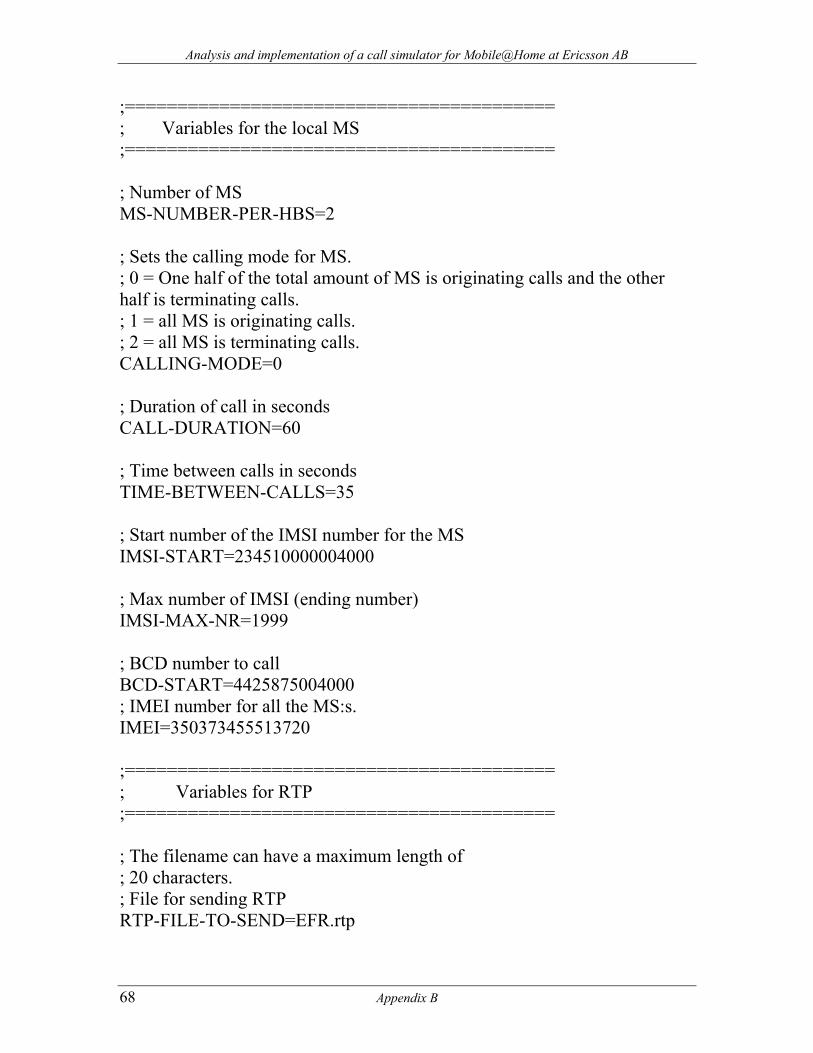
Analysis and implementation of a call simulator for Mobile@Home at Ericsson AB
;========================================= ; Variables for the local MS ;========================================= ; Number of MS MS-NUMBER-PER-HBS=2 ; Sets the calling mode for MS. ; 0 = One half of the total amount of MS is originating calls and the other half is terminating calls. ; 1 = all MS is originating calls. ; 2 = all MS is terminating calls. CALLING-MODE=0 ; Duration of call in seconds CALL-DURATION=60 ; Time between calls in seconds TIME-BETWEEN-CALLS=35 ; Start number of the IMSI number for the MS IMSI-START=234510000004000 ; Max number of IMSI (ending number) IMSI-MAX-NR=1999 ; BCD number to call BCD-START=4425875004000 ; IMEI number for all the MS:s. IMEI=350373455513720 ;========================================= ; Variables for RTP ;========================================= ; The filename can have a maximum length of ; 20 characters. ; File for sending RTP RTP-FILE-TO-SEND=EFR.rtp
68 Appendix B
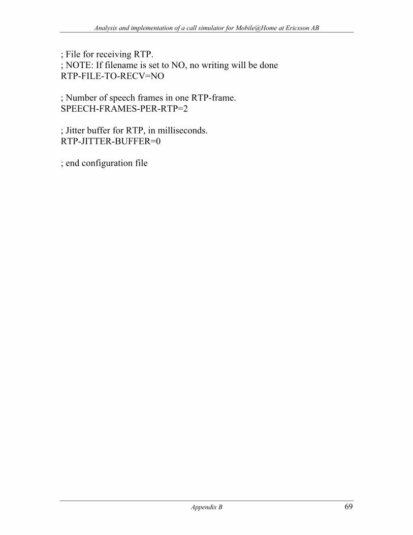
Analysis and implementation of a call simulator for Mobile@Home at Ericsson AB
Appendix B 69
; File for receiving RTP. ; NOTE: If filename is set to NO, no writing will be done RTP-FILE-TO-RECV=NO ; Number of speech frames in one RTP-frame. SPEECH-FRAMES-PER-RTP=2 ; Jitter buffer for RTP, in milliseconds. RTP-JITTER-BUFFER=0 ; end configuration file
På svenska Detta dokument hålls tillgängligt på Internet – eller dess framtida ersättare – under en längre tid från publiceringsdatum under förutsättning att inga extra-ordinära omständigheter uppstår.
Tillgång till dokumentet innebär tillstånd för var och en att läsa, ladda ner, skriva ut enstaka kopior för enskilt bruk och att använda det oförändrat för ickekommersiell forskning och för undervisning. Överföring av upphovsrätten vid en senare tidpunkt kan inte upphäva detta tillstånd. All annan användning av dokumentet kräver upphovsmannens medgivande. För att garantera äktheten, säkerheten och tillgängligheten finns det lösningar av teknisk och administrativ art.
Upphovsmannens ideella rätt innefattar rätt att bli nämnd som upphovsman i den omfattning som god sed kräver vid användning av dokumentet på ovan beskrivna sätt samt skydd mot att dokumentet ändras eller presenteras i sådan form eller i sådant sammanhang som är kränkande för upphovsmannens litterära eller konstnärliga anseende eller egenart.
För ytterligare information om Linköping University Electronic Press se förlagets hemsida http://www.ep.liu.se/ In English The publishers will keep this document online on the Internet - or its possible replacement - for a considerable time from the date of publication barring exceptional circumstances.
The online availability of the document implies a permanent permission for anyone to read, to download, to print out single copies for your own use and to use it unchanged for any non-commercial research and educational purpose. Subsequent transfers of copyright cannot revoke this permission. All other uses of the document are conditional on the consent of the copyright owner. The publisher has taken technical and administrative measures to assure authenticity, security and accessibility.
According to intellectual property law the author has the right to be mentioned when his/her work is accessed as described above and to be protected against infringement.
For additional information about the Linköping University Electronic Press and its procedures for publication and for assurance of document integrity, please refer to its WWW home page: http://www.ep.liu.se/ © [Rasmus Larsson, Edvard Wikström]