Embed Size (px)
Citation preview

IOSR Journal of Electrical and Electronics Engineering (IOSR-JEEE)
e-ISSN: 2278-1676,p-ISSN: 2320-3331, Volume 15, Issue 1 Ser. II (Jan – Feb 2020), PP 42-52
www.iosrjournals.org
DOI: 10.9790/1676-1501024252 www.iosrjournals.org 42 | Page
Analysis and Improvement of Power Quality Parameters by
Using UPQC with the Implementation of Fuzzy and PID
Controllers
Ravindra Kajla1, Subhash
2
1,2Department of Electrical Engineering, Sobhasariya Engineering College, Sikar, Rajasthan, India
Abstract : The advance use of power electronic devices introduces harmonics in the supply system which
creates a problem in the quality of power delivered. Good Power Quality is very much important for our day to
day use of appliances in both industrial and domestic sectors. Researchers have tried and implemented many
useful technologies for removing all the voltage and current related harmonic occurrence problems which in
turn improves the quality of power delivered to the power system. The prime focus of this thesis is the
implementation of control strategies like SRF theory and instantaneous power (p-q) for the operation of Unified
Power Quality Conditioner (UPQC) which is one of the recent technology that includes both series and shunt
active power filter operating at the same time and thereby improves all the current and voltage related problem
like voltage sag/swell, flicker, etc. at the same time and helps in reduction of Total Harmonic Distortion (THD).
In this thesis it is shown via MATLAB simulation how UPQC model can be used to decrease the % THD in
source voltage, source current and load voltage waveforms created due to non-linear/ sensitive loads usage.
Keywords: Power quality, UPQC, THD, sag, swell ----------------------------------------------------------------------------------------------------------------------------- ---------
Date of Submission: 11-02-2020 Date of Acceptance: 26-02-2020
--------------------------------------------------------------------------------------------------------------------------------------
I. Introduction The introduction of the paper should explain the nature of the problem, previous work, purpose, and the
contribution of the paper. The contents of each section may be provided to understand easily about the paper.
For the development of the nation, it is important to adopt economic sources in the form of production.
For this production, factories and industries are established and they are operated on heavy loads and need to run
the main source for running electricity. Efficiency and accuracy is the main focus of this area. For this, supply of
power which is supplied, I should have good quality without any interruption and defect. There is a term for
maintaining demand according to the required load “Power Quality” that must be controlled and managed in any
case.
The heavy weight of the industry gives a harmonic disorder in the system and which affects the overall
parameters of the system to the area of generation. To improve their quality, electrical quality is considered for
voltage, current, frequency and harmonics. However, describing the quality of good power is not easy, because
for a device like a motor which has the quality of power, it cannot be good for our personal computer and other
sensitive loads.
Fig 1 shows the basic structure of power system network and smart utilization of this system respectively.
Fig.1 Basic power system network
1. Causes of deficiency in the power quality
Power quality depends on some parameters and to maintain power quality these parameters and effect of these
parameters are voltage, current and frequency. Causes and effects due to these parameters are
Power System
Generation DistributionTransmission

Analysis and Improvement of Power Quality Parameters by Using UPQC with the Implementation ..
DOI: 10.9790/1676-1501024252 www.iosrjournals.org 43 | Page
(a) Irruptions (b) voltage sag (c) voltage swells (d) Transients (e) Harmonics
A. Interruption
When the power system line voltage or current is less of a blockage, at least 10 percent less than 60 seconds is
reduced in length. As shown in Fig. 2 Another common power-quality event is "Notching", which can be made
by Rectifiers, which is a finite line installation.
Fig.2 Interruption in transmission line voltage waveform
B. Voltage Sag
When the voltage bag / dip is in the electrical system, the RMS line-voltage decreases by 10 to 90
percent of the nominal value of the line-voltage. The standard period of one voltage loosely is 1 minute from 0.5
cycles. Primarily due to the introduction of large induction motors and utility defects. Fig.3. shows the wave
form of sag occurs in system.
Fig.3 Sag in transmission line voltage waveform
C. Voltage Swell
When the voltage is swell in the power system, the RMS line-voltage increases by the nominal value of line-
voltage from 110 to 180 percent. The standard duration of a voltage swell is 0.5 cycles 1 min. White is primarily
due to wrong tape settings in the flaw chamber in line fault and substation
Fig 4. Voltage swell in power system network
Fig 5 Variations in power system
D. Transients and Harmonics
When the power system is transient in line, the voltage and current amplitude vary. The causes for this
are switching of inductive load and distribution system. Fig 6 shows impulsive and oscillatory transients in
power system and fig. 7 shows reduction in harmonics in system. This type of variation damages the system
equipment is as it stays for long time. The power of electronic equipment, such as zener diode or metal oxide
varistor, is used for compensating for transient defects.
Fig.6 Impulsive and oscillatory transients in power system
Analysis and Improvement of Power Quality Parameters by Using UPQC with the Implementation ..
DOI: 10.9790/1676-1501024252 www.iosrjournals.org 44 | Page
Fig. 7 Harmonic reduction in system
E. Voltage Fluctuation
Fig. 8 shows voltage fluctuation waveforms in power system.due to non-synchronization of line frequency with
current parameter, fluctuations in voltage observed. There is small variation due to this fault.
Fig. 8 Voltage fluctuations in power system
A voltage “imbalance” is also results variation in the three-phase voltages; fig.9. shows noise in power system
which is due to imbalance in the system.
Fig. 9. Noise in power system
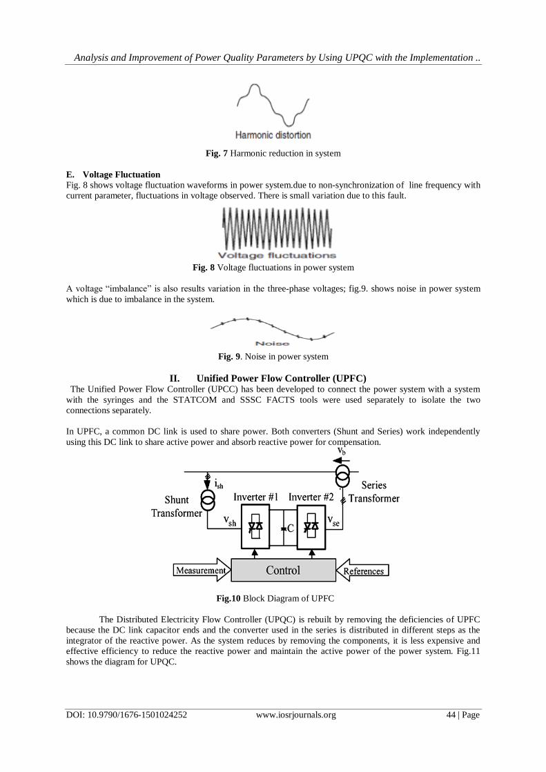
II. Unified Power Flow Controller (UPFC) The Unified Power Flow Controller (UPCC) has been developed to connect the power system with a system
with the syringes and the STATCOM and SSSC FACTS tools were used separately to isolate the two
connections separately.
In UPFC, a common DC link is used to share power. Both converters (Shunt and Series) work independently
using this DC link to share active power and absorb reactive power for compensation.
Fig.10 Block Diagram of UPFC
The Distributed Electricity Flow Controller (UPQC) is rebuilt by removing the deficiencies of UPFC
because the DC link capacitor ends and the converter used in the series is distributed in different steps as the
integrator of the reactive power. As the system reduces by removing the components, it is less expensive and
effective efficiency to reduce the reactive power and maintain the active power of the power system. Fig.11
shows the diagram for UPQC.

Analysis and Improvement of Power Quality Parameters by Using UPQC with the Implementation ..
DOI: 10.9790/1676-1501024252 www.iosrjournals.org 45 | Page
Fig.11. UPQC configuration
SRF controlling method for the operation of UPQC model is very similar to instantaneous reactive
power theory method. A major feature this algorithm pursues is that only load current is essential here for the
generation of reference current and hence disturbances present in source or distortions present in voltage have
will leave no negative impact to the performance of the designed UPQC system. In the given proposed SRF
method for UPQC we have optimized the system without using transformer voltage, load, and filter current
measurement, this reduces numbers of measurements are and thereby improving system performance.
Fig.12 Block Diagram of UPQC
III. Design of the system
The idea used here is to produce harmonic current having components which has 180° phase shift to
the components of harmonic current which are generated by the use of nonlinear loads. The concept is totally
based on injecting harmonic current in the ac system similar in amplitude but opposite in phase when compared
with load current waveform harmonics.
In normal conditions, the source is assumed as a perfect sinusoidal voltage i.e
𝑉𝑠(𝑡) = 𝑉𝑚 sin (𝜔𝑡) (1)
Now we apply a non-linear load and as discussed above, the load current will have both fundamental
component and also harmonics of higher order. This current we represent as:
(2)
Now, the load power is expressed as:-
𝑝𝑙(𝑡) = 𝑉𝑠(𝑡)𝑖𝑙(𝑡) =𝐼1𝑉𝑚𝑠𝑖𝑛2(𝜔𝑡)𝑐𝑜𝑠𝜃1 + 𝐼1𝑉𝑚 sin(𝜔𝑡) cos(𝜔𝑡) 𝑠𝑖𝑛𝜃1 +
=𝑝𝑠(𝑡) + 𝑝𝑐(𝑡) (3)
In eqn. (3)the we define 𝑝𝑠(𝑡) as real power given by utility source, and 𝑝𝑐(𝑡) as the reactive power and the
harmonic power, i.e.

Analysis and Improvement of Power Quality Parameters by Using UPQC with the Implementation ..
DOI: 10.9790/1676-1501024252 www.iosrjournals.org 46 | Page
𝑝𝑠(𝑡) = 𝐼1𝑉𝑠𝑚𝑠𝑖𝑛2(𝜔𝑡)𝑐𝑜𝑠𝜃1
(4)
By discussion above we know that APF will provide the reactive and harmonic power 𝑝𝑐(𝑡), the
current supplied by source is given as :-
(5)
The current 𝑖𝑠(𝑡) is and utility voltage is seen to be in phase and pure sinusoidal. At this time, the APF
will provide the following compensation current in the circuit:
𝑖𝑐(𝑡) = 𝑖𝑙(𝑡) − 𝑖𝑠(𝑡) (6)
IV. Proposed power system Designing and modelling of UPQC is described in this section of thesis. MATLAB/ Simulink (2017a)
is used for designing and analysis. Modelling of various sections with system design is elaborated with
MATLAB circuits and controllers using Fuzzy logic controller.
Fig. 13. Proposed MALTAB model for power system with UPQC and controller
Fig. 14. Proposed MALTAB model for UPQC and controller
Fig. 15. MALTAB model for UPQC with series and shunt converters

Analysis and Improvement of Power Quality Parameters by Using UPQC with the Implementation ..
DOI: 10.9790/1676-1501024252 www.iosrjournals.org 47 | Page
Fig. 16. Shunt controller with PID controller for UPQC
Fig. 17. Shunt controller with fuzzy logic controller for UPQC
Fig. 18. Series controller with PID controller for UPQC
Fig. 19. Series controller with fuzzy logic controller for UPQC

Analysis and Improvement of Power Quality Parameters by Using UPQC with the Implementation ..
DOI: 10.9790/1676-1501024252 www.iosrjournals.org 48 | Page
Fig. 20. Power generation source for proposed system
V. Results with PID and Fuzzy Logic Controller
Results in the form of waveforms are presented in this section by taking parameters of shunt, series
voltage and current along with grid parameters. In last sections total harmonic distortion and comparison of PID
and FLC results are shown.
A. Grid Voltage and Current
Fig 21. Grid Voltage and current of system using PID controller
Fig 22. Grid Voltage and current of system using FLC controller
Fig. 21. and 22. shows grid voltage and current of proposed system with UPQC with implementation of
PID and FLC respectively. These results shows that while using PID there is distortion in output while with FLC
the system output are stable and constant at 5x10⁶ voltage and -20x106 current.
B. Shunt controller Bus voltage
Fig 23. Shunt bus Voltage of UPQC using PID controller

Analysis and Improvement of Power Quality Parameters by Using UPQC with the Implementation ..
DOI: 10.9790/1676-1501024252 www.iosrjournals.org 49 | Page
Fig 24. Shunt bus Voltage of UPQC using FLC controller
Fig. 23. and 24. shows shunt controller bus voltage of proposed system with UPQC with
implementation of PID and FLC respectively. These results shows that while using PID there is distortion in
output while with FLC the system output is stable and constant at 1800 voltage.
C. Bus bar Voltage at Shunt Converter
Fig 25. Bus Voltage of UPQC at shunt controller using PID controller
Fig 26. Bus Voltage of UPQC at shunt controller using FLC controller
Fig. 25. and 26. shows bus bar voltage near to shunt controller of proposed system with UPQC with
implementation of PID and FLC respectively. These results shows that while using PID there is distortion in
output while with FLC the system output is stable and constant at 2800 voltage.
D. Unified DC link Voltage
E.
Fig 27. UDC of UPQC using PID controller

Analysis and Improvement of Power Quality Parameters by Using UPQC with the Implementation ..
DOI: 10.9790/1676-1501024252 www.iosrjournals.org 50 | Page
Fig 28. UDC of UPQC using FLC controller
Fig. 27. and 28. shows Unified DC link Voltage connected in between shunt and series controllers of
proposed system with UPQC with implementation of PID and FLC respectively. These results shows that while
using PID there is higher variation in amplitude that is not good but with FLC these fluctuations are lower.
F. Unified DC link current
Fig 29. IDC of UPQC using PID controller
Fig 30. IDC of UPQC using FLC controller
Fig. 29. and 30. shows Unified DC link current connected in between shunt and series controllers of
proposed system with UPQC with implementation of PID and FLC respectively. These results shows that while
using PID there is higher variation in amplitude that is not good but with FLC these fluctuations are lower.
G. Series controller Bus Voltage
Fig 31. Series bus Voltage of UPQC using PID controller

Analysis and Improvement of Power Quality Parameters by Using UPQC with the Implementation ..
DOI: 10.9790/1676-1501024252 www.iosrjournals.org 51 | Page
Fig 32. Series bus Voltage of UPQC using FLC controller
Fig. 31. and 32. shows series controller bus voltage of proposed system with UPQC with
implementation of PID and FLC respectively. These results shows that while using PID there is distortion in
output while with FLC the system output is stable and constant.
H. Total Harmonic Distortions (THD)
Fig.33. Total Harmonic Distortion of Power Output with PID controller
Fig.34. Total Harmonic Distortion of Power Output with FLC controller
Fig. 33. and 34. shows Total Harmonic Distortion of output voltage of proposed system with UPQC
with implementation of PID and FLC respectively. These results shows that while using PID there is distortion
of 9.99 % in output while with FLC the system output has 6.51% THD.
VI. Conclusion As the requirement of power system transmission is increasing, the requirement of stable system is
more required for shunt and series system for voltage and current controlling. In this aspect many FACT devices
are being used for reactive power control and for stability. In this work Unified Power Flow Controller (UPFC)
is used. This controller used in series as well as shunt controlling. PID and Fuzzy Logic Controller is used for
triggering control and compared for analysis.
Voltage and current are primary parameter for analysis and Total Harmonic Distortion (THD) is
calculated. While analysis it is seen that using FLC is more stable and less distortions are generated as compared
to PID. THD with PID is 9.99 % whereas with FLC its only 6.51 %.
References [1]. S. S. Bhosale, Y. N. Bhosale, U. M. Chavan and S. A. Malvekar, "Power Quality Improvement by Using UPQC: A Review," 2018
International Conference on Control, Power, Communication and Computing Technologies (ICCPCCT), Kannur, 2018, pp. 375-
380.

Analysis and Improvement of Power Quality Parameters by Using UPQC with the Implementation ..
DOI: 10.9790/1676-1501024252 www.iosrjournals.org 52 | Page
[2]. A. A. Hossam-Eldin, A. A. H. Mansour, M. E. Elgamal and K. H. Youssef, "Simulation Study of the Mitigation of Nonlinear Load
Harmonics and Unbalanced Voltage Stabilization Using 3-Wires and 4-Wires UPQC," 2018 Twentieth International Middle East
Power Systems Conference (MEPCON), Cairo, Egypt, 2018, pp. 535-539.
[3]. S. K. Dash and P. K. Ray, "Investigation on the performance of PV-UPQC under distorted current and voltage conditions," 2018 5th
International Conference on Renewable Energy: Generation and Applications (ICREGA), Al Ain, 2018, pp. 305-309.
[4]. A. Patel, H. D. Mathur and S. Bhanot, "Improving Performance of UPQC-DG for Compensation of Unbalanced Loads," 2018 8th
IEEE India International Conference on Power Electronics (IICPE), JAIPUR, India, 2018, pp. 1-6.
[5]. S. Paramanik, K. Sarker, D. Chatterjee and S. K. Goswami, "Smart Grid Power Quality Improvement Using Modified
UPQC," 2019 Devices for Integrated Circuit (DevIC), Kalyani, India, 2019, pp. 356-360.
[6]. M. V and A. Bhattacharya, "Cascaded H Bridge based Three-Phase Four-Wire UPQC," 2018 IEEE 13th International Conference
on Industrial and Information Systems (ICIIS), Rupnagar, India, 2018, pp. 412-417.
[7]. R. Kadam, K. A. Mulani and V. B. Waghmare, "Voltage Distortion at Distribution Side Reduced by Modified UPQC," 2018 3rd
International Conference for Convergence in Technology (I2CT), Pune, 2018, pp. 1-4.
[8]. K. N. Kumar and S. Srinath, "Integration Of UPQC With New Converter Transformer For Power Quality Improvement," 2018
National Power Engineering Conference (NPEC), Madurai, 2018, pp. 1-6.
[9]. A. Behera and S. Mohanty, "Power quality improvement of a 25 KV distribution system under 3 phase fault using UPQC," 2018
Technologies for Smart-City Energy Security and Power (ICSESP), Bhubaneswar, 2018, pp. 1-4.
[10]. S. Shen, H. Zheng, Y. Lin and W. Zhao, "UPQC Harmonic Detection Algorithm Based on Improved p-q Theory and Design of
Low-Pass Filter," 2018 Chinese Control And Decision Conference (CCDC), Shenyang, 2018, pp. 5156-5160.
[11]. T. S. Saggu, L. Singh and B. Gill, "Application of UPQC for power quality improvement in induction furnace," 2018 IEEE/IAS
54th Industrial and Commercial Power Systems Technical Conference (I&CPS), Niagara Falls, ON, 2018, pp. 1-6.
[12]. A. Amita and A. K. Sinha, "Power Quality Comparison of Grid Connected wind Energy System with STATCOM and
UPQC," 2018 International Conference on Intelligent Circuits and Systems (ICICS), Phagwara, 2018, pp. 355-360.
[13]. Z. Ni, Q. Qian, S. Xie, J. Xu and B. Zeng, "Harmonic Suppression and Stability Enhancement for Grid-Connected Inverters Based
on UPQC," 2018 IEEE Energy Conversion Congress and Exposition (ECCE), Portland, OR, 2018, pp. 4922-4926.
[14]. A. Sharma and N. Gupta, "GCDSC-PLL and PAC Based Control of Three-Phase Four-Wire UPQC for Power Quality
Improvement," 2019 Fifth International Conference on Electrical Energy Systems (ICEES), Chennai, India, 2019, pp. 1-6.
[15]. J. Ye, H. B. Gooi, X. Zhang, B. Wang and U. Manandhar, "Two-Level Algorithm for UPQC Considering Power Electronic
Converters and Transformers," 2019 IEEE Applied Power Electronics Conference and Exposition (APEC), Anaheim, CA, USA,
2019, pp. 3461-3467.
[16]. S. ShamshulHaq, D. Lenine and S. V. N. L. S. V. N. L. Lalitha, "Performance Analysis of Hysteresis Voltage and Current Control
of Three Phase-Four Wire UPQC," 2018 National Power Engineering Conference (NPEC), Madurai, 2018, pp. 1-6.
[17]. S. Devassy and B. Singh, "Design and Performance Analysis of Three-Phase Solar PV Integrated UPQC," in IEEE Transactions on
Industry Applications, vol. 54, no. 1, pp. 73-81, Jan.-Feb. 2018.
[18]. M. Hasan, B. Singh and A. Q. Ansari, "An approach to minimize the VA size of UPQC-S and its performance comparison," 2018
IEEMA Engineer Infinite Conference (eTechNxT), New Delhi, 2018, pp. 1-5.
[19]. J. Ye, H. B. Gooi and F. Wu, "Optimal Design and Control Implementation of UPQC Based on Variable Phase Angle Control
Method," in IEEE Transactions on Industrial Informatics, vol. 14, no. 7, pp. 3109-3123, July 2018.
[20]. A. A. Abdou, S. Kamel, M. Abdel-Akher and F. Jurado, "Voltage Stability Analysis of Distribution Network in Egypt Including
UPQC Device," 2018 Twentieth International Middle East Power Systems Conference (MEPCON), Cairo, Egypt, 2018, pp. 1115-
1120.
[21]. Q. Huo, D. Jia, T. Wei and J. Yin, "A New Coordinated Operation Strategy for Unified Power Quality Conditioner (UPQC)," 2018
IEEE 27th International Symposium on Industrial Electronics (ISIE), Cairns, QLD, 2018, pp. 1175-1181.
[22]. R. A. Wanjari, V. B. Savakhande, M. A. Chewale, P. R. Sonawane and R. M. Khobragade, "A Review on UPQC for Power Quality
Enhancement in Distribution System," 2018 International Conference on Current Trends towards Converging Technologies
(ICCTCT), Coimbatore, 2018, pp. 1-7.
Ravindra Kajla, etal. “Analysis and Improvement of Power Quality Parameters by Using UPQC
with the Implementation of Fuzzy and PID Controllers.” IOSR Journal of Electrical and
Electronics Engineering (IOSR-JEEE), 15(1), (2020): pp. 42-52.