Embed Size (px)
Citation preview
Analysis of converted refractions for shear statics and near-surface characterisation
Alan Meulenbroek Steve HearnVelseis Pty Ltd Velseis Pty Ltd and PO Box 118, Sumner Park, University of QueenslandQueensland, Australia 4074 Queensland, [email protected] [email protected]
INTRODUCTION
In certain situations, a richer geological interpretation can be achieved through integrated compressional- (P) and shear- (S) wave seismic imaging. Converted-wave (or PS) reflection is an economical approach to such integrated analysis. However, one of the major impediments to viable onshore PS imagery relates to the difficulty in defining and processing S-wave receiver statics (e.g. Cary and Eaton, 1993). This is because near-surface S velocities are lower and often more variable than P velocities.
Various approaches to solving S-wave statics have appeared in the literature over the past 15 years. These range from analysis of SSS refractions (S-wave type from source to the refractor, along the refractor and back to the surface) (Schafer, 1991); analysis of common-receiver point stacks (Cary and Eaton, 1993) and analysis of PPS refractions (refracted waves which convert from P to S for the up-going, head-wave section) (Houston et al, 1989). The converted-refraction technique discussed in this paper is conceptually related to the method of Houston et al. (1989), although the algorithmic
approach is different. Our approach extends the standard reciprocal method widely used for P-wave refraction statics.
Since these PPS refractions are not first arrivals, their identification and analysis is more challenging than for standard P-wave refraction. For our real-data trials, we have combined composite-spread time-depth and delay-time algorithms. The latter is needed when reversed refraction data are not available.
THEORY AND SYNTHETIC MODELLING
If reversed PPP refraction arrivals can be identified at a particular geophone, then the P-wave time-depth can be estimated (e.g. Palmer, 1986) as
)(5.0 ABRFG Tttt −+= (1)
where tF, tR, TAB are the forward, reverse and reciprocal times respectively. Similarly, if reversed PPS refractions can be identified, the S-wave time depth (tGS) can be computed using an analogous expression. P and S velocity functions (tVP, tVS) can also be derived by similar extension of the P-wave theory. These four functions provide the basic data for computation of P and S weathering parameters and hence statics. More detail is provided in Meulenbroek (2006).
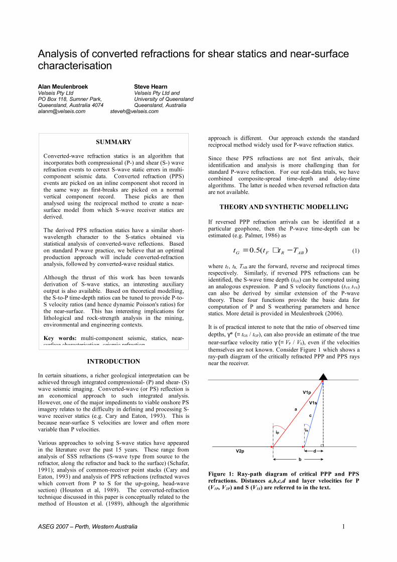
It is of practical interest to note that the ratio of observed time depths, γ* (= tGS / tGP), can also provide an estimate of the true near-surface velocity ratio γ (= VP / VS), even if the velocities themselves are not known. Consider Figure 1 which shows a ray-path diagram of the critically refracted PPP and PPS rays near the receiver.
ip is
a
c
d
b
V1p
V1s
V2p
Figure 1: Ray-path diagram of critical PPP and PPS refractions. Distances a,b,c,d and layer velocities for P (V1P, V2P) and S (V1S) are referred to in the text.
ASEG 2007 – Perth, Western Australia 1
SUMMARY
Converted-wave refraction statics is an algorithm that incorporates both compressional (P-) and shear (S-) wave refraction events to correct S-wave static errors in multi-component seismic data. Converted refraction (PPS) events are picked on an inline component shot record in the same way as first-breaks are picked on a normal vertical component record. These picks are then analysed using the reciprocal method to create a near-surface model from which S-wave receiver statics are derived.
The derived PPS refraction statics have a similar short-wavelength character to the S-statics obtained via statistical analysis of converted-wave reflections. Based on standard P-wave practice, we believe that an optimal production approach will include converted-refraction analysis, followed by converted-wave residual statics.
Although the thrust of this work has been towards derivation of S-wave statics, an interesting auxiliary output is also available. Based on theoretical modelling, the S-to-P time-depth ratios can be tuned to provide P-to-S velocity ratios (and hence dynamic Poisson's ratios) for the near-surface. This has interesting implications for lithological and rock-strength analysis in the mining, environmental and engineering contexts.
Key words: multi-component seismic, statics, near-surface characterisation, seismic refraction
Meulenbroek & Hearn Converted-wave Refraction Statics
Based on the P-wave theory of Palmer (1986), it can be shown that the ratio of the S-wave time-depth to P-wave time-depth is:
PP
PS
GP
GS
VbV
a
Vd
Vc
t
t
21
21*
−
−==γ
(2)
where the variables are defined in Figure 1. This expression allows us to deduce the γ* value corresponding to any given γ model. It is therefore feasible to use such synthetic modelling, in reverse, to tune observed γ* estimates to yield the true VP/VS ratio, γ.
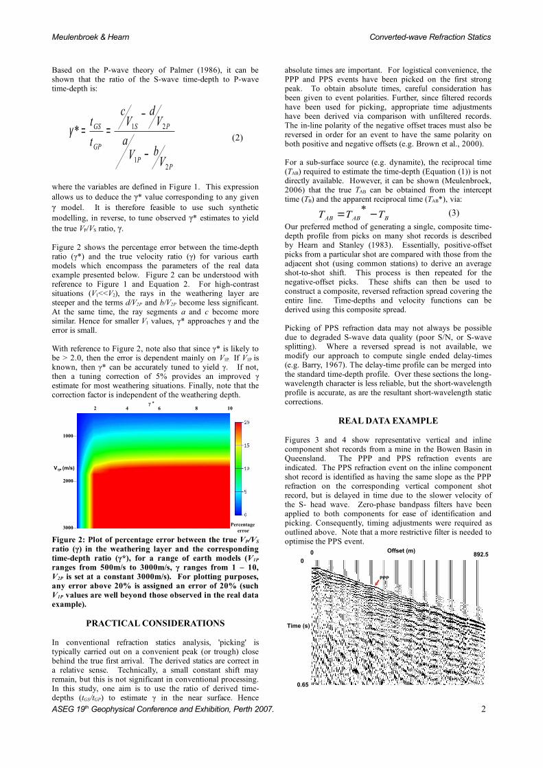
Figure 2 shows the percentage error between the time-depth ratio (γ*) and the true velocity ratio (γ) for various earth models which encompass the parameters of the real data example presented below. Figure 2 can be understood with reference to Figure 1 and Equation 2. For high-contrast situations (V1<<V2), the rays in the weathering layer are steeper and the terms d/V2P and b/V2P become less significant. At the same time, the ray segments a and c become more similar. Hence for smaller V1 values, γ* approaches γ and the error is small.
With reference to Figure 2, note also that since γ* is likely to be > 2.0, then the error is dependent mainly on V1P. If V1P is known, then γ* can be accurately tuned to yield γ. If not, then a tuning correction of 5% provides an improved γ estimate for most weathering situations. Finally, note that the correction factor is independent of the weathering depth.
3000
1000
2000
V1P (m/s)
γ *2 4 6 8 10
Percentage error
Figure 2: Plot of percentage error between the true VP/VS
ratio (γ) in the weathering layer and the corresponding time-depth ratio (γ*), for a range of earth models (V1P
ranges from 500m/s to 3000m/s, γ ranges from 1 – 10, V2P is set at a constant 3000m/s). For plotting purposes, any error above 20% is assigned an error of 20% (such V1P values are well beyond those observed in the real data example).
PRACTICAL CONSIDERATIONS
In conventional refraction statics analysis, 'picking' is typically carried out on a convenient peak (or trough) close behind the true first arrival. The derived statics are correct in a relative sense. Technically, a small constant shift may remain, but this is not significant in conventional processing. In this study, one aim is to use the ratio of derived time-depths (tGS/tGP) to estimate γ in the near surface. Hence
absolute times are important. For logistical convenience, the PPP and PPS events have been picked on the first strong peak. To obtain absolute times, careful consideration has been given to event polarities. Further, since filtered records have been used for picking, appropriate time adjustments have been derived via comparison with unfiltered records. The in-line polarity of the negative offset traces must also be reversed in order for an event to have the same polarity on both positive and negative offsets (e.g. Brown et al., 2000).
For a sub-surface source (e.g. dynamite), the reciprocal time (TAB) required to estimate the time-depth (Equation (1)) is not directly available. However, it can be shown (Meulenbroek, 2006) that the true TAB can be obtained from the intercept time (TB) and the apparent reciprocal time (TAB*), via:
BABAB TTT −= * (3)
Our preferred method of generating a single, composite time-depth profile from picks on many shot records is described by Hearn and Stanley (1983). Essentially, positive-offset picks from a particular shot are compared with those from the adjacent shot (using common stations) to derive an average shot-to-shot shift. This process is then repeated for the negative-offset picks. These shifts can then be used to construct a composite, reversed refraction spread covering the entire line. Time-depths and velocity functions can be derived using this composite spread.
Picking of PPS refraction data may not always be possible due to degraded S-wave data quality (poor S/N, or S-wave splitting). Where a reversed spread is not available, we modify our approach to compute single ended delay-times (e.g. Barry, 1967). The delay-time profile can be merged into the standard time-depth profile. Over these sections the long-wavelength character is less reliable, but the short-wavelength profile is accurate, as are the resultant short-wavelength static corrections.
REAL DATA EXAMPLE
Figures 3 and 4 show representative vertical and inline component shot records from a mine in the Bowen Basin in Queensland. The PPP and PPS refraction events are indicated. The PPS refraction event on the inline component shot record is identified as having the same slope as the PPP refraction on the corresponding vertical component shot record, but is delayed in time due to the slower velocity of the S- head wave. Zero-phase bandpass filters have been applied to both components for ease of identification and picking. Consequently, timing adjustments were required as outlined above. Note that a more restrictive filter is needed to optimise the PPS event.
Time (s)
0
0.65
Offset (m)0 892.5
PPP
ASEG 19th Geophysical Conference and Exhibition, Perth 2007. 2
Meulenbroek & Hearn Converted-wave Refraction Statics
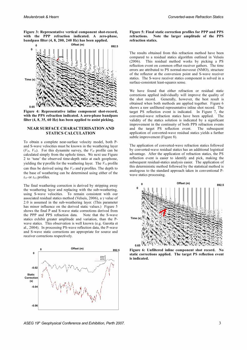
Figure 3: Representative vertical component shot-record, with the PPP refraction indicated. A zero-phase, bandpass filter (4, 8, 200, 240 Hz) has been applied.
Offset (m)0 892.5
Time (s)
0
0.65
PPS
Figure 4: Representative inline component shot-record, with the PPS refraction indicated. A zero-phase bandpass filter (4, 8, 35, 60 Hz) has been applied to assist picking.
NEAR SURFACE CHARACTERISATION AND STATICS CALCULATION
To obtain a complete near-surface velocity model, both P- and S-wave velocities must be known in the weathering layer (V1P, V1S). For this dynamite survey, the V1P profile can be calculated simply from the uphole times. We next use Figure 2 to ‘tune’ the observed time-depth ratio at each geophone, yielding the γ profile for the weathering layer. The V1S profile can thus be derived using the V1P and γ profiles. The depth to the base of weathering can be determined using either of the tGP or tGS profiles.
The final weathering correction is derived by stripping away the weathering layer and replacing with the sub-weathering, using S-wave velocities. To remain consistent with our associated residual statics method (Velseis, 2006), a γ value of 2.0 is assumed in the sub-weathering layer. (This parameter has minor influence on the derived static values.) Figure 5 shows the final P and S-wave static corrections derived from the PPP and PPS refraction data. Note that the S-wave statics exhibit greater amplitude and variation, than the P-wave statics. This observation is well known (e.g. Garotta et al., 2004). In processing PS-wave reflection data, the P-wave and S-wave static corrections are appropriate for source and receiver corrections respectively.
Offset (m)0 892.5
Static Correction
(s)
0
-0.02
-0.04
-0.06
Figure 5: Final static correction profiles for PPP and PPS refractions. Note the larger amplitude of the PPS refraction statics.
The results obtained from this refraction method have been compared to a residual statics algorithm outlined in Velseis (2006). This residual method works by picking a PS reflection event on common offset receiver gathers. The time errors are attributed to PS normal-moveout (NMO), structure of the reflector at the conversion point and S-wave receiver statics. The S-wave receiver statics component is solved in a surface-consistent least-squares sense.
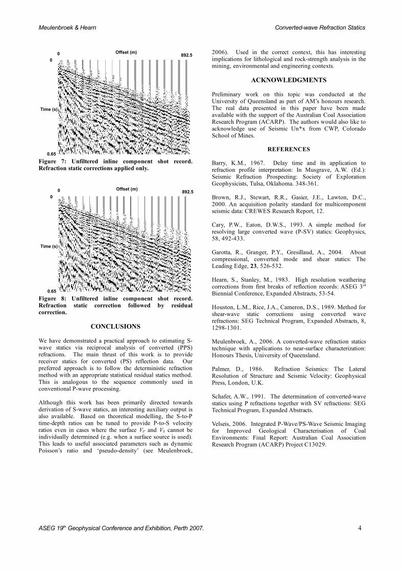
We have found that either refraction or residual static corrections applied individually will improve the quality of the shot record. Generally, however, the best result is obtained when both methods are applied together. Figure 6 shows a raw unfiltered representative inline shot record. The target PS reflection event is indicated. In Figure 7, the converted-wave refraction statics have been applied. The validity of the statics solution is indicated by a significant improvement in the continuity of both PPS refraction events and the target PS reflection event. The subsequent application of converted-wave residual statics yields a further subtle improvement (Figure 8).
The application of converted-wave refraction statics followed by converted-wave residual statics has an additional logistical advantage. After the application of refraction statics, the PS reflection event is easier to identify and pick, making the subsequent residual-statics analysis easier. The application of this deterministic method followed by the statistical method is analogous to the standard approach taken in conventional P-wave statics processing.
Offset (m)0 892.5
Time (s)
0
0.65
Figure 6: Unfiltered inline component shot record. No static corrections applied. The target PS reflection event is indicated.
ASEG 19th Geophysical Conference and Exhibition, Perth 2007. 3
Meulenbroek & Hearn Converted-wave Refraction Statics
Offset (m)0 892.5
Time (s)
0
0.65
Figure 7: Unfiltered inline component shot record. Refraction static corrections applied only.
Offset (m)0 892.50
Time (s)
0.65
Figure 8: Unfiltered inline component shot record. Refraction static correction followed by residual correction.
CONCLUSIONS
We have demonstrated a practical approach to estimating S-wave statics via reciprocal analysis of converted (PPS) refractions. The main thrust of this work is to provide receiver statics for converted (PS) reflection data. Our preferred approach is to follow the deterministic refraction method with an appropriate statistical residual statics method. This is analogous to the sequence commonly used in conventional P-wave processing.
Although this work has been primarily directed towards derivation of S-wave statics, an interesting auxiliary output is also available. Based on theoretical modelling, the S-to-P time-depth ratios can be tuned to provide P-to-S velocity ratios even in cases where the surface VP and VS cannot be individually determined (e.g. when a surface source is used). This leads to useful associated parameters such as dynamic Poisson’s ratio and ‘pseudo-density’ (see Meulenbroek,
2006). Used in the correct context, this has interesting implications for lithological and rock-strength analysis in the mining, environmental and engineering contexts.
ACKNOWLEDGMENTS
Preliminary work on this topic was conducted at the University of Queensland as part of AM’s honours research. The real data presented in this paper have been made available with the support of the Australian Coal Association Research Program (ACARP). The authors would also like to acknowledge use of Seismic Un*x from CWP, Colorado School of Mines.
REFERENCES
Barry, K.M., 1967. Delay time and its application to refraction profile interpretation: In Musgrave, A.W. (Ed.): Seismic Refraction Prospecting: Society of Exploration Geophysicists, Tulsa, Oklahoma. 348-361.
Brown, R.J., Stewart, R.R., Gasier, J.E., Lawton, D.C., 2000. An acquisition polarity standard for multicomponent seismic data: CREWES Research Report, 12.
Cary, P.W., Eaton, D.W.S., 1993. A simple method for resolving large converted wave (P-SV) statics: Geophysics, 58, 492-433.
Garotta, R., Granger, P.Y., Gresillaud, A., 2004. About compressional, converted mode and shear statics: The Leading Edge, 23, 526-532.
Hearn, S., Stanley, M., 1983. High resolution weathering corrections from first breaks of reflection records: ASEG 3rd
Biennial Conference, Expanded Abstracts, 53-54.
Houston, L.M., Rice, J.A., Cameron, D.S., 1989. Method for shear-wave static corrections using converted wave refractions: SEG Technical Program, Expanded Abstracts, 8, 1298-1301.
Meulenbroek, A., 2006. A converted-wave refraction statics technique with applications to near-surface characterization: Honours Thesis, University of Queensland.
Palmer, D., 1986. Refraction Seismics: The Lateral Resolution of Structure and Seismic Velocity: Geophysical Press, London, U.K.
Schafer, A.W., 1991. The determination of converted-wave statics using P refractions together with SV refractions: SEG Technical Program, Expanded Abstracts.
Velseis, 2006. Integrated P-Wave/PS-Wave Seismic Imaging for Improved Geological Characterisation of Coal Environments: Final Report: Australian Coal Association Research Program (ACARP) Project C13029.
ASEG 19th Geophysical Conference and Exhibition, Perth 2007. 4