Embed Size (px)
Citation preview
General rights Copyright and moral rights for the publications made accessible in the public portal are retained by the authors and/or other copyright owners and it is a condition of accessing publications that users recognise and abide by the legal requirements associated with these rights.
• Users may download and print one copy of any publication from the public portal for the purpose of private study or research. • You may not further distribute the material or use it for any profit-making activity or commercial gain • You may freely distribute the URL identifying the publication in the public portal
If you believe that this document breaches copyright please contact us providing details, and we will remove access to the work immediately and investigate your claim.
Downloaded from orbit.dtu.dk on: Jul 01, 2018
Analysis of DC/DC Converter Efficiency for Energy Storage System Based onBidirectional Fuel Cells
Pittini, Riccardo; Zhang, Zhe; Andersen, Michael A. E.
Published in:Proceedings of the 2013 4th IEEE PES Innovative Smart Grid Technologies Europe
Publication date:2013
Link back to DTU Orbit
Citation (APA):Pittini, R., Zhang, Z., & Andersen, M. A. E. (2013). Analysis of DC/DC Converter Efficiency for Energy StorageSystem Based on Bidirectional Fuel Cells. In Proceedings of the 2013 4th IEEE PES Innovative Smart GridTechnologies Europe IEEE.

Analysis of DC/DC Converter Efficiency for Energy
Storage System Based on Bidirectional Fuel Cells
Riccardo Pittini, Zhe Zhang and Michael A.E. Andersen
Technical University of Denmark Dept. of Electrical Engineering
Oersteds Plads 349
Kgs. Lyngby, Denmark
[email protected], [email protected], [email protected]
Abstract—Renewable energy sources are fluctuating depending
on the availability of the energy source. For this reason, energy
storage is becoming more important and bidirectional fuel cells
represent an attractive technology. Fuel cells require high-
current low-voltage dc-dc or dc-ac converters as power interface
to the grid. In power electronics, the converter efficiency is
characterized at fixed operating voltage for various output
power. This type of characterization is not suitable for fuel cells,
since as the power from the fuel cell increases, the cell voltage
decreases. This paper analyses how the fuel cell I-V
characteristics influences the power electronics converter
efficiency and their consequence on the overall system. A load-
dependent efficiency curve is presented based on experimental
results from a 6 kW dc-dc converter prototype including the
most suitable control strategy which maximizes the dc-dc
conversion efficiency.
Index Terms—Fuel cells, Energy storage, Smart grids, Dc-dc
power converters, Energy efficiency.
I. INTRODUCTION
Renewable energy sources are expected to play and important role in the future energy market. However, large scale integration of dynamic renewable energy sources introduces new stress on the old electric grid. Most of the renewable sources are unpredictable (e.g. wind, solar and tidal energy) leading to an increasing need for sustainable grid-tie energy storage. Bidirectional fuel cells, often referred as regenerative fuel cells (RFCs), represent an attractive technology capable of storing energy with high energy density since, electricity is stored as a fuel [1]. Conventional fuel cells are based on polymer electrolyte membrane (PEM); these cells are not suitable for bidirectional operation and they are often combined with supercapacitors or batteries for increasing the system performance [2][3].High temperature solid oxide fuel cells /electrolyzer cells (SOFC /SOFC) have been proven to be capable of operating bidirectionally and with high efficiency making this technology particularly interesting for large scale integration of grid-tie energy storage.
One of the main challenges of RFCs is related to the manufacturing and design of the cells. Designing high power
stacks of RFCs is challenging in terms of reliability, long term degradation and fuel /gas-pressure equalization. Moreover, as the number of series stacked cells increases, higher is the probability that the single cell stresses vary since the same current flows through all the cells (series connection) and different degradation rates are expected to be observed. Dc-dc and dc-ac converters are used for power conditioning in order to avoid too large cells stacks and for properly utilizing the stacks at the desired operating point. In an energy storage system based on RFCs the power flows through the dc-ac and dc-dc converters every time energy is produced or stored, Fig. 1. For this reason, the system efficiency is strongly dependent on the power converters efficiency. Having a dedicated dc-dc converter for each cell stack is advantageous in order to allow controlling each cells stack at a different operating point and allowing high system efficiency since each dc-dc converter is optimized for the single RFC stack.
In most of power electronics applications, dc-dc and dc-ac converters efficiency is characterized at different voltage and power levels [4]. This type of characteristic does not take into account the nature of the source which can strongly affect the operating point and efficiency of the converter. In fact the I-V characteristic of the RFC stack determines the dc-dc converter operating points and, therefore, efficiency characteristic. This paper presents the efficiency characteristics of an experimental dc-dc converter for RFCs rated at 6 kW. The dc-dc converter efficiency is discussed in relation to peak and infield efficiencies. The converter prototype is capable of a peak efficiency of 97.8% however, the I-V characteristics of the RFC stack limits its efficiency to 96.8% at best. A new efficiency characterization of dc-dc converter based on I-V characteristics of the RFCs is proposed. Moreover, a comparison of the calculated and experimental efficiency is presented and discussed.
II. SYSTEM TOPOLOGY FOR RENEWABLE ENERGY
STORAGE BASED ON FUEL CELLS
There are several system topologies that would be suitable for grid-tie energy storage systems based on bidirectional fuel cells. The system configuration and system components will
Project sponsored by the Energy Technology Development and
Demonstration Programme (EUDP) “Green Natural Gas”, 2011-2014.
1
978-1-4799-2984-9/13/$31.00 ©2013 IEEE
2013 4th IEEE PES Innovative Smart Grid Technologies Europe (ISGT Europe), October 6-9, Copenhagen

affect the performance and controllability of the system. The case scenario is a 50 kW energy storage system based on SOFC /SOEC cells, Fig. 1. The selected system topology considers a single grid-tie inverter however, for better system performance at low power levels, small paralleled inverters are recommended.
In the analyzed case each cell stack is composed of 50 solid oxide fuel cells /electrolyzer cells (SOFC /SOEC) capable of operating up to 75 V 80 A in SOEC mode and up to 35 V 40 A in SOFC mode (50 cell stack). The maximum continuous power that the cells can handle is about 5-6 kW in SOEC and 1.5 kW in SOFC; higher power and current would reduce the lifetime of the cells stack. The cells stack characteristics represent the minimum requirements for the dc-dc converter design. Each cells stack has its own dc-dc converter in order to have optimal control and monitoring of each cells stack. During high energy production the system is operated in SOEC mode while during low energy production the system operates in SOFC mode. This type of operation mode also reflects the electricity spot price (low spot price when there is a surplus of energy production and vice versa when the energy production is low). An additional energy storage element is added to the system in order to compensate the low dynamic behavior of the SOFC /SOEC cells. This element increases the dynamic response of the system but also increases the system cost.
III. DC/DC CONVERTER: BIDIRECTIONAL ISOLATED FULL
BRIDGE BOOST CONVERTER
The influence of the dc-dc converter efficiency is analyzed based on a developed prototype of an isolated full bridge boost converter (IFBBC [5]), Fig. 2a. This topology proved to be suitable for fuel cell applications achieving very high efficiency up to 98% at low voltage and high current [4]. One of the main drawbacks of the selected topology is its startup problem when the output voltage (inverter side) is lower than the specified minimum voltage [6]. Several solutions have been proposed to solve this issue [7][8] however, the selected system topology is not affected by this issue since the control loop of the grid tie inverter maintains the high voltage bus in the specified range.
The converter is designed according to the RFCs specifications on Table I. The developed converter is characterized by a low voltage side (RFCs interface) of 30-80 V and 0-80 A, while the high voltage side is defined at 700-800 V for a 400 Vrms grid-tie inverter. The converter has a maximum power of ~6 kW limited by the maximum current on the low voltage side and a switching frequency of 40 kHz, Fig. 2b. The developed dc-dc converter prototype is based on fully planar magnetics (Kool Mu material for the boost inductor and R type material for the transformer, both from Magnetics). The power devices on the low voltage side are Si MOSFETs (IPP041N12N3) and on the high voltage side are Si IGBTs (IGW15N120H3) with SiC diodes (C4D15120A) in antiparallel. The converter efficiency is characterized by laboratory measurements at different voltage levels for the RFCs side (30-80 V) and for both power flow directions. The high voltage dc-bus was kept constant at 750 V.
Fig. 1. Overview of the energy storage system based on bidirectional
fuel cells.
TABLE I
SOFC AND SOEC DC-DC CONVERTER SPECIFICATIONS
SOFC SOEC Low Voltage (LV) side 30-50 50-80 [V]
Current (LV) side 40-0 0-80 [A]
High Voltage (HV) side 700-800 700-800 [V]
Power Rating ~1500 ~6000 [W]
(a) (b)
Fig. 2. Developed prototype of the dc-dc converter (a) and switching waveforms (b) at 60 V 40 A on the low voltage side and 750 V on the high
voltage side in SOFC mode. Ch.1(yellow): Vce,IGBT (350 V/div), Ch.2(red): Vds,MOSFET (50 V/div), Ch.3(blue): ILV inductor,AC (10 A/div),
Ch.4(green): IHV,transformer (5 A/div). Time 5µs/div.
Ch.1: Vce,IGBT (350 V/div) Ch.3: ILV inductor,AC (10 A/div)
Ch.4: IHV,transformer (5A/div) Ch.2: VDS,MOSFET (50 V/div)
GRID
2
IV. INFLUENCE OF DC/DC CONVERTER EFFICIENCY ON
SYSTEM PERFORMANCE
In power electronics dc-dc and dc-ac converters efficiency is often characterized as a function of the output power for different input voltage levels [4]. This type of characterization is commonly used for solar inverters, converters for wind power and also for commercial power adapters. The conventional characterization [4] does not take into account the surrounding system around the dc-dc converter and therefore, the impedance of the energy source; the converter efficiency can vary due to different operating conditions depending on the application. As the current from the fuel cell increases, its terminal voltage decreases and the dc-dc converter efficiency is typically reduced. When the fuel cell is operated as an electrolyzer cell, the cells stack terminal voltage increases as the current and the power increase. For this reason two types of converter characterization are presented: a conventional one and a load dependent one that takes into account the nature of the source.
A. Modeling and Simulation Method
The methodology used for the analysis is based on experimental measurements and results. A dc-dc converter was designed and prototyped; its performance in efficiency
terms was characterized based on a conventional efficiency characterization [4]. The RFC parameters and model were extracted from measurements on RFC prototypes. The models were combined in order to obtain an efficiency characterization of the dc-dc converter that includes the source impedance. As a last step, the dc-dc converter efficiency was compared and validated with the calculations performed during the design phase of the dc-dc converter (a MATLAB script was used to perform the calculations and estimate the dc-dc converter efficiency).
B. Efficiency Characterization of the Converter Prototype
The developed converter prototype, Fig. 2a, is characterized for the entire voltage range on the RFCs side (30-80 V). The high voltage side is fixed to 750 V (constant) since it is connected to a dc-ac converter and its control loop maintains the dc-link voltage constant. The power flow direction affects the efficiency. When the power flow is from the low voltage to the high voltage side (SOFC), the power flows through the low voltage MOSFETs and then through the SiC diodes. Vice versa, when the power flow is reversed, on the high voltage side the power flows through the Si IGBTs and on the low voltage side through the MOSFETs (active rectification).
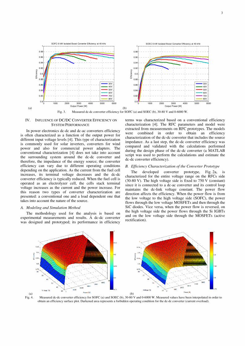
(a) (b) Fig. 4. Measured dc-dc converter efficiency for SOFC (a) and SOEC (b), 30-80 V and 0-6000 W. Measured values have been interpolated in order to
obtain an efficiency surface plot. Darkened area represents a forbidden operating condition for the dc-dc converter (current overload).
(a) (b)
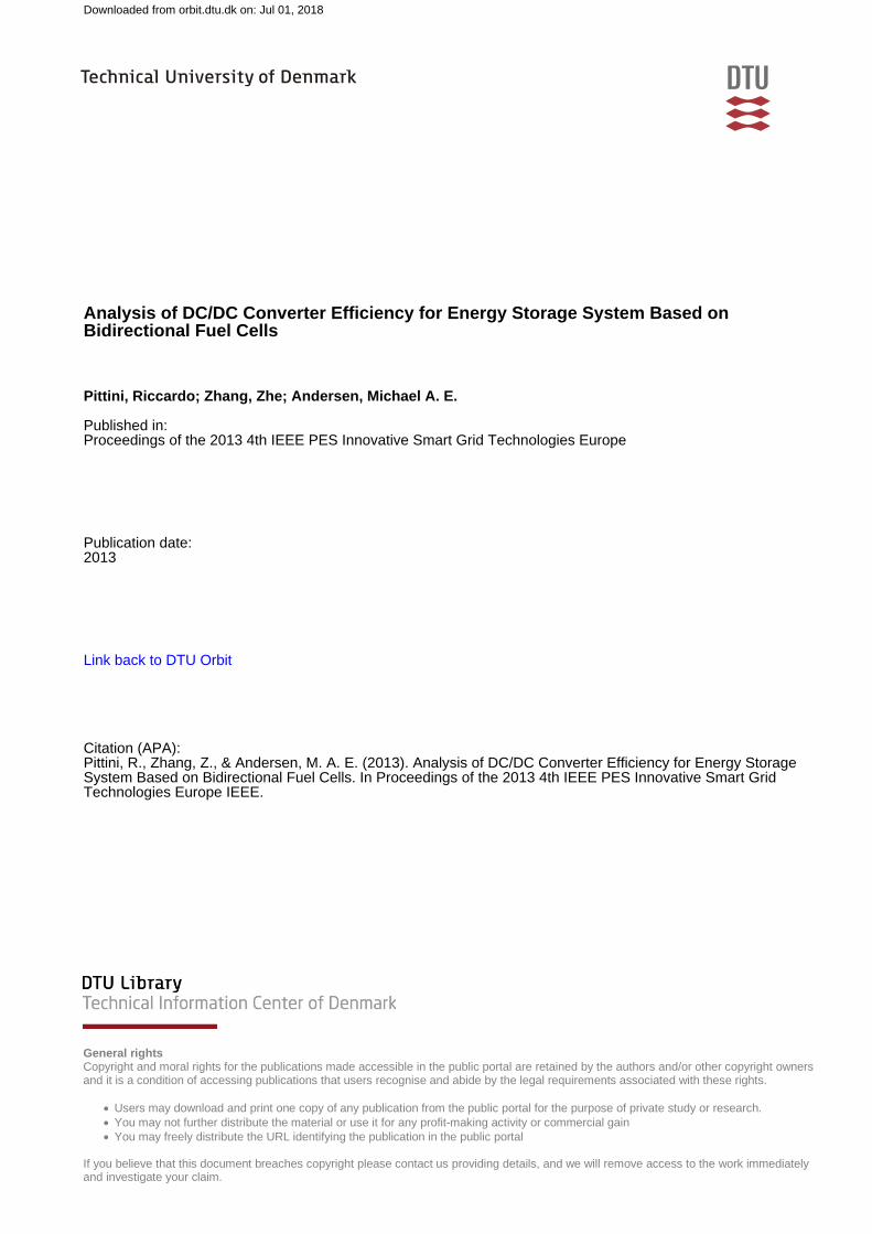
Fig. 3. Measured dc-dc converter efficiency for SOFC (a) and SOEC (b), 30-80 V and 0-6000 W.
0 1000 2000 3000 4000 5000 60000.8
0.82
0.84
0.86
0.88
0.9
0.92
0.94
0.96
0.98
1
Output Power [W]
Eff
icie
ncy
SOFC 6 kW Isolated Boost Converter Efficiency at 40 kHz
30V
40V
50V
60V
70V
80V
0 1000 2000 3000 4000 5000 60000.8
0.82
0.84
0.86
0.88
0.9
0.92
0.94
0.96
0.98
1
Output Power [W]
Eff
icie
ncy
SOEC 6 kW Isolated Boost Converter Efficiency at 40 kHz
30V
40V
50V
60V
70V
80V
3
It is observed that in SOFC mode, Fig. 3a, the converter efficiency is significantly higher than in SOEC mode, Fig. 3b. This is explained by the fact that in SOEC mode the power flows through the IGBTs and these devices generate a significant amount of losses (both conduction and switching losses). As expected, as the voltage on the RFC converter port increases also the converter efficiency increases for the same power level. In this case, the conduction losses decrease as well as the switching losses. At low input voltages the maximum power is limited by the maximum converter current (e.g. Fig. 3a and Fig. 3b 30 V characteristics). With this conventional characterization the converter peak efficiency is about 97.8% in SOFC mode and 96.8% in SOEC mode (including the power required for the gate drivers and the control). The measurements are imported in MATLAB and interpolated for obtaining the complete efficiency characteristic of the converter prototype (Fig. 4a and Fig. 4b).
C. Introducing the RFCs Model into the Efficiency
Characterization
The RFC stack model is introduced to determine the converter efficiency in a real application scenario. Based on the SO-cells I-V characteristic (Fig. 5) it is observed that the electrical behavior of the cells stack is like a voltage source with a series impedance. Since the RFC stack is composed of 50 series connected cells, the series impedance will be the sum of the series impedance of the single cells. The model series
impedance is dominated by the resistive component which is will determine the static I-V characteristic of the RFC stack, Fig. 5. The I-V characteristics of the RFC stack is determined based on the I-V characteristics of single cells; this results in a stack open circuit voltage (OCV, Fig. 5) of 46.3 V and a series resistance (RSO) of 0.3125 Ω. These parameters for the SO-cells stack are obtained from measurements performed on two sample stacks of 10 and 20 cells.
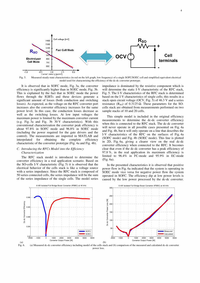
This simple model is included in the original efficiency measurements to determine the dc-dc converter efficiency when this is connected to the RFC stack. The dc-dc converter will never operate in all possible cases presented on Fig. 4a and Fig. 4b, but it will only operate on a line that describes the I-V characteristics of the RFC on the surfaces of Fig. 4a (SOFC mode) and Fig. 4b (SOEC mode). This line is plotted in 2D, Fig. 6a, giving a clearer view on the real dc-dc converter efficiency when connected to the RFC. It becomes clear that even if the dc-dc converter has a peak efficiency of 97.8 %, in the real application its maximum efficiency is limited to 96.4% in FC-mode and 95.9% in EC-mode (Fig. 6a).
In the presented characteristics it is observed that positive power flow in Fig. 6a indicated that the system is operating in SOEC mode vice versa for negative power flow the system operated in SOFC. The efficiency dip at low power levels is caused by the low power processed by the dc-dc converter.
(a) (b) Fig. 6. (a) Measured dc-dc converter efficiency including model of the cells stack and (b) comparison of the measured and calculated dc-dc converter
power loss.
-2000 -1000 0 1000 2000 3000 4000 5000 60000.8
0.84
0.88
0.92
0.96
1
Converter Output Power [W]
Dc-d
c C
onvert
er
Eff
icie
ncy
6 kW Isolated Full Bridge Boost Converter (IFBBC) at 40 kHz
SOFC
SOEC
-2000 -1000 0 1000 2000 3000 4000 5000 60000
50
100
150
200
250
300
Converter Output Power [W]
Dc-d
c C
onvert
er
Pow
er
Loss [
W]
6 kW Isolated Full Bridge Boost Converter (IFBBC) at 40 kHz
Measured
Calculated
Fig. 5. Measured steady-state characteristics (in red on the left graph, low frequency) of a single SOFC/SOEC cell and simplified equivalent electrical
model used for characterizing the efficiency of the dc-dc converter prototype.
4

Even though the overall converter losses are low they represent a large component in the overall power processed by the converter. The new presented characteristics can be used for operating the system around its maximum efficiency and obtaining better system performance.
D. Dc-dc Converter Modeling and Analysis
During the design phase the different components of the converter losses were analyzed in detail. The loss calculations for the magnetic components were based on the generalized Steinmetz equation (GSE [9]) and on Dowel’s equations for taking into account ac-resistances in the inductor and transformer windings, [10]. The switching losses of the MOSFETs (power semiconductors on the RFC stack side) are calculated based on inductive driven commutation [11]. On the high voltage side the losses are calculated based on datasheet values and on switching loss reference measurements [12]. The calculated converter efficiency is compared to the measured one and the dc-dc converter losses are presented on Fig. 6b. It is observed that there is a good match between the two curves in Fig. 6b; this indicated that it is possible to predict the converter efficiency with fair accuracy. A mismatch is observed especially at low power levels where power semiconductor switching losses and inductive component core losses are dominating. This is due to the simplifications used in the models that assume fixed components operating temperature while in a converter prototype temperature varies continuously depending on the converter operating point.
E. High Dc-dc Efficiency System Operation
It is desirable to operate the system at high efficiency in order to have the lowest energy loss in a storage-generation complete cycle. In fact, every storage-generation cycle, energy flows through the dc-dc converter twice having a strong impact on the system performance in both terms of energy efficiency and profitability.
For this reason, the presented system in Fig. 1 has to be operated in order to have the highest number of sub-systems operating close to their maximum efficiency. In each sub-system maximum dc-dc electrical efficiency is defined by the characteristics on Fig. 6a (500-1500 W for SOFC and 1500-5500 W for SOEC). Having wide windows with high dc-dc conversion efficiency increases system controllability and efficiency for various power levels. A flat dc-dc converter efficiency curve represents a good converter design however, this is especially challenging in SOFC mode. Operating each subsystem at low power levels (range 0-500 W) would not result in a good overall system efficiency since the low dc-dc converter efficiency at this point would significantly impact the overall system efficiency.
In this application, the realized converter prototype has peak efficiencies of 95.9% and 96.4% depending on the converter operating point. Since efficiency is one of the major concerns for this application, the replacement of the high voltage power semiconductors with SiC JFETs or SiC MOSFETs would be beneficial in order to further increase the dc-dc converter efficiency. However, this will significantly increase the cost of the dc-dc converter due to the more expensive power devices and gate drivers [13].
CONCLUSIONS
The paper presented an energy storage system for renewable energy applications based on regenerative fuel cells. A high efficiency dc-dc converter prototype was presented and experimentally characterized in efficiency terms. The influence of the dc-dc converter efficiency was discussed and a new dc-dc converter load-dependent efficiency curve was presented. The converter has peak efficiencies of 97.8% and 96.8% depending on the power flow direction. The paper highlight that load-dependent converter efficiency is a key factor for having high system efficiency and the I-V characteristics limits the converter efficiency to 96.4% in fuel cell mode and to 95.9% in electrolyzer cell mode.
REFERENCES
[1] J. D. Maclay, J.Brouwer, G. S.Samuelsen, "Dynamic modeling of hybrid
energy storage systems coupled to photovoltaic generation in residential
applications", 2007 Journal of Power Sources, vol.163, issue 2, pp. 916-
925.
[2] X. Yu, M.R. Starke, L.M. Tolbert and B. Ozpineci; “Fuel cell power
conditioning for electric power applications: a summary” IET Electric
Power Applications, 2007, vol.1, no.5, pp. 643–656, Sept. 2007.
[3] Zhang, Zhe; Pittini, Riccardo; Andersen, Michael A.E.; Thomsen, Ole
C.; “A Review and Design of Power Electronics Converters for Fuel
Cell Hybrid System Applications”, Energy Procedia 2012, Volume 20,
pp. 301-310.
[4] Nymand, M.; Andersen, M. A E, "A new very-high-efficiency R4
converter for high-power fuel cell applications," 2009 International
Conference on Power Electronics and Drive Systems(PEDS), pp.997-
1001, 2-5 Nov. 2009.
[5] Vaisanen, V.; Riipinen, T.; Silventoinen, P.; , "Effects of Switching
Asymmetry on an Isolated Full-Bridge Boost Converter," , IEEE
Transactions on Power Electronics, vol.25, no.8, pp.2033-2044, Aug.
2010.
[6] Mihalic, F.; Hren, A., "Safe start-up procedures of isolated bi-directional
DC-DC converter," 2010 14th International Power Electronics and
Motion Control Conference (EPE/PEMC), pp.T2-67,T2-173, 6-8 Sept.
2010.
[7] Zhu, L.; Kunrong Wang; Lee, F.C.; Jih-Sheng Lai, "New start-up
schemes for isolated full-bridge boost converters," IEEE Transactions
on Power Electronics, vol.18, no.4, pp.946,951, July 2003.
[8] Lindberg-Poulsen, K.; Ouyang, Ziwei; Sen, G.; Andersen, M. A E, "A
new method for start-up of isolated boost converters using magnetic- and
winding-integration", 2012 Twenty-Seventh Annual IEEE Applied Power
Electronics Conference and Exposition (APEC), pp.340,345, 5-9 Feb.
2012.
[9] Ouyang, Ziwei; Thomsen, O.C.; Andersen, M. A E, "Optimal Design
and Tradeoff Analysis of Planar Transformer in High-Power DC–DC
Converters," IEEE Transactions on Industrial Electronics, vol.59, no.7,
pp.2800,2810, July 2012.
[10] P. L. Dowell, "Effects of eddy currents in transformer windings,"
Proceedings of IEEE, vol.113, no.8, August 1966, pp. 1387-1394.
[11] Ziwei Ouyang; Sen, G.; Thomsen, O.C.; Andersen, M. A E, "Analysis
and Design of Fully Integrated Planar Magnetics for Primary–Parallel
Isolated Boost Converter," IEEE Transactions on Industrial Electronics,
vol.60, no.2, pp.494,508, Feb. 2013.
[12] Pittini, R.; D'Arco, S.; Hernes, M.; Petterteig, A.; , "Thermal stress
analysis of IGBT modules in VSCs for PMSG in large offshore Wind
Energy Conversion Systems," Proceedings of the 2011-14th European
Conference on Power Electronics and Applications (EPE 2011), pp.1-
10, Aug. 30 2011-Sept. 1 2011.
[13] Pittini, Riccardo;Zhang, Zhe; Andersen, Michael A.E.; “Switching
Performance Evaluation of Commercial SiC Power Devices (SiC JFET
and SiC MOSFET) in Relation to the Gate Driver Complexity”, ECCE
Asia DownUnder 2013, pp.233,239, 3rd-6th June 2013.
5