Embed Size (px)
Citation preview

Analysis of External Ballistics of a Projectile of Calibre 155 mm
Rui Filipe da Silva Fonte-Boa
Academia Militar & Instituto Superior Técnico, Universidade de Lisboa, Portugal
December 7, 2014
Abstract
The objective of this work was to propose an external geometry for a firefighting projectile named
FIREND. The finite volume code Star − CCM+ R© is used to calculate forces and moments acting on the
projectile. The characteristics of the trajectory are computed using Mathematica R©. The PRODAS V 3 R©
software was used to verify and validate the models implemented.
Initially, the procedure adopted was to create a methodology for an existing ammunition that would
allow to be verified and validated with the available literature. An extensive aerodynamic characterization
has been done through CFD in order to establish the projectile in terms of forces and moments which depend
on the angle of attack and thus feed the script for 6-DOF computation. It was concluded that the locking
strap, the guiding strap and the Coriolis drift were negligible compared to the results obtained.
In the following phase six different geometries were tested, varying the lenght and the nose geometry.
It was defined for this projectile an initial velocity is 100 m/s and the weight 10 kg, concluding that the
total length would be 697.1 mm and hemispherical profile with the capacity to transport 7.5 dm3 inside.
Wind tests were conducted to evaluate the projectile stability in flight. The software and analysis process
developed in this work are available, being a contribution to the project FIREND.
Keywords: Firefighting projectile, projectile geometry, computation of aeroballistic coefficients, six
degree-of-freedom trajectory, dynamic stability analysis.
1 Introduction
The occurrence of forest fires is unavoidable. The
FIREND project arose in 2005 [1] with the ultimate
aim of providing an alternative and additional way
to forest fire fighting, having suffered its last up-
grade in 2013 [2]. The projectile calibre changed to
155 mm. The main reason that justified this change
was to increase the volume of firefighting agent to be
transported inside, which happened to be three times
higher.
This project consists of an artillery shell designed
to fight fires, strengthening the action of the firefight-
ers and Civil Protection. Its performance allows long
distance firefighting in areas of high slope and difficult
access for terrestrial means and in situations with re-
duced visibility, nighttime as well as under adverse
weather conditions.
The FIREND Project is an opportunity to ren-
der the military a new kind of missions in peacetime,
with special interest for the entire population, which
certainly contribute to raising their levels of motiva-
1
tion and to be recognized for their work performed on
behalf of the population.
This study aims to determine a geometry for a
projectile and to ensures flight stability along its tra-
jectory. This requires the use of CFD simulations,
so that the coefficients of force and moment can be
calculated, and also the pseudo-empirical prediction
methods, as is documented in external ballistics liter-
ature. As a final goal we intend to build a software
that couples results from aerodynamic analysis with
the calculation of the flight trajectory using a 6 de-
grees of freedom approach.
2 Description
For external ballistics be understood, it is neces-
sary to take into account several factors, including the
correct nomenclature [3], [4].
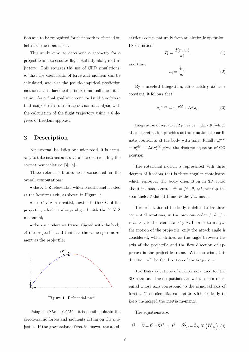
Three reference frames were considered in the
overall computations:
• the X Y Z referential, which is static and located
at the howitzer exit, as shown in Figure 1;
• the x’ y’ z’ referential, located in the CG of the
projectile, which is always aligned with the X Y Z
referential;
• the x y z reference frame, aligned with the body
of the projectile, and that has the same spin move-
ment as the projectile;
Figure 1: Referential used.
Using the Star−CCM+ it is possible obtain the
aerodynamic forces and moments acting on the pro-
jectile. If the gravitational force is known, the accel-
erations comes naturally from an algebraic operation.
By definition:
Fi = d (m vi)dt
(1)
and thus,
ai = dvi
dt(2)
By numerical integration, after setting ∆t as a
constant, it follows that
vinew = vi
old + ∆t.ai (3)
Integration of equation 2 gives vi = dxi/dt, which
after discretization provides us the equation of coordi-
nate position xi of the body with time. Finally xnewi
= xoldi + ∆t.vold
i gives the discrete equation of CG
position.
The rotational motion is represented with three
degrees of freedom that is three angular coordinates
which represent the body orientation in 3D space
about its mass centre: Θ = φ, θ, ψ, with φ the
spin angle, θ the pitch and ψ the yaw angle.
The orientation of the body is defined after three
sequential rotations, in the previous order φ, θ, ψ -
relatively to the referential x’ y’ z’. In order to analyze
the motion of the projectile, only the attack angle is
considered, which defined as the angle between the
axis of the projectile and the flow direction of ap-
proach in the projectile frame. With no wind, this
direction will be the direction of the trajectory.
The Euler equations of motion were used for the
3D rotation. These equations are written on a refer-
ential whose axis correspond to the principal axis of
inertia. The referential can rotate with the body to
keep unchanged the inertia moments.
The equations are:
~M = ~H + ~R−1 ~R ~H or ~M = ~I ~ΩB + ~ΩR X(~I~ΩB
)(4)
2
where
~I =
Ixx 0 0
0 Iyy 0
0 0 Izz
(5)
~Ω = (ωx;ωy;ωz) (6)
The subscripts B and R in Equation 4 represent the
body and the frame, respectively, being ~R the rotation
matrix.
The rotation matrix has 9 free variables, but con-
sidering the symmetry of the matrix, 3 of them are
automatically set. Therefore, the remaining six vari-
ables are used to define three degrees of freedom of
rotational movement in 3D. As such, it will be neces-
sary to reorthonormalize the rotation matrix.
The 6-DOF trajectory was used because it is the
model that best represents the physical phenomenon
of ballistic flight, when we want an overall assessment,
similar to what had been done in 2009 [5], when ef-
fected studies were done to calculate the trajectory
of a 155 mm projectile, resorting to the aid of the
software PRODAS R© to calculate flight behavior.
The use of CFD methodologies to approach a
problem is based on a very specific procedure. During
the pre-processing, it is necessary to define the geom-
etry of the object under study, as well as its domain,
which is divided into discrete cells (the mesh) [6]. The
choice of the mesh to be implemented is very impor-
tant because it will have a decisive role in the solution
of differential equations [7]. The CFD software allows
to calculate the forces and moments at each time and
report to the user [8], which depend on the angle of
attack [9]. It was found that the lift increases with
the angle of attack, as well as the axial force due to
the Magnus effect.
The spin stabilized projectiles for L/D ratio
greater than 7 (L is the length and D the projectile’s
caliber) tends to be unstable unless additional com-
ponents are used to ensure stability [10].
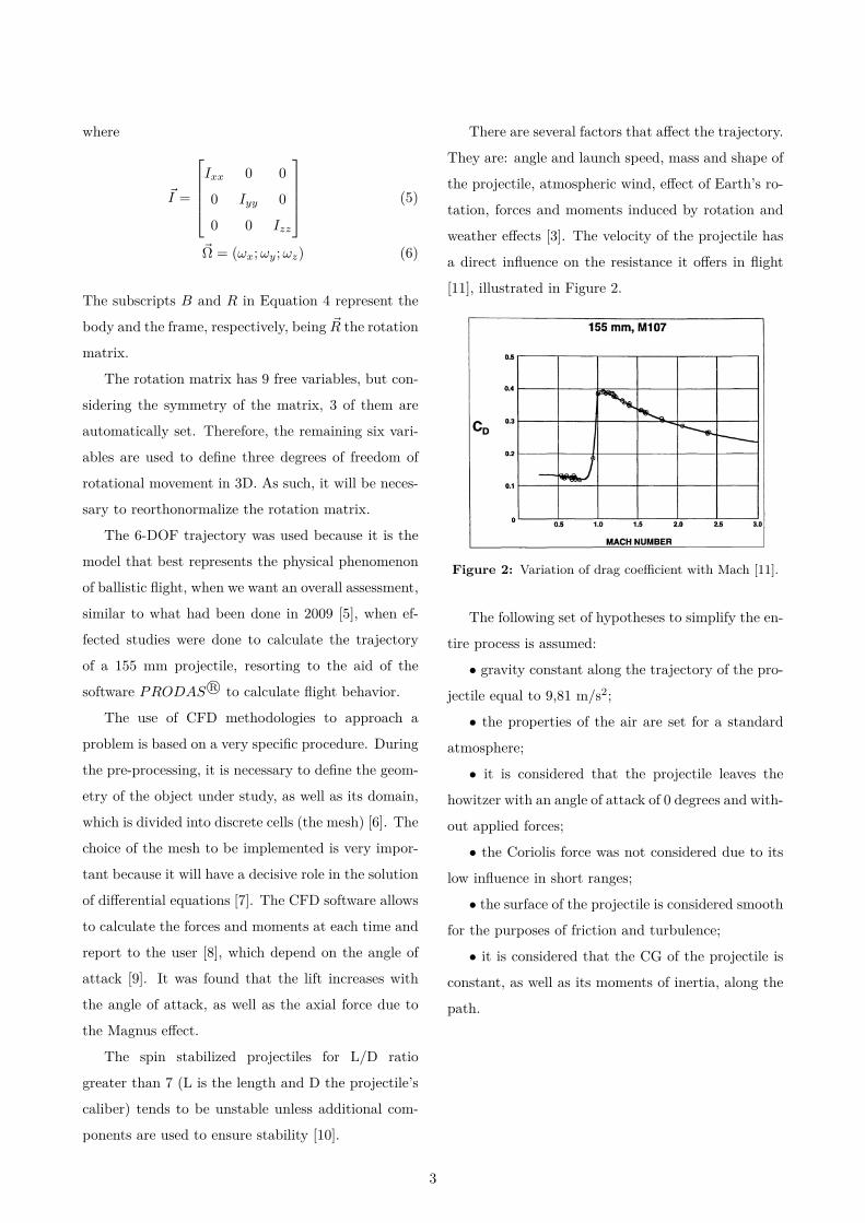
There are several factors that affect the trajectory.
They are: angle and launch speed, mass and shape of
the projectile, atmospheric wind, effect of Earth’s ro-
tation, forces and moments induced by rotation and
weather effects [3]. The velocity of the projectile has
a direct influence on the resistance it offers in flight
[11], illustrated in Figure 2.
Figure 2: Variation of drag coefficient with Mach [11].
The following set of hypotheses to simplify the en-
tire process is assumed:
• gravity constant along the trajectory of the pro-
jectile equal to 9,81 m/s2;
• the properties of the air are set for a standard
atmosphere;
• it is considered that the projectile leaves the
howitzer with an angle of attack of 0 degrees and with-
out applied forces;
• the Coriolis force was not considered due to its
low influence in short ranges;
• the surface of the projectile is considered smooth
for the purposes of friction and turbulence;
• it is considered that the CG of the projectile is
constant, as well as its moments of inertia, along the
path.
3
3 Verification and Validation
The assumptions for the projectile are:
• the howitzer induces a spinning rotation to the
projectile;
• charge 1 is used, therefore subsonic regime.
Another reason was to establish a methodology for
use in optimization processes being the CD approxi-
mately constant in the subsonic regime, having only
that the drag increases with the square of speed and
air density.
The case study for verification and validation was
based on the conventional ammunition M107, illus-
trated in Figure 3, with its main characteristics in
Table 1. These tests were carried out to load 1 (min-
imum charge of gunpowder) which corresponds to a
given rate of translation and rotation.
Figure 3: M107 ammunition geometry.
Table 1: Features with v = 211.8m/s e ω = 344 rad/s.
l (mm) m (kg) CP (mm)* CG (mm)*697.100 43.096 184.04 458.37
∗measured from the nose
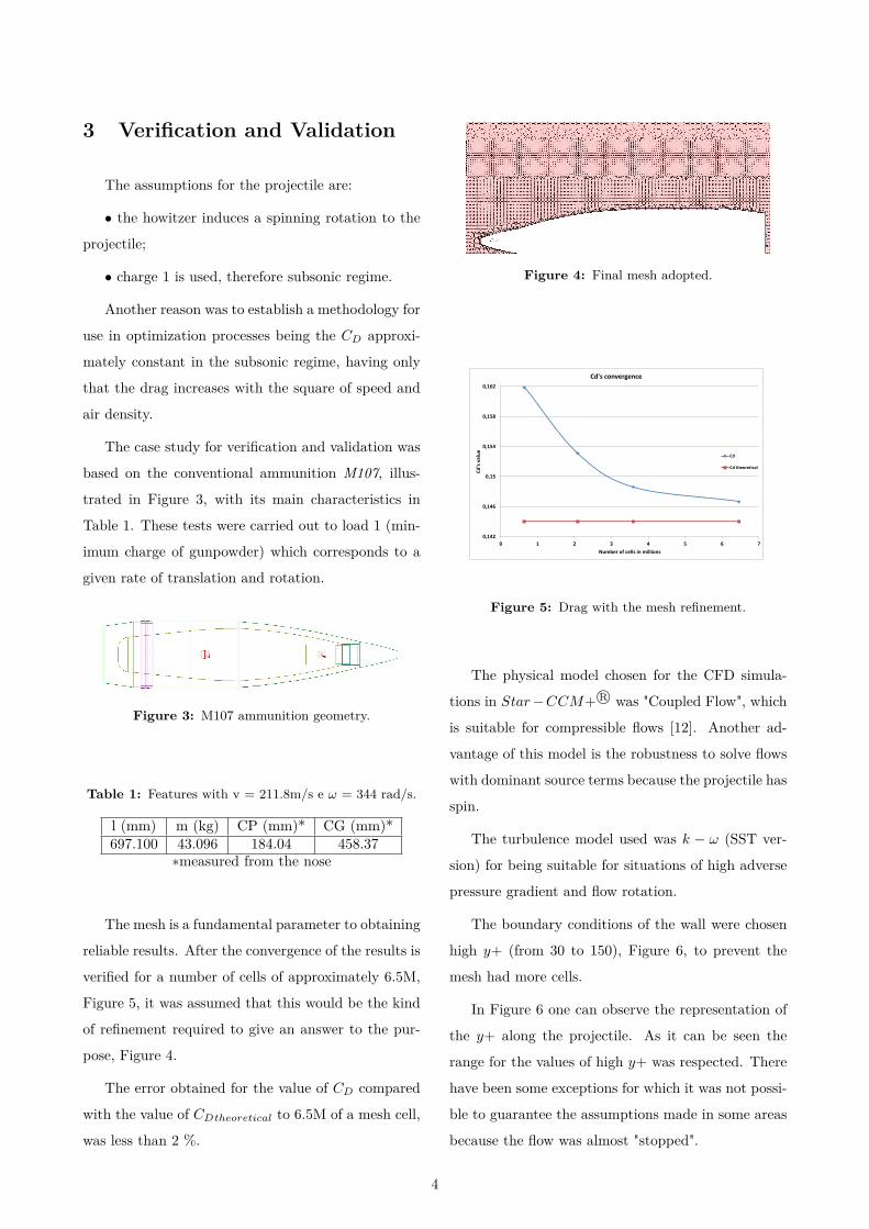
The mesh is a fundamental parameter to obtaining
reliable results. After the convergence of the results is
verified for a number of cells of approximately 6.5M,
Figure 5, it was assumed that this would be the kind
of refinement required to give an answer to the pur-
pose, Figure 4.
The error obtained for the value of CD compared
with the value of CDtheoretical to 6.5M of a mesh cell,
was less than 2 %.
Figure 4: Final mesh adopted.
0,142
0,146
0,15
0,154
0,158
0,162
0 1 2 3 4 5 6 7
Cd
's v
alu
e
Number of cells in millions
Cd's convergence
Cd
Cd theoretical
Figure 5: Drag with the mesh refinement.
The physical model chosen for the CFD simula-
tions in Star−CCM+ R© was "Coupled Flow", which
is suitable for compressible flows [12]. Another ad-
vantage of this model is the robustness to solve flows
with dominant source terms because the projectile has
spin.
The turbulence model used was k − ω (SST ver-
sion) for being suitable for situations of high adverse
pressure gradient and flow rotation.
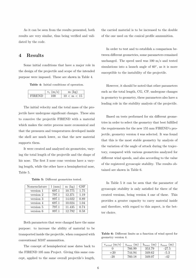
The boundary conditions of the wall were chosen
high y+ (from 30 to 150), Figure 6, to prevent the
mesh had more cells.
In Figure 6 one can observe the representation of
the y+ along the projectile. As it can be seen the
range for the values of high y+ was respected. There
have been some exceptions for which it was not possi-
ble to guarantee the assumptions made in some areas
because the flow was almost "stopped".
4
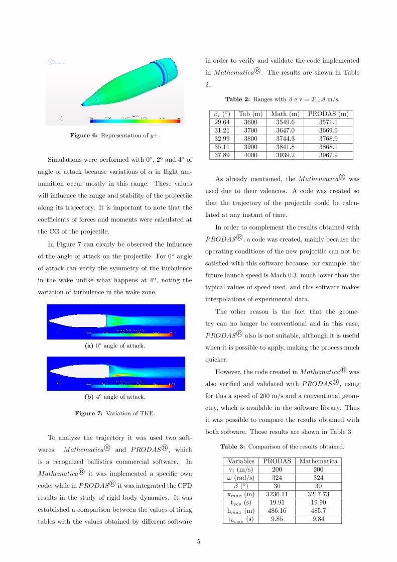
Figure 6: Representation of y+.
Simulations were performed with 0o, 2o and 4o of
angle of attack because variations of α in flight am-
munition occur mostly in this range. These values
will influence the range and stability of the projectile
along its trajectory. It is important to note that the
coefficients of forces and moments were calculated at
the CG of the projectile.
In Figure 7 can clearly be observed the influence
of the angle of attack on the projectile. For 0 angle
of attack can verify the symmetry of the turbulence
in the wake unlike what happens at 4o, noting the
variation of turbulence in the wake zone.
(a) 0o angle of attack.
(b) 4o angle of attack.
Figure 7: Variation of TKE.
To analyze the trajectory it was used two soft-
wares: Mathematica R© and PRODAS R©, which
is a recognized ballistics commercial software. In
Mathematica R© it was implemented a specific own
code, while in PRODAS R© it was integrated the CFD
results in the study of rigid body dynamics. It was
established a comparison between the values of firing
tables with the values obtained by different software
in order to verify and validate the code implemented
in Mathematica R©. The results are shown in Table
2.
Table 2: Ranges with β e v = 211.8 m/s.
βi (o) Tab (m) Math (m) PRODAS (m)29.64 3600 3549.6 3571.131.21 3700 3647.0 3669.932.99 3800 3744.3 3768.935.11 3900 3841.8 3868.137.89 4000 3939.2 3967.9
As already mentioned, the Mathematica R© was
used due to their valencies. A code was created so
that the trajectory of the projectile could be calcu-
lated at any instant of time.
In order to complement the results obtained with
PRODAS R©, a code was created, mainly because the
operating conditions of the new projectile can not be
satisfied with this software because, for example, the
future launch speed is Mach 0.3, much lower than the
typical values of speed used, and this software makes
interpolations of experimental data.
The other reason is the fact that the geome-
try can no longer be conventional and in this case,
PRODAS R© also is not suitable, although it is useful
when it is possible to apply, making the process much
quicker.
However, the code created inMathematica R© was
also verified and validated with PRODAS R©, using
for this a speed of 200 m/s and a conventional geom-
etry, which is available in the software library. Thus
it was possible to compare the results obtained with
both software. Those results are shown in Table 3.
Table 3: Comparison of the results obtained.
Variables PRODAS Mathematicavi (m/s) 200 200ω (rad/s) 324 324β (o) 30 30
xmax (m) 3236.11 3217.73tvoo (s) 19.91 19.90hmax (m) 486.16 485.7thmax
(s) 9.85 9.84
5
As it can be seen from the results presented, both
results are very similar, thus being verified and vali-
dated by the code.
4 Results
Some initial conditions that have a major role in
the design of the projectile and scope of the intended
purpose were imposed. These are shown in Table 4.
Table 4: Initial conditions of operation.
vi (m/s) m (kg)FIREND 100 10 < m < 15
The initial velocity and the total mass of the pro-
jectile have undergone significant changes. These aim
to conceive the projectile FIREND with a material
which makes the entire process more economical and
that the pressures and temperatures developed inside
the shell are much lower, so that the new material
supports them.
It were created and analyzed six geometries, vary-
ing the total length of the projectile and the shape of
his nose. The first 3 nose cone versions have a vary-
ing length, while the other have a hemispherical nose,
Table 5.
Table 5: Different geometries tested.
Nomenclature l (mm) m (kg) GSFversion 1 697.1 10.775 1.75version 2 797.1 12.371 1.19version 3 897.1 14.022 0.89version 4 697.1 10.024 1.04version 5 797.1 11.435 0.74version 6 897.1 12.792 0.58
Both parameters that were changed have the same
purpose: to increase the ability of material to be
transported inside the projectile, when compared with
conventional M107 ammunition.
The concept of hemispherical nose dates back to
the FIREND 105 mm Project. Giving this same con-
cept, applied to the same overall projectile’s length,
the carried material is to be increased to the double
of the one used on the conical profile ammunition.
In order to test and to establish a comparison be-
tween different geometries, some parameters remained
unchanged. The speed used was 100 m/s and tested
simulations into a launch angle of 60, as it is more
susceptible to the instability of the projectile.
However, it should be noted that other parameters
such as the total length, CG, CP, undergone changes
in geometry to geometry, these parameters also have a
leading role in the stability analysis of the projectile.
Based on tests performed for six different geome-
tries in order to select the geometry that best fulfilled
the requirements for the new 155 mm FIREND’s pro-
jectile, geometry version 4 was selected. It was found
that this is the most stable geometry by analysis of
the variation of the angle of attack during the trajec-
tory, compared with various geometries analyzed for
different wind speeds, and also according to the value
of the registered gyroscopic stability. The results ob-
tained are shown in Table 6.
In Table 5 it can be seen that the parameter of
gyroscopic stability is only satisfied for three of the
created versions, being version 4 one of these. This
provides a greater capacity to carry material inside
and therefore, with regard to this aspect, is the bet-
ter choice.
Table 6: Different limits as a function of wind speed forgeometry version 4.
vwind (m/s) xmax (m) hmax (m) zmax (m)0 766.99 353.79 -27.5
+20 744.94 349.62 -5.3-20 760.18 349.07 -42
6
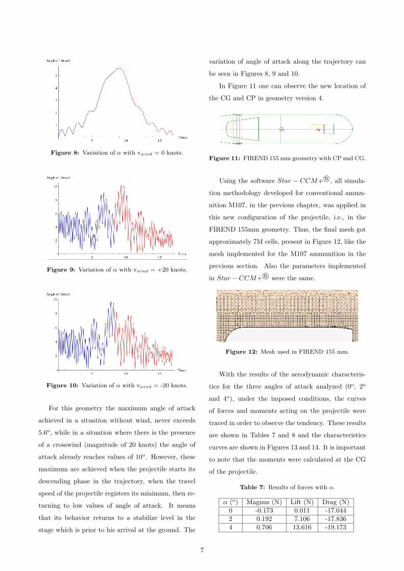
Figure 8: Variation of α with vwind = 0 knots.
Figure 9: Variation of α with vwind = +20 knots.
Figure 10: Variation of α with vwind = -20 knots.
For this geometry the maximum angle of attack
achieved in a situation without wind, never exceeds
5.6o, while in a situation where there is the presence
of a crosswind (magnitude of 20 knots) the angle of
attack already reaches values of 10o. However, these
maximum are achieved when the projectile starts its
descending phase in the trajectory, when the travel
speed of the projectile registers its minimum, then re-
turning to low values of angle of attack. It means
that its behavior returns to a stabilize level in the
stage which is prior to his arrival at the ground. The
variation of angle of attack along the trajectory can
be seen in Figures 8, 9 and 10.
In Figure 11 one can observe the new location of
the CG and CP in geometry version 4.
Figure 11: FIREND 155 mm geometry with CP and CG.
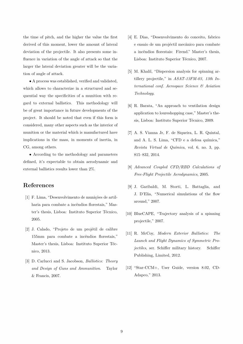
Using the software Star − CCM+ R©, all simula-
tion methodology developed for conventional ammu-
nition M107, in the previous chapter, was applied in
this new configuration of the projectile, i.e., in the
FIREND 155mm geometry. Thus, the final mesh got
approximately 7M cells, present in Figure 12, like the
mesh implemented for the M107 ammunition in the
previous section. Also the parameters implemented
in Star − CCM+ R© were the same.
Figure 12: Mesh used in FIREND 155 mm.
With the results of the aerodynamic characteris-
tics for the three angles of attack analyzed (0o, 2o
and 4o), under the imposed conditions, the curves
of forces and moments acting on the projectile were
traced in order to observe the tendency. These results
are shown in Tables 7 and 8 and the characteristics
curves are shown in Figures 13 and 14. It is important
to note that the moments were calculated at the CG
of the projectile.
Table 7: Results of forces with α.
α (o) Magnus (N) Lift (N) Drag (N)0 -0.173 0.011 -17.0442 0.192 7.106 -17.8364 0.706 13.616 -19.173
7
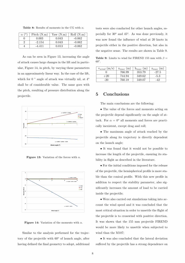
Table 8: Results of moments in the CG with α.
α (o) Pitch (N.m) Yaw (N.m) Roll (N.m)0 0.003 0.043 -0.0622 -2.154 0.043 -0.0624 -4.411 0.013 -0.062
As can be seen in Figure 13, increasing the angle
of attack causes large changes in the lift and in partic-
ular, Figure 14, in pitch, by varying these parameters
in an approximately linear way. In the case of the lift,
which for 0 angle of attack was virtually nil, at 4o
shall be of considerable value. The same goes with
the pitch, resulting of pressure distribution along the
projectile.
y = -0,068x2 - 0,2602x - 17,044
y = -0,0747x2 + 3,7025x
y = 0,0403x2 + 0,0153x
-25
-15
-5
5
15
0 1 2 3 4
Forc
es
(N)
Attack angle (°)
Drag
Lift
Magnus
Figure 13: Variation of the forces with α.
y = -0,0127x2 - 1,0517x
y = -0,009x2 + 0,0393x
y = 5E-06x2 + 3E-05x - 0,0624
-5
-4
-3
-2
-1
0
1
0 1 2 3 4
Mo
me
nts
(N
.m)
Attack angle (°)
Pitch
Yaw
Roll
Figure 14: Variation of the moments with α.
Similar to the analysis performed for the trajec-
tory of the projectile with 60o of launch angle, after
having defined the final geometry to adopt, additional
tests were also conducted for other launch angles, es-
pecially for 30o and 45o. As was done previously, it
was now found the influence of wind at 20 knots in
projectile either in the positive direction, but also in
the negative sense. The results are shown in Table 9.
Table 9: Limits to wind for FIREND 155 mm with β =60o.
vwind (m/s) xmax (m) hmax (m) zmax (m)0 766.99 353.79 -27.5
+20 744.94 349.62 -5.3-20 760.18 349.07 -42
5 Conclusions
The main conclusions are the following:
• The value of the forces and moments acting on
the projectile depend significantly on the angle of at-
tack. For α = 0o all moments and forces are practi-
cally inexistent, except drag and roll;
• The maximum angle of attack reached by the
projectile along its trajectory is directly dependent
on the launch angle;
• It was found that it would not be possible to
increase the length of the projectile, ensuring its sta-
bility in flight as described in the literature.
• For the initial conditions imposed for the release
of the projectile, the hemispherical profile is more sta-
ble than the conical profile. With this new profile in
addition to respect the stability parameter, also sig-
nificantly increases the amount of load to be carried
inside the projectile;
• Were also carried out simulations taking into ac-
count the wind speed and it was concluded that the
most critical situation in order to unsettle the flight of
the projectile is to crosswind with positive direction.
It was shown that the 155 mm projectile FIREND
would be more likely to unsettle when subjected to
wind than the M107;
• It was also concluded that the lateral deviation
suffered by the projectile has a strong dependence on
8
the time of pitch, and the higher the value the first
derived of this moment, lower the amount of lateral
deviation of the projectile. It also presents some in-
fluence in variation of the angle of attack so that the
larger the lateral deviation greater will be the varia-
tion of angle of attack.
• A process was established, verified and validated,
which allows to characterize in a structured and se-
quential way the specificities of a munition with re-
gard to external ballistics. This methodology will
be of great importance in future developments of the
project. It should be noted that even if this form is
considered, many other aspects such as the interior of
munition or the material which is manufactured have
implications in the mass, in moments of inertia, in
CG, among others.
• According to the methodology and parameters
defined, it’s expectable to obtain aerodynamic and
external ballistics results lower than 2%.
References
[1] F. Lima, “Desenvolvimento de munições de artil-
haria para combate a incêndios florestais,” Mas-
ter’s thesis, Lisboa: Instituto Superior Técnico,
2005.
[2] J. Calado, “Projeto de um projétil de calibre
155mm para combate a incêndios florestais,”
Master’s thesis, Lisboa: Instituto Superior Téc-
nico, 2013.
[3] D. Carlucci and S. Jacobson, Ballistics: Theory
and Design of Guns and Ammunition. Taylor
& Francis, 2007.
[4] E. Dias, “Desenvolvimento do conceito, fabrico
e ensaio de um projéctil mecânico para combate
a incêndios florestais: Firend.” Master’s thesis,
Lisboa: Instituto Superior Técnico, 2007.
[5] M. Khalil, “Dispersion analysis for spinning ar-
tillery projectile,” in ASAT-13FM-03, 13th In-
ternational conf. Aerospace Science & Aviation
Technology.
[6] R. Barata, “An approach to ventilation design
application to loureshopping case,” Master’s the-
sis, Lisboa: Instituto Superior Técnico, 2009.
[7] A. S. Vianna Jr, F. de Siqueira, L. R. Quintal,
and A. L. S. Lima, “CFD e a defesa química,”
Revista Virtual de Química, vol. 6, no. 3, pp.
815–832, 2014.
[8] Advanced Coupled CFD/RBD Calculations of
Free-Flight Projectile Aerodynamics, 2005.
[9] J. Garibaldi, M. Storti, L. Battaglia, and
J. D’Elia, “Numerical simulations of the flow
around,” 2007.
[10] BlueCAPE, “Trajectory analysis of a spinning
projectile,” 2007.
[11] R. McCoy, Modern Exterior Ballistics: The
Launch and Flight Dynamics of Symmetric Pro-
jectiles, ser. Schiffer military history. Schiffer
Publishing, Limited, 2012.
[12] “Star-CCM+, User Guide, version 8.02, CD-
Adapco,” 2013.
9