Embed Size (px)
Citation preview
Sandra Kvaternik Goran Turkalj Domagoj Lanc
https://doi.org/10.21278/TOF.41401 ISSN 1333-1124
eISSN 1849-1391
ANALYSIS OF FLEXURE, TORSION AND BUCKLING OF THIN-WALLED FRAMES WITH A FOCUS ON THE JOINT WARPING
BEHAVIOUR
Summary
This paper presents a finite element analysis of flexural-torsional and buckling behaviour of a thin-walled frame with a special focus on the joint warping behaviour. Four different joint types and two different cross-sections are analysed in order to investigate the influence of warping transmission on the overall behaviour of the structure. External loads are assumed to be static and conservative. The material is assumed to be homogenous, isotropic and linear elastic. The analysis is performed using the MSC Nastran shell model consisting of parabolic shell elements. The results obtained in the analysis together with some typical examples are discussed.
Key words: thin-walled frames, joints, warping, flexural-torsional behaviour, buckling
1. Introduction
Weight saving requirements in engineering practice and various industry fields has resulted in widespread use of thin-walled beam-type structures in their stand-alone forms or as stiffeners in shell- or plate-like structures [1-4]. But such structures, especially those composed of open thin-walled profiles, exhibit very complex behaviour due to their susceptibility to instability occurrence and complex flexural-torsional characteristics. Furthermore, the type of structural joints and their warping flexibilities render the analysis far more complicated [5-9].
In St. Venant’s torsion theory of thin-walled beams, the influence of cross-sectional warping is neglected. Although such approach simplifies the analysis, it overlooks the real flexural-torsional behaviour. Several analyses of thin-walled planar frames have shown that torque applied on one member can cause not only flexure, but also torsion in a contiguous unloaded member [9-11]. If the warping transmission is neglected, only flexure would be produced in the second member. But, the fact that warping is ignored causes the pure torsion of the second member to be ignored as well. Orientation and magnitude of torsion transmitted from one member to the other depends on the joint type [12]. Structure deformation consists of two components, St. Venant’s torsion deformation and the warping torsion deformation. Furthermore, flexural-torsional buckling of thin walled beams is a very interesting problem in
TRANSACTIONS OF FAMENA XLI-4 (2017) 1
S. Kvaternik, G. Turkalj, D. Lanc Analysis of Flexure, Torsion and Buckling of Thin-Walled Frames with a Focus on the Joint Warping Behaviour
the field of the structural stability, firstly investigated at the beginning of the 20th century [13, 14] and then by many other researchers [15-19].
This paper presents a numerical analysis of a thin-walled frame with different types of joints subjected to a single-point torque or to uniform distributed load. The aim of this study is to investigate how warping is transmitted in dependence of the joint type from one frame member to the contiguous one and to determine the frame resistance to the buckling load. In order to examine only the warping transmission, additional boundary constraints are introduced at the frame joint. The buckling stability of the frame is analysed in two cases, with and without additional boundary constraints, using the eigenvalue approach. Numerical simulations are carried out using the MSC Nastran shell model consisting of eight-nodded flat elements [20]. External loads are static and conservative. It is assumed that the material is homogeneous and isotropic and that it obeys Hooke's law.
2. Frame geometry
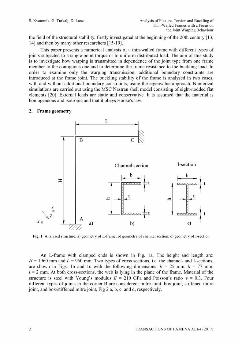
Fig. 1 Analysed structure: a) geometry of L-frame; b) geometry of channel section; c) geometry of I-section
An L-frame with clamped ends is shown in Fig. 1a. The height and length are: H = 1960 mm and L = 960 mm. Two types of cross sections, i.e. the channel- and I-sections, are shown in Figs. 1b and 1c with the following dimensions: b = 25 mm, h = 77 mm, t = 2 mm. At both cross-sections, the web is lying in the plane of the frame. Material of the structure is steel with Young’s modulus E = 210 GPa and Poisson’s ratio = 0.3. Four different types of joints in the corner B are considered: mitre joint, box joint, stiffened mitre joint, and box/stiffened mitre joint, Fig 2 a, b, c, and d, respectively.
2 TRANSACTIONS OF FAMENA XLI-4 (2017)
Analysis of Flexure, Torsion and Buckling of S. Kvaternik, G. Turkalj, D. Lanc Thin-Walled Frames with a Focus on the Joint Warping Behaviour
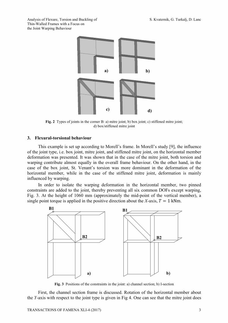
Fig. 2 Types of joints in the corner B: a) mitre joint; b) box joint; c) stiffened mitre joint; d) box/stiffened mitre joint
3. Flexural-torsional behaviour
This example is set up according to Morell’s frame. In Morell’s study [9], the influence of the joint type, i.e. box joint, mitre joint, and stiffened mitre joint, on the horizontal member deformation was presented. It was shown that in the case of the mitre joint, both torsion and warping contribute almost equally in the overall frame behaviour. On the other hand, in the case of the box joint, St. Venant’s torsion was more dominant in the deformation of the horizontal member, while in the case of the stiffened mitre joint, deformation is mainly influenced by warping.
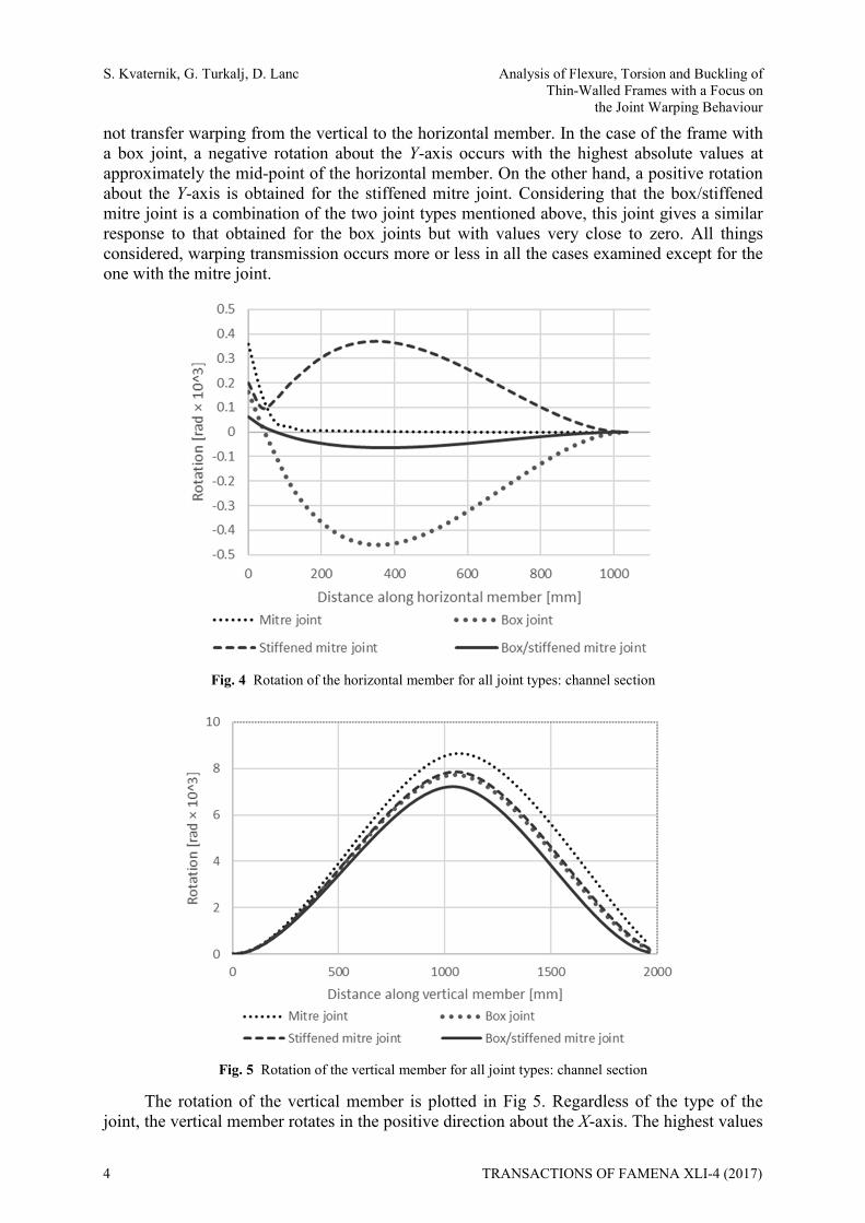
In order to isolate the warping deformation in the horizontal member, two pinned constraints are added to the joint, thereby preventing all six common DOFs except warping, Fig. 3. At the height of 1060 mm (approximately the mid-point of the vertical member), a single point torque is applied in the positive direction about the X-axis, 1kNm.
Fig. 3 Positions of the constraints in the joint: a) channel section; b) I-section
First, the channel section frame is discussed. Rotation of the horizontal member about the Y-axis with respect to the joint type is given in Fig 4. One can see that the mitre joint does
a)
d) c)
b)
TRANSACTIONS OF FAMENA XLI-4 (2017) 3
S. Kvaternik, G. Turkalj, D. Lanc Analysis of Flexure, Torsion and Buckling of Thin-Walled Frames with a Focus on the Joint Warping Behaviour
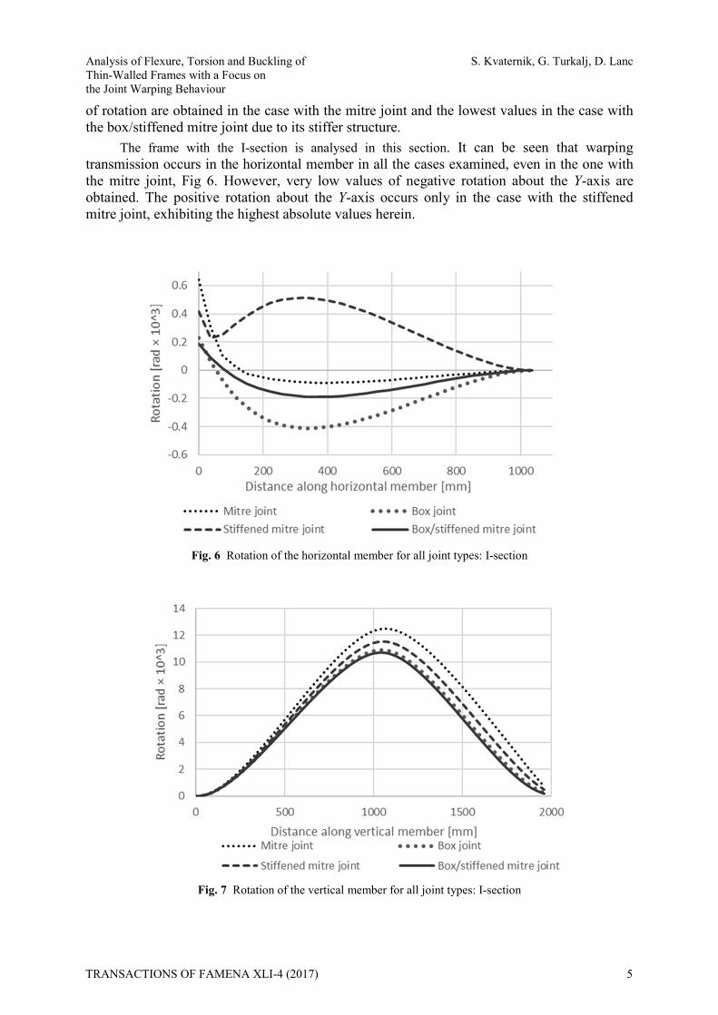
not transfer warping from the vertical to the horizontal member. In the case of the frame with a box joint, a negative rotation about the Y-axis occurs with the highest absolute values at approximately the mid-point of the horizontal member. On the other hand, a positive rotation about the Y-axis is obtained for the stiffened mitre joint. Considering that the box/stiffened mitre joint is a combination of the two joint types mentioned above, this joint gives a similar response to that obtained for the box joints but with values very close to zero. All things considered, warping transmission occurs more or less in all the cases examined except for the one with the mitre joint.
Fig. 4 Rotation of the horizontal member for all joint types: channel section
Fig. 5 Rotation of the vertical member for all joint types: channel section
The rotation of the vertical member is plotted in Fig 5. Regardless of the type of the joint, the vertical member rotates in the positive direction about the X-axis. The highest values
4 TRANSACTIONS OF FAMENA XLI-4 (2017)
Analysis of Flexure, Torsion and Buckling of S. Kvaternik, G. Turkalj, D. Lanc Thin-Walled Frames with a Focus on the Joint Warping Behaviour
of rotation are obtained in the case with the mitre joint and the lowest values in the case with the box/stiffened mitre joint due to its stiffer structure.
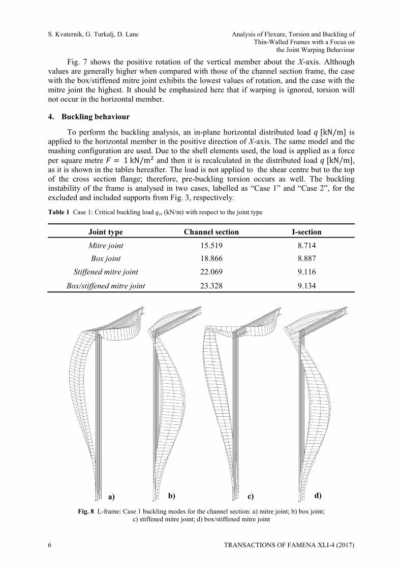
The frame with the I-section is analysed in this section. It can be seen that warping transmission occurs in the horizontal member in all the cases examined, even in the one with the mitre joint, Fig 6. However, very low values of negative rotation about the Y-axis are obtained. The positive rotation about the Y-axis occurs only in the case with the stiffened mitre joint, exhibiting the highest absolute values herein.
Fig. 6 Rotation of the horizontal member for all joint types: I-section
Fig. 7 Rotation of the vertical member for all joint types: I-section
TRANSACTIONS OF FAMENA XLI-4 (2017) 5
S. Kvaternik, G. Turkalj, D. Lanc Analysis of Flexure, Torsion and Buckling of Thin-Walled Frames with a Focus on the Joint Warping Behaviour
Fig. 7 shows the positive rotation of the vertical member about the X-axis. Although values are generally higher when compared with those of the channel section frame, the case with the box/stiffened mitre joint exhibits the lowest values of rotation, and the case with the mitre joint the highest. It should be emphasized here that if warping is ignored, torsion will not occur in the horizontal member.
4. Buckling behaviour
To perform the buckling analysis, an in-plane horizontal distributed load kN/m is applied to the horizontal member in the positive direction of X-axis. The same model and the mashing configuration are used. Due to the shell elements used, the load is applied as a force per square metre 1kN/m and then it is recalculated in the distributed load kN/m , as it is shown in the tables hereafter. The load is not applied to the shear centre but to the top of the cross section flange; therefore, pre-buckling torsion occurs as well. The buckling instability of the frame is analysed in two cases, labelled as “Case 1” and “Case 2”, for the excluded and included supports from Fig. 3, respectively.
Table 1 Case 1: Critical buckling load qcr (kN/m) with respect to the joint type
Fig. 8 L-frame: Case 1 buckling modes for the channel section: a) mitre joint; b) box joint;
c) stiffened mitre joint; d) box/stiffened mitre joint
Joint type Channel section I-section Mitre joint 15.519 8.714 Box joint 18.866 8.887
Stiffened mitre joint 22.069 9.116
Box/stiffened mitre joint 23.328 9.134
b) a) c) d)
6 TRANSACTIONS OF FAMENA XLI-4 (2017)
Analysis of Flexure, Torsion and Buckling of S. Kvaternik, G. Turkalj, D. Lanc Thin-Walled Frames with a Focus on the Joint Warping Behaviour
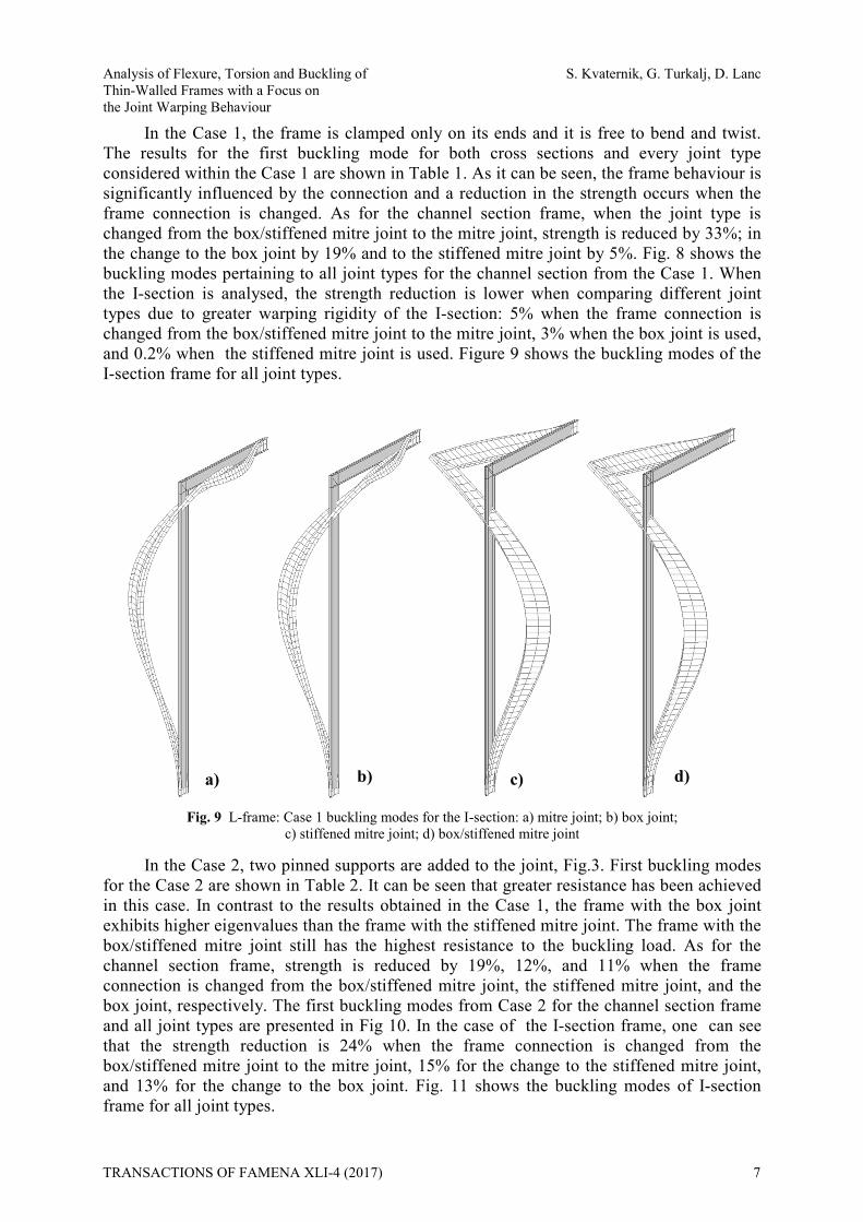
In the Case 1, the frame is clamped only on its ends and it is free to bend and twist. The results for the first buckling mode for both cross sections and every joint type considered within the Case 1 are shown in Table 1. As it can be seen, the frame behaviour is significantly influenced by the connection and a reduction in the strength occurs when the frame connection is changed. As for the channel section frame, when the joint type is changed from the box/stiffened mitre joint to the mitre joint, strength is reduced by 33%; in the change to the box joint by 19% and to the stiffened mitre joint by 5%. Fig. 8 shows the buckling modes pertaining to all joint types for the channel section from the Case 1. When the I-section is analysed, the strength reduction is lower when comparing different joint types due to greater warping rigidity of the I-section: 5% when the frame connection is changed from the box/stiffened mitre joint to the mitre joint, 3% when the box joint is used, and 0.2% when the stiffened mitre joint is used. Figure 9 shows the buckling modes of the I-section frame for all joint types.
Fig. 9 L-frame: Case 1 buckling modes for the I-section: a) mitre joint; b) box joint;
c) stiffened mitre joint; d) box/stiffened mitre joint
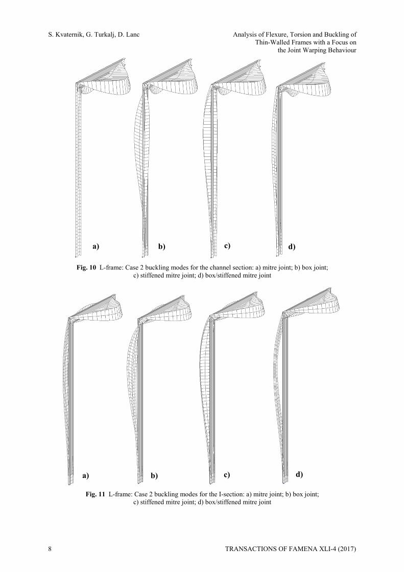
In the Case 2, two pinned supports are added to the joint, Fig.3. First buckling modes for the Case 2 are shown in Table 2. It can be seen that greater resistance has been achieved in this case. In contrast to the results obtained in the Case 1, the frame with the box joint exhibits higher eigenvalues than the frame with the stiffened mitre joint. The frame with the box/stiffened mitre joint still has the highest resistance to the buckling load. As for the channel section frame, strength is reduced by 19%, 12%, and 11% when the frame connection is changed from the box/stiffened mitre joint, the stiffened mitre joint, and the box joint, respectively. The first buckling modes from Case 2 for the channel section frame and all joint types are presented in Fig 10. In the case of the I-section frame, one can see that the strength reduction is 24% when the frame connection is changed from the box/stiffened mitre joint to the mitre joint, 15% for the change to the stiffened mitre joint, and 13% for the change to the box joint. Fig. 11 shows the buckling modes of I-section frame for all joint types.
b) a) c) d)
TRANSACTIONS OF FAMENA XLI-4 (2017) 7
S. Kvaternik, G. Turkalj, D. Lanc Analysis of Flexure, Torsion and Buckling of Thin-Walled Frames with a Focus on the Joint Warping Behaviour
Fig. 10 L-frame: Case 2 buckling modes for the channel section: a) mitre joint; b) box joint;
c) stiffened mitre joint; d) box/stiffened mitre joint
Fig. 11 L-frame: Case 2 buckling modes for the I-section: a) mitre joint; b) box joint;
c) stiffened mitre joint; d) box/stiffened mitre joint
a)
a) b) c) d)
b) c) d)
8 TRANSACTIONS OF FAMENA XLI-4 (2017)
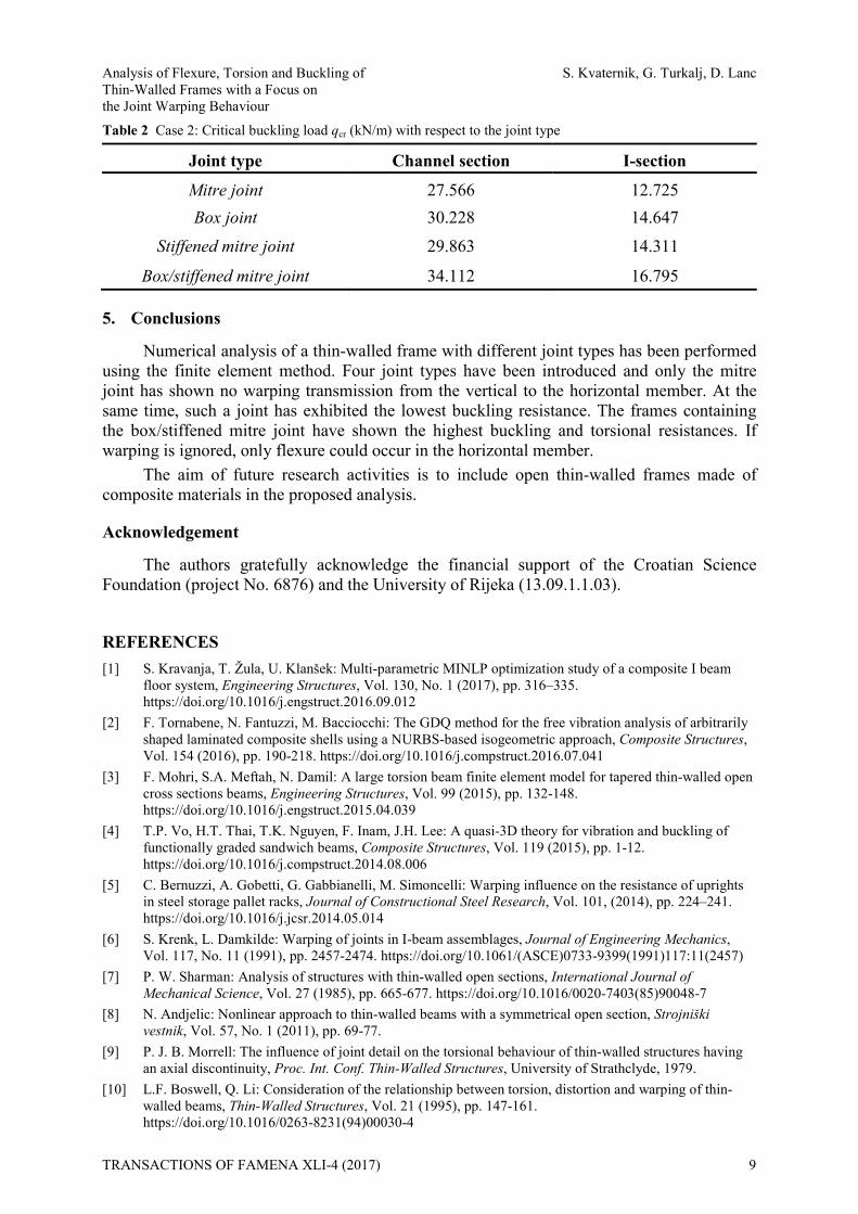
Analysis of Flexure, Torsion and Buckling of S. Kvaternik, G. Turkalj, D. Lanc Thin-Walled Frames with a Focus on the Joint Warping Behaviour Table 2 Case 2: Critical buckling load qcr (kN/m) with respect to the joint type
Joint type Channel section I-section Mitre joint 27.566 12.725 Box joint 30.228 14.647
Stiffened mitre joint 29.863 14.311
Box/stiffened mitre joint 34.112 16.795
5. Conclusions
Numerical analysis of a thin-walled frame with different joint types has been performed using the finite element method. Four joint types have been introduced and only the mitre joint has shown no warping transmission from the vertical to the horizontal member. At the same time, such a joint has exhibited the lowest buckling resistance. The frames containing the box/stiffened mitre joint have shown the highest buckling and torsional resistances. If warping is ignored, only flexure could occur in the horizontal member.
The aim of future research activities is to include open thin-walled frames made of composite materials in the proposed analysis.
Acknowledgement
The authors gratefully acknowledge the financial support of the Croatian Science Foundation (project No. 6876) and the University of Rijeka (13.09.1.1.03).
REFERENCES [1] S. Kravanja, T. Žula, U. Klanšek: Multi-parametric MINLP optimization study of a composite I beam
floor system, Engineering Structures, Vol. 130, No. 1 (2017), pp. 316–335. https://doi.org/10.1016/j.engstruct.2016.09.012
[2] F. Tornabene, N. Fantuzzi, M. Bacciocchi: The GDQ method for the free vibration analysis of arbitrarily shaped laminated composite shells using a NURBS-based isogeometric approach, Composite Structures, Vol. 154 (2016), pp. 190-218. https://doi.org/10.1016/j.compstruct.2016.07.041
[3] F. Mohri, S.A. Meftah, N. Damil: A large torsion beam finite element model for tapered thin-walled open cross sections beams, Engineering Structures, Vol. 99 (2015), pp. 132-148. https://doi.org/10.1016/j.engstruct.2015.04.039
[4] T.P. Vo, H.T. Thai, T.K. Nguyen, F. Inam, J.H. Lee: A quasi-3D theory for vibration and buckling of functionally graded sandwich beams, Composite Structures, Vol. 119 (2015), pp. 1-12. https://doi.org/10.1016/j.compstruct.2014.08.006
[5] C. Bernuzzi, A. Gobetti, G. Gabbianelli, M. Simoncelli: Warping influence on the resistance of uprights in steel storage pallet racks, Journal of Constructional Steel Research, Vol. 101, (2014), pp. 224–241. https://doi.org/10.1016/j.jcsr.2014.05.014
[6] S. Krenk, L. Damkilde: Warping of joints in I-beam assemblages, Journal of Engineering Mechanics, Vol. 117, No. 11 (1991), pp. 2457-2474. https://doi.org/10.1061/(ASCE)0733-9399(1991)117:11(2457)
[7] P. W. Sharman: Analysis of structures with thin-walled open sections, International Journal of Mechanical Science, Vol. 27 (1985), pp. 665-677. https://doi.org/10.1016/0020-7403(85)90048-7
[8] N. Andjelic: Nonlinear approach to thin-walled beams with a symmetrical open section, Strojniški vestnik, Vol. 57, No. 1 (2011), pp. 69-77.
[9] P. J. B. Morrell: The influence of joint detail on the torsional behaviour of thin-walled structures having an axial discontinuity, Proc. Int. Conf. Thin-Walled Structures, University of Strathclyde, 1979.
[10] L.F. Boswell, Q. Li: Consideration of the relationship between torsion, distortion and warping of thin-walled beams, Thin-Walled Structures, Vol. 21 (1995), pp. 147-161. https://doi.org/10.1016/0263-8231(94)00030-4
TRANSACTIONS OF FAMENA XLI-4 (2017) 9
S. Kvaternik, G. Turkalj, D. Lanc Analysis of Flexure, Torsion and Buckling of Thin-Walled Frames with a Focus on the Joint Warping Behaviour [11] V. Z. Vlasov: Thin-walled elastic Bars (in Russian). 2nd ed., Fizmatgiz, Moscow, 1959. [12] A. Masarira: The effect of joints on the stability behaviour of steel frame beams, Journal of
Constructional Steel Research, Vol. 58 (2002), 1375-1390. https://doi.org/10.1016/S0143-974X(02)00017-2
[13] H. Wagner: Verdrehung und Knickung von offenen Profilen, [Translated in NACA TM 807 (1936)], 1929.
[14] R. Kappus: Drillknicken zentrich gedrückter Stäbe mit offenem Profil im elastischen Bereich, [Translated in NACA TM 851 (1938)], 1937.
[15] M. Epstein: Thin-walled beams as directed curves, Acta Mechanica, Vol. 33, No. 3 (1979), pp. 229-242. https://doi.org/10.1007/BF01175918
[16] P. J. B. Morrell, J.R. Riddington, F. A. Ali, H. A. Hamid: Influence of joint detail on the flexural/torsional interaction of thin-walled structures, Thin-Walled Structures, Vol. 24, No. 10 (1996), pp 97-111. https://doi.org/10.1016/0263-8231(95)00048-8
[17] G. Turkalj, J. Brnić: Nonlinear stability analysis of thin-walled frames using UL-ESA formulation, International Journal of Structural Stability and Dynamics, Vol. 4, No. 1 (2004), pp. 45-67. https://doi.org/10.1142/S0219455404001094
[18] G. Turkalj, J. Brnić, D. Lanc: Updated Lagrangian formulation for nonlinear stability analysis of thin-walled frames with semi-rigid connections, International Journal of Structural Stability and Dynamics, Vol. 12, No. 3 (2012), pp 45-67. https://doi.org/10.1142/S0219455412500137
[19] G. Turkalj, J. Brnić, S. Kravanja: A beam-model for large displacement analysis of flexibly connected thin-walled beam-type structures, Thin-Walled Structures, Vol. 19 (2011), pp. 1007-1016. https://doi.org/10.1016/j.tws.2011.03.015
[20] MSC. Nastran, Quick reference guide, MSC Software Corporation, Santa Ana, CA, 2007.
Submitted: 05.5.2017 Accepted: 12.6.2017
Sandra Kvaternik Goran Turkalj Domagoj Lanc University of Rijeka Faculty of Engineering Department of Engineering Mechanics Vukovarska 58 51000 Rijeka Croatia
10 TRANSACTIONS OF FAMENA XLI-4 (2017)