Embed Size (px)
Citation preview
U.P.B. Sci. Bull., Series C, Vol. 77, Iss. 2, 2015 ISSN 2286-3540
ANALYSIS OF PWM STRATEGIES FOR Z-SOURCE CASCADED MULTILEVEL INVERTER FOR
PHOTOVOLTAIC APPLICATIONS
Ramalingam SEYEZHAI*1
MultiLevel Inverters (MLI) are of special interest in the distributed energy sources area because several batteries, fuel cell, solar cell and wind turbine can be connected through MLI to feed a load without voltage balance problems. The disadvantage of MLI is that its output voltage amplitude is limited to DC sources voltage summation. Therefore, a Z-source cascaded multilevel inverter for Photovoltaic (PV) system is proposed in this paper to achieve single energy conversion and boost function. The Z-source network in each module is immune to shoot-through faults when operating at high switching frequency and enhances the system reliability. This paper focuses on phase shifted sinusoidal PWM strategy implemented with simple boost control, maximum boost control and constant boost control for the proposed topology. The performance parameters such as total harmonic distortion (THD), inductor current ripple, capacitor voltage ripple, voltage gain and voltage stress. Simulations of the circuit configuration will be performed in MATLAB/SIMULINK and the results are verified.
Keyword: Multi Level Inverter, Impedance network, Total Harmonic Distortion, Pulse Width Modulation, Shoot-Through
1. Introduction
Among the renewable energy resources, the energy due to the photovoltaic (PV) effect can be considered as the most essential and pre-requisite sustainable resource because of the abundance and sustainability of solar radiant energy. Recently, photovoltaic system is recognized to be in the forefront in renewable electric power generation. It can generate direct current electricity without environmental impact and contamination when exposed to solar radiation. Being a semiconductor device, the PV system is static, quiet, free of moving parts, and has little operation and maintenance costs. Today photovoltaic (PV) systems are typically constructed from ten to a few hundred series parallel connection PV modules connected to a common DC bus inverter. The main drawback of the present grid-connected PV systems is the power losses due to the module mismatch, orientation mismatch, partial shading, and MPPT inefficiencies. The
1 PhD Associate Professor, Department of EEE, SSN College of Engineering, Tamilnadu, India, e-
mail : [email protected]

206 Ramalingam Seyezhai
conventional single DC bus inverter and MPPT methods both cannot solve the above issues due to multiple local peak power points. Therefore, cascaded multilevel inverter will be an ideal choice which can achieve MPPT for each PV module and it reduces the above power loss. But it requires an intermediate DC-DC Converter. Occurring of short circuit can destroy multilevel inverters. To solve these problems, a multilevel inverter based Z-source inverter is proposed in this paper.
A cascaded five level Z-Source inverter is proposed for PV systems and it employs Z network between the DC source and inverter circuitry to achieve boost operation. The output voltage of proposed inverter can be controlled using modulation index and shoot through state. Cascaded Z–Source Multilevel inverter is analysed with third harmonic injection PWM technique.This paper focuses on the implementation of phase shifted sinusoidal PWM with simple boost control, maximum boost control and constant boost control.The performance parameters of the proposed Z-source multilevel inverter such as voltage gain, voltage stress, capacitor ripple, inductor ripple for different modulation indices will be computed .Finally, the feasibility of the proposed inverter is verified through the simulation results.
2. Cascaded Multilevel Z-Source Inverter
The circuit diagram of cascaded Z-Source five-level inverter is shown in Fig. 1.
Fig.1 Circuit diagram of 5-Level cascaded Z-Source MLI
Analysis of PWM strategies for Z-source cascaded Multilevel Inverter for photovoltaic (…) 207
It consists of series single-phase H-bridge inverter units, Z impedances and DC voltage sources. DC sources can be obtained from batteries, fuel cells, solar cells [1]. Each H-bridge Z-Source inverter can generate three different output voltage +Vin, 0, -Vin. Output voltage can be higher than the input voltage when boost factor, B>1. This topology has an extra switching state: shoot through state as compared to cascaded H-bridge inverters. During the shoot-through state, the output voltages of Z networks are zero.
Circuit operation consists of two modes namely shoot -through and non shoot-through states [2,3]. In shoot-through (ST) switching state of Z-Source MLI, upper and lower bridges of the same leg is turned on having the output voltage of zero .During non shoot-through state opposite pairs of legs of both the bridge conducts. In ST state the two inductors are being charged by the capacitors and in non shoot-through state the inductors and input DC source transfer energy to the capacitors and load [3]. Conduction table is shown in Table I.
Table 1 Conduction table
VOLTAGE LEVEL OUTPUT
VOLTAGE ON SWITCHES
Level 2 (non shoot-through)
2Vin S3,S4,S5 ,S6
Level 1 (non shoot-through)
Vin S1,S3,S5 ,S6
Level 1 (shoot-through)
Vin S1,S2, S3, S4, S5, S6
Level 1 (non shoot-through)
Vin S3,S4,S5 ,S7
Level 1 (shoot-through)
Vin S3,S4,S5 ,S6, S7, S8
Level 0 (zero state)
0 (V) S1,S3,S5 ,S7
Level 0 (shoot-through)
0 (V) S1,S2,S3 ,S4,S5,S7
Level 0 (shoot-through)
0 (V) S1,S3,S5 ,S6,S7,S8
Level -1 (non shoot-through)
-Vin S1,S3,S7 ,S8
Level -1 (shoot-through)
-Vin S1, S2, S3, S4, S7,S8
Level -1 (non shoot-through)
-Vin S1,S2,S5 ,S7
Level -1 (shoot-through)
-Vin S1, S2, S5, S6, S7,S8
Level -2 (non shoot-through)
-2Vin S1,S2,S7,S8
208 Ramalingam Seyezhai
3. PWM strategies for Z-source MLI
The modulation control schemes for the multilevel inverter can be divided into two categories, fundamental switching frequency and high switching frequency Pulse Width Modulation (PWM). Further, the high frequency PWM is classified as multilevel carrier-based PWM, selective harmonic elimination and multilevel space vector PWM. The most popular and simple high frequency switching scheme for multilevel inverter is Multi-Carrier-PWM (MCPWM). MCPWM is employed for the proposed topology.
A. Simple Boost Method Simple boost control uses two straight lines to control the shoot-through
states as shown in Fig.2. When the triangular carrier waveform is greater than the upper envelop or lower than the bottom envelope, the circuit turns into shoot-through state otherwise it operates just as traditional carrier-based PWM. The method proposed in this paper is third harmonic injection PWM technique. In this method four phase shifted carrier triangular signals are compared with one modulating signal to produce switching PWM pulses. The reference modulating signal is not sinusoidal but consists of both fundamental component and third harmonic component.
The sinusoidal reference signal can be injected by a third harmonic with a magnitude equal to 25% of the fundamental. This method employs two straight lines that are greater than or less than the peak value of the reference signal to control the shoot-through duty ratio. Inverter operates in shoot-through whenever the triangular carrier signal is higher than the positive straight line or lower than the negative straight line [4-5]. The frequency of the modulating signal is taken as 50Hz.The frequency of the triangular signal can be calculated by Frequency modulation index, mf which is given by,
o
cf f
fm = (1)
where fc is the frequency of the carrier signal and fo is the frequency of sinusoidal and modulating signals. Output voltage depends on the boost factor [6],
TT
VVV
Bsh
ca
pca 21
1)(2
1
1
−=
−−
= (2)
where: Vca - Peak value of the triangular waveform Vp - Amplitude of the constant Tsh - Total shoot-through state period T - Period of switching

Analysis of PWM strategies for Z-source cascaded Multilevel Inverter for photovoltaic (…) 209
The reference and carrier waveform for the proposed third harmonic injection PWM is shown in Fig. 2 followed by the gating pattern shown in Fig. 3. Gating pattern has been generated using MATLAB/SIMULINK.
Fig. 2 Third harmonic injection PWM technique
Fig.3 PWM pulse generation for Third harmonic injection PWM technique
Parameters for Z-Source cascaded MLI using Third harmonic Injection
PWM with simple boost technique are : Boost factor = 1.25, ma=0.8, RL Load where R=50Ω and L=24mH, Input voltage Vdc=75V, Z impedances, L1=L2=L3=L4=L=40mH and C1= C2= C3= C4= 6600µF .Output LC filter having L=30mH and C=150µF.This LC filter can act as an electrical resonator, an electrical analogue of a tuning fork, storing electrical energy oscillating at the circuit's resonant frequency.Figs.4 & 5 show the load voltage waveform without filter and its FFT spectrum. Figs.6& 7 show the load voltage waveform with filter

210 Ramalingam Seyezhai
and its FFT spectrum respectively. Figs.8 &9 show the load current waveform with filter and its FFT spectrum.
Fig.4 Load voltage waveform without filter
Fig.5 FFT spectrum of load voltage waveform without filter
Fig.6 Load voltage waveform with filter

Analysis of PWM strategies for Z-source cascaded Multilevel Inverter for photovoltaic (…) 211
Fig.7 FFT spectrum of load voltage waveform with filter
Fig.8 Load current waveform with filter
Fig. 9 FFT spectrum of load current waveform with filter

212 Ramalingam Seyezhai
B. Maximum boost control with third harmonic injection Maximum boost control with third harmonic injection turns all traditional
zero states into shoot-through state [7-8]. The voltage stress across the switching devices is greatly reduced by fully utilizing the zero states. Turning all zero states into shoot-through state can minimize the voltage stress and this causes a shoot-through duty ratio varying in a line cycle, which causes inductor current ripple. Maximum shoot-through boost factor can be written as,
(3)
where B is boost factor and D is duty ratio which is given by
∏∏−∏
=2
332D (4)
The circuit is in shoot through state when the triangular carrier wave is either greater than the maximum curve of the reference signals or smaller than the minimum of the references [9-10]. The shoot-through duty cycle varies each cycle. The shoot-through state repeats periodically in every п/3 degrees. Fig.10 shows the reference and carrier waveforms for maximum boost control with third harmonic injection PWM technique. The circuit is in shoot through state when the triangular carrier wave is either greater than the maximum curve of the reference signals or smaller than the minimum of the references. The shoot-through duty cycle varies each cycle.
Fig.10 Maximum Boost control with third harmonic injection
DB
211−
=
Analysis of PWM strategies for Z-source cascaded Multilevel Inverter for photovoltaic (…) 213
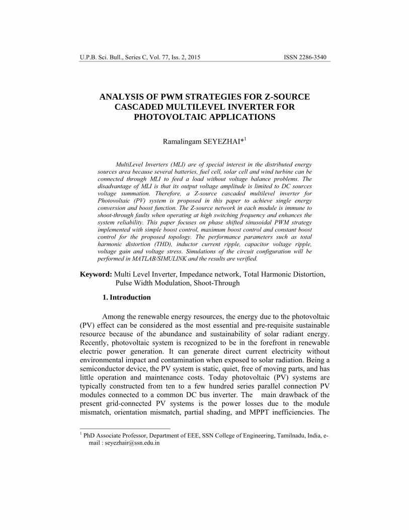
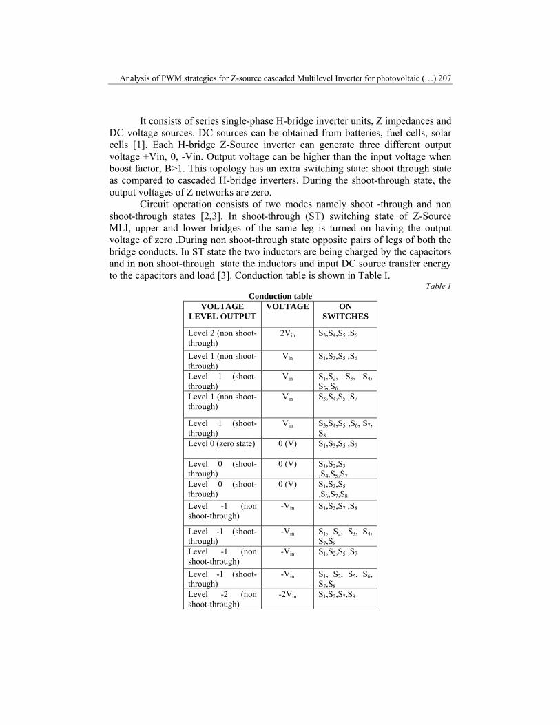
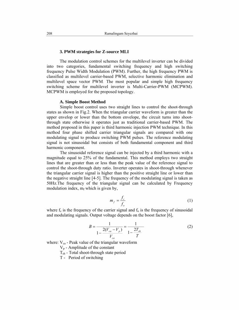
The simulation results for the Z-source MLI with maximum boost control is shown in Figs.11,12 &13.
Fig. 11 Load voltage waveform for maximum boost control with Third Harmonic injection PWM
without filter (Boost factor: 3.09, ma= 0.8, RL Load)
Fig 12. Filtered output voltage waveform for Z-Source MLI
Fig .13 Filtered output current waveform for Z-Source MLI

214 Ramalingam Seyezhai
C. Maximum Constant Boost PWM Method Maximum constant boost control with third harmonic injection achieves
maximum voltage gain by keeping the shoot-through duty ratio constant. Here the basic point is to get the maximum B while keeping it constant all the time which results in low line frequency current ripple through the inductors. The boost factor is determined by the shoot-through duty cycle so the shoot-through duty cycle must be kept the same in order to maintain a constant boost factor[11]. Maximum constant shoot-through boost factor can be written as
(5)
where B is boost factor ,ma is modulation index and D is duty ratio
232 am
D−
=
(6)
The modulation index (ma) for a given boost factor in the maximum constant boost control method can be calculated from equation 3.8.
BBma 3
1+=
(7)
With this method, the inverter can buck and boost the voltage from zero to any desired value smoothly within the limit of the device voltage. Fig.14 shows the reference and carrier waveforms for maximum constant boost with third harmonic injection PWM technique. The sinusoidal reference signal can be injected by a third harmonic with a magnitude equal to 16% of the fundamental.When the carrier triangle wave is greater than the upper shoot-through line or lower than bottom shoot-through line, the inverter is turned to a shoot through state.
Fig.14 Maximum constant boost with Third harmonic injection PWM technique
DB
211−
=
Db
B2111
−
==
Analysis of PWM strategies for Z-source cascaded Multilevel Inverter for photovoltaic (…) 215
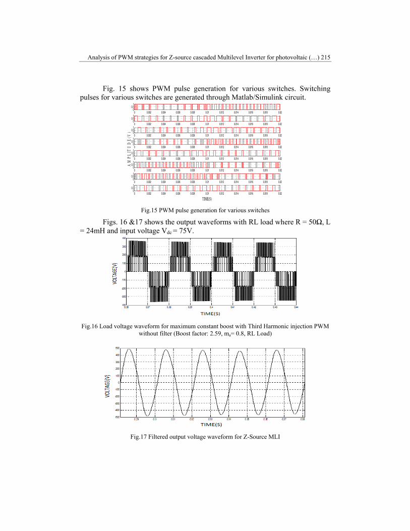
Fig. 15 shows PWM pulse generation for various switches. Switching pulses for various switches are generated through Matlab/Simulink circuit.
Fig.15 PWM pulse generation for various switches
Figs. 16 &17 shows the output waveforms with RL load where R = 50Ω, L = 24mH and input voltage Vdc = 75V.
Fig.16 Load voltage waveform for maximum constant boost with Third Harmonic injection PWM
without filter (Boost factor: 2.59, ma= 0.8, RL Load)
Fig.17 Filtered output voltage waveform for Z-Source MLI
0 0.002 0.004 0.006 0.008 0.01 0.012 0.014 0.016 0.018 0.020
0.51
0 0.002 0.004 0.006 0.008 0.01 0.012 0.014 0.016 0.018 0.020
0.51
0 0.002 0.004 0.006 0.008 0.01 0.012 0.014 0.016 0.018 0.020
0.51
0 0.002 0.004 0.006 0.008 0.01 0.012 0.014 0.016 0.018 0.020
0.51
0 0.002 0.004 0.006 0.008 0.01 0.012 0.014 0.016 0.018 0.020
0.51
0 0.002 0.004 0.006 0.008 0.01 0.012 0.014 0.016 0.018 0.020
0.51
0 0.002 0.004 0.006 0.008 0.01 0.012 0.014 0.016 0.018 0.020
0.51
0 0.002 0.004 0.006 0.008 0.01 0.012 0.014 0.016 0.018 0.020
0.51
TIME(S)
AM
PL
ITU
DE
(V)
216 Ramalingam Seyezhai
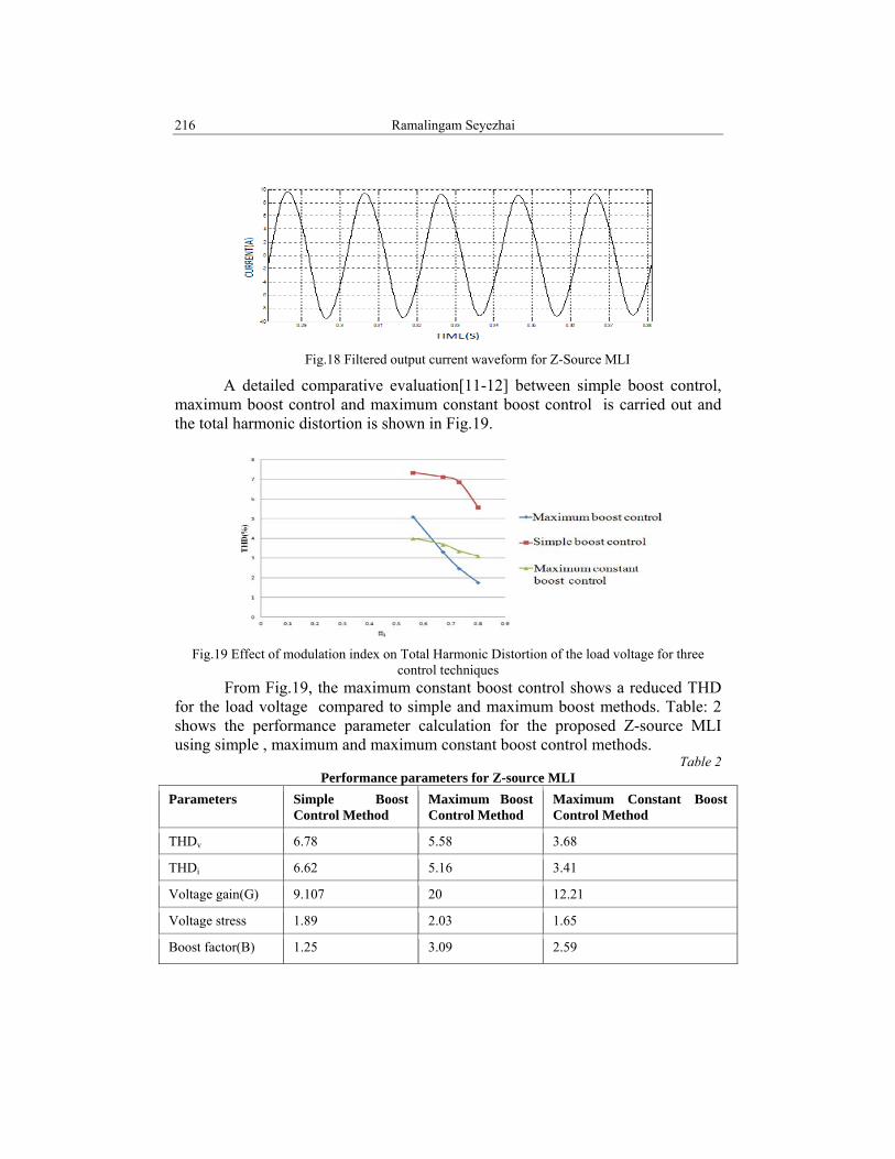
Fig.18 Filtered output current waveform for Z-Source MLI
A detailed comparative evaluation[11-12] between simple boost control, maximum boost control and maximum constant boost control is carried out and the total harmonic distortion is shown in Fig.19.
Fig.19 Effect of modulation index on Total Harmonic Distortion of the load voltage for three
control techniques From Fig.19, the maximum constant boost control shows a reduced THD
for the load voltage compared to simple and maximum boost methods. Table: 2 shows the performance parameter calculation for the proposed Z-source MLI using simple , maximum and maximum constant boost control methods.
Table 2 Performance parameters for Z-source MLI
Parameters Simple Boost Control Method
Maximum Boost Control Method
Maximum Constant Boost Control Method
THDv 6.78 5.58 3.68
THDi 6.62 5.16 3.41
Voltage gain(G) 9.107 20 12.21
Voltage stress 1.89 2.03 1.65
Boost factor(B) 1.25 3.09 2.59

Analysis of PWM strategies for Z-source cascaded Multilevel Inverter for photovoltaic (…) 217
From Table-2, it is inferred that the THD of the load voltage and load current is reduced for the maximum constant boost control method and the voltage stress is also reduced. Hence, maximum constant boost control is preferred for the Z-source cascaded multilevel inverter.
4. Conclusion
This paper has investigated a Z-source cascaded multilevel inverter which
gives a higher output voltage through its Z network. Boost operation is achieved by the shoot through state of Z-Source MLI. Simple boost, maximum boost and maximum constant boost control methods with third harmonic have been investigated for the five-level topology. From the results, it is found that the maximum constant boost control with third harmonic injection provides a reduced THD, higher gain, enhanced fundamental voltage. Therefore, maximum constant boost PWM control is the most suited control which can be employed for the Z-source cascaded MLI for photovoltaic applications.
Acknowledgment The authors wish to thank the AICTE for providing financial support for
carrying out this work and the Management of SSN institutions for providing the computational facilities to carry out this work.
R E F E R E N C E S
[1] M. Reza Banaei and A.R. Dehghanzadeh, “A Z-Source novel based multilevel inverter for renewable sources fed DVR”, IEEE International Conference, Power Quality Conference (PQC), pp.1-6, 2011.
[2] M.R. Mohamad Reza Banaei and A.R. Ali Reza Dehghanzadeh,“DVR based cascaded multilevel Z-source inverter”, IEEE International Conference, Power and Energy (PECon),pp.51-56,2010.
[3] Amitava Das, S.Chowdhury, S.P. Chowdhury and Prof. A. Domijan , Performance analysis of Z-source inverter based ASD system with reduced harmonics”, Power and Energy Society General Meeting - Conversion and Delivery of Electrical Energy in the 21st Century, Pittsburgh,pp.145-151,2010.
[4] F. Z. Peng, “Z-source inverter”, IEEE Trans. Ind. Appl., vol. 39, pp. 504-510, 2005. [5] J. Holtz, “Pulse width modulation – a survey”, IEEE Trans. Ind. Electron., vol. 39, pp. 410-
420, Dec. 2009. [6] Miaosen Shen and F.Z. Peng, “Modulation methods and characteristics of the Z-Source
inverter with small inductance”, Industry Applications Conference, Fortieth IAS Annual Meeting, Vol. 2, pp. 1253 – 1260, 2009.
[7] F. Z. Peng, M. Shen, and Z. Qian, “Maximum boost control of the Z- source inverter,” IEEE Trans. Power Electron., vol. 20, no. 4, pp. 833–838, 2006.
[8] F. Gao, P. C. Loh, D. M. Vilathgamuwa, and F. Blaabjerg, “Performance analysis of random pulse-width modulated z-source inverter with reduced common mode switching,” in Proc. IEEE PESC, pp. 1–7, 2006.
218 Ramalingam Seyezhai
[9] P. C. Loh, D. M. Vilathgamuwa, Y. S. Lai, G. T. Chua and Y. W. Li ,“ Pulse width modulation of Z-source inverters” , IEEE Trans. Power Electronics, Vol. 19, No.3, pp.732-738, 2006.
[10] P. C. Loh, B. Flaabjerg, S. Y. Feng and K.N. Soon, “Pulse-width modulated Z-source neutral-point clamped inverter,” in Proc.IEEE. APEC’05, pp.431–437, 2005.
[11] P. C. Loh, F. Gao, F. Blaabjerg, and S. W. Lim, “Operational analysis and modulation control of three-level Z-source inverters with enhanced output waveform quality, ” IEEE Trans. Power Electron., vol. 24, no. pp. 1767–1775, Jul. 2009.
[12] M.S. Shen, A. Joseph, J. Wang ,F.J. Peng , and D.J Adams, “Comparison of traditional inverters and Z-source inverter”, in Proc. IEEE Power Electron. Spec. Conf., pp. 1692–1698, 2005.