Embed Size (px)
Citation preview
465
Analysis of Rotor Contact for Screw Compressor∗
Hirotaka KAMEYA∗∗, Masakazu AOKI∗∗∗ and Shigekazu NOZAWA∗∗∗∗
A reliability evaluation of meshing rotor surfaces needs contact theory on a micro sizearea. We propose a method to evaluate whether a screw compressor rotor has enough contactfatigue strength. The method is based on analyses of three dimensional curvatures and theHertz contact pressure. At a contact point one of the principal curvatures directs the rotor’ssealing line and this is calculated as the gap distribution. Another perpendicular curvature iscalculated with an approximate arc to the rotor profile. As the contact point is an inflectionpoint, the contact condition is first calculated on each side and then composed. Using ourmethod we found the rotors of a typical screw compressor have enough strength. This isbecause the rotor contact pressure is calculated to be 0.57 times of a contact fatigue strengthof their material.
Key Words: Screw Compressor, Hertz Contact Pressure, Curvature, Helix, Fatigue Strength
1. Introduction
A screw compressor is a kind of positive displace-ment rotary fluid machine. It is used in many industriesas an air compressor, and as a refrigerant compressor forair conditioners. The structure of a screw compressor isshown in Fig. 1. It has a pair of meshing rotors, calledmale and female, with several helical lobes around them.The rotors and their casing bores create enclosed cham-bers in the helical grooves. When the rotors rotate, thechamber volume first gets larger, and then smaller. Gasis sucked into the chamber when the volume is enlarging,and compressed and discharged when the volume is reduc-ing.
If the screw compressor is an oil injected type, oneof the rotors rotates by a motor, and the other is drivenby the first from contact with the lobe surface similar to agear set. Even when the rotors are lubricated by oil, thecontact points should be analyzed to see if their materialsare strong enough. In fact a rotor surface may occasionallybe damaged, especially if the compressor gets overloaded.
∗ Received 5th May, 2004 (No. 04-4069)∗∗ Mechanical Engineering Research Laboratory Hitachi,
Ltd., 502 Kandatsu, Tsuchiura, Ibaraki 300–0013, Japan.E-mail: [email protected]
∗∗∗ Hitachi Industrial Equipment Systems Co., Ltd., 390Shimizumuramatsu, Shizuoka 424–0926, Japan.E-mail: [email protected]
∗∗∗∗ Hitachi Air Conditioning Systems Co., Ltd., 390 Shimizu-muramatsu, Shizuoka 424–0926, Japan.E-mail: nozawa [email protected]
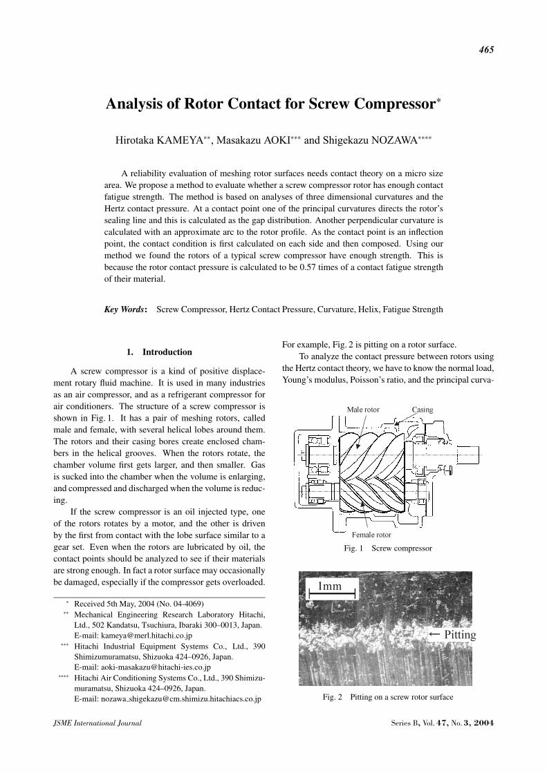
For example, Fig. 2 is pitting on a rotor surface.To analyze the contact pressure between rotors using
the Hertz contact theory, we have to know the normal load,Young’s modulus, Poisson’s ratio, and the principal curva-
Fig. 1 Screw compressor
Fig. 2 Pitting on a screw rotor surface
JSME International Journal Series B, Vol. 47, No. 3, 2004
466
tures(1). It is possible to calculate the contact pressure asan approximate value using the curvature on a transversesection instead of the principal curvatures(2). We, though,have not found papers about three-dimensional curvatureanalysis on screw compressor rotors. Therefore we pro-pose a method of curvature analysis on a micro contactingarea, and estimate contact pressure to be lower than mate-rial strength.
2. Nomenclature
a, b, c, d, e : points on female rotorf, g, h, i, j, k : points on male rotor
Krt : gap varying ratio with rotor rotation [—]L : position on sealing line [mm]N : normal load at contact point [N]n : overlap ratio of rotor lobe [—]
Rp : pitch circle radius [mm]R : rotation radius of contact point [mm]T : transmission torque [N ·m]
X, Y , Z : coordinate of point on profile [mm]σH : Hertz contact pressure (stress) [MPa]θ : angle between rotational tangent and
surface perpendicular [rad]
3. Profile and Sealing Line
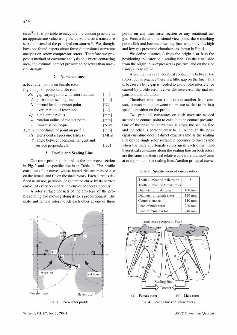
Our rotor profile is defined as the transverse sectionin Fig. 3 and its specification is in Table 1. The profileconstitutes four curves whose boundaries are marked a–eon the female and f–j on the male rotors. Each curve is de-fined as an arc, parabola, or generated curve by its partnercurve. At every boundary, the curves connect smoothly.
A rotor surface consists of the envelope of the pro-file rotating and moving along its axis proportionally. Themale and female rotors touch each other at one or three
Fig. 3 Screw rotor profile
points on any transverse section or any rotational an-gle. From a three-dimensional view point, these touchingpoints link and become a sealing line, which divides highand low gas pressured chambers, as shown in Fig. 4.
We define distance L from the origin c or h as thepositioning indicator on a sealing line. On the e or j sidefrom the origin, L is expressed as positive, and on the a orf side, L is negative.
A sealing line is a theoretical contact line between therotors, but in practice there is a little gap on the line. Thisis because a little gap is needed to avoid rotor interferencecaused by profile error, center distance error, thermal ex-pansion, and vibration.
Therefore when one rotor drives another from con-tact, contact points between rotors are settled to be in aspecific position on the profile.
Two principal curvatures on each rotor are neededaround the contact point to calculate the contact pressure.One of the principal curvatures is along the sealing lineand the other is perpendicular to it. Although the prin-cipal curvature doesn’t direct exactly same as the sealingline on the single rotor surface, it becomes to direct samewhen the male and female rotors mesh each other. Thetheoretical curvatures along the sealing line on both rotorsare the same and their real relative curvature is almost zeroat every point on the sealing line. Another principal curva-
Table 1 Specifications of sample rotors
(a) Female rotor (b) Male rotor
Fig. 4 Sealing lines on screw rotors
Series B, Vol. 47, No. 3, 2004 JSME International Journal
467
ture perpendicular to the sealing line is the largest relativecurvature according to a geometric law.
4. Curvature along Sealing Line
The smallest relative curvature along the sealing lineis calculated as the gap distribution. The distribution sup-poses the gap is first given uniformly, and the male rotordrives the female rotor via surface contact.
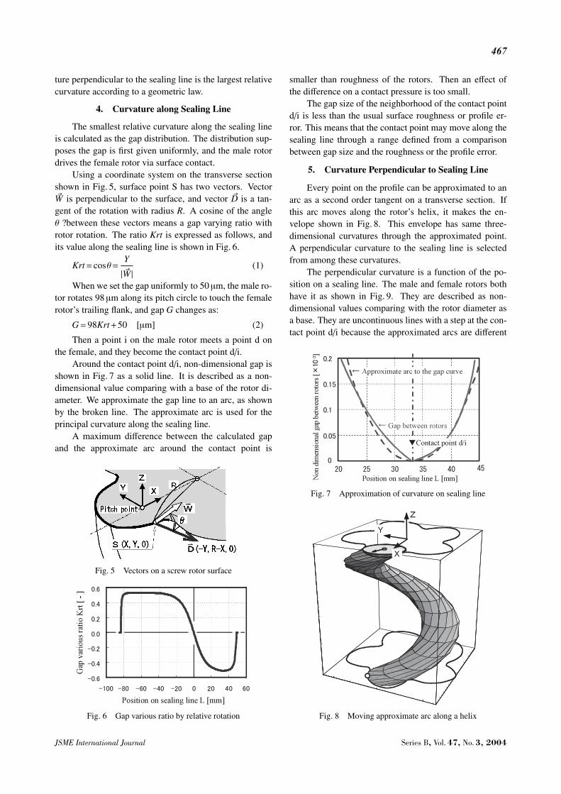
Using a coordinate system on the transverse sectionshown in Fig. 5, surface point S has two vectors. Vector�W is perpendicular to the surface, and vector �D is a tan-gent of the rotation with radius R. A cosine of the angleθ ?between these vectors means a gap varying ratio withrotor rotation. The ratio Krt is expressed as follows, andits value along the sealing line is shown in Fig. 6.
Krt= cosθ=Y
| �W | (1)
When we set the gap uniformly to 50 µm, the male ro-tor rotates 98 µm along its pitch circle to touch the femalerotor’s trailing flank, and gap G changes as:
G=98Krt+50 [µm] (2)
Then a point i on the male rotor meets a point d onthe female, and they become the contact point d/i.
Around the contact point d/i, non-dimensional gap isshown in Fig. 7 as a solid line. It is described as a non-dimensional value comparing with a base of the rotor di-ameter. We approximate the gap line to an arc, as shownby the broken line. The approximate arc is used for theprincipal curvature along the sealing line.
A maximum difference between the calculated gapand the approximate arc around the contact point is
Fig. 5 Vectors on a screw rotor surface
Fig. 6 Gap various ratio by relative rotation
smaller than roughness of the rotors. Then an effect ofthe difference on a contact pressure is too small.
The gap size of the neighborhood of the contact pointd/i is less than the usual surface roughness or profile er-ror. This means that the contact point may move along thesealing line through a range defined from a comparisonbetween gap size and the roughness or the profile error.
5. Curvature Perpendicular to Sealing Line
Every point on the profile can be approximated to anarc as a second order tangent on a transverse section. Ifthis arc moves along the rotor’s helix, it makes the en-velope shown in Fig. 8. This envelope has same three-dimensional curvatures through the approximated point.A perpendicular curvature to the sealing line is selectedfrom among these curvatures.
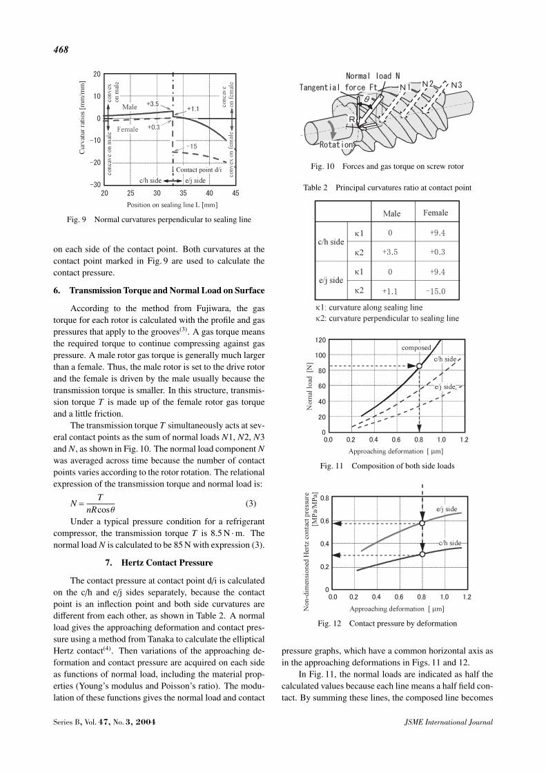
The perpendicular curvature is a function of the po-sition on a sealing line. The male and female rotors bothhave it as shown in Fig. 9. They are described as non-dimensional values comparing with the rotor diameter asa base. They are uncontinuous lines with a step at the con-tact point d/i because the approximated arcs are different
Fig. 7 Approximation of curvature on sealing line
Fig. 8 Moving approximate arc along a helix
JSME International Journal Series B, Vol. 47, No. 3, 2004
468
Fig. 9 Normal curvatures perpendicular to sealing line
on each side of the contact point. Both curvatures at thecontact point marked in Fig. 9 are used to calculate thecontact pressure.
6. Transmission Torque and Normal Load on Surface
According to the method from Fujiwara, the gastorque for each rotor is calculated with the profile and gaspressures that apply to the grooves(3). A gas torque meansthe required torque to continue compressing against gaspressure. A male rotor gas torque is generally much largerthan a female. Thus, the male rotor is set to the drive rotorand the female is driven by the male usually because thetransmission torque is smaller. In this structure, transmis-sion torque T is made up of the female rotor gas torqueand a little friction.
The transmission torque T simultaneously acts at sev-eral contact points as the sum of normal loads N1, N2, N3and N, as shown in Fig. 10. The normal load component Nwas averaged across time because the number of contactpoints varies according to the rotor rotation. The relationalexpression of the transmission torque and normal load is:
N =T
nRcosθ(3)
Under a typical pressure condition for a refrigerantcompressor, the transmission torque T is 8.5 N ·m. Thenormal load N is calculated to be 85 N with expression (3).
7. Hertz Contact Pressure
The contact pressure at contact point d/i is calculatedon the c/h and e/j sides separately, because the contactpoint is an inflection point and both side curvatures aredifferent from each other, as shown in Table 2. A normalload gives the approaching deformation and contact pres-sure using a method from Tanaka to calculate the ellipticalHertz contact(4). Then variations of the approaching de-formation and contact pressure are acquired on each sideas functions of normal load, including the material prop-erties (Young’s modulus and Poisson’s ratio). The modu-lation of these functions gives the normal load and contact
Fig. 10 Forces and gas torque on screw rotor
Table 2 Principal curvatures ratio at contact point
Fig. 11 Composition of both side loads
Fig. 12 Contact pressure by deformation
pressure graphs, which have a common horizontal axis asin the approaching deformations in Figs. 11 and 12.
In Fig. 11, the normal loads are indicated as half thecalculated values because each line means a half field con-tact. By summing these lines, the composed line becomes
Series B, Vol. 47, No. 3, 2004 JSME International Journal
469
an integrated relationship between the normal load and theapproaching deformation.
Using this composed line, the given normal load 85 Nindicates a deformation of 0.8µm. Then this deformationmeans a contact pressure of 0.30S [MPa] at the c/h sideand 0.57 at the e/j side, as in Fig. 12. The larger pressure0.57 is important as an evaluation of the strength. Thesecontact pressures are indicated as non-dimensional valuescomparing with the weakest material’s strength S whichis explained in the next section.
8. Comparison Contact Pressure and Strength of Ro-tor Material
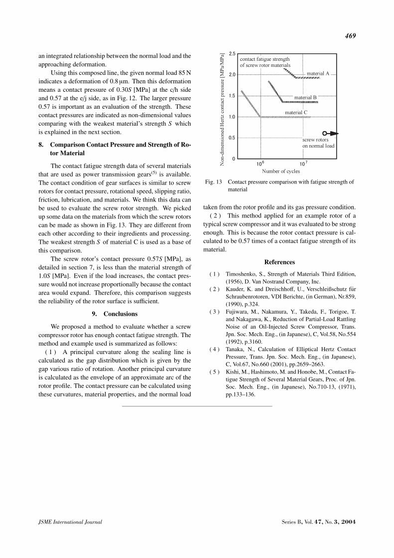
The contact fatigue strength data of several materialsthat are used as power transmission gears(5) is available.The contact condition of gear surfaces is similar to screwrotors for contact pressure, rotational speed, slipping ratio,friction, lubrication, and materials. We think this data canbe used to evaluate the screw rotor strength. We pickedup some data on the materials from which the screw rotorscan be made as shown in Fig. 13. They are different fromeach other according to their ingredients and processing.The weakest strength S of material C is used as a base ofthis comparison.
The screw rotor’s contact pressure 0.57S [MPa], asdetailed in section 7, is less than the material strength of1.0S [MPa]. Even if the load increases, the contact pres-sure would not increase proportionally because the contactarea would expand. Therefore, this comparison suggeststhe reliability of the rotor surface is sufficient.
9. Conclusions
We proposed a method to evaluate whether a screwcompressor rotor has enough contact fatigue strength. Themethod and example used is summarized as follows:
( 1 ) A principal curvature along the sealing line iscalculated as the gap distribution which is given by thegap various ratio of rotation. Another principal curvatureis calculated as the envelope of an approximate arc of therotor profile. The contact pressure can be calculated usingthese curvatures, material properties, and the normal load
Fig. 13 Contact pressure comparison with fatigue strength ofmaterial
taken from the rotor profile and its gas pressure condition.( 2 ) This method applied for an example rotor of a
typical screw compressor and it was evaluated to be strongenough. This is because the rotor contact pressure is cal-culated to be 0.57 times of a contact fatigue strength of itsmaterial.
References
( 1 ) Timoshenko, S., Strength of Materials Third Edition,(1956), D. Van Nostrand Company, Inc.
( 2 ) Kauder, K. and Dreischhoff, U., Verschleißschutz furSchraubenrotoren, VDI Berichte, (in German), Nr.859,(1990), p.324.
( 3 ) Fujiwara, M., Nakamura, Y., Takeda, F., Torigoe, T.and Nakagawa, K., Reduction of Partial-Load RattlingNoise of an Oil-Injected Screw Compressor, Trans.Jpn. Soc. Mech. Eng., (in Japanese), C, Vol.58, No.554(1992), p.3160.
( 4 ) Tanaka, N., Calculation of Elliptical Hertz ContactPressure, Trans. Jpn. Soc. Mech. Eng., (in Japanese),C, Vol.67, No.660 (2001), pp.2659–2663.
( 5 ) Kishi, M., Hashimoto, M. and Honobe, M., Contact Fa-tigue Strength of Several Material Gears, Proc. of Jpn.Soc. Mech. Eng., (in Japanese), No.710-13, (1971),pp.133–136.
JSME International Journal Series B, Vol. 47, No. 3, 2004