Embed Size (px)
Citation preview
The Influence of Rotor Deflection upon
Screw Compressor Performance
Ahmed Kovacevic, MSc, Dipl Ing
Prof Nikola Stosic, PhD, MSc, Dipl Ing, Prof Ian K. Smith, PhD, MSc, BEng
Centre for Positive Displacement Compressor Technology
City University, London EC1V 0HB, UK; Tel: +44 20 7040 8780; Fax: +44 20 7040 8566
e-mail: [email protected]
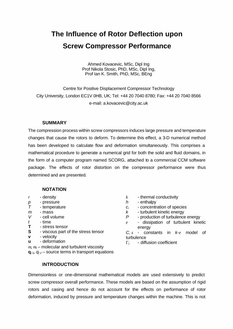
SUMMARY
The compression process within screw compressors induces large pressure and temperature
changes that cause the rotors to deform. To determine this effect, a 3-D numerical method
has been developed to calculate flow and deformation simultaneously. This comprises a
mathematical procedure to generate a numerical grid for both the solid and fluid domains, in
the form of a computer program named SCORG, attached to a commercial CCM software
package. The effects of rotor distortion on the compressor performance were thus
determined and are presented.
NOTATION
ρ - density p - pressure T - temperature m - mass V - cell volume t - time T - stress tensor S - viscous part of the stress tensor v - velocity u - deformation µ, µt – molecular and turbulent viscosity
κ - thermal conductivity h - enthalpy ci - concentration of species k - turbulent kinetic energy P - production of turbulence energy ε - dissipation of turbulent kinetic
energy C, σ - constants in k-ε model of turbulence Γφ - diffusion coefficient
qφS, qφV – source terms in transport equations
INTRODUCTION
Dimensionless or one-dimensional mathematical models are used extensively to predict
screw compressor overall performance. These models are based on the assumption of rigid
rotors and casing and hence do not account for the effects on performance of rotor
deformation, induced by pressure and temperature changes within the machine. This is not
significant when clearances are large. However, screw compressor rotors can now be
produced at an economic cost with tolerances as small as 5 micrometers while casing bores
can be manufactured on NC machine tools with a repeatability of 2 micrometers. Accordingly
it is possible to construct compressors with very small clearances and thereby minimise
internal leakage. They may then be made both smaller and more efficient. However, when
clearances are small, rotor deformation may affect compressor performance significantly and
even lead to seizure. Full 3-D calculation of compressor fluid flow and solid structure
interaction is then required to evaluate it.
Ferziger and Peric [2] showed that 3-D fluid flow in complex curvilinear geometries can be
analysed successfully by means of finite volume methods. Demirdzic and Muzaferija [1]
showed that by the use of moving frames on structured and unstructured grids, the same
numerical methods can be used for the simultaneous solution of fluid flow and structural
analysis.
The most extensive descriptions of contemporary grid generation methods are by Liseikin [7]
and Thompson et al [11]. By use of a grid generation procedure based on their methods
attached to an appropriate CCM solver, fluid and solid interactions within a system can be
predicted.
Apart from the authors' publications [3] - [6], there are hardly any other reported activities in
the use of 3D numerical methods for screw compressor studies. This is mainly because
existing grid generators and the majority of solvers are still unable to cope with the problems
associated with both the complexity of screw compressor geometry and the physics of the
compressor process.
The method used in this study employs a rack generation procedure to produce rotor profile
points and an analytical transfinite interpolation between them, with adaptive meshing on the
boundaries, to obtain a fully structured 3-D computational grid. The authors give this in detail
[4]. An interface program called SCORG (Screw COmpressor Rotor Geometry Grid
generator) was developed for this purpose. The grid is directly transferable to a CCM code
through its own pre-processor.
Apart from grid generation, some changes need to be made within the solver functions to
enable accurate and fast calculations. These include methods to maintain constant pressure
at the inlet and outlet ports and the interaction between the solid and fluid domains. An
interface program automatically generates user subroutines that contain these features and
prepares files to be attached to a general CCM solver.
GRID GENERATION
Grid generation of the screw compressor geometry is a necessary preliminary to CCM
calculation. Spatial domains that represent the metal material inside the rotors and the fluid
passages outside the rotors should both be defined by it. These are determined by the rotor
profile coordinates and their derivatives and are obtained by means of a rack generation
procedure described in detail by Stosic [9].
An algebraic grid generation method for screw compressor geometry has been derived,
based on a transfinite interpolation procedure described by Liseikin [7] and Thompson et al
[11]. This includes stretching functions to ensure grid orthogonality and smoothness, as
described by the authors [6]. The compressor spatial domain is divided into a number of sub-
domains, which allow the generation of a fully structured grid of discrete volumes within the
blocks. A composite grid is then made of several blocks patched together and based on a
single boundary fitted co-ordinate system. However, the grid for the fluid around the rotors
and the rotors themselves is generated simultaneously in a single block. This allows
distortion of the rotors to change the clearances by direct movement of the nodes within the
block while the boundary of the block remains unchanged.
MATHEMATICAL MODEL
The compressor flow and the structure of the compressor parts are fully described by the
mass averaged conservation equations of continuity, momentum, energy and space,
accompanied by the turbulence model equations and an equation of state for the working
fluid. These are given by Ferziger and Peric [2]. In the case of multiphase flow, a
concentration equation is added to the system. The numerical solution of such a system of
partial differential equations is then made possible by inclusion of constitutive relations in the
form of Stoke’s, Fick’s and Fourier’s law for the fluid momentum, concentration and energy
equations respectively and Hooke’s law for the momentum equations of a thermo-elastic
solid body.
All these equations are conveniently written in the form of the following generic transport
equation:
( ) grads S V
V S S S V
ddV d d ds q dV
dt φ φ φρφ ρφ φ+ − ⋅ = Γ ⋅ + ⋅ + ⋅∫ ∫ ∫ ∫ ∫v v s s q (1)
Here φ stands for the transported variable and Γφ is diffusion coefficient. The meaning of the
source terms, qφS and qφV for the fluid and solid transport equations is given in Table 1.
The resulting system of partial differential equations is discretised by means of the finite
volume method in a general Cartesian coordinate frame. This method enhances the
conservation of governing equations while at the same time enables a coupled system of
equations to be solved simultaneously for both the solid and fluid regions.
Table 1 Terms in the generic transport equation (1)
Equation φ Γφ qφS qφV
Fluid Momentum vi µef f ( )T 2
grad div3eff eff ipµ µ
− + ⋅ v v I i b,if
Solid Momentum
iu
t
∂∂
η ( ) ( )Tgrad div 3 iK Tη λ α + ∆ ⋅ u u - I i
b,if
Energy e t
T
k
e T
µσ
+∂ ∂
gradk e
pe T p
∂− ⋅∂ ∂ ∂
T: grad v + h
Concentration ci ,effiDρ 0 cis
Space 1ρ
0 0 0
Turbulent kinetic energy
K t
k
µµ
σ+ 0 P ρε−
Dissipation ε t
ε
µµ
σ+
1C Pk
ε −2
2 3 divC Ck
ερ ρε− v
This mathematical scheme is accompanied by boundary conditions for both the solid and
fluid parts. The authors [5] introduced special treatment of the compressor fluid boundaries.
The compressor was positioned between two relatively small suction and discharge
receivers. By this means, the compressor system is separated from the surroundings by
adiabatic walls only. It communicates with its surroundings through the mass and energy
sources or sinks placed in these receivers. This way of maintaining constant suction and
discharge pressures is given by the authors [6]. The solid part of the system is constrained
by both Dirichlet and Neuman boundary conditions through zero displacement in the
restraints and zero traction elsewhere. Connection between the solid and fluid parts is
determined explicitly through the energy equation if the temperature and displacement from
the solid body surface are boundary conditions for the fluid flow and vice versa.
A commercial CCM solver was used to obtain the distribution of pressure, temperature,
velocity and the density fields throughout the fluid domain as well as the deformation and
stresses of the solid compressor elements. Based on the solution of these equations, integral
parameters of screw compressor performance were calculated, as shown by Kovacevic et.
al. [6] and Stosic et. al. [10].
PRESENTATION AND DISCUSSION OF THE RESULTS
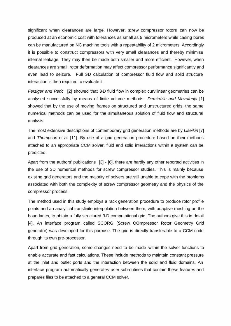
Interaction between the fluid flow and the solid parts is analysed in this paper for three
common applications of screw compressors, each with the same geometry, as shown in
Figure 1.
These are: an oil-injected air compressor of moderate pressure ratio, a dry air compressor, in
which the pressure ratio is low, and a high pressure oil flooded compressor. In all three
cases, the rotor profiles are of the ‘N’ type with a 5/6 lobe configuration, as presented by
Stosic et. al. [8]. The rotor outer diameters are 128 and 101 mm for the male and female
rotors respectively, and their centre distance is 90 mm. The rotor length to diameter ratio is
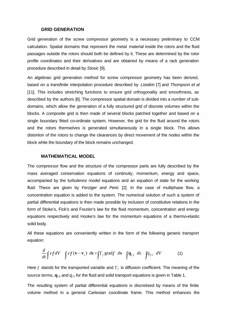
1.65. The numerical mesh for the test case in this study comprises 513,617 cells of which
162,283 describe the solid part of the rotors, 189,144 other cells map the fluid parts between
the rotors while the rest specify the suction and discharge ports and oil openings. A cross
section through the mesh for the rotors and their fluid paths is presented in Figure 2.
Figure 1 Cross section of rotors (left) and compressor (right)
Figure 2 Numerical mesh for rotors (left) and their fluid parts (right)
The grid and other control parameters generated by the interface were applied to COMET, a
commercial CCM solver of the StarCD group. The calculations were carried out on a
computer powered by an Athlon 800 MHz processor and 1 GB memory. Compressor rotation
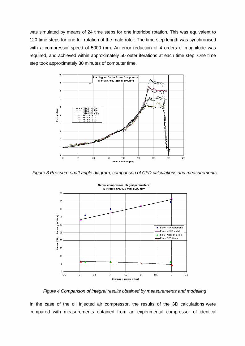
was simulated by means of 24 time steps for one interlobe rotation. This was equivalent to
120 time steps for one full rotation of the male rotor. The time step length was synchronised
with a compressor speed of 5000 rpm. An error reduction of 4 orders of magnitude was
required, and achieved within approximately 50 outer iterations at each time step. One time
step took approximately 30 minutes of computer time.
Figure 3 Pressure-shaft angle diagram; comparison of CFD calculations and measurements
Figure 4 Comparison of integral results obtained by measurements and modelling
In the case of the oil injected air compressor, the results of the 3-D calculations were
compared with measurements obtained from an experimental compressor of identical
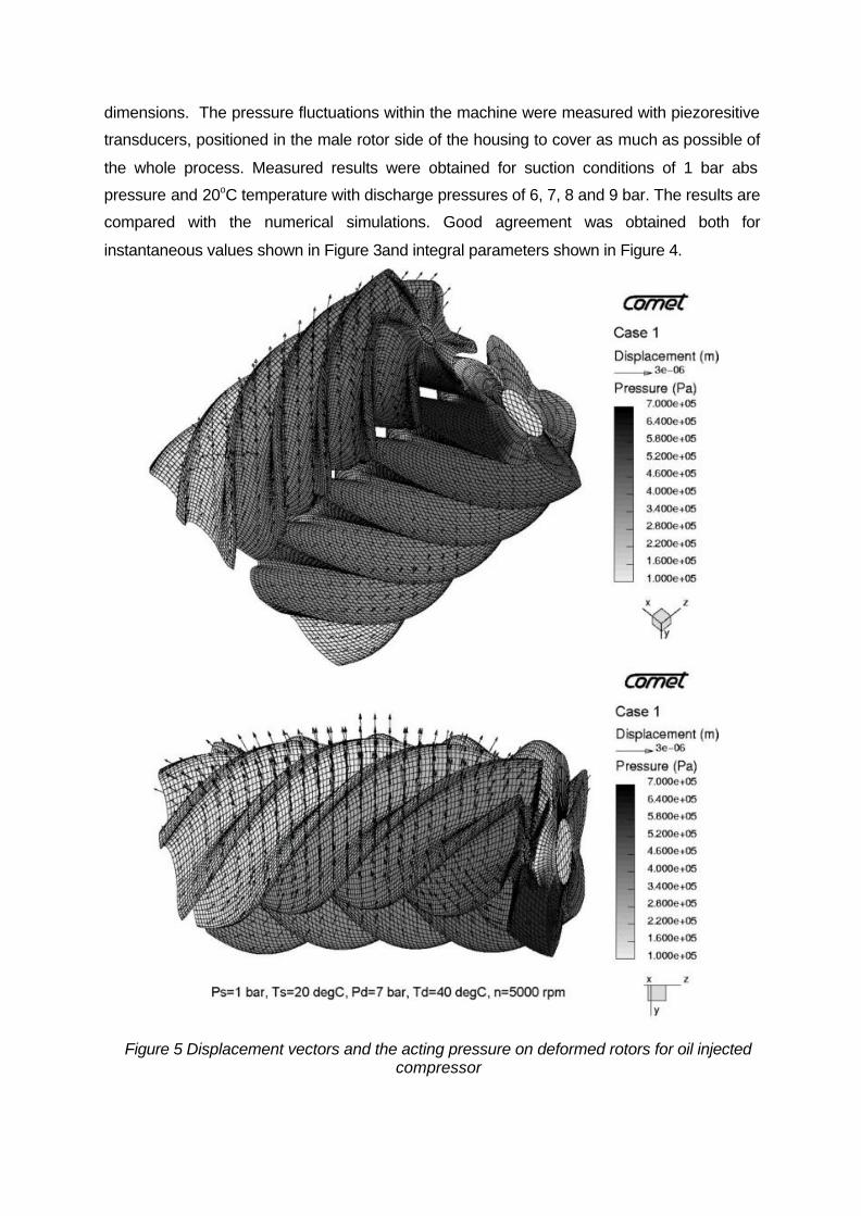
dimensions. The pressure fluctuations within the machine were measured with piezoresitive
transducers, positioned in the male rotor side of the housing to cover as much as possible of
the whole process. Measured results were obtained for suction conditions of 1 bar abs
pressure and 20oC temperature with discharge pressures of 6, 7, 8 and 9 bar. The results are
compared with the numerical simulations. Good agreement was obtained both for
instantaneous values shown in Figure 3and integral parameters shown in Figure 4.
Figure 5 Displacement vectors and the acting pressure on deformed rotors for oil injected compressor
The average exit temperature from the compressor was maintained at 40 oC at all pressures
by suitable injection of oil. Consequently, the rotor deformation was caused mainly by the
pressure rise in the working chamber. Two views of the rotors are presented in Figure 5, one
from the bottom of the rotors and the other one from the female rotor side. How the pressure
forces push the rotors apart and bend them has been made visible in the top diagram by
magnifying the distortion 20,000 times while maintaining the other dimensions at their original
scale. The leakage path through the sealing line between the rotors is biggest on the
discharge side where the pressure difference between the two rotors is the greatest. Also,
rotor bending increases the clearance gap between the rotor and the housing on the back
wall of the compressor. The female rotor is weaker than the male and therefore deforms
more. The maximum deformation in this case is only a few micrometers
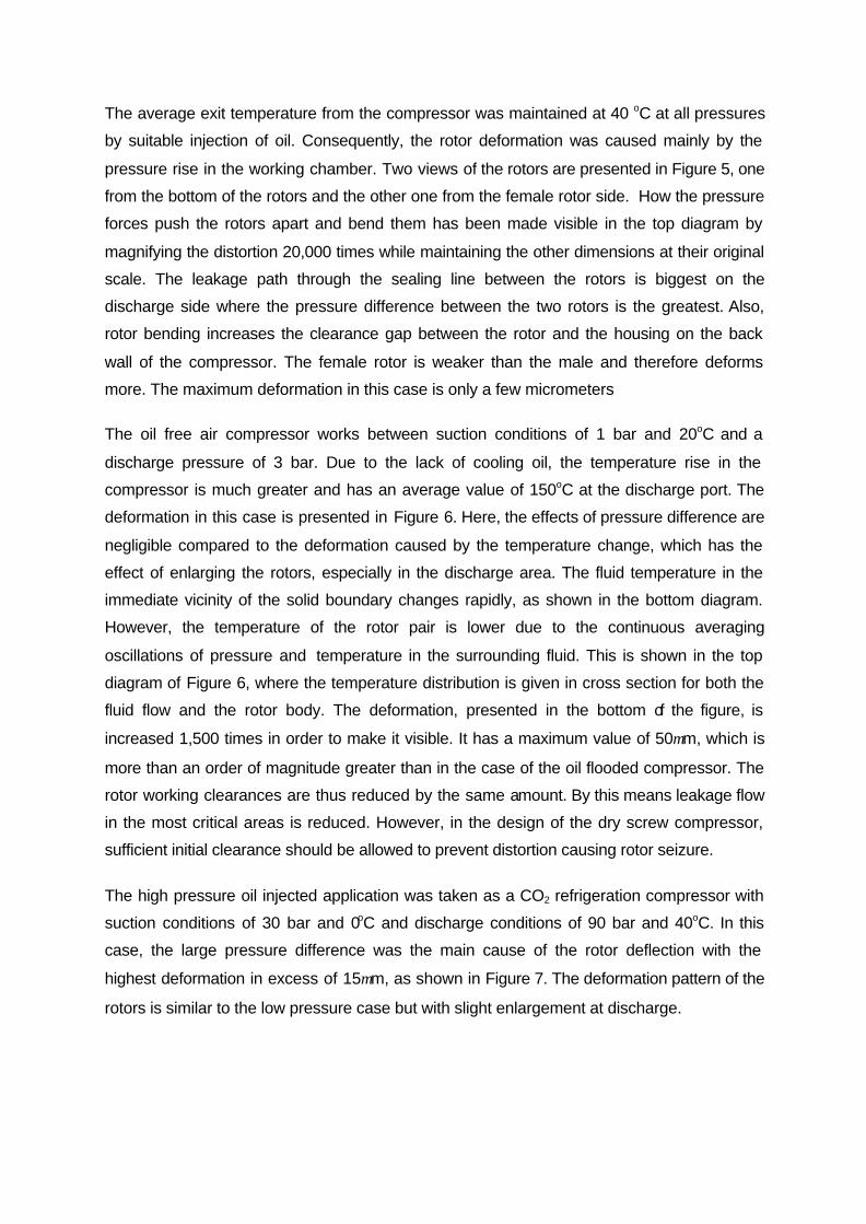
The oil free air compressor works between suction conditions of 1 bar and 20oC and a
discharge pressure of 3 bar. Due to the lack of cooling oil, the temperature rise in the
compressor is much greater and has an average value of 150oC at the discharge port. The
deformation in this case is presented in Figure 6. Here, the effects of pressure difference are
negligible compared to the deformation caused by the temperature change, which has the
effect of enlarging the rotors, especially in the discharge area. The fluid temperature in the
immediate vicinity of the solid boundary changes rapidly, as shown in the bottom diagram.
However, the temperature of the rotor pair is lower due to the continuous averaging
oscillations of pressure and temperature in the surrounding fluid. This is shown in the top
diagram of Figure 6, where the temperature distribution is given in cross section for both the
fluid flow and the rotor body. The deformation, presented in the bottom of the figure, is
increased 1,500 times in order to make it visible. It has a maximum value of 50µm, which is
more than an order of magnitude greater than in the case of the oil flooded compressor. The
rotor working clearances are thus reduced by the same amount. By this means leakage flow
in the most critical areas is reduced. However, in the design of the dry screw compressor,
sufficient initial clearance should be allowed to prevent distortion causing rotor seizure.
The high pressure oil injected application was taken as a CO2 refrigeration compressor with
suction conditions of 30 bar and 0oC and discharge conditions of 90 bar and 40oC. In this
case, the large pressure difference was the main cause of the rotor deflection with the
highest deformation in excess of 15µm, as shown in Figure 7. The deformation pattern of the
rotors is similar to the low pressure case but with slight enlargement at discharge.
Figure 6 Rotor displacement vectors and temperature distribution for an oil free compressor
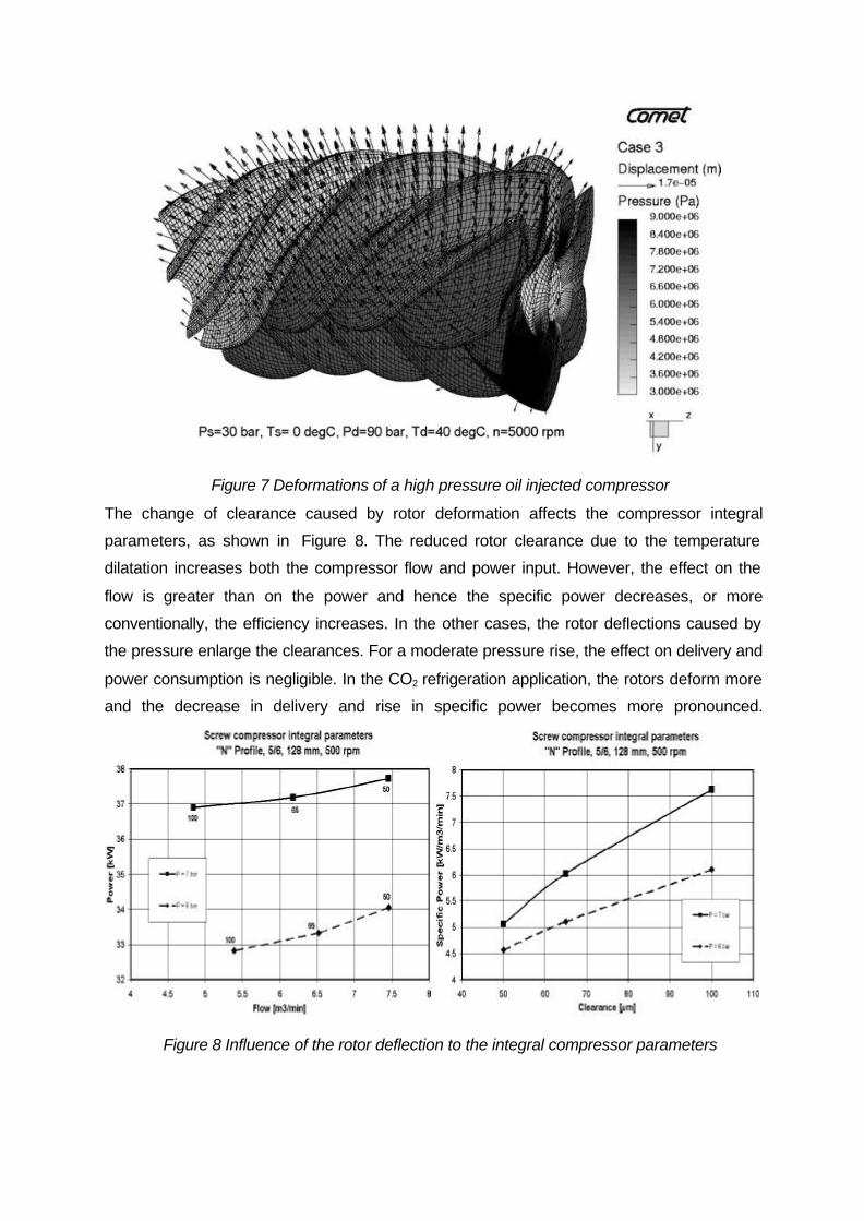
Figure 7 Deformations of a high pressure oil injected compressor
The change of clearance caused by rotor deformation affects the compressor integral
parameters, as shown in Figure 8. The reduced rotor clearance due to the temperature
dilatation increases both the compressor flow and power input. However, the effect on the
flow is greater than on the power and hence the specific power decreases, or more
conventionally, the efficiency increases. In the other cases, the rotor deflections caused by
the pressure enlarge the clearances. For a moderate pressure rise, the effect on delivery and
power consumption is negligible. In the CO2 refrigeration application, the rotors deform more
and the decrease in delivery and rise in specific power becomes more pronounced.
Figure 8 Influence of the rotor deflection to the integral compressor parameters
CONCLUSIONS
A full 3-D simulation has been carried out to determine how pressure and temperature
changes create internal distortion within screw compressors and thus affect their
performance. The effects of the change in working clearances are compared for different
compressor applications and presented through distortion diagrams and flow-power charts. A
high pressure rise has adverse effects but a high temperature rise may lead to an increase in
delivered flow and efficiency. As is shown in the results, the rotor deformation is dependent
on the compressor application. It must, therefore, be taken into account in every specific
compressor design.
REFERENCES 1. Demirdzic, I., Muzaferija S., “Numerical Method for Coupled Fluid Flow, Heat Transfer and Stress
Analysis Using Unstructured Moving Mesh with Cells of Arbitrary Topology”, Comp. Methods Appl. Mech Eng, 1995, Vol. 125, pp 235-255
2. Ferziger, J.H., Peric, M.; “Computational Methods for Fluid Dynamics”, Springer, Berlin, Germany, 1996
3. Kovacevic, A.; Stosic, N.; Smith, I.K.; “The CFD Analysis of a Screw Compressor Suction Flow“, 2000 International Compressor Conference at Purdue University, West Lafayette, Indiana, July 2000, pp 909-916
4. Kovacevic, A., Stosic, N.; Smith, I.K.; “Grid Aspects of Screw Compressor Flow Calculations“, Proceedings of the ASME International Mechanical Engineering Congress, Orlando, Florida, November 2000, pp 79-82
5. Kovacevic, A.; Stosic, N.; Smith, I.K.; “Analysis of Screw Compressor by Means of Three-Dimensional Numerical Modelling“, International Conference on Compressor and their System, IMechE Conference Transactions 2001-7, London, 2001, p.23-32
6. Kovacevic, A.; Stosic, N.; Smith, I.K.; “CFD Analysis of Screw Compressor Performance “, In: “Advances of CFD in Fluid Machinery Design” edited by Elder, R.L, Tourlidakis, A, Yates M.K, Professional Engineering Publishing of ImechE, London, 2002
7. Liseikin, V.D., “Grid generation Methods“, Springer-Verlag, 1999 8. Stosic, N.; Smith, I.K.; Kovacevic; A, Aldis C.A., “The Design of a twin-screw compressor based on
a new rotor profile”, Journal of Engineering Design, v.8, n.4 1997, pp 389-399 9. Stosic, N.; “On Gearing of Helical Screw Compressor Rotors”, Proc IMechE, Journal of Mechanical
Engineering Science, 1998, Vol.212, pp 587 10. Stosic, N, Hanjalic K., “Development and Optimization of Screw Machines with a Simulation Model,
Part I: Profile Generation, Part II: Thermodynamic Performance Simulation and Design”, ASME Proceedings, Journal of Fluids Engineering,1997, Vol 119, p 659, p664
11. Thompson, J.F; Soni, B.; Weatherrill, N.P.; “Handbook of Grid generation”, CRC Press 1999