Embed Size (px)
Citation preview
8/12/2019 Analysis of SRS Effects at Different Number of Channels and Power Levels and on the Performance of DWDM Sys…
http://slidepdf.com/reader/full/analysis-of-srs-effects-at-different-number-of-channels-and-power-levels-and 1/5
I JSRD - I nternational Journal for Scientifi c Research & Development| Vol. 1, I ssue 6, 2013 | ISSN (onli ne): 2321-0613
All rights reserved by www.ijsrd.com 1287
Abstract — Stimulated Raman Scattering (SRS) effect is one
of the Nonlinear effects in Dense Wavelength Division
Multiplexed (DWDM) Fiber Optic Communication System.
The effect of Stimulated Raman Scattering causes power to
be transferred from the lower wavelength channel to thehigher wavelength channel. This will reduce the Optical
Signal to Noise Ratio (OSNR) for the high frequency
channel or low wavelength channel. SRS effect is studied
for different input power and for different number of
wavelengths. SRS effect could be reduced by setting
optimum optical power in the fiber. Various channel
(4,8,11) DWDM system for various power levels ofindividual channels is stimulated in the sample mode of
OPTSIM software for getting the effects of SRS like Power
Tilt in the optical spectrum, after the fiber.
Keyword: Ooptical Fiber Communication, Power Tilt, Fiber
Nonlinearity, DWDM, SRS, and OSNR.
I. INTRODUCTION
Wavelength Division Multiplexing (WDM) involves the
transmission of a number of different peak wavelengthoptical signals in parallel on a single optical fiber. The
WDM standard developed by the International
Telecommunication Union (ITU) specifies channelspacing’s in terms of frequency. WDM is a method of
combining multiple services on a single fiber specified by
ITU-T G.692. Many different wavelengths can be sent along
a fiber simultaneously in the 1300-1600nm spectrum. This is
achieved through WDM. WDM is nothing but N
independent optically formatted information streams each
transmitted at a different wavelength are combined with
optical multiplexer and send over the same fiber. Thewavelength in WDM must be properly spaced to avoid inter
channel interference. Dense wavelength division
multiplexing (DWDM) is a technology that puts data from
different sources together on an optical fiber, with each
signal carried at the same time on its own separate lightwavelength. Using DWDM, up to 80 (and theoreticallymore) separate wavelengths or channels of data can be
multiplexed into a light stream transmitted on a single
optical fiber. DWDM has been proven to be one of the
most capable technologies for communication systems.
Although usually applied to optical networks (ONs),
Wavelength Division Multiplexing (WDM), in general, is
used to increase the capacity of existing networks by
transmitting many channels simultaneously on a single fiber
optic line.
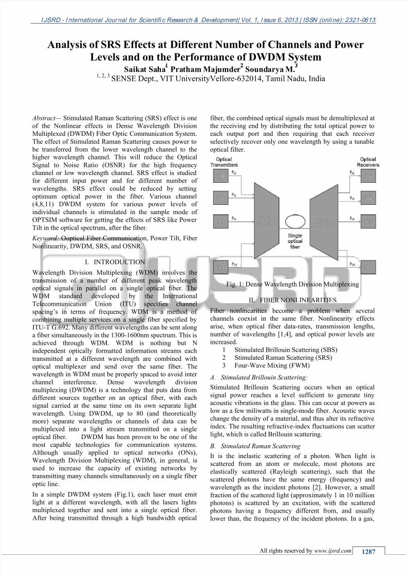
In a simple DWDM system (Fig.1), each laser must emit
light at a different wavelength, with all the lasers lights
multiplexed together and sent into a single optical fiber.
After being transmitted through a high bandwidth optical
fiber, the combined optical signals must be demultiplexed at
the receiving end by distributing the total optical power to
each output port and then requiring that each receiver
selectively recover only one wavelength by using a tunable
optical filter.
Fig. 1: Dense Wavelength Division Multiplexing
II. FIBER NONLINEARITIES
Fiber nonlinearities become a problem when severalchannels coexist in the same fiber. Nonlinearity effects
arise, when optical fiber data-rates, transmission lengths,
number of wavelengths [1,4], and optical power levels are
increased.
1 Stimulated Brillouin Scattering (SBS)
2 Stimulated Raman Scattering (SRS)
3 Four-Wave Mixing (FWM)
A. Stimulated Brillouin Scattering:
Stimulated Brillouin Scattering occurs when an optical
signal power reaches a level sufficient to generate tiny
acoustic vibrations in the glass. This can occur at powers aslow as a few miliwatts in single-mode fiber. Acoustic waves
change the density of a material, and thus alter its refractive
index. The resulting refractive-index fluctuations can scatter
light, which is called Brillouin scattering.
B. Stimulated Raman Scattering
It is the inelastic scattering of a photon. When light is
scattered from an atom or molecule, most photons are
elastically scattered (Rayleigh scattering), such that the
scattered photons have the same energy (frequency) and
wavelength as the incident photons [2]. However, a small
fraction of the scattered light (approximately 1 in 10 million
photons) is scattered by an excitation, with the scattered photons having a frequency different from, and usually
lower than, the frequency of the incident photons. In a gas,
Analysis of SRS Effects at Different Number of Channels and Power
Levels and on the Performance of DWDM SystemSaikat Saha Pratham Majumder Soundarya M.
1, 2, 3 SENSE Dept., VIT UniversityVellore-632014, Tamil Nadu, India
8/12/2019 Analysis of SRS Effects at Different Number of Channels and Power Levels and on the Performance of DWDM Sys…
http://slidepdf.com/reader/full/analysis-of-srs-effects-at-different-number-of-channels-and-power-levels-and 2/5
Analysis of SRS Effects at Different Number of Channels and Power Levels and on the Performance of DWDM System (IJSRD/Vol. 1/Issue 6/2013/004)
All rights reserved by www.ijsrd.com 1288
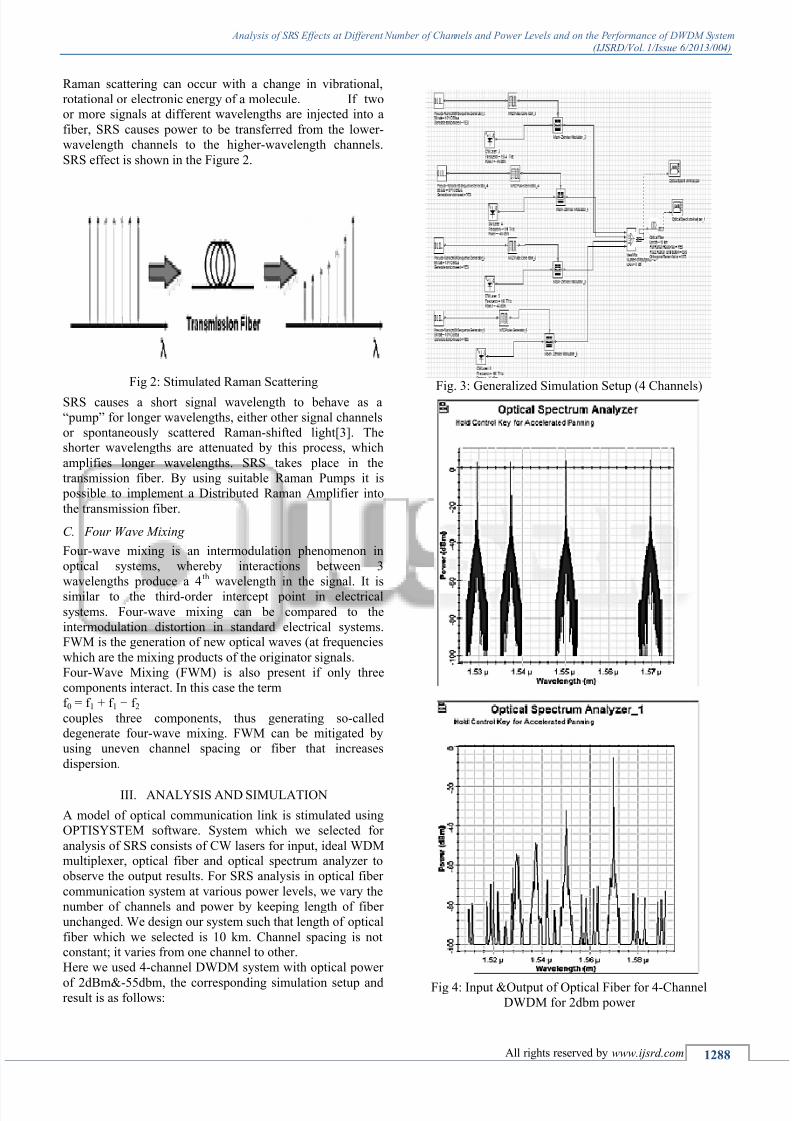
Raman scattering can occur with a change in vibrational,
rotational or electronic energy of a molecule. If twoor more signals at different wavelengths are injected into a
fiber, SRS causes power to be transferred from the lower-
wavelength channels to the higher-wavelength channels.
SRS effect is shown in the Figure 2.
Fig 2: Stimulated Raman Scattering
SRS causes a short signal wavelength to behave as a
“pump” for longer wavelengths, either other signal channels
or spontaneously scattered Raman-shifted light[3]. Theshorter wavelengths are attenuated by this process, which
amplifies longer wavelengths. SRS takes place in the
transmission fiber. By using suitable Raman Pumps it is
possible to implement a Distributed Raman Amplifier into
the transmission fiber.
C. Four Wave Mixing
Four-wave mixing is an intermodulation phenomenon in
optical systems, whereby interactions between 3
wavelengths produce a 4th
wavelength in the signal. It is
similar to the third-order intercept point in electrical
systems. Four-wave mixing can be compared to the
intermodulation distortion in standard electrical systems. FWM is the generation of new optical waves (at frequencies
which are the mixing products of the originator signals.
Four-Wave Mixing (FWM) is also present if only three
components interact. In this case the term
f 0 = f 1 + f 1 − f 2couples three components, thus generating so-calleddegenerate four-wave mixing. FWM can be mitigated by
using uneven channel spacing or fiber that increases
dispersion.
III. ANALYSIS AND SIMULATION
A model of optical communication link is stimulated using
OPTISYSTEM software. System which we selected for
analysis of SRS consists of CW lasers for input, ideal WDMmultiplexer, optical fiber and optical spectrum analyzer to
observe the output results. For SRS analysis in optical fiber
communication system at various power levels, we vary the
number of channels and power by keeping length of fiber
unchanged. We design our system such that length of optical
fiber which we selected is 10 km. Channel spacing is notconstant; it varies from one channel to other.
Here we used 4-channel DWDM system with optical power
of 2dBm&-55dbm, the corresponding simulation setup andresult is as follows:
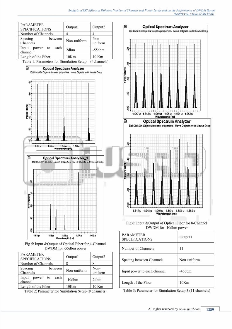
Fig. 3: Generalized Simulation Setup (4 Channels)
Fig 4: Input &Output of Optical Fiber for 4-Channel
DWDM for 2dbm power
8/12/2019 Analysis of SRS Effects at Different Number of Channels and Power Levels and on the Performance of DWDM Sys…
http://slidepdf.com/reader/full/analysis-of-srs-effects-at-different-number-of-channels-and-power-levels-and 3/5
Analysis of SRS Effects at Different Number of Channels and Power Levels and on the Performance of DWDM System (IJSRD/Vol. 1/Issue 6/2013/004)
All rights reserved by www.ijsrd.com 1289
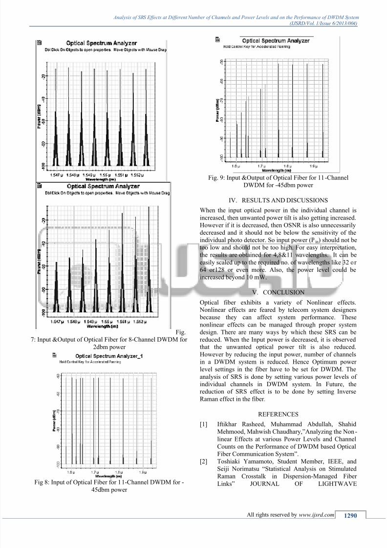
PARAMETER
SPECIFICATIONSOutput1 Output2
Number of Channels 4 4
Spacing between
Channels Non-uniform
Non-
uniform
Input power to eachchannel
2dbm -55dbm
Length of the Fiber 10Km 10 KmTable 1: Parameters for Simulation Setup (4channels)
Fig 5: Input &Output of Optical Fiber for 4-Channel
DWDM for -55dbm power
PARAMETER
SPECIFICATIONSOutput1 Output2
Number of Channels 8 8
Spacing between
Channels Non-uniform
Non-
uniform
Input power to each
channel-10dbm 2dbm
Length of the Fiber 10Km 10 KmTable 2: Parameter for Simulation Setup (8 channels)
Fig 6: Input &Output of Optical Fiber for 8-Channel
DWDM for -10dbm power
PARAMETERSPECIFICATIONS
Output1
Number of Channels 11
Spacing between Channels Non-uniform
Input power to each channel -45dbm
Length of the Fiber 10Km
Table 3: Parameter for Simulation Setup 3 (11 channels)
8/12/2019 Analysis of SRS Effects at Different Number of Channels and Power Levels and on the Performance of DWDM Sys…
http://slidepdf.com/reader/full/analysis-of-srs-effects-at-different-number-of-channels-and-power-levels-and 4/5
Analysis of SRS Effects at Different Number of Channels and Power Levels and on the Performance of DWDM System (IJSRD/Vol. 1/Issue 6/2013/004)
All rights reserved by www.ijsrd.com 1290
Fig.7: Input &Output of Optical Fiber for 8-Channel DWDM for
2dbm power
Fig 8: Input of Optical Fiber for 11-Channel DWDM for -45dbm power
Fig. 9: Input &Output of Optical Fiber for 11-Channel
DWDM for -45dbm power
IV. RESULTS AND DISCUSSIONS
When the input optical power in the individual channel is
increased, then unwanted power tilt is also getting increased.
However if it is decreased, then OSNR is also unnecessarily
decreased and it should not be below the sensitivity of the
individual photo detector. So input power (Pin) should not be
too low and should not be too high. For easy interpretation,
the results are obtained for 4,8&11 wavelengths. It can be
easily scaled up to the required no. of wavelengths like 32 or
64 or128 or even more. Also, the power level could be
increased beyond 10 mW.
V.
CONCLUSION
Optical fiber exhibits a variety of Nonlinear effects. Nonlinear effects are feared by telecom system designers
because they can affect system performance. These
nonlinear effects can be managed through proper system
design. There are many ways by which these SRS can be
reduced. When the Input power is decreased, it is observedthat the unwanted optical power tilt is also reduced.
However by reducing the input power, number of channels
in a DWDM system is reduced. Hence Optimum power
level settings in the fiber have to be set for DWDM. The
analysis of SRS is done by setting various power levels of
individual channels in DWDM system. In Future, thereduction of SRS effect is to be done by setting Inverse
Raman effect in the fiber.
REFERENCES
[1] Iftikhar Rasheed, Muhammad Abdullah, Shahid
Mehmood, Mahwish Chaudhary,”Analyzing the Non-
linear Effects at various Power Levels and Channel
Counts on the Performance of DWDM based Optical
Fiber Communication System”.
[2] Toshiaki Yamamoto, Student Member, IEEE, and
Seiji Norimatsu “Statistical Analysis on Stimulated
Raman Crosstalk in Dispersion-Managed Fiber
Links” JOURNAL OF LIGHTWAVE

8/12/2019 Analysis of SRS Effects at Different Number of Channels and Power Levels and on the Performance of DWDM Sys…
http://slidepdf.com/reader/full/analysis-of-srs-effects-at-different-number-of-channels-and-power-levels-and 5/5
Analysis of SRS Effects at Different Number of Channels and Power Levels and on the Performance of DWDM System (IJSRD/Vol. 1/Issue 6/2013/004)
All rights reserved by www.ijsrd.com 1291
TECHNOLOGY,VOL. 21, NO. 10, OCTOBER
2003.[3] T.Sabapathi., S.Sundaravadivelu and Prabha. G,
“Analysis and Reduction of Stimulated Raman
Scattering in DWDM Fiber Optic Communication
System”, Int. Conference in Cape Institute of
Technology, May 2010.
[4]
T.Sabapathi and S.Sundaravadivelu, “Analysis ofBottle neck in DWDM Fiber Optic Communication
System” Optik – International Journal for light and
Electron optics, Article in Press doi: 10.1016, 2010 (
Available online from 9th
Dec 2010).